WO2021199519A1 - 制御装置、プログラムおよび制御方法 - Google Patents
制御装置、プログラムおよび制御方法 Download PDFInfo
- Publication number
- WO2021199519A1 WO2021199519A1 PCT/JP2020/047256 JP2020047256W WO2021199519A1 WO 2021199519 A1 WO2021199519 A1 WO 2021199519A1 JP 2020047256 W JP2020047256 W JP 2020047256W WO 2021199519 A1 WO2021199519 A1 WO 2021199519A1
- Authority
- WO
- WIPO (PCT)
- Prior art keywords
- program
- control
- control device
- data
- execution
- Prior art date
- Legal status (The legal status is an assumption and is not a legal conclusion. Google has not performed a legal analysis and makes no representation as to the accuracy of the status listed.)
- Ceased
Links
Images




Classifications
-
- G—PHYSICS
- G05—CONTROLLING; REGULATING
- G05B—CONTROL OR REGULATING SYSTEMS IN GENERAL; FUNCTIONAL ELEMENTS OF SUCH SYSTEMS; MONITORING OR TESTING ARRANGEMENTS FOR SUCH SYSTEMS OR ELEMENTS
- G05B19/00—Program-control systems
- G05B19/02—Program-control systems electric
- G05B19/04—Program control other than numerical control, i.e. in sequence controllers or logic controllers
- G05B19/05—Programmable logic controllers, e.g. simulating logic interconnections of signals according to ladder diagrams or function charts
- G05B19/056—Programming the PLC
-
- G—PHYSICS
- G06—COMPUTING OR CALCULATING; COUNTING
- G06F—ELECTRIC DIGITAL DATA PROCESSING
- G06F9/00—Arrangements for program control, e.g. control units
- G06F9/06—Arrangements for program control, e.g. control units using stored programs, i.e. using an internal store of processing equipment to receive or retain programs
- G06F9/46—Multiprogramming arrangements
- G06F9/48—Program initiating; Program switching, e.g. by interrupt
- G06F9/4806—Task transfer initiation or dispatching
- G06F9/4843—Task transfer initiation or dispatching by program, e.g. task dispatcher, supervisor, operating system
- G06F9/4881—Scheduling strategies for dispatcher, e.g. round robin, multi-level priority queues
-
- G—PHYSICS
- G06—COMPUTING OR CALCULATING; COUNTING
- G06F—ELECTRIC DIGITAL DATA PROCESSING
- G06F9/00—Arrangements for program control, e.g. control units
- G06F9/06—Arrangements for program control, e.g. control units using stored programs, i.e. using an internal store of processing equipment to receive or retain programs
- G06F9/46—Multiprogramming arrangements
- G06F9/48—Program initiating; Program switching, e.g. by interrupt
- G06F9/4806—Task transfer initiation or dispatching
- G06F9/4812—Task transfer initiation or dispatching by interrupt, e.g. masked
-
- G—PHYSICS
- G05—CONTROLLING; REGULATING
- G05B—CONTROL OR REGULATING SYSTEMS IN GENERAL; FUNCTIONAL ELEMENTS OF SUCH SYSTEMS; MONITORING OR TESTING ARRANGEMENTS FOR SUCH SYSTEMS OR ELEMENTS
- G05B2219/00—Program-control systems
- G05B2219/10—Plc systems
- G05B2219/15—Plc structure of the system
- G05B2219/15079—Multitasking, real time multitasking
-
- G—PHYSICS
- G05—CONTROLLING; REGULATING
- G05B—CONTROL OR REGULATING SYSTEMS IN GENERAL; FUNCTIONAL ELEMENTS OF SUCH SYSTEMS; MONITORING OR TESTING ARRANGEMENTS FOR SUCH SYSTEMS OR ELEMENTS
- G05B2219/00—Program-control systems
- G05B2219/20—Pc systems
- G05B2219/25—Pc structure of the system
- G05B2219/25343—Real time multitasking
-
- Y—GENERAL TAGGING OF NEW TECHNOLOGICAL DEVELOPMENTS; GENERAL TAGGING OF CROSS-SECTIONAL TECHNOLOGIES SPANNING OVER SEVERAL SECTIONS OF THE IPC; TECHNICAL SUBJECTS COVERED BY FORMER USPC CROSS-REFERENCE ART COLLECTIONS [XRACs] AND DIGESTS
- Y02—TECHNOLOGIES OR APPLICATIONS FOR MITIGATION OR ADAPTATION AGAINST CLIMATE CHANGE
- Y02P—CLIMATE CHANGE MITIGATION TECHNOLOGIES IN THE PRODUCTION OR PROCESSING OF GOODS
- Y02P90/00—Enabling technologies with a potential contribution to greenhouse gas [GHG] emissions mitigation
- Y02P90/02—Total factory control, e.g. smart factories, flexible manufacturing systems [FMS] or integrated manufacturing systems [IMS]
Definitions
- This disclosure relates to a control device that executes a plurality of programs having different priorities.
- Patent Document 1 discloses a control device that sequentially executes a plurality of tasks according to the priority of each task.
- control device such as a PLC
- the execution priority of the program that controls the control target is set high.
- a program related to a system service different from the so-called control has a low execution priority and is executed in the free time of the control cycle.
- the control device that controls the control target includes a processor, a storage unit that stores a plurality of programs, and a scheduler that manages a program that causes the processor to execute according to a priority within a predetermined cycle.
- the plurality of programs in the storage unit are the programs having the highest execution priority executed by the processor in the cycle, and are executed by the first program for the real-time control processing of the controlled object and the first program. It is a low-priority program and is executed when the second program for related processing related to real-time control and the execution priority are lower than the second program and there is free time in the processor in the cycle.
- the scheduler starts executing the second program within a cycle, and then the processor if a predetermined type of instruction code is executed in the second program. Includes a switching unit that interrupts the execution of the second program and starts the execution of the third program.
- the switching unit of the scheduler starts the execution of the second program when the processor is made to execute the program according to the priority in the cycle, and then is predetermined in the second program.
- the processor interrupts the execution of the second program and starts the execution of the third program.
- the real-time control process includes a process of generating a command value to a controlled object based on an intermediate code generated by the related process, and a predetermined type of command code extends over a plurality of cycles when executed. Contains instruction codes that generate intermediate codes.
- the command value can be generated in the real-time control process based on the intermediate code over a plurality of cycles generated in advance.
- the predetermined type of instruction code includes a waiting instruction code and a waiting instruction code described by using a code for determining whether the waiting condition is satisfied.
- the processor interrupts the execution of the second program and starts the execution of the third program. Can be done.
- the second program includes a program written in an interpreted language.
- control device can determine whether or not a predetermined type of instruction code is executed by using the analysis result of the instruction code by the interpreter.
- the system service includes processing a time series database that stores records containing data related to the controlled object in a time series.
- control device suspends the execution of the second program and starts the execution of the third program, so that the processing time of the time-series database for storing the records containing the data related to the controlled object in the time series Can be secured within the cycle.
- control device further sequentially stores, for each cycle, a data generation unit that generates data for configuring records to be stored in the time-series database, and data generated by the data generation unit. It comprises a non-blocking queue formed on volatile main memory, and the system service includes processing to read data from the non-blocking queue and store it in a time series database.
- data generated at a relatively high speed within a cycle can be stored in a time series database having a relatively slow access speed via a non-blocking queue.
- the controller comprises a time series database.
- the control device can include a time series database internally.
- control device further includes a remaining amount monitoring unit that monitors the remaining amount of memory in the non-blocking queue, and the switching unit informs the processor that the remaining amount of memory is being executed based on the result of comparison between the remaining amount of memory and the threshold value.
- the execution of the second program is interrupted, and the execution of the third program is started.
- the controller suspends the execution of the second program being executed and starts the execution of the third program based on the result of the comparison between the remaining memory of the non-blocking queue and the threshold value. Can be made to.
- the first program includes an instruction code for related processing to be executed when the execution of the second program is interrupted.
- the control device when the execution of the second program is interrupted, the control device can execute the instruction code of the related processing during the execution of the first program.
- the program according to this disclosure is a program executed by a control device having a processor for controlling a controlled object, and is a scheduler program that manages a program that causes the processor to execute according to a priority within a predetermined cycle.
- a second program for related processing related to real-time control, and a third program of system services that is executed when there is free time in the processor, which has a lower execution priority than the second program.
- the scheduler program starts execution of the second program within the cycle, and when a predetermined type of instruction code is subsequently executed in the second program, the processor executes the second program. Includes a switch program that interrupts and starts execution of a third program.
- the switch program is executed, so that the time for executing the third program can be secured within the cycle.
- the switch program is executed, so that the time for executing the third program can be secured within the cycle.
- the control method is a control method for controlling a control device having a processor for controlling a controlled object, and the control device has the highest execution priority executed by the processor in a predetermined cycle.
- a step of managing a program to be executed according to a degree is provided, and the step of managing the second program starts execution in a cycle, and then a predetermined type of instruction code is executed in the second program. It includes a step of determining whether or not to execute, and, if based on the determination, a step of causing the processor to suspend the execution of the second program and start the execution of the third program.
- the processor while the processor is executing the program according to the priority, it is possible to secure the time for executing the third program within the cycle. As a result, it is possible to provide a mechanism that can secure a time during which the system service can be executed within a predetermined cycle.
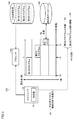
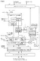
- FIG. 1 is a diagram schematically showing an application example.
- the control device 100 for controlling the control target provided in the FA production site includes a processor 102, a secondary storage device 108 such as an HDD (Hard Disc Drive), a scheduler 25, and a time series database. 180 and.
- the control device 100 includes a controller such as a PLC.
- the “controlled object” includes a machine or equipment, a sensor, or the like provided in the FA production line and subject to control. Machines or equipment include mechanical mechanisms such as robots, tables and conveyors.
- the scheduler 25 manages a program to be executed by the processor 102 according to the priority within a predetermined cycle.
- the time-series database 180 is configured to store records including data related to the control target generated for each cycle in the storage in a time-series manner.
- the predetermined cycle corresponds to the control cycle T.
- the secondary storage device 108 stores a plurality of programs so that the processor 102 can read them.
- the program stored in the secondary storage device 108 includes a first program, a second program, and a third program.
- the first program is the program having the highest execution priority executed by the processor 102 in the control cycle T, and is executed for the real-time control process of the controlled object.
- the second program is a program having a lower execution priority than the first program, and is executed for related processing related to real-time control.
- the third program is a system service program having a lower execution priority than the second program, and is executed when there is free time in the processor 102 in the control cycle T.
- the free time of the processor 102 indicates a period of idle state in which the processor 102 is not executing a program (process, task).
- the first program includes an "IEC program".
- the IEC program is a term that includes a program in which the entire program is scanned for each execution and one or more command values are calculated for each execution.
- An IEC program typically includes a program consisting of one or more instructions written in accordance with the International Standard IEC 61131-3 defined by the International Electrotechnical Commission (IEC).
- the IEC program may include instructions from a logic processing unit for sequence control and a motion processing unit for motion control.
- all the programs are executed (scanned) every control cycle T.
- IEC programs are suitable for controls that require immediacy and high speed, such as real-time control of objects.
- the IEC program is not limited to the instructions described in accordance with the international standard IEC61131-3, and may include instructions independently specified by the PLC manufacturer or vendor.
- the logic processing unit of sequence control basically executes a program (sequence program) described by one or more logic circuits that calculate input values, output values, internal values, etc. in order from the beginning to the end. Is. In one control cycle T, the program is executed from the beginning to the end, and in the next control cycle T, the program is executed again from the beginning to the end.
- the sequence program is a program that expresses an electric circuit.
- the motion processing unit of motion control follows the intermediate code output by the control application processing unit, which will be described later, with respect to the position, speed, acceleration, jerk, angle, angular speed, and angular acceleration of the servomotor and other actuators included in the control target. , Includes processing to calculate numerical values such as angular jerk as command values. Also in motion control, a program (motion processing program) described by a function block, a numerical calculation formula, or the like is executed from the beginning to the end in one control cycle T. That is, the command value is calculated (updated) for each control cycle T. Since the intermediate code used by the motion processing unit often includes an instruction capable of calculating a command value over a plurality of control cycles T, the timing at which the motion processing unit acquires the intermediate code does not have to be each control cycle T. good.
- the second program includes a control application program.
- the control application program is executed by the control application processing unit, for example, a device or machine that performs a specific processing or operation using CNC (Computer Numerical Control) and / or an industrial robot, and theirs. Processing related to control can be realized.
- CNC Computer Numerical Control
- the second program includes a program consisting of one or more instructions for realizing related processing related to real-time control of the controlled object, and is basically a control application program not included in the "IEC program". Including programs such as. As an example, the second program is described in the G language in CNC and in the robot language in industrial robot control. These languages include interpreted languages. The second program written in the interpreter language is executed by an interpreter method that sequentially interprets and executes the instruction code. The second program is not limited to the program written in the interpreter language, and may be written in the same IEC program language as the first program.
- the processor 102 provides an interpreter by executing an interpreter program.
- the interpreter interprets one or more instruction codes described in the second program, and based on the interpreted contents, generates an intermediate code for the motion processing unit to calculate the command value for each control cycle T. do. Since the intermediate code is generated for each one or a plurality of instruction codes described in the second program, a plurality of intermediate codes are often generated from one second program. The generation of such intermediate code can be included in the related processing described above.
- a function capable of calculating a command value can be specified by inputting the time (or time) of the control cycle T. That is, the intermediate code may be a function for the motion processing unit to calculate a command value for each control cycle T. By using such a function, the motion processing unit can calculate the command value in each control cycle T by sequentially referring to the intermediate code generated by the second program.
- the scheduler 25 causes the processor 102 to execute the first program, the second program, and the third program according to the priority of each program in the control cycle T.
- Each of the first to third programs is set with a priority indicating the degree to which the program should be executed with priority over other programs.
- the processor 102 starts executing the first program (time t0), and when the first program finishes executing, starts executing the second program (time). t1).
- the switching unit 26 included in the scheduler 25 switches the program to be executed by the processor 102 (step R2, time t2). In the switching, the switching unit 26 causes the processor 102 to suspend the execution of the second program and start the execution of the third program (steps R3 and R4).
- the free time of the processor 102 is provided in the control cycle T, and the third program is executed in this free time. As a result, it is possible to secure a time during which the system service can be executed within the control cycle T.
- the system service may include, for example, processing of the time series database 180. Therefore, the processing time of the time series database 180 can be secured within the control cycle T.
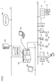
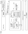
- FIG. 2 is a schematic diagram showing an overall configuration example of the control system 1 according to the embodiment.
- the control system 1 according to the embodiment includes a control device 100 that controls a controlled object as a main component.
- the control device 100 may be embodied as a kind of computer such as a PLC.
- the control device 100 is connected to the field device group 8 via the fieldbus 2 and is connected to one or more display devices 300 via the fieldbus 4.
- the control device 100 exchanges data with and from the connected device via each bus or network.
- fieldbus is also referred to as “fieldbus”, but for the sake of simplification of description, it is collectively referred to as “fieldbus” in the following description. That is, the "fieldbus” of the embodiment may include a "field network” in addition to the "fieldbus".
- the control device 100 performs a control calculation that executes various calculations for controlling the manufacturing device and the equipment.
- the control device 100 includes data measured by the field device group 8 and transferred to the control device 100 (hereinafter, also referred to as “input data”) and various types of data calculated by the control calculation process. Performs input / output processing to acquire data.
- the control device 100 further has a time series database 180.
- the time series database 180 stores various data acquired by the input / output process in a time series.
- the time series database 180 is shown as a time series DB 180.
- control device 100 performs a data generation process for generating a record including data related to a designated control target
- time series database 180 stores the data generated by the data generation process in a time series. ..
- time series data is a series of values obtained by continuously (or discontinuously) observing changes in data (observed values) for an arbitrary object over time. Means.
- the "observed value” is a concept that collectively refers to a value (actual value) that can be used in a control calculation in the control device 100, and is typically acquired from a controlled object and input to the control calculation. Values (measured values obtained from the field, etc.), output values for the control target determined by the control operation based on the acquired input values (command values given to the field, etc.), operations calculated in the process of the control operation It can include values (arbitrary variable values) and the like. That is, the "observed value” includes an arbitrary value that can be stored as data in the control device 100 or can be output externally as data from the control device 100.
- EtherCAT registered trademark
- EtherNet registered trademark
- DeviceNet registered trademark
- CompoNet registered trademark
- the field device group 8 includes a device that collects input data from a controlled object or a manufacturing device or a production line related to control (hereinafter, also collectively referred to as a “field”).
- a device for collecting such input data an input relay, various sensors (for example, an analog sensor, a temperature sensor, a vibration sensor, etc.) and the like are assumed.
- the field device group 8 further includes a device that gives some action to the field based on a command (hereinafter, also referred to as “output data”) generated by the control device 100.
- output data As a device that exerts some action on such a field, an output relay, a contactor, a servo driver and a servo motor, and any other actuator are assumed.
- the field device group 8 exchanges data including input data and output data with the control device 100 via the field bus 2.
- the field device group 8 includes a remote I / O (Input / Output) device 12, a relay group 14, an image sensor 18, a camera 20, a servo driver 22, and a servo motor 24. Includes an industrial robot 251 and a robot controller 23.
- the field device group 8 is not limited to these, and any device may be adopted as long as it is a device capable of collecting input data or a device capable of performing some action based on output data.
- the remote I / O device 12 is a communication coupler that communicates via the fieldbus 2 and an input / output unit for acquiring input data and outputting output data (hereinafter, also referred to as “I / O unit”). And include. Input data and output data are exchanged between the control device 100 and the field via such an I / O unit.
- FIG. 2 shows an example in which digital signals are exchanged as input data and output data via the relay group 14.
- the I / O unit may be directly connected to the fieldbus.
- FIG. 2 shows an example in which the I / O unit 16 is directly connected to the fieldbus 2.
- the image sensor 18 performs image measurement processing such as pattern matching on the image data captured by the camera 20, and outputs the processing result to the control device 100.
- the servo driver 22 drives the servo motor 24 according to output data (for example, position command, speed command, etc.) from the control device 100.
- the display device 300 connected to the control device 100 via the fieldbus 4 receives an operation from the user and outputs a command or the like corresponding to the user operation to the control device 100, and the control device 100 outputs a command or the like according to the user operation.
- the support device 200 may be connectable to the control device 100.
- the support device 200 is a device that supports the preparation necessary for the control device 100 to control the controlled object.
- the support device 200 includes a program development environment (program creation / editing tool, parser, compiler, etc.) executed by the control device 100, parameters (configuration) of the control device 100 and various devices connected to the control device 100. It provides a setting environment for setting the operation, a process of outputting the generated user program to the control device 100, a process of modifying / changing the user program executed on the control device 100 online, and the like.
- the control device 100 also has a gateway process for outputting the data acquired by the input / output process and / or the data stored in the time series database 180 to the external device.
- FIG. 2 shows, as typical examples, a manufacturing execution system (MES: Manufacturing Execution System) 400 and an IoT (Internet of Things) service 450, which are connected to the control device 100 via an upper network 6.
- the control device 100 can provide information from the manufacturing device or equipment to be controlled to these external systems and services.
- MES Manufacturing Execution System
- IoT Internet of Things
- the manufacturing execution system 400 acquires information from the manufacturing equipment and facilities to be controlled, monitors and manages the entire production, and can also handle order information, quality information, shipping information, and the like.
- a database for storing information may be arranged inside the manufacturing execution system 400 or in parallel with the manufacturing execution system 400.
- the control device 100 can acquire manufacturing data indicating a manufacturing state in the manufacturing device or equipment to be controlled from the manufacturing execution system 400.
- the IoT service 450 is assumed to be a kind of cloud service composed of one or more computers connected to the upper network 6 or connected to the Internet connected to the upper network 6.
- the system constituting the IoT service 450 performs communication processing and transmits arbitrary information transmitted from the control device 100 to one or more processors (for example, CPU (Central Processing Unit), MPU (Micro-Processing Unit), GPU ( Graphics Processing Unit), etc.) and a system that outputs a predetermined output.
- processors for example, CPU (Central Processing Unit), MPU (Micro-Processing Unit), GPU ( Graphics Processing Unit), etc.
- the IoT service 450 is envisioned as a system that acquires information from controlled manufacturing equipment and facilities and performs macro or micro analysis. For example, data mining that extracts some characteristic trends contained in information from controlled manufacturing equipment and facilities, and machine learning tools for performing machine learning based on information from controlled target equipment and machines are assumed. Will be done.
- the control device 100 may be communicably connected to another control device 100.
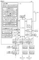
- FIG. 3 is a block diagram showing a hardware configuration example of the control device 100 according to the embodiment.
- the control device 100 includes an arithmetic processing unit and one or more I / O units 124-1, 124-2, ....
- the control device 100 includes a processor 102, a chipset 104, a main storage device 106, a secondary storage device 108 corresponding to internal storage, an upper network controller 110, a USB (Universal Serial Bus) controller 112, and an external storage. It includes an interface 114, a local bus controller 122, field bus controllers 118 and 120, a counter 126, and an RTC (Real Time Clock) 128.
- the processor 102 is composed of a CPU, an MPU, a GPU, etc., reads various programs stored in the secondary storage device 108, expands them in the main storage device 106, and executes the control according to the control target. , Realize various processes as described later.
- the secondary storage device 108 is composed of, for example, a non-volatile storage device such as an HDD (Hard Disk Drive) or an SSD (Solid State Drive).
- the main storage device 106 is composed of a volatile storage device such as a DRAM (Dynamic Random Access Memory) or a SRAM (Static Random Access Memory).
- the chipset 104 realizes the processing of the control device 100 as a whole by controlling the processor 102 and each device.
- the secondary storage device 108 in addition to the system program for realizing the basic operation, a user program created according to the manufacturing device or equipment to be controlled is stored.
- the upper network controller 110 exchanges data with the manufacturing execution system 400, the IoT service 450 (see FIG. 2), and the like via the upper network 6.
- the host network controller 110 is typically realized by using a dedicated circuit such as an ASIC (Application Specific Integrated Circuit) or an FPGA (Field-Programmable Gate Array).
- the USB controller 112 controls the exchange of data with the support device 200 via a USB (Universal Serial Bus) connection.
- the USB controller 112 is typically realized using a dedicated circuit such as an ASIC or FPGA.
- the external storage interface 114 is configured so that the external storage 116 can be attached and detached, data can be written to the external storage 116, and various data (user programs, trace data, etc.) can be read from the external storage 116.
- the external storage 116 corresponds to, for example, a volatile storage device including a flash memory such as an SD card.
- the counter 126 is used as a time reference for managing the execution timing of various processes in the control device 100.
- the counter 126 typically increments or decrements the counter value at predetermined intervals.
- the counter 126 may be implemented by using a high precision event timer (HPET: High Precision Event Timer) or the like, which is a hardware timer arranged on the system bus that drives the processor 102, or ASIC or FPGA. It may be mounted using a dedicated circuit such as.
- HPET High Precision Event Timer
- the RTC128 is a kind of counter that performs a timekeeping operation, and provides the current time to the processor 102 or the like.
- the local bus controller 122 is an interface for exchanging data with the I / O units 124-1, 124-2, ... Mounted on the control device 100.
- the local bus controller 122 is typically realized by using a dedicated circuit such as an ASIC or FPGA, but may be realized by software implementation.
- the local bus controller 122 is mainly composed of a processor, a main storage device, a storage, etc., and the processor reads out a system program (firmware) stored in the storage and puts it in the main storage device. By deploying and executing, the necessary processing is realized.
- the local bus controller 122 is a counter 123 used as a time reference for managing timing with the I / O units 124-1, 124-2, ..., Which are other devices connected via the local bus. have. Similarly, each of the I / O units 124-1, 124-2, ... Has a counter 125 used as a time reference for managing timing between the local bus controller 122 and other I / O units. doing. As the counter 123 and the counter 125, the same configuration as that of the counter 126 described above can be adopted.
- the fieldbus controller 118 controls the exchange of data with other devices via the fieldbus 2.
- the fieldbus controller 118 is typically realized by using a dedicated circuit such as an ASIC or FPGA, but may be realized by software implementation.
- the field bus controller 118 is mainly composed of a processor, a main storage device, a storage, etc., and the processor reads out a system program (firmware) stored in the storage and puts it in the main storage device. By deploying and executing, the necessary processing is realized.
- the fieldbus controller 118 has a counter 119 used as a time reference for managing timing with other devices.
- the fieldbus controller 120 exchanges data with other devices via the fieldbus 4.
- the fieldbus controller 120 is typically realized by using a dedicated circuit such as an ASIC or FPGA, but may be realized by software implementation.
- the field bus controller 120 is mainly composed of a processor, a main storage device, a storage, and the like, and the processor reads a system program (firmware) and the like stored in the storage to the main storage device. By deploying and executing, the necessary processing is realized.
- the fieldbus controller 120 has a counter 121 used as a time reference for managing timing with other devices.
- each device also has a counter used as a time reference for managing timing with the fieldbus controller 118 or the fieldbus controller 120.
- the same configuration as the counter 126 described above can be adopted.
- the fieldbus controllers 118 and 120 operate as a communication master for performing constant periodic communication via the fieldbus, and the counter value indicated by the counter of each device connected to the fieldbus and the counter indicated by the counters 119 and 121. The difference from the value is sequentially monitored, and if necessary, a synchronization signal for instructing the device in which the counter value is deviated to be corrected is output. In this way, the fieldbus controllers 118 and 120 perform the synchronization management process of giving a command to the device to match the counter value indicated by the counter of the device with the counter value indicated by the counters 119 and 121.
- the secondary storage device 108 stores a plurality of programs including the system program 149 and the user program.
- the system program 149 includes an OS (Operating System), an interpreter program 151 that realizes an interpreter, and the like.
- the user program includes a control program 152, a system service program 195 that realizes a system service, a variable management program 160, a scheduler program 170 that realizes a scheduler 25 when executed, an input program 172, and an output program 174.
- the scheduler program 170 includes a switch program 171 that realizes the switching unit 26 when executed.
- the control program 152 includes an IEC program 1541 which is an embodiment of the "first program”, a control application program 1542 which is an embodiment of the "second program”, a database writing program 156, and a remaining amount monitoring program 1544. And include.
- the database writing program 156 and the remaining amount monitoring program 1544 are executed, the processing related to the NBQ (Non-Blocking Queue) 158, which will be described later, is realized.
- the NBQ 158 is provided in the control device 100 in connection with database processing.
- the system service program 195 includes a database program 190, an upper connection program 192, and a gateway program 194, which are examples of the "third program".
- the database program 190 includes a database read program 191 that, when executed, reads data from the NBQ 158 for storage in the time series database 180.
- the time-series database 180 included in the control device 100 may be realized by utilizing the storage area provided by the secondary storage device 108 and / or the external storage 116.
- the secondary storage device 108 and the external storage 116 may be collectively referred to as “storage”.
- the volatile main storage device 106 may be referred to as "memory”.
- the time-series database 180 in the present embodiment includes, in addition to the storage area for storing the database file, processing by the processor 102 or the like for realizing various operations such as generation, writing, and reading of the database file, and various operations. It includes a buffering area or a working area for realizing the above.
- the storage area included in the time series database 180 can be provided in the main storage device 106 or the secondary storage device 108.
- FIG. 3 shows a configuration example in which the necessary processing is provided by the processor 102 executing the program, and a part or all of the provided processing is provided by a dedicated hardware circuit (for example, ASIC). Alternatively, it may be implemented using an FPGA or the like). Alternatively, the main part of the control device 100 may be realized by using hardware that follows a general-purpose architecture (for example, an industrial personal computer based on a general-purpose personal computer). In this case, virtualization technology may be used to execute a plurality of OSs having different uses in parallel, and to execute necessary applications on each OS.
- a general-purpose architecture for example, an industrial personal computer based on a general-purpose personal computer.
- virtualization technology may be used to execute a plurality of OSs having different uses in parallel, and to execute necessary applications on each OS.
- control device 100, the support device 200, and the display device 300 are configured as separate bodies, but all or part of these processes are performed by a single device. You may adopt the structure which is concentrated in.
- Control device software configuration example> Next, a software configuration example of the control device 100 according to the embodiment will be described.
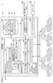
- FIG. 4 is a block diagram showing a software configuration example of the control device 100 according to the present embodiment.
- the control device 100 includes a PLC engine 150, a time series database 180, an upper connection program 192, and a gateway program 194.
- the PLC engine 150 is typically executed by the processor 102 of the control device 100 reading the system program stored in the secondary storage device 108 under the OS, deploying it in the main storage device 106, and executing the system program.
- An execution environment for various programs is provided, and various programs can be executed under the execution environment.
- the PLC engine 150 is configured to selectively execute the control program 152, the variable management program 160, the scheduler program 170, the input program 172, and the output program 174.
- NBQ158 is realized in the PLC engine 150.
- NBQ158 is realized by using, for example, a shared memory area prepared on a memory (volatile main storage device 106) that shares access from a plurality of tasks or processes.
- the NBQ 158 is realized by the buffer management process provided by the processor 102 executing the system program in addition to the shared memory area on the main storage device 106.
- the buffer management process defines a buffer pool consisting of a plurality of data areas (shared buffers described later) divided by a predetermined size in the shared memory area, and the state of each shared buffer (free, data is being stored, reserved). Etc.), including the process of managing such things.
- the system program for realizing the buffer management process includes a processor instruction such as a CAS (Compare And Swap) instruction for realizing a process such as writing data to an empty buffer.
- the buffer management process for realizing the NBQ 158 has an interface for accepting data writing from the control program 152 and an interface for accepting the dequeue from the database manager 182. With each of these interfaces, NBQ158 can be used in each of the logical data transfer paths from the database write program 156 to the time series database 180.
- variable management program 160, the scheduler program 170, the input program 172, and the output program 174 may be implemented as part of the system program. In this case, each process provided by these programs may be provided by a single system program.
- the control program 152 includes an IEC program 1541, a control application program 1542, a database writing program 156, and a remaining amount monitoring program 1544.
- the remaining amount monitoring program 1544 monitors the remaining amount of memory indicating the size of the free area of NBQ158, and outputs the monitoring result. Since the data stored in the NBQ 158 is read out and stored in the time series database 180, the storage area in which the read data is stored constitutes a free area until the data is subsequently written.
- the database write program 156 corresponds to a code that provides at least a part of the data generation process of the control device 100, and corresponds to, for example, every predetermined cycle (for example, every control cycle) by an instruction described in the IEC program 1541. Is called to generate data for constructing records to be stored in the time series database 180. More specifically, the NBQ 158 is arranged in the data transfer path from the database write program 156 to the time series database 180, and the database write program 156 writes the specified data directly to the time series database 180. Write to NBQ158 instead of writing.
- NBQ158 is a kind of buffer for continuing the processing of the database writing program 156 without waiting for the completion of data writing to the time series database 180.
- the data from the database writing program 156 is stored in the NBQ 158 in the form of a queue.
- the NBQ 158 sequentially stores the data generated by the database writing program 156.
- the data (queue) stored in the NBQ 158 is sequentially read out and stored in the time series database 180.
- the serialization communication program may be combined with the database writing program 156.
- the serialization communication program performs serialization processing on the data written from the database writing program 156 to the time series database 180. More specifically, the serialization communication program is executed by the PLC engine 150 and executes a process (serialization) of converting time series data into a storeable byte string. The target data is converted into a predetermined byte string by serialization processing before being stored in the time series database 180.
- the time-series database 180 includes a database manager 182 and a write buffer 184, in addition to a database file 186 in which data from the database write program 156 is stored in time series.
- the database manager 182 is typically realized by the processor 102 of the control device 100 executing the database program 190.
- the database manager 182 is in charge of adding records to the database file 186 and searching and extracting the records constituting the database file 186 in response to an external request.
- the read processing unit 183 (see FIG. 5) is realized.
- the read processing unit 183 sequentially reads the data stored in the NBQ 158 and adds it to the database file 186.
- the write buffer 184 is realized by using, for example, a storage area prepared on the main storage device 106 or a storage area prepared on the cache memory built in the storage.
- the database writing program 156 generates time-series data records from the data read from the NBQ 158 by the read processing unit 183, and sequentially stores the generated time-series data records in the database file 186.
- the database file 186 stores at least a part of the input data, the output data, the calculation data calculated in the control calculation by the control program 152, the manufacturing data, and the event data in a time series.
- the variable management program 160 manages values such as input data and output data that can be used by the PLC engine 150 in the form of variables. More specifically, the variable management program 160 includes a system variable 162 indicating the state of the control device 100 and a device variable indicating a value held by various devices connected to the control device 100 via the local bus or the field bus. It manages 164 and a user variable 166 indicating a value held by the IEC program 1541 executed by the control device 100.
- the scheduler program 170 having the switch program 171 manages resource allocation, execution timing, and the like for processes and tasks corresponding to execution units of the program executed by the control device 100.
- the input program 172 performs a process of acquiring input data from various devices connected to the control device 100 via a local bus or a field bus.
- the output program 174 outputs a command value (output data) calculated by the IEC program 1541 executed by the control device 100 and the control application program 1542 to the target device connected via the local bus or the field bus.
- a statistical record executed by the PLC engine 150 which statistically processes input data, output data, arithmetic data, manufacturing data, event data, etc. managed by the control device 100 and then writes to the time series database 180. Further programs may be provided.
- a method such as fragment aggregation approximation (PAA: Picewise Aggregate Approximation) or symbolization into discrete strings (SAX: Symbolic Aggregate approximation) can be used. PAA can find patterns in time series data, and the found patterns facilitate compression. Alternatively, SAX can facilitate compression and pattern discovery by converting time series data into character strings.
- the host connection program 192 of the control device 100 acquires manufacturing data from the manufacturing execution system 400.
- the variable management program 160 manages these acquired input data and manufacturing data as variables.
- the IEC program 1541 executes a predetermined control operation while referring to the system variable 162, the device variable 164, and the user variable 166 managed by the variable management program 160, and outputs the execution result (output data) to the variable management program. Output to 160.
- the database writing program 156 writes the specified observation value among the variables managed by the variable management program 160 into the NBQ 158.
- the database manager 182 of the time-series database 180 sequentially reads the data stored in the NBQ 158 in the form of a queue, and sequentially adds the records composed of the read data to the database file 186.
- the upper connection program 192 sets the values of the specified variables among the variables managed by the variable management program 160 and / or the specified records among the records constituting the database file 186 of the time series database 180 in a time series. It is output as data to the manufacturing execution system 400.
- a database connection program may be provided. Such a database connection program may, for example, send a query such as SQL to a relational database and execute a process of receiving a response.
- the gateway program 194 performs time-series data on the values of the specified variables among the variables managed by the variable management program 160 and / or the specified records among the records constituting the database file 186 of the time-series database 180. Is output to the IoT service 450.
- the IoT service 450 performs behavior analysis based on time-series data from the control device 100, and performs predictive maintenance of equipment and devices to be controlled.
- FIG. 5 is a schematic diagram showing an example of the functional configuration of the control device 100 according to the embodiment.
- the control device 100 includes a control application processing unit 30, a program processing unit 40, an I / O processing unit 50, a scheduler 25, a switching unit 26, a field network interface 55, and an upper network. It includes an interface 51 and a system service processing unit 185.
- the control device 100 of FIG. 5 further includes an NBQ 158 and a time series database 180 in association with these components.
- the scheduler 25 executes the control application processing unit 30, the program processing unit 40, the I / O processing unit 50, and the system service processing unit 185 in an order based on the execution priority of the program corresponding to each of these units. .. The order of implementation based on priority will be described later.
- the control application processing unit 30 executes the control application program 1542 in a cycle synchronized with the control cycle T according to the scheduling of the scheduler 25.
- the control application program 1542 is executed every two control cycles T, i.e. 2T.
- the execution cycle of the control application program 1542 is not limited to 2T.
- the control application processing unit 30 includes a program analysis unit 34 and a buffer 32 for storing the intermediate code 33.
- the program analysis unit 34 analyzes the instruction code described in the control application program 1542 by using the interpreter 31.
- the control application program 1542 generates the intermediate code 33 by being executed and stores it in the buffer 32.
- a part of the memory of the control device 100 constitutes a buffer 32.
- the program analysis unit 34 detects that a predetermined type of instruction code has been executed during the execution of the control application program 1542, the program analysis unit 34 stores the detection result as a flag F in the shared memory 159.
- a part of the memory of the control device 100 constitutes the shared memory 159.
- the interpreter 31 of the control application processing unit 30 interprets at least a part of the control application program 1542 and generates the intermediate code 33. That is, the interpreter 31 sequentially interprets and executes the control application program 1542 to generate the intermediate code 33, and stores the generated intermediate code 33 in the buffer 32.
- the program processing unit 40 executes the IEC program 1541 every control cycle T according to the scheduling of the scheduler 25.
- the program processing unit 40 executes (scans) the IEC program 1541 every predetermined control cycle T to calculate one or a plurality of command values. That is, the program processing unit 40 calculates the command value for each control cycle T according to the IEC program 1541.
- the program processing unit 40 includes a logic processing unit 41 that processes logic instructions such as a sequence program included in the IEC program 1541, a motion processing unit 42 that processes motion instructions included in the IEC program 1541, and a database writing unit 43. , The remaining amount monitoring unit 44 and the like.
- the motion processing unit 42 provides a function of calculating a command value for each control cycle T according to a motion command included in the IEC program 1541. Specifically, the motion processing unit 42 calculates a command value for each control cycle T according to an intermediate code 33 generated in advance by the interpreter 31. That is, the motion processing unit 42 provides a function of calculating a command value for each control cycle T according to the intermediate code 33 stored in advance in the buffer 32. Generally, since the instructions (codes) described in the control application program 1542 are executed sequentially, the calculation cycle of the command value cannot be guaranteed, but by using the intermediate code 33, the motion processing unit 42 controls. The command value can be calculated for each cycle T.
- the coordinate system corresponding to each control application may be used for the instruction described in the intermediate code 33.
- the interpreter 31 sequentially queues the generated intermediate code 33 into the buffer 32, and the motion processing unit 42 reads the intermediate code 33 in the order in which it is queued in the buffer 32.
- the "intermediate code” is a concept including an instruction for calculating a command value for each control cycle T.
- the “intermediate code” includes one or more instructions, or one or more functions.
- the intermediate code 33 may be any code as long as the motion processing unit 42 can calculate the command value for each control cycle T.
- the database writing unit 43 executes the database writing program 156 that is called during the execution of the IEC program 1541.
- the remaining amount monitoring unit 44 executes the remaining amount monitoring program 1544 called during the execution of the IEC program 1541.
- the database writing unit 43 that executes the database writing program 156 for each control cycle T is a “data generation unit” that generates data for configuring records to be stored in the time series database 180 for each control cycle T. Corresponds to. Specifically, the database writing unit 43 stores the generated data in the free area of the NBQ 158.
- the remaining amount monitoring unit 44 monitors the remaining amount of memory corresponding to the size of the free area of NBQ158, compares the remaining amount of memory with the threshold value, and sets the value indicating the comparison result as the variable MR of the shared memory 159. Set.
- the system service processing unit 185 executes the database program 190 in the free time of the processor 102 in the control cycle T according to the scheduling of the scheduler 25.
- the system service processing unit 185 includes a database manager 182 having a reading processing unit 183.
- the read processing unit 183 is realized by calling and executing the database read program 191 during the execution of the database program 190.
- the read processing unit 183 realizes a process of reading data from the NBQ 158 and storing it in the time series database 180.
- the upper network interface 51 mediates the exchange of data between the program processing unit 40 and the control application processing unit 30 and the device connected via the upper network 6.
- the field network interface 55 is an interface between the I / O processing unit 50 and the field.
- the I / O processing unit 50 executes the variable management program 160.
- the I / O processing unit 50 executes an I / O refresh process for updating the input data and the output data prior to the execution of the IEC program 1541 by the program processing unit 40.
- the values input from the fields via the field network interface 55 are set in the system variable 162, the device variable 164, and the user variable 166.
- the logic processing unit 41 and the motion processing unit 42 perform an operation using the input data set in the system variable 162, the device variable 164, and the user variable 166.
- command values (basically, logical values) calculated by the logic processing unit 41 and the motion processing unit 42 are calculated in the immediately preceding control cycle T.
- One or more command values (basically numerical values) are set in the system variable 162, the device variable 164 and the user variable 166, and the set command values are output to the field via the field network interface 55. NS.
- the NBQ 158 is prepared on the memory (volatile main storage device 106), for example, the memory capacity (size) of the NBQ 158 is limited. Therefore, if the system service processing unit 185 is not granted the right to use the resource including the processor 102 because there is no free time of the processor 102, that is, if the system service processing unit 185 cannot execute the database program 190, the NBQ 158 is free. The area, that is, the remaining memory is insufficient.
- control device 100 is configured so that the system service processing unit 185 secures the free time of the processor 102 capable of executing the database program 190. This makes it possible to deal with memory exhaustion.
- the switching unit 26 of the scheduler 25 detects that a predetermined type of instruction code has been executed by the control application program 1542 based on the value of the flag F, the control application is transmitted to the processor 102.
- the execution of the program 1542 is interrupted to secure the free time of the processor 102, and the processor 102 is started to execute the database program 190 (more specifically, the database read program 191) in the reserved free time.
- the processor 102 interrupts the execution of the control application program 1542 to secure the free time of the processor 102. , The processor 102 is made to start executing the database program 190 (more specifically, the database read program 191) in the reserved free time.
- the switching unit 26 transfers the program executed by the processor 102 from the control application program 1542 to the database program 190 based on the value of the flag F or the variable MR while the control application program 1542 is being executed in the control cycle T. Configured to switch. As a result, in the control cycle T, the free time for executing the database read program 191 can be secured, and the memory exhaustion of the NBQ 158 can be avoided.
- FIG. 6 is a schematic diagram showing a main part of processing related to the time series database 180 in the control device 100 according to the present embodiment.
- the control device 100 exchanges input data and output data with and from the field device group 8 via a local bus, a field bus, or the like.
- control program 152 including various operations for controlling the manufacturing device and the equipment is cyclically executed in the control cycle T.
- the control program 152 includes an instruction for starting the database writing program 156 when the data writing condition is satisfied.
- the database writing program 156 issues an instruction for writing the specified data (one or more variable values) to the time series database 180. For example, in FIG. 5, a "put" instruction is shown.
- the data collection processing process 153 which is a process for collecting and processing the data written from the database writing program 156 to the time series database 180, is performed in the control program 152 or in parallel with the control program 152. You may want to do it.
- Time series database 180 Data from the database writing program 156 is stored in the time series database 180 in time series (time series data).
- the time-series data stored in the time-series database 180 may be transmitted to a higher-level system and used for analysis processing or the like.
- necessary time-series data is extracted from the time-series database 180 by using the connection process 402 arranged in the higher-level system such as the manufacturing execution system 400 or the IoT service 450. Then, in the host system, analysis processing 404 such as time series analysis and data mining is performed on the extracted time series data.
- the time-series data stored in the time-series database 180 may be used in the abnormality detection process 198.
- the abnormality detection process 198 is realized by executing a program required by the PLC engine 150.
- the abnormality detection process 198 compares the time-series data from the time-series database 180 with the teacher data acquired in advance, and is a sign that some abnormality has occurred in the controlled object or that the abnormality has occurred. Make a judgment that is seen.
- cyclic execution is performed in the control program 152 control cycle T (for example, several hundred microseconds to several milliseconds).
- Data may be written to the time series database 180 in synchronization with the cyclic execution of the control program 152.
- the time series database 180 is basically configured by using the storage (secondary storage device 108 or external storage 116 (see FIG. 3)).
- Such storage generally has a large storage capacity, but has a low access speed (particularly, a write speed) and a large fluctuation in the access speed (for example, 100 milliseconds) as compared with the main storage device. ⁇ 1000 milliseconds).
- control device 100 provides a configuration capable of realizing data writing synchronized with the control cycle T even for the time series database 180 using the storage whose access speed is not high.
- a lock-free queue NBQ158 (see FIG. 4) is arranged.
- the execution of the database write program 156 is the data write. You can avoid the situation where you are interrupted by waiting. That is, it is possible to realize data writing to the time series database 180 synchronized with the control cycle T.
- the input data for example, the measured value of the analog sensor
- the output data for example, the position command and the speed
- arithmetic data for example, filter parameters and feature quantities used for abnormality detection processing
- manufacturing data for example, manufacturing status, product number, etc.
- the control device 100 includes an observation value related to the controlled object, a time associated with the observation value indicated by the time management process, and / or a counter value associated with the observation value indicated by the internal counter. , You may generate a record.
- the observed value is a value available to the processor 102.
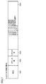
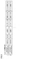
- FIG. 7 and 8 are diagrams showing an example of the data structure of the record stored in the time series database 180 in the control device 100 according to the embodiment.
- the record includes a time field 1821, a counter value field 1822, an index field 1823, and an observed value field 1824.
- the time field 1821 and the counter value field 1822 store information indicating the timing at which the corresponding data (one or more observed values) is acquired.
- the time field 1821 stores a time indicating the timing when the corresponding data is acquired (for example, a time managed by RTC128).
- the counter value field 1822 of the counter value from the counter managed by the control device 100 when the corresponding data is acquired, or the counter value from the counter for managing the timing in the field bus / local bus. At least one is stored.
- the index field 1823 stores a value (index value) that is incremented / decremented by a predetermined value according to the operation of writing a record to the database. Typically, a value is used that counts up by 1 each time a record is stored. For example, when an instruction to start the database writing program 156 is described in the IEC program 1541, the index value may be incremented according to the execution of the instruction to be started.
- the specified data (one or more observed values) is stored in the observed value field 1824.
- the data stored in the observed value field 1824 includes input data, output data, arithmetic data, manufacturing data, event data, and the like.
- the input data includes digital signals (state values) and analog signals (various measurement signals) acquired from various sensors.
- information for identifying the sensor that outputs the observed value may be stored together.
- a command value or the like output to the motion drive, the opening degree controller, or the like may be stored.
- information for specifying the actuator to which the command value is output may be stored together.
- variable values, transient values, etc. calculated by executing the IEC program 1541 may be stored.
- the information for identifying the IEC program 1541 or the task that output the calculation data may be stored together.
- an execution command value group (for example, a work part number, a lot number, a recipe number, etc.) received from the manufacturing execution system 400 may be stored.
- the execution command value group may include information that specifies an identification number that uniquely identifies the work, a type of work, and the like.
- event data information when the observed value exceeds or falls below a predetermined threshold value, information when a predetermined abnormality flag or the like is turned on, may be stored. Information such as variables that generated event data may be included.
- the event data may be generated when predetermined conditions are satisfied, instead of time-series data that is repeatedly generated or stored at a predetermined cycle.
- the counter value and / or the time synchronized with the counter may be associated with each other.
- the record as described above is generated and output for each control cycle T or a predetermined event. For example, in the example shown in FIG. 8, a record is generated and output every 500 ⁇ sec. By generating and outputting records including the specified observation values in time series in this way, various analyzes can be performed based on these time series data.
- the record shown in FIG. 7 or 8 may be configured as a key-value type.
- the time field 1821 and the counter value field 1822 may be set as Key
- the index field 1823 and the observed value field 1824 may be set as Value. That is, each record of the time series data includes the time and the counter value associated with the observed value as a key, and also includes the observed value as the corresponding value.
- the process of storing the record in the time-series database 180 that the control device 100 has in the own device has been described as a typical example, but the present invention is not limited to this, and the record is transmitted to a higher-level system or the like. It may be. In this case as well, a record as shown in FIG. 7 or 8 may be generated for each control cycle T and transmitted to the target external device by the system service processing unit 185.
- the database manager 182 and the database file 186 constituting the time series database 180 of the control device 100 do not have to be arranged in the same control device 100. That is, in the control device 100, the database manager 182 of the system service processing unit 185 may read the data from the NBQ 158 and write the record to the database file 186 outside the control device 100. As the outside of the control device 100, storage of another control device 100, storage on the network (network storage), and the like are assumed.
- the NBQ 158 which is implemented in the control device 100 according to the present embodiment and is arranged in the logical data transfer path from the database write program 156 to the time series database 180, compensates for the slow write speed to the storage. However, it is possible to obtain the effect of compensating for the slow writing speed of the network storage.
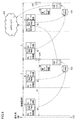
- Period control and switch> 9 to 12 are schematic views showing an example of periodic control in the control device 100 according to the embodiment. With reference to FIGS. 9 to 12, the periodic control and the securing of free time for the system service processing unit 185 will be described.
- FIG. 9 shows an I / O processing unit 50, a logic processing unit 41 having a database writing unit 43 (abbreviated as DB writing unit 43 in the figure), a motion processing unit 42, and a control application processing unit 30.
- DB writing unit 43 database writing unit 43
- FIG. 9 shows an example in which the system service processing unit 185 and the system service processing unit 185 are executed sequentially.
- Each of these processing units is treated as a "task" in the control device 100.
- a task is a basic unit to be controlled for allocating resources (computing resources) including a processor 102 of a control device 100, and one or a plurality of programs to be executed are registered or set in each task.
- the task includes, for example, a primary task, a secondary task, and a system service task.
- the primary task includes a program having the highest execution priority (hereinafter, also simply referred to as "priority") executed by the processor 102 of the control device 100.
- the primary task includes an I / O processing unit 50, a logic processing unit 41, and a motion processing unit 42.
- the primary task is guaranteed to be executed in each control cycle T.
- the secondary task is a task whose execution cycle is guaranteed although it has a lower priority than the primary task, and includes, for example, the control application processing unit 30.
- the control application processing unit 30 of the secondary task is executed, for example, in a cycle that is an integral multiple of the control cycle T.
- the control application processing unit 30 is executed, for example, every cycle 2T, that is, every double control cycle T.
- the interpreter 31 of the control application processing unit 30 executed with low priority suspends the interpretation of the control application program 1542 before the predetermined control application synchronization cycle (cycle 2T) arrives.
- the pause timing includes the timing when all the code of the control application program 1542 has been interpreted and executed.
- the interpreter 31 updates the data shared with the program processing unit 40 every 2T, which is a synchronization cycle (that is, a control application synchronization cycle) which is an integral multiple of the control cycle T.
- the input data and the output data acquired from the field side may also be updated (data synchronization).
- the system service task has a lower priority than the secondary task and is executed in the free time of the processor 102 in the control cycle T.
- the system service task includes the system service processing unit 185.
- the control device 100 can execute the system service task within the range that guarantees the execution cycle of the primary task and the secondary task.
- the scheduler 25 realizes task cycle control by managing the execution timing of these tasks (each program included in the tasks) according to the priority. More specifically, the scheduler 25 causes the processor 102 to execute the program of each task according to the priority by allocating the resource to the program of each task at a timely timing and period.
- the execution time of the control application processing unit 30 becomes long.
- the pause timing described above may coincide with the end of the cycle 2T.
- an event of 231 with no free time occurs in the control cycle T.
- the database writing unit 43 since the event of no free time 231 occurred in the immediately preceding cycle 2T, the database writing unit 43 does not read data from the NBQ 158 until the free time in the subsequent cycle 2T. Data is stored in NBQ158. Therefore, since the NBQ 158 stores data over the control cycle T of N times (N ⁇ 4) up to the free time in the subsequent cycle 2T, by the time the free time in the subsequent cycle 2T arrives, the data is stored. Memory can be exhausted.
- control device 100 is provided with a predetermined type of instruction code of the control application program 1542 in order to secure the execution time of the system service processing unit 185 in the control cycle T, that is, to avoid memory exhaustion. Switch the task when it detects that it has been executed.
- the interpreter 31 executes a predetermined type of instruction code of the control application program 1542. Detects whether or not it has been done.
- the program analysis unit 34 sets the flag F to True.
- the switching unit 26 of the scheduler 25 detects that the flag F has been changed from False to True, the switching unit 26 switches the task (switch 45). Specifically, the switching unit 26 causes the processor 102 to suspend (interrupt 232) the execution of the control application processing unit 30 and start the system service processing unit 185 to execute.
- the process for the program analysis unit 34 to detect that a predetermined type of instruction code has been executed will be described later.
- the control device 100 secures the free time 233 by the interruption 232 of the execution of the control application processing unit 30, and the system service processing unit 185 in the secured free time 233.
- the read processing unit 183 reads data from the NBQ 158. As a result, the memory exhaustion of NBQ158 can be avoided.
- control device 100 implements the task switch as shown in FIG. 12 based on the value of the variable MR indicating the remaining memory of the NBQ 158 detected by the remaining amount monitoring unit 44 so that the memory exhaustion can be avoided. ..
- the primary task includes an I / O processing unit 50, a logic processing unit 41, and a motion processing unit 42.
- the logic processing unit 41 includes a remaining amount monitoring unit 44 and a control application processing unit 301 in addition to the DB writing unit 43.
- the remaining amount monitoring unit 44 is realized by executing the remaining amount monitoring program 1544 called during the execution of the IEC program 1541.
- the control application processing unit 301 is realized by executing a predetermined instruction code described in the IEC program 1541. A predetermined instruction code for realizing the control application processing unit 301 will be described later.
- the remaining amount monitoring program 1544 may also be configured to include the remaining amount monitoring instruction code described in the IEC program 1541.
- the remaining amount monitoring unit 44 detects the remaining amount of memory (unit is, for example, percentage) of NBQ158, compares the detected remaining amount of memory with the threshold value, and sets a value based on the comparison result in the variable MR.
- the threshold value includes a warning threshold value and a monitoring threshold value indicating a value larger than the warning threshold value.
- the remaining amount monitoring unit 44 sets the variable MR to "Normal” so as to indicate that the memory remaining amount has a sufficient margin, and performs the above comparison. If the result shows (monitoring threshold ⁇ remaining memory> warning threshold), set the variable MR "Monitoring" to indicate that there is a possibility of memory exhaustion, and the above comparison result is (remaining memory ⁇ warning).
- "Warning" is set in the variable MR so as to indicate that the memory has been exhausted.
- the switching unit 26 does not execute the task switch 45 when the variable MR indicates “Normal” or “Monitoring” in the control cycle T, but implements the switch 45 when it indicates “Warning”. Specifically, the switching unit 26 causes the processor 102 to suspend the execution of the control application processing unit 30 being executed in the control cycle T 232, executes the switch 45, and starts the system service processing unit 185. As a result, the control device 100 can execute the system service processing unit 185 in the free time 233 caused by the interruption 232 in the control cycle T and read the data from the NBQ 158. As a result, the control device 100 can eliminate the memory exhaustion of the NBQ 158.
- the remaining amount monitoring unit 44 typically detects the remaining amount of memory of the NBQ 158 at the start of execution of the IEC program 1541 having the control cycle T. As a result, in each control cycle T, the variable MR is set to a value based on the latest remaining memory amount. Therefore, the switching unit 26 can determine whether or not to execute the switch 45 based on the most recently detected remaining memory amount.
- FIG. 13 is a flowchart schematically showing the processing of the control application processing unit 30 according to the embodiment.
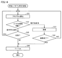
- FIG. 14 is a flowchart showing the processing of the program analysis unit 34 according to the embodiment.
- FIG. 15 is a table showing the correspondence between the types of instruction codes and the instruction codes according to the embodiment.
- FIG. 16 is a flowchart schematically showing the processing of the scheduler 25 according to the embodiment.
- control application processing unit 30 executes variable synchronization processing (step S1).
- the variable synchronization process is included in the process of the data synchronization 230 described above. Further, the control application processing unit 30 sets the flag F to False as an initial value in step S1.
- step S3 When the processing of the control application processing unit 30 is started, the program analysis unit 34 of the interpreter 31 program-analyzes the control application program 1542 (step S3). The details of the program analysis process will be described with reference to FIG.
- the control application processing unit 30 outputs the execution result of the control application program 1542 (step S5).
- the control application processing unit 30 stores the intermediate code 33 in the buffer 32 as an execution result.
- the control application processing unit 30 outputs a completion notification when the execution of the control application program 1542 is completed (step S7).
- the processing of the program analysis unit 34 of FIG. 14 is carried out with reference to the table of FIG.
- the table of FIG. 15 is stored, for example, in storage.
- the table has a predetermined type of instruction code (condition waiting, operation system) and an instruction code corresponding to the type in association with each type.
- the condition waiting instruction code includes a waiting instruction code and a waiting instruction code described by using a code for determining whether the waiting condition is satisfied.
- the conditional waiting instruction code is an instruction code instructing not to execute the instruction code of the program on the next line until the waiting conditions are met, that is, until it is determined that the waiting conditions are satisfied.
- this instruction code for example, an instruction code such as an IF statement or a WHILE statement described using a wait condition and an instruction code such as WAIT, TIMER, SLEEP described using the passage of a predetermined time as a wait condition are used. include.
- the condition waiting instruction code includes, for example, an instruction code that defines a digital input signal input waiting state, timer processing, in-position check waiting state, etc. on the control application program 1542.
- the operation system instruction code is an instruction code that generates an intermediate code 33 when executed, and includes, for example, instruction codes related to orbit generation such as MOVE, MOVEC, and MOVES.
- the intermediate code 33 generated by executing the operation system instruction code enables the operation of the command value over a plurality of control cycles T.
- the motion processing unit 42 intermediates.
- the code 33 is read from the buffer 32, and the command value is periodically calculated over a period of a plurality of control cycles T.
- the number of continuous control cycles T defined by the command values that can be generated from one intermediate code 33 can be made different for each instruction code of the operation system instruction code.
- the motion processing unit 42 uses the intermediate code 33 of the buffer 32 to set a command value for a period over a plurality of continuous control cycles T thereafter. Can be calculated.
- the interpreter 31 reads the program line by line from the first line of the control application program 1542 (step S31), and the program analysis unit 34 describes the types of instruction codes of the read program in the table of FIG. (Step S33).
- step S33 When the program analysis unit 34 analyzes the instruction code and determines that it is an operation system instruction code based on the analysis result (“operation system instruction” in step S33), the program analysis unit 34 executes an operation according to the instruction code. Then, the intermediate code 33, which is the calculation result, is calculated (step S37).
- step S39 determines whether or not the calculation is completed (step S39) and determines that the calculation is not completed (NO in step S39)
- step S31 determines that the calculation is not completed (NO in step S39)
- step S31 determines that the calculation is not completed (NO in step S39)
- the process proceeds to step S31, and the interpreter 31 moves to the next line.
- step S33 When the program analysis unit 34 analyzes the instruction code and determines that the instruction code is a condition-waiting instruction code based on the analysis result (“condition-waiting instruction” in step S33), the program analysis unit 34 executes an operation according to the instruction code. Then, it is determined whether or not the condition is satisfied (the condition is satisfied) based on the calculation result (step S35). When the program analysis unit 34 determines that the conditions are met (YES in step S35), the program proceeds to step S31, and the interpreter 31 reads the program on the next line. When the program analysis unit 34 determines that the conditions are not met (NO in step S35), that is, when the control application processing unit 30 determines that the condition is in a waiting state, the process proceeds to step S40.
- step S40 the program analysis unit 34 sets True in the flag F.
- the scheduler 25 determines whether or not to receive a notification from the program analysis unit 34 that the flag F has been changed from False to True (step S41).
- the scheduler 25 executes a normal scheduling process (step S47). That is, the scheduler 25 causes the processor 102 to execute the tasks in the order based on the priority.
- the switching unit 26 switches the task. That is, the switching unit 26 causes the processor 102 to suspend the execution of the control application processing unit 30 and start the execution of the system service processing unit 185 (step S43).
- step S45 determines whether or not the next control cycle T has arrived.
- the scheduler 25 repeats the process of step S45 while determining that the next control cycle T has not arrived (NO in step S45), but determines that the next control cycle T has arrived (YES in step S45). ),
- the process of step S47 is executed, and it is determined whether or not the scheduling process is completed (step S49).
- step S49 When the scheduler 25 determines that the task scheduling process has not been completed (NO in step S49), it returns to step S41, but when it determines that the task scheduling process has been completed (YES in step S49), it performs a series of processes. finish.
- the switching unit 26 interrupts the execution of the control application processing unit 30 by the processor 102 and starts the system service processing unit 185. By doing so, data can be read from the NBQ 158 and memory exhaustion can be avoided.
- the buffer 32 can store the intermediate code 33 that enables the calculation of the command value over the plurality of control cycles T, even if the execution of the control application processing unit 30 is interrupted, the interruption is caused by the motion processing unit 42. Does not affect the calculation of the command value of.
- FIG. 17 is a diagram schematically showing a part of the control application program 1542 according to the embodiment.
- FIG. 18 is a flowchart schematically showing the processing of the switching unit 26 according to the embodiment.
- FIG. 19 is a diagram schematically showing an example of an instruction code executed by the control application processing unit 301 according to the embodiment.
- the instruction code executed by the control application processing unit 301 shown in FIG. 19 is an instruction executed when the execution of the control application processing unit 30 (that is, the control application program 1542) is interrupted by the switch 45 in the IEC program 1541. Includes code.
- This instruction code is an instruction code for executing a process related to real-time control of the controlled object, and is typically a code corresponding to the instruction code of the control application program 1542, and generates an intermediate code. Includes instruction code.
- the control application program 1542 includes the instruction code 1600.
- Sign (X) indicates the condition that "the variable MR indicates” Warning "”. Therefore, while the variable MR indicates "Warning", the waiting state in which the next instruction code of the control application program 1542 is not executed is used.
- This waiting state includes a state of waiting until the variable MR is changed to "Normal” or "Monitoring”.
- the wait state includes a state of waiting until the memory exhaustion of the NBQ 158 is resolved, that is, a state of waiting until data is read from the NBQ 158 by the read processing unit 183 and a sufficient free area is created.
- the switching unit 26 causes the processor 102 to interrupt the execution of the control application processing unit 30 and start the system service processing unit 185 to start the execution, thereby eliminating the memory exhaustion. be able to.
- the instruction code 1600 corresponds to the type of instruction code waiting for the condition shown in FIG.
- the remaining amount monitoring unit 44 detects the remaining amount of memory (step S61), and compares the detected remaining amount of memory with the warning threshold value and the monitoring threshold value (step S63, step S67). Set a value based on the result of comparison in the variable MR.
- step S63 When the value of the variable MR indicates “Warning” (YES in step S63), the switching unit 26 executes warning processing (step S65), and when the value of the variable MR indicates “Monitoring” (step S63). NO, YES in step S67), and monitoring processing (step S69) is performed.
- step S65 When the value of the variable MR shows neither “Warning” nor “Monitoring” (NO in step S67), that is, when the variable MR shows “Normal”, the process ends.
- step S65 An example of the warning process (step S65) and the monitoring process (step S69) will be described with reference to FIG.
- the program of the control application processing unit 301 is described in, for example, a ladder program in the IEC program 1541.
- FBs (function blocks) 1546 and 1548 correspond to some instruction codes of the control application program 1542.
- the switching unit 26 outputs the signal X1 to the program processing unit 40.
- the block 1545 is turned on and the FB 1546 is executed.
- FB1548 is executed when the condition block 1547 of the IF statement "variable MR indicates" Warning "" is turned on, that is, when the condition of the IF statement is satisfied.
- the FB 1546 in FIG. 19 When executed, the FB 1546 in FIG. 19 outputs, for example, an intermediate code 33 over N consecutive control cycles T. Further, when executed, the FB1548 outputs, for example, intermediate codes 33 over M consecutive control cycles T (where M ⁇ N).
- the control cycle T By executing the control application processing unit 301 of the primary task, the intermediate code 33 for calculating the command value over the plurality of control cycles T can be calculated. Therefore, it can be guaranteed that the intermediate code required for calculating the command value is calculated prior to the execution of the motion processing unit 42 in the primary task of each control cycle T.
- program of the control application processing unit 301 shown in FIG. 19 may be executed in the primary task when the switch 45 is executed according to the flag F.
- FIG. 20 is a diagram for explaining an example of an application using time series data stored in the time series database 180 of the control device 100 according to the embodiment.
- the manufacturing execution system 400 realizes quality traceability and the like by using the time series data stored in the time series database 180 of the control device 100. Specifically, based on the manufacturing data included in the time-series data stored in the time-series database 180, it is determined which work (manufacturing) the time-series data is associated with. By arranging the time-series data for each of the discriminated works in the order of the time of occurrence, the state of each work at the time of manufacturing can be grasped. For example, FIG. 20 shows an example in which a plurality of time series data are stored in association with the work of “product number 001” and a plurality of time series data are stored in association with the work of “product number 002”. ..
- the manufacturing execution system 400 may generate information related to quality traceability based on the time series data stored in the time series database 180 of the control device 100.
- the IoT service 450 realizes so-called big data analysis.
- the IoT service 450 outputs not only time-series data from the control device 100 that controls the manufacturing device / equipment 11, but also time-series data from another manufacturing device / equipment 11.
- the IoT service 450 performs various analyzes on time series data from one or more manufacturing equipment / equipment. As an example of such an analysis, a time series analysis 460 is shown.
- One or more processors constituting the system that provides the IoT service 450 executes the time series analysis 460.
- one or more processors perform preprocessing 462 on the time series data.
- pre-processing 462 one or more processors execute a process of extracting a feature amount or the like from time-series data stored in the storage to lower the dimension, a process of excluding abnormal values and outliers, and the like.
- processors execute the analysis process 464 on the time series data in which the preprocess 462 is performed.
- One or more processors generate a model for the manufacturing equipment / equipment to be controlled by performing modeling 466 based on the result of the analysis process 464.
- One or more processors store the generated model (a set of functions or parameters) in storage.
- one or more processors execute prediction processing 468 such as occurrence of abnormality and progress of deterioration based on the generated model.
- one or more processors may visually output the result of the prediction process 468 to a display or the like using a graph, a table, or the like (visualization process 470).
- the IoT service 450 performs data analysis based on the time series data stored in the time series database 180 of the control device 100. It is assumed that such an IoT service 450 is typically implemented in an environment having sufficient computing resources on the cloud. Therefore, hidden characteristics can be found by using a large amount of time series data.
- the time relationship between the observed values in the time series data can be determined more precisely by associating the time and counter information, so that more accurate and meaningful analysis can be realized. For example, when generating a model, it is important to search for a hidden causal relationship between observed values, but such a causal relationship may not be found due to a time lag. In the system according to the present embodiment, since the temporal relationship between the observed values can be determined more accurately in the preprocessing, more accurate model generation can be realized.
- AI Artificial Intelligence processing 196
- supervised machine learning may be performed to detect in advance abnormalities and deterioration tendencies that occur in the manufacturing equipment or equipment to be controlled.
- the AI process 196 generated a feature amount from one or a plurality of observed values included in the time-series data stored in the time-series database 180 of the control device 100, and statistically processed the generated feature amount. Above, it is retained as training data. Then, the AI process 196 calculates the degree to which the input observation value deviates from the learning data when some new observation value is input, and also calculates the degree of deviation to the calculated degree of deviation. Based on this, the presence or absence of abnormalities and the tendency of deterioration are judged.
- AI processing 196 By mounting such AI processing 196 in the control device 100, it is possible to detect abnormalities and deterioration tendencies that occur in the manufacturing device or equipment to be controlled in substantially real time.
- a storage unit (108) that stores a plurality of programs
- a scheduler (25) that manages a program that causes the processor to execute according to a priority within a predetermined cycle, and includes a scheduler (25).
- the plurality of programs in the storage unit A first program (1541) for real-time control processing of the controlled object, which is the program having the highest execution priority executed by the processor in the cycle, and A second program (1542) for related processing related to the real-time control, which is a program having a lower execution priority than the first program.
- It includes a third program (190, 191) of a system service that has a lower execution priority than the second program and is executed when there is free time in the processor in the cycle.
- the scheduler If the execution of the second program is started within the cycle and then a predetermined type of instruction code is executed in the second program, the processor interrupts the execution of the second program.
- a control device including a switching unit (26) for starting execution of the third program.
- the real-time control process includes a process of generating a command value to the control target based on an intermediate code generated by the related process.
- the control device further A data generation unit (43) that generates data for constructing a record to be stored in the time series database for each cycle, and a data generation unit (43).
- a non-blocking queue (158) formed on a volatile main storage device for sequentially storing data generated by the data generation unit is provided.
- the system service The control device according to configuration 5, further comprising a process (183) of reading the data from the non-blocking queue and storing it in the time series database.
- the control device further A remaining amount monitoring unit (44) for monitoring the remaining amount of memory in the non-blocking queue is provided.
- the switching unit is The control according to configuration 6 or 7, wherein the processor interrupts the execution of the second program being executed and starts the execution of the third program based on the result of the comparison between the remaining memory amount and the threshold value. Device.
- the scheduler program If the execution of the second program is started within the cycle and then a predetermined type of instruction code is executed in the second program, the processor interrupts the execution of the second program.
- the control device is A first program (1541) for real-time control processing of the controlled object, which is the program having the highest execution priority executed by the processor in a predetermined cycle, and A second program (1542) for related processing related to the real-time control, which is a program having a lower execution priority than the first program. It includes a third program (190, 191) of a system service that has a lower execution priority than the second program and is executed when there is free time in the processor in the cycle.
- the control method is A step of managing a program that causes the processor to execute according to the priority within the cycle is provided.
- the management step is within the cycle A step (S33) of starting execution of the second program and then determining whether or not a predetermined type of instruction code is executed in the second program. Based on the determination, the control method includes, in the case of the case, a step (S43) of causing the processor to suspend the execution of the second program and start the execution of the third program.
Landscapes
- Engineering & Computer Science (AREA)
- Software Systems (AREA)
- Theoretical Computer Science (AREA)
- Physics & Mathematics (AREA)
- General Physics & Mathematics (AREA)
- General Engineering & Computer Science (AREA)
- Automation & Control Theory (AREA)
- Programmable Controllers (AREA)
Abstract
Description
上述の開示によれば、制御装置は、内部に時系列データベースを備えることができる。
図1は、適用例を模式的に示す図である。図1を参照して、本開示が適用される場面の一例について説明する。図1を参照して、FAの生産現場に備えられる制御対象を制御する制御装置100は、プロセッサ102と、HDD(Hard Disc Drive)などの二次記憶装置108と、スケジューラ25と、時系列データベース180と、を備える。制御装置100は、PLCなどのコントローラを含む。「制御対象」は、FAの生産ラインに備えられて制御の対象となる機械または設備、センサなどを含む。機械または設備は、ロボット、テーブル、コンベアなどのメカニカル機構を含む。
まず、本実施の形態に係る制御装置を含む制御システム1の全体構成例について説明する。
<C.制御装置のハードウェア構成例>
実施の形態に係る制御装置100のハードウェア構成例について説明する。
次に、実施の形態に係る制御装置100のソフトウェア構成例について説明する。
図5は、実施の形態に係る制御装置100の機能構成の一例を示す模式図である。図5を参照して、制御装置100は、制御アプリケーション処理部30と、プログラム処理部40と、I/O処理部50と、スケジューラ25と、切替部26と、フィールドネットワークインターフェイス55と、上位ネットワークインターフェイス51と、システムサービス処理部185とを含む。図5の制御装置100は、これらコンポーネントに関連づけて、さらに、NBQ158と、時系列データベース180とを含む。
実施の形態では、NBQ158は例えば、メモリ(揮発性の主記憶装置106)上に用意されるから、NBQ158のメモリ容量(サイズ)は制限される。したがって、プロセッサ102の空き時間がないために、システムサービス処理部185にプロセッサ102を含むリソースの使用権が与えられない、すなわちシステムサービス処理部185がデータベースプログラム190を実行できない場合は、NBQ158の空き領域、すなわちメモリ残量が不足することになる。つまり、NBQ158には、データベース書込部43によってデータが順次に書込まれるが、一方で読出処理部183によってNBQ158からデータは読出されないために、NBQ158にデータを書込むための空き領域が不足することになる。以下では、このようなNBQ158の空き領域の不足を「メモリ枯渇」と称する。
次に、実施の形態に係る時系列データベース180へのデータ書込み処理について説明する。
実施の形態に係る時系列データベース180に格納されるレコードのデータ構造の一例について説明する。
図9~図12は、実施の形態に係る制御装置100における周期制御の一例を示す模式図である。図9~図12を参照して、周期制御とシステムサービス処理部185のための空き時間の確保を説明する。
実施の形態では、制御周期Tにおいてシステムサービス処理部185の実行時間を確保するために、すなわちメモリ枯渇を回避できるよう、制御装置100は、制御アプリケーションプログラム1542の予め定められた種類の命令コードが実行されたことを検出したとき、タスクをスイッチする。
実施の形態では、メモリ枯渇を回避できるよう、制御装置100は、残量監視部44が検出したNBQ158のメモリ残量を示す変数MRの値に基づき、図12に示すようにタスクスイッチを実施する。
上記の(h1.タスクスイッチの一例)および(h2.タスクスイッチの他の例)のそれぞれについて、具体的な実現例を説明する。
上記の(h1.タスクスイッチの一例)の具体的な処理を、図13~図16を参照して説明する。図13は、実施の形態に係る制御アプリケーション処理部30の処理を概略的に示すフローチャートである。図14は、実施の形態に係るプログラム解析部34の処理を示すフローチャートである。図15は、実施の形態に係る命令コードの種類と命令コードの対応関係を示す表である。図16は、実施の形態に係るスケジューラ25の処理を概略的に示すフローチャートである。
図16を参照して、スケジューラ25は、フラグFがFalseからTrueに変更されたことの通知をプログラム解析部34から受信するか否かを判断する(ステップS41)。スケジューラ25は、通知を受信しないと判断すると(ステップS41でNO)、通常のスケジューリング処理を実施する(ステップS47)。すなわち、スケジューラ25は、優先度に基づく順序でプロセッサ102にタスクを実行させる。
上記の(h2.タスクスイッチの他の例)の具体的な処理を、図17と図18を参照して説明する。図17は、実施の形態に係る制御アプリケーションプログラム1542の一部を模式的に示す図である。図18は、実施の形態に係る切替部26の処理を概略的に示すフローチャートである。図19は、実施の形態に係る制御アプリケーション処理部301が実行する命令コードの一例を模式的に示す図である。
次に、実施の形態に係る制御装置100が生成および出力する時系列データを用いた応用例について説明する。
上述したような本実施の形態は、以下のような技術思想を含む。
制御対象(8)を制御する制御装置(100)であって、
プロセッサ(102)と、
複数のプログラムを格納する記憶部(108)と、
予め定められた周期内で、前記プロセッサに優先度に従い実行させるプログラムを管理するスケジューラ(25)と、を含み、
前記記憶部の前記複数のプログラムは、
前記周期において前記プロセッサで実行される最も実行の優先度が高いプログラムであって、前記制御対象のリアルタイム制御処理のための第1のプログラム(1541)と、
前記第1のプログラムより実行の優先度が低いプログラムであって、前記リアルタイム制御に関連する関連処理のための第2のプログラム(1542)と、
前記第2のプログラムより実行の優先度が低く、前記周期においてプロセッサの空き時間がある場合に実行されるシステムサービスの第3のプログラム(190、191)とを含み、
前記スケジューラは、
前記周期内において、前記第2のプログラムの実行を開始し、その後に前記第2のプログラムにおいて予め定められた種類の命令コードが実行された場合、前記プロセッサに前記第2のプログラムの実行を中断させ前記第3のプログラムを実行開始させる切替部(26)を含む、制御装置。
前記リアルタイム制御処理は、前記関連処理により生成された中間コードに基づき前記制御対象への指令値を生成する処理を含み、
前記予め定められた種類の命令コードは、実行されると複数周期にわたる前記中間コードを生成する命令コードを含む、構成1に記載の制御装置。
前記予め定められた種類の命令コードは、待ち合わせ条件と当該待ち合わせ条件が満たされるかを判断するコードを用いて記述される待ち合わせ命令コードを含む、構成1または2に記載の制御装置。
前記第2のプログラムは、インタプリタ言語で記述されたプログラムを含む、構成1から3のいずれか1に記載の制御装置。
前記システムサービスは、
前記制御対象に関するデータを含むレコードを時系列に格納する時系列データベース(180)の処理を含む、構成1から4のいずれか1に記載の制御装置。
前記制御装置は、さらに、
前記周期毎に、前記時系列データベースへ格納すべきレコードを構成するためのデータを生成するデータ生成部(43)と、
前記データ生成部により生成されるデータを順次格納する、揮発性の主記憶装置上に形成されるノンブロッキングキュー(158)と、を備え、
前記システムサービスは、
前記ノンブロッキングキューから前記データを読み出し、前記時系列データベースに格納する処理(183)を含む、構成5に記載の制御装置。
前記制御装置が前記時系列データベースを備える、構成6に記載の制御装置。
前記制御装置は、さらに、
前記ノンブロッキングキューのメモリ残量を監視する残量監視部(44)を備え、
前記切替部は、
前記メモリ残量と閾値の比較の結果に基づき、前記プロセッサに、実行中の前記第2のプログラムの実行を中断させ、前記第3のプログラムの実行を開始させる、構成6または7に記載の制御装置。
前記第1のプログラムは、前記第2のプログラムの実行が中断した場合に実行される、前記関連処理の命令コード(301)を含む、構成1から8のいずれか1に記載の制御装置。
制御対象(8)を制御するためのプロセッサ(102)を有する制御装置(100)で実行されるプログラムであって、
予め定められた周期内で、前記プロセッサに優先度に従い実行させるプログラムを管理するスケジューラプログラム(170)と、
前記周期において前記プロセッサで実行される最も実行の優先度が高いプログラムであって、前記制御対象のリアルタイム制御処理のための第1のプログラム(1541)と、
前記第1のプログラムより実行の優先度が低いプログラムであって、前記リアルタイム制御に関連する関連処理のための第2のプログラム(1542)と、
前記第2のプログラムより実行の優先度が低く、前記周期においてプロセッサの空き時間がある場合に実行されるシステムサービスの第3のプログラム(190、191)とを備え、
前記スケジューラプログラムは、
前記周期内において、前記第2のプログラムの実行を開始し、その後に前記第2のプログラムにおいて予め定められた種類の命令コードが実行された場合、前記プロセッサに前記第2のプログラムの実行を中断させ前記第3のプログラムを実行開始させるスイッチプログラム(171)を含む、プログラム。
制御対象(8)を制御するためのプロセッサ(102)を有する制御装置(100)を制御する制御方法であって、
前記制御装置は、
予め定められた周期において前記プロセッサで実行される最も実行の優先度が高いプログラムであって、前記制御対象のリアルタイム制御処理のための第1のプログラム(1541)と、
前記第1のプログラムより実行の優先度が低いプログラムであって、前記リアルタイム制御に関連する関連処理のための第2のプログラム(1542)と、
前記第2のプログラムより実行の優先度が低く、前記周期においてプロセッサの空き時間がある場合に実行されるシステムサービスの第3のプログラム(190、191)とを備え、
前記制御方法は、
前記周期内で、前記プロセッサに優先度に従い実行させるプログラムを管理するステップを、備え、
前記管理するステップは、
前記周期内において、
前記第2のプログラムの実行を開始し、その後に前記第2のプログラムにおいて予め定められた種類の命令コードが実行されるか否かを判断するステップ(S33)と、
前記判断に基づき、場合、前記プロセッサに前記第2のプログラムの実行を中断させ前記第3のプログラムを実行開始させるステップ(S43)とを含む、制御方法。
Claims (11)
- 制御対象を制御する制御装置であって、
プロセッサと、
複数のプログラムを格納する記憶部と、
予め定められた周期内で、前記プロセッサに優先度に従い実行させるプログラムを管理するスケジューラと、を含み、
前記記憶部の前記複数のプログラムは、
前記周期において前記プロセッサで実行される最も実行の優先度が高いプログラムであって、前記制御対象のリアルタイム制御処理のための第1のプログラムと、
前記第1のプログラムより実行の優先度が低いプログラムであって、前記リアルタイム制御に関連する関連処理のための第2のプログラムと、
前記第2のプログラムより実行の優先度が低く、前記周期においてプロセッサの空き時間がある場合に実行されるシステムサービスの第3のプログラムとを含み、
前記スケジューラは、
前記周期内において、前記第2のプログラムの実行を開始し、その後に前記第2のプログラムにおいて予め定められた種類の命令コードが実行された場合、前記プロセッサに前記第2のプログラムの実行を中断させ前記第3のプログラムを実行開始させる切替部を含む、制御装置。 - 前記リアルタイム制御処理は、前記関連処理により生成された中間コードに基づき前記制御対象への指令値を生成する処理を含み、
前記予め定められた種類の命令コードは、実行されると複数周期にわたる前記中間コードを生成する命令コードを含む、請求項1に記載の制御装置。 - 前記予め定められた種類の命令コードは、待ち合わせ条件と当該待ち合わせ条件が満たされるかを判断するコードを用いて記述される待ち合わせ命令コードを含む、請求項1または2に記載の制御装置。
- 前記第2のプログラムは、インタプリタ言語で記述されたプログラムを含む、請求項1から3のいずれか1項に記載の制御装置。
- 前記システムサービスは、
前記制御対象に関するデータを含むレコードを時系列に格納する時系列データベースの処理を含む、請求項1から4のいずれか1項に記載の制御装置。 - 前記制御装置は、さらに、
前記周期毎に、前記時系列データベースへ格納すべきレコードを構成するためのデータを生成するデータ生成部と、
前記データ生成部により生成されるデータを順次格納する、揮発性の主記憶装置上に形成されるノンブロッキングキューと、を備え、
前記システムサービスは、
前記ノンブロッキングキューから前記データを読み出し、前記時系列データベースに格納する処理を含む、請求項5に記載の制御装置。 - 前記制御装置が前記時系列データベースを備える、請求項6に記載の制御装置。
- 前記制御装置は、さらに、
前記ノンブロッキングキューのメモリ残量を監視する残量監視部を備え、
前記切替部は、
前記メモリ残量と閾値の比較の結果に基づき、前記プロセッサに、実行中の前記第2のプログラムの実行を中断させ、前記第3のプログラムの実行を開始させる、請求項6または7に記載の制御装置。 - 前記第1のプログラムは、前記第2のプログラムの実行が中断した場合に実行される、前記関連処理の命令コードを含む、請求項1から8のいずれか1項に記載の制御装置。
- 制御対象を制御するためのプロセッサを有する制御装置で実行されるプログラムであって、
予め定められた周期内で、前記プロセッサに優先度に従い実行させるプログラムを管理するスケジューラプログラムと、
前記周期において前記プロセッサで実行される最も実行の優先度が高いプログラムであって、前記制御対象のリアルタイム制御処理のための第1のプログラムと、
前記第1のプログラムより実行の優先度が低いプログラムであって、前記リアルタイム制御に関連する関連処理のための第2のプログラムと、
前記第2のプログラムより実行の優先度が低く、前記周期においてプロセッサの空き時間がある場合に実行されるシステムサービスの第3のプログラムとを備え、
前記スケジューラプログラムは、
前記周期内において、前記第2のプログラムの実行を開始し、その後に前記第2のプログラムにおいて予め定められた種類の命令コードが実行された場合、前記プロセッサに前記第2のプログラムの実行を中断させ前記第3のプログラムを実行開始させるスイッチプログラムを含む、プログラム。 - 制御対象を制御するためのプロセッサを有する制御装置を制御する制御方法であって、
前記制御装置は、
予め定められた周期において前記プロセッサで実行される最も実行の優先度が高いプログラムであって、前記制御対象のリアルタイム制御処理のための第1のプログラムと、
前記第1のプログラムより実行の優先度が低いプログラムであって、前記リアルタイム制御に関連する関連処理のための第2のプログラムと、
前記第2のプログラムより実行の優先度が低く、前記周期においてプロセッサの空き時間がある場合に実行されるシステムサービスの第3のプログラムとを備え、
前記制御方法は、
前記周期内で、前記プロセッサに優先度に従い実行させるプログラムを管理するステップを、備え、
前記管理するステップは、
前記周期内において、
前記第2のプログラムの実行を開始し、その後に前記第2のプログラムにおいて予め定められた種類の命令コードが実行されるか否かを判断するステップと、
前記判断に基づき、場合、前記プロセッサに前記第2のプログラムの実行を中断させ前記第3のプログラムを実行開始させるステップとを含む、制御方法。
Priority Applications (3)
| Application Number | Priority Date | Filing Date | Title |
|---|---|---|---|
| CN202080097305.2A CN115176208B (zh) | 2020-03-31 | 2020-12-17 | 控制装置、记录介质以及控制方法 |
| US17/908,134 US20230359487A1 (en) | 2020-03-31 | 2020-12-17 | Control device, non-transitory computer-readable medium, and control method |
| EP20928541.0A EP4130899A4 (en) | 2020-03-31 | 2020-12-17 | CONTROL DEVICE, PROGRAM AND CONTROL METHOD |
Applications Claiming Priority (2)
| Application Number | Priority Date | Filing Date | Title |
|---|---|---|---|
| JP2020062362A JP7380390B2 (ja) | 2020-03-31 | 2020-03-31 | 制御装置、プログラムおよび制御方法 |
| JP2020-062362 | 2020-03-31 |
Publications (1)
| Publication Number | Publication Date |
|---|---|
| WO2021199519A1 true WO2021199519A1 (ja) | 2021-10-07 |
Family
ID=77930243
Family Applications (1)
| Application Number | Title | Priority Date | Filing Date |
|---|---|---|---|
| PCT/JP2020/047256 Ceased WO2021199519A1 (ja) | 2020-03-31 | 2020-12-17 | 制御装置、プログラムおよび制御方法 |
Country Status (5)
| Country | Link |
|---|---|
| US (1) | US20230359487A1 (ja) |
| EP (1) | EP4130899A4 (ja) |
| JP (1) | JP7380390B2 (ja) |
| CN (1) | CN115176208B (ja) |
| WO (1) | WO2021199519A1 (ja) |
Families Citing this family (5)
| Publication number | Priority date | Publication date | Assignee | Title |
|---|---|---|---|---|
| DE102022103812A1 (de) * | 2022-02-17 | 2023-08-17 | WAGO Verwaltungsgesellschaft mit beschränkter Haftung | Computerimplementiertes verfahren zur zumindest teilweise automatisierten konfiguration eines feldbusses, feldbussystem, computerprogramm, computerlesbares speichermedium, trainingsdatensatz und verfahren zum trainieren eines konfigurations-ki-modells |
| EP4293437A1 (de) * | 2022-06-15 | 2023-12-20 | Schneider Electric Industries SAS | Verfahren und vorrichtung zum steuern des ablaufs von programmteilen, programmierverfahren, programmiervorrichtung |
| US20260003343A1 (en) * | 2023-03-14 | 2026-01-01 | Mitsubishi Electric Corporation | Numerical control device |
| EP4550136A1 (de) * | 2023-11-06 | 2025-05-07 | Schaeffler Technologies AG & Co. KG | Verfahren zur ausführungssteuerung von tasks in einem prozessorsystem und taskausführungssteuerung |
| CN117312117B (zh) * | 2023-11-30 | 2024-03-01 | 沐曦集成电路(杭州)有限公司 | 一种打点数据的处理方法、装置、设备及介质 |
Citations (5)
| Publication number | Priority date | Publication date | Assignee | Title |
|---|---|---|---|---|
| JP2007004334A (ja) * | 2005-06-22 | 2007-01-11 | Fuji Electric Fa Components & Systems Co Ltd | プログラマブルコントローラ |
| JP2013025353A (ja) * | 2011-07-15 | 2013-02-04 | Omron Corp | Plcのcpuユニット、plc用のシステムプログラム、plc用のシステムプログラムを格納した記録媒体、plcシステム、plcサポート装置、plcサポートプログラム、および、plcサポートプログラムを格納した記録媒体 |
| JP2018181315A (ja) * | 2017-04-07 | 2018-11-15 | オムロン株式会社 | 制御装置、制御方法および制御プログラム |
| JP2019036043A (ja) | 2017-08-10 | 2019-03-07 | オムロン株式会社 | 制御装置 |
| JP2019153144A (ja) * | 2018-03-05 | 2019-09-12 | オムロン株式会社 | 制御装置、システムプログラム、制御方法 |
Family Cites Families (13)
| Publication number | Priority date | Publication date | Assignee | Title |
|---|---|---|---|---|
| JP3826626B2 (ja) * | 1997-11-21 | 2006-09-27 | オムロン株式会社 | プログラム制御装置、プログラム制御方法、およびプログラム記録媒体 |
| JP3405696B2 (ja) * | 1999-08-19 | 2003-05-12 | インターナショナル・ビジネス・マシーンズ・コーポレーション | コンパイル装置およびその方法 |
| DE10065417B4 (de) * | 2000-12-27 | 2011-07-21 | Siemens AG, 80333 | Programmierung von zyklischen Maschinen |
| JP2004234546A (ja) * | 2003-01-31 | 2004-08-19 | Sanyo Electric Co Ltd | プログラム実行方法および装置 |
| JP4609381B2 (ja) * | 2006-06-14 | 2011-01-12 | 株式会社デンソー | 異常監視用プログラム、記録媒体及び電子装置 |
| JP4957853B1 (ja) * | 2011-03-15 | 2012-06-20 | オムロン株式会社 | Plcのcpuユニット、plc用のシステムプログラムおよびplc用のシステムプログラムを格納した記録媒体 |
| US8706262B2 (en) * | 2011-03-15 | 2014-04-22 | Omron Corporation | CPU unit of PLC, system program for PLC, and recording medium storing system program for PLC |
| JP6626240B2 (ja) * | 2014-03-13 | 2019-12-25 | オムロン株式会社 | コントローラ |
| CN103984596B (zh) * | 2014-05-19 | 2017-06-20 | 上海微小卫星工程中心 | 一种星载软件的调度方法及装置 |
| JP2018133037A (ja) * | 2017-02-17 | 2018-08-23 | オムロン株式会社 | 制御装置 |
| JP6388050B1 (ja) * | 2017-03-31 | 2018-09-12 | オムロン株式会社 | 制御装置 |
| US11301294B2 (en) * | 2017-04-07 | 2022-04-12 | Omron Corporation | Control device, control method, and control program |
| JP6950385B2 (ja) * | 2017-09-12 | 2021-10-13 | オムロン株式会社 | 制御装置および制御方法 |
-
2020
- 2020-03-31 JP JP2020062362A patent/JP7380390B2/ja active Active
- 2020-12-17 US US17/908,134 patent/US20230359487A1/en not_active Abandoned
- 2020-12-17 WO PCT/JP2020/047256 patent/WO2021199519A1/ja not_active Ceased
- 2020-12-17 CN CN202080097305.2A patent/CN115176208B/zh active Active
- 2020-12-17 EP EP20928541.0A patent/EP4130899A4/en not_active Withdrawn
Patent Citations (5)
| Publication number | Priority date | Publication date | Assignee | Title |
|---|---|---|---|---|
| JP2007004334A (ja) * | 2005-06-22 | 2007-01-11 | Fuji Electric Fa Components & Systems Co Ltd | プログラマブルコントローラ |
| JP2013025353A (ja) * | 2011-07-15 | 2013-02-04 | Omron Corp | Plcのcpuユニット、plc用のシステムプログラム、plc用のシステムプログラムを格納した記録媒体、plcシステム、plcサポート装置、plcサポートプログラム、および、plcサポートプログラムを格納した記録媒体 |
| JP2018181315A (ja) * | 2017-04-07 | 2018-11-15 | オムロン株式会社 | 制御装置、制御方法および制御プログラム |
| JP2019036043A (ja) | 2017-08-10 | 2019-03-07 | オムロン株式会社 | 制御装置 |
| JP2019153144A (ja) * | 2018-03-05 | 2019-09-12 | オムロン株式会社 | 制御装置、システムプログラム、制御方法 |
Non-Patent Citations (1)
| Title |
|---|
| See also references of EP4130899A4 |
Also Published As
| Publication number | Publication date |
|---|---|
| JP2021163030A (ja) | 2021-10-11 |
| CN115176208A (zh) | 2022-10-11 |
| JP7380390B2 (ja) | 2023-11-15 |
| EP4130899A1 (en) | 2023-02-08 |
| EP4130899A4 (en) | 2024-05-01 |
| US20230359487A1 (en) | 2023-11-09 |
| CN115176208B (zh) | 2025-06-24 |
Similar Documents
| Publication | Publication Date | Title |
|---|---|---|
| JP7380390B2 (ja) | 制御装置、プログラムおよび制御方法 | |
| JP6388050B1 (ja) | 制御装置 | |
| US10606246B2 (en) | Control device and control method with various command values in a shared memory providing access to various program execution and command value operation parts in each control cycle | |
| JP6903275B2 (ja) | 制御装置および制御方法 | |
| EP3373087B1 (en) | Control device and program | |
| CN110402430B (zh) | 控制装置、控制方法以及记录介质 | |
| EP3336637A1 (en) | Control system, control program, and control method | |
| US11301294B2 (en) | Control device, control method, and control program | |
| US20190095246A1 (en) | Support device and non-transitory storage medium | |
| JP2018173883A (ja) | 制御装置、制御プログラム、制御システム、および制御方法 | |
| EP3376320A1 (en) | Control device | |
| EP3457239B1 (en) | Control device and control method | |
| WO2020100548A1 (ja) | 制御システムおよび制御装置 | |
| WO2021095466A1 (ja) | 制御装置 | |
| EP4703819A1 (en) | Control device and program | |
| JP2024157672A (ja) | 制御装置およびプログラム |
Legal Events
| Date | Code | Title | Description |
|---|---|---|---|
| 121 | Ep: the epo has been informed by wipo that ep was designated in this application |
Ref document number: 20928541 Country of ref document: EP Kind code of ref document: A1 |
|
| NENP | Non-entry into the national phase |
Ref country code: DE |
|
| ENP | Entry into the national phase |
Ref document number: 2020928541 Country of ref document: EP Effective date: 20221031 |
|
| WWG | Wipo information: grant in national office |
Ref document number: 202080097305.2 Country of ref document: CN |
|
| WWW | Wipo information: withdrawn in national office |
Ref document number: 2020928541 Country of ref document: EP |