WO2021199595A1 - 電源装置及びこれを備える車両並びに蓄電装置 - Google Patents
電源装置及びこれを備える車両並びに蓄電装置 Download PDFInfo
- Publication number
- WO2021199595A1 WO2021199595A1 PCT/JP2021/001787 JP2021001787W WO2021199595A1 WO 2021199595 A1 WO2021199595 A1 WO 2021199595A1 JP 2021001787 W JP2021001787 W JP 2021001787W WO 2021199595 A1 WO2021199595 A1 WO 2021199595A1
- Authority
- WO
- WIPO (PCT)
- Prior art keywords
- power supply
- cover
- supply device
- battery
- power
- Prior art date
- Legal status (The legal status is an assumption and is not a legal conclusion. Google has not performed a legal analysis and makes no representation as to the accuracy of the status listed.)
- Ceased
Links
Images





Classifications
-
- H—ELECTRICITY
- H01—ELECTRIC ELEMENTS
- H01M—PROCESSES OR MEANS, e.g. BATTERIES, FOR THE DIRECT CONVERSION OF CHEMICAL ENERGY INTO ELECTRICAL ENERGY
- H01M50/00—Constructional details or processes of manufacture of the non-active parts of electrochemical cells other than fuel cells, e.g. hybrid cells
- H01M50/30—Arrangements for facilitating escape of gases
- H01M50/35—Gas exhaust passages comprising elongated, tortuous or labyrinth-shaped exhaust passages
- H01M50/367—Internal gas exhaust passages forming part of the battery cover or case; Double cover vent systems
-
- H—ELECTRICITY
- H01—ELECTRIC ELEMENTS
- H01M—PROCESSES OR MEANS, e.g. BATTERIES, FOR THE DIRECT CONVERSION OF CHEMICAL ENERGY INTO ELECTRICAL ENERGY
- H01M10/00—Secondary cells; Manufacture thereof
- H01M10/42—Methods or arrangements for servicing or maintenance of secondary cells or secondary half-cells
- H01M10/44—Methods for charging or discharging
-
- H—ELECTRICITY
- H01—ELECTRIC ELEMENTS
- H01M—PROCESSES OR MEANS, e.g. BATTERIES, FOR THE DIRECT CONVERSION OF CHEMICAL ENERGY INTO ELECTRICAL ENERGY
- H01M50/00—Constructional details or processes of manufacture of the non-active parts of electrochemical cells other than fuel cells, e.g. hybrid cells
- H01M50/10—Primary casings; Jackets or wrappings
- H01M50/147—Lids or covers
- H01M50/155—Lids or covers characterised by the material
- H01M50/157—Inorganic material
- H01M50/159—Metals
-
- H—ELECTRICITY
- H01—ELECTRIC ELEMENTS
- H01M—PROCESSES OR MEANS, e.g. BATTERIES, FOR THE DIRECT CONVERSION OF CHEMICAL ENERGY INTO ELECTRICAL ENERGY
- H01M50/00—Constructional details or processes of manufacture of the non-active parts of electrochemical cells other than fuel cells, e.g. hybrid cells
- H01M50/20—Mountings; Secondary casings or frames; Racks, modules or packs; Suspension devices; Shock absorbers; Transport or carrying devices; Holders
- H01M50/204—Racks, modules or packs for multiple batteries or multiple cells
- H01M50/207—Racks, modules or packs for multiple batteries or multiple cells characterised by their shape
- H01M50/209—Racks, modules or packs for multiple batteries or multiple cells characterised by their shape adapted for prismatic or rectangular cells
-
- H—ELECTRICITY
- H01—ELECTRIC ELEMENTS
- H01M—PROCESSES OR MEANS, e.g. BATTERIES, FOR THE DIRECT CONVERSION OF CHEMICAL ENERGY INTO ELECTRICAL ENERGY
- H01M50/00—Constructional details or processes of manufacture of the non-active parts of electrochemical cells other than fuel cells, e.g. hybrid cells
- H01M50/20—Mountings; Secondary casings or frames; Racks, modules or packs; Suspension devices; Shock absorbers; Transport or carrying devices; Holders
- H01M50/249—Mountings; Secondary casings or frames; Racks, modules or packs; Suspension devices; Shock absorbers; Transport or carrying devices; Holders specially adapted for aircraft or vehicles, e.g. cars or trains
-
- H—ELECTRICITY
- H01—ELECTRIC ELEMENTS
- H01M—PROCESSES OR MEANS, e.g. BATTERIES, FOR THE DIRECT CONVERSION OF CHEMICAL ENERGY INTO ELECTRICAL ENERGY
- H01M50/00—Constructional details or processes of manufacture of the non-active parts of electrochemical cells other than fuel cells, e.g. hybrid cells
- H01M50/20—Mountings; Secondary casings or frames; Racks, modules or packs; Suspension devices; Shock absorbers; Transport or carrying devices; Holders
- H01M50/262—Mountings; Secondary casings or frames; Racks, modules or packs; Suspension devices; Shock absorbers; Transport or carrying devices; Holders with fastening means, e.g. locks
-
- H—ELECTRICITY
- H01—ELECTRIC ELEMENTS
- H01M—PROCESSES OR MEANS, e.g. BATTERIES, FOR THE DIRECT CONVERSION OF CHEMICAL ENERGY INTO ELECTRICAL ENERGY
- H01M50/00—Constructional details or processes of manufacture of the non-active parts of electrochemical cells other than fuel cells, e.g. hybrid cells
- H01M50/20—Mountings; Secondary casings or frames; Racks, modules or packs; Suspension devices; Shock absorbers; Transport or carrying devices; Holders
- H01M50/262—Mountings; Secondary casings or frames; Racks, modules or packs; Suspension devices; Shock absorbers; Transport or carrying devices; Holders with fastening means, e.g. locks
- H01M50/264—Mountings; Secondary casings or frames; Racks, modules or packs; Suspension devices; Shock absorbers; Transport or carrying devices; Holders with fastening means, e.g. locks for cells or batteries, e.g. straps, tie rods or peripheral frames
-
- H—ELECTRICITY
- H01—ELECTRIC ELEMENTS
- H01M—PROCESSES OR MEANS, e.g. BATTERIES, FOR THE DIRECT CONVERSION OF CHEMICAL ENERGY INTO ELECTRICAL ENERGY
- H01M50/00—Constructional details or processes of manufacture of the non-active parts of electrochemical cells other than fuel cells, e.g. hybrid cells
- H01M50/20—Mountings; Secondary casings or frames; Racks, modules or packs; Suspension devices; Shock absorbers; Transport or carrying devices; Holders
- H01M50/271—Lids or covers for the racks or secondary casings
-
- H—ELECTRICITY
- H01—ELECTRIC ELEMENTS
- H01M—PROCESSES OR MEANS, e.g. BATTERIES, FOR THE DIRECT CONVERSION OF CHEMICAL ENERGY INTO ELECTRICAL ENERGY
- H01M50/00—Constructional details or processes of manufacture of the non-active parts of electrochemical cells other than fuel cells, e.g. hybrid cells
- H01M50/20—Mountings; Secondary casings or frames; Racks, modules or packs; Suspension devices; Shock absorbers; Transport or carrying devices; Holders
- H01M50/271—Lids or covers for the racks or secondary casings
- H01M50/273—Lids or covers for the racks or secondary casings characterised by the material
- H01M50/276—Inorganic material
-
- H—ELECTRICITY
- H01—ELECTRIC ELEMENTS
- H01M—PROCESSES OR MEANS, e.g. BATTERIES, FOR THE DIRECT CONVERSION OF CHEMICAL ENERGY INTO ELECTRICAL ENERGY
- H01M50/00—Constructional details or processes of manufacture of the non-active parts of electrochemical cells other than fuel cells, e.g. hybrid cells
- H01M50/20—Mountings; Secondary casings or frames; Racks, modules or packs; Suspension devices; Shock absorbers; Transport or carrying devices; Holders
- H01M50/271—Lids or covers for the racks or secondary casings
- H01M50/273—Lids or covers for the racks or secondary casings characterised by the material
- H01M50/278—Organic material
-
- H—ELECTRICITY
- H01—ELECTRIC ELEMENTS
- H01M—PROCESSES OR MEANS, e.g. BATTERIES, FOR THE DIRECT CONVERSION OF CHEMICAL ENERGY INTO ELECTRICAL ENERGY
- H01M50/00—Constructional details or processes of manufacture of the non-active parts of electrochemical cells other than fuel cells, e.g. hybrid cells
- H01M50/20—Mountings; Secondary casings or frames; Racks, modules or packs; Suspension devices; Shock absorbers; Transport or carrying devices; Holders
- H01M50/289—Mountings; Secondary casings or frames; Racks, modules or packs; Suspension devices; Shock absorbers; Transport or carrying devices; Holders characterised by spacing elements or positioning means within frames, racks or packs
-
- H—ELECTRICITY
- H01—ELECTRIC ELEMENTS
- H01M—PROCESSES OR MEANS, e.g. BATTERIES, FOR THE DIRECT CONVERSION OF CHEMICAL ENERGY INTO ELECTRICAL ENERGY
- H01M50/00—Constructional details or processes of manufacture of the non-active parts of electrochemical cells other than fuel cells, e.g. hybrid cells
- H01M50/20—Mountings; Secondary casings or frames; Racks, modules or packs; Suspension devices; Shock absorbers; Transport or carrying devices; Holders
- H01M50/289—Mountings; Secondary casings or frames; Racks, modules or packs; Suspension devices; Shock absorbers; Transport or carrying devices; Holders characterised by spacing elements or positioning means within frames, racks or packs
- H01M50/291—Mountings; Secondary casings or frames; Racks, modules or packs; Suspension devices; Shock absorbers; Transport or carrying devices; Holders characterised by spacing elements or positioning means within frames, racks or packs characterised by their shape
-
- H—ELECTRICITY
- H01—ELECTRIC ELEMENTS
- H01M—PROCESSES OR MEANS, e.g. BATTERIES, FOR THE DIRECT CONVERSION OF CHEMICAL ENERGY INTO ELECTRICAL ENERGY
- H01M50/00—Constructional details or processes of manufacture of the non-active parts of electrochemical cells other than fuel cells, e.g. hybrid cells
- H01M50/30—Arrangements for facilitating escape of gases
- H01M50/317—Re-sealable arrangements
-
- H—ELECTRICITY
- H01—ELECTRIC ELEMENTS
- H01M—PROCESSES OR MEANS, e.g. BATTERIES, FOR THE DIRECT CONVERSION OF CHEMICAL ENERGY INTO ELECTRICAL ENERGY
- H01M50/00—Constructional details or processes of manufacture of the non-active parts of electrochemical cells other than fuel cells, e.g. hybrid cells
- H01M50/30—Arrangements for facilitating escape of gases
- H01M50/35—Gas exhaust passages comprising elongated, tortuous or labyrinth-shaped exhaust passages
- H01M50/358—External gas exhaust passages located on the battery cover or case
-
- H—ELECTRICITY
- H01—ELECTRIC ELEMENTS
- H01M—PROCESSES OR MEANS, e.g. BATTERIES, FOR THE DIRECT CONVERSION OF CHEMICAL ENERGY INTO ELECTRICAL ENERGY
- H01M50/00—Constructional details or processes of manufacture of the non-active parts of electrochemical cells other than fuel cells, e.g. hybrid cells
- H01M50/50—Current conducting connections for cells or batteries
- H01M50/502—Interconnectors for connecting terminals of adjacent batteries; Interconnectors for connecting cells outside a battery casing
- H01M50/505—Interconnectors for connecting terminals of adjacent batteries; Interconnectors for connecting cells outside a battery casing comprising a single busbar
-
- H—ELECTRICITY
- H01—ELECTRIC ELEMENTS
- H01M—PROCESSES OR MEANS, e.g. BATTERIES, FOR THE DIRECT CONVERSION OF CHEMICAL ENERGY INTO ELECTRICAL ENERGY
- H01M10/00—Secondary cells; Manufacture thereof
- H01M10/42—Methods or arrangements for servicing or maintenance of secondary cells or secondary half-cells
- H01M10/44—Methods for charging or discharging
- H01M10/441—Methods for charging or discharging for several batteries or cells simultaneously or sequentially
-
- H—ELECTRICITY
- H01—ELECTRIC ELEMENTS
- H01M—PROCESSES OR MEANS, e.g. BATTERIES, FOR THE DIRECT CONVERSION OF CHEMICAL ENERGY INTO ELECTRICAL ENERGY
- H01M2220/00—Batteries for particular applications
- H01M2220/20—Batteries in motive systems, e.g. vehicle, ship, plane
-
- Y—GENERAL TAGGING OF NEW TECHNOLOGICAL DEVELOPMENTS; GENERAL TAGGING OF CROSS-SECTIONAL TECHNOLOGIES SPANNING OVER SEVERAL SECTIONS OF THE IPC; TECHNICAL SUBJECTS COVERED BY FORMER USPC CROSS-REFERENCE ART COLLECTIONS [XRACs] AND DIGESTS
- Y02—TECHNOLOGIES OR APPLICATIONS FOR MITIGATION OR ADAPTATION AGAINST CLIMATE CHANGE
- Y02E—REDUCTION OF GREENHOUSE GAS [GHG] EMISSIONS, RELATED TO ENERGY GENERATION, TRANSMISSION OR DISTRIBUTION
- Y02E60/00—Enabling technologies; Technologies with a potential or indirect contribution to GHG emissions mitigation
- Y02E60/10—Energy storage using batteries
Definitions
- the present disclosure relates to a power supply device, a vehicle equipped with the power supply device, and a power storage device.
- Power supply devices such as battery modules and battery packs having a plurality of battery cells are used as power supplies for vehicles such as hybrid vehicles and electric vehicles, and power supply for power storage systems for factories and households (for example, patent documents). 1).
- the battery cell constituting such a power supply device is provided with a gas discharge valve that opens and releases gas when the inside of the outer can becomes high pressure at the time of abnormality. If the inside of one of the battery cells becomes high pressure for some reason such as thermal runaway, high temperature and high pressure gas is discharged from the gas discharge valve.
- One of the objects of one aspect of the present invention is to provide a power supply device capable of safely discharging gas to the outside when gas is discharged from a battery cell, a vehicle equipped with the power supply device, and a power storage device.
- the power supply device includes a battery laminate in which a plurality of gas discharge valves that open when the internal pressure of the outer can rises and battery cells having electrode terminals formed on the upper surface are laminated, and an upper surface of the battery laminate.
- a first cover provided in the above and opened at a position corresponding to the gas discharge valve, and a second cover provided on the upper surface of the first cover and defining a gas duct between the first cover and the first cover.
- a power supply device including which, the gas duct forms a baffle plate between the first cover and the second cover, and the power supply device is further provided on the upper surface of the second cover, and the second cover is provided. It has a third metal cover that abuts the top surface of the cover.
- the upper surface of the second cover is reinforced with a metal third cover to form a second cover. It is possible to prevent the formation of an unintended gas discharge path avoiding the obstruction plate by suppressing the deformation of the.
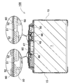
- FIG. 5 is an enlarged schematic cross-sectional view showing a gas duct portion of the power supply device according to the first embodiment. It is a cross-sectional view of the power supply device which shows the conventional outer edge prevention structure.
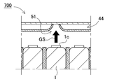
- FIG. 5 is a cross-sectional view showing a state in which gas is discharged in the power supply device of FIG.
- FIG. 6 is an exploded perspective view of FIG.
- FIG. 7 is an exploded perspective view of FIG. 7 viewed from diagonally below.
- FIG. 5 is a plan view of the power supply device of FIG. 1 in which the reinforcing cover is seen through.
- FIG. 5 is a cross-sectional view taken along the line XI-XI of FIG. 10 with an enlarged view of a main part.
- It is an enlarged schematic cross-sectional view which shows the gas duct part of the power supply device which does not provide the communication rib.
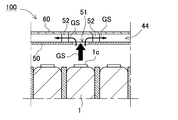
- It is an enlarged schematic cross-sectional view which shows the gas duct part of the power supply device which provided the communication rib.
- the embodiment of the present invention may be specified by the following configuration.
- the power supply device further includes an end plate that covers the side surface of the battery laminate, and the third cover is fixed to the end plate.
- the third cover can be firmly fixed to the power supply device by using the end plate, and the third cover can prevent the deformation of the second cover.
- the power supply device further comprises a pair of fastening members for fastening the end plates to each other on both side surfaces of the battery laminate.
- the battery laminate is provided with the pair of fastening members and a third cover on the upper surface to fasten the plurality of battery cells.
- a bus bar for connecting the electrode terminals of the battery cells constituting the battery laminate and a bus bar for connecting to the bus bar are further connected.
- the third cover forms an exposed portion for exposing the total terminal pieces.
- the third cover forms a bead.
- the strength can be improved by a simple process of forming a bead on the third cover.
- the first cover and the second cover are made of resin.
- the electric vehicle includes any of the above power supply devices, a traveling motor to which power is supplied from the power supply device, the power supply device, and the motor. It includes a main body and wheels driven by the motor to drive the vehicle main body.
- the power storage device includes any of the above power supply devices and a power supply controller that controls charging / discharging to the power supply device, and the power supply controller is used to generate electric power from the outside. Allows the battery cell to be charged and controls the battery cell to be charged.
- each element constituting the present invention may be configured such that a plurality of elements are composed of the same member and the plurality of elements are combined with one member, or conversely, the function of one member is performed by the plurality of members. It can also be shared and realized.
- the contents described in some examples and embodiments can be used in other embodiments and embodiments.
- the power supply device is a power source mounted on an electric vehicle such as a hybrid vehicle or an electric vehicle to supply electric power to a traveling motor, a power source for storing electric power generated by natural energy such as solar power generation or wind power generation, or a power source for storing electric power generated by natural energy such as solar power generation and wind power generation. It is used for various purposes such as a power source for storing midnight power, and is particularly suitable as a power source suitable for high power and large current applications.
- a power source for storing midnight power and is particularly suitable as a power source suitable for high power and large current applications.
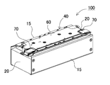
- FIGS. 1 and 2 show an exploded perspective view of the power supply device 100 according to the first embodiment of the present invention.
- FIG. 1 shows an exploded perspective view of the power supply device 100 according to the first embodiment
- FIG. 2 shows an exploded perspective view of the power supply device 100 shown in FIG.
- the power supply device 100 shown in these figures includes a battery laminate 10 in which a plurality of battery cells 1 are laminated, a pair of end plates 20 covering both end faces of the battery laminate 10, and a plurality of end plates 20 for fastening the end plates 20 to each other.
- a fastening member 15 and a cover assembly 40 provided on the upper surface of the battery laminate 10 are provided.
- the fastening member 15 is formed in a plate shape extending along the stacking direction of the plurality of battery cells 1.
- the fastening members 15 are arranged on opposite side surfaces of the battery laminate 10 to fasten the end plates 20 to each other. (Battery laminate 10)
- the battery laminate 10 is connected to a plurality of battery cells 1 having positive and negative electrode terminals 2 and electrode terminals 2 of the plurality of battery cells 1, and the plurality of battery cells 1 are arranged in parallel. It has a bus bar connected in series. A plurality of battery cells 1 are connected in parallel or in series via these bus bars.
- the battery cell 1 is a rechargeable secondary battery.
- a plurality of battery cells 1 are connected in parallel to form a parallel battery group, and a plurality of parallel battery groups are connected in series to connect a large number of battery cells 1 in parallel and in series.
- a plurality of battery cells 1 are laminated to form a battery laminate 10. Further, a pair of end plates 20 are arranged on both end faces of the battery laminate 10. The ends of the fastening members 15 are fixed to the end plates 20, and the stacked battery cells 1 are fixed in a pressed state. (Battery cell 1)
- the battery cell 1 is a square battery having a width wider than the thickness, in other words, a square battery thinner than the width, and is laminated in the thickness direction to form a battery laminate 10.
- the battery cell 1 can be, for example, a lithium ion secondary battery. Further, the battery cell can be any rechargeable secondary battery such as a nickel hydrogen battery or a nickel cadmium battery.
- positive and negative electrode plates are housed together with an electrolytic solution in an outer can 1a having a closed structure.
- the outer can 1a is formed by press-molding a metal plate such as aluminum or an aluminum alloy into a square shape, and the opening is hermetically sealed with a sealing plate 1b.
- the sealing plate 1b is made of the same aluminum or aluminum alloy as the square outer can 1a, and positive and negative electrode terminals 2 are fixed to both ends. Further, the sealing plate 1b is provided with a gas discharge valve 1c, which is a safety valve that opens according to a pressure change inside each of the battery cells 1, between the positive and negative electrode terminals 2.
- the plurality of battery cells 1 are laminated so that the thickness direction of each battery cell 1 is the stacking direction to form the battery laminate 10. At this time, the output of the battery laminate 10 can be increased by increasing the number of layers to be larger than usual. In such a case, the battery laminate 10 becomes a long one extended in the stacking direction.
- terminal surfaces 1X provided with positive and negative electrode terminals 2 are arranged on the same plane, and a plurality of battery cells 1 are laminated to form a battery laminate 10.
- the upper surface of the battery laminate 10 is a surface provided with gas discharge valves 1c of a plurality of battery cells 1. (Electrode terminal 2)
- the battery cell 1 has a sealing plate 1b, which is the top surface, as a terminal surface 1X, and positive and negative electrode terminals 2 are fixed to both ends of the terminal surface 1X.
- the electrode terminal 2 has a columnar protrusion.
- the protruding portion does not necessarily have to be cylindrical, and may be polygonal or elliptical.
- the positions of the positive and negative electrode terminals 2 fixed to the sealing plate 1b of the battery cell 1 are such that the positive electrode and the negative electrode are symmetrical.
- the battery cells 1 are flipped horizontally and stacked, and the electrode terminals 2 of the positive electrode and the negative electrode that are adjacent to each other are connected by a bus bar, so that the adjacent battery cells 1 are connected in series. I am trying to connect.
- the present invention does not specify the number of battery cells constituting the battery laminate and the connection state thereof.
- the number of battery cells constituting the battery laminate and the connection state thereof can be variously changed, including other embodiments described later.
- the plurality of battery cells 1 are laminated so that the thickness direction of each battery cell 1 is the stacking direction to form the battery laminate 10.
- a plurality of battery cells 1 are laminated so that the terminal surface 1X provided with the positive and negative electrode terminals 2 and the sealing plate 1b in FIG. 2 are flush with each other.
- the battery laminate 10 may have an insulating spacer 16 interposed between the battery cells 1 stacked adjacent to each other.
- the insulating spacer 16 is made of an insulating material such as resin in the form of a thin plate or sheet.
- the insulating spacer 16 has a plate shape having a size substantially equal to that of the facing surface of the battery cell 1.
- the insulating spacers 16 can be laminated between the battery cells 1 adjacent to each other to insulate the adjacent battery cells 1 from each other.
- a spacer having a shape in which a flow path of a cooling gas is formed between the battery cells and the spacer can also be used. Further, the surface of the battery cell can be covered with an insulating material.
- the surface of the outer can excluding the electrode terminal portion of the battery cell may be covered with a shrink film such as PET resin.
- the insulating spacer may be omitted.
- the battery cells connected in series with each other are insulated by interposing an insulating spacer between the battery cells connected in series with each other, while the battery cells connected in parallel with each other. Since there is no voltage difference between the adjacent outer cans, the insulating spacer between these battery cells can be omitted.
- end plates 20 are arranged on both end surfaces of the battery laminate 10.
- An end face spacer 17 may be interposed between the end plate 20 and the battery laminate 10 to insulate them.
- the end face spacer 17 can also be manufactured in the form of a thin plate or sheet with an insulating material such as resin.
- the bus bar holder may be arranged between the battery laminate 10 and the bus bar.
- a plurality of bus bars can be arranged at a fixed position on the upper surface of the battery laminate while insulating the plurality of bus bars from each other and insulating the terminal surface 1X of the battery cell from the bus bar.
- the cover assembly 40 described later may be integrated with the bus bar holder.
- the bus bar is manufactured into a predetermined shape by cutting and processing a metal plate.
- a metal plate constituting the bus bar a metal having low electric resistance and light weight, for example, an aluminum plate or a copper plate, or an alloy thereof can be used.
- other metals with low electrical resistance and light weight and alloys thereof can also be used.
- the end plates 20 are arranged at both ends of the battery laminate 10 and are fastened via a pair of left and right fastening members 15 arranged along both side surfaces of the battery laminate 10.
- the end plates 20 are both ends of the battery laminate 10 in the stacking direction of the battery cells 1, and are arranged outside the end face spacer 17 to sandwich the battery laminate 10 from both ends. (Fastening member 15)
- each fastening member 15 is made of metal having a predetermined width and a predetermined thickness along the side surface of the battery laminate 10, and is arranged so as to face both side surfaces of the battery laminate 10. There is.
- a metal plate such as iron, preferably a steel plate, can be used for the fastening member 15.
- the fastening member 15 made of a metal plate is bent by press molding or the like to form a predetermined shape.
- the fastening member 15 is formed by bending the upper and lower sides of the plate-shaped fastening main surface 15a in a U-shape to form a bent piece 15d.
- the upper and lower bent pieces 15d cover the upper and lower surfaces of the battery laminate 10 from the corners on the left and right side surfaces of the battery laminate 10.
- the fastening member 15 is fixed to the outer peripheral surface of the end plate 20 by screwing bolts 15f into a plurality of screw holes opened in the fastening main surface 15a.
- the fixing of the fastening main surface 15a and the end plate 20 is not necessarily limited to screwing using bolts, and may be a pin, a rivet, or the like.
- a plurality of battery cells 1 are connected by connecting end plates 20 arranged at both ends of a battery laminate 10 composed of the plurality of battery cells 1 with fastening members 15. Is configured to constrain. By restraining the plurality of battery cells 1 via the end plate 20 and the fastening member 15 having high rigidity, it is possible to suppress expansion, deformation, relative movement, malfunction due to vibration, etc. of the battery cells 1 due to charge / discharge and deterioration. .. (Insulation sheet 30)
- an insulating sheet 30 is interposed between the fastening member 15 and the battery laminate 10.
- the insulating sheet 30 is made of an insulating material such as resin, and insulates between the metal fastening member 15 and the battery cell.
- the insulating sheet 30 shown in FIG. 2 and the like is composed of a flat plate 31 that covers the side surface of the battery laminate 10 and bent covering portions 32 provided above and below the flat plate 31.
- the bent covering portion 32 is bent in a U shape from the flat plate 31 so as to cover the bent piece 15d of the fastening member 15, and then further folded back.
- the bent piece 15d can be covered with an insulating bent covering portion from the upper surface to the side surface and the lower surface, thereby avoiding unintended conduction between the battery cell 1 and the fastening member 15.
- each battery cell 1 presses the upper surface and the lower surface of the battery cell 1 of the battery laminate 10 via the bent covering portion 32.
- each battery cell 1 is pressed from the vertical direction by the bent piece 15d and held in the height direction, and even if vibration, impact, or the like is applied to the battery laminate 10, each battery cell 1 is positioned in the vertical direction. It can be maintained so that it does not shift.
- the battery cell When the surface of the battery laminate or the battery laminate is insulated, for example, the battery cell is housed in an insulating case, covered with a heat-shrinkable resin film, or the fastening member. If the surface is coated with an insulating paint or coating, or if the fastening member is made of an insulating material, the insulating sheet can be unnecessary. Further, the insulating sheet 30 may also have the bent covering portion 32 formed only on the upper end side when it is not necessary to consider the insulation of the fastening member 15 with the bent piece 15d on the lower surface side of the battery laminate 10. For example, the case where the battery cell 1 is covered with a heat-shrinkable film is applicable. Further, the insulating sheet 30 may be configured to also serve as a bus bar holder for holding the bus bar described above. (Cover assembly 40)
- the power supply device 100 is provided with a cover assembly 40 on the upper surface of the battery laminate 10.
- the cover assembly 40 constitutes a gas discharge path for discharging the high-temperature and high-pressure gas to the outside of the power supply device 100 when the high-temperature and high-pressure gas is discharged from any of the battery cells 1 constituting the battery stack 10.
- the cover assembly 40 may be configured to also serve as a bus bar holder for holding the bus bar.
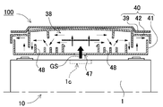
- the cover assembly 40 includes a first cover 41, a second cover 42, and a third cover 39, as shown in the schematic cross-sectional view of FIG.
- the first cover 41 is provided on the upper surface of the battery laminate 10.
- the first cover 41 has a gas introduction port 47 opened at a position corresponding to the gas discharge valve 1c of the battery cell 1 constituting the battery laminate 10.
- the second cover 42 is provided on the upper surface of the first cover 41, and forms a gas duct 38 with the first cover 41.
- a baffle plate 48 is formed between the first cover 41 and the second cover 42.
- the third cover 39 is provided on the upper surface of the second cover 42, and is in contact with the upper surface of the second cover 42.
- the third cover 39 is made of metal.
- a large number of baffle plates 48 are provided in the gas duct 38, and the gas GS is bent so as to be discharged along the baffle plate 48. It is possible to reduce the momentum and also reduce the temperature so that it can be safely discharged to the outside.
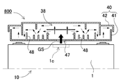
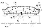
- the gas duct 38 is deformed by the gas pressure, and as a result, a gas discharge path avoiding the obstruction plate 48 is formed. It is conceivable that the gas GS is discharged to the outside of the power supply device at a high pressure and temperature.
- the first cover 41 and the second cover 42 constituting the gas duct 38 are made of resin from the viewpoint of insulation and the like, there is a limit to the resistance to deformation.
- deformation due to gas pressure can be suppressed by covering the upper surface of the second cover 42 with a metal third cover 39 as shown in FIG. can.
- the rigidity against the expansion of the battery cell can be improved by the third cover 39. Since the battery cell 1 expands due to charging and discharging, such deformations are accumulated and the total length of the battery laminate 10 also changes. As shown in FIG. 2, the end plate 20 is arranged on the end surface of the battery laminate 10 so as to counter the swelling force of the battery laminate 10, and the end plate 20 is arranged on the side surface of the battery laminate 10 with the fastening member 15. We have concluded each other. By fixing the third cover 39 to the end plate 20, it is possible to improve the rigidity of the battery cell against the swelling force even on the upper surface of the battery laminate 10.
- the first cover 41 and the second cover 42 are made of resin that ensures insulation and easily forms a baffle plate 48 inside the gas duct 38, and assigns different functions to each cover and assigns them to each cover. It is made of materials according to the functions provided.
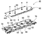
- FIG. 6 is an exploded perspective view showing a state in which the reinforcing cover 60 is removed from the cover assembly 40 of FIG. 2
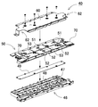
- FIG. 7 is an exploded perspective view of FIG. 6,
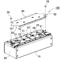
- FIG. 9 is an exploded perspective view showing a state in which the reinforcing cover 60 is removed from the power supply device 100 of FIG. 1
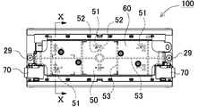
- FIG. 10 is a plan view of the power supply device 100 of FIG. 10 shows a cross-sectional view with an enlarged view of a main part on the XI-XI line of FIG.
- the cover assembly 40 shown in these figures includes a lower cover 46, an upper cover 50, and a reinforcing cover 60.
- the lower cover corresponds to the first cover 41 described above
- the upper cover 50 corresponds to the second cover 42
- the reinforcing cover 60 corresponds to the third cover 39. (Bottom cover 46)
- the lower cover 46 is provided on the upper surface of the battery laminate 10 and defines a first gas duct that communicates with the gas discharge valve 1c. As shown in FIGS. 7 to 8, the lower cover 46 has a gas introduction port 47 opened at a position corresponding to the gas discharge valve 1c of the battery cell 1. Further, as shown in FIGS. 7 to 8, 11 and the like, the lower cover 46 forms a large number of baffle plates 48, and the baffle plate 48 rotates in the traveling direction until the high temperature and high pressure gas is discharged. By being modified, the momentum is reduced and the temperature is lowered. Further, the gas discharge path is provided not only in the stacking direction of the battery cells 1 but also in the direction intersecting the stacking direction.
- the lower cover 46 is made of a resin having excellent insulating properties, for example, polycarbonate. (Intermediate plate 49)
- An intermediate plate 49 is provided on the upper surface of the lower cover 46.
- the intermediate plate 49 is provided in the center of the battery laminate 10 in the width direction, and is arranged so as to face the gas discharge valve 1c.
- the intermediate plate 49 is made of a material having excellent strength, for example, metal.
- the upper cover 50 is provided on the upper surface of the lower cover 46, and defines the second gas duct on the upper surface of the first gas duct.
- the upper cover 50 is made of resin.
- a plurality of communication holes 51 for communicating the first gas duct and the second gas duct are formed on the upper surface of the upper cover 50.
- the communication holes 51 are not opened corresponding to all the battery cells, but are opened discretely so as to take charge of a plurality of battery cells. In the example of FIG. 7, etc., the communication holes 51 are opened at three locations in the stacking direction with respect to the battery laminate 10 in which the battery cells 1 of 12 cells are laminated.
- the communication hole 51 is provided at an offset position, not at a position facing the gas discharge valve 1c. By not opening the communication hole 51 directly with respect to the gas discharge valve 1c, it is possible to facilitate the dispersion of gas.
- the gas discharge valve 1c is provided in the center of the sealing plate 1b of the battery cell 1 in the example shown in FIG.
- the communication holes 51 are opened at positions corresponding to the left and right of the sealing plate 1b of the battery cell 1.
- the communication hole 51 is preferably formed in a slit shape.
- the width and length of the slit, the height of the second gas duct, and the like can be adjusted to set the path area of the second gas duct, and the amount of gas discharged can be controlled.
- the height of the second gas duct is defined by the height of the communication rib 52 described later. (Communication rib 52)
- the upper cover 50 is provided with a communication rib 52 protruding toward the reinforcing cover 60 around the communication hole 51. By doing so, it is possible to prevent a situation in which the path for introducing gas into the second gas duct is obstructed.
- the communication rib is not provided, when the high-pressure gas is discharged from the gas discharge valve 1c as in the power supply device 700 shown in the schematic cross-sectional view of FIG. 12, the upper cover 50 is opened by the pressure of the gas. It is conceivable that the periphery of the communication hole 51 is deformed to block the gas discharge path. In this state, the gas is not guided to the second gas duct, and the gas cannot be dispersed and discharged through the second gas duct.
- the communication rib 52 is provided not all around the communication hole 51 but a part thereof so as not to obstruct the inflow of gas into the second gas duct.
- a pair of communication ribs 52 are provided so as to face both sides of the communication hole 51.
- the communication rib 52 is integrally formed with the resin upper cover 50. With this configuration, the communication rib 52 can be easily formed by positioning the communication rib 52 around the communication hole 51.
- a communication rib may be provided on the reinforcing cover side.
- a communication rib may be provided on the reinforcing cover side.
- the upper cover 50 is provided with a partition rib 53 for partitioning between adjacent communication holes 51.
- the second gas duct can be partitioned for each communication hole 51, and the high-pressure gas introduced into the second gas duct from the communication hole 51 can be prevented from being concentrated and discharged in one place.
- the battery laminate 10 in which the battery cells 1 of 12 cells are laminated is divided into three sections every four cells, and the battery cell 1 is further divided into two parts on the left and right sides, for a total of six sections. It is divided.
- the partition ribs are projected on the upper surface of the upper cover 50, but the present invention is not limited to this configuration, and it goes without saying that the partition ribs may be projected from the reinforcing cover side, for example. ..
- the gas discharge path is provided not only in the stacking direction of the battery cells 1 but also in the direction intersecting the stacking direction. By discharging the gas from the intersecting directions in this way, it is possible to efficiently discharge the gas to the outside of the power supply device and enhance the safety.
- gas discharge paths are formed in the first gas duct and the second gas duct, respectively, so that the gas is also discharged in the vertical direction in the figure. (Reinforcing cover 60)
- the reinforcing cover 60 is provided on the upper surface of the upper cover 50.
- a second gas duct is formed between the reinforcing cover 60 and the upper cover 50. Further, the reinforcing cover 60 is in contact with the upper surface of the upper cover 50 via the communication rib 52.
- the reinforcing cover 60 is fixed to the upper surface of the end plate 20 with bolts 29 or the like as shown in FIG.
- the upper surface of the battery laminate 10 is also fastened with the reinforcing cover 60, and the end surface of the battery laminate 10 is pressed by the end plate 20.
- the rigidity to be increased can be increased.
- the reinforcing cover 60 is also used as an additional fastening member.
- the reinforcing cover 60 may form a bead 61 in order to increase the rigidity.
- a bead 61 is formed in the center along the longitudinal direction of the reinforcing cover 60. In this way, the strength can be improved by a simple process of forming the bead 61 on the reinforcing cover 60 of the metal plate. (Total terminal piece 70)
- the power supply device includes a total terminal piece 70 that takes out the total output by connecting a plurality of battery cells 1 in series and in parallel via a bus bar.
- the total terminal piece 70 is made of a metal plate having excellent conductivity.
- the reinforcing cover 60 forms an exposed portion 62 that exposes the total terminal piece 70.
- the exposed portion 62 can be an exposed cutout in which a corner portion of the reinforcing cover 60 is cut out so as to expose the total terminal piece 70.
- the metal reinforcing cover 60 and the total terminal piece 70 are separated from each other in the horizontal plane so as not to overlap each other, and the safety is enhanced.
- the display unit 62 may be a bay window for displaying all the terminal pieces.
- the total terminal piece 70 is provided on one side surface side (lower side in the figure) of the upper surface of the end plate 20.
- the exposed portion 62 is formed only in the lower corner portion of the end portion of the reinforcing cover 60, and may be provided on both sides of the end portion as shown in FIG. 9 or the like.
- the above power supply device 100 can be used as a power source for a vehicle that supplies electric power to a motor that runs an electric vehicle.
- an electric vehicle such as a hybrid vehicle or a plug-in hybrid vehicle that runs on both an engine and a motor, or an electric vehicle that runs only on a motor can be used, and is used as a power source for these vehicles. Will be done.
- a large number of the above-mentioned power supply devices 100 are connected in series or in parallel, and a large-capacity, high-output power supply device to which a necessary control circuit is added is constructed. do. (Power supply for hybrid vehicles)
- FIG. 15 shows an example in which the power supply device 100 is mounted on a hybrid vehicle traveling by both an engine and a motor.
- the vehicle HV equipped with the power supply device 100 shown in this figure is driven by a vehicle main body 91, an engine 96 for running the vehicle main body 91, a running motor 93, and these engines 96 and a running motor 93. It includes wheels 97, a power supply device 100 that supplies electric power to the motor 93, and a generator 94 that charges the batteries of the power supply device 100.
- the power supply device 100 is connected to the motor 93 and the generator 94 via the DC / AC inverter 95.
- the vehicle HV runs on both the motor 93 and the engine 96 while charging and discharging the battery of the power supply device 100.
- the motor 93 is driven to drive the vehicle in a region where the engine efficiency is low, for example, when accelerating or traveling at a low speed.
- the motor 93 is driven by being supplied with electric power from the power supply device 100.
- the generator 94 is driven by the engine 96 or by regenerative braking when braking the vehicle to charge the battery of the power supply device 100.
- the vehicle HV may be provided with a charging plug 98 for charging the power supply device 100. By connecting the charging plug 98 to an external power source, the power supply device 100 can be charged. (Power supply for electric vehicles)
- FIG. 16 shows an example in which the power supply device 100 is mounted on an electric vehicle traveling only by a motor.
- the vehicle EV equipped with the power supply device 100 shown in this figure supplies electric power to the vehicle main body 91, the traveling motor 93 for running the vehicle main body 91, the wheels 97 driven by the motor 93, and the motor 93.
- It includes a power supply device 100 for supplying power and a generator 94 for charging the battery of the power supply device 100.
- the power supply device 100 is connected to the motor 93 and the generator 94 via the DC / AC inverter 95.
- the motor 93 is driven by being supplied with electric power from the power supply device 100.
- the generator 94 is driven by the energy used for regenerative braking of the vehicle EV to charge the battery of the power supply device 100. Further, the vehicle EV is provided with a charging plug 98, and the charging plug 98 can be connected to an external power source to charge the power supply device 100. (Power supply device for power storage device)
- the present invention does not specify the use of the power supply device as the power supply of the motor that runs the vehicle.
- the power supply device according to the embodiment can also be used as a power source for a power storage device that charges and stores a battery with electric power generated by solar power generation, wind power generation, or the like.
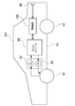
- FIG. 17 shows a power storage device in which the battery of the power supply device 100 is charged by the solar cell 82 to store electricity.
- the power storage device shown in FIG. 17 charges the battery of the power supply device 100 with the electric power generated by the solar cells 82 arranged on the roof or roof of a building 81 such as a house or factory.
- This power storage device uses the solar cell 82 as a power source for charging, charges the battery of the power supply device 100 with the charging circuit 83, and then supplies power to the load 86 via the DC / AC inverter 85. Therefore, this power storage device has a charge mode and a discharge mode.
- the DC / AC inverter 85 and the charging circuit 83 are connected to the power supply device 100 via the discharge switch 87 and the charging switch 84, respectively.
- the ON / OFF of the discharge switch 87 and the charge switch 84 is switched by the power controller 88 of the power storage device.
- the power controller 88 switches the charging switch 84 to ON and the discharge switch 87 to OFF to allow the charging circuit 83 to charge the power supply device 100.
- the power controller 88 turns off the charging switch 84 and turns on the discharge switch 87 to switch to the discharge mode, and the power supply device 100 Allows discharge from to load 86.
- the charge switch 84 can be turned on and the discharge switch 87 can be turned on to supply power to the load 86 and charge the power supply device 100 at the same time.
- the power supply device can also be used as a power source for a power storage device that charges and stores batteries using midnight power at night.
- a power supply device charged with midnight power can be charged with midnight power, which is surplus power of a power plant, and output power in the daytime when the power load is large, so that the peak power in the daytime can be limited to a small value.
- the power supply can also be used as a power source for charging with both solar cell output and midnight power. This power supply device can effectively utilize both the power generated by the solar cell and the midnight power, and can efficiently store electricity while considering the weather and power consumption.
- the above-mentioned power storage system includes a backup power supply device that can be mounted in a computer server rack, a backup power supply device for a wireless base station such as a mobile phone, a power storage power supply for home or factory use, a power supply for street lights, and the like. It can be suitably used for power storage devices combined with solar cells, backup power sources for traffic lights and road traffic indicators, and the like.
- the power supply device is used as a power source for a large current used as a power source for a motor for driving an electric vehicle such as a hybrid vehicle, a fuel cell vehicle, an electric vehicle, or an electric motorcycle. It can be preferably used.
- a power supply device for a plug-in type hybrid electric vehicle, a hybrid type electric vehicle, an electric vehicle, or the like that can switch between an EV driving mode and a HEV driving mode can be mentioned.
- a backup power supply that can be mounted in a computer server rack, a backup power supply for wireless base stations such as mobile phones, a power storage device for home use and factories, a power supply for street lights, etc. , Can also be used as appropriate for backup power supplies such as traffic lights.
Landscapes
- Chemical & Material Sciences (AREA)
- Chemical Kinetics & Catalysis (AREA)
- Electrochemistry (AREA)
- General Chemical & Material Sciences (AREA)
- Engineering & Computer Science (AREA)
- Inorganic Chemistry (AREA)
- Manufacturing & Machinery (AREA)
- Aviation & Aerospace Engineering (AREA)
- Battery Mounting, Suspending (AREA)
Abstract
Description
[実施形態1]
(電池積層体10)
(電池セル1)
(電極端子2)
(エンドプレート20)
(締結部材15)
(絶縁シート30)
(カバー集合体40)
(下カバー46)
(中間プレート49)
(上カバー50)
(連通孔51)
(連通用リブ52)
(区画用リブ53)
(補強カバー60)
(総端子片70)
(ハイブリッド車用電源装置)
(電気自動車用電源装置)
(蓄電装置用の電源装置)
1…電池セル
1X…端子面
1a…外装缶
1b…封口板
1c…ガス排出弁
2…電極端子
10…電池積層体
15…締結部材;15a…締結主面;15d…折曲片
15f…ボルト
16…絶縁スペーサ
17…端面スペーサ
20…エンドプレート
29…ボルト
30…絶縁シート;31…平板;32…折曲被覆部
38…ガスダクト
39…第三カバー
40…カバー集合体
41…第一カバー
42…第二カバー
46…下カバー
47…ガス導入口
48…邪魔板
49…中間プレート
50…上カバー
51…連通孔
52…連通用リブ
53…区画用リブ
60…補強カバー
61…ビード
62…表出部
70…総端子片
81…建物
82…太陽電池
83…充電回路
84…充電スイッチ
85…DC/ACインバータ
86…負荷
87…放電スイッチ
88…電源コントローラ
91…車両本体
93…モータ
94…発電機
95…DC/ACインバータ
96…エンジン
97…車輪
98…充電プラグ
GS…ガス
HV、EV…車両
Claims (8)
- 外装缶の内圧上昇時に開弁するガス排出弁、及び電極を上面に形成した電池セルを、複数積層した電池積層体と、
前記電池積層体の上面に設けられ、前記ガス排出弁と対応する位置をそれぞれ開口させた第一カバーと、
前記第一カバーの上面に設けられ、該第一カバーとの間でガスダクトを画成する第二カバーと、
を備える電源装置であって、
前記ガスダクトは、前記第一カバーと第二カバーとの間に邪魔板を形成しており、
前記電源装置はさらに、
前記第二カバーの上面に設けられ、該第二カバーの上面を当接する金属製の第三カバーを備えてなる電源装置。 - 請求項1に記載の電源装置であって、さらに、
前記電池積層体の側面を覆うエンドプレートを備えており、
前記第三カバーが、前記エンドプレートに固定されてなる電源装置。 - 請求項2に記載の電源装置であって、さらに、
前記電池積層体は、前記エンドプレート同士を前記電池積層体の両側側面で締結する一対の締結部材を備えており、
前記電池積層体は、前記一対の締結部材と、上面の第三カバーでもって前記複数の電池セルを締結してなる電源装置。 - 請求項1~3のいずれか一項に記載の電源装置であって、さらに、
前記電池積層体を構成する前記電池セルの電極同士を接続するバスバーと、
前記バスバーと接続された総端子片と
を備えており、
前記第三カバーは、前記総端子片を表出させる表出部を形成してなる電源装置。 - 請求項1~4のいずれか一項に記載の電源装置であって、
前記第三カバーは、ビードを形成してなる電源装置。 - 請求項1~5のいずれか一項に記載の電源装置であって、
前記第一カバー及び第二カバーが、樹脂製である電源装置。 - 請求項1~6のいずれか一に記載の電源装置を備える車両であって、
前記電源装置と、該電源装置から電力供給される走行用のモータと、前記電源装置及び前記モータを搭載してなる車両本体と、前記モータで駆動されて前記車両本体を走行させる車輪とを備える車両。 - 請求項1~6のいずれか一に記載の電源装置を備える蓄電装置であって、
前記電源装置と、該電源装置への充放電を制御する電源コントローラとを備えており、
前記電源コントローラでもって、外部からの電力により前記電池セルへの充電を可能とすると共に、該電池セルに対し充電を行うよう制御する蓄電装置。
Priority Applications (4)
| Application Number | Priority Date | Filing Date | Title |
|---|---|---|---|
| JP2022511563A JP7680428B2 (ja) | 2020-03-31 | 2021-01-20 | 電源装置及びこれを備える車両並びに蓄電装置 |
| EP21780643.9A EP4131612B1 (en) | 2020-03-31 | 2021-01-20 | Power supply device, and vehicle and electrical storage device each equipped with same |
| US17/906,879 US20230178844A1 (en) | 2020-03-31 | 2021-01-20 | Power supply device, and vehicle and electrical storage device each equipped with same |
| CN202180011287.6A CN115004471A (zh) | 2020-03-31 | 2021-01-20 | 电源装置、具备该电源装置的车辆以及蓄电装置 |
Applications Claiming Priority (2)
| Application Number | Priority Date | Filing Date | Title |
|---|---|---|---|
| JP2020-064066 | 2020-03-31 | ||
| JP2020064066 | 2020-03-31 |
Publications (1)
| Publication Number | Publication Date |
|---|---|
| WO2021199595A1 true WO2021199595A1 (ja) | 2021-10-07 |
Family
ID=77929816
Family Applications (1)
| Application Number | Title | Priority Date | Filing Date |
|---|---|---|---|
| PCT/JP2021/001787 Ceased WO2021199595A1 (ja) | 2020-03-31 | 2021-01-20 | 電源装置及びこれを備える車両並びに蓄電装置 |
Country Status (5)
| Country | Link |
|---|---|
| US (1) | US20230178844A1 (ja) |
| EP (1) | EP4131612B1 (ja) |
| JP (1) | JP7680428B2 (ja) |
| CN (1) | CN115004471A (ja) |
| WO (1) | WO2021199595A1 (ja) |
Cited By (8)
| Publication number | Priority date | Publication date | Assignee | Title |
|---|---|---|---|---|
| JP2023067618A (ja) * | 2021-11-01 | 2023-05-16 | 株式会社Gsユアサ | 蓄電装置 |
| JP2023545562A (ja) * | 2021-08-06 | 2023-10-30 | 寧徳時代新能源科技股▲分▼有限公司 | 電池の筐体、電池、電力消費装置、電池を製造する方法と装置 |
| JP2024507463A (ja) * | 2021-07-07 | 2024-02-20 | エルジー エナジー ソリューション リミテッド | クーリングフィンが合致されたパックケースを備えたバッテリーパック |
| JP2025519162A (ja) * | 2023-04-28 | 2025-06-24 | エルジー エナジー ソリューション リミテッド | バッテリーパック及びそれを含む自動車 |
| JP2026005208A (ja) * | 2024-06-26 | 2026-01-15 | 嘉盈▲リー▼源股▲フン▼有限公司 | 電池モジュール及びその電池用ケース |
| JP2026502587A (ja) * | 2023-09-07 | 2026-01-23 | エルジー エナジー ソリューション リミテッド | バッテリーパック及びこれを含むエネルギー貯蔵システム(ess) |
| JP2026514322A (ja) * | 2024-02-27 | 2026-05-11 | エルジー エナジー ソリューション リミテッド | バッテリーパック及びそれを含む自動車 |
| JP2026519732A (ja) * | 2024-05-08 | 2026-06-18 | エルジー エナジー ソリューション リミテッド | バッテリーパック |
Families Citing this family (5)
| Publication number | Priority date | Publication date | Assignee | Title |
|---|---|---|---|---|
| CN118589141A (zh) * | 2019-02-15 | 2024-09-03 | 松下新能源株式会社 | 电源装置 |
| DE102021109302B3 (de) * | 2021-04-14 | 2022-07-28 | Dr. Ing. H.C. F. Porsche Aktiengesellschaft | Batterievorrichtung |
| JP7768198B2 (ja) * | 2023-06-27 | 2025-11-12 | トヨタ自動車株式会社 | 電池パック |
| DE102023210235A1 (de) * | 2023-10-18 | 2025-04-24 | Volkswagen Aktiengesellschaft | Zellanordnung sowie eine Batterie mit einer solchen Zellanordnung |
| CN119864603B (zh) * | 2025-01-13 | 2025-10-17 | 孝感楚能新能源创新科技有限公司 | 一种电池汇流结构集成方法及电池包 |
Citations (4)
| Publication number | Priority date | Publication date | Assignee | Title |
|---|---|---|---|---|
| JP2011100699A (ja) * | 2009-11-09 | 2011-05-19 | Sanyo Electric Co Ltd | 車両用電源装置及びこれを備える車両並びに車両用電源装置の製造方法 |
| JP2013218790A (ja) * | 2012-04-04 | 2013-10-24 | Tigers Polymer Corp | ガス排出管 |
| JP2015133169A (ja) * | 2012-04-27 | 2015-07-23 | 三洋電機株式会社 | 電源装置及びこれを備える車両並びに蓄電装置 |
| JP2015138673A (ja) * | 2014-01-22 | 2015-07-30 | 株式会社豊田自動織機 | 電池モジュール |
Family Cites Families (14)
| Publication number | Priority date | Publication date | Assignee | Title |
|---|---|---|---|---|
| JP5466906B2 (ja) * | 2009-09-18 | 2014-04-09 | パナソニック株式会社 | 電池モジュール |
| JP2011204574A (ja) * | 2010-03-26 | 2011-10-13 | Panasonic Corp | 電池パック |
| JP2013214354A (ja) * | 2010-07-30 | 2013-10-17 | Panasonic Corp | 電池モジュール |
| JP2012212558A (ja) * | 2011-03-31 | 2012-11-01 | Panasonic Corp | 電池モジュール |
| WO2013031612A1 (ja) * | 2011-08-26 | 2013-03-07 | 三洋電機株式会社 | 電源装置及びこれを備える車両並びに蓄電装置 |
| WO2014024434A1 (ja) * | 2012-08-09 | 2014-02-13 | 三洋電機株式会社 | 電源装置及びこれを備える電動車両並びに蓄電装置 |
| JP6151254B2 (ja) * | 2012-08-09 | 2017-06-21 | 三洋電機株式会社 | 電源装置及びこれを備える電動車両並びに蓄電装置 |
| JP5709908B2 (ja) * | 2013-01-11 | 2015-04-30 | 三菱重工業株式会社 | 組電池カバー、電池モジュール、及び電池システム |
| JP2016035817A (ja) * | 2014-08-01 | 2016-03-17 | 三菱重工業株式会社 | モジュールカバー上部構造体、電池モジュール及び電池モジュールの熱暴走防止方法 |
| JP6574987B2 (ja) * | 2015-02-25 | 2019-09-18 | パナソニックIpマネジメント株式会社 | 電池モジュール |
| JP2017010777A (ja) * | 2015-06-22 | 2017-01-12 | カルソニックカンセイ株式会社 | 組電池及び電源装置 |
| JP6821391B2 (ja) * | 2016-10-26 | 2021-01-27 | 三洋電機株式会社 | 電源装置及びこれを用いる車両並びに蓄電装置 |
| CN207765491U (zh) * | 2017-11-29 | 2018-08-24 | 长城汽车股份有限公司 | 电池包和具有其的车辆 |
| JP7023367B2 (ja) * | 2018-08-22 | 2022-02-21 | ビークルエナジージャパン株式会社 | 電池パック |
-
2021
- 2021-01-20 EP EP21780643.9A patent/EP4131612B1/en active Active
- 2021-01-20 US US17/906,879 patent/US20230178844A1/en active Pending
- 2021-01-20 WO PCT/JP2021/001787 patent/WO2021199595A1/ja not_active Ceased
- 2021-01-20 CN CN202180011287.6A patent/CN115004471A/zh active Pending
- 2021-01-20 JP JP2022511563A patent/JP7680428B2/ja active Active
Patent Citations (4)
| Publication number | Priority date | Publication date | Assignee | Title |
|---|---|---|---|---|
| JP2011100699A (ja) * | 2009-11-09 | 2011-05-19 | Sanyo Electric Co Ltd | 車両用電源装置及びこれを備える車両並びに車両用電源装置の製造方法 |
| JP2013218790A (ja) * | 2012-04-04 | 2013-10-24 | Tigers Polymer Corp | ガス排出管 |
| JP2015133169A (ja) * | 2012-04-27 | 2015-07-23 | 三洋電機株式会社 | 電源装置及びこれを備える車両並びに蓄電装置 |
| JP2015138673A (ja) * | 2014-01-22 | 2015-07-30 | 株式会社豊田自動織機 | 電池モジュール |
Non-Patent Citations (1)
| Title |
|---|
| See also references of EP4131612A4 * |
Cited By (12)
| Publication number | Priority date | Publication date | Assignee | Title |
|---|---|---|---|---|
| JP2024507463A (ja) * | 2021-07-07 | 2024-02-20 | エルジー エナジー ソリューション リミテッド | クーリングフィンが合致されたパックケースを備えたバッテリーパック |
| JP7712369B2 (ja) | 2021-07-07 | 2025-07-23 | エルジー エナジー ソリューション リミテッド | クーリングフィンが合致されたパックケースを備えたバッテリーパック |
| JP2023545562A (ja) * | 2021-08-06 | 2023-10-30 | 寧徳時代新能源科技股▲分▼有限公司 | 電池の筐体、電池、電力消費装置、電池を製造する方法と装置 |
| JP7596527B2 (ja) | 2021-08-06 | 2024-12-09 | 香港時代新能源科技有限公司 | 電池の筐体、電池、電力消費装置、電池を製造する方法と装置 |
| JP2023067618A (ja) * | 2021-11-01 | 2023-05-16 | 株式会社Gsユアサ | 蓄電装置 |
| JP7834986B2 (ja) | 2021-11-01 | 2026-03-25 | 株式会社Gsユアサ | 蓄電装置 |
| JP2025519162A (ja) * | 2023-04-28 | 2025-06-24 | エルジー エナジー ソリューション リミテッド | バッテリーパック及びそれを含む自動車 |
| JP2026502587A (ja) * | 2023-09-07 | 2026-01-23 | エルジー エナジー ソリューション リミテッド | バッテリーパック及びこれを含むエネルギー貯蔵システム(ess) |
| JP2026514322A (ja) * | 2024-02-27 | 2026-05-11 | エルジー エナジー ソリューション リミテッド | バッテリーパック及びそれを含む自動車 |
| JP7900613B2 (ja) | 2024-02-27 | 2026-08-04 | エルジー エナジー ソリューション リミテッド | バッテリーパック及びそれを含む自動車 |
| JP2026519732A (ja) * | 2024-05-08 | 2026-06-18 | エルジー エナジー ソリューション リミテッド | バッテリーパック |
| JP2026005208A (ja) * | 2024-06-26 | 2026-01-15 | 嘉盈▲リー▼源股▲フン▼有限公司 | 電池モジュール及びその電池用ケース |
Also Published As
| Publication number | Publication date |
|---|---|
| EP4131612B1 (en) | 2024-12-04 |
| CN115004471A (zh) | 2022-09-02 |
| EP4131612A1 (en) | 2023-02-08 |
| JP7680428B2 (ja) | 2025-05-20 |
| EP4131612A4 (en) | 2023-10-04 |
| US20230178844A1 (en) | 2023-06-08 |
| JPWO2021199595A1 (ja) | 2021-10-07 |
Similar Documents
| Publication | Publication Date | Title |
|---|---|---|
| JP7680428B2 (ja) | 電源装置及びこれを備える車両並びに蓄電装置 | |
| WO2021199594A1 (ja) | 電源装置及びこれを備える車両並びに蓄電装置 | |
| JP7649294B2 (ja) | 電源装置及びこれを備える車両並びに蓄電装置 | |
| EP3855526B1 (en) | Power supply device, vehicle having power supply device, and power storage device | |
| CN115053386B (zh) | 电源装置和具备该电源装置的车辆以及蓄电装置 | |
| US12531306B2 (en) | Power supply device, electric vehicle using same, and power storage device | |
| WO2020194937A1 (ja) | 電源装置及びこれを用いた電動車両並びに蓄電装置 | |
| JP7348174B2 (ja) | 電池モジュール及びこれを備える車両 | |
| JPWO2019187314A1 (ja) | 電源装置及びこれを備える車両 | |
| WO2021024772A1 (ja) | 電源装置及びこれを用いた電動車両並びに蓄電装置 | |
| CN113632300B (zh) | 电源装置和使用该电源装置的电动车辆以及蓄电装置 | |
| CN113646956B (zh) | 电源装置和使用该电源装置的电动车辆以及蓄电装置、电源装置用紧固构件、电源装置的制造方法、电源装置用紧固构件的制造方法 | |
| US12500302B2 (en) | Power source device, and vehicle and power storage device each equipped with same | |
| JP2021163629A (ja) | 電源装置及びこれを備える車両並びに蓄電装置 | |
| WO2021199535A1 (ja) | 電源装置及びこれを備える車両並びに蓄電装置 | |
| WO2021157139A1 (ja) | 電源装置及びこれを用いた電動車両並びに蓄電装置 |
Legal Events
| Date | Code | Title | Description |
|---|---|---|---|
| 121 | Ep: the epo has been informed by wipo that ep was designated in this application |
Ref document number: 21780643 Country of ref document: EP Kind code of ref document: A1 |
|
| ENP | Entry into the national phase |
Ref document number: 2022511563 Country of ref document: JP Kind code of ref document: A |
|
| WWE | Wipo information: entry into national phase |
Ref document number: 202247061516 Country of ref document: IN |
|
| NENP | Non-entry into the national phase |
Ref country code: DE |
|
| ENP | Entry into the national phase |
Ref document number: 2021780643 Country of ref document: EP Effective date: 20221031 |