WO2021199620A1 - Procédé de production d'halogénures - Google Patents
Procédé de production d'halogénures Download PDFInfo
- Publication number
- WO2021199620A1 WO2021199620A1 PCT/JP2021/002516 JP2021002516W WO2021199620A1 WO 2021199620 A1 WO2021199620 A1 WO 2021199620A1 JP 2021002516 W JP2021002516 W JP 2021002516W WO 2021199620 A1 WO2021199620 A1 WO 2021199620A1
- Authority
- WO
- WIPO (PCT)
- Prior art keywords
- firing
- containing compound
- halide
- solid electrolyte
- firing step
- Prior art date
- Legal status (The legal status is an assumption and is not a legal conclusion. Google has not performed a legal analysis and makes no representation as to the accuracy of the status listed.)
- Ceased
Links
Images


Classifications
-
- H—ELECTRICITY
- H01—ELECTRIC ELEMENTS
- H01B—CABLES; CONDUCTORS; INSULATORS; SELECTION OF MATERIALS FOR THEIR CONDUCTIVE, INSULATING OR DIELECTRIC PROPERTIES
- H01B1/00—Conductors or conductive bodies characterised by the conductive materials; Selection of materials as conductors
- H01B1/06—Conductors or conductive bodies characterised by the conductive materials; Selection of materials as conductors mainly consisting of other non-metallic substances
- H01B1/08—Conductors or conductive bodies characterised by the conductive materials; Selection of materials as conductors mainly consisting of other non-metallic substances oxides
-
- C—CHEMISTRY; METALLURGY
- C01—INORGANIC CHEMISTRY
- C01F—COMPOUNDS OF THE METALS BERYLLIUM, MAGNESIUM, ALUMINIUM, CALCIUM, STRONTIUM, BARIUM, RADIUM, THORIUM, OR OF THE RARE-EARTH METALS
- C01F17/00—Compounds of rare earth metals
- C01F17/30—Compounds containing rare earth metals and at least one element other than a rare earth metal, oxygen or hydrogen, e.g. La4S3Br6
- C01F17/36—Compounds containing rare earth metals and at least one element other than a rare earth metal, oxygen or hydrogen, e.g. La4S3Br6 halogen being the only anion, e.g. NaYF4
-
- H—ELECTRICITY
- H01—ELECTRIC ELEMENTS
- H01B—CABLES; CONDUCTORS; INSULATORS; SELECTION OF MATERIALS FOR THEIR CONDUCTIVE, INSULATING OR DIELECTRIC PROPERTIES
- H01B1/00—Conductors or conductive bodies characterised by the conductive materials; Selection of materials as conductors
- H01B1/06—Conductors or conductive bodies characterised by the conductive materials; Selection of materials as conductors mainly consisting of other non-metallic substances
-
- H—ELECTRICITY
- H01—ELECTRIC ELEMENTS
- H01M—PROCESSES OR MEANS, e.g. BATTERIES, FOR THE DIRECT CONVERSION OF CHEMICAL ENERGY INTO ELECTRICAL ENERGY
- H01M10/00—Secondary cells; Manufacture thereof
- H01M10/05—Accumulators with non-aqueous electrolyte
- H01M10/054—Accumulators with insertion or intercalation of metals other than lithium, e.g. with magnesium or aluminium
-
- H—ELECTRICITY
- H01—ELECTRIC ELEMENTS
- H01M—PROCESSES OR MEANS, e.g. BATTERIES, FOR THE DIRECT CONVERSION OF CHEMICAL ENERGY INTO ELECTRICAL ENERGY
- H01M10/00—Secondary cells; Manufacture thereof
- H01M10/05—Accumulators with non-aqueous electrolyte
- H01M10/056—Accumulators with non-aqueous electrolyte characterised by the materials used as electrolytes, e.g. mixed inorganic/organic electrolytes
- H01M10/0561—Accumulators with non-aqueous electrolyte characterised by the materials used as electrolytes, e.g. mixed inorganic/organic electrolytes the electrolyte being constituted of inorganic materials only
- H01M10/0562—Solid materials
-
- C—CHEMISTRY; METALLURGY
- C01—INORGANIC CHEMISTRY
- C01P—INDEXING SCHEME RELATING TO STRUCTURAL AND PHYSICAL ASPECTS OF SOLID INORGANIC COMPOUNDS
- C01P2002/00—Crystal-structural characteristics
- C01P2002/50—Solid solutions
-
- C—CHEMISTRY; METALLURGY
- C01—INORGANIC CHEMISTRY
- C01P—INDEXING SCHEME RELATING TO STRUCTURAL AND PHYSICAL ASPECTS OF SOLID INORGANIC COMPOUNDS
- C01P2006/00—Physical properties of inorganic compounds
- C01P2006/40—Electric properties
-
- H—ELECTRICITY
- H01—ELECTRIC ELEMENTS
- H01M—PROCESSES OR MEANS, e.g. BATTERIES, FOR THE DIRECT CONVERSION OF CHEMICAL ENERGY INTO ELECTRICAL ENERGY
- H01M2300/00—Electrolytes
- H01M2300/0017—Non-aqueous electrolytes
- H01M2300/0065—Solid electrolytes
- H01M2300/0068—Solid electrolytes inorganic
- H01M2300/008—Halides
-
- Y—GENERAL TAGGING OF NEW TECHNOLOGICAL DEVELOPMENTS; GENERAL TAGGING OF CROSS-SECTIONAL TECHNOLOGIES SPANNING OVER SEVERAL SECTIONS OF THE IPC; TECHNICAL SUBJECTS COVERED BY FORMER USPC CROSS-REFERENCE ART COLLECTIONS [XRACs] AND DIGESTS
- Y02—TECHNOLOGIES OR APPLICATIONS FOR MITIGATION OR ADAPTATION AGAINST CLIMATE CHANGE
- Y02E—REDUCTION OF GREENHOUSE GAS [GHG] EMISSIONS, RELATED TO ENERGY GENERATION, TRANSMISSION OR DISTRIBUTION
- Y02E60/00—Enabling technologies; Technologies with a potential or indirect contribution to GHG emissions mitigation
- Y02E60/10—Energy storage using batteries
Definitions
- This disclosure relates to a method for producing a halide.
- Patent Document 1 discloses a method for producing a halide solid electrolyte.
- the purpose of the present disclosure is to provide an industrially highly productive method for producing a halide.
- the production method of the present disclosure includes a firing step of firing a mixed material containing a Y-containing compound, a Sm-containing compound, NH 4 ⁇ , Li ⁇ , and Ca ⁇ 2 in an atmosphere of an inert gas.
- the Y-containing compound is at least one selected from the group consisting of Y 2 O 3 and Y ⁇ 3
- the Sm-containing compound is selected from the group consisting of Sm 2 O 3 and Sm ⁇ 3.
- said mixed material comprises at least one selected from the group consisting of Y 2 O 3 and Sm 2 O 3 , ⁇ , ⁇ , ⁇ , and ⁇ are independent of each other. At least one selected from the group consisting of F, Cl, Br, and I.
- the present disclosure provides a method for producing an industrially highly productive halide.
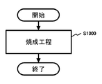
- FIG. 1 is a flowchart showing an example of the manufacturing method according to the first embodiment.
- FIG. 2 is a flowchart showing an example of the manufacturing method according to the first embodiment.
- FIG. 3 is a flowchart showing an example of the manufacturing method according to the first embodiment.
- FIG. 4 is a flowchart showing an example of the manufacturing method according to the second embodiment.
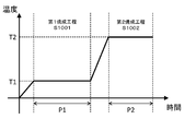
- FIG. 5 is a diagram showing an example of a firing temperature profile of the manufacturing method according to the second embodiment.
- FIG. 6 shows a schematic view of a pressure forming die 200 used for evaluating the ionic conductivity of a solid electrolyte material.
- FIG. 7 is a graph showing a Core-Cole plot obtained by measuring the impedance of the solid electrolyte material with Sample 1.
- FIG. 1 is a flowchart showing an example of the manufacturing method according to the first embodiment.
- the manufacturing method according to the first embodiment includes a firing step S1000.
- the mixed material is fired in an inert gas atmosphere.
- the mixed material fired in the firing step S1000 contains a Y-containing compound, a Sm-containing compound, NH 4 ⁇ , Li ⁇ , and Ca ⁇ 2 .
- the Y-containing compound is at least one selected from the group consisting of Y 2 O 3 and Y ⁇ 3.
- the compound containing Sm is at least one selected from the group consisting of Sm 2 O 3 and Sm ⁇ 3.
- the mixed material comprises at least one selected from the group consisting of Y 2 O 3 and Sm 2 O 3.
- ⁇ , ⁇ , ⁇ , and ⁇ are at least one independently selected from the group consisting of F, Cl, Br, and I, respectively.
- the production method according to the first embodiment is an industrially highly productive method for producing a halide.
- An industrially productive method is, for example, a method that can be mass-produced at low cost. That is, it contains Li (ie, lithium), Y (ie, yttrium), Sm (ie, samarium), and Ca (ie, calcium) by a simple manufacturing method (ie, firing in an inert gas atmosphere). Halides can be produced.
- the Y-containing compound and the Sm-containing compound are referred to as a Y-containing compound and a Sm-containing compound, respectively.
- the manufacturing method according to the first embodiment does not have to use a vacuum sealing tube and a planetary ball mill.
- the mixed material may contain Y 2 O 3 , Sm 2 O 3 , NH 4 ⁇ , Li ⁇ , and Ca ⁇ 2 . Since Y 2 O 3 , Sm 2 O 3 , NH 4 ⁇ , Li ⁇ , and Ca ⁇ 2 contained in the mixed material are inexpensive, the manufacturing cost can be reduced.
- ⁇ , ⁇ , ⁇ , ⁇ , and ⁇ may be at least one independently selected from the group consisting of Cl and Br, respectively.
- the powder of the mixed material may be placed in a container (for example, a crucible) and fired in a heating furnace. At this time, the state in which the mixed material has been heated to a predetermined temperature in the atmosphere of the inert gas may be maintained for a predetermined time or longer.
- the firing time may be such that the composition of the fired product does not deviate due to volatilization of the halide or the like.
- the time at which the composition of the fired product is not deviated means the firing time at which the ionic conductivity of the fired product is not impaired.
- a halide having an ionic conductivity of 6.0 ⁇ 10 -10 S / cm or more can be produced near room temperature.
- the inert gas atmosphere means, for example, an atmosphere in which the total concentration of gases other than the inert gas is 1% by volume or less.
- examples of the inert gas are helium, nitrogen, or argon.
- the fired product may be crushed.
- a crushing device for example, a mortar or a mixer
- a mortar or a mixer may be used.
- At least one selected from the group consisting of the Y-containing compound and the Sm-containing compound contained in the mixed material may have a part of the metal cation substituted with another metal cation. That is, a part of Y and Sm may be replaced by another metal cation. That is, the mixed material further contains a compound in which a part of Y is replaced by another metal cation in the Y-containing compound, or a compound in which a part of Sm is replaced by another metal cation in the Sm-containing compound. You may be. Thereby, the characteristics (for example, ionic conductivity) of the produced halide can be improved.
- the cation substitution rate of Y and Sm with another metal cation may be less than 50 mol%. As a result, a halide having a more stable structure can be obtained.
- At least one selected from the group consisting of Li ⁇ and Ca ⁇ 2 contained in the mixed material may be partially substituted with another metal cation. That is, a part of Li and Ca may be replaced by another metal cation. Therefore, the mixed material may further contain a compound in which a part of Li is replaced by another metal cation in Li ⁇ , or a compound in which a part of Ca is replaced by another metal cation in Ca ⁇ 2. good. Thereby, the characteristics (for example, ionic conductivity) of the produced halide can be improved.
- the cation substitution rate of Li and Ca with another metal cation may be less than 50 mol%. As a result, a halide having a more stable structure can be obtained.
- At least one selected from the group consisting of Y-containing compounds and Sm-containing compounds contained in the mixed material has a part of the metal cations, for example, Na, K, Mg, Sr, Ba, Zn, In, Sn, Bi. , La, Ce, Pr, Nd, Pm, Sm, Eu, Tb, Dy, Ho, Er, Tm, Yb, and Lu may be substituted with at least one cation selected from the group.
- the mixed material may be a material in which a Y-containing compound, a Sm-containing compound, NH 4 ⁇ , Li ⁇ , and Ca ⁇ 2 are mixed. That is, the mixed material may consist of a Y-containing compound, a Sm-containing compound, NH 4 ⁇ , Li ⁇ , and Ca ⁇ 2 .
- Y-containing compound, Sm-containing compounds, NH 4 ⁇ , Li ⁇ , and Caganma 2 as well, Y-containing compound, Sm-containing compounds, NH 4 ⁇ , Li ⁇ , and the Caganma 2 further comprise a different material You may.
- the mixed material may be fired at 350 ° C. or higher.
- the firing temperature is the ambient temperature. This makes it possible to produce a halide having high ionic conductivity by an industrially highly productive method.
- the mixed materials can be sufficiently reacted. That is, the Y-containing compound, the Sm-containing compound, NH 4 ⁇ , Li ⁇ , and Ca ⁇ 2 can be sufficiently reacted.
- the mixed material is calcined at 350 ° C. or higher, for example, a halide having an ionic conductivity of 1.0 ⁇ 10 -4 S / cm or higher can be produced near room temperature.
- the mixed material may be fired at 650 ° C. or lower.
- the mixed material may be calcined at, for example, 350 ° C. or higher and 650 ° C. or lower. This makes it possible to produce a halide having high ionic conductivity by an industrially highly productive method. By setting the calcination temperature to 650 ° C. or lower, thermal decomposition of the halide produced by the solid phase reaction can be suppressed.
- Y 2 O 3 , Sm 2 O 3 , and NH 4 ⁇ may be reacted with each other, and then Y 2 O 3 and Sm 2 O 3 may be halogenated.
- the calcination profile may then be set such that the halogenated Y 2 O 3 and Sm 2 O 3 react with Li ⁇ and Ca ⁇ 2.
- the calcination temperature may be lower than the sublimation point or melting point of NH 4 ⁇
- the halogenated Y 2 O 3 and Sm 2 O 3 may react with Li ⁇ and Ca ⁇ 2.
- the firing temperature may be a temperature lower than the sublimation point or melting point of NH 4 ⁇ and the temperature at which the halide solid electrolyte material is produced.
- the firing temperature in this reaction may be set to about 300 ° C. That is, the firing temperature may be set to a temperature lower than the sublimation point of NH 4 Cl, which is about 335 ° C., and a temperature at which the halide solid electrolyte material is produced.
- the calcination temperature may be 350 ° C. or higher in order to produce a halide having a higher ionic conductivity.
- the firing step is performed in two or more steps. At this time, the firing temperature in the first-stage firing step may be lower than the sublimation point of NH 4 ⁇ , and the firing temperature in the second and subsequent firing steps may be even higher.
- the mixed material may be fired in 1 hour or more and 72 hours or less. This makes it possible to produce a halide having high ionic conductivity by an industrially highly productive method.
- the firing time By setting the firing time to 1 hour or more, the mixed material can be sufficiently reacted. That is, the Y-containing compound, the Sm-containing compound, NH 4 ⁇ , Li ⁇ , and Ca ⁇ 2 can be sufficiently reacted.
- volatilization of the halide as a fired product can be suppressed. That is, a halide having the desired composition can be obtained.
- FIG. 2 is a flowchart showing an example of the manufacturing method according to the first embodiment.
- the production method according to the first embodiment may further include the mixing step S1100.
- the mixing step S1100 is executed before the firing step S1000.
- the mixing step S1100 the Y-containing compound, the Sm-containing compound, NH 4 ⁇ , Li ⁇ , and Ca ⁇ 2 as raw materials are mixed. As a result, a mixed material is obtained. That is, a material to be fired in the firing step S1000 is obtained.
- a known mixing device eg, mortar, blender, or ball mill
- mortar, blender, or ball mill may be used to mix the ingredients.
- the mixing step S1100 powders of each raw material may be prepared and mixed.
- the firing step S1000 the powdered mixed material may be fired.
- the powdery mixed material obtained in the mixing step S1100 may be formed into pellets by pressurization.
- the pellet-shaped mixed material may be fired.
- Y-containing compound, Sm-containing compounds, NH 4 ⁇ , Li ⁇ , and Caganma 2 as well, Y-containing compound, Sm-containing compounds, NH 4 ⁇ , Li ⁇ , and different materials are more and Caganma 2 By mixing, a mixed material may be obtained.
- a raw material containing a Y-containing compound as a main component a raw material containing an Sm-containing compound as a main component, a raw material containing NH 4 ⁇ as a main component, a raw material containing Li ⁇ as a main component, and Ca ⁇ 2 as a main component.
- the raw materials to be used may be mixed.
- the main component is the component contained most in the molar ratio.
- the Y-containing compound, the Sm-containing compound, NH 4 ⁇ , Li ⁇ , and Ca ⁇ 2 may be prepared and mixed so as to have the desired composition.
- the molar ratios of the Y-containing compound, the Sm-containing compound, NH 4 ⁇ , Li ⁇ , and Ca ⁇ 2 may be adjusted in advance so as to cancel the composition change that may occur in the firing step S1000.
- NH 4 ⁇ may be prepared in excess of Y 2 O 3 and Sm 2 O 3 in order to allow the synthetic reaction in the firing step S1000 to proceed satisfactorily.
- NH 4 ⁇ is prepared in an excess of 5 to 15 mol% over the sum of Y 2 O 3 and Sm 2 O 3.
- At least one selected from the group consisting of the Y-containing compound and the Sm-containing compound may have a part of the metal cation substituted with another metal cation. That is, a part of Y and Sm may be replaced by another metal cation. That is, a compound in which a part of Y is replaced by another metal cation in the Y-containing compound, or a compound in which a part of Sm is replaced by another metal cation in the Sm-containing compound is further mixed. , Mixed materials may be obtained.
- the cation substitution rate of Y and Sm with another metal cation may be less than 50 mol%.
- FIG. 3 is a flowchart showing an example of the manufacturing method according to the first embodiment.
- the manufacturing method according to the first embodiment may further include the preparation step S1200.
- the preparation step S1200 is executed before the mixing step S1100.
- raw materials such as Y-containing compound, Sm-containing compound, NH 4 ⁇ , Li ⁇ , and Ca ⁇ 2 are prepared. That is, the materials to be mixed in the mixing step S1100 are prepared.
- raw materials such as Y-containing compound, Sm-containing compound, NH 4 ⁇ , Li ⁇ , and Ca ⁇ 2 may be synthesized.
- a known commercially available product for example, a material having a purity of 99% or more may be used.
- the material to be prepared may be dry.
- the shape of the material to be prepared are crystalline, lumpy, flaky, or powdery.
- the raw material in the form of powder may be obtained by pulverizing the raw material in the form of crystals, lumps or flakes.
- At least one selected from the group consisting of the Y-containing compound and the Sm-containing compound may have a part of the metal cation substituted with another metal cation. That is, a part of Y and Sm may be replaced by another metal cation. That is, a compound in which a part of Y is replaced by another metal cation in the Y-containing compound, or a compound in which a part of Sm is replaced by another metal cation in the Sm-containing compound may be further prepared. ..
- the cation substitution rate of Y and Sm with another metal cation may be less than 50 mol%.
- the halide produced by the production method according to the first embodiment can be used as a solid electrolyte material.
- the solid electrolyte material is, for example, a solid electrolyte material having lithium ion conductivity.
- the solid electrolyte material is used, for example, in an all-solid-state lithium-ion secondary battery.
- FIG. 4 is a flowchart showing an example of the manufacturing method according to the second embodiment.
- the firing step S1000 includes a first firing step S1001 and a second firing step S1002.
- the second firing step S1002 is executed after the first firing step S1001.
- the mixed material is fired at the first firing temperature T1.
- the mixed material is fired at the second firing temperature T2.
- the second firing temperature T2 is 350 ° C. or higher and higher than the first firing temperature T1.
- the production method according to the second embodiment is an industrially highly productive method for producing a halide having higher ionic conductivity.
- the production method according to the second embodiment will be described with reference to an example in which the mixed material contains Y 2 O 3 and Sm 2 O 3.
- Y 2 O 3 and Sm 2 O 3 react with each other. That is, Y 2 O 3 and Sm 2 O 3 are halogenated.
- the halogenated Y 2 O 3 and Sm 2 O 3 react with Li ⁇ and Ca ⁇ 2 at the second firing temperature T2.
- the halide which is a fired product has higher crystallinity.
- the ionic conductivity of the halide which is the fired product can be increased. That is, a high-quality halide solid electrolyte material can be obtained.
- the first calcination temperature T1 may be 160 ° C. or higher and lower than 350 ° C. in order to produce a halide having higher ionic conductivity by an industrially productive method.
- the first firing temperature T1 By setting the first firing temperature T1 to 160 ° C. or higher, Y 2 O 3 , Sm 2 O 3 , and NH 4 ⁇ can be sufficiently reacted.
- the first firing temperature T1 By setting the first firing temperature T1 to less than 350 ° C. , sublimation of NH 4 ⁇ can be suppressed. As a result, the ionic conductivity of the halide which is the fired product can be increased. That is, a high-quality halide solid electrolyte material can be obtained.
- the second calcination temperature T2 may be 350 ° C. or higher and 650 ° C. or lower in order to produce a halide having higher ionic conductivity by an industrially productive method.
- the mixed materials can be sufficiently reacted. That is, the Y-containing compound, the Sm-containing compound, NH 4 ⁇ , Li ⁇ , and Ca ⁇ 2 can be sufficiently reacted.
- the halide which is a fired product has higher crystallinity.
- thermal decomposition of the halide produced by the solid phase reaction can be suppressed.
- the ionic conductivity of the halide which is the fired product can be increased. That is, a high-quality halide solid electrolyte material can be obtained.
- FIG. 5 is a diagram showing an example of a firing temperature profile of the manufacturing method according to the second embodiment.
- the mixed material in the first firing step S1001, the mixed material may be fired during the first firing time P1. In the second firing step S1002, the mixed material may be fired during the second firing time P2.
- the first calcination time P1 may be 1 hour or more and 72 hours or less in order to produce a halide having higher ionic conductivity by an industrially productive method.
- the first firing time P1 is 1 hour or more, Y 2 O 3 , Sm 2 O 3 , and NH 4 ⁇ can be sufficiently reacted.
- the first firing time P1 is 72 hours or less, the volatilization of "reactants of Y 2 O 3 and NH 4 ⁇ " and "reactants of Sm 2 O 3 and NH 4 ⁇ " can be suppressed. That is, a halide having the desired composition can be obtained.
- the second calcination time P2 may be 1 hour or more and 72 hours or less in order to produce a halide having a higher ionic conductivity by an industrially productive method.
- the mixed material can be sufficiently reacted. That is, the Y-containing compound, the Sm-containing compound, NH 4 ⁇ , Li ⁇ , and Ca ⁇ 2 can be sufficiently reacted.
- the second firing time P2 is 72 hours or less, volatilization of the halide as a fired product can be suppressed. That is, a halide having the desired composition can be obtained.
- P1> P2 may be satisfied. That is, the first firing time P1 may be longer than the second firing time P2. This makes it possible to produce a halide having higher ionic conductivity by an industrially productive method.
- Y 2 O 3 , Sm 2 O 3 , and NH 4 ⁇ can be sufficiently reacted at the first firing temperature T1 and during the first firing time P1. That is, Y 2 O 3 and Sm 2 O 3 can be sufficiently halogenated.
- sufficiently halogenated Y 2 O 3 and Sm 2 O 3 react with Li ⁇ and Ca ⁇ 2 at the second firing temperature T2 and during the second firing time P2. ..
- the halide which is a fired product has higher crystallinity.
- the ionic conductivity of the halide which is the fired product can be increased. That is, a high-quality halide solid electrolyte material can be obtained.
- (NH 4 ) a Y ⁇ 3 + a (0 ⁇ a ⁇ 3) may be synthesized from Y 2 O 3 and NH 4 ⁇ .
- (NH 4 ) b Sm ⁇ 3 + b (0 ⁇ b ⁇ 3) may be synthesized from Sm 2 O 3 and NH 4 ⁇ .
- Y 2 O 3, Sm 2 O 3, NH 4 Cl, LiCl, and the CaCl 2 consider the case of synthesizing the Li 2.8 Ca 0.1 Y 0.8 Sm 0.2 Cl 6.
- the first firing temperature T1 is about 200 ° C.
- the second firing time T2 is about 500 ° C.
- NH 4 Cl reacts with Y 2 O 3 and Sm 2 O 3 without sublimation, and (NH 4 ) a Y ⁇ 3 + a (0 ⁇ a ⁇ 3) and ( NH 4 ) b Sm ⁇ 3 + b (0 ⁇ b ⁇ 3) is mainly generated.
- the firing step S1000 may include not only the first firing step S1001 and the second firing step S1002, but also another firing step. That is, the firing step S1000 may include three or more steps depending on the type of raw material or the number of raw materials).
- the halide produced by the production method of the present disclosure was evaluated as a solid electrolyte material.
- the resulting mixture was placed in an alumina crucible and calcined at 500 ° C. for 1 hour in a nitrogen atmosphere. That is, the firing times T1 and T2 were both 500 ° C.
- the resulting calcined product was crushed in an agate mortar. In this way, the solid electrolyte material according to Sample 1 was obtained.
- FIG. 6 shows a schematic view of a pressure forming die 200 used to evaluate the ionic conductivity of a solid electrolyte material.
- the pressure forming die 200 included a punch upper part 201, a frame type 202, and a punch lower part 203.
- the frame type 202 was formed of insulating polycarbonate.
- the upper punch 201 and the lower punch 203 were made of electron-conducting stainless steel.
- the impedance of the solid electrolyte material by Sample 1 was measured by the following method.
- the powder of the solid electrolyte material from Sample 1 was filled inside the pressure forming die 200 in a dry atmosphere having a dew point of -60 ° C. or lower. Inside the pressure forming die 200, a pressure of 300 MPa was applied to the solid electrolyte material according to Sample 1 using the punch upper part 201 and the punch lower part 203.
- the upper punch 201 and the lower punch 203 were connected to a potentiostat (Princeton Applied Research, VersaSTAT4) equipped with a frequency response analyzer.
- the upper part 201 of the punch was connected to the working electrode and the terminal for measuring the potential.
- the lower punch 203 was connected to the counter electrode and the reference electrode.
- the impedance of the solid electrolyte material was measured at room temperature by an electrochemical impedance measurement method.
- FIG. 7 is a graph showing a Core-Cole plot obtained by measuring the impedance of the solid electrolyte material with Sample 1.
- the real value of the impedance at the measurement point where the absolute value of the phase of the complex impedance is the smallest was regarded as the resistance value of the solid electrolyte material to ionic conduction. See the arrow R SE shown in FIG. 7 for the real value.
- the ionic conductivity was calculated based on the following mathematical formula (3).
- ⁇ (R SE ⁇ S / t) -1 ... (3)
- ⁇ represents ionic conductivity.
- S represents the contact area of the solid electrolyte material with the punch upper portion 201 (equal to the cross-sectional area of the hollow portion of the frame type 202 in FIG. 6).
- R represents the resistance value of the solid electrolyte material in the impedance measurement.
- t represents the thickness of the solid electrolyte material (that is, the thickness of the layer formed from the powder 101 of the solid electrolyte material in FIG. 6).
- sample 15 the solid electrolyte material from sample 15 was obtained in the same manner as in sample 4 except for the temperature T2.
- the temperature T2 is shown in Table 1.
- sample 16 the solid electrolyte material from sample 16 was obtained in the same manner as in sample 1 except for the firing temperature.
- the firing temperatures are shown in Table 1.
- the raw material 1 is an oxide or a halide containing Y.
- Raw material 2 is an oxide or halide containing Sm.
- Raw material 3 is ammonium halide.
- Raw material 4 is LiCl.
- the raw material 5 is LiBr.
- the raw material 6 is a halide containing Ca.
- the solid electrolyte material produced by the production method of the present disclosure has an ionic conductivity of 6.0 ⁇ 10 -10 S / cm or more in the vicinity of room temperature.
- the obtained solid electrolyte material has a high ionic conductivity of 1.0 ⁇ 10 -4 S / cm or higher in the vicinity of room temperature. Have a degree.
- the solid electrolyte material has higher ionic conductivity when the temperature T1 is 180 ° C. or higher and 350 or lower. Has.
- the solid electrolyte material has higher ionic conductivity when the temperature T2 is 500 ° C. or higher and 600 or lower. Have.
- the solid electrolyte material has higher ionic conductivity when the Y-containing compound and the Sm-containing compound are oxides than chlorides.
- the halide produced by the production method of the present disclosure has high lithium ion conductivity.
- the manufacturing method of the present disclosure is a simple method and is an industrially highly productive method.
- An industrially productive method is, for example, a method that can be mass-produced at low cost.
- the manufacturing method of the present disclosure is used, for example, as a manufacturing method of a solid electrolyte material.
- the solid electrolyte material produced by the production method of the present disclosure is used, for example, in an all-solid-state lithium ion secondary battery.
- Solid electrolyte material powder 200 Pressure forming die 201 Punch upper part 202 Frame type 203 Punch lower part
Landscapes
- Chemical & Material Sciences (AREA)
- Inorganic Chemistry (AREA)
- Organic Chemistry (AREA)
- Engineering & Computer Science (AREA)
- Manufacturing & Machinery (AREA)
- Chemical Kinetics & Catalysis (AREA)
- Electrochemistry (AREA)
- General Chemical & Material Sciences (AREA)
- Geology (AREA)
- Physics & Mathematics (AREA)
- Condensed Matter Physics & Semiconductors (AREA)
- General Physics & Mathematics (AREA)
- Life Sciences & Earth Sciences (AREA)
- Materials Engineering (AREA)
- Conductive Materials (AREA)
- Compounds Of Alkaline-Earth Elements, Aluminum Or Rare-Earth Metals (AREA)
Abstract
La présente invention concerne un procédé de production qui comprend une étape de cuisson consistant à procéder à la cuisson, sous une atmosphère de gaz inerte, d'un matériau mixte comprenant un composé contenant de l'Y, un composé contenant du Sm, du NH4α, du Liβ et du Caγ2. Le composé contenant de l'Y est au moins un élément choisi dans le groupe constitué par l'Y2O3 et l'Yδ3 ; le composé contenant du Sm est au moins un élément choisi dans le groupe constitué par le Sm2O3 et le Smε3 ; et le matériau mixte contient au moins un élément choisi dans le groupe constitué par l'Y2O3 et le Sm2O3. α, β, γ, δ et ε représentent chacun indépendamment au moins un élément choisi dans le groupe constitué par F, Cl, Br et I.
Priority Applications (4)
| Application Number | Priority Date | Filing Date | Title |
|---|---|---|---|
| EP21780196.8A EP4129914B1 (fr) | 2020-03-31 | 2021-01-25 | Procédé de production d'halogénure |
| JP2022511576A JP7650006B2 (ja) | 2020-03-31 | 2021-01-25 | ハロゲン化物の製造方法 |
| CN202180019547.4A CN115244002A (zh) | 2020-03-31 | 2021-01-25 | 卤化物的制造方法 |
| US17/933,097 US12180085B2 (en) | 2020-03-31 | 2022-09-17 | Method for producing halide |
Applications Claiming Priority (2)
| Application Number | Priority Date | Filing Date | Title |
|---|---|---|---|
| JP2020064816 | 2020-03-31 | ||
| JP2020-064816 | 2020-03-31 |
Related Child Applications (1)
| Application Number | Title | Priority Date | Filing Date |
|---|---|---|---|
| US17/933,097 Continuation US12180085B2 (en) | 2020-03-31 | 2022-09-17 | Method for producing halide |
Publications (1)
| Publication Number | Publication Date |
|---|---|
| WO2021199620A1 true WO2021199620A1 (fr) | 2021-10-07 |
Family
ID=77930281
Family Applications (1)
| Application Number | Title | Priority Date | Filing Date |
|---|---|---|---|
| PCT/JP2021/002516 Ceased WO2021199620A1 (fr) | 2020-03-31 | 2021-01-25 | Procédé de production d'halogénures |
Country Status (5)
| Country | Link |
|---|---|
| US (1) | US12180085B2 (fr) |
| EP (1) | EP4129914B1 (fr) |
| JP (1) | JP7650006B2 (fr) |
| CN (1) | CN115244002A (fr) |
| WO (1) | WO2021199620A1 (fr) |
Cited By (2)
| Publication number | Priority date | Publication date | Assignee | Title |
|---|---|---|---|---|
| JPWO2022158422A1 (fr) * | 2021-01-19 | 2022-07-28 | ||
| JPWO2022239352A1 (fr) * | 2021-05-10 | 2022-11-17 |
Citations (6)
| Publication number | Priority date | Publication date | Assignee | Title |
|---|---|---|---|---|
| CN104357051A (zh) * | 2014-11-10 | 2015-02-18 | 朝克夫 | 一种荧光材料及其制备方法,和发光装置 |
| CN106745163A (zh) * | 2015-11-24 | 2017-05-31 | 有研稀土新材料股份有限公司 | 高纯无水复合稀土卤化物及其制备方法 |
| WO2018025582A1 (fr) | 2016-08-04 | 2018-02-08 | パナソニックIpマネジメント株式会社 | Matériau d'électrolyte solide, et cellule |
| WO2019135344A1 (fr) * | 2018-01-05 | 2019-07-11 | パナソニックIpマネジメント株式会社 | Matériau d'électrolyte solide, et batterie |
| WO2019135328A1 (fr) * | 2018-01-05 | 2019-07-11 | パナソニックIpマネジメント株式会社 | Matériau d'électrolyte solide et batterie |
| JP2019145489A (ja) * | 2018-02-21 | 2019-08-29 | パナソニックIpマネジメント株式会社 | 固体電解質の製造方法、固体電解質、活物質層、活物質層の形成方法、セパレータ層、セパレータ層の形成方法及び全固体電池 |
Family Cites Families (8)
| Publication number | Priority date | Publication date | Assignee | Title |
|---|---|---|---|---|
| FR2648802B1 (fr) * | 1989-06-22 | 1991-09-20 | Rhone Poulenc Chimie | Melanges deshydrates d'halogenures de terres rares et d'alcalino-terreux ou d'alcalins |
| US20040016632A1 (en) * | 2002-07-26 | 2004-01-29 | Jeremy Barker | Methods of making transition metal compounds useful as cathode active materials using electromagnetic radiation |
| CN100590173C (zh) * | 2006-03-24 | 2010-02-17 | 北京有色金属研究总院 | 一种荧光粉及其制造方法和所制成的电光源 |
| WO2008093801A1 (fr) * | 2007-02-02 | 2008-08-07 | Asahi Glass Company, Limited | Procédé de fabrication d'une fine particule de solution solide |
| JP6467238B2 (ja) * | 2015-02-09 | 2019-02-06 | 東日本旅客鉄道株式会社 | レール転倒防止装置 |
| US20180183046A1 (en) * | 2016-12-28 | 2018-06-28 | Lg Chem, Ltd. | Positive electrode active material for lithium secondary battery, method for preparing the same, and lithium secondary battery including the same |
| EP4131506A4 (fr) * | 2020-03-31 | 2023-09-27 | Panasonic Intellectual Property Management Co., Ltd. | Matériau d'électrolyte solide et batterie l'utilisant |
| EP4131500A4 (fr) * | 2020-03-31 | 2023-09-27 | Panasonic Intellectual Property Management Co., Ltd. | Matériau d'électrolyte solide et batterie l'utilisant |
-
2021
- 2021-01-25 JP JP2022511576A patent/JP7650006B2/ja active Active
- 2021-01-25 EP EP21780196.8A patent/EP4129914B1/fr active Active
- 2021-01-25 CN CN202180019547.4A patent/CN115244002A/zh active Pending
- 2021-01-25 WO PCT/JP2021/002516 patent/WO2021199620A1/fr not_active Ceased
-
2022
- 2022-09-17 US US17/933,097 patent/US12180085B2/en active Active
Patent Citations (6)
| Publication number | Priority date | Publication date | Assignee | Title |
|---|---|---|---|---|
| CN104357051A (zh) * | 2014-11-10 | 2015-02-18 | 朝克夫 | 一种荧光材料及其制备方法,和发光装置 |
| CN106745163A (zh) * | 2015-11-24 | 2017-05-31 | 有研稀土新材料股份有限公司 | 高纯无水复合稀土卤化物及其制备方法 |
| WO2018025582A1 (fr) | 2016-08-04 | 2018-02-08 | パナソニックIpマネジメント株式会社 | Matériau d'électrolyte solide, et cellule |
| WO2019135344A1 (fr) * | 2018-01-05 | 2019-07-11 | パナソニックIpマネジメント株式会社 | Matériau d'électrolyte solide, et batterie |
| WO2019135328A1 (fr) * | 2018-01-05 | 2019-07-11 | パナソニックIpマネジメント株式会社 | Matériau d'électrolyte solide et batterie |
| JP2019145489A (ja) * | 2018-02-21 | 2019-08-29 | パナソニックIpマネジメント株式会社 | 固体電解質の製造方法、固体電解質、活物質層、活物質層の形成方法、セパレータ層、セパレータ層の形成方法及び全固体電池 |
Non-Patent Citations (1)
| Title |
|---|
| See also references of EP4129914A4 |
Cited By (3)
| Publication number | Priority date | Publication date | Assignee | Title |
|---|---|---|---|---|
| JPWO2022158422A1 (fr) * | 2021-01-19 | 2022-07-28 | ||
| JP7667186B2 (ja) | 2021-01-19 | 2025-04-22 | 出光興産株式会社 | ハロゲン化リチウムの製造方法及び硫化物固体電解質の製造方法 |
| JPWO2022239352A1 (fr) * | 2021-05-10 | 2022-11-17 |
Also Published As
| Publication number | Publication date |
|---|---|
| US12180085B2 (en) | 2024-12-31 |
| EP4129914A4 (fr) | 2023-09-27 |
| EP4129914B1 (fr) | 2024-08-07 |
| CN115244002A (zh) | 2022-10-25 |
| EP4129914A1 (fr) | 2023-02-08 |
| US20230018638A1 (en) | 2023-01-19 |
| JP7650006B2 (ja) | 2025-03-24 |
| JPWO2021199620A1 (fr) | 2021-10-07 |
Similar Documents
| Publication | Publication Date | Title |
|---|---|---|
| JP7186405B2 (ja) | ハロゲン化物の製造方法 | |
| JP7365599B2 (ja) | ハロゲン化物の製造方法 | |
| JP7186404B2 (ja) | ハロゲン化物の製造方法 | |
| JP7365600B2 (ja) | ハロゲン化物の製造方法 | |
| US12180085B2 (en) | Method for producing halide | |
| JP7357299B2 (ja) | ハロゲン化物の製造方法 | |
| JP7702662B2 (ja) | ハロゲン化物の製造方法 | |
| JP7702661B2 (ja) | ハロゲン化物の製造方法 | |
| JP7378039B2 (ja) | ハロゲン化物の製造方法 | |
| JP7650007B2 (ja) | ハロゲン化物の製造方法 | |
| JP7650005B2 (ja) | ハロゲン化物の製造方法 |
Legal Events
| Date | Code | Title | Description |
|---|---|---|---|
| 121 | Ep: the epo has been informed by wipo that ep was designated in this application |
Ref document number: 21780196 Country of ref document: EP Kind code of ref document: A1 |
|
| ENP | Entry into the national phase |
Ref document number: 2022511576 Country of ref document: JP Kind code of ref document: A |
|
| NENP | Non-entry into the national phase |
Ref country code: DE |
|
| ENP | Entry into the national phase |
Ref document number: 2021780196 Country of ref document: EP Effective date: 20221031 |