WO2021199639A1 - 光学装置 - Google Patents
光学装置 Download PDFInfo
- Publication number
- WO2021199639A1 WO2021199639A1 PCT/JP2021/003279 JP2021003279W WO2021199639A1 WO 2021199639 A1 WO2021199639 A1 WO 2021199639A1 JP 2021003279 W JP2021003279 W JP 2021003279W WO 2021199639 A1 WO2021199639 A1 WO 2021199639A1
- Authority
- WO
- WIPO (PCT)
- Prior art keywords
- nozzle
- observation window
- hydrophobic
- water
- region
- Prior art date
- Legal status (The legal status is an assumption and is not a legal conclusion. Google has not performed a legal analysis and makes no representation as to the accuracy of the status listed.)
- Ceased
Links
Images









Classifications
-
- A—HUMAN NECESSITIES
- A61—MEDICAL OR VETERINARY SCIENCE; HYGIENE
- A61B—DIAGNOSIS; SURGERY; IDENTIFICATION
- A61B1/00—Instruments for performing medical examinations of the interior of cavities or tubes of the body by visual or photographical inspection, e.g. endoscopes; Illuminating arrangements therefor
- A61B1/12—Instruments for performing medical examinations of the interior of cavities or tubes of the body by visual or photographical inspection, e.g. endoscopes; Illuminating arrangements therefor with cooling or rinsing arrangements
- A61B1/126—Instruments for performing medical examinations of the interior of cavities or tubes of the body by visual or photographical inspection, e.g. endoscopes; Illuminating arrangements therefor with cooling or rinsing arrangements provided with means for cleaning in-use
-
- A—HUMAN NECESSITIES
- A61—MEDICAL OR VETERINARY SCIENCE; HYGIENE
- A61B—DIAGNOSIS; SURGERY; IDENTIFICATION
- A61B1/00—Instruments for performing medical examinations of the interior of cavities or tubes of the body by visual or photographical inspection, e.g. endoscopes; Illuminating arrangements therefor
- A61B1/00064—Constructional details of the endoscope body
- A61B1/00071—Insertion part of the endoscope body
- A61B1/00075—Insertion part of the endoscope body with externally roughened shaft
-
- A—HUMAN NECESSITIES
- A61—MEDICAL OR VETERINARY SCIENCE; HYGIENE
- A61B—DIAGNOSIS; SURGERY; IDENTIFICATION
- A61B1/00—Instruments for performing medical examinations of the interior of cavities or tubes of the body by visual or photographical inspection, e.g. endoscopes; Illuminating arrangements therefor
- A61B1/00064—Constructional details of the endoscope body
- A61B1/00071—Insertion part of the endoscope body
- A61B1/0008—Insertion part of the endoscope body characterised by distal tip features
- A61B1/00091—Nozzles
-
- A—HUMAN NECESSITIES
- A61—MEDICAL OR VETERINARY SCIENCE; HYGIENE
- A61B—DIAGNOSIS; SURGERY; IDENTIFICATION
- A61B1/00—Instruments for performing medical examinations of the interior of cavities or tubes of the body by visual or photographical inspection, e.g. endoscopes; Illuminating arrangements therefor
- A61B1/00064—Constructional details of the endoscope body
- A61B1/00071—Insertion part of the endoscope body
- A61B1/0008—Insertion part of the endoscope body characterised by distal tip features
- A61B1/00096—Optical elements
-
- B—PERFORMING OPERATIONS; TRANSPORTING
- B08—CLEANING
- B08B—CLEANING IN GENERAL; PREVENTION OF FOULING IN GENERAL
- B08B3/00—Cleaning by methods involving the use or presence of liquid or steam
- B08B3/02—Cleaning by the force of jets or sprays
-
- B—PERFORMING OPERATIONS; TRANSPORTING
- B08—CLEANING
- B08B—CLEANING IN GENERAL; PREVENTION OF FOULING IN GENERAL
- B08B5/00—Cleaning by methods involving the use of air flow or gas flow
- B08B5/02—Cleaning by the force of jets, e.g. blowing-out cavities
-
- G—PHYSICS
- G02—OPTICS
- G02B—OPTICAL ELEMENTS, SYSTEMS OR APPARATUS
- G02B1/00—Optical elements characterised by the material of which they are made; Optical coatings for optical elements
- G02B1/10—Optical coatings produced by application to, or surface treatment of, optical elements
- G02B1/18—Coatings for keeping optical surfaces clean, e.g. hydrophobic or photo-catalytic films
-
- G—PHYSICS
- G02—OPTICS
- G02B—OPTICAL ELEMENTS, SYSTEMS OR APPARATUS
- G02B23/00—Telescopes, e.g. binoculars; Periscopes; Instruments for viewing the inside of hollow bodies; Viewfinders; Optical aiming or sighting devices
- G02B23/24—Instruments or systems for viewing the inside of hollow bodies, e.g. fibrescopes
-
- G—PHYSICS
- G02—OPTICS
- G02B—OPTICAL ELEMENTS, SYSTEMS OR APPARATUS
- G02B23/00—Telescopes, e.g. binoculars; Periscopes; Instruments for viewing the inside of hollow bodies; Viewfinders; Optical aiming or sighting devices
- G02B23/24—Instruments or systems for viewing the inside of hollow bodies, e.g. fibrescopes
- G02B23/2407—Optical details
- G02B23/2423—Optical details of the distal end
-
- G—PHYSICS
- G02—OPTICS
- G02B—OPTICAL ELEMENTS, SYSTEMS OR APPARATUS
- G02B27/00—Optical systems or apparatus not provided for by any of the groups G02B1/00 - G02B26/00, G02B30/00
- G02B27/0006—Optical systems or apparatus not provided for by any of the groups G02B1/00 - G02B26/00, G02B30/00 with means to keep optical surfaces clean, e.g. by preventing or removing dirt, stains, contamination, condensation
Definitions
- the technology disclosed in this disclosure relates to an optical device.
- An endoscope is known as an example of an optical device having an optical window through which light enters or exits.
- an observation window in which the light of the subject to be imaged is incident is provided at the tip of the insertion portion of the endoscope.
- a nozzle for cleaning the deposits adhering to the observation window is provided on the arrangement surface on which the observation window is arranged.
- the nozzle is provided with an opening for injecting a liquid such as water and a gas such as air for blowing off water droplets.
- the observation window is projected at a predetermined height from the flat portion of the tip cover disposed at the tip of the insertion portion, and the circular peripheral edge is formed around the circular peripheral edge of the observation window.
- An endoscope provided with an inclined portion formed in a tapered shape from the portion to the outside is disclosed. At least a part of the surface of the inclined portion is hydrophilic.
- the technique of the present disclosure has been made in view of the above circumstances, and provides an optical device that is easier to remove the residual liquid than before when the residual liquid remaining in the observation window is removed by the air supply from the nozzle.
- the purpose is easier to remove the residual liquid than before when the residual liquid remaining in the observation window is removed by the air supply from the nozzle.
- the optical device of the present disclosure includes an optical window and a nozzle for air supply and liquid supply that has an opening for injecting gas and liquid and cleans an effective area of the optical window by selectively injecting gas and liquid.
- the second hydrophobic portion is formed in the region adjacent to the effective region on the downstream side in the injection direction of the nozzle with the effective region in between.
- a hydrophilic portion having hydrophilic surface characteristics is formed in a region outside the two tangents and adjacent to the first hydrophobic portion.
- the hydrophilic part preferably extends along the tangent line to the downstream side of the effective region.
- At least the effective region of the optical window has hydrophobicity.
- the first hydrophobic portion may have a first fine concavo-convex structure in which a plurality of convex portions are periodically arranged.
- the distance between the tip surfaces of the convex portions is preferably 0.1 ⁇ m or more and 10 ⁇ m or less.
- the height of the convex portion of the first fine concavo-convex structure is preferably 2 ⁇ m or more and 50 ⁇ m or less.
- the hydrophilic portion may have a second fine concavo-convex structure in which a plurality of convex portions are randomly arranged.
- the surface roughness of the second fine uneven structure is preferably 0.5 ⁇ m or more and 1 ⁇ m or less.
- FIG. 1 It is a figure which shows the whole block diagram of an endoscope apparatus. It is a top view which looked at the endoscope from the tip side. It is a cross-sectional view of the tip of the insertion part of an endoscope, and is the cross-sectional view taken along line AA in FIG. Are shown respectively. It is a perspective view of the tip part of an endoscope. It is a perspective view of the first fine concavo-convex structure. It is a top view seen from the tip side of the endoscope of the first fine concavo-convex structure. It is a perspective view of the 2nd fine concavo-convex structure. It is a figure for demonstrating the action at the time of air supply and water supply in an endoscope. FIG.
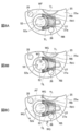
- FIG. 8A shows a state in which water is jetted from a nozzle toward an observation window
- FIG. The state of injecting air from the nozzle toward the observation window is shown. It is a figure for demonstrating the action at the time of air supply and water supply in a conventional endoscope
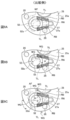
- FIG. 9A is a state which sprayed water from a nozzle toward an observation window
- FIG. 9B is a state where water injection was stopped.
- Reference numeral 9C shows a state in which air is injected from the nozzle toward the observation window. It is a top view which looked at the endoscope from the tip side. It is a top view which looked at the endoscope from the tip side. It is sectional drawing of the tip of the insertion part of an endoscope.
- FIG. 1 is a diagram showing an overall configuration diagram of an endoscope device 11 including an endoscope according to the first embodiment of the present disclosure.
- the endoscope device 11 includes an endoscope 12, a control device 13, a light source device 14, and an air supply / water supply device 15.
- the endoscope 12 is connected to a flexible insertion portion 16 inserted into the body of the subject and a proximal end portion of the insertion portion 16 and is used for gripping the endoscope 12 and operating the insertion portion 16. It includes an operation unit 17 and a universal cord 19 that connects the operation unit 17 to the control device 13 and the light source device 14.
- the insertion portion 16 is connected to the tip portion 16a in which the imaging unit 30 (see FIG. 3) is built, the bendable bending portion 16b connected to the base end of the tip portion 16a, and the base end of the bending portion 16b. It is provided with a flexible tube portion 16c having a flexibility.
- the base end means one end on the operation unit 17 side of both ends of each member.
- the operation unit 17 is provided with an operation member including an angle knob 21 for bending the curved portion 16b up, down, left and right, and an air supply / water supply button 22 for ejecting air and water from the tip portion 16a. .. Further, the operation unit 17 is provided with an inlet-side forceps opening (not shown) for inserting a treatment tool such as an electric knife into the forceps channel inserted into the insertion unit 16.
- the control device 13 is electrically connected to the light source device 14 and comprehensively controls the operation of the endoscope device 11.
- the control device 13 supplies power to the endoscope 12 via a transmission cable inserted into the universal cord 19 and the insertion unit 16 to control the drive of the image sensor 82 (see FIG. 3). Further, the control device 13 acquires an image pickup signal output from the image pickup device 82 via a transmission cable, performs various image processing, and generates image data.
- the image data generated by the control device 13 is displayed as an observation image on the monitor 20 connected to the control device 13 by a cable.
- the light source device 14 has, for example, a semiconductor light source such as an LED (Light Emitting Diode), and emits light to the tip portion 16a of the endoscope 12 via a universal cord 19 and a light guide inserted into the insertion portion 16. Supply.
- a semiconductor light source such as an LED (Light Emitting Diode)
- LED Light Emitting Diode
- the air supply / water supply device 15 is a well-known air supply device (for example, a pump or the like) 15a built in the light source device 14 to supply air, and wash water provided outside the light source device 14 to store wash water. It is composed of a tank 15b.
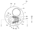
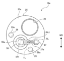
- FIG. 2 is a plan view of the endoscope as viewed from the tip side.
- FIG. 3 is a cross-sectional view of the tip of the insertion portion of the endoscope, and is a cross-sectional view taken along the line AA in FIG.
- an observation window 52 As shown in FIG. 2, on the tip surface of the tip portion 16a, that is, the tip surface 25a of the tip protection cap 25, an observation window 52, two illumination windows 26, a nozzle 27 for supplying air and water, and forceps on the outlet side are provided. A mouth 28 and a mouth 28 are provided.
- the tip protection cap 25 is made of a resin material such as polysulfone.
- the illumination window 26 emits light supplied from the light source device 14 and guided by the light guide from the light emitting surface 26a toward the observation target in the body cavity.
- the observation window 52 is a window that captures the light reflected by the observation target into the tip portion 16a.
- the observation window 52 functions as the most advanced lens in the objective optical system 51 of the image pickup unit 30 (see FIG. 3).
- the observation window 52 is an example of an optical window according to the technique of the present disclosure.
- the entire area of the light incident surface 52a of the observation window 52 is the effective region.
- the effective region in the observation window 52 is at least a part of the light incident surface 52a, and is a region through which an effective light flux contributing to imaging passes. More specifically, among the light passing through the observation window 52, the light that reaches the imaging surface 84 (see FIG. 3) without being eclipsed in the middle is an effective luminous flux that contributes to imaging, and is an effective luminous flux on the light incident surface 52a.
- the region defined by the passage position of the maximum peripheral light beam of the effective luminous flux is referred to as an effective region.
- all the light passing through the light incident surface 52a is effective light that contributes to imaging. In this case, the entire area of the light incident surface 52a is the effective area of the observation window 52.
- the two illumination windows 26 are arranged symmetrically on both sides of the observation window 52.
- the opening 27a of the nozzle 27 is arranged toward the observation window 52 at a position adjacent to the observation window 52.
- the nozzle 27 selectively injects air and water from the opening 27a into the observation window 52 in response to the operation of the air supply / water supply button 22.
- the nozzle 27 for air supply and water supply is an example of a nozzle for air supply and liquid supply according to the technique of the present disclosure.
- the tip portion 16a includes a tip rigid portion 24 and a tip protection cap 25 attached to the tip side of the tip rigid portion 24.
- the tip rigid portion 24 is made of a metal such as stainless steel, and a plurality of through holes are formed along the longitudinal direction.
- Various parts such as an image pickup unit 30, an air supply / water supply channel 32, a forceps channel (not shown), and a light guide (not shown) are inserted and fixed in each through hole of the tip rigid portion 24.
- the rear end of the tip rigid portion 24 is connected to the tip of the bending piece 33 constituting the bending portion 16b. Further, the outer circumference of the tip rigid portion 24 is covered with an outer skin tube 34.
- the image pickup unit 30 is formed on an objective optical system 51 that forms an image of light incident from the observation window 52 on the image pickup surface 84 of the image pickup element 82, a lens barrel 50 that holds the objective optical system 51, and a base end 50a of the lens barrel 50. It includes a connected prism 60, a cover glass 40 bonded to the prism 60, and an image pickup element substrate 80 arranged so as to face the light emitting surface 60b of the prism 60.
- the objective optical system 51 includes an observation window 52 that functions as a lens, a lens 53, and a lens 54.
- the lens barrel 50 holds the observation window 52, the lens 53, and the lens 54 inside.
- An image pickup device 82 having an image pickup surface 84 is provided on a part of the image pickup element substrate 80, and the cover glass 40 is arranged on the image pickup surface 84 of the image pickup element 82.
- a circuit unit 83 is provided at the rear end of the image sensor substrate 80. The circuit unit 83 has a function of processing the image pickup signal output by the image pickup device 82 and transferring it to the control device 13.
- the air supply / water supply nozzle 27 is connected to the air supply / water supply device 15 via the air supply / water supply channel 32.
- an observation window 52 and a nozzle 27 are arranged on the tip surface 25a of the tip protection cap 25.
- the tip surface 25a is an example of an arrangement surface according to the technique of the present disclosure.
- the tip surface 25a includes a first hydrophobic portion RA1 having a hydrophobic surface property.
- the first hydrophobic portion RA1 is formed in a part of the tip surface 25a existing between the observation window 52 and the nozzle 27. More specifically, the region where the first hydrophobic portion RA1 is formed intersects the injection direction ID of the nozzle 27 and is observed from both ends of the opening 27a of the nozzle 27 in the width direction WD along the tip surface 25a. It is the entire region between the two tangents TL drawn with respect to the light incident surface 52a of 52. In this example, the entire area of the light incident surface 52a is an effective region according to the technique of the present disclosure, as described above. In this example, the two tangent lines TL circumscribe the outer edge of the light incident surface 52a.
- hydrophilcity means a characteristic that the static contact angle with respect to pure water is 110 ° or more.
- one end point of the two tangent lines TL is an intersection 27c between the end portion 27b of the opening 27a and the tip surface 25a in the width direction WD. Then, the two tangent lines TL extend from each of the intersections 27c toward the light incident surface 52a of the observation window 52. The other end point of the two tangent lines TL serves as a contact point circumscribing the outer edge of the light incident surface 52a.
- the region where the first hydrophobic portion RA1 is formed extends in the width direction WD of the two tangent lines TL, a part of the outer edge of the light incident surface 52a, and the opening 27a, as shown by thin hatching in FIGS. 2 and 4. It is an area partitioned by sides.
- the first hydrophobic portion RA1 is composed of a first fine concavo-convex structure in which a plurality of convex portions are periodically arranged.
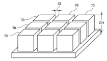
- the first fine concavo-convex structure is a structure in which a plurality of convex portions 70 having a quadrangular prism shape and substantially the same height are arranged at equal intervals in a grid pattern.
- the distance CI between the tip surfaces of the convex portions 70 is 0.1 ⁇ m or more and 10 ⁇ m or less.
- the height CH of the convex portion 70 is 2 ⁇ m or more and 50 ⁇ m or less.
- the first fine concavo-convex structure is formed by cutting a groove between the convex portions 70 with an ultrashort pulse laser having a pulse width of femtoseconds to several picoseconds on the first hydrophobic portion RA1 of the tip surface 25a. It is formed.
- hydrophilic portion having hydrophilic surface characteristics is located outside the two tangent lines TL and adjacent to the first hydrophobic portion RA1.
- RB is formed.
- hydrophilic means a characteristic that the static contact angle with respect to pure water is 15 ° or less.
- the region where the hydrophilic portion RB is formed is a range from one end to the other end of the tangent line TL in the injection direction ID, and is partitioned by a line parallel to the tangent line TL in the width direction WD.
- the width of the WD in the width direction of the hydrophilic portion RB is preferably a width that can hold the water flowing from the first hydrophobic portion RA1 into the hydrophilic portion RB to such an extent that it does not flow back into the first hydrophobic portion RA1.
- the boundary of the hydrophilic portion RB on the nozzle 27 side is set to a line OL (see FIG. 2) extending in the width direction WD at the edge of the nozzle 27 on the observation window 52 side.
- the hydrophilic portion RB is composed of a second fine concavo-convex structure in which a plurality of convex portions 75 having different heights are randomly arranged.
- the second fine uneven structure has a surface roughness of 0.5 ⁇ m or more and 1 ⁇ m or less.
- the second fine concavo-convex structure is formed by randomly performing cutting and melting with an ultrashort pulse laser over the entire area of the hydrophilic portion RB of the tip surface 25a.
- the effective region of the observation window 52 which is an example of the optical window, has hydrophobicity.
- the entire area of the light incident surface 52a is the effective region, the entire area of the light incident surface 52a has hydrophobicity.
- the light incident surface 52a of the observation window 52 is processed to be hydrophobic by an ultrashort pulse laser, similarly to the first hydrophobic portion RA1.
- water WF is injected from the opening 27a of the nozzle 27 toward the light incident surface 52a of the observation window 52.
- the water WF passes through the first hydrophobic portion RA1 from the nozzle 27 and heads toward the light incident surface 52a.
- the jetted water WF washes away the deposits adhering to the light incident surface 52a.
- not all the water WF ejected from the nozzle 27 reaches the light incident surface 52a, and water droplets WG that do not reach the light incident surface 52a are generated.
- the water droplet WG that does not reach the light incident surface 52a tends to stay in the first hydrophobic portion RA1 in the region between the nozzle 27 and the light incident surface 52a.
- the first hydrophobic portion RA1 has a hydrophobic surface property
- the water droplet WG is hard to get wet and repels the water droplet WG. Therefore, the water droplet WG does not stay at the first hydrophobic portion RA1 but flows outward due to the momentum of the injection.
- a hydrophilic portion RB is provided adjacent to the first hydrophobic portion RA1. Since the water droplet WG tends to get wet in the hydrophilic portion RB, the water droplet WG that has flowed out from the first hydrophobic portion RA1 is likely to be guided to the hydrophilic portion RB. Further, the water droplet WG induced in the hydrophilic portion RB does not easily flow back into the first hydrophobic portion RA1, and the water droplet WG remains on the hydrophilic portion RB as shown in FIG. 8B.
- the air AF when the air AF is injected, the water droplet WG on the light incident surface 52a of the observation window 52 is removed by the air AF.
- the air AF ejected from the nozzle 27 passes through the first hydrophobic portion RA1 from the nozzle 27 and heads toward the light incident surface 52a in the same manner as the water WF.
- the region between the nozzle 27 and the observation window 52 is the first hydrophobic portion RA1 having hydrophobic surface characteristics. Therefore, as shown in FIG. 8B, after the water WF is injected, the water droplets WG are unlikely to remain in the first hydrophobic portion RA1, so that even when the air AF is injected, the first hydrophobic portion is caught in the air AF. Water droplets WG from RA1 toward the light incident surface 52a are reduced. Therefore, when the water droplet WG remaining on the light incident surface 52a is removed by the injection of the air AF, another water droplet WG remaining on the flow path of the air AF adheres to the light incident surface 52a by the injected air AF. Is suppressed. Further, a part of the water droplets WG remaining on the hydrophilic portion RB is blown to the outside of the hydrophilic portion RB by the air AF.
- FIG. 9 showing a comparative example, an example of a conventional endoscope not provided with the first hydrophobic portion RA1 is shown.
- FIG. 9A when the water WF is injected from the opening 27a of the nozzle 27 toward the observation window 52, the injected water WF passes through the region RN between the observation window 52 and the nozzle 27. do.
- FIG. 9B when the surface characteristics of the region RN are not hydrophobic, a part of the sprayed water WF remains on the region RN as water droplets WG in a large amount.
- the endoscope 12 of the present embodiment is a part of the tip surface 25a (an example of the arrangement surface) existing between the observation window 52 (an example of an optical window) and the nozzle 27, as described above.
- the water droplet WG is placed on the first hydrophobic portion RA1 between the observation window 52 and the nozzle 27. Is hard to remain.
- the air supply for injecting the air AF is performed in order to remove the water droplets WG remaining in the observation window 52. Even when air is supplied, another water droplet WG is caught in the air AF from the first hydrophobic portion RA1 between the observation window 52 and the nozzle 27 and moves onto the light incident surface 52a of the observation window 52. Is suppressed.
- a hydrophilic portion RB having hydrophilic surface characteristics is provided in a region outside the two tangent lines TL and adjacent to the first hydrophobic portion RA1.
- the water droplets WG remaining on the flow path of the air AF are more prevented from adhering to the observation window 52 at the time of air supply, so that the water droplets WG can be more easily removed from the light incident surface 52a of the observation window 52. ..
- the hydrophilic portion RB is formed in the region on the observation window 52 side of the line OL drawn along the width direction WD of the opening 27a of the nozzle 27.
- the hydrophilic portion RB is formed in the region on the nozzle 27 side of the line OL.
- the amount of the water droplets WG around the nozzle 27 entrained in the injected air AF is reduced, so that the water droplets WG move on the light incident surface 52a of the observation window 52. It is suppressed. Therefore, the amount of water droplets WG adhering to the light incident surface 52a of the observation window 52 after air supply is further suppressed. This makes it easier to remove the water droplets WG from the light incident surface 52a of the observation window 52.
- the light incident surface 52a of the observation window 52 has hydrophobicity. With such a configuration, the light incident surface 52a repels the water droplet WG at the time of air supply, so that the water droplet WG can be easily removed from the light incident surface 52a.
- the first hydrophobic portion RA1 is composed of a first fine concavo-convex structure in which a plurality of convex portions are periodically arranged.
- a first fine concavo-convex structure can be formed, for example, by applying ultrashort pulse laser processing to the tip surface 25a. Therefore, as compared with the case of coating with, for example, a fluorine-based coating agent, it is easy to suppress the manufacturing cost including the material cost and the processing cost.
- the interval CI (see FIG. 5) of the convex portions 70 is 0.1 ⁇ m or more and 10 ⁇ m or less.
- processing with an interval CI of less than 0.1 ⁇ m requires an expensive device such as an electron beam, which causes a problem that the cost becomes too high.
- the interval CI exceeds 10 ⁇ m water enters the concave portion between the convex portions 70 due to the Laplace force. Since the recesses are connected in the processing area, water spreads and there is a problem that the recesses do not become hydrophobic. Therefore, in the first fine concavo-convex structure, the interval CI of the convex portions 70 is preferably 0.1 ⁇ m or more and 10 ⁇ m or less.
- the height CH of the convex portion 70 is 2 ⁇ m or more and 50 ⁇ m or less.
- the height CH is less than 2 ⁇ m, water enters between the convex portions 70 (in this example, the concave portion) due to the Laplace force. Since the recesses are connected in the processing area, water spreads and there is a problem that the recesses do not become hydrophobic.
- the height CH is 50 ⁇ m or more, the physical strength is insufficient, which causes a problem that the structure is broken during use. Therefore, in the first fine concavo-convex structure, it is preferable that the height CH (see FIG. 5) of the convex portion 70 is 2 ⁇ m or more and 50 ⁇ m or less.
- the hydrophilic portion RB is composed of a second fine concavo-convex structure in which a plurality of convex portions are randomly arranged. Similar to the first fine concavo-convex structure, such a second fine concavo-convex structure can be formed by, for example, applying ultra-short pulse laser processing to the tip surface 25a. Therefore, as compared with the case of coating using, for example, a silica-based coating agent, it is easy to suppress the manufacturing cost including the material cost and the processing cost.
- the surface roughness of the second fine concavo-convex structure is 0.5 ⁇ m or more and 1 ⁇ m or less.
- the surface roughness of the second fine concavo-convex structure is preferably 0.5 ⁇ m or more and 1 ⁇ m or less.
- the endoscope 12 of the second embodiment adds a second hydrophobic portion RA2 in addition to the first hydrophobic portion RA1 to the endoscope 12 of the first embodiment, and changes the range of the hydrophilic portion RB. It was done.
- the endoscope 12 of the second embodiment includes a first hydrophobic portion RA1 similar to that of the first embodiment.
- the second hydrophobic portion RA2 is formed in a region adjacent to the light incident surface 52a on the downstream side of the injection direction ID of the nozzle 27 with the light incident surface 52a interposed therebetween.
- a hydrophilic portion RB having a hydrophilic surface property is provided around the first hydrophobic portion RA1 and adjacent to the tangent line TL.
- the hydrophilic portion RB extends along the tangent line TL to the downstream side of the light incident surface 52a.
- the boundary of the hydrophilic portion RB on the nozzle 27 side is set to a line OL drawn along the width direction WD of the opening 27a of the nozzle 27, as in the first embodiment.
- the second hydrophobic portion RA2 in the region adjacent to the light incident surface 52a on the downstream side of the injection direction ID of the nozzle 27 with the light incident surface 52a in between, the downstream side of the light incident surface 52a at the time of water supply is formed. Since the water WF that has reached is repelled by the second hydrophobic portion RA2, it is difficult for water droplets WG to remain on the downstream side of the light incident surface 52a. Therefore, since the water droplet WG does not easily remain in the second hydrophobic portion RA2, the water droplet WG is suppressed from flowing back from the downstream side of the light incident surface 52a to the light incident surface 52a. As a result, the water droplet WG can be more easily removed from the light incident surface 52a.
- the hydrophilic portion RB is configured to extend along the tangent line TL to the downstream side of the light incident surface 52a (an example of the effective region), so that the hydrophilic portion RB repels from the first hydrophobic portion RA1 and the second hydrophobic portion RA2 at the time of water supply. It is easy to induce the spilled water droplets WG to the hydrophilic part RB. Further, the water droplet WG induced in the hydrophilic portion RB does not easily flow back into the first hydrophobic portion RA1 and the second hydrophobic portion RA2.
- the water droplet WG is less likely to remain on the first hydrophobic portion RA1 and the second hydrophobic portion RA2, and the water droplet WG adhering to the light incident surface 52a is suppressed, so that the water droplet WG can be more easily removed from the light incident surface 52a. ..
- the entire area of the light incident surface 52a of the observation window 52 is set as the effective region, but as shown in FIG. 11, the effective region ER in the light incident surface 55a of the observation window 55 is one of the light incident surfaces 55a. It may be a department.
- the effective domain ER in the observation window 55 refers to a region through which an effective luminous flux that contributes to imaging passes.
- the dotted line LX is the maximum peripheral ray of the effective luminous flux that contributes to imaging
- the effective region ER is defined by the passing position of the maximum peripheral ray LX on the light incident surface 55a.
- the effective domain ER may be a part of the light incident surface 52a.
- one end of the tangent line TL defining the first hydrophobic portion RA1 is located inside the outer edge of the light incident surface 52a. Will be done.
- the observation window 55 is a cover glass having no lens function, and the objective optical system 56 is arranged inside the observation window 55.
- the observation window 52 shown in FIG. 3 has a lens function, but as shown in FIG. 12, the observation window 55 does not have to have a lens function.
- one nozzle 90 may be provided with a plurality of openings 90a.
- 13 and 14 show an example provided with two openings 90a as an example.
- the area between the two tangent lines TL drawn from each of both ends of the opening 90a with respect to the effective region ER is set for each opening 90a.
- the hydrophobic portion RA1 may be used.
- the first fine concavo-convex structure of the first hydrophobic portion is not limited to the mode in which a plurality of convex portions 70 having a square column shape and the same height are arranged at equal intervals in a grid pattern as described above, and FIG. As shown in FIG. 16, a plurality of convex portions 71 having a cylindrical shape and the same height may be arranged at equal intervals in a staggered pattern.
- the convex portion 72 of the first fine concavo-convex structure may have a diameter of the tip portion 72a larger than that of the column-shaped base end portion 72b.
- the pillar-shaped convex portion 72 can be formed by ultrashort pulse laser processing, and then the tip portion 72a can be formed by melting and crushing the tip portion.
- the convex portion 72 is shown as an example of a cylindrical shape, but a prismatic shape may be used.
- the convex portion 73 of the first fine concavo-convex structure may have a conical shape in which the tip 73a side is thicker than the base end 73b side.
- an ultrashort pulse laser may be obliquely incident on the forming surface of the convex portion 73 for processing.
- the convex portion 73 is shown as an example of a conical shape, but a quadrangular pyramid shape having a tip side thicker than the base end side may be used.
- the convex shape of the first fine concavo-convex structure may have various shapes such as a quadrangular pyramid shape whose tip side is thinner than the base end side or a conical shape whose tip end side is thinner than the base end side. Can be done.
- the arrangement mode of the plurality of convex portions of the first fine concavo-convex structure is not limited to the mode in which the plurality of convex portions are arranged in a grid pattern at equal intervals and the mode in which the plurality of convex portions are arranged in a staggered pattern at equal intervals. can.
- first hydrophobic portion RA1 and the second hydrophobic portion RA2 are not limited to the embodiment realized by forming the first fine concavo-convex structure on the tip surface 25a of the tip protection cap 25, and the region to be the hydrophobic portion is fluorine-based. It may be realized by coating a hydrophobic coating agent such as a coating agent or a silicon-based coating agent. By coating the coating agent different from the tip protection cap 25 in this way, it is possible to select an appropriate material according to the performance required for the first hydrophobic portion RA1 and the second hydrophobic portion RA2.
- the hydrophilic portion RB is not limited to the embodiment realized by forming the second fine concavo-convex structure on the tip surface 25a of the tip protection cap 25, and the hydrophilic portion is covered with a hydrophilic coating agent such as a silica-based coating agent. It may be realized by coating. By coating the coating agent different from the tip protection cap 25 in this way, it is possible to select an appropriate material according to the performance required for the hydrophilic portion RB.
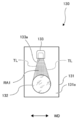
- the optical device to which the technique of the present disclosure is applied is not limited to the above-mentioned endoscope, and may be applied to the surveillance camera 100 as shown in FIG.
- the surveillance camera 100 includes an observation window 102 and a nozzle 103 for supplying air and liquid on the front surface 101a (corresponding to the arrangement surface) of the housing 101.
- a camera (not shown) for taking an image is arranged on the back surface of the observation window 102.
- a part of the region through which the effective luminous flux contributing to imaging passes is the effective region ER.
- a first hydrophobic portion RA1 having a hydrophobic surface property is formed in the region between the tangents TL of the above.
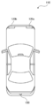
- FIGS. 22 and 23 it may be applied to the headlights 120a and 120b in front of the vehicle 110.
- FIG. 23 shows the headlight 120a on the right front side of the vehicle 110.
- the headlight 120a includes a transparent cover 122 on the front surface of the housing 121.
- a nozzle 123 for supplying air and liquid is provided on the front surface 122a (corresponding to the arrangement surface) of the transparent cover 122.
- An illumination light (not shown) is arranged on the back surface of the transparent cover 122.
- the optical window is an illumination window in which light is emitted from a light source.
- the transparent cover 122 serves as an illumination window.
- the effective area ER On the front surface 122a (corresponding to the arrangement surface) of the transparent cover 122, a part of the area through which the effective light flux contributing to illumination passes is the effective area ER.
- a first hydrophobic portion RA1 having a hydrophobic surface property is formed in the region between the tangents TL of the above.
- the headlight 120a on the right front side and the headlight 120b on the left side front have symmetrical shapes, and the components are the same.
- the back camera 130 includes an observation window 132 and a nozzle 133 for supplying air and liquid on the imaging side surface 131a (corresponding to the arrangement surface) of the housing 131.
- a camera (not shown) for taking an image is arranged on the back surface of the observation window 132.
- the entire area of the observation window 132 is the effective area.
- the area between the observation window 132 and the nozzle 133 which is drawn from each of both ends of the opening 133a in the width direction WD with respect to the observation window 132.
- a first hydrophobic portion RA1 having hydrophobic surface properties is formed in the region between the tangents TL of the book.
- the optical device to which the technique of the present disclosure is applied may be applied to any optical device as long as it is an optical device provided with an optical window and a nozzle for supplying air and liquid.
- the first hydrophobic portion is a part of the arrangement surface existing between the effective region of the optical window and the nozzle, and is an opening in the width direction intersecting the injection direction of the nozzle and along the arrangement surface. It is preferable, but not limited to, the entire area of the recommended hydrophobicization region between the two tangents drawn from each of both ends with respect to the effective region. Even if it is difficult to make the entire area of the recommended hydrophobicization area the first hydrophobic part due to processing restrictions, etc., if 80% or more of the recommended hydrophobicization area is the first hydrophobic part, the residue on the optical window will remain. The effect of facilitating the removal of the liquid can be obtained.
- the recommended hydrophobization region is designated as the first hydrophobic portion, it is easier to remove the residual liquid on the optical window as compared with the case where 80% or more of the region is designated as the first hydrophobic portion. You can get the effect of
- the mode is not limited to the mode in which the first hydrophobic portion and the hydrophilic portion are completely adjacent to each other, and a gap of 1 mm or less may be provided between the first hydrophobic portion and the hydrophilic portion. Even if it is difficult to make the first hydrophobic part and the hydrophilic part completely adjacent to each other due to processing restrictions, etc., if the distance between the first hydrophobic part and the hydrophilic part is 1 mm or less, the first hydrophobic part is sent at the time of water supply. It is possible to easily induce water droplets from the hydrophobic portion to the hydrophilic portion side, and it is possible to prevent the water droplets induced in the hydrophilic portion from flowing back to the first hydrophobic portion.
Landscapes
- Health & Medical Sciences (AREA)
- Life Sciences & Earth Sciences (AREA)
- Physics & Mathematics (AREA)
- Surgery (AREA)
- Optics & Photonics (AREA)
- Medical Informatics (AREA)
- Animal Behavior & Ethology (AREA)
- Radiology & Medical Imaging (AREA)
- Nuclear Medicine, Radiotherapy & Molecular Imaging (AREA)
- Engineering & Computer Science (AREA)
- Biomedical Technology (AREA)
- Heart & Thoracic Surgery (AREA)
- Biophysics (AREA)
- Molecular Biology (AREA)
- Pathology (AREA)
- General Health & Medical Sciences (AREA)
- Public Health (AREA)
- Veterinary Medicine (AREA)
- General Physics & Mathematics (AREA)
- Astronomy & Astrophysics (AREA)
- Chemical & Material Sciences (AREA)
- Chemical Kinetics & Catalysis (AREA)
- Endoscopes (AREA)
- Instruments For Viewing The Inside Of Hollow Bodies (AREA)
Abstract
Description
[内視鏡装置の構成]
図1は本開示の第1実施形態に係る内視鏡を備えた内視鏡装置11の全体構成図を示す図である。図1に示すように、内視鏡装置11は、内視鏡12と、制御装置13と、光源装置14と、送気送水装置15とを備えている。
図2は内視鏡を先端側から見た平面図である。図3は内視鏡の挿入部先端の断面図であり、図2中のA-A線断面図である。
以上の構成の先端部16aを有する内視鏡12において、観察窓52の光入射面52aを洗浄するために、送気・送水を行う際の作用について説明する。
比較例を示す図9において、第1疎水部RA1を設けていない従来の内視鏡の例を示す。この場合において、図9Aに示すように、ノズル27の開口27aから観察窓52に向けて水WFを噴射すると、噴射された水WFは、観察窓52とノズル27との間の領域RNを通過する。図9Bに示すように、領域RNの表面特性が疎水性ではない場合には、噴射した水WFの一部が領域RN上に水滴WGとして残留する量が多い。
第2実施形態の内視鏡12は、第1実施形態の内視鏡12に対して、第1疎水部RA1に加えて第2疎水部RA2を追加し、かつ、親水部RBの範囲を変更したものである。
本開示の技術は、上述の種々の実施形態と種々の変形例を適宜組み合わせることも可能である。また、上記各実施形態に限らず、要旨を逸脱しない限り種々の構成を採用し得ることは勿論である。
Claims (10)
- 光学窓と、
気体および液体が噴射される開口を有し、前記気体および前記液体を選択的に噴射することにより前記光学窓の有効領域を洗浄する送気送液用のノズルと、
前記光学窓と前記ノズルとが配置された配置面と、
前記有効領域と前記ノズルとの間に存在する前記配置面の一部の領域であって、前記ノズルの噴射方向と交差しかつ前記配置面に沿った幅方向における前記開口の両端の各々から前記有効領域に対して引いた2本の接線の間の領域に形成された、疎水性の表面特性を有する第1疎水部とを備える
光学装置。 - 前記有効領域を挟んで前記ノズルの噴射方向の下流側で前記有効領域に隣接する領域に第2疎水部が形成されている
請求項1に記載の光学装置。 - 前記幅方向において、前記2本の接線の外側で、かつ前記第1疎水部に隣接する領域に、親水性の表面特性を有する親水部が形成されている
請求項1または2に記載の光学装置。 - 前記親水部は前記接線に沿って前記有効領域の下流側まで延びている
請求項3に記載の光学装置。 - 前記光学窓のうち少なくとも前記有効領域は疎水性を有する
請求項1から4のいずれか1項に記載の光学装置。 - 前記第1疎水部は、複数の凸部が周期的に配列されている第1微細凹凸構造である
請求項1から5のいずれか1項に記載の光学装置。 - 前記第1微細凹凸構造は、凸部の先端面同士の間隔が0.1μm以上かつ10μm以下である
請求項6に記載の光学装置。 - 前記第1微細凹凸構造は、凸部の高さが2μm以上かつ50μm以下である
請求項6または7に記載の光学装置。 - 前記親水部は、複数の凸部がランダムに配列されている第2微細凹凸構造である
請求項3または4に記載の光学装置。 - 前記第2微細凹凸構造は、表面粗さが0.5μm以上かつ1μm以下である
請求項9に記載の光学装置。
Priority Applications (3)
| Application Number | Priority Date | Filing Date | Title |
|---|---|---|---|
| EP21780769.2A EP4130845A4 (en) | 2020-03-31 | 2021-01-29 | OPTICAL DEVICE |
| JP2022511580A JP7392113B2 (ja) | 2020-03-31 | 2021-01-29 | 光学装置 |
| US17/929,312 US20220409034A1 (en) | 2020-03-31 | 2022-09-02 | Optical device |
Applications Claiming Priority (2)
| Application Number | Priority Date | Filing Date | Title |
|---|---|---|---|
| JP2020-064617 | 2020-03-31 | ||
| JP2020064617 | 2020-03-31 |
Related Child Applications (1)
| Application Number | Title | Priority Date | Filing Date |
|---|---|---|---|
| US17/929,312 Continuation US20220409034A1 (en) | 2020-03-31 | 2022-09-02 | Optical device |
Publications (1)
| Publication Number | Publication Date |
|---|---|
| WO2021199639A1 true WO2021199639A1 (ja) | 2021-10-07 |
Family
ID=77930245
Family Applications (1)
| Application Number | Title | Priority Date | Filing Date |
|---|---|---|---|
| PCT/JP2021/003279 Ceased WO2021199639A1 (ja) | 2020-03-31 | 2021-01-29 | 光学装置 |
Country Status (4)
| Country | Link |
|---|---|
| US (1) | US20220409034A1 (ja) |
| EP (1) | EP4130845A4 (ja) |
| JP (1) | JP7392113B2 (ja) |
| WO (1) | WO2021199639A1 (ja) |
Cited By (1)
| Publication number | Priority date | Publication date | Assignee | Title |
|---|---|---|---|---|
| JP2023094145A (ja) * | 2021-12-23 | 2023-07-05 | ミツミ電機株式会社 | 撮像装置 |
Families Citing this family (2)
| Publication number | Priority date | Publication date | Assignee | Title |
|---|---|---|---|---|
| US20220260757A1 (en) * | 2021-02-16 | 2022-08-18 | Kester Julian Batchelor | Low adhesion surfaces and method for scopes |
| DE102021114984A1 (de) * | 2021-06-10 | 2022-12-15 | Hoya Corporation | Endoskop mit Düsenelement zur Reinigung eines Linsenelementes |
Citations (9)
| Publication number | Priority date | Publication date | Assignee | Title |
|---|---|---|---|---|
| JPH08278456A (ja) * | 1995-04-10 | 1996-10-22 | Toshiba Corp | 内視鏡 |
| JPH10262905A (ja) * | 1997-03-26 | 1998-10-06 | Fuji Photo Optical Co Ltd | 内視鏡 |
| JP2008253634A (ja) * | 2007-04-06 | 2008-10-23 | Olympus Corp | 観察装置 |
| JP2010131120A (ja) * | 2008-12-03 | 2010-06-17 | Fujifilm Corp | 内視鏡 |
| WO2014017405A1 (ja) * | 2012-07-27 | 2014-01-30 | 日産自動車株式会社 | 車載カメラ装置 |
| JP2016022006A (ja) | 2014-07-16 | 2016-02-08 | オリンパス株式会社 | 内視鏡 |
| JP2016187535A (ja) * | 2015-03-30 | 2016-11-04 | 住友ベークライト株式会社 | 内視鏡用フードおよびフード付き内視鏡 |
| JP2017534318A (ja) * | 2014-09-10 | 2017-11-24 | インテュイティブ サージカル オペレーションズ, インコーポレイテッド | 噛み合うカテーテル先端及びツールを用いるデバイス、システム、及び方法 |
| JP2020064617A (ja) | 2018-09-27 | 2020-04-23 | 中強光電股▲ふん▼有限公司 | インテリジェント音声システム及び投影機制御方法 |
Family Cites Families (3)
| Publication number | Priority date | Publication date | Assignee | Title |
|---|---|---|---|---|
| JPH1099260A (ja) * | 1996-09-27 | 1998-04-21 | Olympus Optical Co Ltd | 内視鏡 |
| US8425058B2 (en) * | 2006-11-14 | 2013-04-23 | Alpine Electronics, Inc. | Optical unit, image pickup device using the optical unit, and on-vehicle image display device using the image pickup device |
| JP2015027324A (ja) * | 2013-07-30 | 2015-02-12 | パナソニック株式会社 | 内視鏡 |
-
2021
- 2021-01-29 JP JP2022511580A patent/JP7392113B2/ja active Active
- 2021-01-29 WO PCT/JP2021/003279 patent/WO2021199639A1/ja not_active Ceased
- 2021-01-29 EP EP21780769.2A patent/EP4130845A4/en not_active Withdrawn
-
2022
- 2022-09-02 US US17/929,312 patent/US20220409034A1/en active Pending
Patent Citations (9)
| Publication number | Priority date | Publication date | Assignee | Title |
|---|---|---|---|---|
| JPH08278456A (ja) * | 1995-04-10 | 1996-10-22 | Toshiba Corp | 内視鏡 |
| JPH10262905A (ja) * | 1997-03-26 | 1998-10-06 | Fuji Photo Optical Co Ltd | 内視鏡 |
| JP2008253634A (ja) * | 2007-04-06 | 2008-10-23 | Olympus Corp | 観察装置 |
| JP2010131120A (ja) * | 2008-12-03 | 2010-06-17 | Fujifilm Corp | 内視鏡 |
| WO2014017405A1 (ja) * | 2012-07-27 | 2014-01-30 | 日産自動車株式会社 | 車載カメラ装置 |
| JP2016022006A (ja) | 2014-07-16 | 2016-02-08 | オリンパス株式会社 | 内視鏡 |
| JP2017534318A (ja) * | 2014-09-10 | 2017-11-24 | インテュイティブ サージカル オペレーションズ, インコーポレイテッド | 噛み合うカテーテル先端及びツールを用いるデバイス、システム、及び方法 |
| JP2016187535A (ja) * | 2015-03-30 | 2016-11-04 | 住友ベークライト株式会社 | 内視鏡用フードおよびフード付き内視鏡 |
| JP2020064617A (ja) | 2018-09-27 | 2020-04-23 | 中強光電股▲ふん▼有限公司 | インテリジェント音声システム及び投影機制御方法 |
Non-Patent Citations (1)
| Title |
|---|
| See also references of EP4130845A4 |
Cited By (1)
| Publication number | Priority date | Publication date | Assignee | Title |
|---|---|---|---|---|
| JP2023094145A (ja) * | 2021-12-23 | 2023-07-05 | ミツミ電機株式会社 | 撮像装置 |
Also Published As
| Publication number | Publication date |
|---|---|
| EP4130845A1 (en) | 2023-02-08 |
| US20220409034A1 (en) | 2022-12-29 |
| JPWO2021199639A1 (ja) | 2021-10-07 |
| EP4130845A4 (en) | 2023-09-20 |
| JP7392113B2 (ja) | 2023-12-05 |
Similar Documents
| Publication | Publication Date | Title |
|---|---|---|
| JP5554153B2 (ja) | 内視鏡 | |
| WO2021199639A1 (ja) | 光学装置 | |
| CN102652663B (zh) | 内窥镜 | |
| CN106063697B (zh) | 内窥镜 | |
| JP5433116B1 (ja) | 内視鏡 | |
| JP5331840B2 (ja) | 内視鏡 | |
| JP6050211B2 (ja) | 内視鏡 | |
| JP5380422B2 (ja) | 内視鏡 | |
| JP7439311B2 (ja) | 内視鏡 | |
| JPH01204637A (ja) | 内視鏡 | |
| JP4424795B2 (ja) | 内視鏡の先端部 | |
| JP2002233491A (ja) | 先端キャップを有する内視鏡の先端部 | |
| CN107529946A (zh) | 内窥镜 | |
| JP5297901B2 (ja) | 内視鏡挿入部の先端部構造 | |
| JP4049859B2 (ja) | 内視鏡装置 | |
| JP6151196B2 (ja) | 内視鏡 | |
| JP2011188984A (ja) | 内視鏡アタッチメント | |
| JP6151195B2 (ja) | 内視鏡 | |
| JP5368380B2 (ja) | 内視鏡 | |
| JP6564752B2 (ja) | 内視鏡 | |
| JP2010063773A (ja) | 内視鏡 | |
| JP2019188235A (ja) | 内視鏡 | |
| JP5046792B2 (ja) | 内視鏡の先端部 | |
| JP5722490B2 (ja) | 内視鏡 | |
| JP2013223801A (ja) | 内視鏡 |
Legal Events
| Date | Code | Title | Description |
|---|---|---|---|
| 121 | Ep: the epo has been informed by wipo that ep was designated in this application |
Ref document number: 21780769 Country of ref document: EP Kind code of ref document: A1 |
|
| ENP | Entry into the national phase |
Ref document number: 2022511580 Country of ref document: JP Kind code of ref document: A |
|
| NENP | Non-entry into the national phase |
Ref country code: DE |
|
| ENP | Entry into the national phase |
Ref document number: 2021780769 Country of ref document: EP Effective date: 20221031 |
|
| WWW | Wipo information: withdrawn in national office |
Ref document number: 2021780769 Country of ref document: EP |