WO2021199751A1 - 油分離器 - Google Patents
油分離器 Download PDFInfo
- Publication number
- WO2021199751A1 WO2021199751A1 PCT/JP2021/005844 JP2021005844W WO2021199751A1 WO 2021199751 A1 WO2021199751 A1 WO 2021199751A1 JP 2021005844 W JP2021005844 W JP 2021005844W WO 2021199751 A1 WO2021199751 A1 WO 2021199751A1
- Authority
- WO
- WIPO (PCT)
- Prior art keywords
- wall
- space
- spaces
- oil separator
- oil
- Prior art date
- Legal status (The legal status is an assumption and is not a legal conclusion. Google has not performed a legal analysis and makes no representation as to the accuracy of the status listed.)
- Ceased
Links
Images





Classifications
-
- F—MECHANICAL ENGINEERING; LIGHTING; HEATING; WEAPONS; BLASTING
- F04—POSITIVE - DISPLACEMENT MACHINES FOR LIQUIDS; PUMPS FOR LIQUIDS OR ELASTIC FLUIDS
- F04B—POSITIVE-DISPLACEMENT MACHINES FOR LIQUIDS; PUMPS
- F04B39/00—Component parts, details, or accessories, of pumps or pumping systems specially adapted for elastic fluids, not otherwise provided for in, or of interest apart from, groups F04B25/00 - F04B37/00
- F04B39/02—Lubrication
-
- B—PERFORMING OPERATIONS; TRANSPORTING
- B01—PHYSICAL OR CHEMICAL PROCESSES OR APPARATUS IN GENERAL
- B01D—SEPARATION
- B01D46/00—Filters or filtering processes specially modified for separating dispersed particles from gases or vapours
- B01D46/0002—Casings; Housings; Frame constructions
-
- B—PERFORMING OPERATIONS; TRANSPORTING
- B01—PHYSICAL OR CHEMICAL PROCESSES OR APPARATUS IN GENERAL
- B01D—SEPARATION
- B01D17/00—Separation of liquids, not provided for elsewhere, e.g. by thermal diffusion
- B01D17/02—Separation of non-miscible liquids
-
- B—PERFORMING OPERATIONS; TRANSPORTING
- B01—PHYSICAL OR CHEMICAL PROCESSES OR APPARATUS IN GENERAL
- B01D—SEPARATION
- B01D45/00—Separating dispersed particles from gases or vapours by gravity, inertia, or centrifugal forces
- B01D45/12—Separating dispersed particles from gases or vapours by gravity, inertia, or centrifugal forces by centrifugal forces
- B01D45/16—Separating dispersed particles from gases or vapours by gravity, inertia, or centrifugal forces by centrifugal forces generated by the winding course of the gas stream, the centrifugal forces being generated solely or partly by mechanical means, e.g. fixed swirl vanes
-
- B—PERFORMING OPERATIONS; TRANSPORTING
- B01—PHYSICAL OR CHEMICAL PROCESSES OR APPARATUS IN GENERAL
- B01D—SEPARATION
- B01D46/00—Filters or filtering processes specially modified for separating dispersed particles from gases or vapours
- B01D46/0039—Filters or filtering processes specially modified for separating dispersed particles from gases or vapours with flow guiding by feed or discharge devices
-
- F—MECHANICAL ENGINEERING; LIGHTING; HEATING; WEAPONS; BLASTING
- F04—POSITIVE - DISPLACEMENT MACHINES FOR LIQUIDS; PUMPS FOR LIQUIDS OR ELASTIC FLUIDS
- F04B—POSITIVE-DISPLACEMENT MACHINES FOR LIQUIDS; PUMPS
- F04B39/00—Component parts, details, or accessories, of pumps or pumping systems specially adapted for elastic fluids, not otherwise provided for in, or of interest apart from, groups F04B25/00 - F04B37/00
- F04B39/02—Lubrication
- F04B39/0223—Lubrication characterised by the compressor type
-
- F—MECHANICAL ENGINEERING; LIGHTING; HEATING; WEAPONS; BLASTING
- F04—POSITIVE - DISPLACEMENT MACHINES FOR LIQUIDS; PUMPS FOR LIQUIDS OR ELASTIC FLUIDS
- F04B—POSITIVE-DISPLACEMENT MACHINES FOR LIQUIDS; PUMPS
- F04B39/00—Component parts, details, or accessories, of pumps or pumping systems specially adapted for elastic fluids, not otherwise provided for in, or of interest apart from, groups F04B25/00 - F04B37/00
- F04B39/02—Lubrication
- F04B39/0284—Constructional details, e.g. reservoirs in the casing
-
- F—MECHANICAL ENGINEERING; LIGHTING; HEATING; WEAPONS; BLASTING
- F04—POSITIVE - DISPLACEMENT MACHINES FOR LIQUIDS; PUMPS FOR LIQUIDS OR ELASTIC FLUIDS
- F04B—POSITIVE-DISPLACEMENT MACHINES FOR LIQUIDS; PUMPS
- F04B39/00—Component parts, details, or accessories, of pumps or pumping systems specially adapted for elastic fluids, not otherwise provided for in, or of interest apart from, groups F04B25/00 - F04B37/00
- F04B39/04—Measures to avoid lubricant contaminating the pumped fluid
-
- F—MECHANICAL ENGINEERING; LIGHTING; HEATING; WEAPONS; BLASTING
- F04—POSITIVE - DISPLACEMENT MACHINES FOR LIQUIDS; PUMPS FOR LIQUIDS OR ELASTIC FLUIDS
- F04B—POSITIVE-DISPLACEMENT MACHINES FOR LIQUIDS; PUMPS
- F04B39/00—Component parts, details, or accessories, of pumps or pumping systems specially adapted for elastic fluids, not otherwise provided for in, or of interest apart from, groups F04B25/00 - F04B37/00
- F04B39/12—Casings; Cylinders; Cylinder heads; Fluid connections
- F04B39/121—Casings
-
- F—MECHANICAL ENGINEERING; LIGHTING; HEATING; WEAPONS; BLASTING
- F04—POSITIVE - DISPLACEMENT MACHINES FOR LIQUIDS; PUMPS FOR LIQUIDS OR ELASTIC FLUIDS
- F04B—POSITIVE-DISPLACEMENT MACHINES FOR LIQUIDS; PUMPS
- F04B39/00—Component parts, details, or accessories, of pumps or pumping systems specially adapted for elastic fluids, not otherwise provided for in, or of interest apart from, groups F04B25/00 - F04B37/00
- F04B39/16—Filtration; Moisture separation
-
- F—MECHANICAL ENGINEERING; LIGHTING; HEATING; WEAPONS; BLASTING
- F04—POSITIVE - DISPLACEMENT MACHINES FOR LIQUIDS; PUMPS FOR LIQUIDS OR ELASTIC FLUIDS
- F04C—ROTARY-PISTON, OR OSCILLATING-PISTON, POSITIVE-DISPLACEMENT MACHINES FOR LIQUIDS; ROTARY-PISTON, OR OSCILLATING-PISTON, POSITIVE-DISPLACEMENT PUMPS
- F04C18/00—Rotary-piston pumps specially adapted for elastic fluids
- F04C18/48—Rotary-piston pumps with non-parallel axes of movement of co-operating members
- F04C18/50—Rotary-piston pumps with non-parallel axes of movement of co-operating members the axes being arranged at an angle of 90 degrees
- F04C18/52—Rotary-piston pumps with non-parallel axes of movement of co-operating members the axes being arranged at an angle of 90 degrees of intermeshing engagement type, i.e. with engagement of co-operating members similar to that of toothed gearing
-
- F—MECHANICAL ENGINEERING; LIGHTING; HEATING; WEAPONS; BLASTING
- F04—POSITIVE - DISPLACEMENT MACHINES FOR LIQUIDS; PUMPS FOR LIQUIDS OR ELASTIC FLUIDS
- F04C—ROTARY-PISTON, OR OSCILLATING-PISTON, POSITIVE-DISPLACEMENT MACHINES FOR LIQUIDS; ROTARY-PISTON, OR OSCILLATING-PISTON, POSITIVE-DISPLACEMENT PUMPS
- F04C29/00—Component parts, details or accessories of pumps or pumping installations, not provided for in groups F04C18/00 - F04C28/00
- F04C29/02—Lubrication; Lubricant separation
- F04C29/026—Lubricant separation
-
- F—MECHANICAL ENGINEERING; LIGHTING; HEATING; WEAPONS; BLASTING
- F04—POSITIVE - DISPLACEMENT MACHINES FOR LIQUIDS; PUMPS FOR LIQUIDS OR ELASTIC FLUIDS
- F04C—ROTARY-PISTON, OR OSCILLATING-PISTON, POSITIVE-DISPLACEMENT MACHINES FOR LIQUIDS; ROTARY-PISTON, OR OSCILLATING-PISTON, POSITIVE-DISPLACEMENT PUMPS
- F04C18/00—Rotary-piston pumps specially adapted for elastic fluids
- F04C18/08—Rotary-piston pumps specially adapted for elastic fluids of intermeshing-engagement type, i.e. with engagement of co-operating members similar to that of toothed gearing
- F04C18/12—Rotary-piston pumps specially adapted for elastic fluids of intermeshing-engagement type, i.e. with engagement of co-operating members similar to that of toothed gearing of other than internal-axis type
- F04C18/14—Rotary-piston pumps specially adapted for elastic fluids of intermeshing-engagement type, i.e. with engagement of co-operating members similar to that of toothed gearing of other than internal-axis type with toothed rotary pistons
- F04C18/16—Rotary-piston pumps specially adapted for elastic fluids of intermeshing-engagement type, i.e. with engagement of co-operating members similar to that of toothed gearing of other than internal-axis type with toothed rotary pistons with helical teeth, e.g. chevron-shaped, screw type
-
- F—MECHANICAL ENGINEERING; LIGHTING; HEATING; WEAPONS; BLASTING
- F04—POSITIVE - DISPLACEMENT MACHINES FOR LIQUIDS; PUMPS FOR LIQUIDS OR ELASTIC FLUIDS
- F04C—ROTARY-PISTON, OR OSCILLATING-PISTON, POSITIVE-DISPLACEMENT MACHINES FOR LIQUIDS; ROTARY-PISTON, OR OSCILLATING-PISTON, POSITIVE-DISPLACEMENT PUMPS
- F04C29/00—Component parts, details or accessories of pumps or pumping installations, not provided for in groups F04C18/00 - F04C28/00
- F04C29/06—Silencing
Definitions
- This disclosure relates to an oil separator.
- Patent Document 1 discloses an oil separator attached to a compressor.
- the oil separator has a cover that is attached to the opening of the compressor casing. Inside the cover portion, an internal space communicating with the space on the discharge side of the compressor is formed (see FIG. 3 of Patent Document 1).
- the purpose of the present disclosure is to suppress the vibration of the oil separator due to the acoustic resonance of the internal space of the cover portion.
- the first aspect is A cover (31) attached to the discharge side opening (11a) of the compressor (10), A discharge flow path (38) formed inside the cover portion (31) and It is provided with an oil separation unit (50) that separates oil from the fluid flowing out of the discharge flow path (38). Inside the cover portion (31), an oil separator is provided with a partition wall portion (37) that partitions the internal space (36) facing the opening (11a) into a plurality of spaces (S).
- the partition wall portion (37) partitions the internal space (36) of the cover portion (31) into a plurality of spaces (S).
- the size of each space (S) becomes smaller than the size of one conventional internal space.
- the acoustic resonance frequency in each space (S) can be increased, and the vibration of the oil separator can be suppressed.
- the second aspect is, in the first aspect,
- the internal space (36) has a shape extending in the first direction.
- the partition wall portion (37) includes a first wall (37a, 37b) extending in the first direction and partitioning the internal space (36) in a second direction orthogonal to the first direction.
- the oil separator is likely to be vibrated in the second direction orthogonal to the first direction. Since the partition wall portion (37) of the second aspect partitions the internal space (36) in the second direction, the distance between the plurality of spaces (S) in the second direction can be narrowed. As a result, the acoustic resonance frequency in the second direction can be increased, so that the oil separator can be suppressed from being vibrated in the second direction.
- the third aspect is, in the second aspect,
- the internal space (36) has a shape extending in the vertical direction, which is the first direction.
- the first wall (37a, 37b) extends in the vertical direction and partitions the internal space (36) in the horizontal direction, which is the second direction.
- the oil separator is likely to be vibrated in the horizontal direction orthogonal to the vertical direction. Since the partition wall portion (37) of the third aspect partitions the internal space (36) in the horizontal direction, the horizontal distance between the plurality of spaces (S) can be narrowed. As a result, the acoustic resonance frequency in the horizontal direction can be increased, so that the oil separator can be suppressed from being vibrated in the horizontal direction.
- the fourth aspect is in any one of the first to third aspects.
- the plurality of spaces (S) include at least two spaces (S) having different shapes from each other.
- the resonance mode of these spaces will be excited and the exciting force of the oil separator will increase.
- the excitation of the resonance mode of these spaces (S) can be suppressed because the shapes of at least two spaces (S) are different.
- the fifth aspect is, in the fourth aspect,
- the at least two spaces (S) having different shapes have different heights from each other.
- the excitation of the resonance mode in the height direction of at least two spaces (S) can be suppressed.
- At least two spaces (S) having different shapes from each other have different horizontal widths from each other.
- the excitation of the resonance mode in the width direction of at least two spaces (S) can be suppressed.
- the seventh aspect is, in any one of the fourth to sixth aspects,
- the at least two spaces (S) having different shapes differ from each other in the horizontal depth length.
- the excitation of the resonance mode in the depth direction of at least two spaces (S) can be suppressed.
- the eighth aspect is in any one of the fourth to sixth aspects. All of the plurality of spaces (S) have the same horizontal depth length.
- the structure of the oil separator can be simplified by making the lengths of the depths in the plurality of spaces (S) equal.
- FIG. 1 is a vertical cross-sectional view showing a schematic configuration of a compressor unit according to an embodiment.
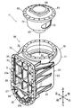
- FIG. 2 is an exploded perspective view of the oil separator.
- FIG. 2 shows a state in which the cover portion is viewed from the front side.
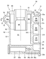
- FIG. 3 is a cross-sectional view taken along the line III-III of FIG.
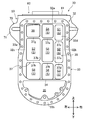
- FIG. 4 is a top view of the oil separator according to the embodiment.
- FIG. 5 is a sectional view taken along line VV of FIG.
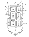
- FIG. 6 is a front view of the cover portion.
- FIG. 7 is a schematic view defining the dimensions of the space.
- FIG. 8 is a table showing an example of dimensions in a plurality of divided spaces.
- FIG. 9 is a diagram corresponding to FIG. 6 according to a modified example.
- the compressor unit (U) includes a compressor (10) and an oil separator (30).
- the oil separator (30) is attached to the compressor (10).
- the compressor unit (U) is connected to the refrigerant circuit of the refrigerating device.
- the refrigerant circuit is filled with refrigerant.
- the refrigerant corresponds to the fluid of the present disclosure.
- the refrigerant circuit performs a vapor compression refrigeration cycle. Specifically, the refrigerant compressed by the compressor dissipates heat by the radiator. The heat-dissipated refrigerant is decompressed by the decompression unit. The refrigerant decompressed in the decompression section evaporates in the evaporator. The refrigerant vaporized by the evaporator is sucked into the compressor.
- the refrigerant contains lubricating oil (hereinafter referred to as oil) that lubricates the sliding portion of the compressor (10).
- the compressor (10) compresses the refrigerant.
- the compressor (10) sucks in a low-pressure gas refrigerant and compresses the gas refrigerant.
- the compressor (10) discharges a high-pressure gas refrigerant after compression.
- the compressor (10) is a screw compressor.
- the compressor (10) is a single screw type having one screw rotor (22).
- the compressor (10) is a one-gate type having one gate rotor (23).
- the compressor (10) includes a casing (11), a motor (15), a drive shaft (18), and a compression mechanism (20).
- the casing (11) is formed in a horizontally long cylindrical shape.
- a low pressure chamber (L) and a high pressure chamber (H) are formed inside the casing (11).
- the low-pressure chamber (L) constitutes a flow path through which the low-pressure gas refrigerant sucked into the compression mechanism (20) flows.
- the high-pressure chamber (H) constitutes a flow path through which the high-pressure gas refrigerant discharged from the compression mechanism (20) flows.
- a suction cover (12) is attached to one end of the casing (11) in the longitudinal direction.
- An opening (11a) is formed at the other end of the casing (11) in the longitudinal direction.
- the opening (11a) is provided on the high-pressure side of the casing (11) where the high-pressure chamber (H) is formed.
- the cover portion (31) of the oil separator (30) is attached to the opening (11a).
- An oil chamber (14) for storing oil is formed at the bottom of the casing (11).
- the motor (15) is housed in the casing (11).
- the motor (15) has a stator (16) and a rotor (17).
- the stator (16) is fixed to the inner wall of the casing (11).
- the rotor (17) is arranged inside the stator (16).
- the drive shaft (18) is fixed inside the rotor (17).
- the drive shaft (18) connects the motor (15) and the compression mechanism (20).
- the drive shaft (18) extends along the longitudinal direction of the casing (11).
- the drive shaft (18) extends substantially horizontally.
- the drive shaft (18) is rotatably supported by a plurality of bearings (19).
- the bearing (19) is fixed to the casing (11) via a bearing folder (not shown).
- the compression mechanism (20) has one cylinder portion (21), one screw rotor (22), and one gate rotor (23).
- the cylinder portion (21) is formed inside the casing (11).
- the screw rotor (22) is arranged inside the cylinder portion (21).
- the screw rotor (22) is fixed to the drive shaft (18).
- a plurality of spiral (three in this example) screw grooves (24) are formed on the outer peripheral surface of the screw rotor (22).
- the outer peripheral surface of the tooth tip of the screw rotor (22) is surrounded by the cylinder portion (21).
- One end side of the screw rotor (22) in the axial direction faces the low pressure chamber (L).
- the other end of the screw rotor (22) in the axial direction faces the high pressure chamber (H).
- the gate rotor (23) is housed in the gate rotor chamber (25).
- the gate rotor (23) has a plurality of gates (23a) arranged radially.
- the gate (23a) of the gate rotor (23) penetrates a part of the cylinder portion (21) and meshes with the screw groove (24).
- a suction port and a compression chamber are formed in the compression mechanism (20).
- the suction port is a portion of the screw groove (24) that opens into the low pressure chamber (L).
- the compression chamber is formed between the inner peripheral surface of the cylinder portion (21), the screw groove (24), and the gate (23a).
- the refrigerant compressed in the compression chamber is discharged to the high pressure chamber (H) through the discharge port.
- the compression mechanism (20) has a slide valve mechanism (not shown).
- the slide valve mechanism adjusts the timing of communicating the compression chamber and the discharge port.
- the slide valve mechanism includes a slide member (slide valve) that moves back and forth along the axial direction of the drive shaft (18). A part of the slide member is located in the high pressure chamber (H).
- the oil separator (30) is a centrifugal type that separates oil from the refrigerant by centrifugal force.
- the oil separator (30) separates oil from the refrigerant discharged from the compression mechanism (20).
- the oil separator (30) includes a cover portion (31), a cylindrical oil separator main body (50), and a bent pipe (70).
- the cover portion (31) is attached to the opening (11a) on the discharge side of the compressor (10).
- the cover portion (31) closes the high pressure chamber (H) of the compressor (10).
- the vertical height of the cover portion (31) is larger than the horizontal width.
- the cover portion (31) has a cover main body (32) and a flange portion (33).
- the cover body (32) is formed in a hollow shape with the front side open.
- the flange portion (33) is provided at the front end of the cover body (32).
- the flange portion (33) is formed in a vertically long frame shape in the vertical direction.
- the flange portion (33) is fixed to the opening (11a) of the casing (11) via a fastening member.
- the flange portion (33) includes a first flange portion (33a) and a second flange portion (33b).
- the first flange portion (33a) is formed from the upper portion to the intermediate portion of the flange portion (33).
- the second flange portion (33b) is formed below the flange portion (33).
- the first flange portion (33a) is formed in an inverted U shape when viewed from the front. Strictly speaking, the first flange portion (33a) has a shape in which the lower side of the vertically long rectangular portion is cut off when viewed from the front.
- the second flange portion (33b) is formed in a U shape when viewed from the front. Strictly speaking, the second flange portion (33b) is formed in an arc shape when viewed from the front.
- the cover part (31) has a partition wall (34).
- the partition wall (34) is provided below the flange portion (33).
- the partition wall (34) is located at the boundary between the first flange portion (33a) and the second flange portion (33b).
- the partition wall (34) extends horizontally so as to extend across the left and right ends of the flange portion (33).
- the partition wall (34) divides the inside of the cover portion (31) into an oil reservoir space (35) and a discharge space (36).
- the oil reservoir space (35) is located below the partition wall (34).
- the oil reservoir space (35) is located inside the second flange portion (33b). As shown in FIG. 1, the oil reservoir space (35) is at a height position corresponding to the oil chamber (14) in the casing (11). The oil separated by the oil separator (30) is collected in the oil reservoir space (35).
- the discharge space (36) is located above the partition wall (34).
- the discharge space (36) is located inside the first flange portion (33a).
- the discharge space (36) is at a height position corresponding to the high pressure chamber (H) in the casing (11).
- the high-pressure gas refrigerant discharged by the compression mechanism (20) flows into the discharge space (36).
- the discharge space (36) corresponds to the internal space of the present disclosure.
- the discharge space (36) is divided into a plurality of spaces by the partition wall portion (37).
- a total of nine spaces of 3 rows ⁇ 3 columns are formed in the cover portion (31) of the present embodiment.
- the uppermost and leftmost space constitutes the discharge flow path (38).
- the discharge flow path (38) communicates with the curved pipe (70).
- the remaining eight spaces correspond to the divided spaces (S).
- the divided space (S) corresponds to the space of the present disclosure. Details of the partition wall portion (37) and the divided space (S) will be described later.
- the oil separator main body (50) will be described with reference to FIGS. 2 to 5.
- the oil separator body (50) is formed in a cylindrical shape. Strictly speaking, the oil separator body (50) is formed in a hollow cylindrical shape. A separation space (51) for separating oil from the refrigerant by centrifugal force is formed inside the oil separator main body (50). The refrigerant flowing through the bent pipe (70) flows into the separation space (51).
- the oil separator main body (50) has an outer cylinder (52) and a lid member (60).
- the oil separator body (50) corresponds to the oil separator of the present disclosure.
- the outer cylinder (52) is formed in the shape of a bottomed cylinder with the upper side downward.
- the outer cylinder (52) includes a tubular body portion (53) and a bottom portion (54) formed below the body portion (53). Strictly speaking, the outer cylinder (52) has an outer wall portion (71) of a curved pipe (70).
- the front part of the body part (53) is formed integrally with the cover part (31).
- An oil spill hole (55) is formed in the body portion (53).
- the oil spill hole (55) is formed at the lower end of the front portion of the body portion (53).
- the oil spill hole (55) is located at the same height as the bottom surface of the outer cylinder (52).
- the oil spill hole (55) communicates the separation space (51) and the oil reservoir space (35).
- the oil in the separation space (51) flows out into the oil reservoir space (35) through the oil spill hole (55).
- the oil return flow path (56) is a flow path for supplying the oil in the oil reservoir space (35) to a predetermined lubricating portion of the compressor (10).
- the oil return flow path (56) includes a first flow path (56a), a second flow path (56b), and a third flow path (56c). In the oil return flow path (56), the first flow path (56a), the second flow path (56b), and the third flow path (56c) are connected in order from the upstream side to the downstream side.
- the inflow end of the first flow path (56a) opens into the oil reservoir space (35).
- the outflow end of the first flow path (56a) opens into the second flow path (56b).
- the outer diameter of the second flow path (56b) is larger than the outer diameter of the first flow path (56a) and the third flow path (56c).
- the second flow path (56b) is provided with a trapping member (57) that traps impurities in the oil.
- the catching member (57) is composed of, for example, a bottomed cylindrical mesh member.
- the front opening end of the capture member (57) surrounds the inflow port of the third flow path (56c).
- the oil in which impurities are trapped by the trapping member (57) is supplied to a predetermined sliding portion via the third flow path (56c).
- the lid member (60) is attached to the upper open portion of the outer cylinder (52).
- the lid member (60) has an upper lid (61) and an inner cylinder (62).
- the lid member (60) of the present embodiment further includes an inner wall portion (72) of the bent pipe (70).
- the inner wall portion (72) forms a part of the curved pipe (70).
- the upper lid (61) is formed in a substantially disk shape.
- the upper lid (61) is fixed to the upper end of the outer cylinder (52) via a fastening member.
- a seal member (not shown) is provided between the lower surface of the outer edge of the upper lid (61) and the upper end surface of the outer cylinder (52).
- the inner cylinder (62) is formed in a cylindrical shape with the top and bottom open.
- the inner cylinder (62) is provided in the central portion of the upper lid (61).
- the inner cylinder (62) projects downward from the upper lid (61).
- the inner cylinder (62) is at a height position corresponding to the upper part of the outer cylinder (52). In other words, the inner cylinder (62) is at a height position corresponding to approximately half of the upper side of the outer cylinder (52).
- a cylindrical space (63) is formed between the outer cylinder (52) and the inner cylinder (62).
- the cylindrical space (63) forms part of the separation space (51). In the cylindrical space (63), a swirling flow of the refrigerant is particularly likely to be formed.
- an outflow path (64) is formed to communicate the separation space (51) and the discharge pipe (not shown).
- the discharge pipe is connected to the refrigerant circuit.
- the bent pipe (70) will be described with reference to FIGS. 2 to 5.
- the bent pipe (70) introduces a high-pressure refrigerant containing oil into the oil separator body (50).
- the bent pipe (70) is arranged so as to surround the body portion (53) of the oil separator main body (50) in the circumferential direction.
- the curved pipe (70) has the same height position throughout. In other words, the bent pipe (70) of the present embodiment is not inclined in the vertical direction.
- the curved pipe (70) curves in the direction along the swirling flow. In FIG. 5, the direction of the swirling flow is represented by the arrow R of the alternate long and short dash line.
- the bent tube (70) is at a height position corresponding to the cylindrical space (63). Inside the curved pipe (70), an internal flow path (70a) curved along the curved pipe (70) is formed.
- the bent pipe (70) includes an outer wall portion (71) and an inner wall portion (72).
- the outer wall part (71) extends along the circumferential direction of the body part (53).
- the outer wall portion (71) bulges outward from the body portion (53) in the radial direction of the body portion (53).
- the inner surface of the outer wall portion (71) facing the inner flow path (70a) is formed in a substantially U shape with the front side open when viewed from the A cross section.
- the A cross section is a cross section perpendicular to the pipe axis direction of the bent pipe (70).
- the A cross section is a cross section perpendicular to the paper surface direction of FIG.
- the outer wall part (71) and the body part (53) are integrally configured.
- the outer wall portion (71) is integrally formed on the upper portion of the body portion (53).
- the lid member (60) is not attached to the outer cylinder (52)
- the inner surface of the outer wall portion (71) faces the inside of the outer cylinder (52).
- the inner wall part (72) extends along the outer wall part (71).
- the inner wall portion (72) closes the radial inner open portion of the outer wall portion (71).
- the inner surface of the inner wall portion (72) facing the inner flow path (70a) is formed in a plane extending vertically in the cross-sectional view of A.
- the outer wall portion (71) and the inner wall portion (72) are composed of separate members.
- the inner wall portion (72) and the upper lid (61) are integrally formed. More specifically, the inner wall portion (72), the upper lid (61), and the inner cylinder (62) are integrally formed.
- the inner wall portion (72) extends downward from the portion of the upper lid (61) near the outer edge.
- the inflow end of the bent pipe (70) communicates with the discharge flow path (38) of the flange portion (33).
- An outlet (73) is formed on the inner wall portion (72).
- the outlet (73) is located corresponding to the outflow end of the curved pipe (70).
- the outlet (73) corresponds to a hole in the present disclosure.
- the oil separator (30) is mainly composed of a first member and a second member.
- the first member includes a cover portion (31), a body portion (53), a bottom portion (54), and an outer wall portion (71).
- the first member is composed of a casting molded by a mold.
- the second member includes an upper lid (61), an inner cylinder (62), and an inner wall portion (72).
- the second member is composed of a casting molded by a mold.
- the refrigerant is periodically discharged from the compression mechanism (20) to the high pressure chamber (H).
- the refrigerant discharged to the high pressure chamber (H) is sent to the high pressure space (S) in the flange portion (33) and flows into the bent pipe (70) through the discharge flow path (38).
- the curved pipe (70) is curved so as to surround the body portion (53) in the circumferential direction. Therefore, centrifugal force acts on the oil contained in the refrigerant flowing through the internal flow path (70a). As a result, the oil is separated from the refrigerant.
- the oil separated from the refrigerant moves on the inner surface of the outer wall portion (71). Separated fine oils aggregate on the inner surface of the outer wall portion (71).
- the bent pipe (70) is located radially outward from the outer cylinder (52). Therefore, in the internal flow path (70a) of the bent pipe (70), the centrifugal force acting on the oil is larger than that in the separation space (51). Thereby, in the bent pipe (70), the oil separation effect can be promoted.
- the refrigerant and oil flowing out of the bent pipe (70) flow into the separation space (51) in the outer cylinder (52) through the outlet (73).
- the oil aggregated in the curved pipe (70) collects at the bottom of the separation space (51).
- the fine oil remaining in the refrigerant is separated from the refrigerant by centrifugal force in the separation space (51).
- the refrigerant from which the refrigerant has been separated as described above flows out to the discharge pipe via the outflow passage (64) of the inner cylinder (62).
- the refrigerant flowing out of the discharge pipe flows through the refrigerant circuit and is used in the refrigeration cycle.
- the cover body (32) has an upper wall (32a), a first side wall (32b), a second side wall (32c), and a third side wall (32d).
- the first side wall (32b) constitutes the wall on the right side of the cover body (32).
- the second side wall (32c) constitutes the left wall of the cover body (32).
- the third side wall (32d) constitutes the rear wall of the cover body (32).
- the first side wall (32b), the second side wall (32c), and the third side wall (32d) extend in the vertical direction.
- the upper wall (32a) constitutes the upper wall of the cover body (32).
- the upper wall (32a) extends horizontally.
- a discharge space (36) is formed between the first side wall (32b), the second side wall (32c), the third side wall (32d), the upper wall (32a), and the partition wall (34).
- the discharge space (36) extends in the vertical direction.
- the vertical direction corresponds to the first direction of the present disclosure.
- the discharge space (36) is divided into a plurality of divided spaces (S) by the partition wall portion (37).
- the partition wall portion (37) includes a first vertical wall (37a), a second vertical wall (37b), a first horizontal wall (37c), a second horizontal wall (37d), a third horizontal wall (37e), and a fourth horizontal wall (37f). , 5th lateral wall (37g), 6th lateral wall (37h) is included.
- the first vertical wall (37a) and the second vertical wall (37b) extend in the vertical direction.
- the first vertical wall (37a) and the second vertical wall (37b) partition the discharge space (36) in the left-right direction.
- the left-right direction corresponds to the second direction of the present disclosure, which is orthogonal to the first direction.
- the first vertical wall (37a) is closer to the first side wall (32b) than the second side wall (32c).
- the second vertical wall (37b) is closer to the second side wall (32c) than the first side wall (32b).
- the first vertical wall (37a) and the second vertical wall (37b) correspond to the first wall of the present disclosure.
- the first side wall (37c), the second side wall (37d), the third side wall (37e), the fourth side wall (37f), the fifth side wall (37g), and the sixth side wall (37h) extend in the horizontal direction. ..
- the first side wall (37c), the second side wall (37d), the third side wall (37e), the fourth side wall (37f), the fifth side wall (37g), and the sixth side wall (37h) have a discharge space (36). It is partitioned in the vertical direction.
- a first horizontal wall (37c) and a second horizontal wall (37d) are provided between the first side wall (32b) and the first vertical wall (37a).
- the first lateral wall (37c) is located above the second lateral wall (37d).
- a third horizontal wall (37e) and a fourth horizontal wall (37f) are provided between the first vertical wall (37a) and the second vertical wall (37b).
- the third lateral wall (37e) is located above the fourth lateral wall (37f).
- a fifth horizontal wall (37g) and a sixth horizontal wall (37h) are provided between the second vertical wall (37b) and the second side wall (32c).
- the fifth lateral wall (37 g) is located above the sixth lateral wall (37 h).
- a first divided space (S1) is formed between the first side wall (32b), the first vertical wall (37a), the upper wall (32a), and the first horizontal wall (37c).
- a second divided space (S2) is formed between the first side wall (32b), the first vertical wall (37a), the first horizontal wall (37c), and the second horizontal wall (37d).
- a third divided space (S3) is formed between the first side wall (32b), the first vertical wall (37a), the second horizontal wall (37d), and the partition wall (34).
- a fourth divided space (S4) is formed between the first vertical wall (37a), the second vertical wall (37b), the upper wall (32a), and the third horizontal wall (37e).
- a fifth divided space (S5) is formed between the first vertical wall (37a), the second vertical wall (37b), the third horizontal wall (37e), and the fourth horizontal wall (37f).
- a sixth divided space (S6) is formed between the first vertical wall (37a), the second vertical wall (37b), the fourth horizontal wall (37f), and the partition wall (34).
- the discharge flow path (38) described above is formed between the second vertical wall (37b), the second side wall (32c), the upper wall (32a), and the fifth horizontal wall (37g).
- a seventh divided space (S7) is formed between the second vertical wall (37b), the second side wall (32c), the fifth horizontal wall (37g), and the sixth horizontal wall (37h).
- An eighth divided space (S8) is formed between the second vertical wall (37b), the second side wall (32c), the sixth horizontal wall (37h), and the partition wall (34).
- the seventh divided space (S7) overlaps the above-mentioned slide member in the advancing / retreating direction of the slide member.
- the direction of the slide member corresponds to the front-rear direction of the cover portion (31). Therefore, when the slide member moves rearward, the rear portion of the slide member is located inside the seventh division space (S7). Therefore, the slide member and the cover portion (31) do not interfere with each other.
- the discharge space (36) functions as a space for suppressing interference between the parts of the compressor (10) and the cover portion (31).
- a notch for suppressing interference with the rear end of the slide member may be formed on the inner wall of the seventh divided space (S).
- first to eighth divided spaces may be referred to as divided spaces (S) for convenience.
- These divided spaces (S) are formed in a substantially rectangular parallelepiped shape.
- the shapes of all the divided spaces (S) among the plurality of (8) divided spaces (S) are different.
- the height H indicates the length of the divided space (S) in the vertical direction.
- the width W indicates the length of the divided space (S) in the left-right direction.
- the depth length D indicates the depth length of the divided space (S) in the front-rear direction.
- the heights H of all the divided spaces (S) are different from each other.
- the widths W of the three divided spaces (S) arranged vertically are equal to each other.
- the widths W of the first to third divided spaces (S1 to S3) are equal to each other.
- the widths W of the fourth to sixth divided spaces (S4 to S6) are equal to each other.
- the widths W of the 7th and 8th division spaces (S8) are equal to each other.
- the width W of the first to third divided spaces (S1 to S3), the width W of the fourth to sixth divided spaces (S4 to S6), and the width W of the seventh and eighth divided spaces (S8) are Different from each other.
- the widths W of at least three divided spaces (S) are different.
- the widths of the divided spaces (S) partitioned in the second direction are different from each other.
- the depth lengths D of all the divided spaces (S) are equal to each other.
- the discharge space (36) is one space
- the acoustic resonance frequency of the discharge space (36) tends to be low due to the discharge pulsation of the compression mechanism (20). Therefore, the oil separator (30) and the compressor (10) are vibrated, and the vibration and noise of the compressor unit (U) increase.
- the acoustic resonance frequency in each divided space (S) can be increased. As a result, it is possible to suppress the vibration of the oil separator (30) due to the discharge pulsation, and it is possible to suppress the vibration of the compressor unit (U) and the increase in noise.
- the cover portion (31) in which the discharge space (36) extends in the vertical direction is easily vibrated in the width direction due to the discharge pulsation.
- the discharge space (36) is partitioned in the left-right direction by vertical walls (37a, 37b) extending in the vertical direction.
- the width of the divided space (S) can be shortened, so that the acoustic resonance frequency in the width direction in the divided space (S) can be increased.
- the vertical walls (37a, 37b) extend linearly in the vertical direction, so processing is easy.
- the vertical walls (37a, 37b) can increase the rigidity of the cover portion (31) in the longitudinal direction.
- the lateral walls (37c, 37d, 37e, 37f) the rigidity of the cover portion (31) in the left-right direction can be increased.
- the resonance mode of these divided spaces (S) is excited, and the exciting force of the oil separator (30) increases.
- the excitation of the resonance mode of these divided spaces (S) can be suppressed.
- the shapes of all the divided spaces (S) are different from each other. Therefore, the excitation in the resonance mode can be sufficiently suppressed.
- the widths W of the plurality of divided spaces (S) are different from each other. Therefore, it is possible to suppress the excitation of the resonance mode in the width direction, which tends to cause the oil separator (30) to shake.
- the heights H of the plurality of divided spaces (S) are different from each other. Therefore, the excitation of the resonance mode in the height direction can be suppressed.
- the depth and length D of the plurality of divided spaces (S) are equal to each other. Therefore, the inner surface of the third side wall (32d) can be formed flat, and the structure of the cover portion (31) can be simplified.
- the third side wall (32d) has the largest area of the walls forming the cover portion (31). By flattening the third side wall (32d), the mold for molding the cover portion (31) can be effectively simplified.
- the resonance point of each divided space (S) can be easily adjusted based on the two parameters of the width W and the height H of each divided space (S). can. As a result, the excitation of the resonance mode can be suppressed in each divided space (S).
- the overall depth length of the discharge space (36) is shorter than the overall height and overall width of the discharge space (36). Therefore, even if the depth lengths D of the plurality of divided spaces (S) are set to different lengths, the effect of suppressing the exciting force of the oil separator (30) is low. Conversely, the overall height and width of the discharge space (36) is longer than the overall depth length of the discharge space (36). Therefore, by setting the heights H of the plurality of divided spaces (S) to different lengths, the exciting force of the oil separator (30) can be effectively suppressed. By setting the widths W of the plurality of divided spaces (S) to different lengths, the exciting force of the oil separator (30) can be effectively suppressed.
- the partition wall portion (37) of the cover portion (31) includes a first vertical wall (37a), a first horizontal wall (37c), a second horizontal wall (37d), a third horizontal wall (37e), and a fourth horizontal wall (37e). 37f) and.
- the first vertical wall (37a) is provided in the middle portion in the left-right direction of the discharge space (36).
- the first vertical wall (37a) extends in the vertical direction and partitions the discharge space (36) in the horizontal direction.
- the first division space (S1), the second division space (S2), and the third division space ( S3) is formed.
- the discharge flow path (38), the fourth division space (S4), and the fifth division space (S5) are arranged in this order from top to bottom. Is formed.
- the shapes of all the divided spaces (S) are different from each other.
- the heights H of all the divided spaces (S) are different from each other.
- the widths W of the first divided space (S1), the second divided space (S2), and the third divided space (S3) are equal to each other.
- the widths W of the fourth divided space (S4) and the fifth divided space (S5) are equal to each other.
- the width W of the first divided space (S1), the second divided space (S2), and the third divided space (S3) and the width W of the fourth divided space (S4) and the fifth divided space (S5) are mutual. different.
- the depth lengths D of all the divided spaces (S) are equal to each other.
- the partition wall portion (37) may be configured to partition the internal space (36) into at least two or more.
- the plurality of spaces (S) may have different shapes of only the two spaces (S). In this case, at least one of the height H, the width W, and the depth length D is different in the two spaces (S).
- the shape of the space (S) is not limited to a rectangular parallelepiped shape, but may be a columnar shape, an egg shape, or the like.
- the maximum height thereof is defined as the height H of the present disclosure
- the maximum width thereof is defined as the width W of the present disclosure
- the maximum depth length thereof is defined as the depth length of the present disclosure. Let it be D.
- these spaces (S) may have a similar relationship.
- the height position of the bent pipe (70) may gradually change from the inflow port (discharge flow path (38)) to the outflow port (73).
- the compressor (10) may be a twin screw compressor having two screw rotors.
- the compressor (10) may be a two-gate type single screw compressor having one screw rotor and two gate rotors.
- the compressor (10) may be a rotary type, a swing type, a scroll type, a turbo type, or the like, in addition to the screw type.
- the refrigerating device may be an air conditioner for air-conditioning the room, a cooler for cooling the air in the refrigerator, a heat pump type water heater, or the like.
- the oil separator (30) may be of a method other than the centrifugal separation type.
- This disclosure is useful for oil separators.
Landscapes
- Engineering & Computer Science (AREA)
- Mechanical Engineering (AREA)
- General Engineering & Computer Science (AREA)
- Chemical & Material Sciences (AREA)
- Chemical Kinetics & Catalysis (AREA)
- Physics & Mathematics (AREA)
- Thermal Sciences (AREA)
- Applications Or Details Of Rotary Compressors (AREA)
- Compressor (AREA)
Abstract
カバー部(31)の内部には、開口部(11a)に面する内部空間(36)を複数の空間(S)に仕切る隔壁部(37)が設けられる。
Description
本開示は、油分離器に関する。
特許文献1には、圧縮機に取り付けられる油分離器が開示されている。油分離器は、圧縮機のケーシングの開口部に取り付けられるカバー部を有する。カバー部の内部には、圧縮機の吐出側の空間と連通する内部空間が形成される(特許文献1の図3を参照)。
カバー部に内部空間を形成すると、圧縮機から吐出される流体の脈動に起因して、内部空間で音響共鳴が生ずることがあった。内部空間の音響共鳴周波数が比較的低くなると、油分離器が加振されるという問題があった。
本開示の目的は、カバー部の内部空間の音響共鳴に起因して油分離器が加振されることを抑制することである。
第1の態様は、
圧縮機(10)の吐出側の開口部(11a)に取り付けられるカバー部(31)と、
前記カバー部(31)の内部に形成される吐出流路(38)と、
前記吐出流路(38)を流出した流体中から油を分離する油分離部(50)とを備え、
前記カバー部(31)の内部には、前記開口部(11a)に面する内部空間(36)を複数の空間(S)に仕切る隔壁部(37)が設けられる油分離器である。
圧縮機(10)の吐出側の開口部(11a)に取り付けられるカバー部(31)と、
前記カバー部(31)の内部に形成される吐出流路(38)と、
前記吐出流路(38)を流出した流体中から油を分離する油分離部(50)とを備え、
前記カバー部(31)の内部には、前記開口部(11a)に面する内部空間(36)を複数の空間(S)に仕切る隔壁部(37)が設けられる油分離器である。
第1の態様では、隔壁部(37)がカバー部(31)の内部空間(36)を複数の空間(S)に仕切る。これにより、各空間(S)のサイズは、従来の1つの内部空間のサイズによりも小さくなる。この結果、各空間(S)における音響共鳴周波数を高くすることができ、油分離器の加振を抑制できる。
第2の態様は、第1の態様において、
前記内部空間(36)は、第1方向に延びた形状であり、
前記隔壁部(37)は、前記第1方向に延びるとともに、該内部空間(36)を該第1方向に直交する第2方向に仕切る第1壁(37a,37b)を含む。
前記内部空間(36)は、第1方向に延びた形状であり、
前記隔壁部(37)は、前記第1方向に延びるとともに、該内部空間(36)を該第1方向に直交する第2方向に仕切る第1壁(37a,37b)を含む。
仮にカバー部の内部に、第1方向に延びる1つの内部空間が形成される場合、油分離器は、第1方向に直交する第2方向に加振され易くなる。第2の態様の隔壁部(37)は、内部空間(36)を第2方向に仕切るため、複数の空間(S)の第2方向の間隔を狭くできる。これにより、第2方向の音響共鳴周波数を高くできるので、油分離器が第2方向に加振されることを抑制できる。
第3の態様は、第2の態様において、
前記内部空間(36)は、前記第1方向である上下方向に延びた形状であり、
前記第1壁(37a,37b)は、前記上下方向に延びるとともに、前記内部空間(36)を前記第2方向である水平方向に仕切る。
前記内部空間(36)は、前記第1方向である上下方向に延びた形状であり、
前記第1壁(37a,37b)は、前記上下方向に延びるとともに、前記内部空間(36)を前記第2方向である水平方向に仕切る。
仮にカバー部の内部に、上下方向に延びる1つの内部空間が形成される場合、油分離器は、上下方向に直交する水平方向に加振され易くなる。第3の態様の隔壁部(37)は、内部空間(36)を水平方向に仕切るため、複数の空間(S)の水平方向の間隔を狭くできる。これにより、水平方向の音響共鳴周波数を高くできるので、油分離器が水平方向に加振されることを抑制できる。
第4の態様は、第1~第3のいずれか1つの態様において、
前記複数の空間(S)は、互いに形状が異なる少なくとも2つの空間(S)を含む。
前記複数の空間(S)は、互いに形状が異なる少なくとも2つの空間(S)を含む。
仮に複数の空間の少なくとも2つの空間の形状が同じである場合、これらの空間の共鳴モードが励起され、油分離器の加振力が増大してしまう。第4の態様では、少なくとも2つの空間(S)の形状が異なるための、これらの空間(S)の共鳴モードの励起を抑制できる。
第5の態様は、第4の態様において、
前記互いに形状が異なる少なくとも2つの空間(S)は、互いに高さが異なる。
前記互いに形状が異なる少なくとも2つの空間(S)は、互いに高さが異なる。
第5の態様では、少なくとも2つの空間(S)の高さ方向における共鳴モードの励起を抑制できる。
第6の態様は、第4または第5の態様において、前記互いに形状が異なる少なくとも2つの空間(S)は、互いに水平方向の幅が異なる。
第6の態様では、少なくとも2つの空間(S)の幅方向における共鳴モードの励起を抑制できる。
第7の態様は、第4~第6のいずれか1つの態様において、
前記互いに形状が異なる少なくとも2つの空間(S)は、互いに水平方向の奥行きの長さが異なる。
前記互いに形状が異なる少なくとも2つの空間(S)は、互いに水平方向の奥行きの長さが異なる。
第7の態様では、少なくとも2つの空間(S)の奥行き方向における共鳴モードの励起を抑制できる。
第8の態様は、第4~第6のいずれか1つの態様において、
前記複数の空間(S)の全ては、互いに水平方向の奥行きの長さが等しい。
前記複数の空間(S)の全ては、互いに水平方向の奥行きの長さが等しい。
第8の態様では、複数の空間(S)における奥行きの長さを等しくすることで、油分離器の構造を簡素化できる。
以下、本発明の実施形態について図面を参照しながら説明する。なお、以下の実施形態は、本質的に好ましい例示であって、本発明、その適用物、あるいはその用途の範囲を制限することを意図するものではない。また、以下に説明する各実施形態、変形例、その他の例等の各構成は、本発明を実施可能な範囲において、組み合わせたり、一部を置換したりできる。
《実施形態》
実施形態に係る圧縮機ユニット(U)は、圧縮機(10)と油分離器(30)とを有する。油分離器(30)は、圧縮機(10)に取り付けられる。圧縮機ユニット(U)は、冷凍装置の冷媒回路に接続される。冷媒回路には、冷媒が充填される。冷媒は、本開示の流体に対応する。冷媒回路は、蒸気圧縮式の冷凍サイクルを行う。具体的には、圧縮機で圧縮された冷媒が、放熱器で放熱する。放熱した冷媒は、減圧部で減圧される。減圧部で減圧された冷媒は、蒸発器で蒸発する。蒸発器で蒸発した冷媒は、圧縮機に吸入される。冷媒中には、圧縮機(10)の摺動部を潤滑する潤滑油(以下、油という)が含まれる。
実施形態に係る圧縮機ユニット(U)は、圧縮機(10)と油分離器(30)とを有する。油分離器(30)は、圧縮機(10)に取り付けられる。圧縮機ユニット(U)は、冷凍装置の冷媒回路に接続される。冷媒回路には、冷媒が充填される。冷媒は、本開示の流体に対応する。冷媒回路は、蒸気圧縮式の冷凍サイクルを行う。具体的には、圧縮機で圧縮された冷媒が、放熱器で放熱する。放熱した冷媒は、減圧部で減圧される。減圧部で減圧された冷媒は、蒸発器で蒸発する。蒸発器で蒸発した冷媒は、圧縮機に吸入される。冷媒中には、圧縮機(10)の摺動部を潤滑する潤滑油(以下、油という)が含まれる。
〈圧縮機〉
圧縮機(10)は、冷媒を圧縮する。圧縮機(10)は、低圧のガス冷媒を吸入し、このガス冷媒を圧縮する。圧縮機(10)は、圧縮した後の高圧のガス冷媒を吐出する。図1に示すように、圧縮機(10)は、スクリュー圧縮機である。圧縮機(10)は、1つのスクリューロータ(22)を有するシングルスクリュー型である。圧縮機(10)は、1つのゲートロータ(23)を有する1ゲート型である。圧縮機(10)は、ケーシング(11)、電動機(15)、駆動軸(18)、及び圧縮機構(20)を備えている。
圧縮機(10)は、冷媒を圧縮する。圧縮機(10)は、低圧のガス冷媒を吸入し、このガス冷媒を圧縮する。圧縮機(10)は、圧縮した後の高圧のガス冷媒を吐出する。図1に示すように、圧縮機(10)は、スクリュー圧縮機である。圧縮機(10)は、1つのスクリューロータ(22)を有するシングルスクリュー型である。圧縮機(10)は、1つのゲートロータ(23)を有する1ゲート型である。圧縮機(10)は、ケーシング(11)、電動機(15)、駆動軸(18)、及び圧縮機構(20)を備えている。
〈ケーシング〉
ケーシング(11)は、横長の筒状に形成される。ケーシング(11)の内部には、低圧室(L)と高圧室(H)とが形成される。低圧室(L)は、圧縮機構(20)に吸入される低圧のガス冷媒が流れる流路を構成する。高圧室(H)は、圧縮機構(20)から吐出された高圧のガス冷媒が流れる流路を構成する。
ケーシング(11)は、横長の筒状に形成される。ケーシング(11)の内部には、低圧室(L)と高圧室(H)とが形成される。低圧室(L)は、圧縮機構(20)に吸入される低圧のガス冷媒が流れる流路を構成する。高圧室(H)は、圧縮機構(20)から吐出された高圧のガス冷媒が流れる流路を構成する。
ケーシング(11)の長手方向の一端には、吸入カバー(12)が取り付けられる。ケーシング(11)の長手方向の他端には、開口部(11a)が形成される。開口部(11a)は、ケーシング(11)のうち高圧室(H)が形成される高圧側に設けられる。開口部(11a)には、油分離器(30)のカバー部(31)が取り付けられる。ケーシング(11)内の底部には、油が貯留される油室(14)が形成される。
〈電動機〉
電動機(15)は、ケーシング(11)に収容される。電動機(15)は、ステータ(16)とロータ(17)とを有する。ステータ(16)は、ケーシング(11)の内壁に固定される。ロータ(17)は、ステータ(16)の内部に配置される。ロータ(17)の内部には駆動軸(18)が固定される。
電動機(15)は、ケーシング(11)に収容される。電動機(15)は、ステータ(16)とロータ(17)とを有する。ステータ(16)は、ケーシング(11)の内壁に固定される。ロータ(17)は、ステータ(16)の内部に配置される。ロータ(17)の内部には駆動軸(18)が固定される。
〈駆動軸〉
駆動軸(18)は、電動機(15)と圧縮機構(20)とを連結する。駆動軸(18)は、ケーシング(11)の長手方向に沿って延びる。駆動軸(18)は、略水平方向に延びる。駆動軸(18)は、複数の軸受け(19)によって回転可能に支持される。軸受け(19)は、ベアリングフォルダ(図示省略)を介してケーシング(11)に固定される。
駆動軸(18)は、電動機(15)と圧縮機構(20)とを連結する。駆動軸(18)は、ケーシング(11)の長手方向に沿って延びる。駆動軸(18)は、略水平方向に延びる。駆動軸(18)は、複数の軸受け(19)によって回転可能に支持される。軸受け(19)は、ベアリングフォルダ(図示省略)を介してケーシング(11)に固定される。
〈圧縮機構〉
圧縮機構(20)は、1つのシリンダ部(21)と、1つのスクリューロータ(22)と、1つのゲートロータ(23)とを有する。
圧縮機構(20)は、1つのシリンダ部(21)と、1つのスクリューロータ(22)と、1つのゲートロータ(23)とを有する。
シリンダ部(21)は、ケーシング(11)の内部に形成される。スクリューロータ(22)は、シリンダ部(21)の内側に配置される。スクリューロータ(22)は、駆動軸(18)に固定される。スクリューロータ(22)の外周面には、螺旋状の複数(本例では3つ)のスクリュー溝(24)が形成される。スクリューロータ(22)の歯先の外周面は、シリンダ部(21)に囲まれる。スクリューロータ(22)の軸方向の一端側は、低圧室(L)に面する。スクリューロータ(22)の軸方向の他端側は、高圧室(H)に面する。
ゲートロータ(23)は、ゲートロータ室(25)に収容される。ゲートロータ(23)は、放射状に配置された複数のゲート(23a)を有する。ゲートロータ(23)のゲート(23a)は、シリンダ部(21)の一部を貫通し、スクリュー溝(24)と噛み合う。圧縮機構(20)には、吸入口と、圧縮室とが形成される。吸入口は、スクリュー溝(24)のうち低圧室(L)に開口する部分である。圧縮室は、シリンダ部(21)の内周面と、スクリュー溝(24)と、ゲート(23a)との間に形成される。圧縮機構(20)では、圧縮室で圧縮された冷媒が、吐出口を通じて高圧室(H)へ吐出される。
圧縮機構(20)は、スライドバルブ機構(図示省略)を有する。スライドバルブ機構は、圧縮室と吐出ポートとを連通するタイミングを調節する。スライドバルブ機構は、駆動軸(18)の軸心方向に沿って前後に進退するスライド部材(スライドバルブ)を含む。スライド部材の一部は、高圧室(H)に位置する。
〈油分離器〉
油分離器(30)について説明する。なお、以下の説明において、「上」、「下」、「右」、「左」、「前」、「後」に関する語句は、原則として、図2に示すカバー部(31)を正面から視た場合を基準とする。
油分離器(30)について説明する。なお、以下の説明において、「上」、「下」、「右」、「左」、「前」、「後」に関する語句は、原則として、図2に示すカバー部(31)を正面から視た場合を基準とする。
油分離器(30)は、遠心力により冷媒から油を分離する遠心分離式である。油分離器(30)は、圧縮機構(20)から吐出された冷媒中から油を分離する。油分離器(30)は、カバー部(31)と、筒状の油分離器本体(50)と、曲がり管(70)とを備える。
〈カバー部〉
図1~図6を参照しながらカバー部(31)について説明する。
図1~図6を参照しながらカバー部(31)について説明する。
カバー部(31)は、圧縮機(10)の吐出側の開口部(11a)に取り付けられる。カバー部(31)は、圧縮機(10)の高圧室(H)を塞ぐ。カバー部(31)の上下の高さは、左右の幅よりも大きい。カバー部(31)は、カバー本体(32)と、フランジ部(33)とを有する。カバー本体(32)は、前側が開放された中空状に形成される。フランジ部(33)は、カバー本体(32)の前端に設けられる。フランジ部(33)は、上下に縦長の枠状に形成される。フランジ部(33)は、締結部材を介してケーシング(11)の開口部(11a)に固定される。
フランジ部(33)は、第1フランジ部(33a)と第2フランジ部(33b)とを含む。第1フランジ部(33a)は、フランジ部(33)の上部から中間部に亘って形成される。第2フランジ部(33b)は、フランジ部(33)の下部に形成される。第1フランジ部(33a)は、正面視において、逆U字状に形成される。厳密には、第1フランジ部(33a)は、正面視において、縦長の矩形部の下辺が切除された形状をしている。第2フランジ部(33b)は、正面視において、U字状に形成される。厳密には、第2フランジ部(33b)は、正面視において円弧状に形成される。
カバー部(31)は、仕切壁(34)を有する。仕切壁(34)は、フランジ部(33)の下部に設けられる。仕切壁(34)は、第1フランジ部(33a)と第2フランジ部(33b)との境界部分に位置する。仕切壁(34)は、フランジ部(33)の左右の両端に亘るように水平方向に延びる。仕切壁(34)は、カバー部(31)の内部を油溜空間(35)と吐出空間(36)とに仕切っている。
油溜空間(35)は、仕切壁(34)の下方に位置する。油溜空間(35)は、第2フランジ部(33b)の内側に位置する。図1に示すように、油溜空間(35)は、ケーシング(11)内の油室(14)に対応する高さ位置にある。油溜空間(35)には、油分離器(30)で分離された油が溜まる。
吐出空間(36)は、仕切壁(34)の上方に位置する。吐出空間(36)は、第1フランジ部(33a)の内側に位置する。吐出空間(36)は、ケーシング(11)内の高圧室(H)に対応する高さ位置にある。吐出空間(36)には、圧縮機構(20)で吐出された高圧のガス冷媒が流入する。吐出空間(36)は、本開示の内部空間に対応する。
図2、図3、及び図6に示すように、吐出空間(36)は、隔壁部(37)によって、複数の空間に仕切られている。本実施形態のカバー部(31)には、3行×3列の合計9つの空間が形成される。これらの空間のうち、最も上側且つ最も左側の空間は、吐出流路(38)を構成している。吐出流路(38)は、曲がり管(70)に連通する。残りの8つの空間は、分割空間(S)に対応する。分割空間(S)は、本開示の空間に対応する。隔壁部(37)及び分割空間(S)の詳細は後述する。
〈油分離器本体の概要〉
図2~図5を参照しながら油分離器本体(50)について説明する。
図2~図5を参照しながら油分離器本体(50)について説明する。
油分離器本体(50)は、筒状に形成される。厳密には、油分離器本体(50)は、中空円筒状に形成される。油分離器本体(50)の内部には、冷媒中から油を遠心力によって分離するための分離空間(51)が形成される。分離空間(51)には、曲がり管(70)を流れた冷媒が流入する。油分離器本体(50)は、外筒(52)と蓋部材(60)とを有する。油分離器本体(50)は、本開示の油分離部に対応する。
〈外筒〉
図2及び図3に示すように、外筒(52)は、上側が下方した有底筒状に形成される。外筒(52)は、筒状の胴部(53)と、胴部(53)の下側に形成される底部(54)とを含む。厳密には、外筒(52)は、曲がり管(70)の外壁部(71)を有する。
図2及び図3に示すように、外筒(52)は、上側が下方した有底筒状に形成される。外筒(52)は、筒状の胴部(53)と、胴部(53)の下側に形成される底部(54)とを含む。厳密には、外筒(52)は、曲がり管(70)の外壁部(71)を有する。
胴部(53)の前側部分は、カバー部(31)と一体に形成される。胴部(53)には、油流出孔(55)が形成される。油流出孔(55)は、胴部(53)の前側部分の下端に形成される。油流出孔(55)は、外筒(52)の底面と同じ高さ位置にある。油流出孔(55)は、分離空間(51)と油溜空間(35)とを連通する。分離空間(51)の油は、油流出孔(55)を通じて油溜空間(35)に流出する。
底部(54)には、油戻し流路(56)が形成される。油戻し流路(56)は、油溜空間(35)の油を圧縮機(10)の所定の潤滑部など供給するための流路である。油戻し流路(56)は、第1流路(56a)、第2流路(56b)、及び第3流路(56c)を含む。油戻し流路(56)では、その上流側から下流側に向かって順に、第1流路(56a)、第2流路(56b)、及び第3流路(56c)が順に接続される。
第1流路(56a)の流入端は、油溜空間(35)に開口する。第1流路(56a)の流出端は、第2流路(56b)に開口する。第2流路(56b)の外径は、第1流路(56a)及び第3流路(56c)の外径よりも大きい。第2流路(56b)には、油中の不純物を捕捉する捕捉部材(57)が設けられる。捕捉部材(57)は、例えば有底筒状のメッシュ部材で構成される。捕捉部材(57)の前側の開口端は、第3流路(56c)の流入口を囲んでいる。捕捉部材(57)により、不純物が捕捉された油が、第3流路(56c)を経由して所定の摺動部へ供給される。
〈蓋部材〉
図2~図5に示すように、蓋部材(60)は、外筒(52)の上側の開放部に取り付けられる。蓋部材(60)は、上蓋(61)及び内筒(62)を有する。本実施形態の蓋部材(60)は、曲がり管(70)の内壁部(72)をさらに有する。内壁部(72)は、曲がり管(70)の一部を構成する。
図2~図5に示すように、蓋部材(60)は、外筒(52)の上側の開放部に取り付けられる。蓋部材(60)は、上蓋(61)及び内筒(62)を有する。本実施形態の蓋部材(60)は、曲がり管(70)の内壁部(72)をさらに有する。内壁部(72)は、曲がり管(70)の一部を構成する。
上蓋(61)は、略円板状に形成される。上蓋(61)は、締結部材を介して外筒(52)の上端に固定される。上蓋(61)の外縁の下面と、外筒(52)の上端面との間には、シール部材(図示省略)が設けられる。
内筒(62)は、上下が開放する円筒状に形成される。内筒(62)は、上蓋(61)の中央部に設けられる。内筒(62)は、上蓋(61)から下方に向かって突出する。内筒(62)は、外筒(52)の上部に対応する高さ位置にある。言い換えると、内筒(62)は、外筒(52)の上側の略半分に対応する高さ位置にある。外筒(52)と内筒(62)との間には、円筒空間(63)が形成される。円筒空間(63)は、分離空間(51)の一部を構成する。円筒空間(63)では、特に冷媒の旋回流が形成され易い。
内筒(62)の内部には、分離空間(51)と吐出管(図示省略)とを連通させる流出路(64)が形成される。吐出管は、冷媒回路に接続される。
上蓋(61)、内筒(62)、及び外筒(52)の軸心は互いに略一致している。図3は、これらの軸心を一点鎖線Lとして表している。
〈曲がり管〉
図2~図5を参照しながら曲がり管(70)について説明する。曲がり管(70)は、油を含んだ高圧の冷媒を油分離器本体(50)に導入する。曲がり管(70)は、油分離器本体(50)の胴部(53)を周方向に囲むように配置される。曲がり管(70)は、その全体に亘って高さ位置が等しい。言い換えると、本実施形態の曲がり管(70)は、上下方向において傾斜していない。曲がり管(70)は、旋回流に沿った方向に湾曲する。図5は、旋回流の方向を一点鎖線の矢印Rで表している。曲がり管(70)は、円筒空間(63)に対応する高さ位置にある。曲がり管(70)の内部には、曲がり管(70)に沿って湾曲する内部流路(70a)が形成される。
図2~図5を参照しながら曲がり管(70)について説明する。曲がり管(70)は、油を含んだ高圧の冷媒を油分離器本体(50)に導入する。曲がり管(70)は、油分離器本体(50)の胴部(53)を周方向に囲むように配置される。曲がり管(70)は、その全体に亘って高さ位置が等しい。言い換えると、本実施形態の曲がり管(70)は、上下方向において傾斜していない。曲がり管(70)は、旋回流に沿った方向に湾曲する。図5は、旋回流の方向を一点鎖線の矢印Rで表している。曲がり管(70)は、円筒空間(63)に対応する高さ位置にある。曲がり管(70)の内部には、曲がり管(70)に沿って湾曲する内部流路(70a)が形成される。
図3及び図5に示すように、曲がり管(70)は、外壁部(71)と内壁部(72)とを含む。
外壁部(71)は、胴部(53)の周方向に沿うように延びる。外壁部(71)は、胴部(53)から該胴部(53)の径方向外方に膨出する。外壁部(71)のうち内部流路(70a)に面する内面は、A断面から視て、前側が開放された略U字状に形成される。ここで、A断面は、曲がり管(70)の管軸方向に直角な断面である。言い換えると、A断面は、図2の紙面方向に直角な断面である。
外壁部(71)と胴部(53)とは、一体に構成される。外壁部(71)は、胴部(53)の上部に一体に形成される。外筒(52)に蓋部材(60)が取り付けられていない状態では、外壁部(71)の内面が外筒(52)の内部に面する。
内壁部(72)は、外壁部(71)に沿って延びる。内壁部(72)は、外壁部(71)の径方向内側の開放部分を閉塞する。内壁部(72)のうち内部流路(70a)に面する内面は、A断面視において、上下に延びる平面状に形成される。
本実施形態では、外壁部(71)と内壁部(72)とは、別部材で構成される。内壁部(72)と上蓋(61)とは、一体に構成される。より詳細には、内壁部(72)と上蓋(61)と内筒(62)とが一体に構成される。内壁部(72)は、上蓋(61)の外縁寄りの部分から下方に延びる。
図5に示すように、曲がり管(70)の流入端は、フランジ部(33)の吐出流路(38)に連通する。内壁部(72)には、流出口(73)が形成される。流出口(73)は、曲がり管(70)の流出端に対応する位置にある。流出口(73)は、本開示の穴に対応する。
-油分離器の成型-
油分離器(30)は、主として第1部材と第2部材とで構成される。第1部材は、カバー部(31)、胴部(53)、底部(54)、及び外壁部(71)を含む。第1部材は、鋳型によって成型される鋳造物で構成される。第2部材は、上蓋(61)、内筒(62)、及び内壁部(72)を含む。第2部材は、鋳型によって成型される鋳造物で構成される。
油分離器(30)は、主として第1部材と第2部材とで構成される。第1部材は、カバー部(31)、胴部(53)、底部(54)、及び外壁部(71)を含む。第1部材は、鋳型によって成型される鋳造物で構成される。第2部材は、上蓋(61)、内筒(62)、及び内壁部(72)を含む。第2部材は、鋳型によって成型される鋳造物で構成される。
-圧縮機の運転動作-
図1を参照しながら圧縮機(10)の運転動作について説明する。
図1を参照しながら圧縮機(10)の運転動作について説明する。
電動機(15)が駆動軸(18)を駆動すると、スクリューロータ(22)が回転する。スクリューロータ(22)の回転に伴いゲートロータ(23)が回転する。その結果、圧縮機構(20)では、吸入行程、圧縮行程、及び吐出行程が順に繰り返し行われる。
1)吸入行程
圧縮機構(20)では、低圧室(L)に連通するスクリュー溝(24)の容積が拡大する。このことに伴い低圧室(L)の低圧ガスが吸入口を通じてスクリュー溝(24)に吸入される。
圧縮機構(20)では、低圧室(L)に連通するスクリュー溝(24)の容積が拡大する。このことに伴い低圧室(L)の低圧ガスが吸入口を通じてスクリュー溝(24)に吸入される。
2)圧縮行程
スクリューロータ(22)がさらに回転すると、スクリュー溝(24)がゲートロータ(23)によって区画され、スクリュー溝(24)内に圧縮室が形成される。ゲートロータ(23)の回転に伴い圧縮室の容積が縮小することで、圧縮室の冷媒が圧縮される。
スクリューロータ(22)がさらに回転すると、スクリュー溝(24)がゲートロータ(23)によって区画され、スクリュー溝(24)内に圧縮室が形成される。ゲートロータ(23)の回転に伴い圧縮室の容積が縮小することで、圧縮室の冷媒が圧縮される。
3)吐出行程
スクリューロータ(22)がさらに回転すると、圧縮室が吐出口と連通する。圧縮室の冷媒は吐出口を通じて高圧室(H)に吐出される。
スクリューロータ(22)がさらに回転すると、圧縮室が吐出口と連通する。圧縮室の冷媒は吐出口を通じて高圧室(H)に吐出される。
以上の3つの行程が順に繰り返し行われることで、圧縮機構(20)から高圧室(H)へ冷媒が周期的に吐出される。
-油分離器の作用-
図3及び図5を参照しながら油分離器の作用について説明する。
図3及び図5を参照しながら油分離器の作用について説明する。
高圧室(H)に吐出された冷媒は、フランジ部(33)内の高圧空間(S)へ送られ、吐出流路(38)を通じて曲がり管(70)に流入する。曲がり管(70)は、胴部(53)を周方向に囲むように湾曲する。このため、内部流路(70a)を流れる冷媒中に含まれる油に遠心力が作用する。この結果、冷媒中から油が分離する。冷媒から分離した油は外壁部(71)の内面上に移動する。外壁部(71)の内面上では、分離された微細な油が凝集する。
曲がり管(70)は、外筒(52)よりも径方向外方に位置する。このため、曲がり管(70)の内部流路(70a)では、分離空間(51)と比べて、油に作用する遠心力が大きくなる。これにより、曲がり管(70)では、油の分離効果を促進できる。
曲がり管(70)を流出した冷媒及び油は、流出口(73)を通じて外筒(52)内の分離空間(51)に流入する。曲がり管(70)で凝集した油は、分離空間(51)の底に溜まる。冷媒中に残った微細な油は、分離空間(51)において、遠心力によって冷媒中から分離される。
以上のようにして冷媒が分離された冷媒は、内筒(62)の流出路(64)を経由して吐出管に流出する。吐出管を流出した冷媒は、冷媒回路を流れ、冷凍サイクルに利用される。
〈カバー部の詳細〉
図6を参照しながら、カバー部(31)の詳細について説明する。カバー本体(32)は、上壁(32a)と、第1側壁(32b)と、第2側壁(32c)と、第3側壁(32d)とを有する。第1側壁(32b)は、カバー本体(32)の右側の壁を構成する。第2側壁(32c)は、カバー本体(32)の左側の壁を構成する。第3側壁(32d)は、カバー本体(32)の後側の壁を構成する。第1側壁(32b)、第2側壁(32c)、及び第3側壁(32d)は、上下方向に延びている。上壁(32a)は、カバー本体(32)の上側の壁を構成する。上壁(32a)は、水平方向に延びている。
図6を参照しながら、カバー部(31)の詳細について説明する。カバー本体(32)は、上壁(32a)と、第1側壁(32b)と、第2側壁(32c)と、第3側壁(32d)とを有する。第1側壁(32b)は、カバー本体(32)の右側の壁を構成する。第2側壁(32c)は、カバー本体(32)の左側の壁を構成する。第3側壁(32d)は、カバー本体(32)の後側の壁を構成する。第1側壁(32b)、第2側壁(32c)、及び第3側壁(32d)は、上下方向に延びている。上壁(32a)は、カバー本体(32)の上側の壁を構成する。上壁(32a)は、水平方向に延びている。
第1側壁(32b)、第2側壁(32c)、第3側壁(32d)、上壁(32a)、及び仕切壁(34)の間には、吐出空間(36)が形成される。吐出空間(36)は、上下方向に延びている。上下方向は、本開示の第1方向に対応する。
吐出空間(36)は、隔壁部(37)によって複数の分割空間(S)に区画される。隔壁部(37)は、第1縦壁(37a)、第2縦壁(37b)、第1横壁(37c)、第2横壁(37d)、第3横壁(37e)、第4横壁(37f)、第5横壁(37g)、第6横壁(37h)を含む。
第1縦壁(37a)及び第2縦壁(37b)は、上下方向に延びている。第1縦壁(37a)及び第2縦壁(37b)は、吐出空間(36)を左右方向に仕切っている。左右方向は、第1方向に直交する本開示の第2方向に対応する。第1縦壁(37a)は、第2側壁(32c)よりも第1側壁(32b)に近い。第2縦壁(37b)は、第1側壁(32b)よりも第2側壁(32c)に近い。第1縦壁(37a)及び第2縦壁(37b)は、本開示の第1壁に対応する。
第1横壁(37c)、第2横壁(37d)、第3横壁(37e)、第4横壁(37f)、第5横壁(37g)、及び第6横壁(37h)は、水平方向に延びている。第1横壁(37c)、第2横壁(37d)、第3横壁(37e)、第4横壁(37f)、第5横壁(37g)、及び第6横壁(37h)は、吐出空間(36)を上下方向に仕切っている。
具体的には、第1側壁(32b)と第1縦壁(37a)の間には、第1横壁(37c)及び第2横壁(37d)が設けられる。第1横壁(37c)は、第2横壁(37d)よりも上方に位置する。第1縦壁(37a)と第2縦壁(37b)との間には、第3横壁(37e)及び第4横壁(37f)が設けられる。第3横壁(37e)は、第4横壁(37f)よりも上方に位置する。第2縦壁(37b)と第2側壁(32c)との間には、第5横壁(37g)及び第6横壁(37h)が設けられる。第5横壁(37g)は、第6横壁(37h)よりも上方に位置する。
第1側壁(32b)と第1縦壁(37a)と上壁(32a)と第1横壁(37c)との間には、第1分割空間(S1)が形成される。第1側壁(32b)と第1縦壁(37a)と第1横壁(37c)と第2横壁(37d)との間には、第2分割空間(S2)が形成される。第1側壁(32b)と第1縦壁(37a)と第2横壁(37d)と仕切壁(34)との間には、第3分割空間(S3)が形成される。
第1縦壁(37a)と第2縦壁(37b)と上壁(32a)と第3横壁(37e)との間には、第4分割空間(S4)が形成される。第1縦壁(37a)と第2縦壁(37b)と第3横壁(37e)と第4横壁(37f)との間には、第5分割空間(S5)が形成される。第1縦壁(37a)と第2縦壁(37b)と第4横壁(37f)と仕切壁(34)との間には、第6分割空間(S6)が形成される。
第2縦壁(37b)と第2側壁(32c)と上壁(32a)と第5横壁(37g)との間には、上述した吐出流路(38)が形成される。第2縦壁(37b)と第2側壁(32c)と第5横壁(37g)と第6横壁(37h)との間には、第7分割空間(S7)が形成される。第2縦壁(37b)と第2側壁(32c)と第6横壁(37h)と仕切壁(34)との間には、第8分割空間(S8)が形成される。
第7分割空間(S7)は、上述したスライド部材と、該スライド部材の進退方向に重なる。スライド部材の方向は、カバー部(31)の前後方向に対応する。このため、スライド部材が後方に移動すると、スライド部材の後部が第7分割空間(S7)の内部に位置する。よって、スライド部材とカバー部(31)とが干渉することがない。このように、吐出空間(36)は、圧縮機(10)の部品とカバー部(31)とが干渉することを抑制するための空間として機能する。第7分割空間(S)の内壁には、スライド部材の後端との干渉を抑制するための切り欠きを形成してもよい。
なお、第1から第8までの分割空間(S1~S8)は、便宜上、分割空間(S)と述べる場合もある。これらの分割空間(S)は、略直方体形状に形成される。
-分割空間の寸法の例-
図6~図8を参照しながら各分割空間(S)の寸法関係について説明する。
図6~図8を参照しながら各分割空間(S)の寸法関係について説明する。
本実施形態では、複数(8つ)の分割空間(S)のうち全ての分割空間(S)の形状が異なる。具体的には、各分割空間(S)は、図7に示す高さH、幅W、及び奥行き長さDが、図8に示すように設定される。ここで、高さHは、分割空間(S)の上下方向の長さを示す。幅Wは、分割空間(S)の左右方向の長さを示す。奥行き長さDは、分割空間(S)の前後方向の奥行き長さを示す。
本実施形態では、全ての分割空間(S)の高さHが互いに異なる。
本実施形態では、上下に並ぶ3つの分割空間(S)の幅Wは互いに等しい。詳細には、第1~第3分割空間(S1~S3)の幅Wが互いに等しい。第4~第6分割空間(S4~S6)の幅Wが互いに等しい。第7及び第8分割空間(S8)の幅Wが互いに等しい。
第1~第3分割空間(S1~S3)の幅Wと、第4~第6分割空間(S4~S6)の幅Wと、第7及び第8分割空間(S8)の幅Wとは、互いに異なる。言い換えると、少なくとも3つの分割空間(S)の幅Wが異なる。詳細には、第2方向に仕切られる分割空間(S)の幅が互いに異なる。
本実施形態では、全ての分割空間(S)の奥行き長さDは互いに等しい。
-実施形態の効果-
仮に吐出空間(36)が1つの空間である場合、圧縮機構(20)の吐出脈動に起因して吐出空間(36)の音響共鳴周波数が低くなり易い。このため、油分離器(30)及び圧縮機(10)が加振され、圧縮機ユニット(U)の振動及び騒音が増大してしまう。これに対し、本実施形態では、吐出空間(36)を複数の分割空間(S)に仕切ることで、各分割空間(S)における音響共鳴周波数を高くできる。これにより、吐出脈動に起因して油分離器(30)が加振されることを抑制でき、圧縮機ユニット(U)の振動及び騒音の増大を抑制できる。
仮に吐出空間(36)が1つの空間である場合、圧縮機構(20)の吐出脈動に起因して吐出空間(36)の音響共鳴周波数が低くなり易い。このため、油分離器(30)及び圧縮機(10)が加振され、圧縮機ユニット(U)の振動及び騒音が増大してしまう。これに対し、本実施形態では、吐出空間(36)を複数の分割空間(S)に仕切ることで、各分割空間(S)における音響共鳴周波数を高くできる。これにより、吐出脈動に起因して油分離器(30)が加振されることを抑制でき、圧縮機ユニット(U)の振動及び騒音の増大を抑制できる。
吐出空間(36)が上下方向に延びたカバー部(31)は、吐出脈動に起因して幅方向に加振され易い。これに対し、本実施形態では、吐出空間(36)が、上下方向に延びる縦壁(37a,37b)によって左右方向に仕切られる。これにより、分割空間(S)の幅を短くできるので、分割空間(S)における幅方向の音響共鳴周波数を高くできる。この結果、油分離器(30)が幅方向に加振されることを抑制できる。
縦壁(37a,37b)は上下方向に直線状に延びるため、加工も容易である。加えて、縦壁(37a,37b)により、カバー部(31)の長手方向の剛性を高めることができる。さらに、横壁(37c,37d,37e,37f)を形成することで、カバー部(31)の左右方向の剛性を高めることができる。
複数の分割空間(S)の形状が全く同じである場合、これらの分割空間(S)の共鳴モードが励起され、油分離器(30)の加振力が増大してしまう。これに対し、本実施形態では、複数の分割空間(S)の形状が互いに異なるので、これらの分割空間(S)の共鳴モードの励起を抑制できる。この結果、共鳴モードの励起に起因して油分離器(30)の加振力が増大することを抑制できる。特に、本実施形態では、全ての分割空間(S)の形状が互いに異なる。このため、共鳴モードの励起を十分に抑制できる。
複数の分割空間(S)は、互いに幅Wが異なる。このため、特に油分離器(30)の揺れの原因となり易い幅方向における共鳴モードの励起を抑制できる。
複数の分割空間(S)は、互いに高さHが異なる。このため、高さ方向における共鳴モードの励起を抑制できる。
複数の分割空間(S)は、互いに奥行き長さDが等しい。このため、第3側壁(32d)の内面を平坦に形成でき、カバー部(31)の構造を簡素化できる。第3側壁(32d)は、カバー部(31)を形成する壁のうち最も面積が広い。第3側壁(32d)を平坦とすることで、カバー部(31)を成型するための鋳型を効果的に簡素化できる。
複数の分割空間(S)の奥行き長さDを等しくすると、各分割空間(S)の幅W及び高さHの2つのパラメータに基づいて、各分割空間(S)の共振点を容易に調整できる。これにより、各分割空間(S)において共鳴モードの励起を抑制できる。
吐出空間(36)の全体の奥行き長さは、吐出空間(36)の全体の高さ及び全体の幅よりも短い。このため、複数の分割空間(S)の奥行き長さDを異なる長さにしたとしても、油分離器(30)の加振力を抑制できる効果は低い。逆にいうと、吐出空間(36)の全体の高さ及び幅は、吐出空間(36)の全体の奥行き長さより長い。このため、複数の分割空間(S)の高さHを異なる長さとすることで、油分離器(30)の加振力を効果的に抑制できる。複数の分割空間(S)の幅Wを異なる長さとすることで、油分離器(30)の加振力を効果的に抑制できる。
《実施形態の変形例》
図9に示す変形例は、上述した実施形態とカバー部(31)の構成が異なる。本例のカバー部(31)は、上述した実施形態よりも小型の圧縮機(10)に適用される。
図9に示す変形例は、上述した実施形態とカバー部(31)の構成が異なる。本例のカバー部(31)は、上述した実施形態よりも小型の圧縮機(10)に適用される。
カバー部(31)の隔壁部(37)は、第1縦壁(37a)と、第1横壁(37c)と、第2横壁(37d)と、第3横壁(37e)と、第4横壁(37f)とを有する。第1縦壁(37a)は、吐出空間(36)のうち左右方向の中間部に設けられる。第1縦壁(37a)は、上下方向に延び、吐出空間(36)を左右方向に仕切っている。
第1側壁(32b)と第1縦壁(37a)との間には、上から下に向かって順に、第1分割空間(S1)、第2分割空間(S2)、及び第3分割空間(S3)が形成される。第1縦壁(37a)と第2側壁(32c)との間には、上から下に向かって順に、吐出流路(38)、第4分割空間(S4)、第5分割空間(S5)が形成される。
変形例においても、全ての分割空間(S)の形状が互いに異なる。具体的には、全ての分割空間(S)の高さHが、互いに異なる。第1分割空間(S1)、第2分割空間(S2)、及び第3分割空間(S3)の幅Wは、互いに等しい。第4分割空間(S4)及び第5分割空間(S5)の幅Wは、互いに等しい。第1分割空間(S1)、第2分割空間(S2)、及び第3分割空間(S3)の幅Wと、第4分割空間(S4)及び第5分割空間(S5)の幅Wは、互いに異なる。全ての分割空間(S)の奥行き長さDは、互いに等しい。
変形例においても、上記実施形態と同様の作用効果を得ることができる。
《その他の実施形態》
隔壁部(37)は、内部空間(36)を少なくとも2つ以上に仕切る構成であればよい。
隔壁部(37)は、内部空間(36)を少なくとも2つ以上に仕切る構成であればよい。
複数の空間(S)は、2つの空間(S)のみの形状が異なる構成としてもよい。この場合、2つの空間(S)では、高さH、幅W、及び奥行き長さDの少なくとも一つが異なる。
空間(S)の形状は、直方体状に限られず、円柱状、卵状などであってもよい。このように空間(S)の形状が直方体でない場合、その最大高さを本開示の高さHとし、その最大幅を本開示の幅Wとし、その最大奥行き長さを本開示の奥行き長さDとする。
複数の空間(S)の形状を異ならせる場合、これらの空間(S)を相似関係としてもよい。
曲がり管(70)は、流入口(吐出流路(38))から流出口(73)に亘って高さ位置が徐々に変化してもよい。
圧縮機(10)は、2つのスクリューロータを有するツインスクリュー圧縮機であってもよい。圧縮機(10)は、1つのスクリューロータと、2つのゲートロータを有する2ゲート型のシングルスクリュー圧縮機であってもよい。
圧縮機(10)は、スクリュー式以外にも、ロータリ式、スイング式、スクロール式、ターボ式などであってもよい。
冷凍装置は、室内の空調を行う空気調和装置、庫内の空気を冷却する冷却器、ヒートポンプ式の給湯器などであってもよい。
油分離器(30)は、遠心分離式以外の他の方式であってもよい。
本開示は、油分離器について有用である。
10 圧縮機
11a 開口部
30 油分離器
31 カバー部
36 内部空間
37 隔壁部
37a 第1縦壁(第1壁)
37b 第2縦壁(第1壁)
38 吐出流路
50 油分離器本体(油分離部)
S 空間(分割空間)
11a 開口部
30 油分離器
31 カバー部
36 内部空間
37 隔壁部
37a 第1縦壁(第1壁)
37b 第2縦壁(第1壁)
38 吐出流路
50 油分離器本体(油分離部)
S 空間(分割空間)
Claims (8)
- 圧縮機(10)の吐出側の開口部(11a)に取り付けられるカバー部(31)と、
前記カバー部(31)の内部に形成される吐出流路(38)と、
前記吐出流路(38)を流出した流体中から油を分離する油分離部(50)とを備え、
前記カバー部(31)の内部には、前記開口部(11a)に面する内部空間(36)を複数の空間(S)に仕切る隔壁部(37)が設けられる
ことを特徴とする油分離器。 - 請求項1において、
前記内部空間(36)は、第1方向に延びた形状であり、
前記隔壁部(37)は、前記第1方向に延びるとともに、該内部空間(36)を該第1方向に直交する第2方向に仕切る第1壁(37a,37b)を含む
ことを特徴とする油分離器。 - 請求項2において、
前記内部空間(36)は、前記第1方向である上下方向に延びた形状であり、
前記第1壁(37a,37b)は、前記上下方向に延びるとともに、前記内部空間(36)を前記第2方向である水平方向に仕切る
ことを特徴とする油分離器。 - 請求項1~3のいずれか1つにおいて、
前記複数の空間(S)は、互いに形状が異なる少なくとも2つの空間(S)を含む
ことを特徴とする油分離器。 - 請求項4において、
前記互いに形状が異なる少なくとも2つの空間(S)は、互いに高さが異なる
ことを特徴とする油分離器。 - 請求項4または5において、
前記互いに形状が異なる少なくとも2つの空間(S)は、互いに水平方向の幅が異なる
ことを特徴とする油分離器。 - 請求項4~6のいずれか1つにおいて、
前記互いに形状が異なる少なくとも2つの空間(S)は、互いに水平方向の奥行きの長さが異なる
ことを特徴とする油分離器。 - 請求項4~6のいずれか1つにおいて、
前記複数の空間(S)の全ては、互いに水平方向の奥行きの長さが等しい
ことを特徴とする油分離器。
Priority Applications (3)
| Application Number | Priority Date | Filing Date | Title |
|---|---|---|---|
| CN202180019775.1A CN115244298B (zh) | 2020-03-31 | 2021-02-17 | 油分离器 |
| EP21779966.7A EP4105482B1 (en) | 2020-03-31 | 2021-02-17 | Oil separator |
| US17/945,655 US11904265B2 (en) | 2020-03-31 | 2022-09-15 | Oil separator |
Applications Claiming Priority (2)
| Application Number | Priority Date | Filing Date | Title |
|---|---|---|---|
| JP2020063008A JP6985625B2 (ja) | 2020-03-31 | 2020-03-31 | 油分離器 |
| JP2020-063008 | 2020-03-31 |
Related Child Applications (1)
| Application Number | Title | Priority Date | Filing Date |
|---|---|---|---|
| US17/945,655 Continuation US11904265B2 (en) | 2020-03-31 | 2022-09-15 | Oil separator |
Publications (1)
| Publication Number | Publication Date |
|---|---|
| WO2021199751A1 true WO2021199751A1 (ja) | 2021-10-07 |
Family
ID=77930248
Family Applications (1)
| Application Number | Title | Priority Date | Filing Date |
|---|---|---|---|
| PCT/JP2021/005844 Ceased WO2021199751A1 (ja) | 2020-03-31 | 2021-02-17 | 油分離器 |
Country Status (5)
| Country | Link |
|---|---|
| US (1) | US11904265B2 (ja) |
| EP (1) | EP4105482B1 (ja) |
| JP (1) | JP6985625B2 (ja) |
| CN (1) | CN115244298B (ja) |
| WO (1) | WO2021199751A1 (ja) |
Families Citing this family (3)
| Publication number | Priority date | Publication date | Assignee | Title |
|---|---|---|---|---|
| JP7128426B1 (ja) | 2021-03-31 | 2022-08-31 | ダイキン工業株式会社 | 圧縮機 |
| CN117450079A (zh) * | 2023-11-23 | 2024-01-26 | 珠海格力电器股份有限公司 | 压缩机油分结构及螺杆压缩机 |
| US20250183759A1 (en) * | 2023-12-05 | 2025-06-05 | Dana Automotive Systems Group, Llc | Common oil distributor |
Citations (3)
| Publication number | Priority date | Publication date | Assignee | Title |
|---|---|---|---|---|
| JPH05141358A (ja) * | 1991-11-20 | 1993-06-08 | Nippondenso Co Ltd | 油分離器 |
| JPH1193880A (ja) * | 1997-09-16 | 1999-04-06 | Denso Corp | 圧縮機 |
| JP6597744B2 (ja) | 2017-09-29 | 2019-10-30 | ダイキン工業株式会社 | 油分離器 |
Family Cites Families (15)
| Publication number | Priority date | Publication date | Assignee | Title |
|---|---|---|---|---|
| JPH0712072A (ja) * | 1993-06-23 | 1995-01-17 | Toyota Autom Loom Works Ltd | ベーン圧縮機 |
| KR100318418B1 (ko) * | 1999-12-30 | 2001-12-22 | 신영주 | 압축기 내장형 오일분리기 |
| US6599101B2 (en) * | 2001-03-12 | 2003-07-29 | Seiko Instruments Inc. | Gas compressor |
| JP4013554B2 (ja) * | 2002-01-10 | 2007-11-28 | 松下電器産業株式会社 | 圧縮機 |
| JP2003206863A (ja) * | 2002-01-10 | 2003-07-25 | Matsushita Electric Ind Co Ltd | 圧縮機 |
| KR100819015B1 (ko) * | 2002-02-04 | 2008-04-03 | 한라공조주식회사 | 압축기 내장형 오일 분리기 |
| US20090031753A1 (en) * | 2007-07-30 | 2009-02-05 | Byung-Kil Yoo | Compressor |
| JP6136894B2 (ja) * | 2013-11-28 | 2017-05-31 | 株式会社デンソー | 脈動減衰装置 |
| CN204805068U (zh) * | 2014-12-31 | 2015-11-25 | 上海三电贝洱汽车空调有限公司 | 压缩机及其油分离器 |
| KR102530820B1 (ko) | 2016-11-30 | 2023-05-11 | 한온시스템 주식회사 | 전동압축기 |
| JP6742499B2 (ja) * | 2016-11-30 | 2020-08-19 | ハンオン システムズ | 電動圧縮機 |
| JP6762420B2 (ja) * | 2017-04-06 | 2020-09-30 | 三菱電機株式会社 | スクリュー圧縮機 |
| KR102303545B1 (ko) * | 2017-05-12 | 2021-09-17 | 엘지전자 주식회사 | 스크롤 압축기 |
| KR102365394B1 (ko) * | 2017-05-12 | 2022-02-21 | 엘지전자 주식회사 | 스크롤 압축기 |
| KR102589771B1 (ko) * | 2021-11-30 | 2023-10-17 | 엘지전자 주식회사 | 스크롤 압축기 |
-
2020
- 2020-03-31 JP JP2020063008A patent/JP6985625B2/ja active Active
-
2021
- 2021-02-17 CN CN202180019775.1A patent/CN115244298B/zh active Active
- 2021-02-17 WO PCT/JP2021/005844 patent/WO2021199751A1/ja not_active Ceased
- 2021-02-17 EP EP21779966.7A patent/EP4105482B1/en active Active
-
2022
- 2022-09-15 US US17/945,655 patent/US11904265B2/en active Active
Patent Citations (3)
| Publication number | Priority date | Publication date | Assignee | Title |
|---|---|---|---|---|
| JPH05141358A (ja) * | 1991-11-20 | 1993-06-08 | Nippondenso Co Ltd | 油分離器 |
| JPH1193880A (ja) * | 1997-09-16 | 1999-04-06 | Denso Corp | 圧縮機 |
| JP6597744B2 (ja) | 2017-09-29 | 2019-10-30 | ダイキン工業株式会社 | 油分離器 |
Non-Patent Citations (1)
| Title |
|---|
| See also references of EP4105482A4 |
Also Published As
| Publication number | Publication date |
|---|---|
| JP2021161915A (ja) | 2021-10-11 |
| CN115244298B (zh) | 2024-01-30 |
| EP4105482A1 (en) | 2022-12-21 |
| JP6985625B2 (ja) | 2021-12-22 |
| US11904265B2 (en) | 2024-02-20 |
| EP4105482B1 (en) | 2024-10-30 |
| EP4105482A4 (en) | 2023-10-04 |
| CN115244298A (zh) | 2022-10-25 |
| US20230017886A1 (en) | 2023-01-19 |
Similar Documents
| Publication | Publication Date | Title |
|---|---|---|
| US11904265B2 (en) | Oil separator | |
| KR20140060144A (ko) | 압축기의 흡입머플러 | |
| JP6777167B2 (ja) | 圧縮機 | |
| EP1820970A1 (en) | Compressor | |
| CN111148575B (zh) | 油分离器 | |
| JP6708280B2 (ja) | 圧縮機 | |
| KR102530820B1 (ko) | 전동압축기 | |
| JP5176933B2 (ja) | 圧縮機 | |
| JP6742499B2 (ja) | 電動圧縮機 | |
| JP2006283592A (ja) | 流体機械 | |
| JP7620119B2 (ja) | 電動圧縮機 | |
| CN111182975B (zh) | 油分离器 | |
| JP5217856B2 (ja) | 回転式圧縮機 | |
| JP7128426B1 (ja) | 圧縮機 | |
| CN114222861B (zh) | 涡旋压缩机 | |
| JP6927357B1 (ja) | 遠心分離式の油分離器 | |
| JP2003269335A (ja) | 回転式圧縮機 | |
| JP2010065562A (ja) | 二段圧縮機 | |
| JP7478992B2 (ja) | 密閉型圧縮機 | |
| JP4483656B2 (ja) | 流体機械 | |
| JP2009191845A (ja) | 圧縮機 | |
| JP2010077862A (ja) | 冷媒圧縮機 |
Legal Events
| Date | Code | Title | Description |
|---|---|---|---|
| 121 | Ep: the epo has been informed by wipo that ep was designated in this application |
Ref document number: 21779966 Country of ref document: EP Kind code of ref document: A1 |
|
| WWE | Wipo information: entry into national phase |
Ref document number: 202217058176 Country of ref document: IN |
|
| NENP | Non-entry into the national phase |
Ref country code: DE |
|
| ENP | Entry into the national phase |
Ref document number: 2021779966 Country of ref document: EP Effective date: 20220826 |