WO2021199791A1 - 穿孔装置 - Google Patents
穿孔装置 Download PDFInfo
- Publication number
- WO2021199791A1 WO2021199791A1 PCT/JP2021/006611 JP2021006611W WO2021199791A1 WO 2021199791 A1 WO2021199791 A1 WO 2021199791A1 JP 2021006611 W JP2021006611 W JP 2021006611W WO 2021199791 A1 WO2021199791 A1 WO 2021199791A1
- Authority
- WO
- WIPO (PCT)
- Prior art keywords
- cutting edge
- flow path
- planetary gear
- planetary
- pressing
- Prior art date
- Legal status (The legal status is an assumption and is not a legal conclusion. Google has not performed a legal analysis and makes no representation as to the accuracy of the status listed.)
- Ceased
Links
Images







Classifications
-
- B—PERFORMING OPERATIONS; TRANSPORTING
- B28—WORKING CEMENT, CLAY, OR STONE
- B28D—WORKING STONE OR STONE-LIKE MATERIALS
- B28D7/00—Accessories specially adapted for use with machines or devices of the preceding groups
- B28D7/02—Accessories specially adapted for use with machines or devices of the preceding groups for removing or laying dust, e.g. by spraying liquids; for cooling work
-
- B—PERFORMING OPERATIONS; TRANSPORTING
- B23—MACHINE TOOLS; METAL-WORKING NOT OTHERWISE PROVIDED FOR
- B23B—TURNING; BORING
- B23B45/00—Hand-held or like portable drilling machines, e.g. drill guns; Equipment therefor
- B23B45/003—Attachments
-
- B—PERFORMING OPERATIONS; TRANSPORTING
- B23—MACHINE TOOLS; METAL-WORKING NOT OTHERWISE PROVIDED FOR
- B23B—TURNING; BORING
- B23B47/00—Constructional features of components specially designed for boring or drilling machines; Accessories therefor
-
- B—PERFORMING OPERATIONS; TRANSPORTING
- B23—MACHINE TOOLS; METAL-WORKING NOT OTHERWISE PROVIDED FOR
- B23Q—DETAILS, COMPONENTS, OR ACCESSORIES FOR MACHINE TOOLS, e.g. ARRANGEMENTS FOR COPYING OR CONTROLLING; MACHINE TOOLS IN GENERAL CHARACTERISED BY THE CONSTRUCTION OF PARTICULAR DETAILS OR COMPONENTS; COMBINATIONS OR ASSOCIATIONS OF METAL-WORKING MACHINES, NOT DIRECTED TO A PARTICULAR RESULT
- B23Q11/00—Accessories fitted to machine tools for keeping tools or parts of the machine in good working condition or for cooling work; Safety devices specially combined with or arranged in, or specially adapted for use in connection with, machine tools
- B23Q11/10—Arrangements for cooling or lubricating tools or work
-
- B—PERFORMING OPERATIONS; TRANSPORTING
- B28—WORKING CEMENT, CLAY, OR STONE
- B28D—WORKING STONE OR STONE-LIKE MATERIALS
- B28D1/00—Working stone or stone-like materials, e.g. brick, concrete or glass, not provided for elsewhere; Machines, devices, tools therefor
- B28D1/14—Working stone or stone-like materials, e.g. brick, concrete or glass, not provided for elsewhere; Machines, devices, tools therefor by boring or drilling
-
- F—MECHANICAL ENGINEERING; LIGHTING; HEATING; WEAPONS; BLASTING
- F04—POSITIVE - DISPLACEMENT MACHINES FOR LIQUIDS; PUMPS FOR LIQUIDS OR ELASTIC FLUIDS
- F04B—POSITIVE-DISPLACEMENT MACHINES FOR LIQUIDS; PUMPS
- F04B43/00—Machines, pumps, or pumping installations having flexible working members
- F04B43/12—Machines, pumps, or pumping installations having flexible working members having peristaltic action
- F04B43/1253—Machines, pumps, or pumping installations having flexible working members having peristaltic action by using two or more rollers as squeezing elements, the rollers moving on an arc of a circle during squeezing
-
- F—MECHANICAL ENGINEERING; LIGHTING; HEATING; WEAPONS; BLASTING
- F16—ENGINEERING ELEMENTS AND UNITS; GENERAL MEASURES FOR PRODUCING AND MAINTAINING EFFECTIVE FUNCTIONING OF MACHINES OR INSTALLATIONS; THERMAL INSULATION IN GENERAL
- F16H—GEARING
- F16H1/00—Toothed gearings for conveying rotary motion
- F16H1/28—Toothed gearings for conveying rotary motion with gears having orbital motion
- F16H1/46—Systems consisting of a plurality of gear trains each with orbital gears, i.e. systems having three or more central gears
-
- B—PERFORMING OPERATIONS; TRANSPORTING
- B23—MACHINE TOOLS; METAL-WORKING NOT OTHERWISE PROVIDED FOR
- B23B—TURNING; BORING
- B23B2250/00—Compensating adverse effects during turning, boring or drilling
- B23B2250/12—Cooling and lubrication
Definitions
- the present invention relates to a drilling device.
- Patent Document 1 Conventionally, for example, a drilling device as proposed in Patent Document 1 has been known.
- the drilling device of Patent Document 1 includes a drill bit and an electric drill for rotating the drill bit. Further, the drilling device of Patent Document 1 is provided between a drill bit and an electric drill, and includes a coolant supply attachment for supplying a coolant to the cutting edge of the drill bit, a coolant tank for storing the coolant, and a coolant tank. Further prepare. The coolant stored in the coolant tank is pumped to the coolant supply attachment via the supply flow path by a pump provided in the coolant tank.
- the drilling device of Patent Document 1 has a problem that the device configuration becomes complicated because a pump for pumping the coolant to the cutting edge is provided in the coolant tank.
- an object of the present invention is to provide a drilling device capable of pumping a coolant to a cutting edge with a simple device configuration.
- the drilling device includes a cutting edge, a driving device for rotationally driving the cutting edge, a supply flow path for supplying a cooling liquid to the cutting edge, and the supply flow path.
- a tube pump for pumping the coolant into the cutting edge is provided, and the tube pump is provided with a supply tube configured as a part of the supply flow path and a first for pressing the supply tube. It has one pressing mechanism, and the first pressing mechanism is driven by the driving device.
- the tube pump is driven by a driving device for rotationally driving the cutting edge, it is possible to pump the coolant to the cutting edge with a simple device configuration.
- FIG. 5 is an external perspective view showing a state in which a planetary carrier is attached to a planetary gear mechanism on the most driving device side, which is provided in the drilling device according to the first embodiment of the present invention.
- FIG. 5 is an external perspective view showing a state in which a pressing portion is attached to each of a plurality of planetary gears included in the planetary gear mechanism on the most cutting edge side of the drilling device according to the first embodiment of the present invention.
- FIG. 5 is an external perspective view showing a state in which a third disk and a supply tube are attached to a planetary gear mechanism on the most cutting edge side of the drilling device according to the first embodiment of the present invention.
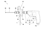
- FIG. 1 is a schematic view showing the overall configuration of the drilling device according to the present embodiment.
- the drilling device 10A according to the present embodiment includes an electric drill 11, a pump unit 20 attached to the electric drill 11, and a drill bit 90 attached to the electric drill 11 via the pump unit 20.
- the drilling device 10A further includes a supply flow path 88 for supplying the coolant L to the cutting edge 98 of the drill bit 90.
- the drill bit 90 is rotationally driven by the electric drill 11, and the cutting edge 98 of the rotating drill bit 90 is pressed against a perforated object (not shown) such as concrete or stone. , Drilling work is done. Then, when the drilling operation is performed in this way, the coolant L in the supply flow path 88 is changed to the drill bit 90 by the pump unit 20 for the purpose of suppressing the heat generation of the drill bit 90 and the object to be drilled. It is pumped to the cutting edge 98.
- the drill bit 90 is formed hollow. As a result, the coolant L flows inside the drill bit 90, and the coolant L is supplied to the cutting edge 98 of the drill bit 90. The coolant L supplied to the cutting edge 98 of the drill bit 90 is discharged from the cutting edge 98 and suppresses heat generation of the drill bit 90 and the object to be drilled. Then, the coolant L is mixed with chips of the object to be perforated to form a suspension, which is discharged to the outside.
- a coolant tank (not shown) for storing the coolant L may be provided at the base end of the supply flow path 88.
- the coolant L is usually water, but may be, for example, another liquid having a low viscosity. Further, for example, when the object to be perforated is an iron plate, oil having a low viscosity may be used as the coolant L.
- the electric drill 11 is housed in the housing 12, a driving device 13 for rotationally driving the drill bit 90, and is provided outside the housing 12 and projects from the base end surface of the pump unit 20. It has a first gripping mechanism 18 for gripping the shank 22 and.
- the drive device 13 is attached to the electric motor 14 and the drive shaft 15 of the electric motor 14, and includes a motor deceleration mechanism 16 for reducing the rotational speed of the power of the electric motor 14 and then transmitting the power to the shank 22. Has.
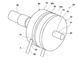
- FIG. 2 is an external perspective view of the pump unit included in the drilling device according to the present embodiment when viewed from the drive device side.
- the pump unit 20 includes a tube pump 60 for pumping the coolant L in the supply flow path 88 to the cutting edge 98 of the drill bit 90, and a drive device 13 and a tube pump 60 (in other words, a tube pump 60).
- a deceleration mechanism 30 provided between the first pressing mechanism 64), which will be described later, for transmitting the power to the tube pump 60 (same as above) after reducing the rotational speed of the power by the drive device 13. Have.
- the pump unit 20 further has an input shaft 21 for inputting power from the drive device 13 to the speed reduction mechanism 16.
- the input shaft 21 penetrates the pump unit 20 and extends from the drive device 13 toward the cutting edge 98 side.
- the pump unit 20 is provided at the tip of the input shaft 21 and further has a second gripping mechanism 80 for gripping the base end portion of the drill bit 90.
- the input shaft 21 is connected to the drill bit 90 via the second gripping mechanism 80 and rotates integrally with the drill bit 90.
- the base end portion of the input shaft 21 is the shank 22 described above.
- the speed reduction mechanism 30 includes two planetary gear mechanisms 31a and 31b that are arranged in parallel in the axial direction of the input shaft 21.
- the planetary gear mechanism 31a (the planetary gear mechanism on the most driving device side, or one of the planetary gear mechanisms adjacent to each other on the driving device side) is provided on the driving device 13 side.
- a planetary gear mechanism 31b (the planetary gear mechanism on the most cutting edge side or the other of the planetary gear mechanisms adjacent to each other on the cutting edge side) is provided on the drill bit 90 side.
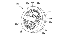
- FIG. 3 is an external perspective view showing a state in which the planetary gear mechanism on the most driving device side is being assembled, which is provided in the drilling device according to the present embodiment.
- the speed reduction mechanism 30 further includes a disk-shaped first disk 32.
- a through hole 33 (see FIG. 2) for the input shaft 21 to penetrate is provided in the center of the first disk 32.
- the end surface of the first disk 32 and the main surface of the first disk 32 on the drive device 13 side form a part of the outer shape of the pump unit 20.
- the planetary gear mechanism 31a includes a sun gear 34a arranged in the center of the first disk 32, three planetary gears 36a that rotate by engaging with the sun gear 34a by circumscribing the sun gear 34a, and three planetary gears.
- the internal gear 38a that meshes with and rotates with each of the three planetary gears 36a is further provided.
- the diameter of the internal gear 38a is the same as the diameter of the first disk 32.
- the end face of the internal gear 38a forms a part of the outer shape of the pump unit 20.
- the sun gear 34a protrudes from the outer surface of the input shaft 21 and is integrally formed with the outer surface of the input shaft 21. In other words, the sun gear 34a is fixed to the outer surface of the input shaft 21. As described above, the sun gear 34a rotates integrally with the input shaft 21 and is coaxial with the input shaft 21.
- FIG. 4 is an external perspective view showing a state in which a planetary carrier is attached to a planetary gear mechanism on the most driving device side, which is provided in the drilling device according to the present embodiment.
- the speed reduction mechanism 30 further includes a disk-shaped planetary carrier 50 for connecting the planetary gear mechanisms 31a and 31b to each other.
- the planetary carrier 50 has three fitting holes 52 (fitted portions) into which the rotating shafts 37a of the three planetary gears 36a are fitted. As a result, the planetary carrier 50 is connected to the three planetary gears 36a. Each of the three fitting holes 52 is provided on the peripheral edge of the planetary carrier 50 at equal intervals in the circumferential direction of the planetary carrier 50. Further, the planetary carrier 50 further has a shaft hole 54 (second shaft hole) through which the input shaft 21 penetrates. The shaft hole 54 is provided in the center of the planetary carrier 50.
- the sun gear 34b of the planetary gear mechanism 31b is integrally formed in the center of the main surface of the planetary carrier 50 on the cutting edge 98 side. As a result, the planetary carrier 50 rotates integrally with the sun gear 34b.
- FIG. 5 is an external perspective view showing a state in which a pressing portion is attached to each of a plurality of planetary gears of the planetary gear mechanism on the most cutting edge side of the drilling device according to the present embodiment.
- the speed reduction mechanism 30 further includes a second disk 56 arranged on the cutting edge 98 side of the planetary carrier 50.
- a through hole 58 is provided in the center of the second disk 56 for the input shaft 21 to penetrate and the sun gear 34b to pass through.
- the diameter of the second disk 56 is the same as the diameter of the first disk 32 and the internal gear 38a.
- the end face of the second disk 56 forms a part of the outer shape of the pump unit 20.
- the planetary gear mechanism 31a includes a sun gear 34b integrally formed with the planetary carrier 50 as described above, and three planetary gears 36b that rotate by engaging with the sun gear 34b by circumscribing the sun gear 34b.
- the internal gear 38b that meshes with and rotates with each of the three planetary gears 36b is further provided.
- the sun gear 34b has a shaft hole 35 (first shaft hole) through which the input shaft 21 penetrates.
- the shaft hole 35 communicates with the shaft hole 54 of the planetary carrier 50.
- the diameter of the internal gear 38b is the same as the diameter of the first disk 32, the second disk 56, and the internal gear 38a.
- the end face of the internal gear 38b constitutes a part of the outer shape of the pump unit 20.
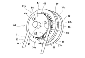
- FIG. 6 is an external perspective view showing a state in which the third disk and the supply tube are attached to the planetary gear mechanism on the most cutting edge side of the drilling device according to the present embodiment.
- FIG. 7 is an external perspective view of the pump unit included in the drilling device when viewed from the cutting edge side.
- the tube pump 60 has a supply tube 62 configured as a part of the supply flow path 88, and a first pressing mechanism 64 for pressing the supply tube 62.
- the first pressing mechanism 64 is provided on each of the three planetary gears 36b and has three rollers 66 (pressing portions) that rotate integrally with each of the three planetary gears 36b. ..
- the three rollers 66 are coaxial with each of the three planetary gears 36b and are attached to the rotating shafts 37b of each of the three planetary gears 36b.
- the first pressing mechanism 64 further includes a third disk 67 provided on the cutting edge 98 side of the three rollers 66.
- the third disk 67 has three fitting holes 68 into which the rotating shafts 37b of each of the three planetary gears 36b are fitted.
- the third disk 67 is connected to the three planetary gears 36b via the three rollers 66.
- Each of the three fitting holes 68 is provided on the peripheral edge of the third disk 67 at equal intervals in the circumferential direction of the third disk 67.
- the third disk 67 further has a through hole 69 through which the input shaft 21 penetrates. The through hole 69 is provided in the center of the third disk 67.
- the first pressing mechanism 64 provides an inner wall 72 that presses the supply tube 62 in cooperation with each of the three rollers 66 by inscribed each of the three rollers 66 via the supply tube 62. It further has a cover body 70 including.
- the cover body 70 has a hollow columnar shape and is coaxial with the input shaft 21.
- a through hole 73 for the input shaft 21 to penetrate is provided in the center of the bottom surface of the cover body 70 on the cutting edge 98 side.
- the bottom surface of the cover body 70 on the drive device 13 side is open.
- the inner wall 72 is an inner wall on the side surface of the cover body 70.
- the diameter of the cover body 70 is the same as the diameters of the first disk 32, the second disk 56, and the internal gears 38a and 38b.
- the bottom surface of the cover body 70 on the cutting edge 98 side and the side surface of the cover body 70 form a part of the outer shape of the pump unit 20.
- the rotation speed of the first pressing mechanism 64 can be made slower than that of the drill bit 90.
- the coolant L in the supply flow path 88 can be appropriately pumped to the cutting edge 98 of the drill bit 90 while rotating the drill bit 90 at a sufficient rotation speed, so that the drilling work can be performed satisfactorily. It becomes possible to do.
- the drilling device 10A can be made into a simpler device configuration.
- the tube pump 60 since the tube pump 60 is provided outside the housing 12, the tube pump 60 can be easily attached to and detached from the drive device 13 (in other words, the electric drill 11).
- FIG. 8 is a schematic view showing the overall configuration of the drilling device according to the present embodiment.
- the drilling device 10B according to the present embodiment mainly has the same structure as the drilling device 10A according to the first embodiment, except for the location where the tube pump 60 is arranged. Therefore, the same reference number is assigned to the same part, and the same description is not repeated.
- the tube pump 60 is provided inside the housing 12. Specifically, the tube pump 60 is arranged between the drive device 13 provided inside the housing 12 and the first gripping mechanism 18 provided outside the housing 12.
- the base end portion (that is, the shank 22) of the input shaft 21 of the tube pump 60 is connected to the motor deceleration mechanism 16 inside the housing 12.
- the motor deceleration mechanism 16 reduces the rotational speed of the power generated by the electric motor 14 and then transmits the power to the input shaft 21 of the pump unit 20.
- the shank 82 protrudes from the base end side of the second gripping mechanism 80. Then, the shank 82 is gripped by the first gripping mechanism 18 and is connected to the tip end portion of the input shaft 21 inside the first gripping mechanism 18.
- the power of the electric motor 14 is transmitted to the drill bit 90 by the above structure.
- the tube pump 60 since the tube pump 60 is housed inside the housing 12 and is not exposed to the outside, failure of the tube pump 60 can be suppressed.
- FIG. 9 is a schematic view showing the overall configuration of the drilling device according to the present embodiment.
- the drilling device 10C according to the present embodiment has the same structure as the drilling device 10B according to the second embodiment, except that the motor deceleration mechanism 16 is not provided. Therefore, the same reference number is assigned to the same part, and the same description is not repeated.
- the drilling device 10C does not include the motor deceleration mechanism 16, and the drive shaft 15 itself of the electric motor 14 is configured as an input shaft of the pump unit 20.
- the drive shaft 15 of the electric motor 14 and the input shaft of the pump unit 20 may be provided separately, and the base end portion of the input shaft may be directly attached to the tip end portion of the drive shaft 15. ..
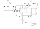
- FIG. 10 is a schematic view showing the overall configuration of the drilling device according to the present embodiment.
- the drilling device 10D according to the present embodiment has a structure similar to that of the drilling device 10B according to the second embodiment described above in many respects. Therefore, the same reference number is assigned to the same part, and the same description is not repeated.
- the drilling device 10D further includes a discharge flow path 138 for discharging the suspension S from the cutting edge 98.
- the tube pump 60 ′ further includes a discharge tube 112 configured as a part of the discharge flow path 138, and a second pressing mechanism 114 for pressing the discharge tube 112.
- an insertion hole 75'for inserting the discharge tube 112 into the cover body 70 from the cutting edge 98 side is provided in parallel with the insertion hole 75 of the supply tube 62. Further, on the side surface of the cover body 70, the discharge tube 112 is arranged side by side in the take-out hole 76 of the supply tube 62 (not shown in FIG. 10, see FIG. 7), and the discharge tube 112 is moved from the inside of the cover body 70 to the tank 150 side described later. A take-out hole (not shown) is provided for taking out.
- the insertion hole 75'and the take-out hole for the discharge tube 112 are the same as the insertion hole 75 and the take-out hole 76 on the cutting edge 98 side of the insertion hole 75 and the take-out hole 76 for the supply tube 62, respectively. It is provided at the height position.
- the first pressing mechanism 64 for pressing the supply tube 62 and the second pressing mechanism 114 for pressing the discharge tube 112 are configured as one pressing mechanism 64 (114).
- the pressing mechanism 64 (114) of the present embodiment has the same structure as the first pressing mechanism 64 described with reference to FIGS. 5 to 7.
- the three rollers 66 (see FIGS. 5 and 6) and the inner wall 72 (see FIG. 7) of the cover body 70 press the discharge tube 112 together with the supply tube 62.
- the pressing mechanism 64 (114) pumps the coolant L in the supply flow path 88 to the cutting edge 98, and in addition, sends the suspension S in the discharge flow path 138 downstream of the discharge flow path 138. Pump to the side.
- the upstream end of the supply flow path 88 and the downstream end of the discharge flow path 139 are used in the separation device 140 for separating the chips C of the object to be drilled from the suspension S to obtain the coolant L. Be connected.
- the separation device 140 has a liquid container 141 and an internal container 142 in the liquid container 141. Further, the separation device 140 can move integrally with the float 146 floating on the suspension S stored in the inner container 142 and the float 146 in the suspension S, and removes chips C from the suspension S. It has a strainer 147 for separation and.
- the suspension S When the suspension S is discharged into the inner container 142 from the downstream end of the discharge flow path 138, chips C and the like settle under its own weight. Further, the suspension S has a size that cannot pass through the chips C (between the slide member 167 and the rotating portion 161 described later, and between the inclined surface 167a and the seal member 165 described later) by the strainer 147 near the liquid surface thereof. Chips C) are further removed. As a result, the coolant L in which the chips C are separated from the suspension S can be supplied to the upstream end of the supply flow path 88 connected to the strainer 147.
- the drilling device 10D drills with the coolant supply mechanism 160 provided on the cutting edge 98 side of the housing 12 and the first gripping mechanism 18 and the cutting edge 98 of the drill bit 90.
- a shielding portion 200 that covers the perforated portion Wa of the object to be perforated W is further provided.
- the shielding portion 200 is urged forward by an urging mechanism 170 described later.
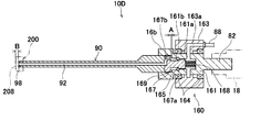
- FIG. 11 is a cross-sectional view of the coolant supply mechanism provided in the drilling device according to the present embodiment and its peripheral portion cut at the center in the width direction along the length direction.
- the coolant supply mechanism 160 includes a rotating portion 161 having a shank 82 gripped by the first gripping mechanism 18 of the electric drill 11, and a coolant supply portion 163 provided around the rotating portion 161. And have.
- the coolant supply unit 163 can be kept in a non-rotating state by the bearing 164 provided between the coolant supply unit 163 and the rotating unit 161.
- a supply flow path 88 is connected to the coolant supply unit 163.
- the supply flow path 163a provided inside the coolant supply unit 163 communicates with the supply flow path 161a provided in the rotating unit 161.
- a bit attachment portion 166 for gripping the base portion of the drill bit 90 is provided at the front portion of the rotating portion 161.
- the base of the drill bit 90 is inserted and held in the bit mounting portion 166.
- the mechanism for holding the base of the drill bit 90 is not shown.
- a mechanism for holding the base of the drill bit 90 a known technique can be used.
- a slide member 167 capable of moving a predetermined amount in the front-rear direction (in other words, the length direction of the drill bit 90) with the base of the drill bit 90 in contact with the rotating portion 161. ..
- the slide member 167 is urged forward by an urging member 168 (spring) provided inside the rotating portion 161.
- An inclined surface 167a having an enlarged diameter is provided at the rear portion of the slide member 167, and the inclined surface 167a abuts on the seal member 165 provided at a predetermined position of the rotating portion 161 by the urging force of the urging member 168.
- the front portion of the slide member 167 is sealed by a sealing member 169 provided between the slide member 167 and the bit mounting portion 166.
- An O-ring can be used for the seal members 165 and 169.
- the slide member 167 can slide backward against the urging force of the urging member 168 within a predetermined amount of the gap A between the sliding member 167 and the rotating portion 161.
- the space 161b between the slide member 167 and the rotating portion 161 communicates with the coolant supply hole 92 provided in the drill bit 90 via the supply flow path 167b provided in the slide member 167.
- the coolant supply hole 92 is provided from the base of the drill bit 90 to the cutting edge 98.
- the slide member 167 when the slide member 167 is pressed from the direction of the drill bit 90 (state of FIG. 14B described later), the slide member 167 resists the urging force of the urging member 168 and has a predetermined amount of gap A. Move backward with. In this state, the inclined surface 167a is separated from the seal member 165, and the supply flow path 161a and the space 161b communicate with each other, and the cooling liquid L supplied from the supply flow path 88 flows from the supply flow path 161a to the space 161b. Flow to.
- the coolant L stops in a state of being supplied to the coolant supply mechanism 160, and the drill bit 90 is pushed backward to the coolant supply mechanism 160.
- the supplied coolant L is supplied from the cutting edge 98 to the drilled portion Wa through the coolant supply hole 92 of the drill bit 90.
- the drilling device 10D is attached to the base end of the drill bit 90, and together with the drill bit 90, a slide member 167 that can slide in the length direction of the drill bit 90 and the drill bit 90.
- the slide member 167 is further provided with an urging member 168 for urging the slide member 167 from the base end side of the drill bit 90 toward the cutting edge 98 side. Then, the slide member 167 closes the supply flow path 88 when it is located on the cutting edge 98 side by the urging force of the urging member 168, and supplies the slide member 167 when it slides to the base end side against the urging force of the urging member 168. It is arranged so as to open the flow path 88.
- the predetermined amount of gap A in which the slide member 167 moves in the front-rear direction is formed by the drill bit 90 from the front surface of the shielding portion 200 in a state where the slide member 167 is urged forward by the urging mechanism 170 described later. It is smaller than the arrangement gap B up to the cutting edge 98 (see FIGS. 11 and 14 (B)).
- the arrangement gap B is pushed in by a predetermined amount of the gap A, and then the inclined surface 167a of the slide member 167 is separated from the sealing member 165. become.
- the coolant L is supplied from the cutting edge 98 in a state where the seal member 208 of the shielding portion 200 is pressed against the object to be drilled W (see FIG. 14B), and the shielding portion 200 and the object to be drilled W It is possible to prevent the coolant L from leaking from between.
- the relationship between the predetermined gap A and the arrangement gap B is an example, and is not limited to this embodiment.
- FIG. 12A and 12B are schematic views showing a shielding portion included in the drilling device according to the present embodiment, in which FIG. 12A is a schematic view when viewed from the base end side of the drill bit, and FIG. It is sectional drawing at the time of cutting along the vertical direction.
- the main body portion 201 is formed in a horizontally long shape, and connecting portions 202 are provided at both ends thereof.
- the slide portion 175 of the urging mechanism 170 shown in FIG. 13 is connected to the connecting portion 202.
- a guide member 203 for guiding the front portion of the drill bit 90 in the front-rear direction is provided in the central portion of the main body portion 201.
- the guide member 203 is provided with a guide portion 204 of the drill bit 90 in the central portion and a space portion 205 in the front portion.
- a seal member 206 is provided between the guide member 203 and the main body 201 to prevent the suspension S from leaking between them.
- An O-ring can be used for the seal member 206.
- a seal member 208 in contact with the object to be perforated W is provided on the front surface of the main body 201.
- the sealing member 208 is provided so as to seal the periphery of the space portion 205 and the periphery of the perforated portion Wa.
- a sponge material, a rubber material, or the like can be used as the sealing member 208.
- a discharge hole 207 leading from the space 205 to the outside is provided in the lower part of the main body 201.
- a discharge flow path 138 is connected to the discharge hole 207. The suspension S in the space 205 is discharged from the discharge hole 207 into the discharge flow path 138.
- FIG. 13 is a schematic view showing an urging mechanism included in the drilling device according to the fourth embodiment of the present invention.
- FIG. 13 is a semi-cross-sectional view.
- the urging mechanism 170 of this embodiment has a main body portion 171 attached to the coolant supply mechanism 160 of the drilling device 10D.
- the main body 171 is fixed to the outer surface of the coolant supply mechanism 160.
- the main body 171 is provided with two guide portions 173 extending in the front-rear direction and a slide portion 175 that slides in the front-rear direction along the guide portion 173 at the left and right positions of the coolant supply mechanism 160.
- the guide portion 173 is inserted into the hole portion of the main body portion 171 and is fixed to the main body portion 171 by fixing the two positions at the left and right positions with the fixing bolts 172.
- the slide portion 175 is urged forward by an urging spring 174 provided inside the guide portion 173.
- the slide portion 175 is held by the holding portion 176 provided at the end of the guide portion 173 so that the slide portion 175 stops and slides forward at a predetermined position shown in the drawing.
- the slide portion 175 can slide backward against the urging force of the urging spring 174 from the state shown in the drawing.
- a shielding portion 200 is fixed to the tip of the slide portion 175. As a result, the shielding portion 200 can move backward integrally with the slide portion 175 against the urging force of the urging spring 174.
- FIG. 14 is a cross-sectional view when the coolant supply mechanism and its peripheral portion included in the drilling device according to the present embodiment are cut at the center in the width direction along the length direction
- FIG. 14A is a cross-sectional view before the drilling operation. It is a cross-sectional view when the supply flow path is closed
- (B) is a cross-sectional view when the supply flow path is open during the drilling operation.
- the drilling device 10D is connected to the separation device 140 via the supply flow path 88 and the discharge flow path 138. Then, the pump unit 20'and the drill bit 90 are operated by the drive device 13, and the cutting edge 98 of the drilling device 10D is arranged in the drilled portion Wa of the object W to be drilled. In this state, the tube pump 60'presses the supply tube 62 to supply the coolant L from the liquid container 141 to the cutting edge 98 of the drill bit 90. However, as shown in FIG. 14A, since the slide member 167 of the coolant supply mechanism 160 comes into contact with the seal member 165 and the tip of the supply flow path 161a is closed, the coolant L is discharged from the liquid container 141. Not supplied.
- the tube pump 60' is in a state of pressing the discharge tube 112 and sucking air from the space portion 205 (FIG. 12 (B)) of the shielding portion 200 into the discharge flow path 138.
- the seal member 208 of the shielding portion 200 provided in the drilling device 10D is applied to the drilled portion Wa of the object to be drilled W.
- the cutting edge 98 of the drill bit 90 is pressed toward the object W to be drilled while rotating the drill bit 90 by operating the operation portion 12a provided on the housing 12.
- the shielding portion 200 is in a state of being pressed against the perforated object W by an urging mechanism 170 with an appropriate force.
- the base of the drill bit 90 rearward the slide member 167 against the urging force of the urging member 168 within a predetermined amount of the gap A. Move to.
- the inclined surface 167a of the slide member 167 is separated from the seal member 165, and the supply flow path 163a of the coolant supply unit 163 becomes the supply flow path 161a of the rotating unit 161, the space 161b, and the supply flow path 167b of the slide member 167. It communicates with the coolant supply hole 92 of the drill bit 90 via. Therefore, when the object W to be drilled is drilled with the cutting edge 98 of the drill bit 90, the coolant L supplied from the liquid container 141 to the coolant supply mechanism 160 is supplied from the cutting edge 98 of the drill bit 90 to the drilled portion Wa. .. Then, the suspension S in the space portion 205 (see FIG. 12B) of the shielding portion 200 is pushed to the liquid container 141 by the discharge tube 112 being pressed by the pressing mechanism 64 (114) (see FIG. 10). Is forcibly discharged.
- the drill bit 90 by rotating the drill bit 90 and pressing the cutting edge 98 against the front punched object W, the drilled portion Wa of the drilled object W is punched by the cutting edge 98.
- the supply tube 62 is pressed by the pressing mechanism 64 (114), so that the coolant L of the liquid container 141 is forcibly supplied from the cutting edge 98 of the drilling device 10D to the drilled portion Wa, and
- the discharge tube 112 is pressed by the pressing mechanism 64 (114)
- the suspension S is forcibly discharged from the shielding portion 200 to the liquid container 141.
- the suspension S discharged into the liquid container 141 becomes a coolant L when the chips C and the like settle under its own weight and the chips C are removed by the strainer 147 floating near the liquid surface, and the coolant L becomes the coolant L. Is supplied to the cutting edge 98 again. That is, the cooling liquid L supplied from the suspension S stored in the liquid container 141 to the cutting edge 98 of the drill bit 90 attached to the drilling device 10D is supplied to the liquid surface having few chips C in the suspension S and its vicinity. By obtaining it from the portion via the strainer 147, the coolant L with less mixing of chips C is circulated to the cutting edge 98 of the drilling device 10D. Moreover, since the tube pump 60'is used to circulate the coolant L, even if some chips C are mixed in the coolant L, it can be circulated appropriately.
- the drilling device 10D covers the cooling liquid L while appropriately supplying the coolant L to the cutting edge 98 and performing circulation in which the backflow is appropriately suppressed by forcibly discharging the suspension S. It is possible to perform an appropriate drilling operation on the drilled object W.
- the coolant L is appropriate even in the downward drilling operation. Circulation is possible. Therefore, it is possible to appropriately perform drilling work in various directions.
- a trolley for transporting the separation device 140 may be provided. This makes it easy to move the entire system. The entire system can be easily moved by providing a backpack and a shoulder bag instead of the dolly. Further, as shown in FIG. 10, if the battery 19 is built in the electric drill 11, it can be easily moved with the separating device 140 mounted on the trolley, so that the position of the drilling work can be easily changed. Even in a relatively small work site, it is possible to perform drilling work appropriately.
- the electric drill 11 of the drilling device 10D is not limited to the configuration in which the battery 19 is built-in. The electric drill 11 may be configured to be supplied with electric power via a power cord 19a (see FIGS. 1, 8 and 9) as in the above-mentioned drilling devices 10A to 10C.
- the reduction mechanism 30 has two planetary gear mechanisms 31a and 31b parallel to each other in the axial direction of the input shaft 21 .
- the reduction mechanism is not limited to this case, and may have, for example, three or more planetary gear mechanisms arranged in parallel in the axial direction of the input shaft 21.
- the three or more planetary gear mechanisms may have a sun gear, three planetary gears, and an internal gear, respectively, like the planetary gear mechanisms 31a and 31b.
- planetary carriers are provided between the planetary gear mechanisms adjacent to each other.
- the planetary carrier is connected to a plurality of planetary gears of one of the planetary gear mechanisms adjacent to each other on the drive device side, and is integrated with the sun gear of the other of the planetary gear mechanisms adjacent to each other on the cutting edge side. Rotate.
- the sun gear 34a protrudes from the outer surface of the input shaft 21 and is integrally formed with the outer surface of the input shaft 21 has been described.
- the present invention is not limited to this case, and among the plurality of planetary gear mechanisms, the sun gear possessed by the planetary gear mechanism on the most driving device side does not have to be integrally formed with the outer surface of the input shaft.
- the sun gear may be fixed to the outer surface of the input shaft by having the sun gear having a shaft hole and fixing the inner wall of the shaft hole to the outer surface of the input shaft.
- the present invention is not limited to this case, and the plurality of planetary gear mechanisms may each have two planetary gears, or may have four or more planetary gears. It should be noted that the plurality of planetary gear mechanisms may each have a different number of planetary gears.
- the sun gears 34a and 34b are coaxial with the input shaft 21 .
- the present invention is not limited to this case, and the sun gear may not be coaxial with the input shaft, for example, by appropriately adding other gears.
- the planetary carrier 50 has three fitting holes 52 (fitted portions) into which the rotation shafts 37a of the three planetary gears 36a are fitted has been described. ..
- the present invention is not limited to this case, and the planetary carrier may have a recess as a fitted portion into which the rotation shafts of the plurality of planetary gears are fitted, for example.
- the speed reduction mechanism 30 has two planetary gear mechanisms 31a and 31b parallel to each other in the axial direction of the input shaft 21 .
- the speed reduction mechanism is not limited to this case, and may be configured as, for example, a harmonic drive (registered trademark).
- the first pressing mechanism is, for example, a rotating plate (or a rotating body) attached to the input shaft of the harmonic drive (registered trademark) so as to rotate in a plane orthogonal to the input shaft, and the rotating body. It may have at least one pressing portion provided on the peripheral edge of the rotating plate (same as above). Then, in the first pressing mechanism, at least one pressing portion is inscribed via the supply tube (and the discharge tube), so that the supply tube (and the discharge tube) is pressed in cooperation with each of the at least one pressing portion. It may further have a cover body including an inner wall to be formed. Even with such a structure, the tube pump pumps the coolant in the supply flow path to the cutting edge (and pumps the suspension S in the discharge flow path to the downstream side of the discharge flow path). Is possible.
- the first pressing mechanism 64 for pressing the supply tube 62 and the second pressing mechanism 114 for pressing the discharge tube 112 are configured as one pressing mechanism 64 (114) and supplied.
- the present invention is not limited to this case, and for example, by separately configuring the first pressing mechanism and the second pressing mechanism, another pressing portion provided separately from the pressing portion for pressing the supply tube may be used.
- the discharge tube may be pressed.
- the drilling device includes a cutting edge, a driving device for rotationally driving the cutting edge, and a supply flow path for supplying a cooling liquid to the cutting edge.
- a tube pump for pumping the coolant in the supply flow path to the cutting edge is provided, and the tube pump presses the supply tube formed as a part of the supply flow path and the supply tube.
- the first pressing mechanism is provided, and the first pressing mechanism is driven by the driving device.
- the tube pump is driven by a driving device for rotationally driving the cutting edge, it is possible to pump the coolant to the cutting edge with a simple device configuration.
- a deceleration mechanism provided between the driving device and the first pressing mechanism for transmitting the power to the first pressing mechanism after reducing the rotational speed of the power by the driving device may be further provided. ..
- the rotation speed of the first pressing mechanism can be made slower than that of the cutting edge, so that the drilling work can be performed satisfactorily.
- the deceleration mechanism is further provided with an input shaft for inputting power from the drive device, and the input shaft extends at least through the deceleration mechanism and extends from the drive device to the cutting edge side, and the deceleration mechanism.
- Each of the plurality of planetary gear mechanisms is in contact with the sun gear, the plurality of planetary gears that rotate in mesh with the sun gear by externally contacting the sun gear, and the plurality of planetary gears, respectively.
- the planetary carrier is connected to a plurality of planetary gears of one of the planetary gear mechanisms adjacent to each other on the drive device side, and the planetary carrier is connected to the plurality of planetary gears of the planetary gear mechanisms adjacent to each other.
- the first pressing mechanism rotates integrally with the sun gear possessed by the other on the cutting edge side, and the plurality of planetaries possessed by the planetary gear mechanism on the most cutting edge side among the plurality of planetary gear mechanisms.
- a plurality of pressing portions provided on each of the gears and rotating integrally with the plurality of planetary gears, and the plurality of pressing portions are inscribed via the supply tube to form a plurality of pressing portions. It has a cover body including an inner wall that cooperates to press the supply tube.
- the sun gear possessed by each of the plurality of planetary gear mechanisms is provided coaxially with the input shaft, and among the plurality of planetary gear mechanisms, the sun gear possessed by the planetary gear mechanism on the drive device side is the sun gear.
- the sun gear fixed to the input shaft and having a planetary gear mechanism other than the planetary gear mechanism on the drive device side among the plurality of planetary gear mechanisms is a first shaft through which the input shaft penetrates. It may have holes.
- the drilling device can be made into a simpler device configuration.
- the planetary carrier includes a plurality of fitted portions into which the rotation shafts of the plurality of planetary gears possessed by one of the drive device sides of the planetary gear mechanisms adjacent to each other are fitted, and the input. It may have a second shaft hole through which the shaft penetrates.
- At least a housing for accommodating the drive device may be further provided.
- the tube pump may be provided outside the housing.
- the tube pump can be easily attached to and detached from the drive device.
- the tube pump may be housed in the housing.
- the cutting edge is configured as the tip of the drill bit, the drill bit, a slide member attached to the base end of the drill bit and slidable together with the drill bit in the length direction of the drill bit, the drill bit, and the drill bit.
- the slide member is further provided with an urging member for urging the slide member from the base end side of the drill bit toward the cutting edge side, and the slide member is moved to the cutting edge side by the urging force of the urging member.
- the supply flow path may be arranged so as to close the supply flow path when it is positioned and open the supply flow path when it slides toward the base end side against the urging force of the urging member.
- the tube pump includes a discharge tube configured as a part of the discharge flow path and a second pressing mechanism for pressing the discharge tube.
- the suspension in the discharge flow path may be pumped to the downstream side of the discharge flow path by further having the above and driving the second pressing mechanism by the drive device.
- the suspension can be forcibly discharged from the cutting edge to the downstream side of the discharge flow path. Therefore, for example, when the perforated portion of the object to be drilled is at a position lower than the downstream end of the discharge flow path. Even when the drilling operation is performed with the cutting edge facing downward, the suspension can be reliably discharged to the downstream side of the discharge flow path.
- the first and second pressing mechanisms are configured as one pressing mechanism, and the pressing mechanism presses the discharge tube together with the supply tube to push the coolant in the supply flow path to the cutting edge.
- the suspension in the discharge channel may be pumped to the downstream side of the discharge channel.
- the upstream end of the supply flow path and the downstream end of the discharge flow path may be connected to a separation device for separating chips of the object to be drilled from the suspension to obtain the coolant.
- the coolant can be circulated, so that the drilling operation can be repeated without preparing a new coolant.
- Drilling device 11 Electric drill 12 Housing 13 Drive device 14 Electric motor 15 Drive shaft 16 Motor deceleration mechanism 18 First gripping mechanism 20 Pump unit 21 Input shaft 22, 82 Shank 30 Deceleration mechanism 31a, 31b Planetary gear mechanism 32 First Disc 33, 58, 69, 73 Through Hole 34a, 34b Sun Gear 35, 54 Shaft Hole 36a, 36b Planetary Gear 37a, 37b Rotating Shaft 38a, 38b Internal Gear 50 Planetary Carrier 52, 68 Fitting Hole 56 2nd disc 60, 60'Tube pump 62 Supply tube 64 1st pressing mechanism 66 Roller (pressing part) 67 3rd disk 70 Cover body 72 Inner wall 75, 75'Insert hole 76 Extraction hole 80 2nd gripping mechanism 88 Supply flow path 90 Drill bit 92 Coolant supply hole 98 Cutting edge 112 Discharge tube 114 2nd pressing mechanism 138 Discharge flow path 140 Separator 160 Coolant supply mechanism 167 Slide member 168 Biasing member L Coolant S Suspension W Per
Landscapes
- Engineering & Computer Science (AREA)
- Mechanical Engineering (AREA)
- General Engineering & Computer Science (AREA)
- Mining & Mineral Resources (AREA)
- Drilling And Boring (AREA)
Abstract
Description
図1は、本実施形態に係る穿孔装置の全体構成を示す概略図である。図1に示すように、本実施形態に係る穿孔装置10Aは、電動ドリル11と、電動ドリル11に取り付けられるポンプユニット20と、ポンプユニット20を介して電動ドリル11に取り付けられるドリルビット90と、を備える。また、穿孔装置10Aは、ドリルビット90の刃先98に冷却液Lを供給するための供給流路88をさらに備える。
電動ドリル11は、筐体12と、筐体12内に収容され、ドリルビット90を回転駆動するための駆動装置13と、筐体12の外部に設けられ、ポンプユニット20の基端面から突出するシャンク22を把持するための第1把持機構18と、を有する。
図2は、本実施形態に係る穿孔装置が備えるポンプユニットを駆動装置側から見たときの外観斜視図である。図2に示すように、ポンプユニット20は、供給流路88内の冷却液Lをドリルビット90の刃先98へと圧送するためのチューブポンプ60と、駆動装置13とチューブポンプ60(換言すれば、後述する第1押圧機構64)との間に設けられ、駆動装置13による動力の回転速度を減じてから前記動力をチューブポンプ60(同前)へと伝達するための減速機構30と、を有する。
減速機構30は、入力軸21の軸方向に並列される二つのプラネタリーギヤ機構31a、31bを備える。プラネタリーギヤ機構31a(最も駆動装置側のプラネタリーギヤ機構、又は、互いに隣接するプラネタリーギヤ機構のうち駆動装置側の一方)が、駆動装置13側に設けられる。また、プラネタリーギヤ機構31b(最も刃先側のプラネタリーギヤ機構、又は、互いに隣接するプラネタリーギヤ機構のうち刃先側の他方)が、ドリルビット90側に設けられる。
図6は、本実施形態に係る穿孔装置が備える、最も刃先側のプラネタリーギヤ機構に第3円板及び供給チューブを取り付けた様子を示す外観斜視図である。また、図7は、同穿孔装置が備えるポンプユニットを刃先側から見たときの外観斜視図である。
上記構造によれば、本実施形態に係る穿孔装置10Aは、チューブポンプ60が刃先98を回転駆動するための駆動装置13によって駆動されるので、簡単な装置構成で刃先98に冷却液を圧送することが可能となる。
図8に基づき、本発明の第2実施形態に係る穿孔装置について説明する。図8は、本実施形態に係る穿孔装置の全体構成を示す概略図である。なお、本実施形態に係る穿孔装置10Bは、主として、チューブポンプ60の配置箇所を除き、上記した第1実施形態に係る穿孔装置10Aと同様の構造を備える。したがって、同一部分には同じ参照番号を付し、同様となる説明は繰り返さない。
図9に基づき、本発明の第3実施形態に係る穿孔装置について説明する。図9は、本実施形態に係る穿孔装置の全体構成を示す概略図である。なお、本実施形態に係る穿孔装置10Cは、モータ減速機構16を備えないことを除いて、上記した第2実施形態に係る穿孔装置10Bと同様の構造を備える。したがって、同一部分には同じ参照番号を付し、同様となる説明は繰り返さない。
図10~14に基づき、本発明の第4実施形態に係る穿孔装置について説明する。図10は、本実施形態に係る穿孔装置の全体構成を示す概略図である。なお、本実施形態に係る穿孔装置10Dは、上記した第2実施形態に係る穿孔装置10Bと多くの点で同様の構造を備える。したがって、同一部分には同じ参照番号を付し、同様となる説明は繰り返さない。
分離装置140は、液体容器141と、液体容器141内の内部容器142と、を有する。また、分離装置140は、内部容器142に貯えられた懸濁液Sに浮かべられるフロート146と、懸濁液S内でフロート146と一体的に移動可能であり、懸濁液Sから切屑Cを分離するためのストレーナ147と、を有する。
図12は、本実施形態に係る穿孔装置が備える遮蔽部を示す概略図であり、(A)がドリルビットの基端側から見たときの概略図、(B)が幅方向の中央を長さ方向に沿って切断したときの断面図である。この実施形態の遮蔽部200は、本体部201が横長に形成され、その両端部に連結部202が設けられている。連結部202には、図13に示す付勢機構170のスライド部175が連結される。本体部201の中央部分には、ドリルビット90の前部を前後方向に案内する案内部材203が設けられている。案内部材203には、中央部分にドリルビット90の案内部204が設けられ、前方部分には空間部205が設けられている。案内部材203と本体部201との間にはシール部材206が設けられており、これらの間から懸濁液Sが漏れるのを防止している。シール部材206は、Oリングを用いることができる。
図13は、本発明の第4実施形態に係る穿孔装置が備える付勢機構を示す概略図である。図13は、半断面図で示している。この実施形態の付勢機構170は、穿孔装置10Dの冷却液供給機構160に取り付けられる本体部171を有している。本体部171は、冷却液供給機構160の外面に固定されている。
図14は、本実施形態に係る穿孔装置が備える冷却液供給機構及びその周辺部分を幅方向の中央で長さ方向に沿って切断したときの断面図であり、(A)が穿孔作業前であって供給流路が閉じているときの断面図、(B)が穿孔作業を行っている際中であって供給流路が開いているときの断面図である。図10及び図14に基づいて、穿孔装置10D及び分離装置140を用いて被穿孔物Wに対して穿孔作業を行う一例について説明する。
上記説明から、当業者にとっては、本発明の多くの改良や他の実施形態が明らかである。したがって、上記説明は、例示としてのみ解釈されるべきであり、本発明を実行する最良の態様を当業者に教示する目的で提供されたものである。本発明の精神を逸脱することなく、その構造及び/又は機能の詳細を実質的に変更できる。
上記課題を解決するために、本発明の一実施形態に係る穿孔装置は、刃先と、前記刃先を回転駆動するための駆動装置と、前記刃先に冷却液を供給するための供給流路と、前記供給流路内の前記冷却液を前記刃先へと圧送するためのチューブポンプと、を備え、前記チューブポンプは、前記供給流路の一部として構成される供給チューブと、前記供給チューブを押圧するための第1押圧機構と、を有し、前記第1押圧機構が前記駆動装置によって駆動されることを特徴とする。
11 電動ドリル
12 筐体
13 駆動装置
14 電動モータ
15 駆動軸
16 モータ減速機構
18 第1把持機構
20 ポンプユニット
21 入力軸
22、82 シャンク
30 減速機構
31a、31b プラネタリーギヤ機構
32 第1円板
33、58、69、73 貫通孔
34a、34b サンギヤ
35、54 軸孔
36a、36b プラネタリーギヤ
37a、37b 回転軸
38a、38b インターナルギヤ
50 プラネタリーキャリア
52、68 嵌合孔
56 第2円板
60、60´ チューブポンプ
62 供給チューブ
64 第1押圧機構
66 ローラ(押圧部)
67 第3円板
70 カバー体
72 内壁
75、75´ 挿入孔
76 取り出し孔
80 第2把持機構
88 供給流路
90 ドリルビット
92 冷却液供給孔
98 刃先
112 排出チューブ
114 第2押圧機構
138 排出流路
140 分離装置
160 冷却液供給機構
167 スライド部材
168 付勢部材
L 冷却液
S 懸濁液
W 被穿孔物
Claims (12)
- 刃先と、
前記刃先を回転駆動するための駆動装置と、
前記刃先に冷却液を供給するための供給流路と、
前記供給流路内の前記冷却液を前記刃先へと圧送するためのチューブポンプと、を備え、
前記チューブポンプは、前記供給流路の一部として構成される供給チューブと、前記供給チューブを押圧するための第1押圧機構と、を有し、
前記第1押圧機構が前記駆動装置によって駆動されることを特徴とする、穿孔装置。 - 前記駆動装置と前記第1押圧機構との間に設けられ、前記駆動装置による動力の回転速度を減じてから前記動力を前記第1押圧機構へと伝達するための減速機構をさらに備える、請求項1に記載の穿孔装置。
- 前記減速機構に前記駆動装置による動力を入力するための入力軸をさらに備え、
前記入力軸は、少なくとも前記減速機構を貫通して、前記駆動装置から前記刃先側へと延び、
前記減速機構は、前記入力軸の軸方向に並列される複数のプラネタリーギヤ機構と、前記複数のプラネタリーギヤ機構のうち、互いに隣接するプラネタリーギヤ機構同士を接続するためのプラネタリーキャリアと、を有し、
前記複数のプラネタリーギヤ機構は、それぞれ、サンギヤと、前記サンギヤに外接することで、前記サンギヤと噛み合って回転する複数のプラネタリーギヤと、前記複数のプラネタリーギヤそれぞれが内接することで、前記複数のプラネタリーギヤそれぞれと噛み合って回転するインターナルギヤと、を有し、
前記複数のプラネタリーギヤ機構のうち、最も前記駆動装置側のプラネタリーギヤ機構が有する前記サンギヤは、前記入力軸と一体的に回転し、
前記プラネタリーキャリアは、前記互いに隣接するプラネタリーギヤ機構のうち前記駆動装置側の一方が有する前記複数のプラネタリーギヤに接続され、前記互いに隣接するプラネタリーギヤ機構のうち前記刃先側の他方が有する前記サンギヤと一体的に回転し、
前記第1押圧機構は、
前記複数のプラネタリーギヤ機構のうち、最も前記刃先側のプラネタリーギヤ機構が有する前記複数のプラネタリーギヤそれぞれに設けられ、前記複数のプラネタリーギヤそれぞれと一体的に回転する複数の押圧部と、
前記複数の押圧部それぞれが前記供給チューブを介して内接することで、前記複数の押圧部それぞれと協働して前記供給チューブを押圧する内壁を含むカバー体と、を有する、請求項2に記載の穿孔装置。 - 前記複数のプラネタリーギヤ機構それぞれが有する前記サンギヤは、前記入力軸と同軸状に設けられ、
前記複数のプラネタリーギヤ機構のうち、最も前記駆動装置側のプラネタリーギヤ機構が有する前記サンギヤは、前記入力軸に固定され、
前記複数のプラネタリーギヤ機構のうち、最も前記駆動装置側のプラネタリーギヤ機構以外のプラネタリーギヤ機構が有する前記サンギヤは、前記入力軸が貫通するための第1軸孔を有する、請求項3に記載の穿孔装置。 - 前記プラネタリーキャリアは、前記互いに隣接するプラネタリーギヤ機構のうちの前記駆動装置側の一方が有する前記複数のプラネタリーギヤそれぞれの回転軸が嵌合される複数の被嵌合部と、前記入力軸が貫通するための第2軸孔と、を有する、請求項3又は4に記載の穿孔装置。
- 少なくとも前記駆動装置を収容するための筐体をさらに備える、請求項1乃至5のいずれかに記載の穿孔装置。
- 前記チューブポンプは、前記筐体の外部に設けられる、請求項6に記載の穿孔装置。
- 前記チューブポンプは、前記筐体内に収容される、請求項6に記載の穿孔装置。
- 前記刃先は、ドリルビットの先端として構成され、
前記ドリルビットと、
前記ドリルビットの基端に取り付けられ、前記ドリルビットとともに前記ドリルビットの長さ方向にスライド可能なスライド部材と、
前記ドリルビット及び前記スライド部材を、前記ドリルビットの基端側から前記刃先側に向けて付勢するための付勢部材と、をさらに備え、
前記スライド部材は、前記付勢部材の付勢力により前記刃先側に位置しているとき前記供給流路を閉じ、前記付勢部材の付勢力に抗して前記基端側にスライドしたとき前記供給流路を開くように配置される、請求項1乃至8のいずれかに記載の穿孔装置。 - 前記刃先から懸濁液を排出するための排出流路をさらに備え、
前記チューブポンプは、前記排出流路の一部として構成される排出チューブと、前記排出チューブを押圧するための第2押圧機構と、をさらに有し、前記第2押圧機構が前記駆動装置によって駆動されることで、前記排出流路内の前記懸濁液を前記排出流路の下流側へと圧送する、請求項1乃至9のいずれかに記載の穿孔装置。 - 前記第1及び前記第2押圧機構は、一の押圧機構として構成され、
前記押圧機構は、前記供給チューブとともに前記排出チューブも押圧することで、前記供給流路内の前記冷却液を前記刃先へと圧送することに加えて、前記排出流路内の前記懸濁液を前記排出流路の下流側へと圧送する、請求項10に記載の穿孔装置。 - 前記供給流路の上流端及び前記排出流路の下流端は、前記懸濁液から被穿孔物の切屑を分離して前記冷却液を得るための分離装置に接続される、請求項11に記載の穿孔装置。
Priority Applications (4)
| Application Number | Priority Date | Filing Date | Title |
|---|---|---|---|
| KR1020227035414A KR102770025B1 (ko) | 2020-03-31 | 2021-02-22 | 천공 장치 |
| EP21781678.4A EP4129600A4 (en) | 2020-03-31 | 2021-02-22 | DRILLING DEVICE |
| US17/905,477 US12397473B2 (en) | 2020-03-31 | 2021-02-22 | Boring device |
| CN202180022620.3A CN115315344B (zh) | 2020-03-31 | 2021-02-22 | 穿孔装置 |
Applications Claiming Priority (4)
| Application Number | Priority Date | Filing Date | Title |
|---|---|---|---|
| JP2020062957 | 2020-03-31 | ||
| JP2020-062957 | 2020-03-31 | ||
| JP2020-151051 | 2020-09-09 | ||
| JP2020151051A JP7582649B2 (ja) | 2020-03-31 | 2020-09-09 | 穿孔装置 |
Publications (1)
| Publication Number | Publication Date |
|---|---|
| WO2021199791A1 true WO2021199791A1 (ja) | 2021-10-07 |
Family
ID=77928297
Family Applications (1)
| Application Number | Title | Priority Date | Filing Date |
|---|---|---|---|
| PCT/JP2021/006611 Ceased WO2021199791A1 (ja) | 2020-03-31 | 2021-02-22 | 穿孔装置 |
Country Status (5)
| Country | Link |
|---|---|
| US (1) | US12397473B2 (ja) |
| EP (1) | EP4129600A4 (ja) |
| KR (1) | KR102770025B1 (ja) |
| CN (1) | CN115315344B (ja) |
| WO (1) | WO2021199791A1 (ja) |
Families Citing this family (3)
| Publication number | Priority date | Publication date | Assignee | Title |
|---|---|---|---|---|
| CN117464473B (zh) * | 2023-11-23 | 2024-11-08 | 盐城市山川金属加工有限公司 | 一种打磨抛光机床设备 |
| CN117696947B (zh) * | 2023-12-13 | 2026-02-27 | 中国第一汽车股份有限公司 | 一种变径孔加工装置及方法 |
| CN120460772B (zh) * | 2025-07-09 | 2025-10-31 | 泰州虹康电子科技有限公司 | 一种改性纳米金刚石涂层微型钻头及涂层生长方法 |
Citations (5)
| Publication number | Priority date | Publication date | Assignee | Title |
|---|---|---|---|---|
| JPH04217411A (ja) * | 1990-12-20 | 1992-08-07 | Miyanaga:Kk | 穿孔用給水装置 |
| JP2005145041A (ja) * | 2003-10-23 | 2005-06-09 | Ishihara Kikai Kogyo Kk | ノンコアタイプビット、ノンコアドリル装置およびその冷却水給排水方法 |
| JP2007313855A (ja) | 2006-05-29 | 2007-12-06 | Fs Technical Corp | 穿孔方法、ハイドロフルオロエーテルおよび穿孔装置 |
| JP2017196846A (ja) * | 2016-04-28 | 2017-11-02 | 日立工機株式会社 | 注液機構及びこれを用いた穿孔機 |
| JP2019107754A (ja) * | 2017-12-20 | 2019-07-04 | 株式会社神名テックス | 掘削装置及び掘削方法 |
Family Cites Families (17)
| Publication number | Priority date | Publication date | Assignee | Title |
|---|---|---|---|---|
| JP3826383B2 (ja) * | 1995-05-30 | 2006-09-27 | 東邦金属工業株式会社 | 回転ドリル装置 |
| JP3858233B2 (ja) * | 1997-02-18 | 2006-12-13 | 東邦金属工業株式会社 | 湿式回転ドリル装置 |
| JP3521399B2 (ja) * | 1999-09-02 | 2004-04-19 | 株式会社呉英製作所 | 穿孔機用液体循環装置 |
| US6595196B2 (en) * | 2000-06-22 | 2003-07-22 | Michael Bath | Dust-free masonry cutting tool |
| JP4628555B2 (ja) * | 2000-08-29 | 2011-02-09 | ナブテスコ株式会社 | 油圧駆動減速装置 |
| JP3623927B2 (ja) | 2001-05-15 | 2005-02-23 | 株式会社呉英製作所 | 携帯式循環濾過装置 |
| JP2005030260A (ja) * | 2003-07-09 | 2005-02-03 | Ckd Corp | チューブポンプ |
| SE531738C2 (sv) * | 2006-09-01 | 2009-07-28 | Husqvarna Ab | Borrmaskin |
| JP5106492B2 (ja) * | 2009-08-17 | 2012-12-26 | 株式会社ホリ・コン | 冷却剤供給アタッチメントおよびこれを備えた穿孔装置 |
| KR100990817B1 (ko) | 2010-03-17 | 2010-10-29 | 손정헌 | 호스 펌프 |
| JP5446050B2 (ja) * | 2010-04-30 | 2014-03-19 | 日立工機株式会社 | 回転切削装置 |
| WO2014129119A1 (ja) * | 2013-02-19 | 2014-08-28 | Fsテクニカル株式会社 | 拡径用ドリルビット |
| EP3085973A4 (en) * | 2014-05-15 | 2017-07-26 | FS Technical Corporation | Post-installed anchor, post-installed anchor implementation method, post-installed anchor system and rotation-stopping tool |
| KR20160095012A (ko) * | 2014-11-20 | 2016-08-10 | 에프에스 테크니칼 코포레이션 | 앵커 구멍의 형성 방법 및 확경 장치 |
| JP6081666B1 (ja) * | 2015-04-13 | 2017-02-15 | Fsテクニカル株式会社 | 拡径用ドリルビット |
| FR3069472B1 (fr) * | 2017-07-25 | 2019-08-09 | Seti-Tec | Perceuse comprenant des moyens mecaniques de regulation du debit de lubrification en fonction des efforts de coupe |
| CN208951233U (zh) * | 2018-09-10 | 2019-06-07 | 北京长城华冠汽车技术开发有限公司 | 行星齿轮减速器及车辆 |
-
2021
- 2021-02-22 US US17/905,477 patent/US12397473B2/en active Active
- 2021-02-22 WO PCT/JP2021/006611 patent/WO2021199791A1/ja not_active Ceased
- 2021-02-22 CN CN202180022620.3A patent/CN115315344B/zh active Active
- 2021-02-22 KR KR1020227035414A patent/KR102770025B1/ko active Active
- 2021-02-22 EP EP21781678.4A patent/EP4129600A4/en active Pending
Patent Citations (5)
| Publication number | Priority date | Publication date | Assignee | Title |
|---|---|---|---|---|
| JPH04217411A (ja) * | 1990-12-20 | 1992-08-07 | Miyanaga:Kk | 穿孔用給水装置 |
| JP2005145041A (ja) * | 2003-10-23 | 2005-06-09 | Ishihara Kikai Kogyo Kk | ノンコアタイプビット、ノンコアドリル装置およびその冷却水給排水方法 |
| JP2007313855A (ja) | 2006-05-29 | 2007-12-06 | Fs Technical Corp | 穿孔方法、ハイドロフルオロエーテルおよび穿孔装置 |
| JP2017196846A (ja) * | 2016-04-28 | 2017-11-02 | 日立工機株式会社 | 注液機構及びこれを用いた穿孔機 |
| JP2019107754A (ja) * | 2017-12-20 | 2019-07-04 | 株式会社神名テックス | 掘削装置及び掘削方法 |
Non-Patent Citations (1)
| Title |
|---|
| See also references of EP4129600A4 |
Also Published As
| Publication number | Publication date |
|---|---|
| EP4129600A1 (en) | 2023-02-08 |
| EP4129600A4 (en) | 2024-05-15 |
| CN115315344A (zh) | 2022-11-08 |
| US20230118075A1 (en) | 2023-04-20 |
| KR20220156021A (ko) | 2022-11-24 |
| CN115315344B (zh) | 2025-11-25 |
| KR102770025B1 (ko) | 2025-02-20 |
| US12397473B2 (en) | 2025-08-26 |
Similar Documents
| Publication | Publication Date | Title |
|---|---|---|
| KR102770025B1 (ko) | 천공 장치 | |
| CN103161922A (zh) | 动力传输装置 | |
| JP2021160342A (ja) | 穿孔装置 | |
| JP2013228055A (ja) | 建設機械の駆動装置 | |
| CN101977727B (zh) | 旋转式流通接头和研磨装置 | |
| JP7557866B2 (ja) | 液体循環システム及びそれを備える穿孔システム | |
| JP4486864B2 (ja) | 孔あけ工具 | |
| JP2009262017A (ja) | 遊星運動式脱泡システム及び遊星運動式脱泡方法 | |
| JP6686677B2 (ja) | 注液機構及びこれを用いた穿孔機 | |
| JP6715393B2 (ja) | 減速装置 | |
| CN220497319U (zh) | 一种土壤修复药剂渗透注入机 | |
| KR102845912B1 (ko) | 액체 순환 시스템 및 이를 구비하는 천공 시스템 | |
| JP3623927B2 (ja) | 携帯式循環濾過装置 | |
| EP4502427A1 (en) | Traveling device for wheeled vehicle | |
| CN107620579B (zh) | 水平井井下修井工具 | |
| JP2008231682A (ja) | 削孔方法及び削孔装置 | |
| KR102172563B1 (ko) | 협소부 천공 기능 및 미세먼지 포집기능을 향상시킨 코어 천공기 | |
| CN216045343U (zh) | 齿轮箱和具有其的车辆 | |
| CN115922639A (zh) | 动力工具 | |
| JP2009114976A (ja) | 真空ポンプ | |
| CN220462978U (zh) | 一种齿轮传动的内铣动力刀座 | |
| JP2021104602A (ja) | 穿孔補助装置、及びそれを備える穿孔システム | |
| CN105042051A (zh) | 变速箱装置 | |
| JP5113805B2 (ja) | 流体継手 | |
| JP2017052211A (ja) | 偏心型穿孔装置 |
Legal Events
| Date | Code | Title | Description |
|---|---|---|---|
| 121 | Ep: the epo has been informed by wipo that ep was designated in this application |
Ref document number: 21781678 Country of ref document: EP Kind code of ref document: A1 |
|
| ENP | Entry into the national phase |
Ref document number: 20227035414 Country of ref document: KR Kind code of ref document: A |
|
| NENP | Non-entry into the national phase |
Ref country code: DE |
|
| ENP | Entry into the national phase |
Ref document number: 2021781678 Country of ref document: EP Effective date: 20221031 |
|
| WWG | Wipo information: grant in national office |
Ref document number: 1020227035414 Country of ref document: KR |
|
| WWG | Wipo information: grant in national office |
Ref document number: 17905477 Country of ref document: US |