WO2021199830A1 - 点検支援装置、方法及びプログラム - Google Patents
点検支援装置、方法及びプログラム Download PDFInfo
- Publication number
- WO2021199830A1 WO2021199830A1 PCT/JP2021/007649 JP2021007649W WO2021199830A1 WO 2021199830 A1 WO2021199830 A1 WO 2021199830A1 JP 2021007649 W JP2021007649 W JP 2021007649W WO 2021199830 A1 WO2021199830 A1 WO 2021199830A1
- Authority
- WO
- WIPO (PCT)
- Prior art keywords
- damage
- detected
- types
- image
- inspection support
- Prior art date
- Legal status (The legal status is an assumption and is not a legal conclusion. Google has not performed a legal analysis and makes no representation as to the accuracy of the status listed.)
- Ceased
Links
Images


Classifications
-
- G—PHYSICS
- G01—MEASURING; TESTING
- G01N—INVESTIGATING OR ANALYSING MATERIALS BY DETERMINING THEIR CHEMICAL OR PHYSICAL PROPERTIES
- G01N21/00—Investigating or analysing materials by the use of optical means, i.e. using sub-millimetre waves, infrared, visible or ultraviolet light
- G01N21/84—Systems specially adapted for particular applications
- G01N21/88—Investigating the presence of flaws or contamination
- G01N21/8851—Scan or image signal processing specially adapted therefor, e.g. for scan signal adjustment, for detecting different kinds of defects, for compensating for structures, markings, edges
-
- G—PHYSICS
- G06—COMPUTING OR CALCULATING; COUNTING
- G06T—IMAGE DATA PROCESSING OR GENERATION, IN GENERAL
- G06T7/00—Image analysis
- G06T7/0002—Inspection of images, e.g. flaw detection
-
- G—PHYSICS
- G06—COMPUTING OR CALCULATING; COUNTING
- G06T—IMAGE DATA PROCESSING OR GENERATION, IN GENERAL
- G06T7/00—Image analysis
- G06T7/0002—Inspection of images, e.g. flaw detection
- G06T7/0004—Industrial image inspection
-
- G—PHYSICS
- G06—COMPUTING OR CALCULATING; COUNTING
- G06V—IMAGE OR VIDEO RECOGNITION OR UNDERSTANDING
- G06V10/00—Arrangements for image or video recognition or understanding
- G06V10/20—Image preprocessing
- G06V10/25—Determination of region of interest [ROI] or a volume of interest [VOI]
-
- G—PHYSICS
- G06—COMPUTING OR CALCULATING; COUNTING
- G06V—IMAGE OR VIDEO RECOGNITION OR UNDERSTANDING
- G06V10/00—Arrangements for image or video recognition or understanding
- G06V10/70—Arrangements for image or video recognition or understanding using pattern recognition or machine learning
- G06V10/74—Image or video pattern matching; Proximity measures in feature spaces
- G06V10/761—Proximity, similarity or dissimilarity measures
-
- G—PHYSICS
- G06—COMPUTING OR CALCULATING; COUNTING
- G06V—IMAGE OR VIDEO RECOGNITION OR UNDERSTANDING
- G06V10/00—Arrangements for image or video recognition or understanding
- G06V10/70—Arrangements for image or video recognition or understanding using pattern recognition or machine learning
- G06V10/764—Arrangements for image or video recognition or understanding using pattern recognition or machine learning using classification, e.g. of video objects
-
- G—PHYSICS
- G01—MEASURING; TESTING
- G01N—INVESTIGATING OR ANALYSING MATERIALS BY DETERMINING THEIR CHEMICAL OR PHYSICAL PROPERTIES
- G01N21/00—Investigating or analysing materials by the use of optical means, i.e. using sub-millimetre waves, infrared, visible or ultraviolet light
- G01N21/84—Systems specially adapted for particular applications
- G01N21/88—Investigating the presence of flaws or contamination
- G01N21/8851—Scan or image signal processing specially adapted therefor, e.g. for scan signal adjustment, for detecting different kinds of defects, for compensating for structures, markings, edges
- G01N2021/8854—Grading and classifying of flaws
-
- G—PHYSICS
- G01—MEASURING; TESTING
- G01N—INVESTIGATING OR ANALYSING MATERIALS BY DETERMINING THEIR CHEMICAL OR PHYSICAL PROPERTIES
- G01N21/00—Investigating or analysing materials by the use of optical means, i.e. using sub-millimetre waves, infrared, visible or ultraviolet light
- G01N21/84—Systems specially adapted for particular applications
- G01N21/88—Investigating the presence of flaws or contamination
- G01N21/8851—Scan or image signal processing specially adapted therefor, e.g. for scan signal adjustment, for detecting different kinds of defects, for compensating for structures, markings, edges
- G01N2021/8887—Scan or image signal processing specially adapted therefor, e.g. for scan signal adjustment, for detecting different kinds of defects, for compensating for structures, markings, edges based on image processing techniques
-
- G—PHYSICS
- G01—MEASURING; TESTING
- G01N—INVESTIGATING OR ANALYSING MATERIALS BY DETERMINING THEIR CHEMICAL OR PHYSICAL PROPERTIES
- G01N21/00—Investigating or analysing materials by the use of optical means, i.e. using sub-millimetre waves, infrared, visible or ultraviolet light
- G01N21/84—Systems specially adapted for particular applications
- G01N21/88—Investigating the presence of flaws or contamination
- G01N21/95—Investigating the presence of flaws or contamination characterised by the material or shape of the object to be examined
- G01N21/9515—Objects of complex shape, e.g. examined with use of a surface follower device
-
- G—PHYSICS
- G06—COMPUTING OR CALCULATING; COUNTING
- G06T—IMAGE DATA PROCESSING OR GENERATION, IN GENERAL
- G06T2207/00—Indexing scheme for image analysis or image enhancement
- G06T2207/10—Image acquisition modality
- G06T2207/10024—Color image
-
- G—PHYSICS
- G06—COMPUTING OR CALCULATING; COUNTING
- G06T—IMAGE DATA PROCESSING OR GENERATION, IN GENERAL
- G06T2207/00—Indexing scheme for image analysis or image enhancement
- G06T2207/20—Special algorithmic details
- G06T2207/20081—Training; Learning
-
- G—PHYSICS
- G06—COMPUTING OR CALCULATING; COUNTING
- G06T—IMAGE DATA PROCESSING OR GENERATION, IN GENERAL
- G06T2207/00—Indexing scheme for image analysis or image enhancement
- G06T2207/20—Special algorithmic details
- G06T2207/20084—Artificial neural networks [ANN]
-
- G—PHYSICS
- G06—COMPUTING OR CALCULATING; COUNTING
- G06T—IMAGE DATA PROCESSING OR GENERATION, IN GENERAL
- G06T2207/00—Indexing scheme for image analysis or image enhancement
- G06T2207/30—Subject of image; Context of image processing
- G06T2207/30108—Industrial image inspection
- G06T2207/30132—Masonry; Concrete
-
- G—PHYSICS
- G06—COMPUTING OR CALCULATING; COUNTING
- G06T—IMAGE DATA PROCESSING OR GENERATION, IN GENERAL
- G06T2207/00—Indexing scheme for image analysis or image enhancement
- G06T2207/30—Subject of image; Context of image processing
- G06T2207/30181—Earth observation
- G06T2207/30184—Infrastructure
Definitions
- the present invention relates to an inspection support device, a method and a program, and particularly to a technique for supporting the inspection of a structure.
- Patent Document 1 the inner wall surface of the tunnel is photographed with a camera, and the captured image is image-processed to extract and quantify cracks in each subdivision of the inner wall surface, and crack information is displayed for each subdivision.
- a crack detection method and a display method thereof are disclosed. For example, the cracks are displayed in different colors for each subdivision according to the degree of cracks in each subdivision, so that the degree of cracks can be easily grasped.
- Patent Document 1 there is a description that cracks are displayed in different colors for each sub-category according to the degree of cracks in each sub-category, but there is a description that two or more types (multi-items) of damage are detected from a structure. There is no description on how to output the detection results of multi-item damage.
- the present invention has been made in view of such circumstances, and when two or more types of damage are detected in a structure, and in particular, two or more types of damage are detected from the same or adjacent positions of the structure. It is an object of the present invention to provide an inspection support device, a method and a program capable of outputting damage detection results satisfactorily.
- the invention according to the first aspect is an inspection support device including a processor, in which the processor acquires an image of a structure to be inspected, an image acquisition process, and the acquired image.
- the damage detection process that detects damage to the structure based on the damage detection process
- two or more types of damage from the same or adjacent positions among the two or more types of damage. It is a judgment process that determines whether or not the damage is detected, and an output process that outputs the damage detection result detected by the damage detection process.
- an output process for outputting the damage detection result according to the priority of the damage type is performed.
- two or more types of damage to the structure are detected based on an image of the structure to be inspected, and in particular, two or more types of damage are detected from the same or similar positions of the structure. If it is detected, the damage detection result is output according to the priority as the damage detection result. As a result, when two or more types of damage are detected from the same or close positions of the structure, the damage detection results are output according to the priority of the damage types, so that the damage detection results are output from the same or close positions of the structure. It is possible to deal with the case where two or more types of damage are detected. When two or more types of damage are not located at the same or close to each other in the structure, the two or more types of damage detection results can be output as they are.
- the damage detection process detects the damaged area and the damage type for each damaged area based on the image, and the determination process is the same or adjacent damage area by the damage detection process. Determines whether or not two or more types of damage have been detected, and the output process is the same when it is determined by the determination process that two or more types of damage have been detected in the same or adjacent damage areas.
- the adjacent positions are positions where the distance between two or more types of damage is equal to or less than the threshold value.
- the damage detection process is executed by a trained model that outputs the damage area and the damage type for each damage area as a recognition result when an image is input.
- the output process outputs different drawing patterns depending on whether the damage type is linear damage or the damage type is planar damage.
- the output process outputs a damage diagram showing a line showing a line that does not close the linear damage when the damage type is linear damage, and when the damage type is planar damage. It is preferable to output a damage diagram showing a closed line surrounding the planar damage.
- a damage diagram showing a line that does not close the linear damage is used, and if the damage type is planar damage, a closed line surrounding the planar damage is shown. It is a damage diagram.
- the output process outputs a damage image in which at least the linear damage is filled when the damage type is linear damage, and at least a surface when the damage type is surface damage. It is preferable to output a damage image in which the shape damage is filled.
- the output process outputs the damage detection result to the display and displays it, or saves the damage detection result as a file in the memory.
- the priority of the damage type is preferably a preset priority according to the severity of the damage.
- the linear free lime in the case of linear free lime and linear damage including cracks as damage types, the linear free lime has a higher priority than cracks.
- the types of damage include exposure of reinforcing bars, peeling, and so on.
- planar damage including rust juice, planar free lime, and water leakage
- the priority is set in the order of reinforcing bar exposure, peeling, rust juice, planar free lime, and water leakage.
- the processor performs a priority reception process for receiving the priority of the damage type of the structure from the operation unit operated by the user, and the priority of the damage type is determined by the user. This is the priority received via the operation unit.
- the processor edits the damage detection result according to the edit instruction reception process for receiving the edit instruction of the damage detection result from the operation unit operated by the user and the received edit instruction. It is preferable to perform an editing process.
- the damage detection result has items of damage identification information, damage type and size, and a damage quantity table in which information corresponding to each item is described for each detected damage. Is preferably included.
- the invention according to the fifteenth aspect is an inspection support method for supporting inspection of a structure to be inspected by a processor, and each process of the processor includes a step of acquiring an image of the structure to be inspected and the acquisition.
- the damage type is prioritized. It includes a step of outputting the damage detection result according to the order.
- the invention according to the 16th aspect is an inspection support program for causing a computer to execute a method of performing inspection support for a structure to be inspected, wherein the method includes a step of acquiring an image of the structure to be inspected and acquisition. Whether or not two or more types of damage were detected from the same or adjacent positions among the two or more types of damage of the detected structure and the step of detecting two or more types of damage to the structure based on the obtained image. And a step to output the detected damage detection result. If it is determined by the determination step that two or more types of damage are detected from the same or adjacent positions, the damage type is determined. It includes a step of outputting the damage detection result according to the priority.
- the damage detection result is satisfactorily output. Can be done.
- FIG. 1 is a diagram showing an example of damage to a structure.
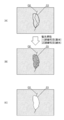
- FIG. 2 is a diagram showing an example of linear free lime.
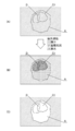
- FIG. 3 is a diagram showing an example of planar free lime.
- FIG. 4 is a diagram showing the types of damage expression methods according to the type of damage, FIG. 4 (A) shows an image including cracks, and FIG. 4 (B) shows a polyline along the cracks. It is a figure which shows the image which was made.
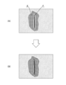
- FIG. 5 is a diagram showing the types of damage expression methods according to the type of damage, FIG. 5 (A) shows an image including peeling and rebar exposure, and FIG. 5 (B) shows peeling and rebar exposure. It is a figure which shows the image in which the polygon surrounding the area of is drawn.
- FIG. 5 shows an image including peeling and rebar exposure
- FIG. 6 is a diagram showing the types of damage expression methods according to the type of damage
- FIG. 6 (A) shows an image containing planar free lime
- FIG. 6 (B) is a planar image. It is a figure which shows the image which the polygon surrounding the region of free lime is drawn.
- FIG. 7 is a diagram showing each polyline when cracks and linear free lime, which are linear damages, are detected.
- FIG. 8 is a diagram used for explaining the proximity determination between the crack which is the linear damage shown in FIG. 7 and the linear free lime.
- FIG. 9 is a block diagram showing an example of the hardware configuration of the inspection support device according to the present invention.
- FIG. 10 is a conceptual diagram showing an embodiment of a damage detection processing unit configured by a CPU or the like.
- FIG. 10 is a conceptual diagram showing an embodiment of a damage detection processing unit configured by a CPU or the like.
- FIG. 11 is a perspective view showing an example of a bridge to be inspected.
- FIG. 12 is a diagram showing an example of an orthoimage corresponding to a coffer, which is one of the inspection units of a bridge.
- FIG. 13 is a diagram showing an example of the damage detection result detected based on the ortho image shown in FIG.
- FIG. 14 is a diagram showing an example of an ortho image on which a damage diagram corresponding to a coffer is superimposed.
- FIG. 15 is a chart showing an example of a damage quantity table included in the damage detection result.
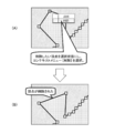
- FIG. 16 is a schematic view showing an example of the damage detection result of cracks and linear free lime by the damage detection processing unit and the output processing thereof.
- FIG. 17 is a schematic view showing the damage detection results of cracks and linear free lime by the damage detection processing unit and other examples of the output processing thereof.
- FIG. 18 is a schematic view showing an example of the damage detection results of planar free lime and linear free lime by the damage detection processing unit and the output processing thereof.
- FIG. 19 is a schematic view showing the damage detection results of planar free lime and linear free lime by the damage detection processing unit, and other examples of the output processing thereof.
- FIG. 20 is a schematic view showing an example of the damage detection results of rust juice, planar free lime and water leakage by the damage detection processing unit, and the output processing thereof.
- FIG. 21 is a schematic view showing the damage detection results of rust juice, planar free lime and water leakage by the damage detection processing unit, and other examples of the output processing thereof.
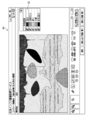
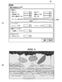
- FIG. 22 is an image diagram showing a GUI showing a second embodiment of damage detection result output, and is a diagram showing an example of a screen displayed on the display unit.
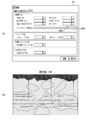
- FIG. 23 is an image diagram showing a GUI showing a second embodiment of damage detection result output, and is a diagram showing another example of a screen displayed on the display unit.
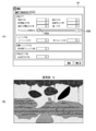
- FIG. 24 is an image diagram of a GUI showing a third embodiment of damage detection result output, and FIG. 24A shows a case where “10” is set as the transparency of the fill color of the damage image.
- FIG. 24 (B) is a diagram showing a composite image in which a damaged image having a transparency of “10” is superimposed and displayed on an image obtained by photographing the structure.
- FIG. 25 is an image diagram of a GUI showing a third embodiment of damage detection result output, and FIG. 25 (A) shows a case where “50” is set as the transparency of the fill color of the damage image.
- FIG. 25 (B) is a diagram showing a composite image in which a damaged image having a transparency of “50” is superimposed and displayed on an image obtained by photographing the structure.
- FIG. 26 is an image diagram of a GUI showing a third embodiment of damage detection result output, and FIG. 26A shows a case where “100” is set as the transparency of the fill color of the damage image.
- 26 (B) is a diagram showing a composite image in which a damaged image having a transparency of "100” is superimposed and displayed on an image obtained by photographing a structure.
- FIG. 27 is a diagram showing a method of adding vertices to a polygon surrounding a damaged area.
- FIG. 28 is a diagram showing a method of removing vertices from polygons surrounding a damaged area.
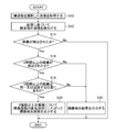
- FIG. 29 is a flowchart showing an embodiment of the inspection support method according to the present invention.
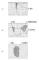
- FIG. 1 is a diagram showing an example of damage to a structure, and particularly shows damage to concrete members constituting the structure.
- FIG. 1 (A) shows water leakage A, which is one of the phenomena caused by damage to the concrete member.
- Leakage A is water leaking from the damaged portion due to damage to the concrete member (crack, crack at the joint, defective joint material, etc.).
- FIG. 1B shows cracks B, free lime C 1 , and rust juice D generated in the concrete member.
- Free lime C 1 is a phenomenon in which lime components flow out from the concrete member due to water leakage or the like and the lime component is exposed to the surface when the water evaporates.
- the rust juice D refers to a product in which a steel material such as a reinforcing bar inside a concrete member is corroded and a brown corrosion product exudes to the concrete surface.
- FIG. 1C shows the peeling E and the exposed reinforcing bar F generated in the concrete member.
- the peeling E means a state in which the concrete piece in the floating state is peeled off
- the reinforcing bar exposure F means a state in which the reinforcing bar in the concrete is exposed as a result of the peeling E.
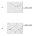
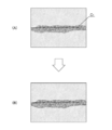
- FIG. 2 is a diagram showing an example of linear free lime
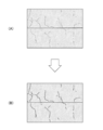
- FIG. 3 is a diagram showing an example of planar free lime.
- the linear free lime C 2 shown in FIGS. 2 (A) and 2 (B) is in a state where the cracks generated in the concrete member are clogged with the lime component. Therefore, the linear free lime C 2 and the crack have substantially the same shape, and the linear free lime C 2 is cracked at the same position (region) as the linear free lime C 2. There is.
- planar free lime shown in FIG. 3 (A) spreads below the crack as water leaks from the crack extending in the horizontal direction.
- the planar free lime C 1 shown in FIG. 3 (B) spreads around the cracks at the seams, and the planar free lime C 1 shown in FIG. 3 (C) spreads around the concrete cracks. There is.
- One aspect of the present invention detects damage to a structure from an image of the structure to be inspected, and outputs a damage detection result according to the type of the detected damage.
- FIGS. 4 to 6 are diagrams showing the types of damage expression methods according to the types of damage.
- FIG. 5 when peeling E and reinforcing bar exposure F are detected (FIG. 5 (A)), as a method of expressing peeling E and reinforcing bar exposure F, a closed line (polygon) surrounding the area of planar damage is used. ) Is represented by the drawing pattern (FIG. 5 (B)). This is because it is necessary to quantify the area in the case of planar damage such as peeling E.
- planar free lime C 1 when planar free lime C 1 is detected (FIG. 6 (A)), a closed line surrounding the area of planar damage is a way to represent planar free lime C 1. It is represented by a drawing pattern made of (polygons) (FIG. 6 (B)).
- planar free lime C 1 , peeling E, and rebar exposed F are all planar damages, but since the types of damage are different, polygons with different line types (for example, colors) can be identified. It is preferable to express it.
- the damage is expressed by a different drawing pattern according to the shape.
- linear free lime is represented by polylines
- planar free lime is represented by polygons.
- two or more types of damage may be detected from the same or adjacent positions on the structure (image).
- the adjacent position means a position where the distance between two or more types of damage is equal to or less than the threshold value.
- the threshold may be set by default or set by the user.
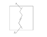
- FIG. 7 is a diagram showing each polyline when cracks and linear free lime, which are linear damages, are detected.
- X is a polyline showing cracks
- Y is a polyline showing linear free lime.
- FIG. 8 is a diagram used to explain the proximity judgment between the crack which is the linear damage shown in FIG. 7 and the linear free lime.
- the shortest distance between the point of interest P1 of the polyline X showing cracks (the first apex which is the end point of the polyline X) and the linear free lime polyline is L1.
- the shortest distance between the point of interest P2 (second vertex) of the poly line X and the poly line Y is L2
- the poly line X Let L3 be the shortest distance between the point of interest P3 (third vertex) and the polyline Y.
- the shortest distances of the two polylines X and Y are L4, L5, and L6, respectively.
- the shortest distance L4 is the shortest distance at the attention point 4 of the polyline Y (the apex which is the end point of the polyline Y)
- the shortest distance L5 is the attention point 5 of the polylines X and Y (the attention point 4 and the attention point 6).
- It is the shortest distance at the point of interest in the middle)
- the shortest distance L6 is the shortest distance at the point of interest 6 of the polyline X (the apex which is another end point of the polyline X).
- L1, L2, L3> threshold value is satisfied and L4, L5, L6 ⁇ threshold value is satisfied, it is determined that the two polylines Y and X (two damages) are “close” in the range of L4 to L6. do.
- the number of points of interest P1 to P6 is not limited to the above example.
- the distance between the two types of linear damage has been described, but the distance between the linear damage and the planar damage is also obtained by finding the shortest distance between each point of interest of the polyline and the polygon. , "Proximity" can be determined.
- priority is defined according to the type of damage, and when two or more types of damage are detected from the same or adjacent positions, the damage is expressed according to the priority. .. The details of the method of expressing damage according to the priority will be described later.
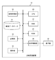
- FIG. 9 is a block diagram showing an example of the hardware configuration of the inspection support device according to the present invention.
- the inspection support device 10 shown in FIG. 1 a personal computer or a workstation can be used.
- the inspection support device 10 of this example mainly includes an image acquisition unit 12, an image database 14, a storage unit 16, an operation unit 18, a CPU (Central Processing Unit) 20, a RAM (Random Access Memory) 22, and a ROM. It is composed of (Read Only Memory) 24 and a display control unit 26.
- the image acquisition unit 12 corresponds to an input / output interface, and in this example, acquires a photographed image or the like of a structure to be inspected.
- the structures to be inspected include, for example, structures such as bridges and tunnels.
- the image acquired by the image acquisition unit 12 is, for example, a drone (unmanned flying object) equipped with a camera, a robot, or a large number of images (photographed image group) obtained by manually photographing a structure. It is preferable that the captured image group covers the entire structure and the adjacent captured images are duplicated.
- the captured image group acquired by the image acquisition unit 12 is stored in the image database 14.
- the storage unit 16 is a memory composed of a hard disk device, a flash memory, and the like.
- the storage unit 16 includes an operating system, an inspection support program, information indicating the priority of damage types, and a CAD (computer) indicating a structure. -aided design) Data and filed damage inspection results are stored.
- the damage inspection result can be stored as damage information in different layers for each type of damage.
- the damage information includes a damage diagram.
- the CAD data if the CAD data of the structure to be inspected exists, it can be used. When the CAD data of the structure does not exist, it can be automatically created based on the captured image group stored in the image database 14.
- the feature points between the captured images that overlap each other in the captured image group are extracted, and based on the extracted feature points, the feature points are extracted. It is possible to estimate the position and orientation of the camera mounted on the drone, and to generate a three-dimensional point cloud model in which the three-dimensional position of the feature point is estimated at the same time from the estimation result of the position and orientation of the camera.
- Structure from Motion which tracks the movement of a large number of feature points from a group of captured images in which the shooting position of the camera is moved by the drone, and simultaneously estimates the three-dimensional structure (Structure) and camera posture (Motion) of the structure.
- SfM three-dimensional structure
- bundle adjustment has been developed, and it has become possible to output with high accuracy.
- CAD data of the structure can be generated based on the generated 3D point cloud model.
- the operation unit 18 includes a keyboard, a mouse, and the like that are connected to the computer by wire or wirelessly, and functions as an operation unit that gives normal operation instructions to the computer.
- the operation unit 18 has a structure detected based on an image of the structure. It functions as an operation unit that edits the damage detection result of an object by user operation and sets the priority of a plurality of damage types of the structure by user operation. Details such as editing the damage detection result and setting the priority of the damage type will be described later.
- the CPU 20 reads various programs stored in the storage unit 16 or the ROM 24 or the like, controls each unit in an integrated manner, and detects damage to the structure (damage of two or more types) based on an image obtained by photographing the structure. It performs detection processing, determination processing for determining whether or not two or more types of damage are detected from the same or adjacent positions, and output processing for outputting the damage detection result detected by the damage detection processing.
- the damage detection process that detects two or more types of damage based on the captured image of the structure can be performed by artificial intelligence (AI).
- AI artificial intelligence
- a trained model by a convolutional neural network can be used.
- CNN convolutional neural network
- FIG. 10 is a conceptual diagram showing an embodiment of a damage detection processing unit configured by a CPU or the like.
- the damage detection processing unit 21 is composed of a plurality of (three in this example) trained models 21A, 21B, and 21C corresponding to a plurality of types of damage.
- Each trained model 21A, 21B, and 21C has an input layer, an intermediate layer, and an output layer, and each layer has a structure in which a plurality of "nodes" are connected by "edges".
- Image 13 of the structure is input to the input layer of CNN.
- the intermediate layer has a plurality of sets including a convolution layer and a pooling layer as one set, and is a portion for extracting features from an image input from an input layer.
- the convolution layer filters nearby nodes in the previous layer (performs a convolution operation using the filter) and acquires a "feature map”.
- the pooling layer reduces the feature map output from the convolution layer to a new feature map.
- the "convolution layer” plays a role of feature extraction such as edge extraction from an image, and the “pooling layer” plays a role of imparting robustness so that the extracted features are not affected by translation or the like.
- the output layer of CNN is the part that outputs the feature map showing the features extracted by the intermediate layer.
- the output layers of the trained models 21A, 21B, and 21C of this example are, for example, region classification (segmentation) in units of pixels for each damage of the structure shown in the image, or in units of a group of several pixels.
- the inference result is output as damage detection results 27A, 27B, 27C.
- the trained model 21A is a trained model machine-learned to detect damage to water leakage, planar free lime, and rust juice, and is a damaged region and damage of each of water leakage, planar free lime, and rust juice.
- the damage type for each area is output as a damage detection result (recognition result) 27A.
- the trained model 21B is a trained model machine-learned to detect damage of peeling / reinforcing bar exposure, and outputs the damaged areas of peeling / reinforcing bar exposure and the damage type for each damaged area as a damage detection result 27B. do.
- the trained model 21C is a trained model machine-learned to detect damage of cracks and linear free lime, and damage detection of each damaged region of cracks and linear free lime and the damage type for each damaged region. The result is output as 27C.
- the damage detection processing unit 21 is not limited to the above embodiment, for example, has an individual trained model for each damage type, and each trained model has a damage detection result corresponding to each damage type. It may be configured to output as. In this case, the same number of trained models as the number of damage types to be inspected will be provided. Further, it may have one trained model capable of dealing with all damage types, and may be configured to output the damage area and the damage type for each damage area as a damage detection result.
- the CPU 20 outputs the damage detection result detected by the damage detection process to the display unit (display) 30 via the display control unit 26 and displays it, or stores the damage detection result as a file. It is saved in the part (memory) 16.
- the RAM 22 is used as a work area of the CPU 20, and is used as a storage unit for temporarily storing the read program and various data.
- the display control unit 26 is a part that creates display data to be displayed on the display unit 30 and outputs it to the display unit 30.
- the damage detection result detected by the CPU 20 is displayed on the display unit 30, and the operation unit is operated.
- the display unit 30 displays a screen or the like for editing the damage detection result based on the user operation from 18.
- the display unit 30 uses various displays such as a liquid crystal monitor that can be connected to a computer, and displays an image of a structure input from the display control unit 26 as well as a damage detection result detected from the image. , Used as part of the user interface together with the operating unit 18.
- the processor including the CPU 20 of the inspection support device 10 having the above configuration performs each of the above processes by reading the inspection support program stored in the storage unit 16 or the ROM 24 and executing the inspection support program.
- FIG. 11 is a perspective view showing an example of a bridge to be inspected.
- the bridge 1 is provided in a direction orthogonal to the main girder 2 passed between the piers 7 and the main girder 2, and the horizontal girder 3 connecting the main girders and the main girder 2 are mutually connected. It is composed of various members including an anti-tilt structure 4 and a horizontal structure 5 connected to the main girder, and a floor slab 6 for traveling a vehicle or the like is placed on the upper part of the main girder or the like.
- the floor slab 6 is generally made of reinforced concrete.
- the floor slab 6 usually has a rectangular coffer defined by the main girder 2 and the cross girder 3 as a basic unit, and when inspecting damage to the floor slab (cracks, concrete peeling, etc.), the coffer It is done in units of intervals.
- Each coffer of the floor slab is one of the members (inspection unit) that make up the structure (bridge).
- the inspection unit of the bridge is the part / member classification (main girder 2, cross girder 3, anti-tilt structure 4, horizontal structure 5, pier 7 (column part, pillar)) that composes the structure. There are walls, beams, corners / joints)).
- the CPU 20 of the inspection support device 10 the inspection support program stored in the storage unit 16, the RAM 22 and ROM 24, the display control unit 26, and the like constitute a processor, and the processor performs various processes shown below.
- the processor performs an image acquisition process for acquiring an image of an inspection unit from a plurality of images of a structure (bridge 1) to be inspected stored in the image database 14.
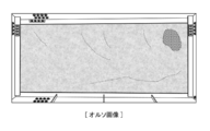
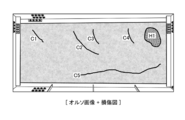
- FIG. 12 is a diagram showing an example of an ortho image corresponding to a coffer, which is one of the inspection units of a bridge.
- the ortho image is an image of a structure (coffer) photographed and projected onto the surface of the coffer.
- a plurality of images corresponding to the coffer are extracted from the captured image group stored in the image database 14, the extracted plurality of images are panoramicly combined, and the panoramic composite image is obtained. It can be created by projecting to a coffered surface.
- the damage detection processing unit 21 shown in FIG. 10 inputs an ortho image (image 13) of the coffer, the damage detection processing unit 21 detects the damage in the coffer based on the input image 13 and outputs the damage detection results 27A to 27C. ..
- FIG. 13 is a diagram showing an example of damage detection results detected based on the ortho image shown in FIG.
- the damage detection result shown in FIG. 13 shows a damage diagram showing damage between the coffers to be inspected.
- the damage diagram shown in FIG. 13 shows five cracks C1 to C5 and concrete peeling H1.
- the damage diagram shown in FIG. 13 shows a drawing pattern with polylines along each of the cracks C1 to C5 (linear damage) detected on the ortho image, and a drawing pattern with polygons surrounding the region of peeling H1 (plane damage). Alternatively, it is represented by an image in which the inside of the polygon is filled.
- FIG. 14 is a diagram showing an example of an ortho image on which a damage diagram corresponding to a coffer is superimposed.
- the ortho image on which the damage diagram shown in FIG. 14 is superimposed can be created by superimposing the damage diagram shown in FIG. 13 on the ortho image shown in FIG. 12.
- the damage diagram can be created by attaching a color corresponding to the type of damage to the damaged part, and by superimposing the damage diagram on the ortho image, the damaged part can be easily visually recognized.
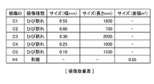
- FIG. 15 is a chart showing an example of a damage quantity table included in the damage detection result.
- the damage quantity table shown in FIG. 15 has items of damage identification information (ID: identification), damage type, size (width), size (length), and size (area), and each item corresponds to each damage. Information to be done is described.
- each crack C1 to C5 are quantified, and in the case of a peeling that is a planar damage, the area of the region of the peeling H1 is quantified. , This information is described in association with the damage ID.
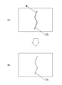
- FIG. 16 is a schematic view showing an example of the damage detection result of cracks and linear free lime by the damage detection processing unit and the output processing thereof.
- FIG. 16 (A) an image 13 is input to the flaw detection processing unit 21 (learned model 21C) shown in FIG. 10, each of the damaged region of the cracks B and linear free lime C 2 by a learned model 21C And the case where the damage detection result indicating the damage type for each damage area is detected is shown.
- the CPU 20 performs a determination process for determining whether or not these cracks B and the linear free lime C 2 are detected from the same or adjacent positions, respectively.
- the crack B and the linear free lime C 2 are shown side by side for convenience, but the linear free lime C 2 is formed on the crack B generated in the concrete member. It is in a state of being clogged with lime components. Therefore, the linear free lime C 2 and the crack B have substantially the same shape, and the linear free lime C 2 has a crack B at the same position (region) as the linear free lime C 2. doing.
- CPU 20 determines a free lime C 2 crack B and the line shape, to that detected from the same or adjacent locations . Then, when it is determined that the crack B and the linear free lime C 2 are detected from the same or adjacent positions, the CPU 20 performs an output process for outputting the damage detection result according to the priority of the damage type.
- the priority of the linear free lime C 2 is set higher than that of the crack B, so that the CPU 20 has the linear free lime as shown in FIG. 16 (B).
- the damage image in which the area of C 2 is filled is displayed on the display unit 30 via the display control unit 26, or the CAD data of the damage diagram showing the polyline of the linear free lime C 2 is output as a file. It is preferable that the CAD data file of the damage diagram is stored in the storage unit 16 in association with the image in which the damage is detected.
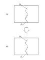
- FIG. 17 is a schematic diagram showing the damage detection results of cracks and linear free lime by the damage detection processing unit and other examples of the output processing thereof.
- the CPU 20 determines that a part of the crack B and a part of the linear free lime C 2 are detected from the same position. Then, the CPU 20 fills the area of the linear free lime C 2 with respect to the overlapping portion of the part of the crack B and the linear free lime C 2 as shown in FIG. 17 (B).
- the damage image is displayed on the display unit 30 via the display control unit 26, or the CAD data of the damage diagram showing the polyline of the linear free lime C 2 is output as a file.
- the CPU 20 causes the display unit 30 to display a damaged image in which the area of the crack B is filled as it is with the remaining portion of the crack B that does not overlap with the linear free lime C 2 via the display control unit 26.
- the CAD data of the damage diagram showing the polyline of the crack B is output as a file.
- the damage image and CAD data showing the crack B and the damage image and CAD data showing the linear free lime C 2 can be distinguished by changing the line type (for example, color), for example. ..
- FIG. 18 is a schematic view showing an example of the damage detection results of planar free lime and linear free lime by the damage detection processing unit and the output processing thereof.
- FIG. 18 damage detection processing unit 21 (trained model 21A, 21C) shown in FIG. 10 the image 13 respectively are inputted, the learned model 21A by planar free lime C 1 damaged region is detected is, the damaged region of the linear free lime C 2 is shown for when it is detected by the trained model 21C.
- the CPU 20 determines whether or not these planar free lime C 1 and linear free lime C 2 are detected from the same or adjacent positions, respectively.
- the CPU 20 and the planar free lime C 1 are generated. It is determined that the linear free lime C 2 is detected from the same or adjacent positions, respectively. Then, when it is determined that the planar free lime C 1 and the linear free lime C 2 are detected from the same or adjacent positions, the CPU 20 outputs the damage detection result according to the priority of the damage type. ..
- the CPU 20 has a surface as shown in FIG. 18 (B).
- the free lime C 1 planar give priority to the portion Jo of the free lime C 1 and linear free lime C 2 overlap, damaged images fill the damaged area of the planar free lime C1 a specific color Is displayed on the display unit 30 via the display control unit 26, and a damaged image in which a part of the non-overlapping linear free lime C 2 is filled is displayed on the display unit 30 via the display control unit 26.
- the polygon CPU20 for the free lime C 1 and the linear portion and the free lime C 2 overlap the planar as shown in FIG. 18 (C), which surrounds the planar damaged region of the free lime C 1 together with the CAD data, the CAD data of a part of polyline linear free non-overlapping lime C 2 to file output.
- FIG. 19 is a schematic view showing the damage detection results of planar free lime and linear free lime by the damage detection processing unit and other examples of the output processing thereof.
- the CPU 20 When a part of the planar free lime C 1 and the linear free lime C 2 overlap each other as shown in FIG. 19 (A), the CPU 20 has a planar free lime as shown in FIG. 19 (B).
- the damaged image in which the area of the linear free lime C 2 is filled is displayed with priority, and similarly, the linear free lime C 2 is displayed.
- Priority is given to the CAD data of the polyline of, and the file is output. In this case, for the planar free lime C 1, so that the damage image also CAD data is also not output.
- FIG. 20 is a schematic view showing an example of the damage detection results of rust juice, planar free lime and water leakage by the damage detection processing unit, and the output processing thereof.
- FIG. 20 (A) an image 13 is input to the flaw detection processing unit 21 (learned model 21A) shown in FIG. 10, rust juice D by trained model 21A, the planar free lime C 1 and leakage A It shows the case where the damaged area is detected.
- the CPU 20 determines whether or not these rust juice D, planar free lime C 1 and water leakage A are detected from the same or adjacent positions, respectively.
- the CPU 20 determines that these damages are detected from the same or adjacent positions, respectively. Then, when it is determined that the rust juice D, the planar free lime C 1 and the leak A are detected from the same or adjacent positions, the CPU 20 outputs the damage detection result according to the priority of the damage type.
- the CPU 20 since the priority is set to be lower in the order of rust juice D, planar free lime C 1 , and water leakage A, the CPU 20 has water leakage as shown in FIG. 20 (B). overlapping regions of free lime C 1 of planar over the a region, more overlapped regions of Sabijiru D on the surface of free lime C 1 regions, each region with a different color for each damage type The filled damage image is displayed on the display unit 30 via the display control unit 26. Further, as shown in FIG. 20C, the CPU 20 outputs CAD data of polygons surrounding each region of rust juice D, planar free lime C 1 , and water leakage A as a file.
- FIG. 21 is a schematic view showing the damage detection results of rust juice, planar free lime and water leakage by the damage detection processing unit, and other examples of the output processing thereof.
- the priorities of rust juice D, planar free lime C 1 , and water leakage A are set to be reversed as compared with the example shown in FIG.
- the priority is set to be lower in the order of free lime C 1 and rust juice D.
- the CPU 20 When all or part of the rust juice D, the planar free lime C 1 , and the leak A overlap each other as shown in FIG. 21 (A), the CPU 20 has a priority as shown in FIG. 21 (B). The damaged image that fills the area of water leakage A with the highest water leakage A is displayed with priority. In this case, rust juice D, planar free lime C 1 damage image existing in a region inside the leakage A is not displayed. Further, as shown in FIG. 21C, the CPU 20 gives priority to the CAD data of the polygon surrounding the region of the leak A having the highest priority and outputs the file. In this case, CAD data of rust juice D, a polygon surrounding the free lime C 1 planar present in the area inside the water leakage A will not be output.
- the priority of the damage type is not limited to the above example, but it is preferable to set the priority according to the severity of the damage (the one in which the damage is more advanced). For example, in the case of linear free lime and linear damage including cracks as damage types, linear free lime has a higher priority than cracks. In the case of planar damage including exposed reinforcing bars, peeling, rust juice, planar free lime, and water leakage, the priority is given to reinforcing bar exposure, peeling, rust juice, planar free lime, and water leakage. Is set low.
- the priority of the damage type may be appropriately set by the user using the operation unit 18.
- the CPU 20 performs a priority reception process for receiving the priority of the damage type of the structure from the operation unit 18 operated by the user, stores the received priority in the storage unit 16 or the like, and if necessary.
- the priority order can be read from the storage unit 16 and used.
- FIG. 22 and 23 are image diagrams of a GUI (Graphical User Interface) showing a second embodiment of damage detection result output, respectively.
- FIG. 22 is a diagram showing an example of the screen 40 displayed on the display unit 30.
- a composite image in which a damaged image is superimposed on an image of a structure, a check box 42 for selecting a damage type to be displayed, and various icon buttons used for editing and the like are displayed.
- the damage detection result for each damage type detected by the damage detection processing unit 21 based on the photographed image of the structure can be retained as CAD data of the layer structure indicating the damage area for each damage type.
- the damage image corresponding to the damage type can be created by painting the damaged area with a color corresponding to the damage type based on the CAD data of the layer corresponding to the damage type.
- a color according to the damage type a color set in advance according to the damage type or a color set by the user can be used.
- FIG. 23 is a diagram showing another example of the screen 40 displayed on the display unit 30.
- the damage image displayed on the screen 40 is different from the example shown in FIG. 22.
- the screen 40 shown in FIG. 23 is different from the screen 40 shown in FIG. 22 in that the free lime and the damage image corresponding to the peeling are erased.
- the user can select one or a plurality of desired damage types to display a damage image showing the damage of the selected damage type. It is preferable that the check box 42 displays only one or a plurality of damage types detected from the image. Further, the method of displaying the damaged area for each type of damage is not limited to the embodiments shown in FIGS. 22 and 23.
- [Third embodiment of damage detection result output] 24 to 26 are GUI image diagrams showing a third embodiment of damage detection result output, respectively.
- FIG. 24A is a diagram showing an example of a setting screen 44 for performing various settings.
- a “tab” for setting a color such as damage is selected, and by using this setting screen, the user can respond to the damage type shown in FIG. 22 and the like. You can set the color of the damaged image.
- the setting screen 44 shown in FIG. 24 (A) is provided with a knob 45A used for setting the transparency of the color (fill color) of the damaged image and a dialog box 45B for displaying the transparency.
- FIG. 24B is a diagram showing a composite image in which a damaged image having a transparency of “10” is superimposed and displayed on an image of a structure.
- the composite image shown in FIG. 24 (B) can be displayed by closing the setting screen after the transparency "10" is set on the setting screen shown in FIG. 24 (A).
- FIG. 25 (A) shows a setting screen in which the transparency is set to “50”
- FIG. 25 (B) is a composite image in which a damaged image having a transparency of “50” is superimposed and displayed on an image of a structure. It is a figure which shows.
- FIG. 26A shows a setting screen in which the transparency is set to “100”
- FIG. 26B shows a damaged image having the transparency “100” superimposed on the photographed image of the structure. It is a figure which shows the composite image.
- the user can visually recognize the image (damage) of the structure covered by the damaged image.
- the damaged area is classified in pixel units or in units of a group of several pixels, so it may lack accuracy. Further, it may be better to connect the cracks detected as two cracks as one crack. This is because it can be inferred that cracks are connected inside the concrete.
- the CPU 20 performs an edit instruction reception process for receiving an edit instruction for the damage detection result through an operation with the operation unit 18 (for example, a mouse) operated by the user, and edits the damage detection result according to the received edit instruction. Perform processing.
- the operation unit 18 for example, a mouse
- the editing may be performed by measuring the distance between the end points of polylines of the same type of linear damage after the damage detection process, and if the measured distance is less than the threshold value, the end points may be automatically connected. It may be automatically connected according to the instruction of the user.
- the threshold value may be a default value or may be user-configurable.
- a threshold value for the length and width of linear damage and a threshold value for the area of planar damage may be set, and damage detection results smaller than the threshold value may be automatically deleted.
- the damage detection result may be deleted automatically after the damage detection process, or may be deleted according to the user's instruction.
- the threshold value may be a default value or may be user-configurable.
- FIG 27 and 28 are diagrams showing an editing example of the damage detection result, respectively.
- the transparency of the color that fills the damage image is set high, and the image of the structure is easily visible. Is preferable.
- FIG. 27 is a diagram showing a method of adding vertices to the polygon surrounding the damaged area.
- the polygon is drawn by connecting a plurality of vertices (vertices indicated by squares in FIG. 27) along the damaged area.
- FIG. 28 is a diagram showing a method of deleting vertices from polygons surrounding a damaged area.
- the entire polyline or polygon can be selected by clicking the line connecting the vertices, and the entire polyline or polygon can be deleted at once. Has a function to newly add.
- FIG. 29 is a flowchart showing an embodiment of the inspection support method according to the present invention.
- each step shown in FIG. 29 is performed by, for example, a processor configured by the CPU 20 of the inspection support device 10 shown in FIG.
- the processor acquires an image of the structure to be inspected from the image acquisition unit 12, the image database 14, or the like (step S10).
- the damage detection processing unit 21 detects damage to the structure based on the image acquired in step S10 (step S12).
- the processor determines whether or not the damage is detected by the damage detection performed in step S12 (step S14), and if the damage is detected (in the case of “Yes”), two or more types of damage are detected. It is determined whether or not it has been detected (step S16).
- step S16 When it is determined in step S16 that two or more types of damage are detected (in the case of "Yes"), the processor further damages two or more types of the two or more types of damage from the same or adjacent positions. Is determined (step S18).
- the processor outputs the damage detection result according to the priority of the damage types. (Step S20).
- the damage detection result is output, for example, by superimposing the damage image on the image, displaying the damage image alone on the display unit, or outputting the CAD data showing the damage diagram as a file.
- step S16 when two or more types of damage are not detected in step S16 (in the case of "No"), that is, when only one type of damage is detected, or when two or more types of damage are detected in step S18, the same or close to each other. If it is determined that the damage has not been detected from the position (in the case of "No"), the process proceeds to step S22, and in step S22, one or two or more types of damage detection results are output as they are.
- the hardware that realizes the inspection support device according to the present invention can be configured by various processors.
- Various processors include CPUs (Central Processing Units), which are general-purpose processors that execute programs and function as various processing units, and FPGAs (Field Programmable Gate Arrays), which can change the circuit configuration after manufacturing. It includes a dedicated electric circuit which is a processor having a circuit configuration specially designed for executing a specific process such as a programmable logic device (PLD) and an ASIC (Application Specific Integrated Circuit).
- One processing unit constituting the inspection support device may be composed of one of the above-mentioned various processors, or may be composed of two or more processors of the same type or different types.
- one processing unit may be composed of a plurality of FPGAs or a combination of a CPU and an FPGA.
- a plurality of processing units may be configured by one processor.
- one processor is configured by a combination of one or more CPUs and software, as represented by a computer such as a client or a server.
- a processor functions as a plurality of processing units.
- SoC System On Chip
- a processor that realizes the functions of the entire system including a plurality of processing units with one IC (Integrated Circuit) chip is used. be.
- the various processing units are configured by using one or more of the above-mentioned various processors as a hardware-like structure.
- the hardware structure of these various processors is, more specifically, an electric circuit (circuitry) in which circuit elements such as semiconductor elements are combined.
- the present invention also includes an inspection support program that causes the computer to function as an inspection support device according to the present invention by being installed in the computer, and a storage medium in which the inspection support program is recorded.
Landscapes
- Engineering & Computer Science (AREA)
- Theoretical Computer Science (AREA)
- Computer Vision & Pattern Recognition (AREA)
- Physics & Mathematics (AREA)
- General Physics & Mathematics (AREA)
- Health & Medical Sciences (AREA)
- General Health & Medical Sciences (AREA)
- Multimedia (AREA)
- Artificial Intelligence (AREA)
- Software Systems (AREA)
- Medical Informatics (AREA)
- Evolutionary Computation (AREA)
- Databases & Information Systems (AREA)
- Computing Systems (AREA)
- Biochemistry (AREA)
- Quality & Reliability (AREA)
- Pathology (AREA)
- Immunology (AREA)
- Signal Processing (AREA)
- Life Sciences & Earth Sciences (AREA)
- Analytical Chemistry (AREA)
- Chemical & Material Sciences (AREA)
- Investigating Materials By The Use Of Optical Means Adapted For Particular Applications (AREA)
Abstract
Description
錆汁、面状の遊離石灰、及び漏水を含む面状損傷の場合、鉄筋露出、剥離、錆汁、面状の遊離石灰、及び漏水の順に優先順位が低く設定される。
図1は、構造物の損傷の一例を示す図であり、特に構造物を構成するコンクリート部材の損傷に関して示している。
図9は、本発明に係る点検支援装置のハードウエア構成の一例を示すブロック図である。
次に、図9に示した点検支援装置10の作用について、構造物として橋梁を例に説明する。
図16は、損傷検出処理部によるひび割れ及び線状の遊離石灰の損傷検出結果と、その出力処理との一例を示す模式図である。
図22及び図23は、それぞれ損傷検出結果出力の第2実施形態を示すGUI(Graphical User Interface)のイメージ図である。
図24から図26は、それぞれ損傷検出結果出力の第3実施形態を示すGUIのイメージ図である。
図10に示した損傷検出処理部21は、構造物を撮影した画像13を入力すると、損傷種類及び損傷種類毎の損傷領域を損傷検出結果として出力するが、損傷検出結果は、誤って検出され、又は不正確に検出される場合がある。
図29は、本発明係る点検支援方法の実施形態を示すフローチャートである。
本発明に係る点検支援装置を実現するハードウエアは、各種のプロセッサ(processor)で構成できる。各種プロセッサには、プログラムを実行して各種の処理部として機能する汎用的なプロセッサであるCPU(Central Processing Unit)、FPGA(Field Programmable Gate Array)などの製造後に回路構成を変更可能なプロセッサであるプログラマブルロジックデバイス(Programmable Logic Device;PLD)、ASIC(Application Specific Integrated Circuit)などの特定の処理を実行させるために専用に設計された回路構成を有するプロセッサである専用電気回路などが含まれる。点検支援装置を構成する1つの処理部は、上記各種プロセッサのうちの1つで構成されていてもよいし、同種又は異種の2つ以上のプロセッサで構成されてもよい。例えば、1つの処理部は、複数のFPGA、あるいは、CPUとFPGAの組み合わせによって構成されてもよい。また、複数の処理部を1つのプロセッサで構成してもよい。複数の処理部を1つのプロセッサで構成する例としては、第1に、クライアントやサーバなどのコンピュータに代表されるように、1つ以上のCPUとソフトウェアの組み合わせで1つのプロセッサを構成し、このプロセッサが複数の処理部として機能する形態がある。第2に、システムオンチップ(System On Chip;SoC)などに代表されるように、複数の処理部を含むシステム全体の機能を1つのIC(Integrated Circuit)チップで実現するプロセッサを使用する形態がある。このように、各種の処理部は、ハードウエア的な構造として、上記各種プロセッサを1つ以上用いて構成される。更に、これらの各種のプロセッサのハードウエア的な構造は、より具体的には、半導体素子などの回路素子を組み合わせた電気回路(circuitry)である。
2 主桁
3 横桁
4 対傾構
5 横構
6 床版
7 橋脚
10 点検支援装置
12 画像取得部
13 画像
14 画像データベース
16 記憶部
18 操作部
20 CPU
21 損傷検出処理部
21A 学習済みモデル
22 RAM
24 ROM
26 表示制御部
27A~27C 損傷検出結果
30 表示部
40 画面
42 チェックボックス
44 設定画面
45A つまみ
45B ダイアログボックス
A 漏水
B、C1~C5 ひび割れ
C1 遊離石灰(面状)
C2 遊離石灰(線状)
D 錆汁
E 剥離
F 鉄筋露出
H1 剥離
L1~L6 最短距離
P1~P6 注目点
S10~S22 ステップ
X,Y ポリライン
Claims (16)
- プロセッサを備えた点検支援装置であって、
前記プロセッサは、
点検対象の構造物を撮影した画像を取得する画像取得処理と、
前記取得した画像に基づいて前記構造物の損傷を検出する損傷検出処理と、
前記損傷検出処理により前記構造物の2種類以上の損傷が検出された場合に、前記2種類以上の損傷のうち、同一又は近接する位置から2種類以上の損傷が検出されたか否かを判定する判定処理と、
前記損傷検出処理により検出された損傷検出結果を出力する出力処理であって、前記判定処理により、前記同一又は近接する位置から2種類以上の損傷が検出されたことが判定されると、損傷種類の優先順位にしたがって損傷検出結果を出力する出力処理と、
を行う点検支援装置。 - 前記損傷検出処理は、前記画像に基づいて損傷領域及び損傷領域毎の損傷種類を検出し、
前記判定処理は、同一又は近接する損傷領域で2種類以上の損傷種類が検出されたか否かを判定し、
前記出力処理は、前記判定処理により、同一又は近接する損傷領域で2種類以上の損傷種類が検出されたことが判定されると、前記同一又は近接する損傷領域の損傷検出結果として最も優先順位が高い損傷種類の損傷検出結果を出力する、
請求項1に記載の点検支援装置。 - 前記近接する位置は、前記2種類以上の損傷間の距離が閾値以下になる位置である、請求項1又は2に記載の点検支援装置。
- 前記損傷検出処理は、前記画像を入力すると、損傷領域及び損傷領域毎の損傷種類を認識結果として出力する学習済みモデルが実行する、
請求項1から3のいずれか1項に記載の点検支援装置。 - 前記出力処理は、前記損傷種類が線状損傷の場合と、前記損傷種類が面状損傷の場合とで、異なる描画パターンを出力する、
請求項1から4のいずれか1項に記載の点検支援装置。 - 前記出力処理は、前記損傷種類が線状損傷の場合、前記線状損傷を閉じない線を示す損傷図を出力し、前記損傷種類が面状損傷の場合、前記面状損傷を囲む閉じた線を示す損傷図を出力する、
請求項5に記載の点検支援装置。 - 前記出力処理は、前記損傷種類が線状損傷の場合、少なくとも前記線状損傷を塗り潰した損傷画像を出力し、前記損傷種類が面状損傷の場合、少なくとも前記面状損傷を塗り潰した損傷画像を出力する、
請求項5に記載の点検支援装置。 - 前記出力処理は、前記損傷検出結果をディスプレイに出力して表示させ、又は前記損傷検出結果をファイルにしてメモリに保存させる、
請求項1から7のいずれか1項に記載の点検支援装置。 - 前記損傷種類の優先順位は、損傷の重大度に応じて予め設定された優先順位である、請求項1から8のいずれか1項に記載の点検支援装置。
- 前記損傷種類として、線状の遊離石灰、及びひび割れを含む線状損傷の場合、線状の遊離石灰は、ひび割れよりも優先順位が高い、
請求項9に記載の点検支援装置。 - 前記損傷種類として、鉄筋露出、剥離、錆汁、面状の遊離石灰、及び漏水を含む面状損傷の場合、鉄筋露出、剥離、錆汁、面状の遊離石灰、及び漏水の順に優先順位が低く設定される、
請求項9又は10に記載の点検支援装置。 - 前記プロセッサは、ユーザにより操作される操作部から構造物の損傷種類の優先順位を受け付ける優先順位受付処理を行い、
前記損傷種類の優先順位は、ユーザから前記操作部を介して受け付けた優先順位である、
請求項1から11のいずれか1項に記載の点検支援装置。 - 前記プロセッサは、
ユーザにより操作される操作部から前記損傷検出結果の編集指示を受け付ける編集指示受付処理と、
前記受け付けた編集指示にしたがって前記損傷検出結果を編集する編集処理と、を行う、
請求項1から12のいずれか1項に記載の点検支援装置。 - 前記損傷検出結果は、損傷識別情報、損傷種類及びサイズの項目を有し、前記検出した損傷毎に各項目に対応する情報が記載された損傷数量表を含む、
請求項1から13のいずれか1項に記載の点検支援装置。 - プロセッサにより点検対象の構造物の点検支援を行う点検支援方法であって、
前記プロセッサの各処理は、
前記点検対象の構造物を撮影した画像を取得するステップと、
前記取得した画像に基づいて前記構造物の損傷を検出するステップと、
前記検出された前記構造物の2種類以上の損傷のうち、同一又は近接する位置から2種類以上の損傷が検出されたか否かを判定するステップと、
前記検出された損傷検出結果を出力するステップであって、前記判定するステップにより、前記同一又は近接する位置から2種類以上の損傷が検出されたことが判定されると、損傷種類の優先順位にしたがって損傷検出結果を出力するステップと、
を含む点検支援方法。 - 点検対象の構造物の点検支援を行う方法をコンピュータに実行させる点検支援プログラムであって、前記方法は、
前記点検対象の構造物を撮影した画像を取得するステップと、
前記取得した画像に基づいて前記構造物の損傷を検出するステップと、
前記検出された前記構造物の2種類以上の損傷のうち、同一又は近接する位置から2種類以上の損傷が検出されたか否かを判定するステップと、
前記検出された損傷検出結果を出力するステップであって、前記判定するステップにより、前記同一又は近接する位置から2種類以上の損傷が検出されたことが判定されると、損傷種類の優先順位にしたがって損傷検出結果を出力するステップと、
を含む点検支援プログラム。
Priority Applications (8)
| Application Number | Priority Date | Filing Date | Title |
|---|---|---|---|
| JP2022511672A JP7364786B2 (ja) | 2020-03-31 | 2021-03-01 | 点検支援装置、方法及びプログラム |
| CN202180022542.7A CN115315625B (zh) | 2020-03-31 | 2021-03-01 | 检修辅助装置、方法及程序 |
| CN202510469375.0A CN120275397A (zh) | 2020-03-31 | 2021-03-01 | 检修辅助装置、检修辅助方法及记录介质 |
| EP21781590.1A EP4131157A4 (en) | 2020-03-31 | 2021-03-01 | INSPECTION AUXILIARY DEVICE, METHOD AND PROGRAM |
| US17/932,076 US12209972B2 (en) | 2020-03-31 | 2022-09-14 | Inspection support device, inspection support method, and inspection support program |
| JP2023172856A JP7624491B2 (ja) | 2020-03-31 | 2023-10-04 | 点検支援装置、方法及びプログラム |
| US18/984,260 US20250116611A1 (en) | 2020-03-31 | 2024-12-17 | Inspection support device, inspection support method, and inspection support program |
| JP2025006926A JP2025061446A (ja) | 2020-03-31 | 2025-01-17 | 点検支援装置、方法及びプログラム |
Applications Claiming Priority (2)
| Application Number | Priority Date | Filing Date | Title |
|---|---|---|---|
| JP2020-064083 | 2020-03-31 | ||
| JP2020064083 | 2020-03-31 |
Related Child Applications (1)
| Application Number | Title | Priority Date | Filing Date |
|---|---|---|---|
| US17/932,076 Continuation US12209972B2 (en) | 2020-03-31 | 2022-09-14 | Inspection support device, inspection support method, and inspection support program |
Publications (1)
| Publication Number | Publication Date |
|---|---|
| WO2021199830A1 true WO2021199830A1 (ja) | 2021-10-07 |
Family
ID=77927742
Family Applications (1)
| Application Number | Title | Priority Date | Filing Date |
|---|---|---|---|
| PCT/JP2021/007649 Ceased WO2021199830A1 (ja) | 2020-03-31 | 2021-03-01 | 点検支援装置、方法及びプログラム |
Country Status (5)
| Country | Link |
|---|---|
| US (2) | US12209972B2 (ja) |
| EP (1) | EP4131157A4 (ja) |
| JP (3) | JP7364786B2 (ja) |
| CN (2) | CN120275397A (ja) |
| WO (1) | WO2021199830A1 (ja) |
Cited By (6)
| Publication number | Priority date | Publication date | Assignee | Title |
|---|---|---|---|---|
| JP2023082522A (ja) * | 2021-12-02 | 2023-06-14 | 東京電力ホールディングス株式会社 | コンピュータプログラム、劣化レベル判定装置及び劣化レベル判定方法 |
| JP2023129970A (ja) * | 2022-03-07 | 2023-09-20 | セイコーエプソン株式会社 | 印刷画像の欠陥判別装置、およびその判別方法 |
| JP2023168548A (ja) * | 2020-03-31 | 2023-11-24 | 富士フイルム株式会社 | 点検支援装置、方法及びプログラム |
| JP2024036214A (ja) * | 2022-09-05 | 2024-03-15 | キヤノン株式会社 | 画像処理装置、方法、及びプログラム |
| JP2024121765A (ja) * | 2023-02-27 | 2024-09-06 | コーマッパー カンパニー リミテッド | 構造物の安全診断のための構造物状態の分析方法及び装置 |
| JP2025512380A (ja) * | 2022-08-31 | 2025-04-17 | エルジー エナジー ソリューション リミテッド | 電池の外観検査のためのデータ処理装置及び方法 |
Families Citing this family (5)
| Publication number | Priority date | Publication date | Assignee | Title |
|---|---|---|---|---|
| JP7401478B2 (ja) * | 2021-03-12 | 2023-12-19 | キヤノン株式会社 | 情報処理装置、情報処理方法、及びプログラム |
| WO2022241784A1 (zh) * | 2021-05-21 | 2022-11-24 | 京东方科技集团股份有限公司 | 缺陷检测方法及装置、存储介质及电子设备 |
| US12217408B2 (en) * | 2022-01-11 | 2025-02-04 | Bentley Systems, Incorporated | Semantic deep learning and rule optimization for surface corrosion detection and evaluation |
| CN115875078A (zh) * | 2022-12-09 | 2023-03-31 | 石家庄铁道大学 | 地铁盾构隧道管片接头渗水自动监测与识别方法及系统 |
| CN117095294B (zh) * | 2023-08-24 | 2024-06-25 | 中建安装集团黄河建设有限公司 | 一种预制楼板施工质量诊断方法、介质及系统 |
Citations (6)
| Publication number | Priority date | Publication date | Assignee | Title |
|---|---|---|---|---|
| JP2002188998A (ja) | 2001-10-03 | 2002-07-05 | Keisoku Kensa Kk | トンネルの内部壁面のひび割れ検出方法及びその表示方法 |
| JP2006112127A (ja) * | 2004-10-15 | 2006-04-27 | Hitachi Ltd | 道路管理システム |
| JP2006170871A (ja) * | 2004-12-17 | 2006-06-29 | Nippon Steel Corp | 帯状体又は柱状体の表面疵検査方法およびその装置 |
| WO2017056930A1 (ja) * | 2015-09-30 | 2017-04-06 | 富士フイルム株式会社 | 画像登録装置及び画像登録方法及び画像登録システム及び撮像端末 |
| WO2017130699A1 (ja) * | 2016-01-26 | 2017-08-03 | 富士フイルム株式会社 | ひび割れ情報検出装置、ひび割れ情報検出方法およびひび割れ情報検出プログラム |
| WO2018165753A1 (en) * | 2017-03-14 | 2018-09-20 | University Of Manitoba | Structure defect detection using machine learning algorithms |
Family Cites Families (14)
| Publication number | Priority date | Publication date | Assignee | Title |
|---|---|---|---|---|
| JPH09284749A (ja) * | 1996-04-12 | 1997-10-31 | Furukawa Electric Co Ltd:The | トンネル内壁面の撮影方法とそれを用いた撮影装置 |
| JP4515627B2 (ja) * | 2000-12-08 | 2010-08-04 | オリンパス株式会社 | 撮像装置 |
| JP4515628B2 (ja) | 2000-12-15 | 2010-08-04 | オリンパス株式会社 | 撮像装置 |
| JP5553716B2 (ja) * | 2010-09-15 | 2014-07-16 | 株式会社日立ハイテクノロジーズ | 欠陥検査方法及びその装置 |
| JP6009956B2 (ja) * | 2013-01-31 | 2016-10-19 | 株式会社日立ハイテクノロジーズ | 欠陥検査装置および欠陥検査方法 |
| US9816939B2 (en) * | 2014-07-22 | 2017-11-14 | Kla-Tencor Corp. | Virtual inspection systems with multiple modes |
| JP6368207B2 (ja) * | 2014-09-25 | 2018-08-01 | 前田建設工業株式会社 | コンクリート構造物の点検支援装置、点検支援方法、及びプログラム |
| US10083616B2 (en) * | 2015-12-31 | 2018-09-25 | Unmanned Innovation, Inc. | Unmanned aerial vehicle rooftop inspection system |
| JP6833366B2 (ja) * | 2016-07-06 | 2021-02-24 | キヤノン株式会社 | 情報処理装置、情報処理装置の制御方法及びプログラム |
| US10408764B2 (en) * | 2017-09-13 | 2019-09-10 | Applied Materials Israel Ltd. | System, method and computer program product for object examination |
| JP6936957B2 (ja) * | 2017-11-07 | 2021-09-22 | オムロン株式会社 | 検査装置、データ生成装置、データ生成方法及びデータ生成プログラム |
| CN108122801B (zh) * | 2017-12-12 | 2021-07-09 | 武汉新芯集成电路制造有限公司 | 晶圆标记方法及晶圆标记系统 |
| JP2019132637A (ja) * | 2018-01-30 | 2019-08-08 | 株式会社日立ハイテクノロジーズ | 欠陥観察装置 |
| EP4131157A4 (en) | 2020-03-31 | 2023-06-14 | FUJIFILM Corporation | INSPECTION AUXILIARY DEVICE, METHOD AND PROGRAM |
-
2021
- 2021-03-01 EP EP21781590.1A patent/EP4131157A4/en active Pending
- 2021-03-01 CN CN202510469375.0A patent/CN120275397A/zh active Pending
- 2021-03-01 CN CN202180022542.7A patent/CN115315625B/zh active Active
- 2021-03-01 JP JP2022511672A patent/JP7364786B2/ja active Active
- 2021-03-01 WO PCT/JP2021/007649 patent/WO2021199830A1/ja not_active Ceased
-
2022
- 2022-09-14 US US17/932,076 patent/US12209972B2/en active Active
-
2023
- 2023-10-04 JP JP2023172856A patent/JP7624491B2/ja active Active
-
2024
- 2024-12-17 US US18/984,260 patent/US20250116611A1/en active Pending
-
2025
- 2025-01-17 JP JP2025006926A patent/JP2025061446A/ja active Pending
Patent Citations (6)
| Publication number | Priority date | Publication date | Assignee | Title |
|---|---|---|---|---|
| JP2002188998A (ja) | 2001-10-03 | 2002-07-05 | Keisoku Kensa Kk | トンネルの内部壁面のひび割れ検出方法及びその表示方法 |
| JP2006112127A (ja) * | 2004-10-15 | 2006-04-27 | Hitachi Ltd | 道路管理システム |
| JP2006170871A (ja) * | 2004-12-17 | 2006-06-29 | Nippon Steel Corp | 帯状体又は柱状体の表面疵検査方法およびその装置 |
| WO2017056930A1 (ja) * | 2015-09-30 | 2017-04-06 | 富士フイルム株式会社 | 画像登録装置及び画像登録方法及び画像登録システム及び撮像端末 |
| WO2017130699A1 (ja) * | 2016-01-26 | 2017-08-03 | 富士フイルム株式会社 | ひび割れ情報検出装置、ひび割れ情報検出方法およびひび割れ情報検出プログラム |
| WO2018165753A1 (en) * | 2017-03-14 | 2018-09-20 | University Of Manitoba | Structure defect detection using machine learning algorithms |
Cited By (14)
| Publication number | Priority date | Publication date | Assignee | Title |
|---|---|---|---|---|
| JP7624491B2 (ja) | 2020-03-31 | 2025-01-30 | 富士フイルム株式会社 | 点検支援装置、方法及びプログラム |
| JP2023168548A (ja) * | 2020-03-31 | 2023-11-24 | 富士フイルム株式会社 | 点検支援装置、方法及びプログラム |
| US12209972B2 (en) | 2020-03-31 | 2025-01-28 | Fujifilm Corporation | Inspection support device, inspection support method, and inspection support program |
| JP2023082522A (ja) * | 2021-12-02 | 2023-06-14 | 東京電力ホールディングス株式会社 | コンピュータプログラム、劣化レベル判定装置及び劣化レベル判定方法 |
| JP7793961B2 (ja) | 2021-12-02 | 2026-01-06 | 東京電力ホールディングス株式会社 | コンピュータプログラム、劣化レベル判定装置及び劣化レベル判定方法 |
| JP2023129970A (ja) * | 2022-03-07 | 2023-09-20 | セイコーエプソン株式会社 | 印刷画像の欠陥判別装置、およびその判別方法 |
| US12597120B2 (en) | 2022-03-07 | 2026-04-07 | Seiko Epson Corporation | Printed image defect discrimination device and method displaying detected defects in list by type in display mode according to state of defect |
| JP2025512380A (ja) * | 2022-08-31 | 2025-04-17 | エルジー エナジー ソリューション リミテッド | 電池の外観検査のためのデータ処理装置及び方法 |
| JP2024036214A (ja) * | 2022-09-05 | 2024-03-15 | キヤノン株式会社 | 画像処理装置、方法、及びプログラム |
| JP2024180574A (ja) * | 2022-09-05 | 2024-12-26 | キヤノン株式会社 | 画像処理装置、画像処理装置の制御方法、及びプログラム |
| JP7580435B2 (ja) | 2022-09-05 | 2024-11-11 | キヤノン株式会社 | 画像処理装置、方法、及びプログラム |
| US12573102B2 (en) | 2022-09-05 | 2026-03-10 | Canon Kabushiki Kaisha | Image processing apparatus, image processing method, and non-transitory computer readable storage medium that obtain information indicating a position of deformation of a structure in an image capturing the structure |
| JP7842833B2 (ja) | 2022-09-05 | 2026-04-08 | キヤノン株式会社 | 画像処理装置、画像処理装置の制御方法、及びプログラム |
| JP2024121765A (ja) * | 2023-02-27 | 2024-09-06 | コーマッパー カンパニー リミテッド | 構造物の安全診断のための構造物状態の分析方法及び装置 |
Also Published As
| Publication number | Publication date |
|---|---|
| JPWO2021199830A1 (ja) | 2021-10-07 |
| US20230003663A1 (en) | 2023-01-05 |
| EP4131157A4 (en) | 2023-06-14 |
| EP4131157A1 (en) | 2023-02-08 |
| JP7624491B2 (ja) | 2025-01-30 |
| JP2025061446A (ja) | 2025-04-10 |
| CN115315625B (zh) | 2025-05-09 |
| JP2023168548A (ja) | 2023-11-24 |
| CN115315625A (zh) | 2022-11-08 |
| JP7364786B2 (ja) | 2023-10-18 |
| US20250116611A1 (en) | 2025-04-10 |
| CN120275397A (zh) | 2025-07-08 |
| US12209972B2 (en) | 2025-01-28 |
Similar Documents
| Publication | Publication Date | Title |
|---|---|---|
| JP7624491B2 (ja) | 点検支援装置、方法及びプログラム | |
| Ribeiro et al. | Remote inspection of RC structures using unmanned aerial vehicles and heuristic image processing | |
| Kim et al. | Automated dimensional quality assessment for formwork and rebar of reinforced concrete components using 3D point cloud data | |
| JP7429774B2 (ja) | 損傷評価装置、方法及びプログラム | |
| Adhikari et al. | Image-based retrieval of concrete crack properties for bridge inspection | |
| JP7385942B2 (ja) | コンテキストアウェアな意味的コンピュータ視覚技術を使用して公共基幹施設の異常を検出するシステム及び方法 | |
| JP7547069B2 (ja) | 情報処理装置、情報処理装置の情報処理方法およびプログラム | |
| JP7146013B2 (ja) | サーバ装置、画像処理方法、及びプログラム | |
| US12106460B2 (en) | Information processing apparatus, information processing method, and non- transitory computer-readable storage medium | |
| JPWO2019021719A1 (ja) | 損傷データ編集装置、損傷データ編集方法、およびプログラム | |
| US12283035B2 (en) | Information display apparatus, information display method, and information display program | |
| JP2021196705A (ja) | 画像処理装置、画像処理方法およびプログラム | |
| EP4250192A1 (en) | Structure inspection assistance device, structure inspection assistance method, and program | |
| JP6894361B2 (ja) | コンクリート表面上のひび割れ方向特定方法、ひび割れ方向特定装置、ひび割れ方向特定システム及びプログラム | |
| Merkle et al. | Semi-automatic 3D crack map generation and width evaluation for structural monitoring of reinforced concrete structures. | |
| Wang et al. | Automatic quality inspection of rebar spacing using vision-based deep learning with RGBD camera | |
| US20260011087A1 (en) | Three-dimensional display device, three-dimensional display method, and three-dimensional display program | |
| Schatz et al. | Semi-automated creation of IFC bridge models from point clouds for maintenance applications | |
| WO2020116279A1 (ja) | 構造物の点検支援装置及び方法 | |
| Loverdos et al. | Developing Three Dimensional Geometrical Digital-Twins for Masonry Arch Bridges Using Deep Learning | |
| Wu et al. | Deep learning-based defect detection and assessment for engineering structures | |
| WO2025258396A1 (ja) | 損傷情報処理装置、損傷情報処理装置の作動方法、及びプログラム | |
| JP2025091582A (ja) | 情報処理装置、情報処理方法、及びプログラム | |
| Wu | Digital image processing based semi-automatic data acquisition system for ongoing construction progress assessment |
Legal Events
| Date | Code | Title | Description |
|---|---|---|---|
| 121 | Ep: the epo has been informed by wipo that ep was designated in this application |
Ref document number: 21781590 Country of ref document: EP Kind code of ref document: A1 |
|
| ENP | Entry into the national phase |
Ref document number: 2022511672 Country of ref document: JP Kind code of ref document: A |
|
| NENP | Non-entry into the national phase |
Ref country code: DE |
|
| ENP | Entry into the national phase |
Ref document number: 2021781590 Country of ref document: EP Effective date: 20221031 |
|
| WWG | Wipo information: grant in national office |
Ref document number: 202180022542.7 Country of ref document: CN |