WO2021199831A1 - ガイドワイヤ - Google Patents
ガイドワイヤ Download PDFInfo
- Publication number
- WO2021199831A1 WO2021199831A1 PCT/JP2021/007653 JP2021007653W WO2021199831A1 WO 2021199831 A1 WO2021199831 A1 WO 2021199831A1 JP 2021007653 W JP2021007653 W JP 2021007653W WO 2021199831 A1 WO2021199831 A1 WO 2021199831A1
- Authority
- WO
- WIPO (PCT)
- Prior art keywords
- wire
- outer diameter
- joint
- particle size
- joint surface
- Prior art date
- Legal status (The legal status is an assumption and is not a legal conclusion. Google has not performed a legal analysis and makes no representation as to the accuracy of the status listed.)
- Ceased
Links
Images


Classifications
-
- C—CHEMISTRY; METALLURGY
- C22—METALLURGY; FERROUS OR NON-FERROUS ALLOYS; TREATMENT OF ALLOYS OR NON-FERROUS METALS
- C22C—ALLOYS
- C22C19/00—Alloys based on nickel or cobalt
- C22C19/03—Alloys based on nickel or cobalt based on nickel
-
- A—HUMAN NECESSITIES
- A61—MEDICAL OR VETERINARY SCIENCE; HYGIENE
- A61M—DEVICES FOR INTRODUCING MEDIA INTO, OR ONTO, THE BODY; DEVICES FOR TRANSDUCING BODY MEDIA OR FOR TAKING MEDIA FROM THE BODY; DEVICES FOR PRODUCING OR ENDING SLEEP OR STUPOR
- A61M25/00—Catheters; Hollow probes
- A61M25/01—Introducing, guiding, advancing, emplacing or holding catheters
- A61M25/09—Guide wires
-
- B—PERFORMING OPERATIONS; TRANSPORTING
- B23—MACHINE TOOLS; METAL-WORKING NOT OTHERWISE PROVIDED FOR
- B23K—SOLDERING OR UNSOLDERING; WELDING; CLADDING OR PLATING BY SOLDERING OR WELDING; CUTTING BY APPLYING HEAT LOCALLY, e.g. FLAME CUTTING; WORKING BY LASER BEAM
- B23K20/00—Non-electric welding by applying impact or other pressure, with or without the application of heat, e.g. cladding or plating
- B23K20/002—Non-electric welding by applying impact or other pressure, with or without the application of heat, e.g. cladding or plating specially adapted for particular articles or work
- B23K20/004—Wire welding
-
- B—PERFORMING OPERATIONS; TRANSPORTING
- B23—MACHINE TOOLS; METAL-WORKING NOT OTHERWISE PROVIDED FOR
- B23K—SOLDERING OR UNSOLDERING; WELDING; CLADDING OR PLATING BY SOLDERING OR WELDING; CUTTING BY APPLYING HEAT LOCALLY, e.g. FLAME CUTTING; WORKING BY LASER BEAM
- B23K20/00—Non-electric welding by applying impact or other pressure, with or without the application of heat, e.g. cladding or plating
- B23K20/02—Non-electric welding by applying impact or other pressure, with or without the application of heat, e.g. cladding or plating by means of a press ; Diffusion bonding
- B23K20/023—Thermo-compression bonding
-
- B—PERFORMING OPERATIONS; TRANSPORTING
- B23—MACHINE TOOLS; METAL-WORKING NOT OTHERWISE PROVIDED FOR
- B23K—SOLDERING OR UNSOLDERING; WELDING; CLADDING OR PLATING BY SOLDERING OR WELDING; CUTTING BY APPLYING HEAT LOCALLY, e.g. FLAME CUTTING; WORKING BY LASER BEAM
- B23K20/00—Non-electric welding by applying impact or other pressure, with or without the application of heat, e.g. cladding or plating
- B23K20/06—Non-electric welding by applying impact or other pressure, with or without the application of heat, e.g. cladding or plating by means of high energy impulses, e.g. magnetic energy
-
- B—PERFORMING OPERATIONS; TRANSPORTING
- B23—MACHINE TOOLS; METAL-WORKING NOT OTHERWISE PROVIDED FOR
- B23K—SOLDERING OR UNSOLDERING; WELDING; CLADDING OR PLATING BY SOLDERING OR WELDING; CUTTING BY APPLYING HEAT LOCALLY, e.g. FLAME CUTTING; WORKING BY LASER BEAM
- B23K20/00—Non-electric welding by applying impact or other pressure, with or without the application of heat, e.g. cladding or plating
- B23K20/06—Non-electric welding by applying impact or other pressure, with or without the application of heat, e.g. cladding or plating by means of high energy impulses, e.g. magnetic energy
- B23K20/08—Explosive welding
-
- B—PERFORMING OPERATIONS; TRANSPORTING
- B23—MACHINE TOOLS; METAL-WORKING NOT OTHERWISE PROVIDED FOR
- B23K—SOLDERING OR UNSOLDERING; WELDING; CLADDING OR PLATING BY SOLDERING OR WELDING; CUTTING BY APPLYING HEAT LOCALLY, e.g. FLAME CUTTING; WORKING BY LASER BEAM
- B23K20/00—Non-electric welding by applying impact or other pressure, with or without the application of heat, e.g. cladding or plating
- B23K20/12—Non-electric welding by applying impact or other pressure, with or without the application of heat, e.g. cladding or plating the heat being generated by friction; Friction welding
- B23K20/129—Non-electric welding by applying impact or other pressure, with or without the application of heat, e.g. cladding or plating the heat being generated by friction; Friction welding specially adapted for particular articles or work
-
- B—PERFORMING OPERATIONS; TRANSPORTING
- B23—MACHINE TOOLS; METAL-WORKING NOT OTHERWISE PROVIDED FOR
- B23K—SOLDERING OR UNSOLDERING; WELDING; CLADDING OR PLATING BY SOLDERING OR WELDING; CUTTING BY APPLYING HEAT LOCALLY, e.g. FLAME CUTTING; WORKING BY LASER BEAM
- B23K20/00—Non-electric welding by applying impact or other pressure, with or without the application of heat, e.g. cladding or plating
- B23K20/22—Non-electric welding by applying impact or other pressure, with or without the application of heat, e.g. cladding or plating taking account of the properties of the materials to be welded
-
- B—PERFORMING OPERATIONS; TRANSPORTING
- B23—MACHINE TOOLS; METAL-WORKING NOT OTHERWISE PROVIDED FOR
- B23K—SOLDERING OR UNSOLDERING; WELDING; CLADDING OR PLATING BY SOLDERING OR WELDING; CUTTING BY APPLYING HEAT LOCALLY, e.g. FLAME CUTTING; WORKING BY LASER BEAM
- B23K20/00—Non-electric welding by applying impact or other pressure, with or without the application of heat, e.g. cladding or plating
- B23K20/22—Non-electric welding by applying impact or other pressure, with or without the application of heat, e.g. cladding or plating taking account of the properties of the materials to be welded
- B23K20/233—Non-electric welding by applying impact or other pressure, with or without the application of heat, e.g. cladding or plating taking account of the properties of the materials to be welded without ferrous layer
-
- A—HUMAN NECESSITIES
- A61—MEDICAL OR VETERINARY SCIENCE; HYGIENE
- A61M—DEVICES FOR INTRODUCING MEDIA INTO, OR ONTO, THE BODY; DEVICES FOR TRANSDUCING BODY MEDIA OR FOR TAKING MEDIA FROM THE BODY; DEVICES FOR PRODUCING OR ENDING SLEEP OR STUPOR
- A61M25/00—Catheters; Hollow probes
- A61M25/01—Introducing, guiding, advancing, emplacing or holding catheters
- A61M25/09—Guide wires
- A61M2025/09058—Basic structures of guide wires
- A61M2025/09075—Basic structures of guide wires having a core without a coil possibly combined with a sheath
-
- A—HUMAN NECESSITIES
- A61—MEDICAL OR VETERINARY SCIENCE; HYGIENE
- A61M—DEVICES FOR INTRODUCING MEDIA INTO, OR ONTO, THE BODY; DEVICES FOR TRANSDUCING BODY MEDIA OR FOR TAKING MEDIA FROM THE BODY; DEVICES FOR PRODUCING OR ENDING SLEEP OR STUPOR
- A61M25/00—Catheters; Hollow probes
- A61M25/01—Introducing, guiding, advancing, emplacing or holding catheters
- A61M25/09—Guide wires
- A61M2025/09058—Basic structures of guide wires
- A61M2025/09083—Basic structures of guide wires having a coil around a core
-
- A—HUMAN NECESSITIES
- A61—MEDICAL OR VETERINARY SCIENCE; HYGIENE
- A61M—DEVICES FOR INTRODUCING MEDIA INTO, OR ONTO, THE BODY; DEVICES FOR TRANSDUCING BODY MEDIA OR FOR TAKING MEDIA FROM THE BODY; DEVICES FOR PRODUCING OR ENDING SLEEP OR STUPOR
- A61M25/00—Catheters; Hollow probes
- A61M25/01—Introducing, guiding, advancing, emplacing or holding catheters
- A61M25/09—Guide wires
- A61M2025/09108—Methods for making a guide wire
-
- A—HUMAN NECESSITIES
- A61—MEDICAL OR VETERINARY SCIENCE; HYGIENE
- A61M—DEVICES FOR INTRODUCING MEDIA INTO, OR ONTO, THE BODY; DEVICES FOR TRANSDUCING BODY MEDIA OR FOR TAKING MEDIA FROM THE BODY; DEVICES FOR PRODUCING OR ENDING SLEEP OR STUPOR
- A61M25/00—Catheters; Hollow probes
- A61M25/01—Introducing, guiding, advancing, emplacing or holding catheters
- A61M25/09—Guide wires
- A61M2025/09133—Guide wires having specific material compositions or coatings; Materials with specific mechanical behaviours, e.g. stiffness, strength to transmit torque
-
- B—PERFORMING OPERATIONS; TRANSPORTING
- B23—MACHINE TOOLS; METAL-WORKING NOT OTHERWISE PROVIDED FOR
- B23K—SOLDERING OR UNSOLDERING; WELDING; CLADDING OR PLATING BY SOLDERING OR WELDING; CUTTING BY APPLYING HEAT LOCALLY, e.g. FLAME CUTTING; WORKING BY LASER BEAM
- B23K2101/00—Articles made by soldering, welding or cutting
- B23K2101/32—Wires
-
- B—PERFORMING OPERATIONS; TRANSPORTING
- B23—MACHINE TOOLS; METAL-WORKING NOT OTHERWISE PROVIDED FOR
- B23K—SOLDERING OR UNSOLDERING; WELDING; CLADDING OR PLATING BY SOLDERING OR WELDING; CUTTING BY APPLYING HEAT LOCALLY, e.g. FLAME CUTTING; WORKING BY LASER BEAM
- B23K2103/00—Materials to be soldered, welded or cut
- B23K2103/08—Non-ferrous metals or alloys
-
- B—PERFORMING OPERATIONS; TRANSPORTING
- B23—MACHINE TOOLS; METAL-WORKING NOT OTHERWISE PROVIDED FOR
- B23K—SOLDERING OR UNSOLDERING; WELDING; CLADDING OR PLATING BY SOLDERING OR WELDING; CUTTING BY APPLYING HEAT LOCALLY, e.g. FLAME CUTTING; WORKING BY LASER BEAM
- B23K2103/00—Materials to be soldered, welded or cut
- B23K2103/18—Dissimilar materials
- B23K2103/26—Alloys of Nickel and Cobalt and Chromium
Definitions
- the present invention relates to a guide wire.
- a guide wire is a long medical device that is inserted into a blood vessel to guide a catheter or stent for endovascular treatment to a desired position.
- the guide wire needs to travel through the complicated curved or bifurcated part of the blood vessel and pass through the stenotic part. Therefore, the guide wire has low flexural rigidity on the side where it is inserted into the blood vessel (tip side) in order to improve blood vessel selectivity and safety, and the pushability and torque on the operator-operated side (base end side). High flexural rigidity is required to ensure transmission. Therefore, a guide wire is known in which wires made of metals having different thicknesses and material properties are joined to form one core wire so that the tip end side and the base end side have different characteristics (for example, a patent). Document 1).
- the guide wire is curved according to the shape of the blood vessel when traveling through the blood vessel, and undergoes a push-pull operation or a rotation operation by the operator when passing through the stenosis. Therefore, the guide wire to which the wire made of metal is joined needs to have sufficient joining strength at the joining portion. If the joint strength is inadequate, the guide wire is at risk of bending at the joint during use in the vessel.
- the present invention has been made to solve the above-mentioned problems, and an object of the present invention is to provide a guide wire having improved bonding strength.
- the present invention is a guide wire in which the first wire and the second wire are solid-phase bonded, and the first wire and the second wire are made of a Ni—Ti alloy, and the first wire and the second wire are bonded.
- the frequency of the most frequent particle size is 25% or more, and the representative diameter is (most frequent particle size ( ⁇ m)).
- a guide wire having a frequency of -1 ⁇ m or more (most frequent particle size ( ⁇ m) + 1 ⁇ m) or less is 60% or more.
- the joint strength of the joint portion is improved. Therefore, the guide wire can reduce the risk of bending in the blood vessel.
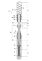
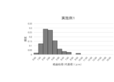
- FIG. 10 It is a partial vertical sectional view (cross-sectional view along the long axis direction of a guide wire 10) which shows the guide wire 10. It is a figure which shows the particle size distribution of Example 1.
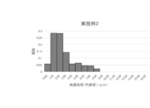
- FIG. It is a figure which shows the particle size distribution of Example 2.
- FIG. It is a figure which shows the particle size distribution of the comparative example 1.
- FIG. It is a figure which shows the particle size distribution of the comparative example 2.
- the direction in which the guide wire extends in a natural state is referred to as a "long axis direction".
- the direction in which the guide wire is separated or approaches the guide wire is defined as the "radial direction”.
- the rotation direction with the long axis direction of the guide wire as the reference axis is defined as the "circumferential direction”.
- the side of the guide wire that is inserted into the blood vessel is the tip side, and the end side opposite to the tip side is the base end side.
- the portion including a certain range from the tip (leading edge) in the long axis direction is referred to as the "tip portion”
- the portion including the fixed range in the long axis direction from the proximal end (most proximal end) is referred to as the "base end portion”. do.
- X to Y indicating a range includes X and Y and means "X or more and Y or less”.
- FIG. 1 is a vertical cross-sectional view of the guide wire 10.
- the guide wire 10 is inserted into a blood vessel and inserted into the lumen (guide wire lumen) of a therapeutic or diagnostic catheter, and is used to guide the catheter to a target site in the blood vessel.
- the guide wire 10 includes a core wire 20 extending in the axial direction, a coil 30 arranged at the tip of the core wire 20, and a tip-side coating layer (corresponding to a resin coating layer). It includes a 41, a tubular member 50 arranged on the base end side of the front end side covering layer 41, and a base end side covering layer 60 arranged on the base end portion of the core wire 20.
- the length of the guide wire 10 along the major axis direction is not particularly limited, but can be, for example, 200 to 5000 mm.
- the core wire 20 has a first wire 21 arranged on the distal end side in the major axis direction and a second wire 22 arranged on the proximal end side of the first wire 21.
- the first wire 21 and the second wire 22 are solid-phase bonded at the bonding portion 37 via the bonding surface d1.
- the joint portion 37 has a protruding portion 70 projecting radially outward from the outer surface of the core wire 20.
- the first wire 21 includes a tip portion 36 arranged on the tip end side of the first wire 21, a first outer diameter constant portion 34 arranged on the base end side of the tip end portion 36, and a tip portion 36 and a first outer diameter. It has a first tapered portion 35 arranged between the fixed portion 34 and the fixed portion 34.
- the tip portion 36 extends from the tip of the first wire 21 to the tip of the first tapered portion 35 and has a substantially constant outer diameter along the major axis direction.
- the first tapered portion 35 extends from the base end of the tip portion 36 to the tip end of the first outer diameter constant portion 34, and the outer diameter gradually increases along the long axis direction.
- the first outer diameter constant portion 34 extends from the base end of the first tapered portion 35 to the tip of the protrusion 70, and has a substantially constant outer diameter along the long axis direction.
- the outer diameter of the first outer diameter constant portion 34 is 0.6 mm to 0.8 mm.
- the second wire 22 includes a second outer diameter constant portion 38 arranged on the tip end side of the second wire 22, and a third outer diameter constant portion 40 arranged on the base end side of the second outer diameter constant portion 38. It has a second tapered portion 39 arranged between the second outer diameter constant portion 38 and the third outer diameter constant portion 40.
- the second outer diameter constant portion 38 extends from the base end of the protruding portion 70 to the tip end of the second tapered portion 39, and has a substantially constant outer diameter along the long axis direction.
- the outer diameter of the second constant outer diameter portion 38 is substantially equal to the outer diameter of the first constant outer diameter portion 34 of the first wire 21, and is 0.6 mm to 0.8 mm.
- the second tapered portion 39 extends from the base end of the second outer diameter constant portion 38 to the tip of the third outer diameter constant portion 40, and the outer diameter gradually increases along the long axis direction.
- the third outer diameter constant portion 40 extends from the base end of the second tapered portion 39 to the base end of the second wire 22, and has a substantially constant outer diameter along the long axis direction.
- the core wire 20 is formed by solid-phase bonding the first wire 21 and the second wire 22.
- the first wire 21 and the second wire 22 can be formed by grinding metal wires having a constant outer diameter.
- the outer diameter of the second wire 22 before grinding is larger than the outer diameter of the first wire 21 before grinding.
- the outer diameter (mm) at a position 150 mm from the joint surface d1 to the proximal end side is, for example, 115% or more of the outer diameter (mm) at 150 mm from the joint surface d1 to the tip end side.
- Both the first wire 21 and the second wire 22 have a substantially circular cross-sectional shape.
- the shapes of the first wire 21 and the second wire 22 are not limited to this.
- the first wire 21 and the second wire 22 have a second outer diameter constant portion 38 and a third outer diameter of the second wire 22 between the tip portion 36 of the first wire 21 and the first outer diameter constant portion 34.
- Another tapered portion or a constant outer diameter portion may be provided between the constant portion 40 and the constant portion 40.
- the cross-sectional shape of the tip portion 36 of the first wire may be rectangular.
- the first wire 21 and the second wire 22 are made of a Ni—Ti alloy. Since the Ni—Ti alloy has superelasticity, even when stress is applied and the alloy deforms to the plastic deformation region, it can easily be restored to its original shape after the stress is removed. As a result, the guide wire 10 is prevented from being plastically deformed and bent during use to reduce operability. Further, when the first wire 21 and the second wire 22 are made of the same material, the core wire 20 has a gradual change in physical properties from the first wire 21 including the joint portion 37 to the second wire 22, so that the joint portion is formed. It is easy to obtain the joint strength of 37.
- the plastic deformation at the time of solid phase bonding is similar between the first wire 21 and the second wire 22, and the shape of the joint portion 37 is the joint surface. Is almost symmetrical with the plane of symmetry. As a result, when the guide wire 10 is subjected to strong bending deformation, stress concentration on either the first wire 21 or the second wire 22 is relaxed, so that the bonding strength against bending deformation is improved.
- Ni—Ti alloy for example, the following formula (1):
- A is an unavoidable impurity.
- the joint portion 37 is a portion of the core wire 20 including the vicinity of the joint surface d1 and the joint surface d1 between the first wire 21 and the second wire 22.
- the joining portion 37 is formed by solid-phase joining the base end surface of the wire forming the first wire 21 and the tip end surface of the wire forming the second wire 22.
- Solid phase bonding is one of the methods for directly bonding two metal materials.
- the base metal is bonded by plastic flow without melting.
- Solid phase bonding is performed at a temperature below the melting point, and a molten portion called a nugget is not formed on the bonding surface. Therefore, it is possible to prevent the material properties near the joint surface from being significantly different from the material properties of the base metal. That is, in the core wire 20, by solid-phase bonding of the first wire 21 and the second wire 22, the change in material properties in the vicinity of the joint portion 37 when viewed along the long axis direction becomes small.
- Another method of directly joining two metals is melt joining.
- melt bonding a plurality of base metals are joined by heating, melting, and solidifying the base metal, so that a nugget is formed on the joint surface.
- the nugget and the metal near the joint surface are denatured from the base metal by the heat of fusion. Therefore, the material properties near the joint surface may be significantly different from the material properties of the base metal.
- Solid phase bonding and melt bonding can be distinguished by checking the presence or absence of nuggets on the bonding surfaces of the two metals with a scanning electron microscope.
- the method of solid-phase bonding between the first wire 21 and the second wire 22 is not particularly limited, and examples thereof include friction bonding, normal temperature pressure bonding, high temperature pressure bonding, explosion bonding, and electromagnetic pulse bonding.
- friction bonding normal temperature pressure bonding
- high temperature pressure bonding high temperature pressure bonding
- explosion bonding explosion bonding
- electromagnetic pulse bonding electromagnetic pulse bonding.
- the base end surface of the first wire 21 and the tip end surface of the second wire 22 are brought into pressure contact in a state of being abutted in the axial direction, and heat is applied to the contact portions of both wires.
- the temperature of the vicinity of the contact portion of the first wire 21 and the second wire 22 rises and softens, and at the same time, the first wire 21 and the second wire 22 are compressed in the major axis direction and plastically deformed.
- the metal material in the vicinity of the contact portion between the first wire 21 and the second wire 22 is extruded radially outward by compression, and an amount of burrs corresponding to the amount of deformation during plastic deformation is formed on the joint surface d1. ..
- the heat input is stopped after the contact portion has risen to an appropriate temperature, the temperature in the vicinity of the contact portion of the first wire 21 and the second wire 22 decreases, and solid-phase bonding is achieved.
- one of the first wire 21 and the second wire 22 is rotated so that the central axis serves as a rotation axis.
- the contact portion between the first wire 21 and the second wire 22 is energized to generate Joule heat.
- the amount of heat input can be controlled by adjusting the joining conditions such as pressure, rotation speed, current, and the time to apply them.
- a sufficient amount of heat input at the initial stage of bonding is required.
- the strength of the contact portion between the first wire 21 and the second wire 22 may decrease or melt due to the influence of heat. If the amount of heat input becomes too small, the contact portion between the first wire 21 and the second wire 22 is insufficiently softened and plastic deformation does not occur sufficiently, so that the joint strength is lowered.
- the base end portion of the first wire 21 and the tip end portion of the second wire 22 to be used in the joining step have substantially the same outer diameter by processing such as grinding.
- the positions of both wires are less likely to shift on the joint surface d1, so that the central axis of the core wire 20 (passes approximately the center of the cross section of the core wire 20 and is the long axis).
- the axis extending in the direction) is almost straight.
- the central axis of the core wire 20 substantially coincides with the central axis of the guide wire 10.
- the base end surface of the first wire 21 used in the joining process is substantially perpendicular to the central axis of the first wire 21.
- the tip surface of the second wire 22 used in the joining step is substantially perpendicular to the central axis of the second wire 22.
- the base end surface of the first wire 21 and the tip end surface of the second wire 22 can be easily formed.
- the base end surface of the first wire 21 and the tip surface of the second wire 22 to be used in the joining step may be inclined with respect to the surface perpendicular to the central axis of each wire, and may be concave or convex. good.
- the base end surface of the first wire 21 and the tip end surface of the second wire 22 are subjected to a treatment for removing deposits and oxide films existing on each end surface before performing the joining step.
- the treatment method include polishing and acid treatment.
- the joint portion 37 has a metal structure different from that of the first constant outer diameter portion 34 of the first wire 21 and the second constant outer diameter portion 38 of the second wire 22 adjacent to the joint portion 37 due to solid phase bonding.
- the metallographic structure observed in the first wire 21 and the second wire 22 before joining is a fibrous shape parallel to the major axis direction of each wire (an elliptical shape having the major axis direction of each wire as the major axis). ..
- the metal structure in the vicinity of the bonding surface d1 is remarkably miniaturized by the heat and pressure applied at the time of bonding, and a heat-affected zone is observed around the metal structure.
- the fibrous metal structure changes or disappears in the direction along the direction in which the burrs are extruded (outer in the radial direction) in the vicinity of the joint surface d1.
- the orientation of the fibrous metal structure is the first wire 21 or the second wire 22.
- the portion changing from the direction parallel to the long axis direction of is referred to as the joint portion 37.
- the length of the joint portion 37 along the major axis direction is equal to the length of the heat-affected zone along the major axis direction.
- the joint surface d1 is a surface where the base end surface of the first wire 21 and the tip end surface of the second wire 22 are in contact with each other.
- the position is referred to as the joint surface.
- the central position of the bonding portion 37 is defined as the bonding surface d1 in the long axis direction of the core wire 20.
- the bonding surface d1 formed by solid phase bonding is substantially perpendicular to the central axis of the core wire 20. Further, it is preferable that the central axis of the first wire 21 and the central axis of the second wire 22 substantially coincide with each other on the joint surface d1 of the guide wire 10.
- the joint surface d1 may be inclined with respect to a surface perpendicular to the central axis of the core wire 20, and may be concave or convex.
- the metallographic structure of the joint surface d1 and its vicinity greatly affects the joint strength between the first wire 21 and the second wire 22.
- the metal structure in the vicinity of the bonding surface d1 is preferably uniform.
- the size of the crystal grains of the metal structure correlates with the hardness of the metal, and the smaller the crystal grains, the higher the hardness. Therefore, if the uniformity of the metal structure is low, local stress concentration is likely to occur on the joint surface d1 due to the difference in hardness, and the joint strength is lowered.
- the core wire 20 bonded in a solid phase may adjust the height of burrs generated at the joint portion 37 by mechanical polishing.
- the core wire 20 having a low uniformity of the metal structure in the vicinity of the joint surface d1 has a non-uniform hardness distribution on the joint surface d1, unintended irregularities are likely to occur on the outer surface after mechanical polishing.
- Such irregularities on the outer surface cause local stress concentration, which causes a decrease in the joint strength of the joint surface d1.
- the unevenness of the outer surface has a large effect on the joint strength.
- the uniformity of the metal structure can be evaluated by the particle size distribution of the crystal grains of the metal structure.
- the number of crystal grains contained in each section is divided into several sections between the maximum diameter and the minimum diameter for the crystal grains existing in an arbitrary area (measurement target area). It is obtained by measuring the area and area.
- the particle size distribution in the vicinity of the joint surface d1 is obtained by microscopically observing the vertical cross section including the intersection of the central axis of the core wire 20 and the joint surface d1 using a scanning electron microscope (magnification of about 5000 times).
- the crystal grain size of the crystal grains existing in the measurement target region of the obtained image is expressed as a frequency distribution based on the number.
- each crystal grain size is calculated from the image showing the grain boundary of the crystal grain using the crystal orientation / grain boundary microstructure automatic analyzer (OIM), and each crystal grain is a true sphere, that is, a two-dimensional plane. Calculated as the diameter assuming that the shape is a perfect circle.
- the measurement target region of the particle size distribution is 0.075 mm ⁇ 0.075 mm centered on the intersection of the central axis of the core wire 20 and the joint surface d1.
- the interval of the crystal particle size in the particle size distribution is 1.00 ⁇ m.
- the crystal particle size corresponding to the median value of each section is used as the representative diameter of the section.
- the frequency of crystal grains having a representative diameter of 0.05 ⁇ m is such that the number of crystal grains in which the measured value of the crystal grain size exceeds 0 ⁇ m and is 1.00 ⁇ m or less in the measurement target region is the number of all crystal grains. Shows the ratio to.
- the size of the crystal grains of the metal structure correlates with the hardness. Therefore, the uniformity of the metallographic structure can also be evaluated by the hardness distribution.
- the hardness of the metal in the vicinity of the bonding surface d1 is uniform.
- the hardness is a value obtained by measuring the test force and the indentation depth at the time of indentation indentation and converting the indentation hardness obtained from the load unloading curve into a Vickers hardness conversion value.
- the hardness of the joint surface d1 is two points at a position 0.0625 mm radially outward from the intersection and the joint surface d1 from the intersection and the vertical cross section including the intersection of the central axis of the core wire 20 and the joint surface d1. , The average value of 5 points measured at 2 points at a position of 0.125 mm. The hardness shall be obtained up to the second decimal place.
- the core wire 20 extends from the first outer diameter constant portion 34 of the first wire 21 to the second outer diameter constant portion 38 of the second wire 22.
- the change in hardness along the long axis direction is small. Therefore, it is preferable that the metal structure near the joint surface d1 has an appropriately large crystal grain size.
- the metal structure near the bonding surface d1 is recrystallized by heat and pressure during solid phase bonding and becomes finer. At the same time, the hardness of the joint portion 37 located around the joint surface d1 becomes lower than the hardness of the first wire 21 and the second wire 22 before solid-phase bonding due to the influence of heat.
- the change in hardness of the joint portion 37 becomes large in the vicinity of the joint surface d1, and the stress is locally concentrated on the joint surface d1 and the boundary point of the hardness change. Is likely to occur.
- the change in hardness of the core wire 20 from the first constant outer diameter portion 34 of the first wire 21 to the second constant outer diameter portion 38 of the second wire 22 along the major axis direction becomes large, and the core wire 20 is joined in the tensile test. It becomes difficult to improve the strength.
- the frequency of the most frequent particle size when the interval of the crystal grain size is 1 ⁇ m is 25% or more, more preferably 28% or more. be.
- the most frequent particle size is a representative diameter (mode diameter) of the section having the highest frequency in the particle size distribution.
- the joint surface d1 has a high uniformity of metal structure. As a result, local stress concentration is less likely to occur on the joint surface d1 due to differences in physical properties, and the joint strength is improved.
- the upper limit of the frequency of the most frequent particle size is 100% or less, but usually 40% or less.
- the representative diameter is (most frequent particle size ( ⁇ m) -1 ⁇ m) or more (most frequent particle size ( ⁇ m)). ) + 1 ⁇ m) or less is preferably 60% or more, and more preferably 62% or more. That is, the total frequency of the frequency of the section having the most frequent particle size and the frequency of the two sections adjacent to the section having the most frequent particle size is preferably 60% or more, and more preferably 62% or more. preferable.
- the joint surface d1 having such a particle size distribution has a higher uniformity of metal structure.
- the joint surface d1 is less likely to cause local stress concentration due to the difference in physical properties, and the effect of improving the joint strength is further increased. Further, in the number-based particle size distribution of the crystal grains of the metal structure near the joint surface d1, the upper limit of the frequency of the most frequent particle size is 100% or less, but usually 75% or less.
- the mode particle size is preferably 2.50 ⁇ m or more when the interval of the crystal grain size is 1 ⁇ m.
- the upper limit of the most frequent particle size is preferably 5.50 ⁇ m or less, and more preferably 3.50 ⁇ m or less. Since the hardness of the joint surface d1 is not significantly reduced by reducing the proportion of coarse crystal grains contained in the joint surface d1, the joint surface d1 can obtain high joint strength.
- the standard deviation of hardness on the joint surface d1 is preferably 10.00 or less, and more preferably 9.00 or less.
- the standard deviation of hardness is an unbiased standard deviation of 5 points measured on the joint surface d1 as a sample, and is obtained up to the second decimal place.
- the joint surface d1 has a high uniformity of metal structure. As a result, local stress concentration is less likely to occur on the joint surface d1 due to differences in physical properties, and the joint strength is improved. Further, the joint surface d1 has improved workability during mechanical polishing.
- the lower limit of the standard deviation of hardness on the joint surface d1 is 0, but it is usually 4.00 or more.
- the metallographic structure of the joint surface d1 as described above can be obtained by appropriately controlling the amount of heat input, the amount of heat radiation, and the amount of deformation at the contact portion between the first wire 21 and the second wire 22 when performing solid phase bonding. Can be done.
- the amount of heat input and the amount of heat radiation affect the degree of recrystallization and growth of crystal grains in the vicinity of the joint surface d1.
- the amount of deformation during plastic deformation affects the degree to which fine crystal grains generated by solid-phase bonding remain in the vicinity of the bonding surface d1.
- the amount of heat input, the amount of heat radiation, and the amount of deformation can be controlled by adjusting various conditions for solid phase bonding.
- Joule heat When Joule heat is used for heat input to the contact portion between the first wire 21 and the second wire 22 in solid-phase bonding, Joule heat is a function of resistance, current value, and energization time, so the amount of heat input and heat dissipation , The amount of deformation can be controlled by the current value and the energization time.
- deformation starts from the start of energization. It is important to control the current value in the previous fixed time.
- the current value in a certain period of time from the start of energization to the start of deformation affects both the amount of heat input and the amount of heat radiation, and as a result, affects the amount of deformation. From the transition of the amount of deformation, it was estimated that the time to reach the maximum temperature was 5 ms from the start of energization.
- the specific current value is appropriately set in consideration of the outer diameter, composition, etc. of the first wire and the second wire, but the current value at 5 ms from the start of energization is preferably 10 A to 1000 A. It is preferably more than 75A and less than 300A.
- the core wire 20 can obtain a metal structure having a high bonding strength on the bonding surface d1 between the first wire 21 and the second wire 22.
- the pressure at the time of pressure contact between the base end surface of the first wire 21 and the tip end surface of the second wire 22 is determined. For example, it is 50 MPa to 1000 MPa. The pressure may be increased or decreased during the joining process as needed.
- the amount of deformation is preferably 0.80 mm or more, and more preferably 1.00 mm or more.
- the upper limit of the amount of deformation is not particularly limited, but is, for example, 1.50 mm or less.
- the amount of deformation is the amount of displacement of the lengths of the first wire 21 and the second wire 22 in the major axis direction before and after solid phase bonding.
- the amount of deformation is small, the hardness of the joint surface d1 tends to increase locally due to the residual of extremely fine crystal grains generated by solid phase bonding on the joint surface d1.
- the amount of heat is increased in order to increase the amount of deformation, the hardness of the joint portion 37 tends to decrease due to the influence of heat.
- the core wire 20 has a protruding portion 70 formed by mechanically polishing the burr generated on the joint surface d1 at the joint portion 37.
- the protruding portion 70 projects radially outward from the outer surface of the core wire 20. That is, the outer diameter of the protruding portion 70 is the outer diameter of the first outer diameter constant portion 34 of the first wire 21 and the outer diameter of the second outer diameter constant portion 38 of the second wire 22 arranged in the vicinity of the joint portion 37. Larger than the diameter.
- the joint strength of the first wire 21 and the second wire 22 is improved because the area of the joint surface d1 is increased by forming the protruding portion 70 at the joint portion 37 of both wires.
- the flexural rigidity of the guide wire 10 can be expressed by Young's modulus and the moment of inertia of area.
- the hardness of the joint portion 37 is lower than that of the first constant outer diameter portion of the first wire 21 and the second constant outer diameter portion of the second wire 22 arranged in the vicinity of the joint portion 37 due to solid phase bonding. There is.
- the guide wire 10 is Flexural rigidity is reduced at the joint portion 37. Therefore, when the guide wire 10 receives a compressive force in the long axis direction, only the joint portion 37 is easily deformed.
- the joint portion 37 has a larger outer diameter than the first constant outer diameter portion 34 and the second constant outer diameter portion 38 of the second wire 22, and the moment of inertia of area becomes larger.
- the guide wire 10 having the protruding portion 70 can suppress a decrease in bending rigidity at the joint portion 37 and prevent only the joint portion 37 from being deformed.
- the guide wire 10 can efficiently transmit the torque and the pushing force applied to the base end portion of the second wire 22 by the operator to the first wire 21.
- the outer shape of the protruding portion 70 is substantially trapezoidal in the vertical cross-sectional view of the guide wire 10. Further, the joint surface d1 between the first wire 21 and the second wire 22 is located substantially at the center of the upper bottom of the trapezoid. That is, the joint surface d1 between the first wire 21 and the second wire 22 is located at the maximum outer diameter portion of the protruding portion 70.
- the outer shape of the protruding portion 70 in the vertical cross-sectional view of the guide wire 10 is not limited to the trapezoidal shape, and may be an arc shape or a polygonal shape. Further, the trapezoidal upper base of the protruding portion 70 observed in the vertical cross-sectional view of the guide wire 10 is not limited to a straight line, but may be a curved line.
- the height of the protruding portion 70 is the distance between the maximum outer diameter portion of the protruding portion and the outer surface of the first constant outer diameter portion 34 of the first wire 21 or the second constant outer diameter portion 38 of the second wire 22.
- the height of the protruding portion 70 in the vertical cross-sectional view of the guide wire 10 is trapezoidal, the height of the protruding portion 70 is outside the first wire 21 or the second wire 22 parallel to the upper bottom of the trapezoid and the upper bottom of the trapezoid.
- the distance from the surface is preferably 0.001 mm to 0.200 mm, more preferably 0.020 mm to 0.100 mm.
- the maximum outer diameter (mm) of the first wire 21 excluding the protrusion 70 is 90% to 100% of the maximum outer diameter (mm) of the protrusion 70, and the maximum of the second wire 22 excluding the protrusion 70.
- the outer diameter (mm) is 100% to 120% of the maximum outer diameter (mm) of the protruding portion 70.
- the coil 30 is arranged so as to cover a certain range of the tip end portion of the first wire 21.
- the coil 30 is formed by spirally winding a wire around the first wire 21 along the circumferential direction of the first wire 21. It is preferable that the coil 30 and the outer surface of the first wire 21 are in close contact with each other. Further, it is preferable that the coil 30 is formed so as to have a gap between adjacent windings without applying an external force.
- the coil 30 may be formed so as not to have a gap between adjacent windings without applying an external force.
- the wire forming the coil 30 is preferably made of a material having X-ray impermeable properties.
- the material having X-ray impermeable properties include noble metals such as gold, platinum and tungsten, and metal materials such as alloys containing these.
- the tip of the coil 30 is fixed to the tip of the first wire 21 by the fixing member 31.
- the base end of the coil 30 is fixed to the first tapered portion 35 of the first wire 21 by the fixing member 32.
- the material forming the fixing member include an adhesive, a brazing material, and a solder.
- the tip-side coating layer 41 is made of a resin material and is formed so as to cover the tip of the core wire 20 including the coil 30.
- the tip portion of the tip-side covering layer 41 preferably has a rounded shape so as not to damage the blood vessel wall. Further, the base end portion of the front end side covering layer 41 is located at the first outer diameter constant portion 34 of the core wire 20 (first wire 21).
- the tip side coating layer 41 is preferably made of a highly flexible resin material. As a result, the tip side of the guide wire 10 becomes flexible, and it is possible to prevent damage to the inner wall of the blood vessel.
- the resin material forming the tip side coating layer 41 include polyolefins such as polyethylene and polypropylene, polyvinyl chloride, polyester (PET, PBT, etc.), polyamide, polyimide, polystyrene, polycarbonate, silicone resin, and fluororesin (PTFE). , ETFE, PFA, etc.), urethane resins, or composite materials thereof, various rubber materials such as latex rubber, silicone rubber, or composite materials in which two or more of these are combined. Among the above materials, it is more preferable to use a urethane resin.
- the thickness of the front end side coating layer 41 is not particularly limited, but is preferably 5 ⁇ m to 500 ⁇ m, for example.
- the tip-side coating layer 41 is not limited to a single-layer structure, and a plurality of layers may be laminated.
- the tip side coating layer 41 is preferably covered with a hydrophilic coating layer (not shown).
- the material for forming the hydrophilic coating layer is not particularly limited, but for example, a cellulose-based polymer substance, a polyethylene oxide-based polymer substance, or a maleic anhydride-based polymer substance (for example, a methyl vinyl ether-maleic anhydride copolymer).
- a maleic anhydride copolymers eg, block copolymers of polyacrylamide, polyglycidyl methacrylate-dimethylacrylamide (PGMA-DMAA)), water-soluble nylon, polyvinyl alcohol, polyvinylpyrrolidone, etc.
- PGMA-DMAA polyglycidyl methacrylate-dimethylacrylamide
- Known hydrophilic substances such as.
- the thickness of the hydrophilic coating layer is not particularly limited, but is preferably 0.1 ⁇ m to 100 ⁇ m, for example.
- the tubular member 50 is a tubular member arranged in the first outer diameter constant portion 34 of the first wire 21.
- the tip of the tubular member is in contact with the base end of the tip-side covering layer 41, and the base end of the tip-side covering layer 41 has entered the lumen of the tubular member 50.
- the base end portion of the tubular member 50 is fixed to the first wire 21 by the fixing member 51.
- the base end portion of the tubular member 50 has a tapered portion 52 whose outer diameter gradually decreases toward the base end side.
- the fixing member 51 located on the proximal end side of the tubular member 50 is formed in a tapered shape so as to be continuous with the tapered portion 52 of the tubular member 50.
- the tubular member 50 is preferably made of metal.
- the metal forming the tubular member 50 include stainless steel, superelastic alloys, cobalt-based alloys, precious metals such as gold, platinum, and tungsten, or alloys containing these (platinum-iridium alloy).
- the base end covering layer 60 is formed so as to cover at least a part of the outer surface of the second wire 22.
- the base end covering layer 60 includes an inner layer 61 that covers the outer surface of the second wire 22, an outer layer 62 that covers the outer surface of the inner layer, and a striatum 63 that is spirally wound around the outer surface of the outer layer 62. Have.
- Examples of the material forming the inner layer 61 and the outer layer 62 include fluorine-based resins such as polytetrafluoroethylene (PTFE) and tetrafluoroethylene-ethylene copolymer (ETFE). Further, the inner layer 61 and the outer layer 62 may contain a pigment.
- fluorine-based resins such as polytetrafluoroethylene (PTFE) and tetrafluoroethylene-ethylene copolymer (ETFE).
- PTFE polytetrafluoroethylene
- ETFE tetrafluoroethylene-ethylene copolymer
- the base end side coating layer 60 is not limited to the above-described configuration, and may be composed of, for example, one layer.
- the striatum 63 is a member that is spirally wound along the circumferential direction of the second wire 22 and has a convex shape from the outer surface of the outer layer 62 toward the outside in the radial direction.
- the striatum 63 is formed so that adjacent windings are separated from each other. With such a striatum 63, the outer surface of the second wire 22 has a plurality of convex portions and concave portions formed between adjacent convex portions.
- the striatum 63 is preferably formed of resin.
- a fluororesin such as polytetrafluoroethylene (PTFE) or tetrafluoroethylene-hexafluoropropylene copolymer (FEP) can be used.
- PTFE polytetrafluoroethylene
- FEP tetrafluoroethylene-hexafluoropropylene copolymer
- the striatum 63 may contain a pigment.
- Examples of the method of spirally winding the striatum 63 around the outer surface of the outer layer 62 include dipping and spotting.
- the second wire 22 in which the masking tape is spirally wound around the portion on the outer layer 62 where the recess is to be formed is immersed in a solution containing the resin forming the striatum 63, dried, and then the masking tape is used. It is a method of removing.
- a resin forming a striatum 63 dissolved in a solvent or in a molten state is linearly extruded on the outer surface of the outer layer 62 of the second wire 22 that moves in the long axis direction while rotating. The method.
- the striatum 63 may be fixed to the outer surface of the outer layer 62 by being wound around the outer surface of the outer layer 62 and then heated to near the melting point temperature of the striatum 63.
- the resin is spirally applied to the outer surface of the outer layer 62 of the second wire 22, and a linear body 63 which is a convex portion extending radially outward from the outer surface of the outer layer 62 is formed.
- each convex portion has a top portion which is the most protruding position on the radial outer side of the convex portion, a tip side end portion located on the tip end side from the top portion, and a proximal end side from the top portion.
- the contour of the outer surface of the convex portion is a smooth arc shape connecting the distal end side end portion, the top portion, and the proximal end side end portion.
- the contour of the outer surface of the convex portion in the vertical cross-sectional view of the second wire 22 is not limited to an arc, and may be an elliptical arc, a triangle, or a rectangle.
- the height of the convex portion is preferably 0.001 mm to 0.100 mm.
- the height of the convex portion means the length of a perpendicular line drawn from the top of the convex portion to the outer surface of the outer layer 62 in the vertical cross-sectional view of the second wire 22.
- Example 1 (Preparation of test piece) Two Ni—Ti alloy wires having an outer diameter of 0.68 to 0.72 mm were prepared, and the ends of the wires were solid-phase bonded to each other.
- the composition of the Ni—Ti alloy was 55-56% by weight for Ni and Ti for the rest.
- the two wires were arranged in the joining device in an axially aligned state, and each wire was clamped and fixed. Next, the end faces of the two wires were brought into pressure contact with each other to energize the joining device.
- the two wires were solid-phase bonded by being softened and plastically deformed by the heat generated at the contact portion between the two wires.
- the joined wires were plastically deformed by compression to form burrs protruding outward in the radial direction at the positions where the two wires were in contact with each other.
- the burrs were mechanically polished to obtain a wire having an outer diameter of a protruding portion of 0.62 mm to 0.72 mm.
- the outer diameter was measured using a thickness gauge.
- the obtained wire was used as a test piece for the following evaluation.
- the current value at 5 ms from the start of energization was 200 A.
- the current value at 5 ms from the start of energization was 75 to 300 A.
- Example 2 Two Ni—Ti alloy wires having an outer diameter of 0.68 to 0.72 mm were prepared, and the ends of the wires were solid-phase bonded to each other.
- the composition of the Ni—Ti alloy was 55-56% by weight for Ni and Ti for the rest.
- the two wires were arranged in the joining device in an axially aligned state, and each wire was clamped and fixed. Next, the end faces of the two wires were brought into pressure contact with each other to energize the joining device.
- the two wires were solid-phase bonded by being softened and plastically deformed by the heat generated at the contact portion between the two wires.
- the joined wires were plastically deformed by compression to form burrs protruding outward in the radial direction at the positions where the two wires were in contact with each other.
- the burrs were mechanically polished to obtain a wire having an outer diameter of a protruding portion of 0.62 mm to 0.72 mm.
- the outer diameter was measured using a thickness gauge.
- the obtained wire was used as a test piece for the following evaluation. In Example 2, the current value at 5 ms from the start of energization was 100 A.
- the joined wires were plastically deformed by compression to form burrs protruding outward in the radial direction at the positions where the two wires were in contact with each other.
- the burrs were mechanically polished to obtain a wire having an outer diameter of a protruding portion of 0.62 mm to 0.72 mm.
- the outer diameter was measured using a thickness gauge.
- the obtained wire was used as a test piece for the following evaluation.
- the current value at 5 ms from the start of energization was 300 A.
- the joined wires were plastically deformed by compression to form burrs protruding outward in the radial direction at the positions where the two wires were in contact with each other.
- the burrs were mechanically polished to obtain a wire having an outer diameter of a protruding portion of 0.62 mm to 0.72 mm.
- the outer diameter was measured using a thickness gauge.
- the obtained wire was used as a test piece for the following evaluation.
- the current value at 5 ms from the start of energization was 75 A.
- the joint strength of the test piece including the joint was determined by a tensile test using an autograph (manufactured by Shimadzu Corporation). The test piece was fixed to the chuck up and down so that the joint was located in the center between the chucks. The upper part of the test piece was pulled, and the maximum test force until the test piece broke was defined as the joint strength of the test piece. The distance between chucks (distance between original reference points) was 8 mm, and the test speed was 5 mm / min.
- the hardness of the test piece was determined by a micro-indentation test defined in the international standard ISO14577-1. After embedding the joint surface of the test piece and the portion including the vicinity thereof with resin, the test piece was cut and polished to expose the central axis of the test piece or the vertical cross section including the vicinity of the central axis. Using a dynamic ultra-micro hardness tester (DUH-211S, manufactured by Shimadzu Corporation), indenters are applied to a predetermined position on the vertical cross section until the test force reaches 65 ⁇ N according to ISO14577-1 (instrumentation indentation hardness test).
- Table 1 shows the amount of deformation, bonding strength, most frequent particle size, frequency of crystal grains having the most frequent particle size, and representative diameter of Examples 1 and 2 and Comparative Examples 1 and 2 (most frequent particle size ( ⁇ m)-. It shows the frequency, hardness, and standard deviation of the crystal grains having a crystal grain size of 1 ⁇ m) or more (most frequent particle size ( ⁇ m) + 1 ⁇ m) or less.
- 2 to 5 are number-based particle size distributions of Examples 1 and 2 and Comparative Examples 1 and 2, respectively. The interval of the crystal particle size in the particle size distribution was set to 1 ⁇ m, and the representative diameter of the crystal particle size corresponding to the median value of each section was shown on the horizontal axis.
- Example 1 in which the mode particle size is 2.50 ⁇ m or more and the standard deviation of the hardness on the joint surface is 10.00 or less, the joint strength is further improved.
- the bonding strength is high.
- torque transmission will be improved and fatigue strength will be improved by relaxing stress concentration.
Landscapes
- Engineering & Computer Science (AREA)
- Mechanical Engineering (AREA)
- Health & Medical Sciences (AREA)
- Life Sciences & Earth Sciences (AREA)
- Chemical & Material Sciences (AREA)
- Anesthesiology (AREA)
- Veterinary Medicine (AREA)
- Heart & Thoracic Surgery (AREA)
- Hematology (AREA)
- Animal Behavior & Ethology (AREA)
- General Health & Medical Sciences (AREA)
- Public Health (AREA)
- Biomedical Technology (AREA)
- Pulmonology (AREA)
- Materials Engineering (AREA)
- Biophysics (AREA)
- Metallurgy (AREA)
- Organic Chemistry (AREA)
- Media Introduction/Drainage Providing Device (AREA)
- Pressure Welding/Diffusion-Bonding (AREA)
Abstract
接合強度が向上したガイドワイヤを提供する。第1ワイヤと第2ワイヤとを固相接合させたガイドワイヤであって、第1ワイヤおよび第2ワイヤはNi-Ti系合金からなり、第1ワイヤと第2ワイヤとの接合面の金属組織の結晶粒の個数基準粒径分布において、結晶粒径の区間を1μmとしたとき、最頻粒径を有する結晶粒の頻度は25%以上であり、代表径が(最頻粒径(μm)-1μm)以上(最頻粒径(μm)+1μm)以下の結晶粒径を有する結晶粒の頻度は60%以上である、ガイドワイヤ。
Description
本発明は、ガイドワイヤに関する。
ガイドワイヤは、血管内治療を行うためのカテーテルやステントを目的の位置まで誘導するために血管内に挿入する長尺状の医療器具である。
ガイドワイヤは、血管の複雑な湾曲部や分岐部を進み、狭窄部を通過する必要がある。そのため、ガイドワイヤは、血管内に挿入される側(先端側)では血管選択性や安全性の向上のために曲げ剛性が低く、術者が操作する側(基端側)では押し込み性やトルク伝達性の確保のために曲げ剛性が高いことが求められる。そこで、先端側と基端側とが異なる特性を有するように、太さや材料特性が異なる金属からなるワイヤ同士を接合して1本のコアワイヤを形成したガイドワイヤが知られている(例えば、特許文献1)。
ガイドワイヤは、血管内を進む際には血管の形状に合わせて湾曲し、狭窄部通過の際には術者による押し引き操作や回転操作を受ける。そのため、金属からなるワイヤを接合したガイドワイヤは、接合部において十分な接合強度を有する必要がある。接合強度が不十分であると、ガイドワイヤは、血管内で使用中に、接合部において折れ曲がったりするリスクがある。
本発明は、上述の課題を解決するためになされたものであり、接合強度が向上したガイドワイヤを提供することを目的とする。
本発明は、第1ワイヤと第2ワイヤとを固相接合させたガイドワイヤであって、第1ワイヤおよび第2ワイヤはNi-Ti系合金からなり、第1ワイヤと第2ワイヤとの接合面の金属組織の結晶粒の個数基準粒径分布において、結晶粒径の区間を1μmとしたとき、最頻粒径の頻度は25%以上であり、代表径が(最頻粒径(μm)-1μm)以上(最頻粒径(μm)+1μm)以下の頻度は60%以上である、ガイドワイヤである。
本発明によれば、第1ワイヤと第2ワイヤとを接合した接合部を有するガイドワイヤにおいて、接合部の接合強度が向上する。そのため、ガイドワイヤは、血管内において折れ曲がったりするリスクを低減できる。
以下、添付した図面を参照して、本発明の実施の形態を説明する。なお、本発明は、以下の実施の形態のみには限定されない。なお、図面の説明において、同一の要素には同一の符号を付し、重複する説明を省略する。また、図面の寸法比率は、説明の都合上誇張されており、実際の比率とは異なる場合がある。
本明細書の説明では、自然状態(外力を付加せず、真っ直ぐな状態)でガイドワイヤが延びている方向を「長軸方向」とする。ガイドワイヤの長軸方向を基準軸としたガイドワイヤの横断面(軸直交断面)において、ガイドワイヤに対して離間または接近する方向を「径方向」とする。ガイドワイヤの長軸方向を基準軸にした回転方向を「周方向」とする。また、ガイドワイヤにおいて血管内に挿入される側を先端側とし、先端側と反対の端部側を基端側とする。また、先端(最先端)から長軸方向における一定の範囲を含む部分を「先端部」とし、基端(最基端)から長軸方向における一定の範囲を含む部分を「基端部」とする。
本明細書において、範囲を示す「X~Y」は、XおよびYを含み、「X以上Y以下」を意味する。
<ガイドワイヤ>
図1は、ガイドワイヤ10の縦断面図である。
図1は、ガイドワイヤ10の縦断面図である。
ガイドワイヤ10は、血管内に挿入されて、治療用または診断用のカテーテルの内腔(ガイドワイヤルーメン)に挿通された状態で、当該カテーテルを血管内の目的部位へ導くために用いられる。図1に示すように、第1実施形態に係るガイドワイヤ10は、軸方向に延伸するコアワイヤ20と、コアワイヤ20の先端部に配置されたコイル30および先端側被覆層(樹脂被覆層に相当)41と、先端側被覆層41の基端側に配置された筒状部材50と、コアワイヤ20の基端部に配置された基端側被覆層60とを備えている。
ガイドワイヤ10の長軸方向に沿う長さは、特に限定されないが、例えば、200~5000mmとすることができる。
(コアワイヤ)
図1に示すように、コアワイヤ20は、長軸方向において先端側に配置された第1ワイヤ21と、第1ワイヤ21の基端側に配置された第2ワイヤ22と、を有する。第1ワイヤ21と第2ワイヤ22とは、接合部37において接合面d1を介して固相接合されてなる。接合部37は、コアワイヤ20の外表面から径方向外側に向かって突出した突出部70を有する。
図1に示すように、コアワイヤ20は、長軸方向において先端側に配置された第1ワイヤ21と、第1ワイヤ21の基端側に配置された第2ワイヤ22と、を有する。第1ワイヤ21と第2ワイヤ22とは、接合部37において接合面d1を介して固相接合されてなる。接合部37は、コアワイヤ20の外表面から径方向外側に向かって突出した突出部70を有する。
第1ワイヤ21は、第1ワイヤ21の先端側に配置された先端部36と、先端部36の基端側に配置された第1外径一定部34と、先端部36と第1外径一定部34との間に配置された第1テーパー部35と、を有する。先端部36は、第1ワイヤ21の先端から第1テーパー部35の先端まで延び、長軸方向に沿ってほぼ一定の外径を有する。第1テーパー部35は、先端部36の基端から第1外径一定部34の先端まで延び、長軸方向に沿って外径が漸増している。第1外径一定部34は、第1テーパー部35の基端から突出部70の先端まで延び、長軸方向に沿ってほぼ一定の外径を有する。第1外径一定部34の外径は、0.6mm~0.8mmである。
第2ワイヤ22は、第2ワイヤ22の先端側に配置された第2外径一定部38と、第2外径一定部38の基端側に配置された第3外径一定部40と、第2外径一定部38と第3外径一定部40との間に配置された第2テーパー部39と、を有する。第2外径一定部38は、突出部70の基端から第2テーパー部39の先端まで延び、長軸方向に沿ってほぼ一定の外径を有する。第2外径一定部38の外径は、第1ワイヤ21の第1外径一定部34の外径とほぼ等しく、0.6mm~0.8mmである。第2テーパー部39は、第2外径一定部38の基端から第3外径一定部40の先端まで延び、長軸方向に沿って外径が漸増している。第3外径一定部40は、第2テーパー部39の基端から第2ワイヤ22の基端まで延び、長軸方向に沿ってほぼ一定の外径を有する。
コアワイヤ20は、第1ワイヤ21と第2ワイヤ22とを固相接合して形成される。第1ワイヤ21および第2ワイヤ22は、一定の外径を有する金属製のワイヤをそれぞれ研削することで形成できる。研削前の第2ワイヤ22の外径は、研削前の第1ワイヤ21の外径よりも大きい。コアワイヤ20は、外径の異なる2本のワイヤを研削した後に接合して形成することにより、1本のワイヤを研削して形成した場合と比較して、研削が必要な長さが短くなる。したがって、外径の異なる2本のワイヤを接合することによって、先端側の曲げ剛性が低い部分と基端側の曲げ剛性が高い部分とを備えたコアワイヤ20を容易に製造できる。コアワイヤ20において、接合面d1から基端側に150mmの位置における外径(mm)は、接合面d1から先端側に150mmにおける外径(mm)の例えば115%以上である。
第1ワイヤ21および第2ワイヤ22は、いずれもほぼ円形の横断面形状を有する。なお、第1ワイヤ21および第2ワイヤ22の形状はこれに限定されない。例えば、第1ワイヤ21および第2ワイヤ22は、第1ワイヤ21の先端部36と第1外径一定部34との間、第2ワイヤ22の第2外径一定部38と第3外径一定部40との間に、他のテーパー部や外径一定部を有してもよい。また、第1ワイヤの先端部36の横断面形状は、矩形としてもよい。
第1ワイヤ21および第2ワイヤ22は、Ni-Ti系合金で形成される。Ni-Ti系合金は、超弾性を有するため、応力が負荷されて塑性変形領域まで変形した場合でも、応力を除荷した後に元の形状に復元しやすい。これにより、ガイドワイヤ10は、使用中に、塑性変形して折れ曲がった状態となって操作性が低下することが抑制される。また、第1ワイヤ21と第2ワイヤ22とが同種素材であると、コアワイヤ20は、接合部37を含む第1ワイヤ21から第2ワイヤ22にかけての物性の変化が緩やかとなるため、接合部37の接合強度が得られやすい。また、第1ワイヤ21と第2ワイヤ22の物性が類似しているため、固相接合時の塑性変形が第1ワイヤ21と第2ワイヤ22とで類似し、接合部37の形状が接合面を対称面としてほぼ対称になる。これにより、ガイドワイヤ10は、強い曲げ変形を受けた際、第1ワイヤ21または第2ワイヤ22のいずれか一方への応力集中が緩和されるため、曲げ変形に対する接合強度が向上する。
Ni-Ti系合金としては、例えば、下記式(1):

前記式(1)において、Aは、不可避不純物であり、
x、yおよびaは、重量%の値を表し、この際、30≦x≦70、30≦y≦70および0≦a≦1であり、x+y+a=100である;で表される合金である。より好ましくは、式(1)において、40≦x≦60、40≦y≦60および0≦a≦1であり、x+y+a=100である。
x、yおよびaは、重量%の値を表し、この際、30≦x≦70、30≦y≦70および0≦a≦1であり、x+y+a=100である;で表される合金である。より好ましくは、式(1)において、40≦x≦60、40≦y≦60および0≦a≦1であり、x+y+a=100である。
接合部37は、コアワイヤ20のうち、第1ワイヤ21と第2ワイヤ22との接合面d1および接合面d1の近傍を含む部分である。接合部37は、第1ワイヤ21を形成するワイヤの基端面と第2ワイヤ22を形成するワイヤの先端面とを固相接合することによって形成される。
固相接合は、2つの金属材料を直接的に接合する方法のひとつである。固相接合では、母材金属は、溶融せずに塑性流動により接合する。固相接合は、融点以下の温度で行われ、接合面にナゲットと呼ばれる溶融部が形成されることがない。そのため、接合面近傍の材料特性が母材の材料特性と大きく異なることを抑制できる。すなわち、コアワイヤ20は、第1ワイヤ21と第2ワイヤ22とを固相接合することで、長軸方向に沿ってみたときの接合部37近傍での材料特性の変化が小さくなる。2つの金属を直接的に接合する他の方法としては、溶融接合がある。溶融接合は、母材金属の加熱溶融・凝固により複数の母材金属を接合するため、接合面にナゲットが形成される。ナゲットおよび接合面近傍の金属は、溶融熱によって母材から変性が生じる。このため、接合面近傍の材料特性は、母材の材料特性と大きく異なってしまうことがある。固相接合と溶融接合とは、走査電子顕微鏡で2つの金属の接合面のナゲットの有無を確認することによって判別可能である。
第1ワイヤ21と第2ワイヤ22とを固相接合する方法は、特に限定されないが、例えば、摩擦接合、常温圧力接合、高温圧力接合、爆発接合、電磁パルス接合などが挙げられる。特に、第1ワイヤ21と第2ワイヤ22のように、外径の小さな金属製ワイヤ同士の接合方法としては、摩擦接合や高温圧力接合を用いることが好ましい。これらの接合方法は、第1ワイヤ21の基端面と第2ワイヤ22の先端面とを軸方向に突き合わせた状態で加圧接触させ、両ワイヤの接触部に入熱する。これにより、第1ワイヤ21と第2ワイヤ22は、接触部近傍の温度が上昇して軟化すると同時に長軸方向に圧縮され、塑性変形する。このとき、第1ワイヤ21と第2ワイヤ22との接触部近傍の金属材料は、圧縮により径方向外側に押し出され、塑性変形時の変形量に応じた量のバリを接合面d1に形成する。接触部が適切な温度まで上昇した後、入熱を止めると、第1ワイヤ21と第2ワイヤ22は、接触部近傍の温度が低下し、固相接合が達成される。第1ワイヤ21と第2ワイヤ22の接触部に入熱する方法としては、例えば、第1ワイヤ21と第2ワイヤ22のうちいずれか一方を、中心軸が回転軸となるように回転させて、摩擦熱を発生させる方法がある。あるいは、第1ワイヤ21と第2ワイヤ22との接触部に通電し、ジュール熱を発生させる方法がある。入熱量は、圧力、回転速度、電流、およびそれらを加える時間などの接合条件を調整することによって制御できる。一般に、接合強度を向上させるためには、接合初期段階での十分な入熱量を必要とする。しかし、入熱量が大きくなりすぎると、第1ワイヤ21と第2ワイヤ22との接触部は、熱影響により強度が低下したり、溶融したりすることがある。入熱量が小さくなりすぎると、第1ワイヤ21と第2ワイヤ22との接触部は、軟化が不十分となって塑性変形が十分に起こらないため、接合強度が低下する。
接合工程に供する第1ワイヤ21の基端部と第2ワイヤ22の先端部は、研削する等の加工により、外径をほぼ等しくすることが好ましい。第1ワイヤ21と第2ワイヤ22とを突き合せた際、接合面d1で両ワイヤの位置がずれにくくなることにより、コアワイヤ20の中心軸(コアワイヤ20の横断面のほぼ中心を通り、長軸方向に延びる軸)がほぼ真っ直ぐとなる。なお、コアワイヤ20の中心軸は、ガイドワイヤ10の中心軸とほぼ一致する。
接合工程に供する第1ワイヤ21の基端面は、第1ワイヤ21の中心軸にほぼ垂直である。接合工程に供する第2ワイヤ22の先端面は、第2ワイヤ22の中心軸にほぼ垂直である。これにより、第1ワイヤ21の基端面および第2ワイヤ22の先端面の形成が容易である。なお、接合工程に供する第1ワイヤ21の基端面および第2ワイヤ22の先端面は、それぞれのワイヤの中心軸に垂直な面に対して傾斜していてもよく、凹面または凸面であってもよい。
第1ワイヤ21の基端面と第2ワイヤ22の先端面は、接合工程を行う前に、各端面に存在する付着物や酸化被膜を除去する処理を施すことが好ましい。処理の方法としては、研磨、酸処理などが挙げられる。
接合部37は、固相接合により、接合部37に隣接する第1ワイヤ21の第1外径一定部34や第2ワイヤ22の第2外径一定部38とは異なる金属組織を有する。一般に、接合前の第1ワイヤ21および第2ワイヤ22で観察される金属組織は、各ワイヤの長軸方向に平行な繊維状(各ワイヤの長軸方向を長軸とする楕円形状)である。第1ワイヤ21と第2ワイヤ22とを固相接合すると、接合面d1近傍の金属組織は、接合時に加えられる熱や圧力によって著しく微細化し、その周囲に熱影響部が観察される。そして、繊維状の金属組織は、接合面d1近傍においてバリの押し出される方向(径方向外側)に沿う向きに変化するか、あるいは消滅する。本明細書では、コアワイヤ20の中心軸を含む縦断面を走査電子顕微鏡で巨視的観察(倍率1000倍程度)した際に、繊維状の金属組織の向きが、第1ワイヤ21または第2ワイヤ22の長軸方向に平行な向きから変化している部分を接合部37とする。接合部37の長軸方向に沿う長さは、熱影響部の長軸方向に沿う長さと等しい。
接合面d1は、第1ワイヤ21の基端面と第2ワイヤ22の先端面とが接触した面である。本明細書では、コアワイヤ20の縦断面の走査電子顕微鏡による金属組織の観察において、第1ワイヤ21と第2ワイヤ22とが接触した位置が明確に識別可能な場合には、その位置を接合面d1とする。固相接合によって繊維状の金属組織が消失し、接合面d1が明確に識別できない場合には、コアワイヤ20の長軸方向において、接合部37の中央の位置を接合面d1とする。
固相接合によって形成された接合面d1は、コアワイヤ20の中心軸にほぼ垂直である。また、ガイドワイヤ10の接合面d1において、第1ワイヤ21の中心軸と第2ワイヤ22の中心軸とは、ほぼ一致することが好ましい。なお、接合面d1は、コアワイヤ20の中心軸に垂直な面に対して傾斜していてもよく、凹面または凸面であってもよい。
接合面d1およびその近傍の金属組織は、第1ワイヤ21と第2ワイヤ22との接合強度に大きく影響する。第1ワイヤ21と第2ワイヤ22との接合強度を向上させるためには、接合面d1近傍の金属組織は、均一であることが好ましい。金属組織の結晶粒の大きさは、金属の硬度と相関関係があり、結晶粒が小さいほど硬度は高くなる。したがって、金属組織の均一性が低いと、接合面d1は、硬度の違いによる局所的な応力集中が生じやすくなり、接合強度が低下する。また、固相接合されたコアワイヤ20は、機械研磨により、接合部37に生じたバリの高さを調整することがある。このとき、接合面d1近傍の金属組織の均一性が低いコアワイヤ20は、接合面d1の硬度分布が不均一となっているため、機械研磨後の外表面に意図しない凹凸が生じやすくなる。このような外表面の凹凸は、局所的な応力集中を招くため、接合面d1の接合強度の低下の要因となる。特に、ガイドワイヤ10のような外径の小さい金属製ワイヤ同士の接合面d1では、外表面の凹凸が接合強度に与える影響は大きい。
金属組織の均一性は、金属組織の結晶粒の粒径分布によって評価できる。金属組織の結晶粒の粒径分布は、任意の面積(測定対象領域)に存在する結晶粒について、最大径から最小径の間をいくつかの区間に分け、各区間に含まれる結晶粒の数や面積を測定することで求められる。本明細書では、接合面d1近傍の粒径分布は、コアワイヤ20の中心軸と接合面d1との交点を含む縦断面を、走査電子顕微鏡を用いて微視的観察(倍率5000倍程度)し、得られた画像の測定対象領域に存在する結晶粒の結晶粒径を個数基準の頻度分布として表す。結晶粒径は、結晶方位・粒界微細組織自動解析装置(OIM)を用いて結晶粒の粒界を示す画像から各結晶粒の面積を算出し、各結晶粒を真球、すなわち2次元平面状で正円であると仮定した場合の直径として算出する。粒径分布の測定対象領域は、コアワイヤ20の中心軸と接合面d1との交点を中心として、0.075mm×0.075mmである。粒径分布における結晶粒径の区間は、1.00μmとする。また、各区間の中央値に相当する結晶粒径を当該区間の代表径とする。すなわち、粒径分布において、代表径0.05μmの結晶粒の頻度は、測定対象領域において、結晶粒径の測定値が0μmを越え1.00μm以下である結晶粒の数が全結晶粒の数に対して占める割合を示す。
金属組織の結晶粒の大きさは、硬度と相関関係がある。したがって、金属組織の均一性は、硬度分布によっても評価できる。接合強度を高めるためには、接合面d1近傍の金属の硬度は、均一であることが好ましい。本明細書において、硬度は、圧子押し込み時の試験力と押し込み深さを測定し、負荷除荷曲線から求めた押込み硬さをビッカース硬度換算値に変換した値を用いる。接合面d1における硬度は、コアワイヤ20の中心軸と接合面d1との交点を含む縦断面に対し、当該交点、および交点から接合面d1に沿って径方向外側に0.0625mmの位置の2点、0.125mmの位置の2点で測定した5点の平均値とする。なお、硬度は、小数点第2位まで求めるものとする。
第1ワイヤ21と第2ワイヤ22との接合強度を向上させるためには、コアワイヤ20は、第1ワイヤ21の第1外径一定部34から第2ワイヤ22の第2外径一定部38にかけて、長軸方向に沿う硬度の変化が小さいことが好ましい。したがって、接合面d1近傍の金属組織は、適度に大きい結晶粒径を有することが好ましい。接合面d1近傍の金属組織は、固相接合時の熱や圧力によって再結晶が生じて微細化する。同時に、接合面d1の周囲に位置する接合部37の硬度は、熱影響により、固相接合される前の第1ワイヤ21や第2ワイヤ22の硬度よりも低くなる。したがって、接合面d1に含まれる微細な結晶粒の割合が大きいと、接合部37は、接合面d1近傍で硬度の変化が大きくなり、接合面d1や硬度変化の境界点に局所的な応力集中が生じやすくなる。その結果、コアワイヤ20は、第1ワイヤ21の第1外径一定部34から第2ワイヤ22の第2外径一定部38にかけての長軸方向に沿う硬度の変化が大きくなり、引張試験において接合強度が向上しにくくなる。
接合面d1の金属組織の結晶粒の個数基準粒径分布において、結晶粒径の区間を1μmとしたときの最頻粒径の頻度は、25%以上であり、より好ましくは、28%以上である。最頻粒径とは、粒径分布において最も頻度が高い区間の代表径(モード径)である。最頻粒径を有する結晶粒を25%以上含むことにより、接合面d1は、金属組織の均一性が高くなる。これにより、接合面d1は、物性の違いによる局所的な応力集中が生じにくくなり、接合強度が向上する。また、接合面d1の金属組織の結晶粒の個数基準粒径分布において、最頻粒径の頻度の上限は、100%以下であるが、通常は40%以下である。
接合面d1の金属組織の結晶粒の個数基準粒径分布において、結晶粒径の区間を1μmとしたとき、代表径が(最頻粒径(μm)-1μm)以上(最頻粒径(μm)+1μm)以下の頻度は、60%以上であることが好ましく、62%以上であることがより好ましい。すなわち、最頻粒径の区間の頻度と、最頻粒径の区間に隣接する2つの区間の頻度とを合計した頻度は、60%以上であることが好ましく、62%以上であることがより好ましい。このような粒径分布を有する接合面d1は、金属組織の均一性がより高い。したがって、接合面d1は、物性の違いによる局所的な応力集中がさらに生じにくくなり、接合強度の向上効果がより大きくなる。また、接合面d1近傍の金属組織の結晶粒の個数基準粒径分布において、最頻粒径の頻度の上限は、100%以下であるが、通常は75%以下である。
接合面d1の金属組織の結晶粒の個数基準粒径分布において、結晶粒径の区間を1μmとしたときの最頻粒径は、2.50μm以上であることが好ましい。接合面d1に含まれる微細な結晶粒の割合を小さくすることにより、接合部37は、接合面d1近傍における硬度の変化を小さくすることができる。その結果、コアワイヤ20は、第1ワイヤ21の第1外径一定部34から第2ワイヤ22の第2外径一定部38にかけての長軸方向に沿う硬度の変化が小さくなり、引張試験において接合強度が一層向上する。また、最頻粒径の上限は、5.50μm以下であることが好ましく、3.50μm以下であることがより好ましい。接合面d1に含まれる粗大な結晶粒の割合を小さくすることにより接合面d1の硬度が大幅に低くなることがないため、接合面d1は、高い接合強度が得られる。
接合面d1における硬度の標準偏差は、10.00以下であることが好ましく、9.00以下であることがより好ましい。なお、硬度の標準偏差とは、接合面d1において測定した5点を標本とした不偏標準偏差であり、小数点第2位まで求める。硬度の標準偏差が10.00以下であることにより、接合面d1は、金属組織の均一性が高くなる。これにより、接合面d1は、物性の違いによる局所的な応力集中が生じにくくなり、接合強度が向上する。また、接合面d1は、機械研磨時の加工性が向上する。接合面d1における硬度の標準偏差の下限は、0であるが、通常、4.00以上となる。
上述のような接合面d1の金属組織は、固相接合を行う際の第1ワイヤ21と第2ワイヤ22との接触部における入熱量、放熱量、変形量を適切に制御することによって得ることができる。入熱量や放熱量は、接合面d1近傍の結晶粒の再結晶や成長の程度に影響を与える。塑性変形時の変形量は、固相接合によって生じる微細化した結晶粒が接合面d1近傍に残留する程度に影響を与える。入熱量、放熱量、変形量は、固相接合の各種条件を調整することにより制御できる。
固相接合において、第1ワイヤ21と第2ワイヤ22の接触部への入熱にジュール熱を用いる場合、ジュール熱が抵抗、電流値、通電時間の関数であることから、入熱量、放熱量、変形量は、電流値および通電時間によって制御できる。特に、第1ワイヤ21と第2ワイヤ22のような、外径の小さい金属製ワイヤ同士の固相接合において、接合面d1の接合強度が高い金属組織を得るためには、通電開始から変形開始前の一定時間における電流値を制御することが重要である。通電を開始すると、第1ワイヤ21の基端面および第2ワイヤ22の先端面に存在する微細な凹凸による高い接触抵抗によって、接触部にジュール熱が発生する。発生したジュール熱によって第1ワイヤ21と第2ワイヤ22が変形を開始すると、微細な凹凸が潰れて第1ワイヤ21と第2ワイヤ22との接触面積が増加し接触抵抗が減少するため、ジュール熱の発生量は減少する。同時に、変形が起こることにより、接合装置と第1ワイヤ21または第2ワイヤ22との接触面積が増加するため、接触部からの放熱量が増加する。接合の初期段階における高い電流を短時間で印加した場合、入熱量は、通電開始直後に急速に増大するが、変形が高速に進むため、その後急速に減少する。同時に、変形による放熱量の急激な増加も起こる。その結果、接触部における温度上昇が短時間で停止するため、変形量は小さくなる。一方、低い電流を長時間で印加した場合、通電による入熱量が小さいため、変形量は、小さくなる。このように、通電開始から変形開始前の一定時間における電流値は、入熱量と放熱量の両方に影響を与え、その結果として変形量に影響を与える。変形量の推移から、最高温度に達する時間は、通電開始から5ms時点と推定できた。具体的な電流値は、第1ワイヤおよび第2ワイヤの外径、組成等を考慮して適宜設定されるが、通電開始から5ms時点での電流値は、10A~1000Aであることが好ましく、75Aを超え300A未満であることが好ましい。これにより、コアワイヤ20は、第1ワイヤ21と第2ワイヤ22との接合面d1の接合強度が高い金属組織を得ることができる。
第1ワイヤ21と第2ワイヤ22の接触部に入熱する方法としてジュール熱を用いる場合、第1ワイヤ21の基端面と第2ワイヤ22の先端面とを加圧接触する際の圧力は、例えば、50MPa~1000MPaである。なお、圧力は、必要に応じて接合工程中に増減してもよい。
上述のような接合面d1の金属組織を得るにあたり、変形量は、0.80mm以上であることが好ましく、1.00mm以上であることがより好ましい。変形量の上限は、特に限定されるものではないが、例えば1.50mm以下である。なお、変形量は、固相接合前後における第1ワイヤ21および第2ワイヤ22の長軸方向の長さの変位量である。変形量が小さいと、接合面d1は、固相接合により発生した著しく微細な結晶粒の接合面d1への残留による局所的な硬度の上昇が起こりやすい。一方、変形量を大きくするために熱量を増加させると、接合部37は、熱影響による硬度の低下が起こりやすい。
(突出部)
図1の形態では、コアワイヤ20は、接合部37に、接合面d1に生じたバリを機械研磨して形成した突出部70を有する。突出部70は、コアワイヤ20の外表面から径方向外側に向かって突出している。すなわち、突出部70の外径は、接合部37の近傍に配置されている第1ワイヤ21の第1外径一定部34の外径および第2ワイヤ22の第2外径一定部38の外径より大きい。第1ワイヤ21と第2ワイヤ22は、両ワイヤの接合部37に突出部70が形成されることにより接合面d1の面積が大きくなるため、接合強度が向上する。また、突出部70の外径が大きくなることにより、先端部と基端部の両方から同時に力を受けた際に接合部37でガイドワイヤ10が局所的に折れ曲がることを防止できる。ガイドワイヤ10の曲げ剛性は、ヤング率と断面二次モーメントで表すことができる。接合部37では、固相接合により、接合部37の近傍に配置されている第1ワイヤ21の第1外径一定部および第2ワイヤ22の第2外径一定部よりも硬度が低くなっている。硬度とヤング率が正比例関係にあると仮定すると、接合部37の外径が第1外径一定部34および第2ワイヤ22の第2外径一定部38とほぼ等しい場合、ガイドワイヤ10は、接合部37で曲げ剛性が低下する。そのため、ガイドワイヤ10は、長軸方向に圧縮力を受けた際、接合部37のみが変形しやすくなる。突出部70を設けることにより、接合部37は、第1外径一定部34および第2ワイヤ22の第2外径一定部38よりも外径が大きくなり、断面二次モーメントが大きくなる。これにより、突出部70を有するガイドワイヤ10は、接合部37における曲げ剛性の低下が抑制され、接合部37のみが変形することを防止することができる。これにより、ガイドワイヤ10は、術者によって第2ワイヤ22の基端部に加えられたトルクや押し込み力を、第1ワイヤ21に効率的に伝えることができる。
図1の形態では、コアワイヤ20は、接合部37に、接合面d1に生じたバリを機械研磨して形成した突出部70を有する。突出部70は、コアワイヤ20の外表面から径方向外側に向かって突出している。すなわち、突出部70の外径は、接合部37の近傍に配置されている第1ワイヤ21の第1外径一定部34の外径および第2ワイヤ22の第2外径一定部38の外径より大きい。第1ワイヤ21と第2ワイヤ22は、両ワイヤの接合部37に突出部70が形成されることにより接合面d1の面積が大きくなるため、接合強度が向上する。また、突出部70の外径が大きくなることにより、先端部と基端部の両方から同時に力を受けた際に接合部37でガイドワイヤ10が局所的に折れ曲がることを防止できる。ガイドワイヤ10の曲げ剛性は、ヤング率と断面二次モーメントで表すことができる。接合部37では、固相接合により、接合部37の近傍に配置されている第1ワイヤ21の第1外径一定部および第2ワイヤ22の第2外径一定部よりも硬度が低くなっている。硬度とヤング率が正比例関係にあると仮定すると、接合部37の外径が第1外径一定部34および第2ワイヤ22の第2外径一定部38とほぼ等しい場合、ガイドワイヤ10は、接合部37で曲げ剛性が低下する。そのため、ガイドワイヤ10は、長軸方向に圧縮力を受けた際、接合部37のみが変形しやすくなる。突出部70を設けることにより、接合部37は、第1外径一定部34および第2ワイヤ22の第2外径一定部38よりも外径が大きくなり、断面二次モーメントが大きくなる。これにより、突出部70を有するガイドワイヤ10は、接合部37における曲げ剛性の低下が抑制され、接合部37のみが変形することを防止することができる。これにより、ガイドワイヤ10は、術者によって第2ワイヤ22の基端部に加えられたトルクや押し込み力を、第1ワイヤ21に効率的に伝えることができる。
突出部70の外形は、ガイドワイヤ10の縦断面視において、ほぼ台形である。また、第1ワイヤ21と第2ワイヤ22との接合面d1は、台形の上底のほぼ中心に位置する。すなわち、第1ワイヤ21と第2ワイヤ22との接合面d1は、突出部70の最大外径部に位置する。なお、ガイドワイヤ10の縦断面視における突出部70の外形は、台形に限定されず、円弧状や多角形でもよい。また、ガイドワイヤ10の縦断面視において観察される突出部70の台形の上底は、直線に限定されず、曲線でもよい。
突出部70の高さは、突出部の最大外径部と第1ワイヤ21の第1外径一定部34または第2ワイヤ22の第2外径一定部38の外表面との距離である。ガイドワイヤ10の縦断面視における突出部70の外形が台形である場合、突出部70の高さは、台形の上底と台形の上底に平行な第1ワイヤ21または第2ワイヤ22の外表面との距離であり、好ましくは0.001mm~0.200mm、より好ましくは0.020mm~0.100mmである。
突出部70を除いた第1ワイヤ21の最大外径(mm)は、突出部70の最大外径(mm)の90%~100%であり、突出部70を除いた第2ワイヤ22の最大外径(mm)は、突出部70の最大外径(mm)の100%~120%である。
(コイル)
コイル30は、第1ワイヤ21の先端部の一定の範囲を覆うように配置されている。コイル30は、第1ワイヤ21を中心として、第1ワイヤ21の周方向に沿ってワイヤを螺旋状に巻回して形成される。コイル30と第1ワイヤ21の外表面とは、密着していることが好ましい。また、コイル30は、外力を付与しない状態で、隣接する巻回同士の間に隙間を有するように形成されていることが好ましい。なお、コイル30は、外力を付与しない状態で、隣接する巻回同士の間に隙間を有さないように形成されていてもよい。
コイル30は、第1ワイヤ21の先端部の一定の範囲を覆うように配置されている。コイル30は、第1ワイヤ21を中心として、第1ワイヤ21の周方向に沿ってワイヤを螺旋状に巻回して形成される。コイル30と第1ワイヤ21の外表面とは、密着していることが好ましい。また、コイル30は、外力を付与しない状態で、隣接する巻回同士の間に隙間を有するように形成されていることが好ましい。なお、コイル30は、外力を付与しない状態で、隣接する巻回同士の間に隙間を有さないように形成されていてもよい。
コイル30を形成するワイヤは、X線不透過性を有する材料で形成されていることが好ましい。X線不透過性を有する材料としては、例えば、金、白金、タングステン等の貴金属またはこれらを含む合金などの金属材料が挙げられる。
コイル30の先端は、固定部材31により第1ワイヤ21の先端部に固定されている。コイル30の基端は、固定部材32により第1ワイヤ21の第1テーパー部35に固定されている。固定部材を形成する材料は、例えば、接着剤、ろう材、はんだなどが挙げられる。
(先端側被覆層)
先端側被覆層41は、樹脂材料によって構成され、コイル30を含むコアワイヤ20の先端部を覆うように形成されている。先端側被覆層41の先端部は、血管壁に損傷を与えないように、丸みを帯びた形状であることが好ましい。また、先端側被覆層41の基端部は、コアワイヤ20(第1ワイヤ21)の第1外径一定部34に位置している。
先端側被覆層41は、樹脂材料によって構成され、コイル30を含むコアワイヤ20の先端部を覆うように形成されている。先端側被覆層41の先端部は、血管壁に損傷を与えないように、丸みを帯びた形状であることが好ましい。また、先端側被覆層41の基端部は、コアワイヤ20(第1ワイヤ21)の第1外径一定部34に位置している。
先端側被覆層41は、柔軟性の高い樹脂材料で形成されていることが好ましい。これにより、ガイドワイヤ10は、先端側が柔軟となり、血管内壁に損傷を与えることを防止できる。先端側被覆層41を形成する樹脂材料としては、例えば、ポリエチレン、ポリプロピレン等のポリオレフィン、ポリ塩化ビニル、ポリエステル(PET、PBT等)、ポリアミド、ポリイミド、ポリスチレン、ポリカーボネート、シリコーン樹脂、フッ素系樹脂(PTFE、ETFE、PFA等)、ウレタン系樹脂、またはこれらの複合材料や、ラテックスゴム、シリコーンゴム等の各種ゴム材料、またはこれらのうちに2以上を組み合わせた複合材料が挙げられる。上記材料の中でも、ウレタン系樹脂を使用することがより好ましい。
先端側被覆層41の厚さは、特に限定されないが、例えば、5μm~500μmであるのが好ましい。なお、先端側被覆層41は、一層構造に限定されず、複数の層を積層して構成してもよい。
先端側被覆層41は、図示しない親水性被覆層に覆われていることが好ましい。これにより、ガイドワイヤ10は、ガイドワイヤ10が挿入される血管壁やカテーテル内壁との摩擦抵抗が低減するため、操作性が向上する。
親水性被覆層を形成する材料は、特に限定されないが、例えば、セルロース系高分子物質、ポリエチレンオキサイド系高分子物質、無水マレイン酸系高分子物質(例えば、メチルビニルエーテル-無水マレイン酸共重合体のような無水マレイン酸共重合体)、アクリルアミド系高分子物質(例えば、ポリアクリルアミド、ポリグリシジルメタクリレート-ジメチルアクリルアミド(PGMA-DMAA)のブロック共重合体)、水溶性ナイロン、ポリビニルアルコール、ポリビニルピロリドン等からなる公知の親水性物質が挙げられる。
親水性被覆層の厚さは、特に限定されないが、例えば、0.1μm~100μmであるのが好ましい。
(筒状部材)
筒状部材50は、第1ワイヤ21の第1外径一定部34に配置された管状の部材である。筒状部材の先端部は、先端側被覆層41の基端部と接触しており、先端側被覆層41の基端が筒状部材50の内腔に入り込んでいる。筒状部材50の基端部は、固定部材51によって第1ワイヤ21と固定されている。筒状部材50の基端部は、基端側へ向かって外径が漸減するテーパー部52を有する。筒状部材50の基端よりも基端側に位置する固定部材51は、筒状部材50のテーパー部52に連続するようにテーパーに形成されている。
筒状部材50は、第1ワイヤ21の第1外径一定部34に配置された管状の部材である。筒状部材の先端部は、先端側被覆層41の基端部と接触しており、先端側被覆層41の基端が筒状部材50の内腔に入り込んでいる。筒状部材50の基端部は、固定部材51によって第1ワイヤ21と固定されている。筒状部材50の基端部は、基端側へ向かって外径が漸減するテーパー部52を有する。筒状部材50の基端よりも基端側に位置する固定部材51は、筒状部材50のテーパー部52に連続するようにテーパーに形成されている。
筒状部材50は、金属で形成されることが好ましい。筒状部材50を形成する金属は、ステンレス鋼、超弾性合金、コバルト系合金や、金、白金、タングステンなどの貴金属またはこれらを含む合金(白金-イリジウム合金)などが挙げられる。
(基端側被覆層)
図1に示すように、基端被覆層60は、第2ワイヤ22の外表面の少なくとも一部を覆うように形成されている。基端被覆層60は、第2ワイヤ22の外表面を覆う内層61と、内層の外表面を覆う外層62と、外層62の外表面に螺旋状に巻回された線条体63と、を有する。
図1に示すように、基端被覆層60は、第2ワイヤ22の外表面の少なくとも一部を覆うように形成されている。基端被覆層60は、第2ワイヤ22の外表面を覆う内層61と、内層の外表面を覆う外層62と、外層62の外表面に螺旋状に巻回された線条体63と、を有する。
内層61および外層62を形成する材料は、ポリテトラフルオロエチレン(PTFE)やテトラフルオロエチレン-エチレン共重合体(ETFE)などのフッ素系樹脂が挙げられる。また、内層61および外層62は、顔料を含んでもよい。
なお、基端側被覆層60は、上述した構成に限定されず、例えば、一層から構成されていてもよい。
線条体63は、第2ワイヤ22の周方向に沿って螺旋状に巻回され、外層62の外表面から径方向外側に向かって凸形状を有する部材である。線条体63は、隣接する巻回同士の間が離間するように形成されている。このような線条体63により、第2ワイヤ22の外表面は、複数の凸部と、隣接する凸部同士の間に形成された凹部とを有する。
線条体63は、樹脂により形成されることが好ましい。線条体63を形成する樹脂は、ポリテトラフルオロエチレン(PTFE)、テトラフルオロエチレン-ヘキサフルオロプロピレン共重合体(FEP)などのフッ素系樹脂を用いることができる。また、線条体63は、顔料を含んでもよい。
線条体63を外層62の外表面に螺旋状に巻回する方法は、ディッピングやスポッティングが挙げられる。ディッピング法は、外層62上の凹部を形成したい箇所にマスキングテープを螺旋状に巻回した第2ワイヤ22を、線条体63を形成する樹脂を含む溶液に浸漬して乾燥した後、マスキングテープを取り外す方法である。また、スポッティング法は、回転しながら長軸方向に移動する第2ワイヤ22の外層62の外表面に、溶媒に溶解した状態あるいは溶融状態とした線条体63を形成する樹脂を線状に押し出す方法である。線条体63は、外層62の外表面に巻回された後、線条体63の融点温度近傍まで加熱することにより、外層62の外表面と固定されてもよい。これらの方法により、第2ワイヤ22は、外層62の外表面に螺旋状に樹脂が塗布され、外層62の外表面から径方向外側に向かう凸部である線状体63が形成される。第2ワイヤ22の縦断面視において、各凸部は、凸部のうち径方向外側に最も突出した位置である頂部と、頂部より先端側に位置する先端側端部と、頂部より基端側に位置する基端側端部とを有し、凸部の外表面の輪郭は、先端側端部、頂部、基端側端部とを繋ぐ滑らかな円弧状である。なお、第2ワイヤ22の縦断面視における凸部の外表面の輪郭は、円弧に限定されず、楕円の弧、三角形、矩形でもよい。
凸部の高さは、0.001mm~0.100mmであることが好ましい。なお、凸部の高さとは、第2ワイヤ22の縦断面視において、凸部の頂部から外層62の外表面に下した垂線の長さをいう。
本発明の効果を、以下の実施例および比較例を用いて説明する。特記しない限り、各操作は、室温(15~29℃)で行った。
(実施例1)
(試験片の作製)
外径0.68~0.72mmのNi-Ti合金製ワイヤ2本を用意し、各ワイヤの端部同士を固相接合した。Ni-Ti合金の組成は、Niが55~56重量%、残部がTiであった。2本のワイヤを軸方向に整列させた状態で接合装置に配置し、それぞれのワイヤをクランプで挟んで固定した。次いで、2本のワイヤの端面同士を加圧接触させ、接合装置に通電した。2本のワイヤは、両ワイヤの接触部で発生する熱により軟化して塑性変形することにより、固相接合された。接合されたワイヤは、圧縮による塑性変形によって、両ワイヤが接触した位置でワイヤの径方向外側に突出したバリが形成された。バリを機械研磨し、突出部の外径が0.62mm~0.72mmであるワイヤを得た。外径は、シックネスゲージを用いて測定した。得られたワイヤは、以下の評価の試験片として用いた。実施例1において、通電開始から5ms時点での電流値は200Aであった。
(試験片の作製)
外径0.68~0.72mmのNi-Ti合金製ワイヤ2本を用意し、各ワイヤの端部同士を固相接合した。Ni-Ti合金の組成は、Niが55~56重量%、残部がTiであった。2本のワイヤを軸方向に整列させた状態で接合装置に配置し、それぞれのワイヤをクランプで挟んで固定した。次いで、2本のワイヤの端面同士を加圧接触させ、接合装置に通電した。2本のワイヤは、両ワイヤの接触部で発生する熱により軟化して塑性変形することにより、固相接合された。接合されたワイヤは、圧縮による塑性変形によって、両ワイヤが接触した位置でワイヤの径方向外側に突出したバリが形成された。バリを機械研磨し、突出部の外径が0.62mm~0.72mmであるワイヤを得た。外径は、シックネスゲージを用いて測定した。得られたワイヤは、以下の評価の試験片として用いた。実施例1において、通電開始から5ms時点での電流値は200Aであった。
なお、本実施例および比較例において、通電開始から5ms時点での電流値は、75~300Aであった。
(実施例2)
外径0.68~0.72mmのNi-Ti合金製ワイヤ2本を用意し、各ワイヤの端部同士を固相接合した。Ni-Ti合金の組成は、Niが55~56重量%、残部がTiであった。2本のワイヤを軸方向に整列させた状態で接合装置に配置し、それぞれのワイヤをクランプで挟んで固定した。次いで、2本のワイヤの端面同士を加圧接触させ、接合装置に通電した。2本のワイヤは、両ワイヤの接触部で発生する熱により軟化して塑性変形することにより、固相接合された。接合されたワイヤは、圧縮による塑性変形によって、両ワイヤが接触した位置でワイヤの径方向外側に突出したバリが形成された。バリを機械研磨し、突出部の外径が0.62mm~0.72mmであるワイヤを得た。外径は、シックネスゲージを用いて測定した。得られたワイヤは、以下の評価の試験片として用いた。実施例2において、通電開始から5ms時点での電流値は100Aであった。
外径0.68~0.72mmのNi-Ti合金製ワイヤ2本を用意し、各ワイヤの端部同士を固相接合した。Ni-Ti合金の組成は、Niが55~56重量%、残部がTiであった。2本のワイヤを軸方向に整列させた状態で接合装置に配置し、それぞれのワイヤをクランプで挟んで固定した。次いで、2本のワイヤの端面同士を加圧接触させ、接合装置に通電した。2本のワイヤは、両ワイヤの接触部で発生する熱により軟化して塑性変形することにより、固相接合された。接合されたワイヤは、圧縮による塑性変形によって、両ワイヤが接触した位置でワイヤの径方向外側に突出したバリが形成された。バリを機械研磨し、突出部の外径が0.62mm~0.72mmであるワイヤを得た。外径は、シックネスゲージを用いて測定した。得られたワイヤは、以下の評価の試験片として用いた。実施例2において、通電開始から5ms時点での電流値は100Aであった。
(比較例1)
外径0.68~0.72mmのNi-Ti合金製ワイヤ2本を用意し、各ワイヤの端部同士を固相接合した。Ni-Ti合金の組成は、Niが55~56重量%、残部がTiであった。2本のワイヤを軸方向に整列させた状態で接合装置に配置し、それぞれのワイヤをクランプで挟んで固定した。次いで、2本のワイヤの端面同士を加圧接触させ、接合装置に通電した。2本のワイヤは、両ワイヤの接触部で発生する熱により軟化して塑性変形することにより、固相接合された。接合されたワイヤは、圧縮による塑性変形によって、両ワイヤが接触した位置でワイヤの径方向外側に突出したバリが形成された。バリを機械研磨し、突出部の外径が0.62mm~0.72mmであるワイヤを得た。外径は、シックネスゲージを用いて測定した。得られたワイヤは、以下の評価の試験片として用いた。比較例1において、通電開始から5ms時点での電流値は300Aであった。
外径0.68~0.72mmのNi-Ti合金製ワイヤ2本を用意し、各ワイヤの端部同士を固相接合した。Ni-Ti合金の組成は、Niが55~56重量%、残部がTiであった。2本のワイヤを軸方向に整列させた状態で接合装置に配置し、それぞれのワイヤをクランプで挟んで固定した。次いで、2本のワイヤの端面同士を加圧接触させ、接合装置に通電した。2本のワイヤは、両ワイヤの接触部で発生する熱により軟化して塑性変形することにより、固相接合された。接合されたワイヤは、圧縮による塑性変形によって、両ワイヤが接触した位置でワイヤの径方向外側に突出したバリが形成された。バリを機械研磨し、突出部の外径が0.62mm~0.72mmであるワイヤを得た。外径は、シックネスゲージを用いて測定した。得られたワイヤは、以下の評価の試験片として用いた。比較例1において、通電開始から5ms時点での電流値は300Aであった。
(比較例2)
外径0.68~0.72mmのNi-Ti合金製ワイヤ2本を用意し、各ワイヤの端部同士を固相接合した。Ni-Ti合金の組成は、Niが55~56重量%、残部がTiであった。2本のワイヤを軸方向に整列させた状態で接合装置に配置し、それぞれのワイヤをクランプで挟んで固定した。次いで、2本のワイヤの端面同士を加圧接触させ、接合装置に通電した。2本のワイヤは、両ワイヤの接触部で発生する熱により軟化して塑性変形することにより、固相接合された。接合されたワイヤは、圧縮による塑性変形によって、両ワイヤが接触した位置でワイヤの径方向外側に突出したバリが形成された。バリを機械研磨し、突出部の外径が0.62mm~0.72mmであるワイヤを得た。外径は、シックネスゲージを用いて測定した。得られたワイヤは、以下の評価の試験片として用いた。比較例2において、通電開始から5ms時点での電流値は75Aであった。
外径0.68~0.72mmのNi-Ti合金製ワイヤ2本を用意し、各ワイヤの端部同士を固相接合した。Ni-Ti合金の組成は、Niが55~56重量%、残部がTiであった。2本のワイヤを軸方向に整列させた状態で接合装置に配置し、それぞれのワイヤをクランプで挟んで固定した。次いで、2本のワイヤの端面同士を加圧接触させ、接合装置に通電した。2本のワイヤは、両ワイヤの接触部で発生する熱により軟化して塑性変形することにより、固相接合された。接合されたワイヤは、圧縮による塑性変形によって、両ワイヤが接触した位置でワイヤの径方向外側に突出したバリが形成された。バリを機械研磨し、突出部の外径が0.62mm~0.72mmであるワイヤを得た。外径は、シックネスゲージを用いて測定した。得られたワイヤは、以下の評価の試験片として用いた。比較例2において、通電開始から5ms時点での電流値は75Aであった。
[試験例]
(変形量)
固相接合前後において、ワイヤを固定する2つのクランプ間の長軸方向の距離を記録した。固相接合前後におけるクランプ間の距離の差を変形量とした。
(変形量)
固相接合前後において、ワイヤを固定する2つのクランプ間の長軸方向の距離を記録した。固相接合前後におけるクランプ間の距離の差を変形量とした。
(接合強度の測定)
接合部を含む試験片の接合強度は、オートグラフ(島津製作所社製)を用いた引張試験により求めた。試験片は、接合部がチャック間の中央に位置するように上下でチャックに固定した。試験片上部を引っ張り、試験片が破断するまでの最大試験力を試験片の接合強度とした。チャック間距離(原標点距離)は8mm、試験速度は5mm/minとした。
接合部を含む試験片の接合強度は、オートグラフ(島津製作所社製)を用いた引張試験により求めた。試験片は、接合部がチャック間の中央に位置するように上下でチャックに固定した。試験片上部を引っ張り、試験片が破断するまでの最大試験力を試験片の接合強度とした。チャック間距離(原標点距離)は8mm、試験速度は5mm/minとした。
(硬度の測定)
試験片の硬度は、国際規格ISO14577-1に定められた微小押し込み試験により求めた。試験片の接合面およびその近傍を含む部分を樹脂包埋した後、切断研磨し、試験片の中心軸または中心軸の近傍を含む縦断面を露出させた。ダイナミック超微小硬度計(島津製作所社製、DUH-211S)を用いて、ISO14577-1(計装化押込み硬さ試験)に従って、縦断面の所定の位置に試験力が65μNとなるまで圧子を押し込み、5秒保持後に圧子を引き上げた際の変位-試験力を記録し、負荷除荷曲線から得られる押込み硬さ(N/mm2)を0.0924倍してビッカース硬度換算値(HV*)に変換した値を算出した。なお、測定には三角すい圧子(稜間角115度、ベルコビッチタイプ)を使用した。接合面における硬度は、試験片の中心軸と接合面との交点を含む縦断面に対し、当該交点、および交点から接合面d1に沿って径方向外側に0.0625mmの位置の2点、0.125mmの位置の2点で測定した5点の平均値および不偏標準偏差を小数点第2位まで求めた。
試験片の硬度は、国際規格ISO14577-1に定められた微小押し込み試験により求めた。試験片の接合面およびその近傍を含む部分を樹脂包埋した後、切断研磨し、試験片の中心軸または中心軸の近傍を含む縦断面を露出させた。ダイナミック超微小硬度計(島津製作所社製、DUH-211S)を用いて、ISO14577-1(計装化押込み硬さ試験)に従って、縦断面の所定の位置に試験力が65μNとなるまで圧子を押し込み、5秒保持後に圧子を引き上げた際の変位-試験力を記録し、負荷除荷曲線から得られる押込み硬さ(N/mm2)を0.0924倍してビッカース硬度換算値(HV*)に変換した値を算出した。なお、測定には三角すい圧子(稜間角115度、ベルコビッチタイプ)を使用した。接合面における硬度は、試験片の中心軸と接合面との交点を含む縦断面に対し、当該交点、および交点から接合面d1に沿って径方向外側に0.0625mmの位置の2点、0.125mmの位置の2点で測定した5点の平均値および不偏標準偏差を小数点第2位まで求めた。
(粒径分布の測定)
試験片を樹脂包埋した後、切断研磨し、試験片の中心軸または中心軸の近傍を含む縦断面を露出させた。試験片の縦断面において、試験片の中心軸と接合面との交点を中心として0.075mm×0.075mmの測定対象領域を、走査電子顕微鏡を用いて倍率5000倍で観察し、結晶方位・粒界微細組織自動解析装置(OIM)を用いて結晶粒の粒界を示す画像を得た。測定対象領域内に存在する結晶粒の面積を算出し、各結晶粒が真球と仮定して結晶粒径を算出した。なお、測定対象領域の境界をまたいで存在する結晶粒は、含めて算出した。得られた結晶粒径をもとに、結晶粒径の区間を1μmとして個数基準粒径分布を作成した。
試験片を樹脂包埋した後、切断研磨し、試験片の中心軸または中心軸の近傍を含む縦断面を露出させた。試験片の縦断面において、試験片の中心軸と接合面との交点を中心として0.075mm×0.075mmの測定対象領域を、走査電子顕微鏡を用いて倍率5000倍で観察し、結晶方位・粒界微細組織自動解析装置(OIM)を用いて結晶粒の粒界を示す画像を得た。測定対象領域内に存在する結晶粒の面積を算出し、各結晶粒が真球と仮定して結晶粒径を算出した。なお、測定対象領域の境界をまたいで存在する結晶粒は、含めて算出した。得られた結晶粒径をもとに、結晶粒径の区間を1μmとして個数基準粒径分布を作成した。
表1は、実施例1、2および比較例1、2の変形量、接合強度、最頻粒径、最頻粒径を有する結晶粒の頻度、代表径が(最頻粒径(μm)-1μm)以上(最頻粒径(μm)+1μm)以下の結晶粒径を有する結晶粒の頻度、硬度、硬度の標準偏差を示したものである。図2~図5は、それぞれ実施例1、2および比較例1、2の個数基準粒径分布である。粒径分布における結晶粒径の区間は、1μmとし、横軸に各区間の中央値に相当する結晶粒径の代表径を記した。
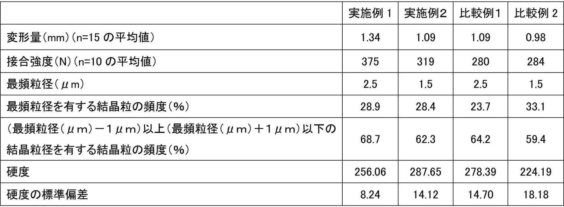
表1で示されるように、実施例1および2においては、比較例1および2と比較して、接合強度が顕著に向上するものとなった。また、最頻粒径が2.50μm以上である、および接合面における硬度の標準偏差が10.00以下である、実施例1は、接合強度がさらに向上する結果となった。
以上のように、本発明のガイドワイヤによれば、接合強度が高いものとなる。また、トルク伝達性の向上、応力集中緩和による疲労強度の向上も見込まれる。
本出願は、2020年3月30日に出願された日本特許出願番号2020-061404に基づいており、その開示内容は、参照され、全体として、組み入れられている。
10 ガイドワイヤ、
20 コアワイヤ、
21 第1ワイヤ、
22 第2ワイヤ、
30 コイル、
31、32、51 固定部材、
34 第1外径一定部、
35 第1テーパー部、
36 先端部、
37 接合部、
38 第2外径一定部、
39 第2テーパー部、
40 第3外径一定部、
41 先端側被覆層、
50 筒状部材、
52 テーパー部、
60 基端側被覆層、
61 内層、
62 外層、
63 線条体、
70 突出部。
20 コアワイヤ、
21 第1ワイヤ、
22 第2ワイヤ、
30 コイル、
31、32、51 固定部材、
34 第1外径一定部、
35 第1テーパー部、
36 先端部、
37 接合部、
38 第2外径一定部、
39 第2テーパー部、
40 第3外径一定部、
41 先端側被覆層、
50 筒状部材、
52 テーパー部、
60 基端側被覆層、
61 内層、
62 外層、
63 線条体、
70 突出部。
Claims (3)
- 第1ワイヤと第2ワイヤとを固相接合させたガイドワイヤであって、
第1ワイヤおよび第2ワイヤは、Ni-Ti系合金からなり、
第1ワイヤと第2ワイヤとの接合面の金属組織の結晶粒の個数基準粒径分布において、結晶粒径の区間を1μmとしたとき、最頻粒径の頻度は25%以上であり、代表径が(最頻粒径(μm)-1μm)以上(最頻粒径(μm)+1μm)以下の頻度は60%以上である、ガイドワイヤ。 - 前記最頻粒径が2.50μm以上である、請求項1に記載のガイドワイヤ。
- 前記接合面における硬度の標準偏差が10.00以下である、請求項1または2に記載のガイドワイヤ。
Priority Applications (4)
| Application Number | Priority Date | Filing Date | Title |
|---|---|---|---|
| EP21781029.0A EP4112219A4 (en) | 2020-03-30 | 2021-03-01 | LEAD WIRE |
| JP2022511673A JP7557528B2 (ja) | 2020-03-30 | 2021-03-01 | ガイドワイヤ |
| CN202180026078.9A CN115348879B (zh) | 2020-03-30 | 2021-03-01 | 导丝 |
| US17/835,477 US12485252B2 (en) | 2020-03-30 | 2022-06-08 | Guide wire |
Applications Claiming Priority (2)
| Application Number | Priority Date | Filing Date | Title |
|---|---|---|---|
| JP2020061404 | 2020-03-30 | ||
| JP2020-061404 | 2020-03-30 |
Related Child Applications (1)
| Application Number | Title | Priority Date | Filing Date |
|---|---|---|---|
| US17/835,477 Continuation US12485252B2 (en) | 2020-03-30 | 2022-06-08 | Guide wire |
Publications (1)
| Publication Number | Publication Date |
|---|---|
| WO2021199831A1 true WO2021199831A1 (ja) | 2021-10-07 |
Family
ID=77927070
Family Applications (1)
| Application Number | Title | Priority Date | Filing Date |
|---|---|---|---|
| PCT/JP2021/007653 Ceased WO2021199831A1 (ja) | 2020-03-30 | 2021-03-01 | ガイドワイヤ |
Country Status (5)
| Country | Link |
|---|---|
| US (1) | US12485252B2 (ja) |
| EP (1) | EP4112219A4 (ja) |
| JP (1) | JP7557528B2 (ja) |
| CN (1) | CN115348879B (ja) |
| WO (1) | WO2021199831A1 (ja) |
Cited By (1)
| Publication number | Priority date | Publication date | Assignee | Title |
|---|---|---|---|---|
| WO2025099886A1 (ja) * | 2023-11-09 | 2025-05-15 | 朝日インテック株式会社 | 医療デバイス |
Citations (6)
| Publication number | Priority date | Publication date | Assignee | Title |
|---|---|---|---|---|
| JP4734029B2 (ja) * | 2005-05-23 | 2011-07-27 | テルモ株式会社 | ガイドワイヤの製造方法 |
| WO2013100045A1 (ja) | 2011-12-28 | 2013-07-04 | テルモ株式会社 | ガイドワイヤ |
| JP5985849B2 (ja) * | 2012-03-23 | 2016-09-06 | 株式会社豊田中央研究所 | 接合体、その製造方法および被接合部材 |
| US20160279391A1 (en) * | 2015-03-13 | 2016-09-29 | Lake Region Manufacturing, Inc. | Solid state methods for joining dissimilar metal guidewire segments without the use of tertiary material |
| JP2017113267A (ja) * | 2015-12-24 | 2017-06-29 | 住友電気工業株式会社 | 医療用ガイドワイヤ |
| JP2020061404A (ja) | 2018-10-05 | 2020-04-16 | 株式会社Screenホールディングス | 基板処理方法および基板処理装置 |
Family Cites Families (9)
| Publication number | Priority date | Publication date | Assignee | Title |
|---|---|---|---|---|
| JP4203358B2 (ja) * | 2002-08-08 | 2008-12-24 | テルモ株式会社 | ガイドワイヤ |
| CN100558423C (zh) * | 2003-12-18 | 2009-11-11 | 泰尔茂株式会社 | 导向线 |
| ATE466620T1 (de) | 2005-04-15 | 2010-05-15 | Terumo Corp | Führungsdraht |
| JP4734015B2 (ja) * | 2005-04-15 | 2011-07-27 | テルモ株式会社 | ガイドワイヤの製造方法 |
| JP5020630B2 (ja) * | 2006-12-28 | 2012-09-05 | テルモ株式会社 | ガイドワイヤ |
| EP2143460B1 (en) * | 2007-05-09 | 2015-07-22 | Japan Science and Technology Agency | Guide wire and stent |
| JP5472915B2 (ja) | 2010-05-24 | 2014-04-16 | 株式会社オーク製作所 | 放電ランプ |
| US9636485B2 (en) * | 2013-01-17 | 2017-05-02 | Abbott Cardiovascular Systems, Inc. | Methods for counteracting rebounding effects during solid state resistance welding of dissimilar materials |
| JP6109329B2 (ja) | 2014-03-14 | 2017-04-05 | 古河電気工業株式会社 | Cu−Al−Mn系合金材とその製造方法、及びそれを用いた棒材または板材 |
-
2021
- 2021-03-01 EP EP21781029.0A patent/EP4112219A4/en active Pending
- 2021-03-01 CN CN202180026078.9A patent/CN115348879B/zh active Active
- 2021-03-01 JP JP2022511673A patent/JP7557528B2/ja active Active
- 2021-03-01 WO PCT/JP2021/007653 patent/WO2021199831A1/ja not_active Ceased
-
2022
- 2022-06-08 US US17/835,477 patent/US12485252B2/en active Active
Patent Citations (6)
| Publication number | Priority date | Publication date | Assignee | Title |
|---|---|---|---|---|
| JP4734029B2 (ja) * | 2005-05-23 | 2011-07-27 | テルモ株式会社 | ガイドワイヤの製造方法 |
| WO2013100045A1 (ja) | 2011-12-28 | 2013-07-04 | テルモ株式会社 | ガイドワイヤ |
| JP5985849B2 (ja) * | 2012-03-23 | 2016-09-06 | 株式会社豊田中央研究所 | 接合体、その製造方法および被接合部材 |
| US20160279391A1 (en) * | 2015-03-13 | 2016-09-29 | Lake Region Manufacturing, Inc. | Solid state methods for joining dissimilar metal guidewire segments without the use of tertiary material |
| JP2017113267A (ja) * | 2015-12-24 | 2017-06-29 | 住友電気工業株式会社 | 医療用ガイドワイヤ |
| JP2020061404A (ja) | 2018-10-05 | 2020-04-16 | 株式会社Screenホールディングス | 基板処理方法および基板処理装置 |
Non-Patent Citations (1)
| Title |
|---|
| See also references of EP4112219A4 |
Cited By (1)
| Publication number | Priority date | Publication date | Assignee | Title |
|---|---|---|---|---|
| WO2025099886A1 (ja) * | 2023-11-09 | 2025-05-15 | 朝日インテック株式会社 | 医療デバイス |
Also Published As
| Publication number | Publication date |
|---|---|
| EP4112219A4 (en) | 2023-03-08 |
| CN115348879B (zh) | 2023-06-02 |
| JPWO2021199831A1 (ja) | 2021-10-07 |
| JP7557528B2 (ja) | 2024-09-27 |
| CN115348879A (zh) | 2022-11-15 |
| EP4112219A1 (en) | 2023-01-04 |
| US12485252B2 (en) | 2025-12-02 |
| US20220296861A1 (en) | 2022-09-22 |
Similar Documents
| Publication | Publication Date | Title |
|---|---|---|
| KR101326997B1 (ko) | 가이드 와이어 | |
| JP6842933B2 (ja) | ガイドワイヤおよびガイドワイヤの製造方法 | |
| CN1575824A (zh) | 导向线 | |
| WO2021199831A1 (ja) | ガイドワイヤ | |
| JP5473677B2 (ja) | ガイドワイヤ | |
| JP2017113267A (ja) | 医療用ガイドワイヤ | |
| JP4136370B2 (ja) | 医療用ガイドワイヤ用芯材の製造方法および医療用ガイドワイヤ | |
| CN101537222A (zh) | 导向线 | |
| WO2022102653A1 (ja) | ガイドワイヤ | |
| US20240024639A1 (en) | Guide wire and method for producing guide wire | |
| US20250262416A1 (en) | Guide wire and method for producing guide wire | |
| JP2022077836A (ja) | ガイドワイヤ | |
| CN115955987B (zh) | 导丝 | |
| JP4478720B2 (ja) | 医療用ガイドワイヤ用芯材の製造方法および医療用ガイドワイヤ | |
| JP2022077832A (ja) | ガイドワイヤ | |
| JP2005211511A (ja) | ガイドワイヤ | |
| JP2004181089A (ja) | ガイドワイヤ | |
| JP4288048B2 (ja) | ガイドワイヤ | |
| WO2022080021A1 (ja) | ガイドワイヤ及びガイドワイヤの製造方法 | |
| JP4855448B2 (ja) | ガイドワイヤの製造方法 | |
| JP2006204710A (ja) | 医療用ガイドワイヤ | |
| JP2006263083A (ja) | 医療用ガイドワイヤ |
Legal Events
| Date | Code | Title | Description |
|---|---|---|---|
| 121 | Ep: the epo has been informed by wipo that ep was designated in this application |
Ref document number: 21781029 Country of ref document: EP Kind code of ref document: A1 |
|
| ENP | Entry into the national phase |
Ref document number: 2022511673 Country of ref document: JP Kind code of ref document: A |
|
| ENP | Entry into the national phase |
Ref document number: 2021781029 Country of ref document: EP Effective date: 20220930 |
|
| NENP | Non-entry into the national phase |
Ref country code: DE |