WO2021200133A1 - 眼鏡レンズの評価装置 - Google Patents
眼鏡レンズの評価装置 Download PDFInfo
- Publication number
- WO2021200133A1 WO2021200133A1 PCT/JP2021/010715 JP2021010715W WO2021200133A1 WO 2021200133 A1 WO2021200133 A1 WO 2021200133A1 JP 2021010715 W JP2021010715 W JP 2021010715W WO 2021200133 A1 WO2021200133 A1 WO 2021200133A1
- Authority
- WO
- WIPO (PCT)
- Prior art keywords
- evaluation
- point
- lens
- apparent
- spectacle lens
- Prior art date
- Legal status (The legal status is an assumption and is not a legal conclusion. Google has not performed a legal analysis and makes no representation as to the accuracy of the status listed.)
- Ceased
Links
Images





Classifications
-
- G—PHYSICS
- G02—OPTICS
- G02C—SPECTACLES; SUNGLASSES OR GOGGLES INSOFAR AS THEY HAVE THE SAME FEATURES AS SPECTACLES; CONTACT LENSES
- G02C7/00—Optical parts
- G02C7/02—Lenses; Lens systems ; Methods of designing lenses
- G02C7/024—Methods of designing ophthalmic lenses
- G02C7/025—Methods of designing ophthalmic lenses considering parameters of the viewed object
-
- G—PHYSICS
- G01—MEASURING; TESTING
- G01M—TESTING STATIC OR DYNAMIC BALANCE OF MACHINES OR STRUCTURES; TESTING OF STRUCTURES OR APPARATUS, NOT OTHERWISE PROVIDED FOR
- G01M11/00—Testing of optical apparatus; Testing structures by optical methods not otherwise provided for
- G01M11/02—Testing optical properties
- G01M11/0242—Testing optical properties by measuring geometrical properties or aberrations
- G01M11/0257—Testing optical properties by measuring geometrical properties or aberrations by analyzing the image formed by the object to be tested
- G01M11/0264—Testing optical properties by measuring geometrical properties or aberrations by analyzing the image formed by the object to be tested by using targets or reference patterns
-
- G—PHYSICS
- G02—OPTICS
- G02C—SPECTACLES; SUNGLASSES OR GOGGLES INSOFAR AS THEY HAVE THE SAME FEATURES AS SPECTACLES; CONTACT LENSES
- G02C7/00—Optical parts
- G02C7/02—Lenses; Lens systems ; Methods of designing lenses
- G02C7/024—Methods of designing ophthalmic lenses
- G02C7/027—Methods of designing ophthalmic lenses considering wearer's parameters
-
- G—PHYSICS
- G02—OPTICS
- G02C—SPECTACLES; SUNGLASSES OR GOGGLES INSOFAR AS THEY HAVE THE SAME FEATURES AS SPECTACLES; CONTACT LENSES
- G02C7/00—Optical parts
- G02C7/02—Lenses; Lens systems ; Methods of designing lenses
- G02C7/06—Lenses; Lens systems ; Methods of designing lenses bifocal; multifocal ; progressive
- G02C7/061—Spectacle lenses with progressively varying focal power
Definitions
- the present invention relates to an evaluation device for a spectacle lens.
- the spectacle lens By rotating the eyeball for each evaluation point and determining the appearance when the evaluation point is fixed through the spectacle lens (in other words, the distortion of the image of the evaluation point captured at the fovea centralis, etc.), the spectacle lens is used.
- Techniques for evaluation are known (see, for example, Japanese Patent No. 4481093).
- the retina has significantly higher visual acuity in the fovea. Therefore, by evaluating the spectacle lens based on the distortion of the image captured in the fovea centralis, an appropriate evaluation result of the spectacle lens can be obtained.
- the distortion of the image captured in the peripheral part of the retina other than the fovea may be unpleasant.
- a person senses the distance of the object by using the difference in the positions of images generated on the retinas of the left and right eyes (that is, parallax) as a clue.
- the image on the peripheral part of the retina is distorted, not only the object looks distorted, but also the person may recognize that the object is at a distance different from the original object distance.
- the present invention has been made in view of the above circumstances, and an object of the present invention is that the spectacle lens can be evaluated in consideration of not only the image captured in the peripheral portion of the retina other than the fovea centralis but also the image captured in the peripheral portion of the retina other than the fovea centralis. , To provide an evaluation device for spectacle lenses.
- the spectacle lens evaluation device sets a specific position in the space to be evaluated as a fixed viewpoint, and wears a pair of left and right spectacle lenses to fix the fixed viewpoint on the lens.
- a pair of left and right spectacle lenses are worn for each of the fixation position setting unit that sets the line-of-sight passing position and a plurality of evaluation points set in the space, and the fixation point is fixed through the line-of-sight passing position.
- the apparent position calculation unit that calculates the apparent position
- the difference calculation unit that calculates the difference between the calculated apparent position and the reference position of the evaluation point for each of the plurality of evaluation points, and the difference calculation unit. It is provided with an evaluation index calculation unit that calculates an evaluation index that statistics the difference for each evaluation point calculated by.
- the evaluation index calculation unit may be configured to calculate the evaluation index using the following equation.
- DI Evaluation index n: Number of samples of evaluation points set in space
- ⁇ i Difference between the apparent position and the reference position for each evaluation point.
- the difference between the apparent position and the reference position for each evaluation point is defined by, for example, the following equation.
- ⁇ i D i -D i0
- D i the reciprocal of the distance from the position of an apparent each evaluation point to both the eye point
- D i0 the reciprocal of the distance from the reference position of each evaluation point to both the eye point.
- the difference between the apparent position and the reference position for each evaluation point is defined by, for example, the following equation.
- ⁇ i
- However, ⁇ i The angle formed by the vector from the apparent position of each evaluation point to the midpoint of both eyes and the vector from the reference position of each evaluation point to the midpoint of both eyes.
- the reference position is, for example, the position of the evaluation point set on the space itself.
- the reference position when the spectacle lens is a lens other than the single focus lens, the reference position may be the apparent position when the single focus lens having the same power as the spectacle lens is worn.
- the spectacle lens in the spectacle lens evaluation device, can be evaluated in consideration of not only the image captured in the peripheral portion of the retina other than the fovea centralis but also the image captured in the peripheral portion of the retina other than the fovea centralis.
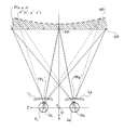
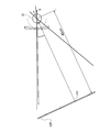
- FIG. 1 It is a block diagram which shows the schematic structure of the evaluation apparatus of the spectacle lens which concerns on one Embodiment of this invention. It is a flowchart of the evaluation process of a spectacle lens executed in one Embodiment of this invention. It is a figure which shows an example of the virtual optical model set in the virtual space in one Embodiment of this invention. It is a figure which shows an example of the virtual optical model set in the virtual space in one Embodiment of this invention. It is a figure which shows an example of the virtual optical model set in the virtual space in one Embodiment of this invention. It is a figure for demonstrating an example of the method of calculating an apparent point which is an apparent position of the evaluation point in a virtual space in one Embodiment of this invention.
- FIG. 1 is a block diagram showing a schematic configuration of an evaluation system 1 according to an embodiment of the present invention.
- the evaluation system 1 is a system for evaluating spectacle lenses, and includes an information processing terminal 10, an input device 20, and a display device 30 as shown in FIG.
- the information processing terminal 10 is an example of an evaluation device.
- the information processing terminal 10 is, for example, a desktop PC (Personal Computer).
- the input device 20 is, for example, a mouse and a keyboard
- the display device 30 is, for example, a display.
- the input device 20 and the display device 30 are connected to the information processing terminal 10 by wire or wirelessly.
- the information processing terminal 10, the input device 20, and the display device 30 are separate devices, but in another embodiment, these devices may be included in a single device.
- these devices include a notebook PC, a tablet terminal, a smartphone, and the like having the functions of the information processing terminal 10, the input device 20, and the display device 30.
- the evaluation system 1 is composed of a single notebook PC, a single tablet terminal, a single smartphone, and the like. According to this configuration, the evaluation system 1 can be carried around.
- the information processing terminal 10 includes a control unit 100 and a memory 110.
- the control unit 100 is, for example, a system LSI (Large-scale Integrated Circuit) equipped with a DSP (Digital Signal Processor) and a CPU (Central Processing Unit).
- the memory 110 includes an HDD (Hard Disk Drive), a RAM (Random Access Memory), and a ROM (Read Only Memory).
- the control unit 100 performs various controls by calling a program stored in the HDD or ROM and executing the called program in the DSP or CPU.
- the HDD, ROM, and RAM also store control parameters required for program execution.
- FIG. 2 shows a flowchart of the spectacle lens evaluation process (evaluation method) executed by using the evaluation program.
- the control unit 100 sets a virtual optical model for evaluating the spectacle lens to be evaluated in the virtual space (step S101).
- the spectacle lens to be evaluated may be, for example, a spectacle lens having basic specifications set by a spectacle lens manufacturer, or a spectacle lens scheduled to be sold to a patient.
- the control unit 100 sets each element (for example, a plane OP described later) in the virtual space, and the evaluation result (specifically) of the spectacle lens is based on each set element.
- the content of calculating the evaluation index DI) will be described in the above section, but the method of calculating the evaluation result using the virtual space is not indispensable.
- the control unit 100 may simply hold each element as numerical data, perform ray tracing using these numerical data, or perform an operation using a mathematical formula (details will be described later) to obtain an evaluation result.
- the spectacle lens model L is set based on the patient's prescription data received from the terminal of the spectacle store, for example, via the network.
- This prescription data includes, as an example, the results of optometry at an eyeglass store (for example, spherical refractive power, spectacle refractive power, spectacle axis direction, prism refractive power, prism base direction, addition power, distance PD (Pupillary Distance), etc.
- Prescription value data for near-field PD, etc. For example, eye point position, forward tilt angle, tilt angle, distance between apex, distance between pupils, etc.), frame data (for example, measurement result of frame tracer and template (for example) Data indicating the type of frame shape), type of spectacle lens (for example, single focus spherical lens, single focus aspherical lens, fatigue reduction lens, near vision lens, progressive power lens) ) Is included.
- a design type for example, a type having a wide clear vision range for near vision, a type having a wide clear vision range for far vision, etc.
- a method for setting the spectacle lens model L based on such prescription data is known, a specific description thereof will be omitted.
- FIG. 3 is a diagram showing an example of a virtual optical model set in the virtual space in step S101.
- the virtual optical model includes a spectacle lens model (more specifically, a pair of left and right spectacle lens models LL , LR ) and an eyeball model E (more specifically) showing the spectacle lens to be evaluated. pair of left and right eye model E L, E R) is included.
- the element corresponding to the left eye is subscripted with "L”
- the element corresponding to the right eye is subscripted with "R”.
- these elements are described without subscripts.
- the spectacle lens model for the left eye becomes the “spectacle lens model LL”
- the spectacle lens model for the right eye becomes the “spectacle lens model LR”
- these spectacle lens models LL and The generic name of LR is "glasses lens model L".
- the coordinate system of the virtual space is the XYZ Cartesian coordinate system.
- X, Y, 3 Z axes is the center O L of the spectacle lens model L L, the midpoint between the center O R of the spectacle lens model L R (hereinafter referred to as "both the eye point O".) In mutually perpendicular .
- the Z axis is an axis parallel to the paper surface of FIG. On the Z-axis, the center O R, both the eye point O and the center O L are arranged side by side.
- the X-axis is an axis parallel to the paper surface of FIG. 3 and is orthogonal to the Z-axis.
- the Y-axis is an axis extending in the vertical direction with respect to the paper surface of FIG. 3, and is orthogonal to the X-axis and the Z-axis.
- the eye model may be a well-known model such as the model eye of the lens strand, and is not limited to a complex model having all the tissues constituting the eye, for example, the main eye elements (for example, the main eye elements (). It may be a simple model with only the cornea and lens) and the retina.
- the position and angle of the spectacle lens model L with respect to the eyeball model E are determined based on, for example, layout data. If there is no layout data, the specified position and angle will be applied.
- the shape of the spectacle lens model L is set to the lens shape (cut lens shape) after the frame is inserted, for example, based on the frame data. If there is no layout data, the specified lens shape is set.
- the shape of the spectacle lens model L may be an uncut lens shape instead of a cut lens shape.
- the control unit 100 sets the fixed viewpoint FP in the virtual space (step S102). Control unit 100, by ray tracing, and wearing a spectacle lens View fixation point FP (for fixation) line-of-sight passing position FP on the spectacle lens when '(line of sight passing positions on spectacle lenses Model L L FP L' and set in the virtual space by calculating the spectacle lens model L sight passing position on R FP R ').
- Control unit 100 the eye model E L, the E R swirling, in the virtual space, setting a fixation state of fixation of the fixation point FP through sight passing position FP L 'and the spectacle lens model L R (step S103 ).
- the control unit 100 sets a specific position on the space to be evaluated as the fixed-viewpoint FP, and wears a pair of left and right spectacle lenses to fix the fixed-viewpoint FP. It operates as a fixation position setting unit that sets the line-of-sight passing position FP'on the lens.
- the control unit 100 sets (arranges) a plurality of evaluation points P (point sequence) in the space to be evaluated (step S104).
- This score sequence changes depending on how the evaluation target is set. For example, when evaluating the three-dimensional distortion of the entire space, a sequence of points is set so that the evaluation points P are evenly distributed in the space to be evaluated (that is, the evaluation points P are XYZ over the entire space). They are evenly spaced or evenly spaced in each direction). Further, assuming a situation where the wearer looks at a newspaper, for example, a sequence of points may be set so that the evaluation points P are evenly distributed on a plane of a finite distance in front of the eyes.
- the control unit 100 is an apparent position of each of the plurality of evaluation points P set in step S104, and is an apparent position of the evaluation point P in the fixation state set in steps S102 and S103.
- a position (hereinafter, this position is referred to as "apparent point P'") is calculated (step S105). That is, in step S105, the control unit 100 is the apparent position P'of each of the plurality of evaluation points P set in the space, and is fixed through the pair of left and right spectacle lenses and the line-of-sight passing position FP'. It operates as an apparent position calculation unit that calculates the apparent position P'when the viewpoint FP is fixed.
- the apparent point P' may be referred to as an apparent position P'or an apparent point P'in some cases.
- the control unit 100 calculates the difference between the position of each apparent point P'calculated in step S104 and the reference position of each evaluation point P (step S106), and calculates the difference between the calculated positions for each evaluation point.
- the statistical evaluation index DI is calculated (step S107). That is, in step S106, the control unit 100 calculates the difference between the apparent position P'calculated by the position calculation unit and the reference position of the evaluation point P for each of the plurality of evaluation points P. Works as. Further, in step S107, the control unit 100 calculates an evaluation index that stats the difference between the apparent position P'and the reference position of the evaluation point P for each evaluation point calculated by the difference calculation unit. Operates as a calculation unit.
- the evaluation index DI is an index for evaluating changes in the visual field (for example, distortion, correction effect, etc.) when looking at an object while wearing the spectacle lens to be evaluated.
- the reference position of each evaluation point P is a position preset as the position where the evaluation point P should originally be.
- the reference position of each evaluation point P is the position of each evaluation point P itself or the apparent position of each evaluation point P based on a certain situation.
- the evaluation range is a plane perpendicular to the straight line from the midpoint O of both eyes to the fixed viewpoint FP and including the fixed viewpoint FP.
- a position perpendicular to the straight line from the midpoint O of both eyes to the apparent point of the fixed viewpoint FP and on the plane including the apparent point of the fixed viewpoint FP is set as the reference position of each evaluation point P. ..
- the position itself of the evaluation point P set in the plane of the evaluation range (the apparent position of the evaluation point P when the fixed viewpoint FP is fixed with the naked eye) is the reference position of the evaluation point P. May be set as.
- a single focus lens having the same power as the spectacle lens to be evaluated for example, a single focus lens having the same power as the distance power of the both near and far progressive power lens to be evaluated.
- the apparent position of the evaluation point P may be set as the reference position of the evaluation point P.
- the evaluation points P to be statistically may be all the evaluation points P set in the virtual space, or some evaluation points P set in the virtual space. You may. Some evaluation points P are, for example, evaluation points P that can be seen through a specific range on the spectacle lens (upper half, lower half, a portion within a radius of 20 mm from the center, etc.), or a specific distance range in the virtual space. It may be the evaluation point P set in.
- the fixed viewpoint FP is set at a position about 40 cm away from, for example, the spectacle lens model L (more specifically, the midpoint O of both eyes).
- the line-of-sight passing position FP'on the spectacle lens is the near region of the spectacle lens (for example, when the progressive band length is 11 mm, the position is 11 mm below the geometric center of the lens). That is, the left and right eyes rotate downward to fix the fixed viewpoint FP.
- the evaluation point P is set on a flat surface assuming, for example, the surface of a newspaper or book read by the wearer, or the screen of a notebook PC or tablet terminal.
- a reference numeral OP is attached to such a plane included in the evaluation range (for example, a plane perpendicular to the line of sight for fixing the fixed viewpoint FP).
- the evaluation points P are evenly set in the plane OP (equally spaced or unevenly spaced in each direction of XY).
- an apparent point P' which is an apparent position of the evaluation point P is obtained.
- the surface including each apparent point P' (hereinafter referred to as "apparent surface AP") indicates the apparent shape of the plane OP.
- the difference between the apparent point P'of each evaluation point P and the reference position is calculated.
- the difference between the plane OP and the apparent surface AP shown is conceptually indicated by the area of the hatching region in FIG.
- step S106 of FIG. 2 conceptually, the larger the area of this hatched region, the larger the change in the visual field (for example, distortion, correction effect, etc.) when wearing the spectacle lens with respect to the reference state (here, when the naked eye is used). Evaluation results are obtained.
- FIG. 4 shows an example of a virtual optical model similar to that in FIG.
- FIG. 4 is a diagram in which a plane OP'is added to FIG. 3 and a region between the plane OP'and the apparent surface AP is shown by hatching. Since there is a slight base-in or base-out prism effect at the line-of-sight passing position FP'on the spectacle lens to be evaluated, the apparent position of the fixed viewpoint FP is behind or in front of the position of the fixed viewpoint FP in space. ..
- the plane OP'perpendicular to the straight line from the midpoint O of both eyes to the apparent position of the fixed viewpoint FP, including the apparent position of the fixed viewpoint FP is considered as the apparent surface that should be.
- the change in the visual field (evaluation result) when the spectacle lens is worn with respect to the reference state can be conceptually considered as the area of the hatched region of FIG.
- FIG. 5 shows an example of a virtual optical model similar to that in FIG.
- FIG. 5 is a diagram in which a curved surface OP "is added to FIG. 3 and a region between the curved surface OP" and the apparent surface AP is shown by hatching.
- the "curved surface OP" is the apparent appearance of the flat surface OP when the fixed-viewpoint FP is fixed through the same position by wearing spectacles with a single focus lens of the same prescription or fitting position instead of the spectacle lens to be evaluated.
- the spectacle lens to be evaluated is a lens other than a single focus lens, for example, a progressive refractive force lens
- the reference position of each evaluation point P is set on the curved surface OP ”.
- the change in the visual field (evaluation result) when the spectacle lens is worn with respect to the reference state can be conceptually considered as the area of the hatched region of FIG.
- the control unit 100 can set the evaluation area on the spectacle lens (in other words, the space to be evaluated, and the position and size of the visual field range).
- the field of view set here is, for example, a circle having a radius of n1 (for example, n1 is 300 mm) centered on the fixed viewpoint FP in the above-mentioned case (a case where the near portion of the bifocal progressive power lens is evaluated). It may be a surface or a rectangular surface centered on the fixed viewpoint FP (length n2 x width n3: for example, n2 is 400 mm and n3 is 800 mm).
- the space of the entire visual field is set as the space to be evaluated, and each evaluation point P is set in this set space.
- step S105 the control unit 100 calculates an apparent point P'which is an apparent position of the evaluation point P in the virtual space.
- 6 and 7 show a diagram for explaining an example of the calculation method.
- Figure 6 is an enlarged view showing the eye model E L and E R shown in FIG.
- the crystalline lens omitted in FIG. 3 is also shown.
- FIG. 7 is a diagram conceptually showing an example of a method of calculating the apparent point P'.
- the control unit 100 can calculate the direction vector of each light ray incident on the cornea and the passing point on the cornea. More specifically, the control unit 100, the retina goal M (left and right retinas goal M L, M R) to inverse tracing rays passing through the pupil center from, when light rays tracing back passes cornea position on the cornea (right and left cornea passing point K L, K R) with computing the (direction vector D L of the pair of left and right corneas incident light, D R) incident direction at which this ray is incident on the cornea calculate.
- the retina goal M left and right retinas goal M L, M R
- the corneal incident rays are not refracted by the spectacle lens, so the two intersect.
- the spectacle lens is worn, the corneal incident light is refracted by the spectacle lens, so that the two do not necessarily intersect.
- the plane LP and the plane RP are in an angled state as shown in FIG.
- Plane LP is a plane containing the straight line and the straight line D L connecting the corneal pass point K L and K R.
- Plane RP is a plane containing the straight line and the straight line D R connecting the corneal pass point K L and K R.
- Control unit 100 as a way of obtaining an apparent point P ', the plane LP and the angle between the plane RP to the plane CP that bisects straight line D L, projecting a D R, these straight lines obtained by projecting
- the points on the intersecting plane CP are obtained as apparent points P'(x', y', z').
- the N K unit vector to the cornea passes through point K L from the cornea passes through the point K R.
- Control unit 100 obtains a straight line LN R extending 'straight line LN L and unit vector D extends in L' R unit vector D, by solving the triangular P'K L K R on a plane CP sine theorem, the apparent point Obtain P'(x', y', z').
- the control unit 100 obtains an apparent point P'which is an apparent point for all the evaluation points P.
- the apparent surface AP is represented by a plurality of apparent points P'(all apparent points P'obtained here) in the same manner that the plane OP is represented by a plurality of evaluation points P. ..
- step S105 the control unit 100 calculates a set of a plurality of apparent points P'.
- step S106 the control unit 100 calculates the difference between the position of the apparent point P'and the corresponding reference position of the evaluation point P.
- the difference between the apparent point P'and the reference position P 0 can be calculated by dividing it into the difference ⁇ A in the visual direction and the difference ⁇ D in the depth (the reciprocal of the distance from the midpoint O of both eyes).
- the difference in the viewing direction, the straight line P 0 from the apparent point P 'for each evaluation point P and the direction vector of the straight line P'O to both the eye point O, the reference position P 0 for each evaluation point P to both the eye point O It is defined as the absolute value of the sign of the angle ⁇ formed by the direction vector of O.
- the depth is the reciprocal of the distance from the midpoint O of both eyes.
- the depth difference ⁇ D is expressed by the following equation.
- step S107 the control unit 100 calculates the evaluation index DI by statistically calculating the difference between the reference position P 0 of the evaluation point P set in the space to be evaluated and its apparent position P'.
- the evaluation index DI is calculated by the following equation (1).
- Equation (1) n: Number of samples of evaluation point P set in space ⁇ i : Difference between apparent position P'for each evaluation point P and reference position P 0
- the evaluation index DI may be represented by one or both of the evaluation index DIA and the evaluation index DID shown in the following equation.
- Evaluation index DIA is a representation of the difference delta i the viewing direction of the difference .DELTA.A i
- the evaluation index DID is a representation of the difference delta i in the difference [Delta] D i depth.
- DIA Evaluation index based on the difference in viewing direction
- DID Evaluation index based on the difference in depth ⁇ A i :
- D i for each evaluation point P, the difference between the reciprocal D i of the distance from the position P 'of the apparent to both the eye point O, the inverse D i0 of the distance from the reference position P 0 to both the eye point O (i.e. , D i -D i0) Is.
- the coordinate system of the virtual space is not limited to the XYZ Cartesian coordinate system, and may be replaced with a coordinate system defined by the azimuth angle and the depth.
- the position of each evaluation point P is represented by, for example, P (D, T, C).
- D is the depth of the evaluation point P (depth is the reciprocal of the distance from the midpoint O of both eyes)
- T is the tangent of the vertical azimuth
- C is the tangent of the horizontal azimuth.
- the depth D, the vertical azimuth T, and the horizontal azimuth C are expressed by the following equations, respectively.
- the evaluation point P can be indicated by any of P (x, y, z), P (D, T, C), and P (D, ⁇ , ⁇ ). That is, the sequence of evaluation points P can be sampled in the xyz coordinate system at, for example, equidistant or unequal intervals on each axis, and in the DTC coordinate system, equidistant or unequal intervals on each axis. It is also possible to sample at equal intervals or uneven intervals for each axis in the D- ⁇ - ⁇ coordinate system.
- n is the number of samples of the evaluation points P arranged in the space in front of the spectacle lens
- ⁇ Di is the position difference ⁇ D (x, y, z) for each evaluation point P arranged in this space.
- the evaluation index DI is an evaluation result for evaluating the appearance of the front space through the spectacle lens.
- n x Number of evaluation points P samples arranged in the X-axis direction in the front space
- n y Number of evaluation points P samples arranged in the Y-axis direction in the front space
- n z Evaluation points arranged in the Z-axis direction in the front space
- Number of samples of P ⁇ A ijk Difference in viewing direction for each evaluation point P set in the front space ⁇ A (x, y, z)
- ⁇ D ijk Difference in depth for each evaluation point P set in the front space ⁇ D (x, y, z) (Evaluation points P are arranged at equal or uneven intervals in each direction)
- the anterior space which is the evaluation range
- the above equation (1) can be replaced with a more specific following equation.
- n D Number of samples of evaluation points P lined up in the depth direction in the front space
- n T Number of samples of evaluation points P lined up in the direction of the vertical orientation angle in the front space
- n C Number of samples of evaluation points P lined up in the front space
- ⁇ A ijk Difference in viewing direction for each evaluation point P set in the front space ⁇ A (D, T, C)
- ⁇ D ijk Difference in depth for each evaluation point P set in the front space ⁇ D (D, T, C) (Evaluation points P are arranged at equal or uneven intervals in each direction)
- the anterior space which is the evaluation range
- the above equation (1) can be replaced with a more specific following equation.
- n ⁇ Number of samples of evaluation points P lined up in the direction of the radial azimuth in the front space
- n ⁇ Number of samples of evaluation points P lined up in the direction of the quadrant azimuth in the front space
- ⁇ A ijk Set in the front space Difference in viewing direction for each evaluation point P ⁇ A (D, ⁇ , ⁇ )
- ⁇ D ijk Difference in depth for each evaluation point P set in the front space ⁇ D (D, ⁇ , ⁇ ) (Evaluation points P are arranged at equal or uneven intervals in each direction)
- the evaluation index may be calculated by statistically calculating all the evaluation points P arranged in the front space, but the evaluation index may be calculated for some evaluation points P arranged in the front space. ..
- the evaluation index DI (or evaluation index DIA, DID) is an index that quantifies and indicates the change in the visual field when the spectacle lens is worn with respect to the reference state. The larger the value of the evaluation index DI, the larger the change in the visual field with respect to the reference state.
- the evaluation index DI (or evaluation index DIA, DID) determines the deviation of the surrounding evaluation point P from the reference position P 0 in a state where the set fixed viewpoint FP is fixed through the line-of-sight passing position FP'on the spectacle lens. It is an index included as an evaluation target. That is, the evaluation index DI is an evaluation content that considers not only the image captured in the peripheral part of the retina other than the fovea but also the image captured in the peripheral part of the retina other than the fovea.
- the evaluation index DI (or the evaluation index).
- the evaluation range is the space in front of the spectacle lens, and in the second embodiment, the evaluation range is a plane separated from the midpoint O of both eyes by a specific distance.
- the evaluation target is a bifocal progressive power lens, and the reference state is the naked eye state.
- the bifocal progressive power lens to be evaluated is common to Example 1 and Example 2.
- the specifications of this bifocal progressive power lens are as follows.
- CVD Corneal Vertex Distance
- corneal vertices which is the distance between the posterior apex of the spectacle lens and the anterior surface of the cornea (corneal apex).
- the evaluation range is a conical space having a radius angle of 50.2 degrees (referred to as “conical space CS” for convenience) with the midpoint O of both eyes as the apex.
- the depth range of the conical space CS is in the range of 0D to 3.5D (in other words, from infinity to 286 mm).
- the position on the spectacle lens through which the line of sight to the fixed viewpoint FP set at an infinity distance passes is a position 4 mm above the geometric center of the spectacle lens.
- the evaluation area on the spectacle lens (in other words, the range on the spectacle lens through which the line of sight to each evaluation point P arranged in the entire conical space CS passes) is geometric.
- the range is about ⁇ 40 mm centered on the center.
- the evaluation area on the spectacle lens is referred to as "lens evaluation area EA".
- FIG. 8 shows the parallax of the left and right eyes (in other words, the plane OP at an infinite distance from the midpoint O of both eyes) when the spectacle lens (bifocal progressive power lens) of Example 1 is worn and the depth is 0D. It is a figure which shows the parallax of the left-right eye at the time.
- FIG. 9 shows the parallax of the left and right eyes when the depth is 3.5D when the spectacle lens of the first embodiment is worn (in other words, the parallax of the left and right eyes when the plane OP 286 mm away from the midpoint O of both eyes is viewed). It is a figure which shows. In each of the figures of FIGS.
- the circles indicate the positions of the evaluation points P when the evaluation point P is viewed with the right eye
- the triangular marks indicate the evaluation points when the evaluation point P is viewed with the left eye. Indicates the position of P. The farther the two positions are, the larger the parallax is.
- the vertical axis indicates the vertical position in the conical space CS
- the horizontal axis indicates the horizontal position in the conical space CS.
- the total number of evaluation points P set in the conical space CS is 1548.
- the circle mark indicating the position of the right eye retina and the triangle mark indicating the position of the left eye retina of each evaluation point P are substantially overlapped (at the same position) in the upper half of the lens, and the parallax is close to zero. .. There is some parallax in the lower half of the lens.
- the magnitude of the parallax is relatively different for each evaluation point P, and the parallax is slightly larger in the lower half of the lens than in the upper half of the lens.
- arrow marks are added to the three evaluation points P in FIG. 9 for the convenience of showing that the parallax when wearing the spectacle lens is particularly large in the peripheral portion in the visual field.
- This arrow mark is a mark indicating an arrow from the position when viewed with the left eye to the position when viewed with the right eye.
- the apparent position P'of each evaluation point P is calculated by the above-mentioned method, and the difference ⁇ D in depth and the difference ⁇ A in the viewing direction are set in the specified range (with the evaluation target). It can be statistic in the space).
- the evaluation score is 1548
- the evaluation index DID based on the depth difference is 0.0857
- the evaluation index DIA based on the visual direction difference is 0.0326.
- the space in which the evaluation points P (total number: 600) at the tip of each line of sight passing through the upper half area of the lens evaluation area EA (referred to as “lens evaluation area EA U” for convenience) are arranged. Is the evaluation range, the evaluation index DID is 0.0586, and the evaluation index DIA is 0.0097.
- evaluation points P (Total: 948) in the previous sight line passing lower half area (for convenience referred to as "lens evaluation area EA D".)
- the evaluation index DID is 0.0991
- the evaluation index DIA is 0.0409.
- the evaluation index DID is 0.0393 and the evaluation index DIA is , 0.0322.
- the evaluation index DID is 0.0052.
- the evaluation index DIA is 0.0097.
- evaluation points P (Total: 117) of the depth 0D If is the evaluation range insofar as arranged, the evaluation index DID is 0.0501, The evaluation index DIA is 0.0405.
- the evaluation index DID is 0.1385 and the evaluation index DIA is , 0.0335.
- the evaluation index DID is 0.0970 when the evaluation range is the range in which the evaluation points P (total number: 75) having a depth of 3.5D are arranged at the tip of each line of sight passing through the lens evaluation area EA U. Yes, the evaluation index DIA is 0.0099.
- the evaluation index DID is 0.1588 when the evaluation range is the range in which the evaluation points P (total number: 121) having a depth of 3.5D are arranged at the tip of each line of sight passing through the lens evaluation area EA D. Yes, the evaluation index DIA is 0.0419.
- the lens evaluation area EA D (in other words, the near part rather than the distance part) is passed through the lens evaluation area EA U. It can be seen that the difference between the visual direction of the apparent position and the reference position tends to be larger when viewed.
- Example 2 the situation (FIG. 10) in which the newspaper is spread through the near portion of the bifocal progressive power lens is evaluated.
- the fixation point FP is at a distance of 40 cm from the midpoint O of both eyes.
- the fixed viewpoint FP is slightly diagonally below the eye because it is viewed through the near portion (specifically, a position 11 mm below the geometric center of the lens).
- a plane OP perpendicular to the straight line from the midpoint O of both eyes to the fixed viewpoint FP is set as the paper surface (plane) of the newspaper, and the evaluation point P is set on this plane.
- the evaluation range is a rectangular plane having a horizontal direction of 80 cm and a vertical direction of 40 cm.
- FIG. 11 is a view similar to that of FIGS. 8 and 9, and is the left and right eyes when the plane OP arranged diagonally downward is viewed when the spectacle lens (progressive power lens for bifocals) of the second embodiment is worn. It is a figure which shows the parallax of.
- Example 2 when the entire plane OP is set as the evaluation range, the evaluation index DID is 0.1165 and the evaluation index DIA is 0.0350.
- the same arrow mark as in FIG. 9 is added to FIG.
- a situation in which the wearer looks at a short distance diagonally downward for example, a situation in which the wearer reads a newspaper or a book, or a screen of a notebook PC or a tablet terminal.
- the parallax of the left and right eyes with respect to the naked eye state is large in the peripheral portion in the visual field away from the fixed viewpoint FP.
- the side that provides the spectacle lens is in the field of view, for example, for a patient who tends to feel uncomfortable with distortion of the image of the peripheral part in the field of view, for example, in a situation of looking at a short distance diagonally downward. It is possible to propose a spectacle lens with less image distortion in the peripheral portion of the lens.
- the embodiment of the present application also includes a content obtained by appropriately combining an embodiment or the like or a self-explanatory embodiment or the like which is exemplified in the specification.
Landscapes
- Physics & Mathematics (AREA)
- Health & Medical Sciences (AREA)
- Ophthalmology & Optometry (AREA)
- General Physics & Mathematics (AREA)
- General Health & Medical Sciences (AREA)
- Optics & Photonics (AREA)
- Geometry (AREA)
- Chemical & Material Sciences (AREA)
- Analytical Chemistry (AREA)
- Eyeglasses (AREA)
Abstract
眼鏡レンズの評価装置を、評価対象となる空間上の特定位置を固視点と設定し、左右一対の眼鏡レンズを装用して固視点を固視する際のレンズ上の視線通過位置を設定する固視位置設定部と、空間上に設定された複数の評価点の各々に対し、左右一対の眼鏡レンズ装用し且つ視線通過位置を通して固視点を固視する状態での、見かけ上の位置を算出する見かけ位置算出部と、複数の評価点の各々について、算出された見かけ上の位置と、評価点の基準位置との差分を算出する差分算出部と、差分算出部により算出された評価点毎の差分を統計した評価指数を算出する評価指数算出部と、を備える構成とする。
Description
本発明は、眼鏡レンズの評価装置に関する。
各評価点に対して眼球を回旋させて、眼鏡レンズを通じて評価点を固視したときの見え方(言い換えると、中心窩でとらえた評価点の像の歪み等)を求めることにより、眼鏡レンズを評価する技術が知られている(例えば特許第4481093号公報参照)。網膜は、中心窩での視力が際立って高い。そのため、中心窩でとらえた像の歪み等に基づいて眼鏡レンズを評価することにより、眼鏡レンズの適切な評価結果が得られる。
しかし、眼鏡レンズを装用する装用者によっては、中心窩以外の網膜周辺部でとらえた像の歪み等(言い換えると、視野内の周辺部の像の歪み等)を不快に感じることがある。両眼で対象物を見る場合、人は、左右眼の網膜上に生成される像の位置の差(すなわち視差)を手掛かりに、対象物の距離を感知する。網膜周辺部上の像に歪みがあると、人は、物が歪んで見えるだけではなく、本来の物体距離と異なる距離に物があるとご認識することがある。
本発明は上記の事情に鑑みてなされたものであり、その目的とするところは、中心窩だけでなく中心窩以外の網膜周辺部でとらえた像も考慮して眼鏡レンズを評価することができる、眼鏡レンズの評価装置を提供することである。
本発明の一実施形態に係る眼鏡レンズの評価装置は、評価対象となる空間上の特定位置を固視点と設定し、左右一対の眼鏡レンズを装用して固視点を固視する際のレンズ上の視線通過位置を設定する固視位置設定部と、空間上に設定された複数の評価点の各々に対し、左右一対の眼鏡レンズ装用し且つ視線通過位置を通して固視点を固視する状態での、見かけ上の位置を算出する見かけ位置算出部と、複数の評価点の各々について、算出された見かけ上の位置と、評価点の基準位置との差分を算出する差分算出部と、差分算出部により算出された評価点毎の差分を統計した評価指数を算出する評価指数算出部と、を備える。
本発明の一実施形態において、評価指数算出部は、次式を用いて評価指数を算出する構成としてもよい。
 但し、
但し、
DI :評価指数
n :空間上に設定される評価点のサンプル数
Δi :評価点毎の見かけ上の位置と基準位置との差分
である。
DI :評価指数
n :空間上に設定される評価点のサンプル数
Δi :評価点毎の見かけ上の位置と基準位置との差分
である。
本発明の一実施形態において、評価点毎の見かけ上の位置と基準位置との差分は、例えば次式により定義される。
Δi=Di-Di0
但し、
Di:評価点毎の見かけ上の位置から両眼中点までの距離の逆数
Di0:評価点毎の基準位置から両眼中点までの距離の逆数
である。
Δi=Di-Di0
但し、
Di:評価点毎の見かけ上の位置から両眼中点までの距離の逆数
Di0:評価点毎の基準位置から両眼中点までの距離の逆数
である。
本発明の一実施形態において、評価点毎の見かけ上の位置と基準位置との差分は、例えば次式により定義される。
Δi=|sinαi|
但し、
αi:評価点毎の見かけ上の位置から両眼中点へのベクトルと、評価点毎の基準位置から両眼中点へのベクトルと、がなす角度
である。
Δi=|sinαi|
但し、
αi:評価点毎の見かけ上の位置から両眼中点へのベクトルと、評価点毎の基準位置から両眼中点へのベクトルと、がなす角度
である。
本発明の一実施形態において、基準位置は、例えば空間上に設定された評価点の位置そのものである。
本発明の一実施形態において、眼鏡レンズが単焦点レンズ以外のレンズである場合、基準位置は、眼鏡レンズと同じ度数を持つ単焦点レンズを装用したときの見かけ上の位置であってもよい。
本発明の一実施形態によれば、眼鏡レンズの評価装置において、中心窩だけでなく中心窩以外の網膜周辺部でとらえた像も考慮して眼鏡レンズを評価することができる。
以下、本発明の一実施形態に係る眼鏡レンズの評価装置及びこの装置が実行する眼鏡レンズの評価方法について図面を参照しながら説明する。
図1は、本発明の一実施形態に係る評価システム1の概略構成を示すブロック図である。評価システム1は、眼鏡レンズを評価するシステムであり、図1に示されるように、情報処理端末10、入力装置20及び表示装置30を備える。
情報処理端末10は、評価装置の一例である。本実施形態において、情報処理端末10は、例えばデスクトップPC(Personal Computer)である。
本実施形態において、入力装置20は、例えばマウス及びキーボードであり、表示装置30は、例えばディスプレイである。入力装置20及び表示装置30は、情報処理端末10に有線又は無線で接続される。
本実施形態では、情報処理端末10、入力装置20、表示装置30のそれぞれが別個の装置となっているが、別の実施形態では、これら装置が単一の装置に含まれていてもよい。このような装置の一例として、情報処理端末10、入力装置20及び表示装置30の機能を備えるノートPCやタブレット端末、スマートフォン等が挙げられる。この場合、評価システム1は、単一のノートPCや単一のタブレット端末、単一のスマートフォン等で構成される。この構成によれば、評価システム1の持ち運びが可能となる。
情報処理端末10は、制御部100及びメモリ110を備える。
制御部100は、例えばDSP(Digital Signal Processor)及びCPU(Central Processing Unit)を搭載したシステムLSI(Large-scale Integrated Circuit)である。メモリ110は、HDD(Hard Disk Drive)、RAM(Random Access Memory)、ROM(Read Only Memory)を含む。制御部100は、HDDやROMに格納されているプログラムを呼び出し、呼び出したプログラムをDSPやCPUで実行することにより、各種制御を行う。HDDやROM、RAMには、プログラムの実行に必要な制御パラメータも格納される。
HDDやROMに格納されるプログラムの1つに、眼鏡レンズを評価するための評価プログラムがある。図2に、評価プログラムを用いて実行される、眼鏡レンズの評価処理(評価方法)のフローチャートを示す。
図2に示されるように、制御部100は、評価対象の眼鏡レンズを評価するための仮想光学モデルを仮想空間に設定する(ステップS101)。評価対象の眼鏡レンズは、例えば眼鏡レンズメーカが設定する基本仕様の眼鏡レンズであってもよく、また、患者への販売を予定する眼鏡レンズであってもよい。
本実施形態では、発明の理解を容易にするため、制御部100が各要素(例えば後述の平面OP等)を仮想空間に設定し、設定した各要素に基づいて眼鏡レンズの評価結果(具体的には評価指数DI)を算出する内容を説明するが、仮想空間を用いた評価結果の算出方法は必須ではない。制御部100は、各要素を単に数値データとして保持しておき、これら数値データを用いた光線追跡や数式(詳しくは後述)を用いた演算を行って評価結果を得てもよい。
評価対象が患者への販売を予定する眼鏡レンズである場合、眼鏡レンズモデルLは、例えば眼鏡販売店の端末よりネットワークを介して受信した患者の処方データに基づいて設定される。この処方データには、一例として、眼鏡販売店での検眼結果(例えば、球面屈折力、乱視屈折力、乱視軸方向、プリズム屈折力、プリズム基底方向、加入度数、遠用PD(Pupillary Distance)、近用PD等の処方値データ)、レイアウトデータ(例えば、アイポイントの位置や前傾角、あおり角、頂点間距離、瞳孔間距離等)、フレームデータ(例えば、フレームトレーサの計測結果や型板(フレームシェイプ)の種類を示すデータ、フレームの品番を示すデータ等)、眼鏡レンズの種類(例えば、単焦点球面レンズ、単焦点非球面レンズ、疲労軽減用レンズ、近用専用レンズ、累進屈折力レンズ)が含まれる。眼鏡レンズの種類が累進屈折力レンズの場合は、更に、設計タイプ(例えば、近用の明視域が広いタイプ、遠用の明視域が広いタイプ等)が含まれてもよい。このような処方データに基づいて眼鏡レンズモデルLを設定する方法は公知であるため、具体的な説明は省略する。
図3は、ステップS101にて仮想空間に設定される仮想光学モデルの一例を示す図である。図3に示されるように、仮想光学モデルには、評価対象の眼鏡レンズを示す眼鏡レンズモデル(より詳細には、左右一対の眼鏡レンズモデルLL、LR)及び眼球モデルE(より詳細には、左右一対の眼球モデルEL、ER)が含まれる。
なお、本明細書では、左眼に対応する要素に「L」の下付き文字を付し、右眼に対応する要素に「R」の下付き文字を付す。また、左右両方の要素を総称する場合は、この要素を下付き文字無しで記す。眼鏡レンズモデルを例に取ると、左眼用の眼鏡レンズモデルが「眼鏡レンズモデルLL」となり、右眼用の眼鏡レンズモデルが「眼鏡レンズモデルLR」となり、これら眼鏡レンズモデルLL及びLRの総称が「眼鏡レンズモデルL」となる。
図3の例では、仮想空間の座標系はXYZ直交座標系である。X、Y、Zの3軸は、眼鏡レンズモデルLLの中心OLと、眼鏡レンズモデルLRの中心ORとの中点(以下「両眼中点O」と記す。)で互いに直交する。Z軸は、図3の紙面と平行な軸である。Z軸上には、中心OR、両眼中点O及び中心OLが並んで配置される。X軸は、図3の紙面と平行な軸であり、Z軸と直交する。Y軸は、図3の紙面に対して鉛直方向に延びる軸であり、X軸及びZ軸と直交する。
眼球モデルは、グルストランドの模型眼のような一般によく知られているモデルであってもよく、また、眼球を構成する全ての組織を持つ複雑なモデルに限らず、例えば主な眼の要素(角膜と水晶体など)と網膜だけを持つ簡素なモデルであってもよい。
眼球モデルEに対する眼鏡レンズモデルLの位置及び角度(この角度は例えば患者の前額平行面に対する角度を想定したもの)は、例えばレイアウトデータに基づいて決定される。レイアウトデータがない場合は、規定の位置及び角度が適用される。
眼鏡レンズモデルLの形状は、例えばフレームデータに基づいて枠入れ後のレンズ形状(カットレンズ形状)に設定される。レイアウトデータがない場合は、規定のレンズ形状に設定される。なお、眼鏡レンズモデルLの形状は、カットレンズ形状でなく、アンカットレンズ形状であってもよい。
制御部100は、固視点FPを仮想空間に設定する(ステップS102)。制御部100は、光線追跡により、眼鏡レンズを装用して固視点FPを見る(固視する)ときの眼鏡レンズ上の視線通過位置FP’(眼鏡レンズモデルLL上の視線通過位置FPL’及び眼鏡レンズモデルLR上の視線通過位置FPR’)を演算して仮想空間に設定する。
制御部100は、各眼球モデルEL、ERを回旋させ、仮想空間において、視線通過位置FPL’及び眼鏡レンズモデルLRを通して固視点FPを固視する固視状態を設定する(ステップS103)。
このように、ステップS102及びS103において、制御部100は、評価対象となる空間上の特定位置を固視点FPと設定し、左右一対の眼鏡レンズを装用して固視点FPを固視する際のレンズ上の視線通過位置FP’を設定する固視位置設定部として動作する。
制御部100は、評価対象となる空間内に複数の評価点P(点列)を設定(配置)する(ステップS104)。この点列は、評価対象をどのように設定するかによって変わる。例えば、空間全体の立体的な歪みを評価する場合、評価対象となる空間内に評価点Pが満遍なく分布するように点列が設定(すなわち、当該空間内の全体に亘り評価点PがXYZの各方向に等間隔で又は不均等な間隔で配置)される。また、装用者が例えば新聞紙を見る状況を想定して、評価点Pが眼前の有限距離の平面上に満遍なく分布するように点列が設定されてもよい。
制御部100は、ステップS104にて設定された複数の評価点Pの各々の見かけ上の位置であって、ステップS102及びS103にて設定された固視状態での、評価点Pの見かけ上の位置(以下、この位置を「見かけ点P’」と記す。)を算出する(ステップS105)。すなわち、ステップS105において、制御部100は、空間上に設定された複数の評価点Pの各々の見かけ上の位置P’であって、左右一対の眼鏡レンズ装用し且つ視線通過位置FP’を通して固視点FPを固視する状態での、見かけ上の位置P’を算出する見かけ位置算出部として動作する。本明細書において、見かけ点P’は、場合によっては、見かけ上の位置P’や見かけ上の点P’と称することがある。
制御部100は、ステップS104にて算出された各見かけ点P’の位置と、各評価点Pの基準位置との差分を算出し(ステップS106)、算出された評価点毎の位置の差分を統計した評価指数DIを算出する(ステップS107)。すなわち、ステップS106において、制御部100は、複数の評価点Pの各々について、位置算出部により算出された見かけ上の位置P’と、評価点Pの基準位置との差分を算出する差分算出部として動作する。また、ステップS107において、制御部100は、差分算出部により算出された評価点毎の、見かけ上の位置P’と、評価点Pの基準位置との差分を統計した評価指数を算出する評価指数算出部として動作する。
なお、評価指数DIは、評価対象の眼鏡レンズを装用して物を見るときの視野の変化(例えば歪みや矯正効果等)を評価する指標である。
各評価点Pの基準位置は、評価点Pが本来あるべき位置として予め設定された位置である。具体的には、各評価点Pの基準位置は、各評価点Pの位置そのもの又はある状況を基準としたときの各評価点Pの見かけ上の位置である。例えば、評価範囲が、両眼中点Oから特定の距離離れた固視点FPへの直線に垂直で且つ固視点FPを含む平面である場合を考える。この場合、両眼中点Oから固視点FPの見かけ上の点への直線に垂直で且つ固視点FPの見かけ上の点を含む平面上の位置が、各評価点Pの基準位置として設定される。また、評価範囲の平面内に設定された評価点Pの位置そのもの(裸眼で固視点FPを固視しているときの、当該評価点Pの見かけ上の位置)が、評価点Pの基準位置として設定されてもよい。また、評価対象の眼鏡レンズと同じ度数を持つ単焦点レンズ(例えば評価対象である遠近両方累進屈折力レンズの遠用度数と同じ度数を持つ単焦点レンズ)を装用した状態を想定したときの、当該評価点Pの見かけ上の位置が、評価点Pの基準位置として設定されてもよい。
統計する評価点P(言い換えると評価対象の空間の範囲)は、仮想空間に設定された全ての評価点Pであってもよく、また、仮想空間に設定された一部の評価点Pであってもよい。一部の評価点Pとは、例えば、眼鏡レンズ上の特定範囲(上半分、下半分、中心から半径20mm以内の部分など)を通して見える評価点Pであったり、仮想空間内の特定の距離範囲に設定された評価点Pであったりする。
例えば遠近両用累進屈折力レンズの近用部に対する評価を行う場合、固視点FPは、例えば眼鏡レンズモデルL(より具体的には、両眼中点O)から40cm程度離れた位置に設定される。この場合の眼鏡レンズ上の視線通過位置FP’は、眼鏡レンズの近用領域(一例として累進帯長が11mmの場合、レンズの幾何学中心から11mm下の位置)となる。すなわち、左右の眼が下方に回旋して固視点FPを固視することになる。
評価点Pは、例えば、装用者が読む新聞や書籍の紙面、ノートPCやタブレット端末の画面を想定した平面上に設定される。評価範囲に含まれるこのような平面(例示的には、固視点FPを固視する視線に垂直な平面)に符号OPを付す。評価点Pは、この平面OP内に満遍なく(XYの各方向に等間隔で又は不均等な間隔で)設定される。各評価点Pに対し固視状態において眼が感じる空間上の位置、すなわち、評価点Pの見かけ上の位置である見かけ点P’が求められる。各見かけ点P’を含む面(以下「見かけ面AP」と記す。)が、平面OPの見かけ上の形状を示す。
評価点Pの基準位置が裸眼状態での位置(すなわち、評価対象の空間内に設定された評価点Pの位置そのもの)の場合、各評価点Pの見かけ点P’と基準位置との差分を示す、平面OPと見かけ面APとの差分は、概念的には、図3のハッチング領域の面積で示される。図2のステップS106では、概念的には、このハッチング領域の面積が大きいほど基準状態(ここでは裸眼時)に対する眼鏡レンズ装用時の視野の変化(例えば歪みや矯正効果等)が大きい、との評価結果が得られる。
図4に、図3と同様の仮想光学モデルの一例を示す。図4は、図3に対して平面OP’を追加し、且つ平面OP’と見かけ面APとの間の領域をハッチングで示す図である。評価対象の眼鏡レンズ上の視線通過位置FP’において、ベースイン又はベースアウトのプリズム効果が若干あるため、固視点FPの見かけ上の位置が空間上の固視点FPの位置より奥又は手前にある。この例では、この固視点FPの見かけ上の位置を含む、両眼中点Oから固視点FPの見かけ上の位置への直線に垂直な平面OP’を、本来あるべき見かけ上の面と考える。この場合、基準状態に対する眼鏡レンズ装用時の視野の変化(評価結果)は、概念的には、図4のハッチング領域の面積と考えることができる。
図5に、図3と同様の仮想光学モデルの一例を示す。図5は、図3に対して曲面OP”を追加し、且つ曲面OP”と見かけ面APとの間の領域をハッチングで示す図である。曲面OP”は、評価対象の眼鏡レンズの代わりに同じ処方やフィッチング位置の単焦点レンズの眼鏡をかけて固視点FPを同じ位置を通して固視している状態での、平面OPの見かけ上の面である。評価対象の眼鏡レンズが単焦点レンズ以外のレンズ、例えば累進屈折力レンズの場合、各評価点Pの基準位置が曲面OP”上に設定される。この場合、基準状態に対する眼鏡レンズ装用時の視野の変化(評価結果)は、概念的には、図5のハッチング領域の面積と考えることができる。
制御部100は、ステップS104において、眼鏡レンズ上の評価領域(言い換えると、評価対象の空間であり、また、視野範囲の位置や大きさ)を設定することができる。ここで設定される視野範囲は、例えば、前述のケース(遠近両用累進屈折力レンズの近用部に対する評価を行うケース)で固視点FPを中心とした半径n1(一例としてn1は300mm)の円形面であったり、固視点FPを中心とした矩形面(縦n2×横n3:一例としてn2は400mm、n3は800mm)であったりする。
眼鏡レンズ全体を評価する場合は、視野全体の空間が評価対象の空間として設定され、設定されたこの空間に各評価点Pが設定される。
ステップS105において、制御部100は、仮想空間内の評価点Pの見かけ上の位置である見かけ点P’を算出する。図6及び図7に、その算出方法の一例を説明するための図を示す。図6は、図3に示される眼球モデルEL及びERを拡大して示す図である。なお、図6では、図3で省略されていた水晶体も図示される。図7は、見かけ点P’を算出する方法の一例を概念的に示す図である。
固視点FPを両眼で固視した状態において、評価点Pからの主光線は、左右眼の瞳孔を通過し、それぞれの網膜周辺位置に到達する。左眼の主光線の角膜入射光線の方向ベクトルに符号DLを付し、角膜通過点に符号KLを付し、網膜到達点に符号MLを付する。また、右眼の主光線の角膜入射光線の方向ベクトルに符号DRを付し、角膜通過点に符号KRを付し、網膜到達点に符号MRを付する。網膜到達点MLと網膜到達点MRとの位置が異なることで視差が生じ、人は、空間上の位置を判別することができる。視差から見かけ上の位置を算出する一つの方法として、左右眼の入射主光線の延長線が交わる点P’を算出し、これを評価点Pの見かけ上の位置P’とする方法がある。
眼球モデルEの光学性能は既知である。そのため、制御部100は、角膜に入射される各光線の方向ベクトルと角膜上の通過点を計算することができる。具体的には、制御部100は、網膜到達点M(左右一対の網膜到達点ML、MR)から瞳孔中心を通過する光線を逆追跡し、逆追跡した光線が角膜を通過するときの角膜上の位置(左右一対の角膜通過点KL、KR)を計算するとともに、この光線が角膜に入射するときの入射方向(左右一対の角膜入射光線の方向ベクトルDL、DR)を計算する。なお、本明細書において、便宜上、方向ベクトルDLに延びる直線にもこれと同じ符号DLを付して説明する場合がある。また、方向ベクトルDRに延びる直線にもこれと同じ符号DRを付して説明する場合がある。また、図6及び図7では、矢印を用いてベクトルを表記しているが、本明細書では、便宜上、数式以外では矢印の表記を省略する。
左右一対の角膜入射光線の方向ベクトルに延びる直線DLと直線DRとの交点が評価点P(x,y,z)の見かけ上の点P’(x’,y’,z’)となる(すなわち、見かけ点P’となる。)。裸眼の場合は、角膜入射光線が眼鏡レンズで屈折されないため、両者は交わる。これに対し、眼鏡レンズ装用時には、角膜入射光線が眼鏡レンズで屈折されるため、両者は必ずしも交わらない。角膜入射光線が交わらない場合、図7に示されるように、平面LPと平面RPとが角度をなした状態にある。平面LPは、角膜通過点KLとKRとを結ぶ直線及び直線DLを含む面である。平面RPは、角膜通過点KLとKRとを結ぶ直線及び直線DRを含む面である。
制御部100は、見かけ点P’を求める方法の一つとして、平面LPと平面RPとの角度を二等分する平面CPに各直線DL、DRを投影し、投影したこれらの直線が交わる平面CP上の点を見かけ点P’(x’,y’,z’)として求める。
見かけ点P’(x’,y’,z’)の具体的な求め方を説明する。まず、角膜通過点KRから角膜通過点KLへの単位ベクトルをNKとする。平面LPの単位法線ベクトルNL、平面RPの単位法線ベクトルNR、平面CPの単位法線ベクトルNCは、それぞれ、次式で示される。

平面CPに投影した直線DLの単位ベクトルD’L、平面CPに投影した直線DRの単位ベクトルD’Rは、それぞれ、次式で示される。

制御部100は、単位ベクトルD’Lに延びる直線LNL及び単位ベクトルD’Rに延びる直線LNRを求め、平面CP上の三角形P’KLKRを正弦定理で解くことにより、見かけ点P’(x’,y’,z’)を得る。
制御部100は、全ての評価点Pについて見かけ上の点である見かけ点P’を求める。本実施形態では、平面OPが複数の評価点Pにより表現されるのと同様に、見かけ面APは、複数の見かけ点P’(ここで求められた全ての見かけ点P’)により表現される。
このように、ステップS105において、制御部100は、複数の見かけ点P’の集合を算出する。
ステップS106において、制御部100は、見かけ点P’の位置と、これに対応する評価点Pの基準位置との差分を算出する。本実施形態では、制御部100は、評価点Pを左右一対の眼鏡レンズ装用時に見たときの見かけ上の位置(すなわち見かけ点P’)と、この評価点Pの基準位置P0との差分を算出する。
本実施形態では、見かけ点P’と基準位置P0との差分を視方向の差ΔAと深度(両眼中点Oからの距離の逆数)の差ΔDに分けて算出することもできる。視方向の差は、評価点P毎の見かけ点P’から両眼中点Oへの直線P’Oの方向ベクトルと、評価点P毎の基準位置P0から両眼中点Oへの直線P0Oの方向ベクトルとがなす角度αのサインの絶対値と定義する。

また、深度は、両眼中点Oからの距離の逆数である。深度の差ΔDは、次式により示される。

ステップS107において、制御部100は、評価対象の空間に設定された評価点Pの基準位置P0とその見かけ上の位置P’との差分を統計して評価指数DIを算出する。具体的には、次式(1)により、評価指数DIを算出する。
[式(1)]
 n :空間上に設定される評価点Pのサンプル数
Δi :評価点P毎の見かけ上の位置P’と基準位置P0との差分
Δi :評価点P毎の見かけ上の位置P’と基準位置P0との差分
評価指数DIは、次式に示される評価指数DIAと評価指数DIDの一方又は両方で示されてもよい。評価指数DIAは、差分Δiを視方向の差分ΔAiで表したものであり、評価指数DIDは、差分Δiを深度の差分ΔDiで表したものである。
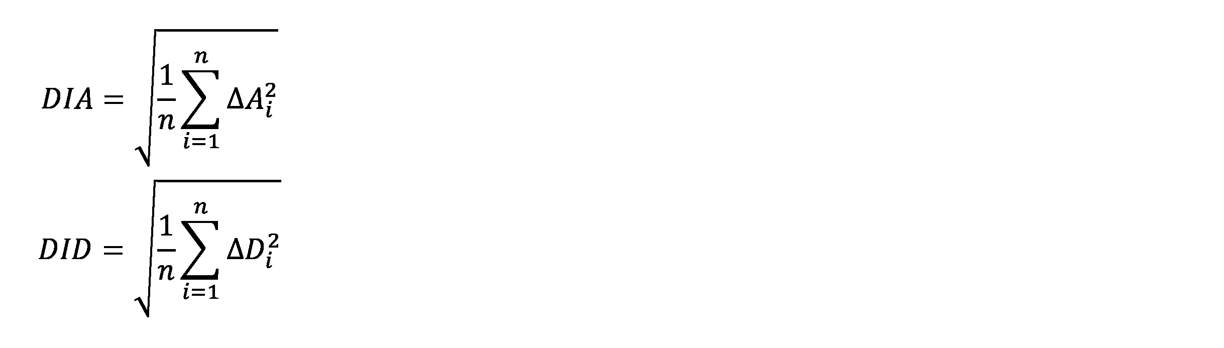
DIA :視方向の差に基づく評価指数
DID :深度の差に基づく評価指数
ΔAi :評価点P毎の|sinαi|
ΔDi :評価点P毎の、見かけ上の位置P’から両眼中点Oまでの距離の逆数Diと、基準位置P0から両眼中点Oまでの距離の逆数Di0との差(すなわち、Di-Di0)
である。
なお、仮想空間の座標系は、XYZ直交座標系に限らず、方位角と深度で定義される座標系に代えてもよい。この場合、評価点P毎の位置は、例えばP(D,T,C)で表される。Dは、評価点Pの深度(深度は両眼中点Oからの距離の逆数)であり、Tは、縦方向方位角のタンジェント、Cは、横方向方位角のタンジェントである。深度D、縦方向方位角T、横方向方位角Cは、それぞれ、次式により示される。

縦方向方位角Tと横方向方位角Cを極座標に変換し、半径方位角のタンジェントをρとし、象限方位角をθとすると、ρ、θは、次式により示される。

評価点Pは、P(x,y,z)、P(D,T,C)、P(D,ρ,θ)の何れで示すこともできる。すなわち、評価点Pの点列は、xyz座標系において例えば各軸等間隔又は不均等な間隔でサンプリングすることができ、また、D-T-C座標系において各軸等間隔又は不均等な間隔でサンプリングすることもでき、D-ρ-θ座標系において各軸等間隔又は不均等な間隔でサンプリングすることもできる。
なお、上記式(1)において、nを、眼鏡レンズ前方の空間に並ぶ評価点Pのサンプル数とし、ΔDiを、この空間に並ぶ評価点P毎の位置の差ΔD(x,y,z)とすると、評価指数DIは、眼鏡レンズを介した前方空間の見え方を評価する評価結果となる。
評価範囲である前方空間が直方体の空間である場合、上記式(1)をより具体的な次式に置換することができる。

nx :前方空間内のX軸方向に並ぶ評価点Pのサンプル数
ny :前方空間内のY軸方向に並ぶ評価点Pのサンプル数
nz :前方空間内のZ軸方向に並ぶ評価点Pのサンプル数
ΔAijk:前方空間内に設定される評価点P毎の視方向の差ΔA(x,y,z)
ΔDijk:前方空間内に設定される評価点P毎の深度の差ΔD(x,y,z)
(各方向において評価点Pは等間隔又は不均等な間隔で配置)
評価範囲である前方空間が両眼中点Oを頂点とする四角錐又は円錐の空間である場合、上記式(1)をより具体的な次式に置換することができる。
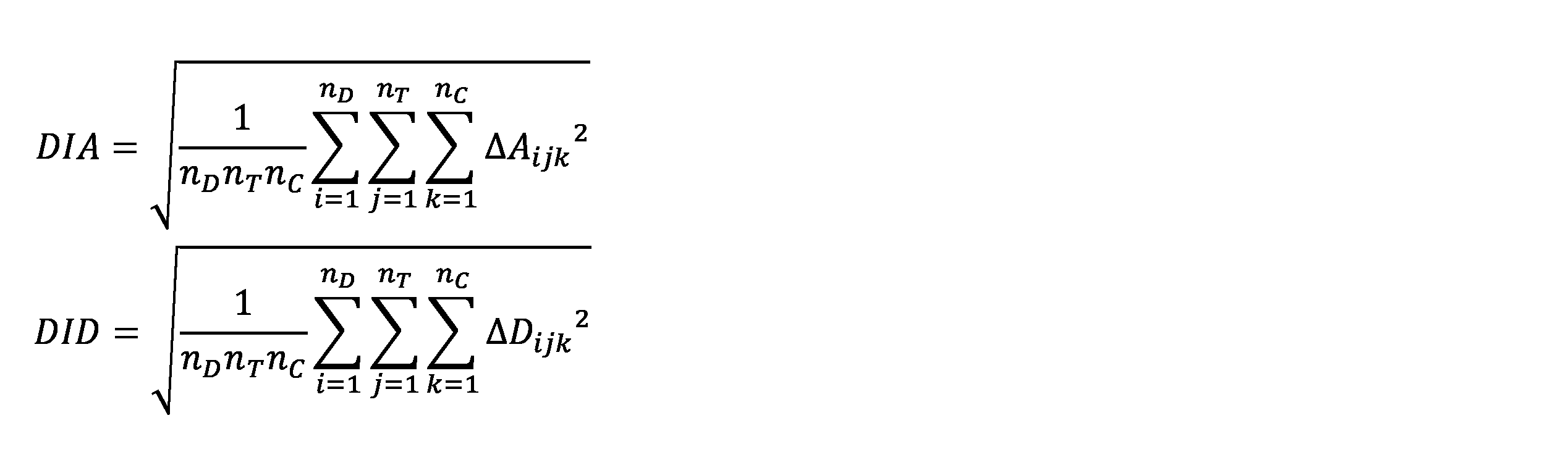
nD :前方空間内の深度方向に並ぶ評価点Pのサンプル数
nT :前方空間内の縦方向方位角の方向に並ぶ評価点Pのサンプル数
nC :前方空間内の横方向方位角の方向に並ぶ評価点Pのサンプル数
ΔAijk:前方空間内に設定される評価点P毎の視方向の差ΔA(D,T,C)
ΔDijk:前方空間内に設定される評価点P毎の深度の差ΔD(D,T,C)
(各方向において評価点Pは等間隔又は不均等な間隔で配置)
評価範囲である前方空間が両眼中点Oを頂点とする円錐の空間である場合、上記式(1)をより具体的な次式に置換することもできる。

nρ :前方空間内の半径方位角の方向に並ぶ評価点Pのサンプル数
nθ :前方空間内の象限方位角の方向に並ぶ評価点Pのサンプル数
ΔAijk:前方空間内に設定される評価点P毎の視方向の差ΔA(D,ρ,θ)
ΔDijk:前方空間内に設定される評価点P毎の深度の差ΔD(D,ρ,θ)
(各方向において評価点Pは等間隔又は不均等な間隔で配置)
前方空間内に配置された全ての評価点Pを統計して評価指数が算出されてもよいが、前方空間内に配置された一部の評価点Pに対して評価指数が算出されてもよい。
評価指数DI(又は評価指数DIA、DID)は、基準状態に対する眼鏡レンズ装用時の視野の変化を定量化して示す指標である。評価指数DIの値が大きいほど、基準状態に対する視野の変化が大きいという評価になる。評価指数DI(又は評価指数DIA、DID)は、設定された固視点FPを眼鏡レンズ上の視線通過位置FP’を通して固視した状態で、周囲の評価点Pの基準位置P0からの乖離を評価の対象として含めた指標となっている。すなわち、評価指数DIは、中心窩だけでなく中心窩以外の網膜周辺部でとらえた像も考慮した評価内容となっている。そのため、例えば、中心窩以外の網膜周辺部でとらえた像の歪み等(言い換えると、視野内の周辺部の像の歪み等)を不快に感じやすい患者に対し、例えば評価指数DI(又は評価指数DIA、DID)の値が小さい眼鏡レンズを提案することにより、その患者が納得する眼鏡レンズを提供することが可能となる。
具体的実施例を2つ説明する。実施例1では、評価範囲が眼鏡レンズの前方空間であり、実施例2では、評価範囲が両眼中点Oから特定の距離離れた平面である。実施例1、2の何れにおいても、評価対象は、遠近両用累進屈折力レンズであり、基準状態は裸眼状態である。
評価対象の遠近両用累進屈折力レンズは、実施例1と実施例2で共通である。この遠近両用累進屈折力レンズの仕様は次のとおりである。
右レンズ:S0.00D、ADD2.50D、累進帯長11mm
左レンズ:S0.00D、ADD2.50D、累進帯長11mm
遠用PD:64mm
前傾角 :0.0度
内傾角 :0.0度
CVD:14.5mm
左レンズ:S0.00D、ADD2.50D、累進帯長11mm
遠用PD:64mm
前傾角 :0.0度
内傾角 :0.0度
CVD:14.5mm
なお、CVD(Corneal Vertex Distance)は、眼鏡レンズの後方頂点と角膜の前面(角膜頂点)との距離である角膜頂点間距離である。
[実施例1]
実施例1では、両眼中点Oを頂点とする半径角50.2度の円錐空間(便宜上「円錐空間CS」と記す。)を評価範囲とする。円錐空間CSの深度の範囲は、0D~3.5D(言い換えると、無限遠距離から286mmまで)の範囲である。無限遠距離に設定された固視点FPへの視線が通過する眼鏡レンズ上の位置は、眼鏡レンズの幾何学中心から4mm上の位置である。円錐空間CS全体を評価範囲としたときの、眼鏡レンズ上の評価領域(言い換えると、円錐空間CS全体に配置された各評価点Pへの視線が通過する眼鏡レンズ上の範囲)は、幾何学中心を中心とした約φ40mmの範囲である。便宜上、眼鏡レンズ上の評価領域を「レンズ評価領域EA」と記す。
実施例1では、両眼中点Oを頂点とする半径角50.2度の円錐空間(便宜上「円錐空間CS」と記す。)を評価範囲とする。円錐空間CSの深度の範囲は、0D~3.5D(言い換えると、無限遠距離から286mmまで)の範囲である。無限遠距離に設定された固視点FPへの視線が通過する眼鏡レンズ上の位置は、眼鏡レンズの幾何学中心から4mm上の位置である。円錐空間CS全体を評価範囲としたときの、眼鏡レンズ上の評価領域(言い換えると、円錐空間CS全体に配置された各評価点Pへの視線が通過する眼鏡レンズ上の範囲)は、幾何学中心を中心とした約φ40mmの範囲である。便宜上、眼鏡レンズ上の評価領域を「レンズ評価領域EA」と記す。
図8は、実施例1の眼鏡レンズ(遠近両用累進屈折力レンズ)装用時において、深度が0Dのときの左右眼の視差(言い換えると、両眼中点Oから無限遠距離にある平面OPを見たときの左右眼の視差)を示す図である。図9は、実施例1の眼鏡レンズ装用時において、深度が3.5Dのときの左右眼の視差(言い換えると、両眼中点Oから286mm離れた平面OPを見たときの左右眼の視差)を示す図である。図8、図9の各図中、丸印は、評価点Pを右眼で見たときの評価点Pの位置を示し、三角印は、評価点Pを左眼で見たときの評価点Pの位置を示す。両者の位置が離れるほど視差が大きいことを示す。図8、図9の各図中、縦軸は、円錐空間CS内における垂直方向の位置を示し、横軸は、円錐空間CS内における水平方向の位置を示す。図8、図9の各図中、垂直方向における評価点Pの位置(T=tan α)及び水平方向における評価点Pの位置(C=tan β)は、タンジェントの値で示される。
深度、縦方向方位角、横方向方位角の各方向において、評価点Pは、等間隔で配置される。深度方向については、0.5D間隔(ΔD=0.5)で配置され、縦方向方位角及び横方向方位角の各方向については、0.15間隔(ΔT=0.15、ΔC=0.15)で配置される。円錐空間CS内に設定される評価点Pの総数は、1548である。
図8では、各評価点Pの右眼網膜位置を表す丸印と左眼網膜位置を表す三角印が、レンズの上半分においてほぼ重複していて(同じ位置にあり)、視差がゼロに近い。レンズ下半分では若干視差が生じている。図9では、物体距離が286mmと近いことから、視差の大きさが評価点P毎に比較的異なっており、また、レンズの上半分より、レンズの下半分の方が若干視差が大きい。
なお、眼鏡レンズ装用時の視差が視野内の周辺部で特に大きくなっていることを示す都合上、図9中、3つの評価点Pについて矢印マークを付記する。この矢印マークは、左眼で見たときの位置から右眼で見たときの位置に向かう矢印を示すマークとなっている。
図8、図9に示される視差情報を用いて、各評価点Pの見かけ上の位置P’を前述の方法で算出し、深度の差ΔDと視方向の差ΔAを指定範囲(評価対象となる空間)で統計することができる。円錐空間CS全体を評価範囲とした場合、評価点数は、1548であり、深度差に基づく評価指数DIDは、0.0857であり、視方向差に基づく評価指数DIAは、0.0326である。円錐空間CSのうち、レンズ評価領域EAの上半分の領域(便宜上「レンズ評価領域EAU」と記す。)を通過する各視線の先にある評価点P(総数:600)が配置される空間を評価範囲とした場合、評価指数DIDは、0.0586であり、評価指数DIAは、0.0097である。円錐空間CSのうち、レンズ評価領域EAの下半分の領域(便宜上「レンズ評価領域EAD」と記す。)を通過する各視線の先にある評価点P(総数:948)が配置される空間を評価範囲とした場合、評価指数DIDは、0.0991であり、評価指数DIAは、0.0409である。
円錐空間CS内において深度が0D(無限遠方物体)となる評価点Pのみを評価範囲(評価点Pの総数:192)とした場合、評価指数DIDは、0.0393であり、評価指数DIAは、0.0322である。レンズ評価領域EAUを通過する各視線の先にある、深度が0Dの評価点P(総数:75)が配置される範囲を評価範囲とした場合、評価指数DIDは、0.0052であり、評価指数DIAは、0.0097である。レンズ評価領域EADを通過する各視線の先にある、深度が0Dの評価点P(総数:117)が配置される範囲を評価範囲とした場合、評価指数DIDは、0.0501であり、評価指数DIAは、0.0405である。
円錐空間CS内において深度が3.5D(286mm)となる評価点Pのみを評価範囲(評価点Pの総数:196)とした場合、評価指数DIDは、0.1385であり、評価指数DIAは、0.0335である。レンズ評価領域EAUを通過する各視線の先にある、深度が3.5Dの評価点P(総数:75)が配置される範囲を評価範囲とした場合、評価指数DIDは、0.0970であり、評価指数DIAは、0.0099である。レンズ評価領域EADを通過する各視線の先にある、深度が3.5Dの評価点P(総数:121)が配置される範囲を評価範囲とした場合、評価指数DIDは、0.1588であり、評価指数DIAは、0.0419である。
実施例1にて算出される評価指数DIDから、遠近両用累進屈折力レンズでは、装用者が前方無限遠(ほぼ正面)を固視する状況において、物体距離が近いほど見かけ上の位置の深度と基準位置との差が大きくなる傾向にあることが判る。また、レンズ評価領域EAUよりもレンズ評価領域EAD(言い換えると、遠用部よりも近用部)を通して見たときの方が、見かけ上の位置の深度と基準位置との差が大きくなる傾向にあることが判る。一方、実施例1にて算出される評価指数DIAからは、評価点の深度に関係なく、レンズ評価領域EAUよりもレンズ評価領域EAD(言い換えると、遠用部よりも近用部)を通して見たときの方が、見かけ上の位置の視方向と基準位置との差が大きくなる傾向にあることが判る。
[実施例2]
実施例2では、遠近両用累進屈折力レンズの近用部を通して、新聞紙を広げてみる状況(図10)を評価する。固視点FPは、両眼中点Oから40cm離れた距離にある。近用部(具体的には、レンズの幾何学中心から11mm下方の位置)を通して見るため、固視点FPは、眼よりもやや斜め下方にある。両眼中点Oから固視点FPまでの直線に垂直な平面OPが新聞紙の紙面(平面)と設定され、この平面に評価点Pが設定される。具体的には、水平方向が80cmで垂直方向が40cmの矩形の平面が評価範囲である。評価点Pは、0.1間隔(ΔT=0.1、ΔC=0.1)で配置される。なお、図10では、便宜上、両眼中点Oを中心とする眼球モデルを図示する。
実施例2では、遠近両用累進屈折力レンズの近用部を通して、新聞紙を広げてみる状況(図10)を評価する。固視点FPは、両眼中点Oから40cm離れた距離にある。近用部(具体的には、レンズの幾何学中心から11mm下方の位置)を通して見るため、固視点FPは、眼よりもやや斜め下方にある。両眼中点Oから固視点FPまでの直線に垂直な平面OPが新聞紙の紙面(平面)と設定され、この平面に評価点Pが設定される。具体的には、水平方向が80cmで垂直方向が40cmの矩形の平面が評価範囲である。評価点Pは、0.1間隔(ΔT=0.1、ΔC=0.1)で配置される。なお、図10では、便宜上、両眼中点Oを中心とする眼球モデルを図示する。
図11は、図8や図9と同様の図であって、実施例2の眼鏡レンズ(遠近両用累進屈折力レンズ)装用時において、斜め下方に配置された平面OPを見たときの左右眼の視差を示す図である。実施例2では、平面OP全体を評価範囲とした場合、評価指数DIDは、0.1165であり、評価指数DIAは、0.0350である。なお、図11にも、図9と同様の矢印マークを付記する。
図11を参照すると、実施例2の遠近両用累進屈折力レンズでは、装用者が斜め下方の近距離を見る状況(例えば装用者が新聞や書籍を読む状況や、ノートPCやタブレット端末の画面を見る状況)において、固視点FPから離れた、視野内の周辺部で裸眼状態に対する左右眼の視差が大きくなっていることが判る。この評価指数DID及びDIAを受け、眼鏡レンズを提供する側は、例えば視野内の周辺部の像の歪み等を不快に感じやすい患者に対し、例えば斜め下方の近距離を見る状況にて視野内の周辺部で像の歪み等が少ない眼鏡レンズを提案することができる。
以上が本発明の例示的な実施形態の説明である。本発明の実施形態は、上記に説明したものに限定されず、本発明の技術的思想の範囲において様々な変形が可能である。例えば明細書中に例示的に明示される実施形態等又は自明な実施形態等を適宜組み合わせた内容も本願の実施形態に含まれる。
Claims (6)
- 評価対象となる空間上の特定位置を固視点と設定し、左右一対の眼鏡レンズを装用して前記固視点を固視する際のレンズ上の視線通過位置を設定する固視位置設定部と、
前記空間上に設定された複数の評価点の各々に対し、前記左右一対の眼鏡レンズ装用し且つ前記視線通過位置を通して前記固視点を固視する状態での、前記見かけ上の位置を算出する見かけ位置算出部と、
前記複数の評価点の各々について、前記算出された見かけ上の位置と、前記評価点の基準位置との差分を算出する差分算出部と、
前記差分算出部により算出された評価点毎の前記差分を統計した評価指数を算出する評価指数算出部と、
を備える、
眼鏡レンズの評価装置。 - 前記評価指数算出部は、次式を用いて前記評価指数を算出する、
但し、
DI :前記評価指数
n :前記空間上に設定される評価点のサンプル数
Δi :前記評価点毎の前記見かけ上の位置と前記基準位置との差分
である、
請求項1に記載の眼鏡レンズの評価装置。 - 前記評価点毎の前記見かけ上の位置と前記基準位置との差分は、次式により定義される、
Δi=Di-Di0
但し、
Di:前記評価点毎の前記見かけ上の位置から両眼中点までの距離の逆数
Di0:前記評価点毎の前記基準位置から前記両眼中点までの距離の逆数
である、
請求項2に記載の眼鏡レンズの評価装置。 - 前記評価点毎の前記見かけ上の位置と前記基準位置との差分は、次式により定義される、
Δi=|sinαi|
但し、
αi:前記評価点毎の前記見かけ上の位置から両眼中点へのベクトルと、前記評価点毎の前記基準位置から前記両眼中点へのベクトルと、がなす角度
である、
請求項2に記載の眼鏡レンズの評価装置。 - 前記基準位置は、
前記空間上に設定された評価点の位置そのものである、
請求項1から請求項4の何れか一項に記載の眼鏡レンズの評価装置。 - 前記眼鏡レンズが単焦点レンズ以外のレンズであり、
前記基準位置は、
前記眼鏡レンズと同じ度数を持つ単焦点レンズを装用したときの見かけ上の位置である、
請求項1から請求項4の何れか一項に記載の眼鏡レンズの評価装置。
Priority Applications (2)
| Application Number | Priority Date | Filing Date | Title |
|---|---|---|---|
| US17/912,678 US12366503B2 (en) | 2020-03-31 | 2021-03-17 | Eyeglasses lens evaluation device |
| EP21780335.2A EP4137879A4 (en) | 2020-03-31 | 2021-03-17 | DEVICE FOR EVALUATING A SPECTACULAR LENS |
Applications Claiming Priority (2)
| Application Number | Priority Date | Filing Date | Title |
|---|---|---|---|
| JP2020063166A JP7595424B2 (ja) | 2020-03-31 | 2020-03-31 | 眼鏡レンズの評価装置 |
| JP2020-063166 | 2020-03-31 |
Publications (1)
| Publication Number | Publication Date |
|---|---|
| WO2021200133A1 true WO2021200133A1 (ja) | 2021-10-07 |
Family
ID=77929172
Family Applications (1)
| Application Number | Title | Priority Date | Filing Date |
|---|---|---|---|
| PCT/JP2021/010715 Ceased WO2021200133A1 (ja) | 2020-03-31 | 2021-03-17 | 眼鏡レンズの評価装置 |
Country Status (4)
| Country | Link |
|---|---|
| US (1) | US12366503B2 (ja) |
| EP (1) | EP4137879A4 (ja) |
| JP (1) | JP7595424B2 (ja) |
| WO (1) | WO2021200133A1 (ja) |
Citations (8)
| Publication number | Priority date | Publication date | Assignee | Title |
|---|---|---|---|---|
| JP2002107679A (ja) * | 2000-09-28 | 2002-04-10 | Tokai Kogaku Kk | レンズの性能評価方法 |
| JP2003177076A (ja) * | 2001-09-06 | 2003-06-27 | Hoya Corp | 眼鏡レンズの両眼視性能表示方法及びその装置 |
| JP4481093B2 (ja) | 2004-06-23 | 2010-06-16 | Hoya株式会社 | 眼鏡レンズの性能評価方法及び眼鏡レンズの設計方法 |
| WO2010087450A1 (ja) * | 2009-01-30 | 2010-08-05 | Hoya株式会社 | 眼鏡レンズの評価方法、眼鏡レンズの設計方法、及び眼鏡レンズの製造方法 |
| JP2015094917A (ja) * | 2013-11-14 | 2015-05-18 | 株式会社ニコン | 眼鏡レンズ評価方法、眼鏡レンズ、眼鏡レンズ製造方法および表示方法 |
| JP2018109785A (ja) * | 2012-06-29 | 2018-07-12 | エシロール アンテルナシオナル (コンパニー ジェネラル ドプティック) | 装着者の利き手を考慮に入れた眼用レンズ |
| JP2018530787A (ja) * | 2015-10-15 | 2018-10-18 | エシロール・アンテルナシオナル | 眼科用レンズの3次元性能を判定する方法と、これに関連する眼科用レンズの計算方法 |
| WO2019068586A1 (en) * | 2017-10-03 | 2019-04-11 | Essilor International | METHOD FOR EVALUATING AN OPHTHALMIC LENS; ASSOCIATED ASSESSMENT SYSTEM AND INDUSTRIAL ASSEMBLY FOR MANUFACTURING AN OPHTHALMIC LENS |
Family Cites Families (22)
| Publication number | Priority date | Publication date | Assignee | Title |
|---|---|---|---|---|
| ATE308743T1 (de) | 2000-04-11 | 2005-11-15 | Hoya Corp | Darstellung der leistung eines brillenglases durch eine indexanzeige in visuell verständlicher weise |
| JP3919069B2 (ja) | 2000-04-11 | 2007-05-23 | Hoya株式会社 | 眼鏡レンズ性能表示方法及び装置 |
| JP4199000B2 (ja) * | 2001-03-15 | 2008-12-17 | エイエムオー・ウェーブフロント・サイエンシーズ・リミテッド・ライアビリティ・カンパニー | 光学システムをマッピングするための断層撮影波面分析システム及び方法 |
| EP1291633B1 (en) | 2001-09-06 | 2005-09-28 | Hoya Corporation | Method for evaluating binocular performance of spectacle lenses, method for displaying said performance and apparatus therefore |
| US6682195B2 (en) * | 2001-10-25 | 2004-01-27 | Ophthonix, Inc. | Custom eyeglass manufacturing method |
| JP4301399B2 (ja) | 2003-09-11 | 2009-07-22 | Hoya株式会社 | 眼鏡レンズの性能評価方法及び眼鏡レンズの設計方法 |
| FR2874709B1 (fr) * | 2004-08-27 | 2006-11-24 | Essilor Int | Procede de determination d'une paire de lentilles ophtalmiques progressives |
| FR2894688B1 (fr) * | 2005-12-13 | 2008-02-15 | Essilor Int | Procede de determination d'un jeu de lentilles ophtalmiques multifocales progressives. |
| BRPI1007918A2 (pt) * | 2009-02-05 | 2016-02-23 | Hoya Corp | métodos de projeto de lente de óculos, de avaliação de lente de óculos, e de fabricação de lente de óculos, sistema de fabricação de lente de óculos, e, lentes de óculos |
| EP2325618A1 (en) * | 2009-11-18 | 2011-05-25 | ESSILOR INTERNATIONAL (Compagnie Générale d'Optique) | Method for determining binocular performance of a pair of spectacle lenses |
| EP2600186A4 (en) * | 2010-07-27 | 2015-04-15 | Hoya Corp | METHOD FOR EVALUATING GLASS OF GLASSES, METHOD FOR DESIGNING GLASS OF GLASSES, METHOD FOR MANUFACTURING GLASS OF GLASSES, AND GLASS OF GLASSES |
| DE102011054833A1 (de) * | 2010-10-29 | 2012-05-03 | Hoya Corp. | Verfahren zum Messen der binokularen Sehleistung, Programm zum Messen der binokularen Sehleistung, Verfahren zum Entwerfen von Brillengläsern und Verfahren zur Herstellung von Brillengläsern |
| JP5475893B2 (ja) * | 2011-05-20 | 2014-04-16 | パナソニック株式会社 | 視覚疲労度測定装置およびその方法 |
| WO2014001490A1 (en) | 2012-06-29 | 2014-01-03 | Essilor International (Compagnie Generale D'optique) | A process for determining a pair of progressive ophthalmic lenses |
| JP2014103585A (ja) * | 2012-11-21 | 2014-06-05 | Toshiba Corp | 立体画像表示装置 |
| US20160198942A1 (en) * | 2012-12-31 | 2016-07-14 | Amo Development, Llc | Vergence weighting systems and methods for treatment of presbyopia and other vision conditions |
| US10365716B2 (en) * | 2013-03-15 | 2019-07-30 | Interaxon Inc. | Wearable computing apparatus and method |
| CN107567595B (zh) | 2015-06-08 | 2021-05-25 | 依视路国际公司 | 用于修改光学系统的非屈光参数的方法 |
| JP6991135B2 (ja) | 2015-10-15 | 2022-01-12 | エシロール・アンテルナシオナル | 累進レンズの光学系を判定する方法 |
| CN115542572B (zh) | 2018-06-28 | 2025-08-12 | 豪雅镜片泰国有限公司 | 渐进屈光力镜片 |
| AU2019309513C1 (en) * | 2018-07-26 | 2023-04-27 | Oakley, Inc. | Lens for eyewear and other headworn supports having improved optics |
| CN114930227B (zh) * | 2019-12-20 | 2024-09-27 | 株式会社尼康依视路 | 眼镜镜片的设计方法、眼镜镜片的制造方法、眼镜镜片、眼镜镜片设计装置、眼镜镜片订购及接受订购系统以及设计程序 |
-
2020
- 2020-03-31 JP JP2020063166A patent/JP7595424B2/ja active Active
-
2021
- 2021-03-17 WO PCT/JP2021/010715 patent/WO2021200133A1/ja not_active Ceased
- 2021-03-17 EP EP21780335.2A patent/EP4137879A4/en active Pending
- 2021-03-17 US US17/912,678 patent/US12366503B2/en active Active
Patent Citations (8)
| Publication number | Priority date | Publication date | Assignee | Title |
|---|---|---|---|---|
| JP2002107679A (ja) * | 2000-09-28 | 2002-04-10 | Tokai Kogaku Kk | レンズの性能評価方法 |
| JP2003177076A (ja) * | 2001-09-06 | 2003-06-27 | Hoya Corp | 眼鏡レンズの両眼視性能表示方法及びその装置 |
| JP4481093B2 (ja) | 2004-06-23 | 2010-06-16 | Hoya株式会社 | 眼鏡レンズの性能評価方法及び眼鏡レンズの設計方法 |
| WO2010087450A1 (ja) * | 2009-01-30 | 2010-08-05 | Hoya株式会社 | 眼鏡レンズの評価方法、眼鏡レンズの設計方法、及び眼鏡レンズの製造方法 |
| JP2018109785A (ja) * | 2012-06-29 | 2018-07-12 | エシロール アンテルナシオナル (コンパニー ジェネラル ドプティック) | 装着者の利き手を考慮に入れた眼用レンズ |
| JP2015094917A (ja) * | 2013-11-14 | 2015-05-18 | 株式会社ニコン | 眼鏡レンズ評価方法、眼鏡レンズ、眼鏡レンズ製造方法および表示方法 |
| JP2018530787A (ja) * | 2015-10-15 | 2018-10-18 | エシロール・アンテルナシオナル | 眼科用レンズの3次元性能を判定する方法と、これに関連する眼科用レンズの計算方法 |
| WO2019068586A1 (en) * | 2017-10-03 | 2019-04-11 | Essilor International | METHOD FOR EVALUATING AN OPHTHALMIC LENS; ASSOCIATED ASSESSMENT SYSTEM AND INDUSTRIAL ASSEMBLY FOR MANUFACTURING AN OPHTHALMIC LENS |
Non-Patent Citations (1)
| Title |
|---|
| See also references of EP4137879A4 |
Also Published As
| Publication number | Publication date |
|---|---|
| JP2021162678A (ja) | 2021-10-11 |
| JP7595424B2 (ja) | 2024-12-06 |
| EP4137879A1 (en) | 2023-02-22 |
| US12366503B2 (en) | 2025-07-22 |
| US20230152182A1 (en) | 2023-05-18 |
| EP4137879A4 (en) | 2024-05-15 |
Similar Documents
| Publication | Publication Date | Title |
|---|---|---|
| JP5615556B2 (ja) | オルト位置のための基準点 | |
| CN106133584B (zh) | 用于增强现实的系统和方法 | |
| JP6563918B2 (ja) | 眼科用累進レンズ用の少なくとも1つの光学設計パラメータの決定方法 | |
| JP6332392B2 (ja) | 眼鏡レンズの設計方法、眼鏡レンズの製造方法、眼鏡レンズ選択装置および眼鏡レンズ選択方法 | |
| ES2965742T3 (es) | Método de determinación de al menos un parámetro de diseño óptico de una lente oftálmica progresiva | |
| US11740459B2 (en) | Head-mounted display and method for designing wide-focus lens to be used for the head-mounted display | |
| CN104220923B (zh) | 渐进屈光力镜片以及渐进屈光力镜片的设计方法 | |
| US11754856B2 (en) | Method for designing eyeglass lens, method for manufacturing eyeglass lens, eyeglass lens, eyeglass lens ordering device, eyeglass lens order receiving device, and eyeglass lens ordering and order receiving system | |
| JP2014042806A (ja) | 注視線測定方法、注視線測定装置、眼球回旋点測定方法及びアイポイント測定装置 | |
| CN104380178A (zh) | 用于确定一副渐进式眼镜片的方法 | |
| CN113613546B (zh) | 评估用于视觉任务的视觉设备的性能的装置和方法 | |
| JP5822483B2 (ja) | 眼鏡用レンズ | |
| JP7128904B2 (ja) | 単一視眼科レンズを決定する方法 | |
| WO2021200133A1 (ja) | 眼鏡レンズの評価装置 | |
| CN106405867A (zh) | 隐形眼镜及其加工方法 | |
| JP7405371B2 (ja) | ゲーミングレンズの設計方法 | |
| JP2013076933A (ja) | 累進屈折力レンズ及び累進屈折力レンズの製造方法 | |
| JP6364517B2 (ja) | 眼鏡レンズ設計方法および眼鏡レンズ製造方法 | |
| JP3328098B2 (ja) | 眼光学系のシミュレーション装置 | |
| JP6298231B2 (ja) | 眼鏡レンズ設計方法および眼鏡レンズ製造方法 | |
| JP2023138360A (ja) | 眼鏡装用時の視力のシミュレーション方法 | |
| JP2005010415A (ja) | 眼鏡枠に対する視線方向の決定方法および決定器具 | |
| JP2021156978A (ja) | 眼鏡 | |
| TW202101071A (zh) | 計算方法、影像生成方法、眼鏡鏡片之設計方法、眼鏡鏡片之製造方法、眼鏡鏡片、眼鏡鏡片之販賣方法、計算裝置及程式 | |
| JP2005010417A (ja) | 眼鏡調整における眼鏡枠の決定方法 |
Legal Events
| Date | Code | Title | Description |
|---|---|---|---|
| 121 | Ep: the epo has been informed by wipo that ep was designated in this application |
Ref document number: 21780335 Country of ref document: EP Kind code of ref document: A1 |
|
| NENP | Non-entry into the national phase |
Ref country code: DE |
|
| ENP | Entry into the national phase |
Ref document number: 2021780335 Country of ref document: EP Effective date: 20221031 |