WO2021200188A1 - 画像処理装置および方法、プログラム、並びに、画像処理システム - Google Patents
画像処理装置および方法、プログラム、並びに、画像処理システム Download PDFInfo
- Publication number
- WO2021200188A1 WO2021200188A1 PCT/JP2021/010984 JP2021010984W WO2021200188A1 WO 2021200188 A1 WO2021200188 A1 WO 2021200188A1 JP 2021010984 W JP2021010984 W JP 2021010984W WO 2021200188 A1 WO2021200188 A1 WO 2021200188A1
- Authority
- WO
- WIPO (PCT)
- Prior art keywords
- image
- restored
- restoration
- area
- pixel
- Prior art date
- Legal status (The legal status is an assumption and is not a legal conclusion. Google has not performed a legal analysis and makes no representation as to the accuracy of the status listed.)
- Ceased
Links
Images

















Classifications
-
- G—PHYSICS
- G06—COMPUTING OR CALCULATING; COUNTING
- G06V—IMAGE OR VIDEO RECOGNITION OR UNDERSTANDING
- G06V20/00—Scenes; Scene-specific elements
- G06V20/60—Type of objects
- G06V20/64—Three-dimensional [3D] objects
-
- G—PHYSICS
- G06—COMPUTING OR CALCULATING; COUNTING
- G06F—ELECTRIC DIGITAL DATA PROCESSING
- G06F21/00—Security arrangements for protecting computers, components thereof, programs or data against unauthorised activity
- G06F21/60—Protecting data
- G06F21/62—Protecting access to data via a platform, e.g. using keys or access control rules
- G06F21/6218—Protecting access to data via a platform, e.g. using keys or access control rules to a system of files or objects, e.g. local or distributed file system or database
- G06F21/6245—Protecting personal data, e.g. for financial or medical purposes
-
- G—PHYSICS
- G06—COMPUTING OR CALCULATING; COUNTING
- G06T—IMAGE DATA PROCESSING OR GENERATION, IN GENERAL
- G06T5/00—Image enhancement or restoration
-
- G—PHYSICS
- G06—COMPUTING OR CALCULATING; COUNTING
- G06T—IMAGE DATA PROCESSING OR GENERATION, IN GENERAL
- G06T5/00—Image enhancement or restoration
- G06T5/20—Image enhancement or restoration using local operators
-
- G—PHYSICS
- G06—COMPUTING OR CALCULATING; COUNTING
- G06V—IMAGE OR VIDEO RECOGNITION OR UNDERSTANDING
- G06V40/00—Recognition of biometric, human-related or animal-related patterns in image or video data
- G06V40/10—Human or animal bodies, e.g. vehicle occupants or pedestrians; Body parts, e.g. hands
- G06V40/16—Human faces, e.g. facial parts, sketches or expressions
-
- H—ELECTRICITY
- H04—ELECTRIC COMMUNICATION TECHNIQUE
- H04N—PICTORIAL COMMUNICATION, e.g. TELEVISION
- H04N23/00—Cameras or camera modules comprising electronic image sensors; Control thereof
- H04N23/60—Control of cameras or camera modules
- H04N23/61—Control of cameras or camera modules based on recognised objects
- H04N23/611—Control of cameras or camera modules based on recognised objects where the recognised objects include parts of the human body
-
- H—ELECTRICITY
- H04—ELECTRIC COMMUNICATION TECHNIQUE
- H04N—PICTORIAL COMMUNICATION, e.g. TELEVISION
- H04N23/00—Cameras or camera modules comprising electronic image sensors; Control thereof
- H04N23/60—Control of cameras or camera modules
- H04N23/63—Control of cameras or camera modules by using electronic viewfinders
- H04N23/633—Control of cameras or camera modules by using electronic viewfinders for displaying additional information relating to control or operation of the camera
- H04N23/635—Region indicators; Field of view indicators
-
- H—ELECTRICITY
- H04—ELECTRIC COMMUNICATION TECHNIQUE
- H04N—PICTORIAL COMMUNICATION, e.g. TELEVISION
- H04N23/00—Cameras or camera modules comprising electronic image sensors; Control thereof
- H04N23/95—Computational photography systems, e.g. light-field imaging systems
- H04N23/955—Computational photography systems, e.g. light-field imaging systems for lensless imaging
-
- H—ELECTRICITY
- H04—ELECTRIC COMMUNICATION TECHNIQUE
- H04N—PICTORIAL COMMUNICATION, e.g. TELEVISION
- H04N23/00—Cameras or camera modules comprising electronic image sensors; Control thereof
- H04N23/95—Computational photography systems, e.g. light-field imaging systems
- H04N23/957—Light-field or plenoptic cameras or camera modules
-
- G—PHYSICS
- G06—COMPUTING OR CALCULATING; COUNTING
- G06T—IMAGE DATA PROCESSING OR GENERATION, IN GENERAL
- G06T2207/00—Indexing scheme for image analysis or image enhancement
- G06T2207/20—Special algorithmic details
- G06T2207/20081—Training; Learning
-
- G—PHYSICS
- G06—COMPUTING OR CALCULATING; COUNTING
- G06T—IMAGE DATA PROCESSING OR GENERATION, IN GENERAL
- G06T2207/00—Indexing scheme for image analysis or image enhancement
- G06T2207/30—Subject of image; Context of image processing
- G06T2207/30196—Human being; Person
- G06T2207/30201—Face
Definitions
- the present technology relates to an image processing device, a method, a program, and an image processing system, and more particularly to an image processing device, a method, a program, and an image processing system capable of specifying an area to be restored.
- the image sensor is generally used in combination with an image sensor that concentrates on the image sensor.
- the image sensor guides the light from the subject surface to each pixel of the image sensor so as to reproduce the light intensity distribution of the subject surface, so that the image sensor detects a level corresponding to the light intensity distribution in each pixel.
- a signal can be obtained, and a captured image of the subject can be obtained as a whole.
- An image pickup device to which such an image pickup element is applied restores a restored image by, for example, performing a predetermined calculation on a detection image generated by the image pickup element.
- This disclosure was made in view of such a situation, and makes it possible to specify the area to be restored.
- the image processing device on one aspect of the present technology includes a plurality of pixels that receive incident light that is incident without passing through either an image pickup lens or a pinhole, and is an output pixel of at least two of the plurality of pixels.
- the restored image is obtained by using the restoration matrix in the region of the detected image obtained in the image sensor having a configuration for making the incident angle directivity of the value with respect to the incident light from the subject different from each other. It is an image processing device provided with an area specifying unit for specifying a restoration area to be restored.
- the image processing method of one aspect of the present technology includes a plurality of pixels that receive incident light that is incident without passing through either the image pickup lens or the pinhole, and the output pixels of at least two of the plurality of pixels.
- the restored image is obtained by using the restoration matrix in the region of the detected image obtained in the image sensor having a configuration for making the incident angle directivity of the value with respect to the incident light from the subject different from each other. This is an image processing method that specifies the restoration area to be restored.
- a program of one aspect of the present technology comprises a computer comprising a plurality of pixels that receive incident light incident light without passing through an image sensor or a pinhole, and outputs at least two of the plurality of pixels.
- a restored image using a restoration matrix in the region of the detected image obtained by an image sensor having a configuration for making the incident angle directivity of the pixel value with respect to the incident light from the subject different from each other. It is a program that functions as an area identification part that identifies the restoration area.
- An image processing system on another aspect of the present technology includes an image pickup device and an image processor, and the image pickup device includes a plurality of pixels that receive incident light that is incident without passing through either an image pickup lens or a pinhole.
- the image sensor is provided with a configuration for allowing the output pixel values of at least two of the plurality of pixels to have different characteristics from each other in the incident angle directivity with respect to the incident light from the subject.
- the image processing device is an image processing system including a region specifying unit that specifies a restored region for restoring a restored image using a restoration matrix in the region of the detected image obtained by the image sensor.
- the image processing apparatus and method of one aspect of the present technology, and the program include a plurality of pixels that receive incident light that is incident without passing through either an image pickup lens or a pinhole, and at least two of the plurality of pixels.
- the reconstruction matrix in the region of the detected image obtained in the image sensor having a configuration for making the incident angle directivity of the output pixel value of one pixel with respect to the incident light from the subject different from each other.
- the restored area for restoring the restored image is identified using.
- the image pickup device includes a plurality of pixels that receive incident light incident without passing through either an image pickup lens or a pinhole, and at least two of the plurality of pixels are provided.
- the subject is imaged by an image sensor having a configuration in which the incident angle directivity of the output pixel value of one pixel with respect to the incident light from the subject has different characteristics from each other.
- the restored region for restoring the restored image is specified by using the restoration matrix.
- the above-mentioned detected image is an image that cannot be recognized as an image even if the user visually recognizes it (that is, the subject cannot be visually recognized) because the image of the subject is not formed.
- a restored image is used from this detected image using a predetermined restoration matrix. Need to be restored. Since the area to be restored cannot be controlled as described above and the entire detected image is restored, there is a risk of information leakage or unauthorized use in the restored image as in the case of the captured image described above. In addition, it was not possible to control the disclosure range based on user privileges and the like.
- the restoration area for restoring the restored image includes a plurality of pixels that receive incident light that is incident without passing through either the image sensor or the pinhole, and the output pixel values of at least two of the plurality of pixels are incident on the incident light from the subject.
- the restored region for restoring the restored image is specified by using the restoration matrix. In other words, a non-restored area that does not restore the restored image is set for the detected image.
- the restoration matrix is used to identify a non-restoration region in which the restoration image is not restored, among the regions of the detection image obtained in the image sensor having a configuration for making the angular directional characteristics different from each other.
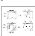
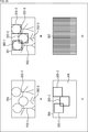
- the detection image 51 shown in FIG. 1A includes a plurality of pixels that receive incident light that is incident without passing through either the image pickup lens or the pinhole, and at least two of the plurality of pixels. It consists of a detection signal obtained from a pixel obtained by imaging the subject with an image sensor having a configuration for making the incident angle directivity of the output pixel value with respect to the incident light from the subject different from each other. It is an image. As shown in FIG. 1A, the detected image 51 cannot be recognized as an image even if the user visually recognizes it because the image of the subject is not formed (that is, the subject cannot be visually recognized). ) It is an image.
- the restored image 52 of B in FIG. 1 shows an example of the restored image restored from the detected image 51.
- a person 53-1, a person 53-2, and a person 53-3 are shown as subjects.
- the person 53-1 to the person 53-3 can be visually recognized as the subject.
- the person 53 is referred to as the person 53.
- the restored image 52 is released and the faces of each person 53 are made public, there is a risk of infringement of the portrait right.
- a non-restoration area including the face portion of each person 53 is set, and the restored image is restored.
- the restored image is restored by setting a region other than the non-restored area as the restored area.
- the restored image 54 shown in FIG. 1C shows an example of the restored image thus restored so as not to restore the non-restored area.
- the non-restored area 55-1 is a non-restored area set to include the face portion of the person 53-1.
- the non-restored area 55-2 is a non-restored area set to include the face portion of the person 53-2.
- the non-restored area 55-3 is a non-restored area set to include the face portion of the person 53-3.
- the non-restored area 55-1 to the non-restored area 55-3 are referred to as a non-restored area 55.
- these non-restored regions 55 are not restored and remain as detected images. That is, in the restored image 54, the face portion of each person 53 is invisible.
- the restored image can be made public while keeping the face part of each person 53 private. That is, by setting the restored area and the non-restored area, it is possible to control whether or not to restore an arbitrary area of the detected image. As a result, it is possible to control, for example, disclosure / non-disclosure of an arbitrary area of the detected image, and control of information protection / non-protection against unauthorized leakage or unauthorized use. Further, for example, it is possible to control the target range such as image analysis and control the level of the service to be provided.
- the restored area (or non-restored area) may be the entire area of the detected image. That is, the entire region of the detected image can be a restored region or a non-restored region.
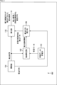
- FIG. 2 is a diagram showing a main configuration example of an image pickup apparatus which is an embodiment of an image processing apparatus to which the present technology is applied.
- the image pickup apparatus 100 shown in FIG. 2 is an apparatus that images a subject and obtains electronic data related to the captured image.
- the image pickup apparatus 100 includes ⁇ 1.
- the restored image non-restored area
- the restored image can be set for the detected image, and the restored image can be restored so as not to restore the non-restored area.
- FIG. 2 shows the main things such as the processing unit and the data flow, and not all of them are shown in FIG. That is, in the image pickup apparatus 100, there may be a processing unit that is not shown as a block in FIG. 2, or there may be a processing or data flow that is not shown as an arrow or the like in FIG.
- the image pickup apparatus 100 includes an image pickup unit 101, an area identification unit 102, a learning data storage unit 103, a restoration matrix update unit 104, a restoration unit 105, and the like.
- the image pickup unit 101 has an image pickup device 121, which will be described later, and performs processing related to generation of a detected image.
- the image pickup unit 101 can take an image of the subject and generate a detection image by the image pickup device 121.
- the image sensor 121 includes a plurality of pixel output units that receive incident light incident light without passing through either an image pickup lens or a pinhole, and the output pixel value of at least two pixel output units of the plurality of pixel output units. This is an image sensor having a configuration for making the incident angle directivity with respect to the incident light from the subject different from each other. Details of the image sensor 121 will be described later.
- the imaging unit 101 may supply the generated detection image to the region identification unit 102 and the restoration unit 105.
- the imaging unit 101 may supply the restoration matrix updating unit 104 corresponding to the detected image, that is, a restoration matrix used to generate the restored image from the detected image.
- This restoration matrix may be stored in advance by the imaging unit 101, or may be generated by the imaging unit 101.
- the angle of view of the image sensor 121 may be fixed or variable in the absolute coordinate system of the three-dimensional space.
- the position and orientation of the image sensor 121 (or the image pickup unit 101) may be fixed with respect to the image pickup device 100 or may be variable.
- the image pickup apparatus 100 may be fixed or variable in the absolute coordinate system of the three-dimensional space.
- the area specifying unit 102 performs processing related to specifying the restored area (or non-restored area). For example, the region specifying unit 102 can acquire the detected image supplied from the imaging unit 101. Further, the area specifying unit 102 can acquire the learning data stored in the learning data storage unit 103. Further, the area specifying unit 102 restores (or) the detected image supplied from the image pickup unit 101, that is, the detected image obtained by the image pickup device 121, based on the learning data read from the learning data storage unit 103. Non-restored area) can be set. Further, the area specifying unit 102 generates the restored area information (or the non-restored area information indicating the non-restored area) indicating the restored area, and supplies the restored area information to the restored matrix updating unit 104.
- the restored area information or the non-restored area information indicating the non-restored area
- the learning data storage unit 103 performs processing related to storage of learning data.
- the learning data storage unit 103 has an arbitrary storage medium and stores learning data relating to the identification of the restoration area. This learning data will be described later.
- the learning data storage unit 103 may supply the stored learning data to the area identification unit 102, for example, in response to a request from the area identification unit 102.
- the restoration matrix update unit 104 performs processing related to updating the restoration matrix.
- the restoration matrix update unit 104 may acquire the restoration area information (or non-restoration area information) supplied from the area identification unit 102.
- the restoration matrix updating unit 104 can acquire the restoration matrix supplied from the imaging unit 101.
- This restoration matrix is a restoration matrix (used for restoration of the restored image) corresponding to the detected image generated by the imaging unit 101.
- the restoration matrix update unit 104 updates the restoration matrix acquired from the imaging unit 101 based on the restoration area information, and restores only the restoration area without restoring the non-restoration area (corresponding to the non-restoration area). (Also called a recovery matrix) can be generated. That is, the restoration matrix update unit 104 is a partial restoration matrix generation unit that generates a partial restoration matrix used to restore only the restoration image of the specified restoration region from the detected image. This non-restored area is an area determined based on the restored area indicated by the restored area information, and is an area other than the restored area of the detected image.
- the restored matrix updating unit 104 updates the restored matrix acquired from the imaging unit 101 based on the non-restored area information, and the non-restored area information. It is possible to generate a non-restoration area corresponding restoration matrix for restoring only the restoration area without restoring the non-restoration area indicated by.
- This restored area is an area determined based on the non-restored area indicated by the non-restored area information, and is an area other than the non-restored area of the detected image.
- the restoration matrix update unit 104 can supply the restoration matrix corresponding to the non-restoration area, which is the restoration matrix after the update, to the restoration unit 105.
- the restoration matrix update unit 104 may set a partial restoration matrix (also referred to as a restoration matrix corresponding to a non-restoration region). For example, it is predetermined that the left half is not restored when a face is detected in the upper left of the detected image, and the restoration matrix is also a matrix that does not restore only the left half (a dedicated matrix when the left half is not restored).
- a face is detected in advance (for example, stored in a storage area in the restoration matrix update unit 104) and the restoration matrix update unit 104 detects a face in the upper left of the detection image based on the restoration area information.
- the restoration matrix update unit 104 may set whether or not to apply the restoration matrix corresponding to the non-restoration region prepared in advance without generating the restoration matrix corresponding to the non-restoration region.
- the restoration matrix update unit 104 selects one from a plurality of restoration matrices corresponding to the non-restoration area prepared in advance based on the restoration area information. And may be applied. That is, the restoration matrix update unit 104 can be said to be a partial restoration matrix setting unit that sets a partial restoration matrix used to restore only the restoration image of the specified restoration area from the detected image.
- the restoration unit 105 performs processing related to restoration of the restored image.
- the restoration unit 105 can acquire the detected image supplied from the imaging unit 101. Further, the restoration unit 105 can acquire the restoration matrix corresponding to the non-restoration region supplied from the restoration matrix update unit 104. Further, the restoration unit 105 can restore the restored image by using the restoration matrix corresponding to the non-restoration area. By this process, a restored image in which only the restored area is restored can be generated from the detected image. In addition, the restoration unit 105 can output the generated restored image (restored image in which only the restored area is restored from the detected image) to the outside of the image pickup apparatus 100. The restored image may be restored outside the imaging device 100.
- the restoration unit 105 does not perform this restoration, but associates the detected image with the restoration matrix corresponding to the non-restoration region and outputs the output to the restoration device outside the imaging device 100, which performs the restoration processing.
- the image pickup apparatus 100 can transmit the image to the restoration apparatus (another apparatus) in a state where the information is protected. Therefore, it is possible to suppress the occurrence of infringement of privacy rights due to unauthorized leakage or unauthorized use of images.
- the output of the information to the outside may be performed by communication via an arbitrary communication path, or may be performed via an arbitrary storage medium (that is, the information is stored in the storage medium and output). It may be.
- the term "associate" means, for example, to make the other information available (linkable) when processing one piece of information (data, commands, programs, etc.). That is, the information associated with each other may be collected as one file or the like, or may be individual information.
- the information B associated with the information A may be transmitted on a transmission path different from that of the information A. Further, for example, the information B associated with the information A may be recorded on a recording medium (or another recording area of the same recording medium) different from the information A.
- the area specifying unit 102 can control the area to be restored by specifying the restored area (non-restored area). As a result, the image pickup apparatus 100 can restore the restored image so as not to restore an arbitrary area.
- each of these processing units imaging unit 101 to restoring unit 105) of the imaging device 100 can have an arbitrary configuration.
- each processing unit may be configured by a logic circuit that realizes the above-mentioned processing.
- each processing unit has, for example, a CPU (Central Processing Unit), a ROM (Read Only Memory), a RAM (Random Access Memory), and the like, and the above-mentioned processing is realized by executing a program using them. You may do so.
- each processing unit may have both configurations, and a part of the above-mentioned processing may be realized by a logic circuit, and the other may be realized by executing a program.
- the configurations of the respective processing units may be independent of each other. For example, some processing units realize a part of the above-mentioned processing by a logic circuit, and some other processing units execute a program.
- the above-mentioned processing may be realized by the other processing unit by both the logic circuit and the execution of the program.
- pixel or “pixel output unit”.
- the "pixel” is independent of other pixels in a region (also referred to as a pixel region) in which a physical configuration for receiving incident light of the image sensor 121 is formed. It refers to a division unit including at least one physical configuration capable of receiving light.
- the physical configuration capable of receiving light is, for example, a photoelectric conversion element, for example, a photodiode (PD (Photo Diode)).
- PD Photo Diode
- the number of physical configurations (for example, photodiodes) formed in one pixel is arbitrary, and may be singular or plural. The type, size, shape, etc. are also arbitrary.
- each "pixel” includes, for example, an on-chip lens, a light-shielding film, a color filter, a flattening film, an antireflection film, and the like. Includes all physical configurations related to light reception. Further, a configuration such as a read circuit may be included. That is, the physical configuration of each pixel may be any configuration.
- the detection signal read from the "pixel” may be referred to as a "pixel unit (or pixel output unit) detection signal” or the like.
- the pixel unit (or pixel output unit) detection signal is also referred to as a “pixel unit detection signal (or pixel output unit detection signal)”.
- this pixel unit detection signal is also referred to as "pixel output”.
- the value is also referred to as an "output pixel value”.
- the value of the detection signal (output pixel value) for each pixel of the image sensor 121 can have the incident angle directivity (characteristic with respect to the incident angle) of the incident light from the subject independently of the others. That is, each pixel unit (pixel output unit) of the image sensor 121 has a configuration in which the incident angle directivity of the output pixel value with respect to the incident light from the subject can be set independently. Therefore, in the image sensor 121, the output pixel values of at least two pixel units have different incident angle directivity with respect to the incident light from the subject.
- the pixel unit detection signal is a single "physical configuration capable of receiving light”. It may be the detection signal obtained by the above-mentioned, or it may be the detection signal obtained by a plurality of “physical configurations capable of receiving light”.
- the pixel unit detection signal (output pixel value) can be combined into one at any stage.
- the output pixel values of a plurality of pixels may be added in the state of an analog signal, or may be converted into a digital signal and then added.
- a plurality of detection signals can be collectively singularized, or a single detection signal can be singularized. That is, the resolution (number of data) of the detected image is variable.
- the image sensor 121 will be described as having a pixel region in which a plurality of pixels are arranged in a matrix (a pixel array is formed).
- the arrangement pattern of the pixels (or pixel output units) of the image sensor 121 is arbitrary and is not limited to this example.
- the pixels (or pixel output units) may be arranged in a honeycomb structure.
- the pixels (or pixel output units) may be arranged in one row (or one column). That is, the image sensor 121 may be a line sensor.
- the wavelength range in which the image sensor 121 (pixels) has sensitivity is arbitrary.
- the image pickup device 121 (pixels) may be sensitive to visible light, or may be sensitive to invisible light such as infrared light or ultraviolet light. It may be sensitive to both visible and invisible light.
- the image sensor 121 has a plurality of pixel output units.
- the image sensor 121 is used to ensure that the directivity of the output pixel values of at least two pixel output units of the plurality of pixel output units with respect to the incident light from the subject has different characteristics from each other.
- the angular directivity is different from each other.
- the “incident angle directivity” refers to the light receiving sensitivity characteristic according to the incident angle of the incident light, that is, the detection sensitivity with respect to the incident angle of the incident light. For example, even if the incident light has the same light intensity, the detection sensitivity may change depending on the incident angle. Such a bias in detection sensitivity (including the case where there is no bias) is referred to as “incident angle directivity”.
- the signal levels (detection signal levels) of the detection signals of each pixel output unit are different from each other.
- the image sensor 121 each pixel output unit of the image sensor 121) has a physical configuration having such characteristics.
- the image pickup device 121 may have a basic structure similar to that of a general image pickup device such as a CMOS (Complementary Metal Oxide Semiconductor) image sensor.
- CMOS Complementary Metal Oxide Semiconductor
- This incident angle directivity may be realized by any method.
- the incident angle directivity may be realized by providing a light-shielding film in front of the photoelectric conversion element (photodiode or the like) (light incident side).
- an image pickup lens or a pinhole is provided in front of the image sensor (on the light incident side).
- the image sensor can obtain a detection signal at a level corresponding to the image of the imaged subject in each pixel (that is, an image of the imaged subject can be obtained).
- the size is physically increased, which may make it difficult to miniaturize the device.
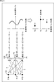
- the image sensor 121 has incident angle directivity in which the detection sensitivities of the pixels are different from each other, as shown in the upper left part of FIG. That is, the light receiving sensitivity characteristic according to the incident angle of the incident light is different for each pixel.
- the light-receiving sensitivity characteristics of all the pixels do not have to be completely different, and some pixels may include those having the same light-receiving sensitivity characteristics, or some pixels may have different light-receiving sensitivities. It may have characteristics.
- the image pickup element 121 Assuming that the light source constituting the subject surface 131 is a point light source, in the image pickup element 121, light rays having the same light intensity emitted from the same point light source are incident on all the pixels. However, each pixel is incident at a different incident angle. Since each pixel of the image sensor 121 has different incident angle directivity, the light rays having the same light intensity are detected with different sensitivities. That is, detection signals having different signal levels are detected for each pixel.
- the sensitivity characteristic according to the incident angle of the incident light received by each pixel of the image sensor 121 determines the light receiving sensitivity according to the incident angle. It shall be expressed by a coefficient to be expressed, and the signal level of the detection signal (also referred to as the detection signal level) according to the incident light in each pixel is multiplied by a coefficient set corresponding to the light receiving sensitivity according to the incident angle of the incident light. It will be what is required.
- the detection signal levels DA, DB, and DC at the positions Pa, Pb, and Pc are represented by the following equations (1) to (3), respectively. NS.
- DA ⁇ 1 ⁇ a + ⁇ 1 ⁇ b + ⁇ 1 ⁇ c ...
- DB ⁇ 2 ⁇ a + ⁇ 2 ⁇ b + ⁇ 2 ⁇ c ...
- DC ⁇ 3 ⁇ a + ⁇ 3 ⁇ b + ⁇ 3 ⁇ c ...
- ⁇ 1 is a coefficient set according to the incident angle of the light beam from the point light source PA on the subject surface 131 to be restored at the position Pa on the image sensor 121.
- ⁇ 1 is a coefficient set according to the incident angle of the light beam from the point light source PB on the subject surface 131 to be restored at the position Pa on the image sensor 121.
- ⁇ 1 is a coefficient set according to the incident angle of the light beam from the point light source PC on the subject surface 131 to be restored at the position Pa on the image sensor 121.
- the detection signal level DA at the position Pa is the product of the light intensity "a" of the light ray from the point light source PA at the position Pa and the coefficient ⁇ 1 and the point light source PB at the position Pa. It is expressed by the sum (composite value) of the product of the light intensity "b" of the light beam and the coefficient ⁇ 1 and the product of the light intensity "c” of the light ray from the point light source PC at the position Pa and the coefficient ⁇ 1.
- the coefficients ⁇ x, ⁇ x, and ⁇ x (x is a natural number) are collectively referred to as a coefficient set.
- the coefficient sets ⁇ 2, ⁇ 2, and ⁇ 2 of the equation (2) are set according to the incident angles of the light rays from the point light sources PA, PB, and PC on the subject surface 131 to be restored at the position Pb on the image pickup element 121.
- Coefficient set That is, the detection signal level DB at the position Pb is the product of the light intensity "a" of the light beam from the point light source PA at the position Pb and the coefficient ⁇ 2, and the point light source PB at the position Pb, as in the above equation (2).
- the coefficients ⁇ 3, ⁇ 3, and ⁇ 3 of the equation (3) are coefficients set according to the incident angle of the light rays from the point light sources PA, PB, and PC on the subject surface 131 to be restored at the position Pc on the image pickup element 121. It is a set.
- the detection signal level DC at the position Pc is the product of the light intensity "a” of the light beam from the point light source PA at the position Pc and the coefficient ⁇ 3, and the point light source PB at the position Pc, as in the above equation (3). It is expressed by the sum (composite value) of the product of the light intensity "b" of the light beam from the light source "b” and the coefficient ⁇ 3 and the product of the light intensity "c” of the light ray from the point light source PC at the position Pc and the coefficient ⁇ 3.
- these detection signal levels are different from those in which the image of the subject is imaged because the light intensities of the light rays emitted from the point light sources PA, PB, and PC are mixed. It is a thing. That is, since the detection signal level shown in the upper right part of FIG. 3 is not the detection signal level corresponding to the image (captured image) in which the image of the subject is formed, the pixel value shown in the lower right part of FIG. (Generally the two do not match).
- a simultaneous equation using the coefficient set ⁇ 1, ⁇ 1, ⁇ 1, the coefficient set ⁇ 2, ⁇ 2, ⁇ 2 coefficient set ⁇ 3, ⁇ 3, ⁇ 3 and the detection signal levels DA, DB, and DC is constructed, and a, b, and c are set.
- the image pickup device 121 has different incident angle directivity in at least two pixel output units without the need for an optical filter composed of an image pickup lens, a diffraction grating, or the like, a pinhole, or the like.
- an optical filter composed of an imaging lens, a diffraction grating, etc., a pinhole, etc. are not essential configurations, so that the height of the imaging device is reduced, that is, the thickness of light in a configuration that realizes an imaging function is reduced with respect to the incident direction. It becomes possible to do.
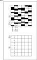
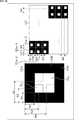
- FIG. 4 shows a front view of a part of the pixel array portion of a general image sensor
- the right portion of FIG. 4 shows a front view of a part of the pixel array portion of the image sensor 121.
- FIG. 4 shows an example in which the pixel array portion has a configuration in which the number of pixels in each of the horizontal direction and the vertical direction is 6 pixels ⁇ 6 pixels, but the configuration of the number of pixels is limited to this. is not it.
- the incident angle directivity can be formed by, for example, a light-shielding film.
- a light-shielding film In the general image sensor 151, as in the example on the left side of FIG. 4, it is shown that pixels 151a having the same incident angle directivity are arranged in an array.
- the image sensor 121 in the example on the right side of FIG. 4 is provided with a light-shielding film 121b in a different range for each pixel 121a, which is a part of the light receiving region of the photodiode.
- the light receiving sensitivity of the incident light with respect to the incident angle is different for each pixel 121a (that is, the incident angle directivity is different from each other).
- the range in which the pixel is shielded differs depending on the light-shielding film 121b-1 and the light-shielding film 121b-2 provided (the area (position) for shielding the pixel). ), And at least one of the shaded areas is different). That is, in the pixel 121a-1, a light-shielding film 121b-1 is provided so as to block a part of the left side in the light receiving region of the photodiode by a predetermined width, and in the pixel 121a-2, the right side in the light receiving region.
- a light-shielding film 121b-2 is provided so as to block a part of the light-shielding film 121b-1 by a width wider in the horizontal direction than the light-shielding film 121b-1.
- the light-shielding film 121b is provided so as to block light in a different range in the light receiving region for each pixel, and is randomly arranged in the pixel array.
- the range of the light-shielding film 121b is preferably set to an area where a desired amount of light can be secured because the amount of light that can be received decreases as the ratio of covering the light-receiving area of each pixel increases.
- the area of is limited to, for example, about 3/4 of the entire range in which light can be received at the maximum. By doing so, it is possible to secure a light amount equal to or greater than a desired amount.
- each pixel is provided with an unshielded range having a width corresponding to the wavelength of the light to be received, it is possible to receive the minimum amount of light. That is, for example, in the case of a B pixel (blue pixel), the wavelength is about 500 nm, but it is possible to receive the minimum amount of light as long as the light is not shielded by a width corresponding to this wavelength or more.
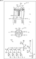
- FIG. 5 A configuration example of the image sensor 121 in this case will be described with reference to FIG.
- the upper part of FIG. 5 is a side sectional view of the image sensor 121
- the middle part of FIG. 5 is a top view of the image sensor 121.
- the side sectional view of the upper part of FIG. 5 is an AB cross section in the middle part of FIG.
- the lower part of FIG. 5 is an example of a circuit configuration of the image sensor 121.
- the image pickup device 121 having the configuration shown in FIG. 5 includes a plurality of pixel output units that receive incident light that is incident without passing through either the image pickup lens or the pinhole, and at least two of the plurality of pixel output units. It has a configuration for making the incident angle directivity of the output pixel value of the pixel output unit with respect to the incident light from the subject different from each other. Further, the image sensor 121 in this case has a configuration in which the plurality of pixel output units can independently set the incident angle directivity with respect to the incident light from the subject for each pixel output unit.
- the adjacent pixels 121a-15 and 121a-16 are of a so-called back-illuminated type in which a wiring layer Z12 is provided at the bottom layer in the drawing and a photoelectric conversion layer Z11 is provided above the wiring layer Z12.
- FIG. 5 it is a side view and a top view of two pixels constituting the pixel array of the image sensor 121, but it goes without saying that a larger number of pixels 121a are arranged. Is omitted.
- the pixels 121a-15 and 121a-16 are provided with photodiodes 121e-15 and 121e-16 in the photoelectric conversion layer Z11, respectively. Further, on the photodiodes 121e-15 and 121e-16, on-chip lenses 121c-15 and 121c-16 and color filters 121d-15 and 121d-16 are configured from above, respectively.
- the on-chip lenses 121c-15 and 121c-16 collect the incident light on the photodiodes 121e-15 and 121e-16.
- the color filters 121d-15 and 121d-16 are optical filters that transmit light of specific wavelengths such as red, green, blue, infrared and white. In the case of white, the color filters 121d-15 and 121d-16 may or may not be transparent filters.
- light-shielding films 121p-15 to 121p-17 are formed at the boundaries between the pixels to suppress crosstalk between adjacent pixels.
- the light-shielding film 121b-15 and 121b-16 partially shields the light-receiving surface S when viewed from the upper surface.
- the light-shielding film 121b-15, 121b-16 On the light receiving surface S of the photodiode 121e-15, 121e-16 in the pixels 121a-15, 121a-16, different ranges are shielded by the light-shielding film 121b-15, 121b-16, whereby each pixel is shielded from light. Different incident angle directivity is set.
- the light-shielding range is not limited to the case where all the pixels 121a of the image sensor 121 are different from each other, and there may be some pixels 121a in which the same range is light-shielded.
- the right end portion of the light-shielding film 121p-15 and the upper end portion of the light-shielding film 121b-15 are connected, and the left end portion of the light-shielding film 121b-16 and the light-shielding film 121p are connected. It is connected to the upper end of -16 and is L-shaped when viewed from the side.
- the light-shielding films 121b-15 to 121b-17 and the light-shielding films 121p-15 to 121p-17 are made of a metal, for example, tungsten (W), aluminum (Al), or Al and copper (Cu). It is composed of an alloy with. Further, the light-shielding films 121b-15 to 121b-17 and the light-shielding films 121p-15 to 121p-17 are formed at the same time by the same metal as the wiring in the same process as the process in which the wiring is formed in the semiconductor process. It may be. The film thicknesses of the light-shielding films 121b-15 to 121b-17 and the light-shielding films 121p-15 to 121p-17 do not have to be the same depending on the position.
- the pixel 121a includes a photodiode 161 (corresponding to the photodiode 121e), a transfer transistor 162, an FD (Floating Diffusion) unit 163, a selection transistor 164, and an amplification transistor 165. , And a reset transistor 166 is provided and is connected to the current source 168 via a vertical signal line 167.
- the photodiode 161 has a configuration in which the anode electrodes are grounded and the cathode electrodes are connected to the gate electrodes of the amplification transistor 165 via the transfer transistor 162.
- the transfer transistor 162 is driven according to the transfer signal TG. For example, when the transfer signal TG supplied to the gate electrode of the transfer transistor 162 becomes high level, the transfer transistor 162 is turned on. As a result, the electric charge stored in the photodiode 161 is transferred to the FD unit 163 via the transfer transistor 162.
- the amplification transistor 165 serves as an input unit of a source follower, which is a read-out circuit that reads out a signal obtained by photoelectric conversion in the photodiode 161. Output to. That is, in the amplification transistor 165, the drain terminal is connected to the power supply voltage VDD, and the source terminal is connected to the vertical signal line 167 via the selection transistor 164, so that the current source 168 is connected to one end of the vertical signal line 167. And the source follower.
- the FD (Floating Diffusion) unit 163 is a floating diffusion region having a charge capacitance C1 provided between the transfer transistor 162 and the amplification transistor 165, and the charge transferred from the photodiode 161 via the transfer transistor 162. Temporarily accumulate.
- the FD unit 163 is a charge detection unit that converts an electric charge into a voltage, and the electric charge stored in the FD unit 163 is converted into a voltage in the amplification transistor 165.
- the selection transistor 164 is driven according to the selection signal SEL, and turns on when the selection signal SEL supplied to the gate electrode reaches a high level to connect the amplification transistor 165 and the vertical signal line 167.
- the reset transistor 166 is driven according to the reset signal RST. For example, the reset transistor 166 is turned on when the reset signal RST supplied to the gate electrode reaches a high level, and the electric charge accumulated in the FD unit 163 is discharged to the power supply voltage VDD to reset the FD unit 163.
- the pixel circuit shown in the lower part of FIG. 5 operates as follows.
- the reset transistor 166 and the transfer transistor 162 are turned on, the electric charge accumulated in the FD unit 163 is discharged to the power supply voltage VDD, and the FD unit 163 is reset.
- the reset transistor 166 and the transfer transistor 162 are turned off, the exposure period is reached, and the photodiode 161 accumulates electric charges according to the amount of incident light.
- the reset transistor 166 is turned on, the FD unit 163 is reset, and then the reset transistor 166 is turned off. By this operation, the FD unit 163 is reset and set to the reference potential.
- the potential of the FD unit 163 in the reset state is output from the amplification transistor 165 as the reference potential.
- the transfer transistor 162 is turned on, and the electric charge accumulated in the photodiode 161 is transferred to the FD unit 163.
- the potential of the FD unit 163 to which the charge of the photodiode is transferred is output from the amplification transistor 165 as a signal potential.
- the reference potential is subtracted from the signal potential, and it is output as a detection signal by CDS (correlated double sampling).
- the pixel 121a in the case of FIG. 5 is provided with one photodiode 121e for each pixel 121a, and a different range is shielded by the light-shielding film 121b for each pixel 121a.
- the detection signal for one pixel of the detection image having incident angle directivity can be expressed by one pixel 121a.
- the incident angle directivity can be formed, for example, by the position, size, shape, etc. of the light receiving element (for example, a photodiode) in the pixel. Pixels with different parameters have different sensitivities to incident light of the same light intensity from the same direction. That is, by setting these parameters for each pixel, the incident angle directivity can be set for each pixel.
- a plurality of light receiving elements may be provided in the pixel so that they can be selectively used. By doing so, the incident angle directivity can be set for each pixel by selecting the light receiving element.
- FIG. 6 is a diagram showing another configuration example of the image sensor 121.
- a side sectional view of the pixel 121a of the image sensor 121 is shown in the upper part of FIG. 6, and a top view of the image sensor 121 is shown in the middle part of FIG.
- the side sectional view of the upper part of FIG. 6 is an AB cross section in the middle part of FIG.
- the lower part of FIG. 6 is an example of a circuit configuration of the image sensor 121.
- the image pickup device 121 having the configuration shown in FIG. 6 includes a plurality of pixel output units that receive incident light that is incident without passing through either the image pickup lens or the pinhole, and at least two of the plurality of pixel output units. It has a configuration for making the incident angle directivity of the output pixel value of the pixel output unit with respect to the incident light from the subject different from each other. Further, in the image sensor 121 in this case, the plurality of pixel output units make the PDs (Photodiodes) that contribute to the output different from each other, so that the incident angle directivity of the output pixel value is independent for each pixel output unit. Can be set to.
- PDs Photodiodes
- the image sensor 121 in the image sensor 121, four photodiodes 121f-1 to 121f-4 are formed in the pixel 121a, and the light-shielding film 121p separates the photodiodes 121f-1 to 121f-4 from each other. It has a configuration different from that of the image pickup device 121 of FIG. 6 in that it is formed in the region. That is, in the image sensor 121 of FIG. 6, the light-shielding film 121p is formed in a “+” shape when viewed from the upper surface.
- the common configurations thereof are designated by the same reference numerals, and detailed description thereof will be omitted.
- an electrical and optical cross between the photodiodes 121f-1 to 121f-4 is formed by separating the photodiodes 121f-1 to 121f-4 by the light-shielding film 121p. Talk can be prevented. That is, the light-shielding film 121p of FIG. 6 is for preventing crosstalk like the light-shielding film 121p of the image sensor 121 of FIG. 5, and is not for providing incident angle directivity.
- the photodiodes 121f-1 to 121f-4 have different incident angles at which the light receiving sensitivity characteristics are high. That is, the output pixel value of the pixel 121a can have a desired incident angle directivity depending on which of the photodiodes 121f-1 to 121f-4 is used to read the charge. That is, the incident angle directivity of the output pixel value of the pixel 121a can be controlled.
- one FD unit 163 is shared by four photodiodes 121f-1 to 121f-4.
- the lower part of FIG. 6 shows an example of a circuit configuration in which one FD unit 163 is shared by four photodiodes 121f-1 to 121f-4.
- the description of the same configuration as that of the lower part of FIG. 5 in the lower part of FIG. 6 will be omitted.
- the difference from the circuit configuration in the lower part of FIG. 5 is that the photodiodes 161-1 to 161-4 (photodiodes 121f-1 to in the upper part of FIG. 6) are replaced with the photodiode 161 and the transfer transistor 162. (Corresponding to 121f-4) and transfer transistors 162-1 to 162-4 are provided to share the FD unit 163.
- the photodiode 161-1 to 161-4 when it is not necessary to explain the photodiodes 161-1 to 161-4 separately from each other, the photodiode is referred to as the photodiode 161.
- the transfer transistors 162-1 to 162-4 separately from each other the transfer transistors 162 to 162 are referred to as transfer transistors 162.
- the photodiodes 161 that read out charges different from each other between at least two pixels the photodiodes 161 that contribute to the output pixel value can be made different from each other. That is, by selecting the photodiode 161 that reads out the electric charge, the output pixel value of the pixel 121a can have a desired incident angle directivity.
- the charges of the photodiode 121f-1 and the photodiode 121f-3 are transferred to the FD unit 163, and the signals obtained by reading each of them are added to the output pixel value of the pixel 121a.
- the incident angle directivity in the left-right direction in the figure can be provided.
- the upper and lower parts in the figure are added to the output pixel value of the pixel 121a. It is possible to have the incident angle directivity of the direction.
- the signal obtained based on the electric charge of each photodiode 121f of the pixel 121a in FIG. 6 may be added after being read from the pixel, or added in the pixel (for example, the FD unit 163). You may try to do it.
- the combination of the photodiode 121f that adds an electric charge (or a signal corresponding to the electric charge) is arbitrary, and is not limited to the above example.
- the charges (or signals corresponding to the charges) of three or more photodiodes 121f may be added.
- the charge of one photodiode 121f may be read out without addition.
- the pixel 121a (detection sensitivity) is obtained.
- the desired incident angle directivity may be provided.
- the photodiode 121f When the electronic shutter function is used, if the photodiode 121f is reset immediately before being read out to the FD unit 163, the photodiode 121f can be in a state where it does not contribute to the detection signal level of the pixel 121a. If there is a time between the reset and the reading to the FD unit 163, it is possible to make a partial contribution.
- each of the pixels 121a in FIG. 6 is provided with four photodiodes 121f, and the light-shielding film 121b is not formed on the light-receiving surface.
- the light-shielding film 121p provides a plurality of regions.
- Four photodiodes 121f-1 to 121f-4 are formed, and represent a detection signal for one pixel of a detection image having incident angle directivity.
- the range of the photodiodes 121f-1 to 121f-4 that does not contribute to the output functions in the same manner as the shaded area, and has incident angle directivity to detect one pixel of the detected image. It represents a signal.
- the detection signals for one pixel are expressed by using the photodiodes 121f-1 to 121f-4, the light-shielding film 121b is not used, so that the detection signal is not a signal obtained by optical modulation. ..
- the number of photodiodes arranged in the pixel is arbitrary and is not limited to the above example. That is, the number of partial regions in which the photodiode is arranged in the pixel is also arbitrary.
- the photodiode is arranged in four partial regions in which the pixel is divided into four equal parts, but this partial region does not have to be evenly divided. That is, the size and shape of each partial region do not have to be unified (a partial region having a different size and shape from the others may be included). Alternatively, the position (position in the partial region), size, shape, etc. of the photodiode arranged in each partial region may be different for each photodiode (for each partial region). At that time, the size and shape of each partial region may or may not be unified.
- these parameters do not have to be unified in all the pixels of the image sensor 121. That is, in one or more pixels of the image sensor 121, one or more of these parameters may be different from the other pixels.
- a pixel whose division position for forming a partial region for arranging the photodiode in the pixel is different from that of other pixels may be included in the pixel group of the image sensor 121. That is, the image sensor 121 may have one or more pixels whose partial region size and shape are different from those of other pixels. For example, by making the division position different for each pixel, even if only the upper left photodiode is used for a plurality of pixels, the incident angle directivity of the detection signal detected in each of the plurality of pixels is directed.
- the sexes can be different from each other.
- pixels in which the positions, sizes, shapes, etc. of the plurality of photodiodes arranged in the pixels are different from those of other pixels may be included in the pixel group of the image pickup device 121. That is, the image pickup device 121 may have one or more pixels in which at least one of the positions, sizes, and shapes of the plurality of photodiodes arranged is different from the other pixels. For example, by making the position, size, shape, etc. of the photodiode different for each pixel, even if only the upper left photodiode is used for a plurality of pixels, it is detected in each of the plurality of pixels. The incident angle directivity of the detection signals can be different from each other.
- one or more pixels may have one or more pixels in which both the parameter of the partial region (size, shape) and the parameter of the photodiode (position, size, shape) are different from other pixels.
- a pixel whose number of divisions for forming a partial region for arranging the photodiode in the pixel is different from that of other pixels may be included in the pixel group of the image pickup device 121. That is, the image sensor 121 may have one or more pixels in which the number of arranged photodiodes is different from that of other pixels.
- the incident angle directivity can be set more freely by making the number of divisions (the number of photodiodes) different for each pixel.
- the incident angle directivity of each pixel in the image sensor 121 is generated by, for example, the principle shown in FIG. 7.
- the upper left and upper right parts of FIG. 7 are views for explaining the principle of generation of incident angle directivity in the image sensor 121 of FIG. 5, and the lower left and lower right parts of FIG. 7 are the image sensor 121 of FIG. It is a figure explaining the generation principle of the incident angle directivity.
- one pixel in the upper left portion and the upper right portion in FIG. 7 is each composed of one photodiode 121e.
- one pixel in the lower left and lower right of FIG. 7 is composed of two photodiodes 121f.
- an example in which one pixel is composed of two photodiodes 121f is described here, this is for convenience of explanation, and the number of photodiodes 121f constituting one pixel is other numbers. There may be.
- a light shielding film 121b-11 is formed so as to block the right half of the light receiving surface of the photodiode 121e-11 when incident light is incident from the upper side to the lower side in the drawing. .. Further, in the upper right portion of FIG. 7, a light-shielding film 121b-12 is formed so as to block the left half of the light-receiving surface of the photodiode 121e-12.
- the alternate long and short dash line in the drawing indicates that the light receiving surface of the photodiode 121e is the center position in the horizontal direction in the drawing and is perpendicular to the light receiving surface.
- the incident light from the upper right direction in the figure indicated by the arrow forming the incident angle ⁇ 1 with respect to the alternate long and short dash line in the figure is shielded by the photodiode 121e-11.
- Light is easily received in the left half range that is not shielded by the film 121b-11, but the incident light from the upper left direction in the figure, which is indicated by the arrow forming the incident angle ⁇ 2 with respect to the alternate long and short dash line in the figure, is a photodiode. It is difficult to receive light in the range of the left half that is not shielded by the light-shielding film 121b-11 of 121e-11.
- the light receiving sensitivity characteristic is high with respect to the incident light from the upper right side in the figure, and the light receiving sensitivity characteristic is low with respect to the incident light from the upper left side. Will have sex.
- the incident light from the upper right direction in the figure indicated by the arrow forming the incident angle ⁇ 11 with respect to the alternate long and short dash line in the figure is a photodiode. It is difficult to receive light in the range of the left half that is shielded by the light-shielding film 121b-12 of 121e-12, but it is incident from the upper left direction in the figure, which is indicated by the arrow forming the incident angle ⁇ 12 with respect to the alternate long and short dash line in the figure. Light is easily received in the right half range that is not shielded by the light-shielding film 121b-12 of the photodiode 121e-12.
- the light receiving sensitivity characteristic is low with respect to the incident light from the upper right side in the figure, and the light receiving sensitivity characteristic is high with respect to the incident light from the upper left side. Will have sex.
- photodiodes 121f-1 and 121f-2 are provided on the left and right sides of the drawing, and the light-shielding film 121b is provided by reading out one of the detection signals. It is configured to have incident angle directivity without any problem.
- the incident light from the upper left direction in the figure which is indicated by the arrow forming the incident angle ⁇ 22 with respect to the alternate long and short dash line in the figure, is incident on the photodiode 121f-2, but the detection signal is not read. , Does not contribute to the detection signal level of the pixel 121a.
- the photodiode 121f-12 provided on the left side in the drawing
- the same incident angle directivity as the configuration in the upper right portion of FIG. 7. That is, the incident light from the upper right direction in the figure, which is indicated by the arrow forming the incident angle ⁇ 31 with respect to the alternate long and short dash line in the figure, is incident on the photodiode 121f-11, but the detection signal is not read and this pixel. It does not contribute to the detection signal level of 121a.
- the incident light from the upper left direction in the figure which is indicated by the arrow forming the incident angle ⁇ 32 with respect to the alternate long and short dash line in the figure, is received by incident on the photodiode 121f-12, and the detection signal is received. It is read out and contributes to the detection signal level of the pixel 121a.
- the incident angle directivity of each pixel in the image sensor 121 is set as shown in FIG. 8, for example, by using the on-chip lens 121c in addition to the one by the light-shielding film 121b described above. That is, in the middle left part of FIG. 8, the on-chip lens 121c-11 that collects the incident light from the incident direction in the upper part of the figure, the color filter 121d-11 that transmits the light of a predetermined wavelength, and the pixel by photoelectric conversion.
- the photodiodes 121e-11 that generate signals are stacked in this order, and in the middle right part of FIG. 8, the on-chip lens 121c-12, the color filter 121d-12, and the photodiode 121e-12 are formed from the upper incident direction in the figure. It is configured in order.
- the on-chip lens 121c When it is not necessary to distinguish between the on-chip lens 121c-11, 121c-12, the color filter 121d-11, 121d-12, and the photodiode 121e-11,121e-12, the on-chip lens 121c is simply used. , The color filter 121d, and the photodiode 121e.
- the image sensor 121 is further provided with light-shielding films 121b-11 and 121b-12 that block a part of the region that receives incident light, as shown in the left portion of the middle stage and the right portion of the middle stage of FIG. Has been done.
- the detection signal level of the photodiode 121e-11 changes according to the incident angle ⁇ of the incident light.
- the incident angle ⁇ which is the angle formed by the incident light
- the incident angle ⁇ becomes larger with respect to the one-point chain line perpendicular to each of the central positions of the photodiode 121e and the on-chip lens 121c (the incident angle ⁇ is positive).
- the light increases in the direction (tilts to the right in the drawing)
- the light is focused in the range where the light-shielding film 121b-11 is not provided, so that the detection signal level of the photodiode 121e-11 increases.
- the smaller the incident angle ⁇ the larger the incident angle ⁇ is in the negative direction (tilting to the left in the figure)
- the more light is focused in the range where the light-shielding film 121b-11 is provided.
- the detection signal level of the photodiode 121e-11 becomes smaller.
- the incident angle ⁇ referred to here is 0 degrees when the direction of the incident light coincides with the alternate long and short dash line, and the incident light from the upper right in the figure is incident on the incident angle ⁇ 21 side on the left side of the middle stage of FIG.
- the incident angle ⁇ is a positive value
- the incident angle ⁇ on the incident angle ⁇ 22 side on the right side of the middle row in FIG. 8 is a negative value. Therefore, in FIG. 8, the incident light incident on the on-chip lens 121c from the upper right side has a larger incident angle than the incident light incident on the upper left side. That is, in FIG. 8, the incident angle ⁇ increases as the traveling direction of the incident light tilts to the right (increases in the positive direction), and decreases as it tilts to the left (increases in the negative direction).
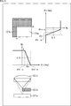
- the waveform of the dotted line in the upper part of FIG. As shown by, the detection signal level of the photodiode 121e-12 changes according to the incident angle ⁇ of the incident light.
- the larger the incident angle ⁇ (the larger the incident angle ⁇ is in the positive direction), the light is focused in the range where the light-shielding film 121b-12 is provided, so that the detection signal level of the photodiode 121e-12 Becomes smaller.
- the smaller the incident angle ⁇ (the larger the incident angle ⁇ is in the negative direction), the light is incident in the range where the light-shielding film 121b-12 is not provided, so that the detection signal level of the photodiode 121e-12 Becomes larger.
- the horizontal axis represents the incident angle ⁇
- the vertical axis represents the detection signal level in the photodiode 121e.
- the waveforms shown by the solid line and the dotted line indicating the detection signal level according to the incident angle ⁇ shown in the upper part of FIG. 8 can be changed according to the range of the light-shielding film 121b. It is possible to have different incident angle directivity.
- the solid line waveform in the upper part of FIG. 8 corresponds to the solid line arrow indicating how the incident light in the middle left part and the lower left part of FIG. 8 is focused by changing the incident angle ⁇ . ..
- the dotted line waveform in the upper part of FIG. 8 corresponds to the dotted arrow indicating how the incident light in the middle right part and the lower right part of FIG. 8 is focused by changing the incident angle ⁇ . ..
- the incident angle directivity referred to here is a characteristic of the detection signal level (light receiving sensitivity characteristic) of each pixel according to the incident angle ⁇ , but in the case of the middle example of FIG. 8, this corresponds to the incident angle ⁇ . It can be said that it is a characteristic of the shading value. That is, the light-shielding film 121b shields the incident light in a specific direction at a high level, but cannot sufficiently block the incident light from a direction other than the specific direction. This change in the light-shielding level causes different detection signal levels depending on the incident angle ⁇ as shown in the upper part of FIG.
- each pixel has different incident angle directivity. It will have a direction.
- two photodiodes 121f-1 and 121f-2 are provided for one on-chip lens 121c-11 (pixel output unit is 2).
- pixel output unit is 2
- the photodiode on the left side of the middle stage of FIG. 8 is used. It is possible to obtain the same detection signal level as in the state where the right side of 121e-11 is shielded from light.
- the incident angle ⁇ which is the angle formed by the incident light
- the incident angle ⁇ increases with respect to the alternate long and short dash line at the center position of the on-chip lens 121c (when the incident angle ⁇ increases in the positive direction).
- the light is focused in the range of the photodiode 121f-1 from which the detection signal is read, so that the detection signal level is increased.
- the smaller the incident angle ⁇ the larger the incident angle ⁇ is in the negative direction
- the detection signal level is because the light is focused in the range of the photodiode 121f-2 where the detected value is not read out.
- two photodiodes 121f-11 and 121f-12 are provided for one on-chip lens 121c-12.
- the incident angle ⁇ which is the angle formed by the incident light
- the incident angle ⁇ increases with respect to the alternate long and short dash line at the center position of the on-chip lens 121c (when the incident angle ⁇ increases in the positive direction).
- the light is focused in the range of the photodiode 121f-11 where the detection signal does not contribute to the detection signal of the output pixel unit, so that the detection signal level of the detection signal of the output pixel unit becomes small.
- the smaller the incident angle ⁇ (the larger the incident angle ⁇ is in the negative direction), the light is focused in the range of the photodiode 121f-12 in which the detection signal contributes to the detection signal of each output pixel. , The detection signal level of the detection signal for each output pixel becomes large.
- the incident angle directivity it is desirable that the randomness is high.
- the above equations (1) to (3) or the equations (4) to (6) described later may be the same equations. This is because the relationship between the unknown number that is the solution of the simultaneous equations and the number of equations cannot be satisfied, and the pixel values constituting the restored image may not be obtained.
- one photodiode 121e-11 and a photodiode 121e-12 are formed in the pixel 121a.
- one pixel output unit when one pixel output unit is composed of a plurality of photodiodes 121f, it can be considered that the output pixel value of the pixel output unit is modulated according to the incident angle. can. Therefore, it is possible to make the characteristics of the output pixel value (incident angle directivity) different for each pixel output, and the incident angle directivity for each pixel output is set. Further, when one pixel output unit is configured from a plurality of photodiodes 121f, one on-chip lens 121c is indispensable for one pixel output unit in order to generate incident angle directivity in one pixel output unit. It becomes a composition.
- the one-pixel output unit is configured according to the incident angle.
- the incident light on one photodiode 121e-11 or the photodiode 121e-12 is modulated, and as a result, the output pixel value is modulated. Therefore, the characteristics of the output pixel value (incident angle directivity) can be made different, and the incident angle directivity is set in units of one pixel output.
- the incident angle directivity is independently manufactured by the light-shielding film 121b provided for each pixel output unit. Sometimes set.
- the number of the plurality of photodiodes 121f for setting the incident angle directivity for each pixel output unit is independently set at the time of manufacture in the 1-pixel output unit, and which photodiode 121f is used to determine the incident angle directivity. Whether to set it can be switched at the time of imaging.
- the setting range of the light-shielding film 121b is the range from the left end to the position A in the horizontal direction of the pixel 121a, and the range from the upper end to the position B in the vertical direction. do.
- the weight Wh is set so that the weight Wx becomes ( ⁇ ( ⁇ x ⁇ a) / 2 ⁇ + 1/2) when ⁇ ⁇ a + ⁇ and the weight Wx becomes 0 when the incident angle ⁇ x> ⁇ a + ⁇ .
- the weight Wh is 0,0.5,1 will be described, but the weight Wh will be 0,0.5,1 when the ideal condition is satisfied.
- the incident angle directivity of each pixel 121a that is, the coefficient (coefficient set) corresponding to the light receiving sensitivity characteristic can be obtained.
- the on-chip lenses 121c having different focal lengths are used for the inclination (1 / 2 ⁇ ) indicating the change in the weight in the range where the weight Wx in the horizontal direction and the weight Wy in the vertical direction are around 0.5. It can be set with.
- the incident angle directivity of the pixel 121a can be set to a different value by making the range in which the photodiode 121e is shielded by the light-shielding film 121b and the curvature of the on-chip lens 121c different.
- the curvature of the on-chip lens may be the same for all the pixels in the image sensor 121, or may be different for some pixels.
- the image sensor 121 does not require an image pickup lens.
- the on-chip lens 121c is necessary at least when the incident angle directivity is realized by using a plurality of photodiodes in the pixel as described with reference to FIG.
- the on-chip lens 121c and the imaging lens have different physical actions.
- the imaging lens has a condensing function for incident light incident from the same direction onto a plurality of pixels adjacent to each other.
- the light passing through the on-chip lens 121c is incident only on the light receiving surface of the photodiode 121e or 121f constituting the corresponding one pixel.
- the on-chip lens 121c is provided for each pixel output unit, and collects the subject light incident on itself only in the corresponding pixel output unit. That is, the on-chip lens 121c does not have a condensing function for incident the diffused light emitted from the virtual point light source on a plurality of pixels adjacent to each other.
- the detection signal levels DA, DB, and DC at the positions Pa, Pb, and Pc on the image sensor 121 can be expressed by the same equations as the above equations (1) to (3).
- DA ⁇ 1 ⁇ a + ⁇ 1 ⁇ b + ⁇ 1 ⁇ c ...
- DB ⁇ 2 ⁇ a + ⁇ 2 ⁇ b + ⁇ 2 ⁇ c ...
- DC ⁇ 3 ⁇ a + ⁇ 3 ⁇ b + ⁇ 3 ⁇ c ...
- the detection signal level is the same for all the detection signal levels DA, DB, and DC as shown in the upper central portion and the lower central portion of FIG. Is.
- the coefficient set group consisting of the coefficient set ⁇ 11, ⁇ 11, ⁇ 11, the coefficient set ⁇ 12, ⁇ 12, ⁇ 12, and the coefficient set ⁇ 13, ⁇ 13, ⁇ 13 is the coefficient set ⁇ 1, ⁇ 1, ⁇ 1, and the coefficient set ⁇ 2 on the subject surface 131, respectively. It is a coefficient set group of the subject surface 131'corresponding to ⁇ 2, ⁇ 2, coefficient set ⁇ 3, ⁇ 3, ⁇ 3.
- the method is the same as the method for obtaining the light intensity (a, b, c) of the light rays in the point light sources PA, PB, and PC in the case of the subject surface 131 shown by.
- one detection image is obtained by storing the coefficient set group for each distance from the image pickup element 121 to the subject surface in advance, switching the coefficient set group to construct simultaneous equations, and solving the constructed simultaneous equations. Based on the above, it is possible to obtain restored images of subject surfaces having various subject distances.
- the detected image is captured only once, and in the subsequent processing, the coefficient set group is switched according to the distance to the subject surface to obtain the restored image, so that the restored image at an arbitrary distance is generated. It is also possible to do.
- deep learning is performed on the detection signal of the image sensor without performing image recognition based on the restored image after obtaining the restored image. It is also possible to apply machine learning such as, and perform image recognition or the like using the detection signal itself.
- the pixels having incident angle directivity suitable for imaging the subject surface corresponding to the specified subject distance and angle of view without using all the pixels.
- the restored image may be generated by using the detected image composed of the detection signal. By doing so, the restored image can be obtained by using the detection signal of the pixel suitable for imaging the subject surface corresponding to the specified subject distance and angle of view, so that the specified subject distance and angle of view can be obtained. It is possible to obtain the restored image with high accuracy.
- the reason why the restored image can be obtained with high accuracy by obtaining the restored image using the detection signal of the pixel suitable for imaging the subject surface corresponding to the specified subject distance and angle of view will be described. ..
- the pixel 121a is shaded by the light-shielding film 121b by the width d1 from each end of each of the four sides, and as shown in the lower part of FIG. 11, each of the four sides.
- Pixels 121a are used, for example, to restore the image I1 of FIG. 11, which corresponds to the angle of view SQ1 including the entire subject person H101, as shown in the upper part of FIG.
- the pixel 121a in FIG. 11 is in the incidentable angle range A of the incident light with respect to the image sensor 121 as shown in the left portion of FIG. 13, so that the subject width is horizontal on the subject surface 131. This is because it can receive the incident light for W1 minutes.
- the pixel 121a'of FIG. 11 has a wider light-shielding range than the pixel 121a of FIG. 11, as shown in the left part of FIG. 13, incident light can be incident on the image sensor 121.
- the angle range B ( ⁇ A) is obtained, so that the incident light corresponding to the subject width W2 ( ⁇ W1) is received in the horizontal direction on the subject surface 131.
- the pixel 121a in FIG. 11 having a narrow light-shielding range is a wide angle-of-view pixel suitable for capturing a wide range on the subject surface 131
- the pixel 121a'in FIG. 11 having a wide light-shielding range is It is a narrow angle-of-view pixel suitable for capturing a narrow range on the subject surface 131.
- the wide angle of view pixel and the narrow angle of view pixel referred to here are expressions for comparing both the pixels 121a and 121a'in FIG. 11, and are not limited to this when comparing pixels with other angles of view.
- FIG. 13 shows the relationship between the position on the subject surface 131 and the incident angle of the incident light from each position with respect to the center position C1 of the image sensor 121. Further, in FIG. 13, the relationship between the position on the subject surface 131 and the incident angle of the incident light from each position on the subject surface 131 with respect to the horizontal direction is shown, but the same relationship is also shown in the vertical direction. It becomes. Further, on the right side of FIG. 13, pixels 121a and 121a'in FIG. 11 are shown.
- the pixel 121a of FIG. 11 is in the range ZA surrounded by the dotted line, and the pixel 121a of FIG. 11 is in the range ZB surrounded by the alternate long and short dash line.
- the pixel 121a of FIG. 11 that captures the angle of view SQ1 is used when trying to restore the image of the angle of view SQ1 corresponding to the subject width W1.
- the image of the subject width W1 of the subject surface 131 can be appropriately restored.
- the detection signal level of the pixel 121a'of FIG. 11 that captures the angle of view SQ2 is used to appropriately obtain the subject width W2. You can restore the image of.
- the angle of view SQ2 is narrower than the angle of view SQ1
- the angle of view SQ2 is narrower than the image of the angle of view SQ1. It is possible to obtain a restored image with higher image quality by restoring the image having the angle of view SQ2 which is the angle of view.
- all the pixels of the wide angle of view pixels may be used, or a part of the wide angle of view pixels may be used.
- all the pixels of the narrow angle of view pixels may be used, or a part of the narrow angle of view pixels may be used.
- an optical element composed of an image sensor, a diffraction grating, etc., a pinhole, and the like are not required, so that the degree of freedom in designing the device can be increased. , It is possible to realize the miniaturization of the device with respect to the incident direction of the incident light, and it is possible to reduce the manufacturing cost. Further, a lens corresponding to an imaging lens for forming an optical image, such as a focus lens, is not required.
- the image sensor 121 only the detected image is acquired, and then the restored image is obtained by solving the simultaneous equations constructed by selectively using the coefficient set group according to the subject distance and the angle of view. Therefore, it is possible to generate restored images with various subject distances and angles of view.
- the image sensor 121 can have incident angle directivity in pixel units, it is possible to realize a larger number of pixels as compared with an optical filter made of a diffraction grating and a conventional image sensor or the like. It is possible to obtain a high-resolution and high-angle resolution image sensor.
- the image sensor 121 does not require an optical filter or the like made of a diffraction grating, the optical filter is not distorted by heat due to a high temperature in the usage environment. Therefore, by using such an image sensor 121, it is possible to realize a device having high environmental resistance.
- the light-shielding film 121b that shields the entire pixel 121a in the vertical direction and shields the pixel 121a with a predetermined width in the horizontal direction is horizontal. It is called a band type light-shielding film 121b.
- the light-shielding film 121b that blocks the entire pixel 121a in the horizontal direction and blocks the pixel 121a at a predetermined height in the vertical direction is referred to as a vertical band type light-shielding film 121b.
- a vertical band type and a horizontal band type light-shielding film 121b may be combined to provide the pixel 121a with an L-shaped light-shielding film 121b.
- the portion shown in black is the light-shielding film 121b. That is, the light-shielding film 121b-21 to the light-shielding film 121b-24 are light-shielding films of the pixels 121a-21 to 121a-24, respectively.
- Each of these pixels has an incident angle directivity as shown in the right part of FIG.
- the graph shown on the right side of FIG. 14 shows the light receiving sensitivity in each pixel.
- the horizontal axis represents the incident angle ⁇ x in the horizontal direction (x direction) of the incident light
- the vertical axis represents the incident angle ⁇ y in the vertical direction (y direction) of the incident light.
- the light receiving sensitivity within the range C4 is higher than outside the range C4
- the light receiving sensitivity within the range C3 is higher than outside the range C3
- the light receiving sensitivity within the range C2 is higher than outside the range C2.
- the light receiving sensitivity within the range C1 is higher than outside the range C1.
- the detection signal level of the incident light that satisfies the conditions of the incident angle ⁇ x in the horizontal direction (x direction) and the incident angle ⁇ y in the vertical direction (y direction) within the range C1 becomes the highest. It is shown that the detection signal level decreases in the order of the conditions in the range C2, the range C3, the range C4, and the range other than the range C4.
- the intensity of such light receiving sensitivity is determined by the range of light shielding by the light shielding film 121b.
- each pixel 121a indicates the color of the color filter (for convenience of explanation, it is not actually described).
- Pixel 121a-21 is a G pixel on which a green color filter is arranged
- pixel 121a-22 is an R pixel on which a red color filter is arranged
- pixel 121a-23 is a B on which a blue color filter is arranged.
- It is a pixel
- the pixels 121a-24 are G pixels in which a green color filter is arranged. That is, these pixels form a Bayer array.
- the color filter array pattern is arbitrary.
- the arrangement of the light-shielding film 121b and the color filter are irrelevant.
- a filter other than the color filter may be provided in some or all of the pixels, or the filter may not be provided.
- the “L-shaped” light-shielding film 121b shields the left side and the lower side of the pixel 121a in the figure
- the “L-shaped” light-shielding film 121b The orientation of is arbitrary and is not limited to the example of FIG.
- the "L-shaped" light-shielding film 121b may shield the lower side and the right side of the pixel 121a in the drawing, or may shield the right side and the upper side of the pixel 121a in the figure.
- the upper side and the left side of the pixel 121a in the drawing may be shielded from light.
- the orientation of the light-shielding film 121b can be set independently for each pixel.
- the "L-shaped" light-shielding film 121b is also collectively referred to as an "L-shaped light-shielding film 121b".
- the description of this example can also be applied to the case where the incident angle directivity is given by selectively using a plurality of photodiodes arranged in the pixel. That is, for example, by appropriately setting the division position (size and shape of each partial region), the position, size, shape, etc. of each photodiode, and appropriately selecting the photodiode, the above-mentioned L It is possible to realize the incident light directivity equivalent to the incident light directivity by the character-type light-shielding film 121b.
- the light-shielding film 121b may be provided so as to have an incident angle directivity.
- the width of the light-shielding film 121b in the horizontal direction changes from the width dx1, dx2, ... dxn with respect to the pixel arrangement in the horizontal direction, and this is dx1 ⁇ dx2 ⁇ ... -The relationship is ⁇ dxn.
- the vertical height of the light-shielding film 121b changes to heights dy1, dy2, ... dym, which is dy1 ⁇ dy2 ⁇ ... ⁇ dxm. Become a relationship.
- the interval between changes in the horizontal width and the vertical width of the light-shielding film 121b depends on the subject resolution (angle resolution) to be restored.
- each pixel 121a in the image sensor 121'in FIG. 15 is such that the light-shielding range is changed so as to correspond to the pixel arrangement in the image sensor 121' in the horizontal direction and the vertical direction. It can be said that it has angular directivity.
- the shading range of each pixel 121a in FIG. 15 is determined according to, for example, the rules described using the pixel 121a shown on the left side of FIG.
- FIG. 16 shows the same configuration of the image sensor 121'as that of FIG. Further, the left portion of FIG. 16 shows the configuration of the pixel 121a of the image pickup device 121'in the right portion of FIG. 16 (same as FIG. 15).
- the light-shielding film 121b shields the pixel 121a from the upper and lower ends of the pixel 121a toward the inside of the pixel 121a by the width dx1, respectively, and from the ends of the left side and the right side into the pixel 121a.
- the light-shielding film 121b shields light by the height dy1 of each. In FIGS. 15 to 17, the light-shielding film 121b is in the range shown in black.
- the range in which the light-shielding film 121b is light-shielded in this way is hereinafter referred to as the main light-shielding portion Z101 of the pixel 121a (black portion in the left portion of FIG. 16), and other than that.
- the range of the square shape is referred to as the range Z102.
- the pixel arrangement in the image sensor 121'in FIG. 15 is at the left end portion, and the pixel 121a-1 at the upper end portion has a rectangular opening Z111.
- the left side thereof has a width dx1 from the left side of the pixel 121a, and the upper side thereof is arranged at a distance of dy1 from the upper side of the pixel 121a.
- the pixel 121a-2 to the right of the pixel 121a-1 has a rectangular opening Z111 whose left side has a width dx2 from the left side of the pixel 121a and whose upper side is a distance of a height dy1 from the upper side of the pixel 121a.
- the area other than the rectangular opening Z111 is shielded by the light-shielding film 121b.
- the right side of the rectangular opening Z111 moves from the right side of the pixel 121a to the width dx1, dx2 ... dxn as the arrangement advances to the right side in the drawing.
- the dotted square portion in the upper right portion of the range Z102 in FIG. 16 is the rectangular opening Z111, the left side thereof is the width dxn from the left side of the pixel 121a, and the upper side thereof is the distance from the upper side of the pixel 121a to the height dy1. It shows the state when it is placed in. Further, each interval of the widths dx1, dx2 ...
- dxn is a value obtained by subtracting the width of the rectangular opening Z111 from the horizontal width of the range Z102 and dividing by the number of pixels n in the horizontal direction. That is, the interval of change in the horizontal direction is determined by dividing by the number of pixels n in the horizontal direction.
- the horizontal position of the rectangular opening Z111 in the pixel 121a in the image pickup element 121' is the same in the pixel 121a (pixels 121a in the same row) having the same horizontal position in the image pickup element 121'. ..
- the pixel 121a-3 adjacent immediately below the pixel 121a-1 has a rectangular opening Z111 whose left side has a width dx1 from the left side of the pixel 121a and whose upper side is a distance of a height dy2 from the upper side of the pixel 121a.
- the area other than the rectangular opening Z111 is shielded by the light-shielding film 121b.
- the upper side of the rectangular opening Z111 moves from the upper side of the pixel 121a to the heights dy1, dy2 ... Dyn as the arrangement advances to the lower side in the drawing. ..
- the dotted square portion at the lower left in the range Z102 of FIG. 16 is the rectangular opening Z111, the left side of which is the width dx1 from the left side of the pixel 121a, and the upper side is the distance of the height dym from the upper side of the pixel 121a. It shows the state when it is placed in. Further, the respective intervals of the heights dy1, dy2 ...
- dym are the value obtained by subtracting the height of the rectangular opening Z111 from the height in the vertical direction of the range Z102 and dividing by the number of pixels m in the vertical direction. Become. That is, the interval of change in the vertical direction is determined by dividing by the number of pixels m in the vertical direction.
- the vertical position of the rectangular opening Z111 in the pixel 121a in the image sensor 121' is the same in the pixel 121a (pixel 121a in the same row) having the same vertical position in the image sensor 121'. ..
- the angle of view can be changed by changing the main light-shielding portion Z101 and the rectangular opening Z111 of each pixel 121a constituting the image sensor 121'shown in FIG. 16 (FIG. 15).
- FIG. 17 shows the configuration of the image sensor 121'when the angle of view is widened with respect to the image sensor 121' of FIG. 16 (FIG. 15).
- the left portion of FIG. 17 shows the configuration of the pixel 121a of the image pickup device 121'in the right portion of FIG.
- a main shading portion Z151 black portion in the left portion of FIG. 17
- the other range is set to the range Z152.
- a rectangular opening Z161 having a larger opening area than the rectangular opening Z111 is set.
- the width dx1'( ⁇ dx1) is shielded by the light-shielding film 121b from the upper and lower ends of the pixel 121a toward the inside of the pixel 121a, respectively, and the left side.
- the rectangular opening Z161 is formed by being shielded by the light-shielding film 121b by the height dy1'( ⁇ dy1) from the end on the right side toward the inside of the pixel 121a.
- the pixel 121a-1 at the left end portion and the upper end portion has a rectangular opening Z161, and the left side thereof has a width dx1'from the left side of the pixel 121a.
- the upper side thereof is arranged at a distance of height dy1'from the upper side of the pixel 121a, and the range other than the rectangular opening Z161 is shielded by the light-shielding film 121b.
- the pixel 121a-2 to the right of the pixel 121a-1 has a rectangular opening Z161 whose left side has a width dx2'from the left side of the pixel 121a and whose upper side has a height dy1'from the upper side of the pixel 121a.
- the area other than the rectangular opening Z161 is shielded by the light-shielding film 121b.
- the right side of the rectangular opening Z161 moves from the right side of the pixel 121a to the width dx1', dx2'... dxn' as the arrangement advances to the right side in the drawing. do.
- the respective intervals of the widths dx1', dx2'... dxn' are the width obtained by subtracting the horizontal width of the rectangular opening Z161 from the horizontal width of the range Z152, and the number of pixels in the horizontal direction n. It becomes the divided value. That is, the interval of change in the vertical direction is determined by dividing by the number of pixels n in the horizontal direction. Therefore, the interval of change of the width dx1', dx2'... dxn'is larger than the interval of change of the width dx1, dx2 ... dxn.
- the horizontal position of the rectangular opening Z161 in the pixel 121a in the image sensor 121'in FIG. 17 is in the pixel 121a (pixels 121a in the same row) having the same horizontal position in the image sensor 121'. Be the same.
- the pixel 121a-3 immediately below the pixel 121a-1 has a rectangular opening Z161 whose left side has a width dx1'from the left side of the pixel 121a and its upper side has a height dy2'from the upper side of the pixel 121a.
- the area other than the rectangular opening Z161 is shielded by the light-shielding film 121b.
- the upper side of the rectangular opening Z161 has a height dy1', dy2' ... dym'from the upper side of the pixel 121a as the arrangement advances to the lower side in the drawing. It changes with.
- the interval of change of the heights dy1', dy2'... dym' is the height obtained by subtracting the height of the rectangular opening Z161 from the height in the vertical direction of the range Z152 with the number of pixels in the vertical direction m. It becomes the divided value. That is, the interval of change in the vertical direction is determined by dividing by the number of pixels m in the vertical direction. Therefore, the interval of change of height dy1', dy2'... dym'is larger than the interval of change of width height dy1, dy2 ... dym.
- the vertical position of the rectangular opening Z161 in the pixel 121a in the image sensor 121'in FIG. 17 is in the pixel 121a (pixel 121a in the same row) having the same vertical position in the image sensor 121'. Be the same.
- the image sensor 121'consisting of pixels 121a having various angles of view (having various incident angle directivities) can be obtained. It will be possible to realize.
- pixels 121a having the same angle of view may be combined to realize the image sensor 121.
- each unit U has wide angle of view pixels 121a-W and medium angle of view. It is composed of four pixels: pixels 121a-M, pixels 121a-N having a narrow angle of view, and pixels 121a-AN having an extremely narrow angle of view.
- the number of pixels of all the pixels 121a is X
- four different coefficient sets are used for each angle of view, and restored images having different angles of view are restored by four different simultaneous equations.
- the image of the angle of view in the middle of the four types of angles of view and the images of the angles of view before and after the angle of view may be interpolated and generated from the images of the four types of angles of view, and the images of various angles of view are seamlessly generated. By doing so, a pseudo optical zoom may be realized.
- the description of this example can also be applied to the case where the incident angle directivity is given by selectively using a plurality of photodiodes arranged in the pixel. That is, for example, by appropriately setting the division position (size and shape of each partial region), the position, size, shape, etc. of each photodiode, and appropriately selecting the photodiode, the above-mentioned rectangle It is possible to realize the incident light directivity equivalent to the incident light directivity by the light-shielding film 121b having an opening. Of course, also in this case, the image sensor 121 can be realized by combining the pixels 121a having various angles of view.
- images with an intermediate angle of view and images with angles of view before and after the angle of view may be interpolated and generated from images with a plurality of types of angles of view.
- pseudo Optical zoom may be realized.
- ⁇ Third modification example> By the way, when the light-shielding range of the light-shielding film 121b of the pixel 121a in the image sensor 121 is given randomness, the greater the disorder of the difference in the light-shielding range of the light-shielding film 121b, the greater the disorder of the restoration unit 321 and the like.
- the processing load is large. Therefore, the processing load may be reduced by reducing the disorder by making a part of the change in the light-shielding range of the light-shielding film 121b of the pixel 121a regular.
- an L-shaped light-shielding film 121b that combines a vertical band type and a horizontal band type is formed, and a horizontal band type light-shielding film 121b having the same width is combined in a predetermined row direction.
- the light-shielding film 121b is made to change randomly in pixel units while having regularity in the column direction and the row direction. As a result, the randomness in the incident angle directivity of each pixel may be reduced, and the external processing load of the image pickup element 121 such as the restoration unit 321 may be reduced.
- a horizontal band type light-shielding film 121b having the same width X0 is used, and the range Z150.
- a vertical band type light-shielding film 121b having the same height Y0 is used, and for the pixels 121a specified in each matrix, an L-shaped light-shielding film 121b in which these are combined is used. Is set.
- a horizontal band type light-shielding film 121b having the same width X1 is used, and the same row indicated by the range Z151 adjacent to the range Z150.
- a vertical band type light-shielding film 121b having the same height Y1 is used, and for the pixels 121a specified in each matrix, an L-shaped light-shielding film 121b in which these are combined is set. ..
- a horizontal band type light-shielding film having the same width X2 is used, and the pixels in the same row indicated by the range Z152 adjacent to the range Z151 are used.
- a vertical band type light-shielding film having the same height Y2 is used, and an L-shaped light-shielding film 121b in which these are combined is set for the pixels 121a specified in each matrix.
- the range of the light-shielding film can be changed on a pixel-by-pixel basis while giving regularity to the width and position of the light-shielding film 121b in the horizontal direction and the height and position in the vertical direction. It is possible to suppress the disorder of the incident angle directivity, and as a result, it is possible to reduce the pattern of the coefficient set, and it is possible to reduce the processing load of the arithmetic processing in the subsequent stage (for example, the restoration unit 321 etc.). Become.
- each pixel of the restored image of N ⁇ N rows and 1 column is obtained.
- each element of the first column shown by the range Z201 of the matrix A corresponds to the element of the first row of the vector X
- the N ⁇ N column shown by the range Z202 of the matrix A It is shown that each element of is corresponding to the element of the N ⁇ Nth line of the vector X.
- each element of the vector X is obtained, so that the restored image is obtained.
- a pinhole is used, and when a condensing function such as an imaging lens for incident light incident from the same direction is incident on both adjacent pixel output units, the position of each pixel and the position of each pixel are used. Since the relationship between the incident angles of light is uniquely determined, the matrix A is a square matrix in which all diagonal components ((i, i) elements) are 1 and all other than diagonal components are 0. become.
- the relationship between the position of each pixel and the incident angle of light is not uniquely determined, so that the matrix A does not become a diagonal matrix. ..
- the determinant of FIG. 20 is transformed as shown in FIG. 21 by multiplying both sides by the inverse matrix A -1 of the matrix A from the left, and the vector Y of the detected image is transformed by the inverse matrix A ⁇ .
- the vector Y of the detected image is transformed by the inverse matrix A ⁇ .
- the actual matrix A cannot be obtained accurately, cannot be measured accurately, cannot be solved in the case where the basis vector of the matrix A is close to linear dependence, and each element of the detected image contains noise. Or, in combination, it may not be possible to solve simultaneous equations.
- the result of multiplying from the first stage and the second stage of is a matrix Y of N rows and N columns representing the detected image.
- AT is a transposed matrix of the matrix A
- ⁇ is a parameter
- I is an identity matrix
- matrix matrix AL in parenthesis in Equation (8) the inverse matrix of the transposed matrix of the matrix A by the matrix AR T. The determinant shown in FIG. 22 is realized.
- the calculation as shown in FIG. 22 is performed by multiplying the attention element Xp in the matrix X by each element group Z221 of the corresponding column of the matrix AL. Group Z222 is required. Further, by multiplying the elements in the row corresponding to the element of interest Xp the element group Z222 matrix AR T, 2-dimensional response Z224 that corresponds to the element of interest Xp is calculated. Then, the matrix Y is obtained by integrating the two-dimensional response Z224 corresponding to all the elements of the matrix X.
- the incident angle directivity of the horizontal band type pixel 121a set to the same width for each column of the image pickup element 121 shown in FIG. Have a corresponding set of coefficients.
- each row of the element group of the matrix AR T Z223 ( Figure 23), the incidence of vertical band type pixel 121a to be set at the same height to be set for each row of the image sensor 121 shown in FIG. 19 Have a set of coefficients corresponding to the angular directivity.
- the light-shielding range (light-receiving range) is changed on a pixel-by-pixel basis while having predetermined regularity in the horizontal direction and the vertical direction.
- the range in which light is blocked in pixel units (the range in which light can be received) is not completely randomly set, but even if it is set to some extent at random, it is set at random. I reckon.
- the light-shielding range (light-receiving range) is set completely randomly for each pixel, but also for some random ones (for example, some of all pixels).
- the description of this example can also be applied to the case where the incident angle directivity is given by selectively using a plurality of photodiodes arranged in the pixel. That is, for example, by appropriately setting the division position (size and shape of each partial region), the position, size, shape, etc. of each photodiode, and appropriately selecting the photodiode, the above-mentioned pixels It is possible to realize the incident light directivity equivalent to the incident light directivity when a part of the change in the light-shielding range of the light-shielding film 121b of 121a is made regular. By doing so, it is possible to reduce the disorder in the incident angle directivity of each pixel and reduce the external processing load of the image sensor 121 such as the restoration unit 122.
- the variation in the shape of the light-shielding film 121b for each pixel is arbitrary and is not limited to the above-mentioned examples.
- the light-shielding film 121b may be set to be triangular and its range may be different so as to have different incident angle directivity, or the light-shielding film 12b may be set to be circular and its range may be different. By doing so, different incident angle directivities may be provided.
- a linear light-shielding film in an oblique direction may be used.
- the variation (pattern) of the light-shielding film 121b may be set for each of a plurality of pixels constituting the unit composed of a predetermined number of a plurality of pixels.
- This one unit may be composed of any pixel.
- the image sensor 121 may be provided with a color filter, and may be composed of pixels constituting the unit of the color array of the color filter.
- a pixel group in which pixels having different exposure times are combined may be used as a unit. It is desirable that the pattern of the light-shielding film 121b in each pixel constituting the unit has a high degree of randomness, that is, the pixels constituting the unit have different incident angle directivity.
- the arrangement pattern of the light-shielding film 121b may be set between the units. For example, the width and position of the light-shielding film may be changed for each unit. Further, a pattern in a range in which the light-shielding film 121b blocks light may be set in or between units of a plurality of pixels classified in different categories.
- the description of this example can also be applied to the case where the incident angle directivity is given by selectively using a plurality of photodiodes arranged in the pixel. That is, for example, by appropriately setting the division position (size and shape of each partial region), the position, size, shape, etc. of each photodiode, and appropriately selecting the photodiode, the above-mentioned pixels It is possible to realize the incident light directivity equivalent to the incident light directivity when a part of the change in the light-shielding range of the light-shielding film 121b of 121a is made regular. By doing so, it is possible to reduce the disorder in the incident angle directivity of each pixel and reduce the external processing load of the image sensor 121 such as the restoration unit 122.
- the description of this example can also be applied to the case where the incident angle directivity is given by selectively using a plurality of photodiodes arranged in the pixel. That is, by appropriately setting the division position (size and shape of each partial region), the position, size, shape, etc. of each photodiode, and appropriately selecting the photodiode, for example, a triangle or a circle. It is possible to realize the incident light directivity equivalent to the incident light directivity by a light-shielding film having an arbitrary shape such as a linear shape in an oblique direction.
- the setting of the division position (size and shape of each partial region), the setting of the position, size, shape, etc. of each photodiode, the selection of the photodiode, and the like are performed in the same manner as in the case of the light-shielding film 121b described above. , It may be set for each unit.
- ⁇ Photodiode control> When a plurality of photodiodes arranged in the pixels as described above are selectively used with reference to FIG. 6, the presence / absence or degree of contribution to the output pixel value of each pixel output unit of the plurality of photodiodes 121f is switched. Thereby, the incident angle directivity of the output pixel value in the pixel output unit may be changed in various ways.
- the pixels 121a may be used as the pixels 121ab having the photodiodes 121f-111 to 121f-119, or the photodiodes 121f-111, 121f-112, 121f-114, and 121f-115. It may be used as the pixel 121a-s having.
- the incident angle directivity of the output pixel value is controlled by controlling the presence / absence and degree of contribution of the photodiodes 121f-111 to 121f-119 to the output pixel value of the pixel 121a. Is controlled.
- the pixel 121a is the pixel 121a-s
- the presence / absence and degree of contribution of the photodiodes 121f-111, 121f-112, 121f-114, and 121f-115 to the output pixel value of the pixel 121a are determined.
- the incident angle directivity of the output pixel value is controlled.
- the other photodiodes 121f photodiodes 121f-113, 121f-116, 121f-117 to 121f-119 are controlled so as not to contribute to the output pixel value.
- the incident angle directivity of the output pixel values is different between the plurality of pixels 121ab
- the presence or absence of contribution to the output pixel value of at least one of the photodiodes 121f-111 to 121f-119 is determined.
- the degree is different.
- the incident angle directivity of the output pixel value is different between the plurality of pixels 121a-s, at least one of the photodiodes 121f-111, 121f-112, 121f-114, and 121f-115.
- the presence or absence or degree of contribution to one output pixel value is different, and the other photodiodes 121f-113, 121f-116, 121f-117 to 121f-119 are commonly used among these pixels to obtain the output pixel value. Does not contribute.
- Whether the pixel 121a is the pixel 121ab or the pixel 121a-s can be set for each pixel. Further, this setting may be made for each unit (plurality of pixels).
- one on-chip lens is formed in each pixel (each pixel output unit) of the image sensor 121. That is, in the case where the pixel 121a has a configuration as shown in FIG. 24, as shown in FIG. 25, one on-chip lens 121c is provided for the photodiodes 121f-111 to 121f-119. Therefore, as described with reference to FIG. 24, whether the pixel 121a is the pixel 121a-b or the pixel 121a-s, one pixel (one pixel output unit) and one on-chip lens 121c are used. There is a one-to-one correspondence.
- the image sensor 121 has been described above.
- the image pickup unit 101 of FIG. 2 has the above-mentioned image pickup element 121.
- the identification of the restored area (or non-restored area) by the area specifying unit 102 will be described.
- the restored image 301 shown in A of FIG. 26 it is assumed that the person 302-1, the person 302-2, and the person 302-3 are reflected.
- the person 302. When it is not necessary to distinguish the person 302-1 to the person 302-3 from each other, it is referred to as the person 302.
- the predetermined area including the face portion of each person 302 may not be restored.
- the partial area 303-3 including the face portion of the person 302-3 may not be restored.
- the non-restored region 305-1 and the partial region 303-2 having the same position, shape, and size as the partial region 303-1 with respect to the detected image 304.
- a non-restored area 305-2 and a partial area 303-3 having the same position, shape, and size are set as a non-restored area 305-3 having the same position, shape, and size.
- the non-restored area 305-1 to the non-restored area 305-3 are referred to as a non-restored area 305.
- Areas other than the non-restored area of the detected image are set as the restored area. That is, the restored area 306 indicates an area other than the non-restored area 305 of the detected image 304.
- the above-mentioned non-restored area 305 may be used as the restored area
- the above-mentioned restored area 306 may be used as the non-restored area.
- the restored area and the non-restored area can be arbitrarily set in the detected image, but the detected image is actually a subject, for example, as in the detected image 307 shown in FIG. 26D.
- the image is not formed and the user cannot visually recognize the subject. Therefore, in the detected image 307, for example, it is basically impossible for the user to visually identify the face portion as described above and set the non-restored region (or restored region).
- the restored area is specified using AI (Artificial Intelligence).
- AI Artificial Intelligence
- machine learning for example, deep learning
- the non-restored region 305 which may be the restored region 306 corresponding to the detected image as teacher data.
- the non-restored area 305 (restored area 306) used as the teacher data for example, the one specified by the user or the like from the restored image 301 is used.
- Such machine learning is performed using a large amount of teacher data to learn and model features.
- the area specifying unit 102 identifies the restored area (non-restored area) from the detected image by using the learning result (learning data).
- the region to be the restored region may be specified as an region having a predetermined feature.
- a restore area or non-restoration area
- only an arbitrary partial area having that characteristic can be restored, or another area can be restored so as not to restore that partial area.
- Its features are optional. That is, it is possible to restore only an arbitrary partial area having an arbitrary feature, or to restore another area so as not to restore the partial area.
- the partial area of the detected image corresponding to the area including the subject registered in advance in the restored image or the area other than that may be used as the restored area (or non-restored area).
- the restored area or non-restored area
- an area including a person may be used as a restored area (or a non-restored area), or an area other than the area containing the person may be used as a restored area (or a non-restored area).
- an animal such as a dog or a cat may be the target subject, or an object such as a vehicle or a tool may be the target subject.
- the partial area of the detected image corresponding to the area including the pre-registered part of the subject in the restored image or the area other than that may be used as the restored area (or non-restored area). By doing so, it is possible to restore only the area including the pre-registered portion of the pre-registered subject, or to restore another area so as not to restore the area.
- the area including the face part of the person may be set as the restored area (or non-restored area), or the area other than the area including the face part may be set as the restored area (or non-restored area).
- the area other than the area including the face part may be set as the restored area (or non-restored area).
- parts other than the face such as the hands, feet, and upper body, may be the target parts.
- any part of the subject other than the person such as the license plate of the vehicle, the arm part of the machine, and the sign part of the road sign, may be the target part.
- the partial area of the detected image corresponding to the area including the person registered in advance in the restored image or the area other than that may be used as the restored area (or non-restored area).
- the restored area or non-restored area.
- an area including a specific individual may be designated as a restored area (or non-restored area), or an area other than the area including the individual may be designated as a restored area (or non-restored area).
- the area including the pre-registered part (face, etc.) of the individual may be regarded as the restored area (or non-restored area), or the area other than the area including the pre-registered part may be designated as the restored area (or non-restored area). You may.
- the partial area of the detected image corresponding to the area including the subject satisfying the pre-registered conditions in the restored image or the area other than that may be used as the restored area (or non-restored area).
- the restored area or non-restored area
- the area other than the area including the person performing the pre-registered operation is designated as the restored area (or non-restored area). You may.
- the operation under this condition is optional. For example, it may be running, walking, jumping, climbing over a wall, sitting, crouching, driving, etc., or it may be another action. Further, for example, a subject that moves from left to right within the angle of view, a subject that moves from top to bottom, a subject that moves from the back to the front, and the like can be used as subjects that satisfy pre-registered conditions. good.
- the movement (including movement) of the subject may be relative to the absolute coordinate system in the three-dimensional space. For example, the position or posture of the subject may be changed with respect to the periphery (background or the like) of the subject, or the position or posture of the subject may be changed with respect to the image pickup device 100 (image sensor 121). You may.
- this condition is optional and may be other than operation.
- the number of people may be a condition, or the gender, age, height, weight, etc. of an estimated person may be a condition.
- the subject may be other than a person.
- the conditions may be set according to the subject, or may be set for each subject.
- a partial area of a pre-registered position and size of the detected image may be used as a restored area (or a non-restored area). That is, an arbitrary partial area may be used as a restored area (or a non-restored area) regardless of the content (subject) of the image. For example, a partial region having an arbitrary position, size, and shape of the detected image, such as the right half, the left half, the peripheral portion, and the central portion of the detected image, may be used as the restored region (or non-restored region).
- the restored image is restored from the detected image by a matrix operation using a restored matrix (matrix A (or matrix A- 1)) as described with reference to FIGS. 20 and 21. That is, the restored image in the restored area is restored by the matrix calculation of the coefficient corresponding to the restored area of the restored matrix and the pixel value corresponding to the restored area of the detected image. That is, by deriving the matrix operation result only for the restoration area, only the restoration image of the restoration area can be restored.
- matrix A or matrix A- 1
- the restored image can be restored so as not to restore the non-restored area by not deriving the matrix operation result corresponding to the non-restored area.
- the coefficient corresponding to the non-restoration region of the restoration matrix may be set to a predetermined value (for example, "0").
- the coefficient of the restoration matrix (“Transfer Matrix (coefficient of simultaneous linear equations)” in FIG. 27) corresponding to the shaded portion of the restored image (“SceneImage (what you want to calculate)” in FIG. 27) is the shaded portion.
- the value of the coefficient of the shaded portion of the restored matrix is set to "0". By doing so, even if the restored image is restored from the detected image by performing the matrix operation as shown in FIG. 21, the pixel value of the shaded portion of the restored image becomes "0" (that is, it is not restored). ..
- the restoration matrix update unit 104 generates (sets) a non-restoration area corresponding restoration matrix in which the coefficient corresponding to the non-restoration area is “0” based on the restoration area information. That is, the restoration matrix update unit 104 sets the coefficient not corresponding to the restoration region to a pre-registered value (for example, "0") among the coefficients of the total restoration matrix which is the restoration matrix corresponding to the entire detected image. , A partial restoration matrix used to restore only the restoration image of the restoration area may be generated (set).
- the restoration unit 105 restores the restored image from the detected image by using the restoration matrix corresponding to the non-restoration area (partial restoration matrix), the restoration image in which the pixel value of the non-restoration area is "0" is obtained. That is, the restoration unit 105 can restore the restored image by using the restoration matrix corresponding to the non-restoration area so that the non-restoration area is not restored.
- the "pre-registered value" of the coefficient of the restoration matrix set by the restoration matrix update unit 104 is arbitrary and may be other than "0". That is, this "pre-registered value” may be a value that does not make the subject visible by matrix calculation. For example, this "pre-registered value” may or may not be unified in all the coefficients corresponding to the non-restored area. For example, as this "pre-registered value", a different value may be set for each coefficient or each block.
- the coefficient corresponding to the non-restored region of the restored matrix may be deleted.
- the coefficient corresponding to the non-restored region (shaded portion in FIG. 27) is deleted.
- a restoration matrix consisting of coefficients corresponding to the non-restoration region (that is, a restoration matrix corresponding to the restoration region) is generated.
- this restoration matrix only the restored image in the restored area can be restored from the detected image.
- the restoration matrix update unit 104 generates a non-restoration area correspondence restoration matrix in which the coefficient corresponding to the non-restoration area is deleted, that is, the coefficient corresponding only to the restoration area is deleted based on the restoration area information. (Set). That is, the restoration matrix update unit 104 restores only the restored image in the restoration area by deleting the coefficient that does not correspond to the restoration area among the coefficients of the total restoration matrix that is the restoration matrix corresponding to the entire detection image. You may generate (set) a partial restoration matrix used for.
- the restoration unit 105 restores the restored image from the detected image by using the restoration matrix corresponding to the non-restoration area (partial restoration matrix), the restoration image in which the pixel value of the non-restoration area is "0" is obtained. That is, the restoration unit 105 can restore the restored image by using the restoration matrix corresponding to the non-restoration area so that the non-restoration area is not restored.
- the restoration matrix corresponding to the non-restoration area does not correspond to the entire detected image. That is, as described above, the non-restored region-corresponding restore matrix does not include the coefficient corresponding to the non-restored region. Therefore, information (for example, information indicating a restored region (or non-restored region) in the detected image) that associates each coefficient of the restored matrix corresponding to the non-restored region with the pixels of the detected image is required. Based on the information, the restoration unit 105 can correctly associate the restoration region in the detected image with the restoration matrix corresponding to the non-restoration region. This information may be known to the restoration unit 105 in advance, or may be supplied from the restoration matrix update unit 104 to the restoration unit 105 together with the restoration matrix corresponding to the non-restoration area.
- the image pickup unit 101 of the image pickup device 100 takes an image of the subject using the image pickup element 121 in step S301 and generates a detection image.
- step S302 the area specifying unit 102 identifies a restored area (or non-restored area) from the detection image generated in step S301 based on the learning data read from the learning data storage unit 103, and indicates the restored area. Generates restored area information (or non-restored area information indicating a non-restored area).
- step S303 the restoration matrix update unit 104 updates the restoration matrix corresponding to the entire detected image based on the restoration area information (or non-restoration area information) generated in step S302, and creates the restoration matrix corresponding to the non-restoration area. Generate.
- step S304 the restoration unit 105 restores the restored image from the detected image generated in step S301 by using the restoration matrix corresponding to the non-restoration area generated in step S303 so as not to restore the non-restoration area.
- step S305 the restoration unit 105 outputs a restored image in which only the restoration area is restored in step S304. Even if the process of step S304 is omitted and the restoration unit 105 outputs the detection image generated in step S301 and the restoration matrix corresponding to the non-restoration region generated in step S303 in step S305 in association with each other. good.
- step S305 When the process of step S305 is completed, the restored image generation process is completed.
- the area specifying unit 102 can control the area to be restored by specifying the restored area (non-restored area). Therefore, by executing each process as described above, the image pickup apparatus 100 can restore the restored image so as not to restore an arbitrary area.
- Image processing system example 1> In the above, the present technology has been described by taking an imaging device as an example, but the present technology is not limited to this example, and the present technology is not limited to this example, for example, an image processing device, an image coding device, an image decoding device, an information processing device, a communication device, an electronic device, and the like. Alternatively, it can be applied to any configuration such as a system composed of a plurality of devices.
- FIG. 30 is a diagram showing a main configuration example of an embodiment of an image processing system to which the present technology is applied.
- the image processing system 400 shown in FIG. 30 is a system having the same function as the image pickup apparatus 100, and is a system that captures a subject and restores a restored image from the obtained detected image. That is, the image processing system 400 has ⁇ 1.
- the restored image non-restored area
- the restored image can be set for the detected image, and the restored image can be restored so as not to restore the non-restored area.
- the image processing system 400 includes an image pickup device 401 and an image processing device 402.
- the image pickup apparatus 401 can capture a subject, generate a detection image, and output the detection image and a restoration matrix corresponding to the detection image.
- the image processing device 402 acquires a detected image supplied from the outside and a restoration matrix corresponding to the detected image, sets a restoration area (or a non-restoration area) for the detected image, and indicates restoration area information indicating the restoration area. (Or non-restored area information indicating the non-restored area) can be generated. Further, the image processing device 402 updates the acquired restoration matrix based on the restoration area information, and restores only the restoration area (or restores the non-restoration area so as not to restore it). A region-aware restoration matrix can be generated. Further, the image processing device 402 uses the restoration matrix corresponding to the non-restoration area to obtain a restored image (or a restored image restored so as not to restore the non-restoring area) from the acquired detection image. Can be generated and output.
- the image processing device 402 controls, for example, disclosure / non-disclosure of an arbitrary area of the detected image, control of information protection / non-protection against unauthorized leakage or unauthorized use, and image analysis. It is possible to control the target range of the above and the level of the service to be provided. Further, in the transmission of the image from the image pickup device 401 to the image processing device 402, the detected image is transmitted, so that the information can be protected and the occurrence of infringement of the privacy right due to unauthorized leakage or unauthorized use of the image can be suppressed. can do.
- the imaging device 401 has an imaging unit 101.
- the image processing device 402 has an area specifying unit 102 to a restoring unit 105.
- Each processing unit performs the same processing as in the case of the image pickup apparatus 100. That is, each processing unit of the image pickup apparatus 401 and the image processing apparatus 402 performs processing according to the flow chart shown in FIG. 31, for example.
- step S401 the image pickup unit 101 of the image pickup device 401 uses the image pickup device 121 to image the subject and generate a detection image.
- step S402 the image pickup apparatus 401 supplies the detected image and the restoration matrix (total restoration matrix) corresponding to the detected image to the image processing apparatus 402.
- step S411 the image processing apparatus 402 acquires the supplied detection image and the restoration matrix.
- the detected image and the restoration matrix may be supplied from the image pickup apparatus 401 to the image processing apparatus 402 by communication via an arbitrary communication medium.
- This communication method is arbitrary, and may be wired communication, wireless communication, or both. Further, this communication may be performed via a single network such as the Internet or a LAN (Local Area Network) or a plurality of networks, or may be performed via another device such as a communication device or a relay device. .. Further, this communication may be performed via a server or so-called cloud computing.
- information may be exchanged via an arbitrary storage medium such as a removable flash memory or a hard disk. That is, the information to be exchanged may be stored in an arbitrary storage medium connected to the device of the supply source, the storage medium may be connected to the device of the supply destination, and the information may be read from the storage medium.
- an arbitrary storage medium such as a removable flash memory or a hard disk.
- step S412 the area specifying unit 102 of the image processing device 402 identifies the restored area (or non-restored area) from the detected image acquired in step S411 based on the learning data read from the learning data storage unit 103. Generates restored area information (or non-restored area information indicating a non-restored area) indicating the restored area.
- step S413 the restoration matrix update unit 104 updates the restoration matrix acquired in step S411 based on the restoration area information (or non-restoration area information), and generates a restoration matrix corresponding to the non-restoration area.
- step S414 the restoration unit 105 restores only the restoration area from the detected image acquired in step S411 using the restoration area-corresponding restoration matrix generated in step S413 (in other words, non-restoration). Restore (generate) the restored image (so as not to restore the area).
- step S415 the image processing device 402 uses the image processing device for the restored image (in other words, the restored image restored so as not to restore the non-restored area) generated in step S414 in which only the restored area is restored. Output to the outside of 402.
- the restored image in other words, the restored image restored so as not to restore the non-restored area
- the output to the outside may be performed by communication via an arbitrary communication path, or may be performed via an arbitrary storage medium (that is, information is stored in the storage medium and output). You may.
- the image processing system 400 can control the area to be restored. Therefore, the image processing system 400 controls the disclosure / non-disclosure of an arbitrary area of the detected image, controls the protection / non-protection of information against unauthorized leakage or unauthorized use, and covers the target range such as image analysis. You can control and control the level of service provided. Further, in the transmission of the image from the image pickup device 401 to the image processing device 402, the detected image is transmitted, so that the information can be protected and the occurrence of infringement of the privacy right due to unauthorized leakage or unauthorized use of the image can be suppressed. can do.
- step S414 may be omitted, and in step S415, the image processing device 402 may associate the detected image with the restoration matrix corresponding to the non-restoration area and output it to the outside. That is, the restored image may be restored outside the image processing device 402, and in that case, the restoration unit 105 associates the detected image with the restoration matrix corresponding to the non-restoration area without performing this restoration, and the image. Output to a restoration device that performs restoration processing outside the processing device 402. By doing so, the image processing device 402 can transmit the image to the restoration device (another device) in a state where the information is protected. Therefore, it is possible to suppress the occurrence of infringement of privacy rights due to unauthorized leakage or unauthorized use of images.
- the restoration unit 105 may be provided in the image pickup apparatus 401.
- the restoration matrix update unit 104 supplies the derived restoration matrix corresponding to the non-restoration region to the restoration unit 105 of the imaging device 401. That is, the restoration matrix corresponding to the non-restoration region is transmitted from the image processing device 402 to the image pickup device 401.
- the restoration unit 105 of the image pickup apparatus 401 uses the restoration matrix corresponding to the non-restoration region supplied from the restoration matrix update unit 104 of the image processing apparatus 402, and only the restoration region is obtained from the detected image supplied from the imaging unit 101. Restore (generate) the restored image so that it restores (in other words, does not restore the non-restored area).
- the restoration matrix update unit 104 may also be provided in the image pickup apparatus 401.
- the area identification unit 102 supplies the restoration area information to the restoration matrix update unit 104 of the imaging device 401. That is, the restoration area information is transmitted from the image processing device 402 to the image pickup device 401.
- the restoration matrix updating unit 104 of the image pickup apparatus 401 updates the restoration matrix supplied from the imaging unit 101 based on the restoration region information supplied from the region identification unit 102 of the image processing apparatus 402, and the non-restoration region. Generate a corresponding restore matrix.
- the restoration unit 105 of the image pickup apparatus 401 uses the restoration matrix corresponding to the non-restoration region to restore only the restoration region from the detected image supplied from the imaging unit 101 (in other words, the non-restoration region is not restored). To restore (generate) the restored image.
- the image processing system 400 can protect the information, and the image processing system 400 can protect the information, such as illegal leakage or unauthorized use of the image. It is possible to suppress the occurrence of infringement of privacy rights due to.
- FIG. 32 is a diagram showing a main configuration example of another embodiment of an image processing system to which the present technology is applied. Similar to the image processing system 400 (FIG. 30), the image processing system 410 shown in FIG. 32 is a system that captures an image of a subject and restores a restored image from the obtained detected image, and has a restored area (restored area) with respect to the detected image. You can set the non-restored area) and restore the restored image so that the non-restored area is not restored.
- the image processing system 410 includes an image pickup device 411, an image processing device 412, and a restoration device 413. Similar to the image pickup device 401, the image pickup apparatus 411 can image a subject, generate a detection image, and output the detection image and the restoration matrix corresponding to the detection image.
- the image processing device 412 acquires a detected image supplied from the outside and a restoration matrix corresponding to the detected image, sets a restoration area (or a non-restoration area) for the detected image, and indicates restoration area information indicating the restoration area. (Or non-restored area information indicating the non-restored area) can be generated. Further, the image processing device 412 updates the acquired restoration matrix based on the restoration area information, and restores only the restoration area (or restores the non-restoration area so as not to restore it). A restore matrix corresponding to the restore area can be generated and output.
- the restoration device 413 acquires the restoration matrix corresponding to the non-restoration region and the detected image supplied from the outside, and uses the restoration matrix corresponding to the non-restoration region to restore only the restoration region from the detected image (or non-restoration image). It is possible to generate and output a restored image) that has been restored so that the restored area is not restored.
- the imaging device 411 has an imaging unit 101.
- the image processing device 412 has an area specifying unit 102 to a restoration matrix updating unit 104.
- the restoration device 413 has a restoration unit 105.
- Each processing unit performs the same processing as in the case of the image pickup apparatus 100. That is, each processing unit of the image pickup apparatus 411, the image processing apparatus 412, and the restoration apparatus 413 performs processing according to the flow chart shown in FIG. 33, for example.
- step S421 the image pickup unit 101 of the image pickup device 411 images the subject using the image pickup device 121 and generates a detection image.
- step S422 the image pickup apparatus 411 supplies the detected image and the restoration matrix (total restoration matrix) corresponding to the detected image to the image processing apparatus 412.
- step S431 the image processing apparatus 412 acquires the supplied detection image and the restoration matrix.
- step S423 the image pickup device 411 supplies the detected image to the restoration device 413.
- step S441 the restoration device 413 acquires the supplied detection image. Information can be exchanged between the devices by any method as in the case of the image processing system 400.
- step S432 the area specifying unit 102 of the image processing device 412 identifies the restored area (or non-restored area) from the detected image acquired in step S431 based on the learning data read from the learning data storage unit 103. Generates restored area information (or non-restored area information indicating a non-restored area) indicating the restored area.
- step S433 the restoration matrix update unit 104 updates the restoration matrix acquired in step S431 based on the restoration area information (or non-restoration area information), and generates a restoration matrix corresponding to the non-restoration area.
- step S434 the image processing device 412 supplies the restoration matrix corresponding to the non-restoration area to the restoration device 413.
- step S442 the restoration device 413 acquires the supplied non-restoration region corresponding restoration matrix.
- step S443 the restoration unit 105 of the restoration device 413 restores only the restoration area from the detection image acquired in step S441 by using the restoration matrix corresponding to the non-restoration area acquired in step S442 (in other words). To restore (generate) the restored image (so as not to restore the non-restored area).
- step S444 the restoration device 413 transfers the restoration image (in other words, the restoration image restored so as not to restore the non-restoration area) generated in step S443, in which only the restoration area is restored, to the restoration device 413. Output to the outside.
- the restoration image in other words, the restoration image restored so as not to restore the non-restoration area
- the output to the outside may be performed by communication via an arbitrary communication path, or may be performed via an arbitrary storage medium (that is, information is stored in the storage medium and output). You may.
- the restoration device 413 can output the image in a state where the information is protected for the desired area of the image. As a result, it is possible to suppress the occurrence of infringement of privacy rights due to unauthorized leakage or unauthorized use of images. Further, by executing each process in this way, the image processing system 410 can control the area to be restored. Therefore, the image processing system 410 controls the disclosure / non-disclosure of an arbitrary area of the detected image, controls the protection / non-protection of information against unauthorized leakage or unauthorized use, and covers the target range such as image analysis. You can control and control the level of service provided.
- the image is transmitted from the image pickup device 411 to the restoration device 413 as a detected image, this transmission can be performed in a state where the information is protected, and the privacy right is infringed due to unauthorized leakage or unauthorized use of the image. Occurrence can be suppressed.
- the restoration matrix corresponding to the detected image is transmitted from the image pickup apparatus 401 to the restoration apparatus 413 by a route different from that of the detected image (via the image processing apparatus 412). Therefore, unauthorized leakage of information can be further suppressed.
- step S443 may be omitted, and in step S444, the restoration device 413 may associate the detected image with the restoration matrix corresponding to the non-restoration area and output it to the outside. That is, the restored image may be restored outside the restoration device 413.
- the restoration unit 105 associates the detected image with the restoration matrix corresponding to the non-restoration area without performing this restoration, and the restoration device 105. It is output to another restoration device that performs restoration processing outside the 413. By doing so, the restoration device 413 can transmit the image to another restoration device in a state where the information is protected. Therefore, it is possible to suppress the occurrence of infringement of privacy rights due to unauthorized leakage or unauthorized use of images.
- the detected image is supplied from the image pickup device 411 to the restoration device 413, but the detected image may be supplied via the image processing device 412. That is, the image processing device 412 may supply the detection image supplied from the image pickup device 411 and the restoration matrix corresponding to the non-restoration region generated for the detection image to the restoration device 413. Even in that case, since the image is transmitted as a detection image from the image pickup device 411 to the restoration device 413, unauthorized leakage of information can be further suppressed.
- FIG. 34 is a diagram showing a main configuration example of another embodiment of the image processing system to which the present technology is applied. Similar to the image processing system 410 (FIG. 32), the image processing system 420 shown in FIG. 34 is a system that captures an image of a subject and restores a restored image from the obtained detected image, and has a restored area (restored area) with respect to the detected image. You can set the non-restored area) and restore the restored image so that the non-restored area is not restored.
- the image processing system 420 includes an image pickup device 421, an image processing device 422, and a restoration device 423.
- the image pickup apparatus 421 can capture a subject, generate a detection image, and output the detection image and a restoration matrix corresponding to the detection image.
- the image processing device 422 acquires a detected image supplied from the outside and a restoration matrix corresponding to the detected image, sets a restoration area (or a non-restoration area) for the detected image, and indicates restoration area information indicating the restoration area. (Or non-restored area information indicating the non-restored area) can be generated and output.
- the restoration device 423 acquires the restoration matrix corresponding to the non-restoration area and the detected image supplied from the outside, updates the acquired restoration matrix based on the restoration area information, and restores only the restoration area (or is not). It is possible to generate a restoration matrix corresponding to the non-restoration area used when (restoring the restoration area so as not to restore it). Further, the restoration device 423 uses the restoration matrix corresponding to the non-restoration area to generate a restoration image (or a restoration image restored so as not to restore the non-restoration area) from the acquired detection image. And can be output.
- the image pickup device 421 has an image pickup unit 101.
- the image processing device 422 has an area specifying unit 102 and a learning data storage unit 103.
- the restoration device 423 has a restoration matrix update unit 104 and a restoration unit 105.
- Each processing unit performs the same processing as in the case of the image pickup apparatus 100. That is, each processing unit of the image pickup apparatus 421, the image processing apparatus 422, and the restoration apparatus 423 performs processing according to the flow chart shown in FIG. 35, for example.
- step S451 the image pickup unit 101 of the image pickup device 421 images the subject using the image pickup device 121 and generates a detection image.
- step S452 the image pickup device 421 supplies the detected image to the image processing device 422.
- step S461 the image processing device 422 acquires the supplied detected image. Information can be exchanged between the devices by any method as in the case of the image processing system 400.
- step S453 the image pickup apparatus 421 supplies the detected image and the restoration matrix (total restoration matrix) corresponding to the detected image to the restoration apparatus 423.
- step S471 the restoration device 423 acquires the supplied detection image and restoration matrix.
- step S462 the area specifying unit 102 of the image processing device 422 identifies the restored area (or non-restored area) from the detected image acquired in step S461 based on the learning data read from the learning data storage unit 103. Generates restored area information (or non-restored area information indicating a non-restored area) indicating the restored area.
- step S463 the image processing device 422 supplies the restoration area information (or non-restoration area information) to the restoration device 423.
- step S472 the restoration device 423 acquires the supplied restoration area information (or non-restoration area information).
- step S473 the restoration matrix update unit 104 of the restoration device 423 updates the restoration matrix acquired in step S471 based on the restoration area information (or non-restoration area information) acquired in step S472, and the non-restoration area. Generate a corresponding restoration matrix.
- step S474 the restoration unit 105 restores only the restoration area from the detected image acquired in step S471 using the restoration matrix corresponding to the non-restoration area (in other words, does not restore the non-restoration area). To), restore (generate) the restored image.
- step S475 the restoration device 423 transfers the restoration image (in other words, the restoration image restored so as not to restore the non-restoration area) generated in step S474 in which only the restoration area is restored. Output to the outside.
- the output to the outside may be performed by communication via an arbitrary communication path, or may be performed via an arbitrary storage medium (that is, information is stored in the storage medium and output). You may.
- the restoration device 423 can output the image in a state where the information is protected for the desired area of the image. As a result, it is possible to suppress the occurrence of infringement of privacy rights due to unauthorized leakage or unauthorized use of images. Further, by executing each process in this way, the image processing system 420 can control the area to be restored. Therefore, the image processing system 420 controls the disclosure / non-disclosure of an arbitrary area of the detected image, controls the protection / non-protection of information against unauthorized leakage or unauthorized use, and covers the target range such as image analysis. You can control and control the level of service provided.
- the image is transmitted from the image pickup device 421 to the restoration device 423 as a detected image, this transmission can be performed in a state where the information is protected, and the privacy right is infringed due to unauthorized leakage or unauthorized use of the image. Occurrence can be suppressed. Further, in this case, since the restoration matrix is updated in the restoration device 423, the load on the image processing device 422 can be reduced as compared with the case of FIG. 32.
- step S474 may be omitted, and in step S475, the restoration device 423 may associate the detected image with the restoration matrix corresponding to the non-restoration area and output it to the outside. That is, the restoration of the restored image may be performed outside the restoration device 423.
- the restoration unit 105 associates the detected image with the restoration matrix corresponding to the non-restoration area without performing this restoration, and the restoration device 105. It is output to another restoration device that performs restoration processing outside the 423.
- the restoration device 423 can transmit the image to another restoration device in a state where the information is protected. Therefore, it is possible to suppress the occurrence of infringement of privacy rights due to unauthorized leakage or unauthorized use of images.
- the detected image is supplied from the image pickup device 421 to the restoration device 423, but the detection image may be supplied to the restoration device 423 via the image processing device 422. .. That is, even if the image processing device 422 supplies the detected image supplied from the image pickup device 421 and the restored area information (or non-restored area information) generated for the detected image to the restored device 423. good.
- the restoration matrix may be supplied to the restoration device 423 via the image processing device 422. That is, even if the image processing device 422 supplies the restoration matrix supplied from the image pickup apparatus 421 and the restoration area information (or non-restoration area information) generated for the restoration matrix to the restoration device 423. good.
- the detected image and the restored image may be supplied to the restoration device 423 via the image processing device 422.
- FIG. 36 is a diagram showing a main configuration example of another embodiment of an image processing system to which the present technology is applied. Similar to the image processing system 420 (FIG. 34), the image processing system 430 shown in FIG. 36 is a system that captures an image of a subject and restores a restored image from the obtained detected image, and has a restored area (recovered area) with respect to the detected image. You can set the non-restored area) and restore the restored image so that the non-restored area is not restored.
- the image processing system 430 includes an image pickup device 431 and a restoration device 432.
- the image pickup apparatus 431 can capture a subject, generate a detection image, and output the detection image and a restoration matrix corresponding to the detection image. Further, the imaging device 431 sets a restored area (or non-restored area) for the detected image, generates and outputs restored area information (or non-restored area information indicating the non-restored area) indicating the restored area. Can be done.
- the restoration device 432 can acquire the detected image supplied from the outside, the restoration matrix corresponding to the detected image, and the restoration area information. Further, the restoration device 432 is used when updating the acquired restoration matrix based on the acquired restoration area information and restoring only the restoration area (or restoring so as not to restore the non-restoration area). It is possible to generate a restoration matrix corresponding to a non-restoration area. Further, the restoration device 432 uses the restoration matrix corresponding to the non-restoration area to generate a restoration image (or a restoration image restored so as not to restore the non-restoration area) from the acquired detection image. And can be output.
- the image pickup device 431 has an image pickup unit 101, an area identification unit 102, and a learning data storage unit 103.
- the restoration device 432 has a restoration matrix update unit 104 and a restoration unit 105.
- Each processing unit performs the same processing as in the case of the image pickup apparatus 100. That is, each processing unit of the image pickup apparatus 431 and the restoration apparatus 432 performs processing according to the flow chart shown in FIG. 37, for example.
- step S481 the image pickup unit 101 of the image pickup device 431 uses the image pickup device 121 to image the subject and generate a detection image.
- step S482 the area specifying unit 102 identifies a restored area (or non-restored area) from the detected image generated in step S481 based on the learning data read from the learning data storage unit 103, and indicates the restored area. Generates restored area information (or non-restored area information indicating a non-restored area).
- step S483 the imaging device 431 supplies the detected image, the restoration matrix corresponding to the detected image, and the restoration area information (or non-restoration area information) to the restoration device 432.
- step S491 the restoration device 432 acquires the supplied detection image, restoration matrix, and restoration area information (or non-restoration area information). Information can be exchanged between the devices by any method as in the case of the image processing system 400.
- step S492 the restoration matrix update unit 104 of the restoration device 432 updates the restoration matrix acquired in step S491 based on the restoration area information (or non-restoration area information) acquired in step S491, and the non-restoration area. Generate a corresponding restoration matrix.
- step S493 the restoration unit 105 restores only the restoration area from the detected image acquired in step S491 by using the restoration matrix corresponding to the non-restoration area (in other words, does not restore the non-restoration area). To), restore (generate) the restored image.
- step S494 the restoration device 432 transfers the restoration image (in other words, the restoration image restored so as not to restore the non-restoration area) generated in step S493 in which only the restoration area is restored. Output to the outside.
- the restoration image in other words, the restoration image restored so as not to restore the non-restoration area
- the output to the outside may be performed by communication via an arbitrary communication path, or may be performed via an arbitrary storage medium (that is, information is stored in the storage medium and output). You may.
- the restoration device 432 can output the image in a state where the information is protected for the desired area of the image. As a result, it is possible to suppress the occurrence of infringement of privacy rights due to unauthorized leakage or unauthorized use of images. Further, by executing each process in this way, the image processing system 430 can control the area to be restored. Therefore, the image processing system 430 controls the disclosure / non-disclosure of an arbitrary area of the detected image, controls the protection / non-protection of information against unauthorized leakage or unauthorized use, and covers the target range such as image analysis. You can control and control the level of service provided.
- the image is transmitted from the image pickup device 431 to the restoration device 432 as a detected image, this transmission can be performed in a state where the information is protected, and the privacy right is infringed due to unauthorized leakage or unauthorized use of the image. Occurrence can be suppressed.
- step S493 may be omitted, and in step S494, the restoration device 432 may associate the detected image with the restoration matrix corresponding to the non-restoration area and output it to the outside. That is, the restoration of the restored image may be performed outside the restoration device 432.
- the restoration unit 105 associates the detected image with the restoration matrix corresponding to the non-restoration area without performing this restoration, and the restoration device 105. It is output to another restoration device that performs restoration processing outside the 432.
- the restoration device 432 can transmit the image to another restoration device in a state where the information is protected. Therefore, it is possible to suppress the occurrence of infringement of privacy rights due to unauthorized leakage or unauthorized use of images.
- FIG. 38 is a diagram showing a main configuration example of another embodiment of an image processing system to which the present technology is applied. Similar to the image processing system 430 (FIG. 36), the image processing system 440 shown in FIG. 38 is a system that captures an image of a subject and restores a restored image from the obtained detected image, and has a restored area (recovered area) with respect to the detected image. You can set the non-restored area) and restore the restored image so that the non-restored area is not restored.
- the image processing system 440 has an image pickup device 441 and a restoration device 442.
- the image pickup apparatus 441 can capture a subject, generate a detected image, and output the detected image. Further, the image pickup apparatus 441 can set a restored area (or a non-restored area) for the detected image and generate restored area information (or non-restored area information indicating the non-restored area) indicating the restored area. Further, when the imaging device 441 updates the restoration matrix corresponding to the generated detected image based on the restoration area information and restores only the restoration area (or restores the non-restoration area so as not to restore it). It is possible to generate and output a restoration matrix corresponding to the non-restoration area used.
- the restoration device 442 can acquire the detected image and the restoration matrix corresponding to the non-restoration area supplied from the outside. Further, the restoration device 442 uses the restoration matrix corresponding to the non-restoration area to generate a restoration image in which only the restoration area is restored (or a restoration image restored so as not to restore the non-restoration area) from the detected image. Can be output.
- the imaging device 441 has an imaging unit 101 to a restoration matrix updating unit 104.
- the restoration device 442 has a restoration unit 105.
- Each processing unit performs the same processing as in the case of the image pickup apparatus 100. That is, each processing unit of the image pickup apparatus 441 and the restoration apparatus 442 performs processing according to the flow chart shown in FIG. 39, for example.
- step S501 the image pickup unit 101 of the image pickup device 441 uses the image pickup device 121 to image the subject and generate a detection image.
- step S502 the area specifying unit 102 identifies the restored area (or non-restored area) from the detection image generated in step S501 based on the learning data read from the learning data storage unit 103, and indicates the restored area. Generates restored area information (or non-restored area information indicating a non-restored area).
- step S503 the restoration matrix update unit 104 updates the restoration matrix corresponding to the detected image generated in step S501 based on the restoration area information (or non-restoration area information) generated in step S502, and does not restore. Generate a region-aware restoration matrix.
- step S504 the image pickup apparatus 441 supplies the detected image and the restoration matrix corresponding to the non-restoration region to the restoration apparatus 442.
- step S511 the restoration device 442 acquires the supplied detection image and the restoration matrix corresponding to the non-restoration region. Information can be exchanged between the devices by any method as in the case of the image processing system 400.
- step S512 the restoration unit 105 of the restoration device 442 restores only the restoration area from the detection image acquired in step S511 using the restoration matrix corresponding to the non-restoration area acquired in step S511 (in other words). To restore (generate) the restored image (so as not to restore the non-restored area).
- step S513 the restoration device 442 transfers the restoration image (in other words, the restoration image restored so as not to restore the non-restoration area) generated in step S512, in which only the restoration area is restored, to the restoration device 442. Output to the outside.
- the restoration image in other words, the restoration image restored so as not to restore the non-restoration area
- the output to the outside may be performed by communication via an arbitrary communication path, or may be performed via an arbitrary storage medium (that is, information is stored in the storage medium and output). You may.
- the restoration device 442 can output the image in a state where the information is protected for the desired area of the image. As a result, it is possible to suppress the occurrence of infringement of privacy rights due to unauthorized leakage or unauthorized use of images. Further, by executing each process in this way, the image processing system 440 can control the area to be restored. Therefore, the image processing system 440 controls the disclosure / non-disclosure of an arbitrary area of the detected image, controls the protection / non-protection of information against unauthorized leakage or unauthorized use, and covers the target range such as image analysis. You can control and control the level of service provided.
- the image is transmitted from the image pickup device 441 to the restoration device 442 as a detected image, this transmission can be performed in a state where the information is protected, and the privacy right is infringed due to unauthorized leakage or unauthorized use of the image. Occurrence can be suppressed.
- step S512 may be omitted, and in step S513, the restoration device 442 may associate the detection image acquired in step S511 with the restoration matrix corresponding to the non-restoration area and output it to the outside. That is, the restoration of the restored image may be performed outside the restoration device 442.
- the restoration unit 105 associates the detected image with the restoration matrix corresponding to the non-restoration area without performing this restoration, and the restoration device 105. It is output to another restoration device that performs restoration processing outside the 442.
- the restoration device 442 can transmit the image to another restoration device in a state where the information is protected. Therefore, it is possible to suppress the occurrence of infringement of privacy rights due to unauthorized leakage or unauthorized use of images.
- ⁇ In-vehicle device / system> In recent years, devices and systems have been developed in which a camera is installed in a vehicle, an image captured by the camera is analyzed, and warnings, alerts, guidances, etc. are appropriately issued based on the analysis results. In addition, based on the analysis results, devices and systems for controlling operations such as accelerators, brakes, and steering wheels (operations related to vehicle driving) have also been developed. Further, so-called drive recorders and the like that store captured images as records have also been developed. The present technology may be applied to an in-vehicle device, an in-vehicle system, or the like mounted on such a vehicle.
- the in-vehicle device (or in-vehicle system) may generate a detected image instead of the above-mentioned captured image, and a restored area (or non-restored area) may be set for the detected image. do it.
- a restored area or a non-restored area may be set according to the traveling speed of the vehicle in which the in-vehicle device (or in-vehicle system) is installed.
- the back side far, wide angle
- the front side near, wide angle
- Narrow angle may be set as the restoration area.
- the front side near, narrow angle
- the back side far, wide angle
- a restored area (or a non-restored area) may be set according to the subject.
- a partial area including an obstacle that enters the angle of view at a speed higher than a predetermined threshold value or an obstacle that enters in a predetermined predetermined direction can be set as a restoration area or a non-restoration area. You may set it.
- the partial area including the child is set as the restoration area, but the ball may not be included in the restoration area.
- road signs and the like may be included in the restoration area.
- the in-vehicle device (or in-vehicle system) restores the restored image from the detected image and restores only the desired area so that only the restored area is restored (not the non-restored area). (Or not to restore the desired area). That is, the area to be restored can be controlled.
- an area including a person's face, a license plate, a windshield, etc. may be set as a restored area or a non-restored area.
- the non-restored area may be restored depending on the intended use (provided destination). For example, in order not to restore the non-restored area when providing the video to the news media, restore the restored image using the restoration matrix corresponding to the non-restored area, and restore the non-restored area when providing it to the police.
- the restored image may be restored using the entire restoration matrix. That is, for example, the news media is provided with a restored image in which only the restored area is restored (or the restored image restored so as not to restore the non-restored area), and the police are provided with the entire (restored area and non-restored area).
- the restored image obtained by restoring the restored area) may be provided.
- the detected image and the restoration matrix corresponding to the non-restoration area are supplied to the news media, and the restoration image in which only the restoration area is restored (or the restoration image restored so as not to restore the non-restoration area) in the news media. May be restored.
- the police are supplied with the detected image and the restoration matrix (total restoration matrix) corresponding to the detected image, and the police restores the restored image obtained by restoring the entire (restored area and non-restored area). You may do so.
- the present technology may be applied to a portable information processing terminal device having an imaging function, such as a so-called smartphone, tablet terminal, notebook personal computer, or the like. Further, the present technology may be applied to an imaging device such as a digital camera or a video camera. In this case, the portable information processing terminal device or the imaging device captures the subject and generates a detected image instead of the captured image, and sets a restored area (or a non-restored area) for the detected image. You just have to be able to do it.
- the entire background may be set as a non-restored area and masked.
- the non-restoration area may be set except for one's own face (or a plurality of faces registered in advance) so that the face is not restored. Further, it is possible to set the non-restoration area only in the area where the eyes are located so as not to restore. By doing so, it is possible to suppress the occurrence of privacy infringement due to leakage of personal information or the like.
- the present technology may be applied to a device or system that monitors using a surveillance camera.
- the surveillance camera captures the subject and generates a detected image instead of the captured image, and a restored area (or non-restored area) can be set for the detected image. good.
- the entire body of the person, the face of the person, the hand of the person, etc. may be set in the non-restoration area so as not to be restored.
- the user who inputs the personal identification number may be set in the non-restoration area so that it will not be restored.
- a specific building, vehicle, or the like may be set as a non-restoration area so as not to be restored.
- the non-restored area may be restored depending on the intended use. For example, in order not to restore the non-restored area when providing the video to the news media, restore the restored image using the restoration matrix corresponding to the non-restored area, and restore the non-restored area when providing it to the police. In addition, the restored image may be restored using the entire restoration matrix.
- the present technology may be applied to an image distribution service or the like.
- the area to be restored is controlled according to the user's authority (the restoration area is specified). ) May be done. For example, if the child of user A is set as the restoration target for the authority of user A in advance and the detection image provided to user A includes the child of user A, the server will perform the detection image together with the detection image.
- a non-restored area-corresponding restoration matrix in which the area including the child of the user A is set as the restoration area is provided to the user A, and the restored image is restored using the non-restoring area-corresponding restoration matrix. That is, it is possible for the user A to visually recognize only the partial area including the subject (child of the user A) permitted to the user A.
- the server when the same detection image is provided to the user B, the server provides the user B with a non-restoration area corresponding restoration matrix in which the area including the restoration target permitted to the user B is set as the restoration area. .. That is, it is possible for the user B to visually recognize only the partial area including the subject permitted for the user B.
- the server controls the area to be restored according to (user authority) for each user. can do. That is, the server can provide services (control the service provision level) according to (user authority) for each user.
- the non-restored region of the restored image may be processed.
- another image may be combined with the non-restored area.
- an appropriate sample face image may be combined with the non-restored area.
- FIG. 40 is a diagram showing a main configuration example of an in-vehicle device, which is an embodiment of an image processing device to which the present technology is applied.
- the in-vehicle device 500 shown in FIG. 40 captures an image of a subject, analyzes the captured image, and controls, for example, operations (operations related to vehicle driving) such as an accelerator, a brake, and a steering wheel based on the analysis result.
- Controls operations related to vehicle equipment such as lighting of headlights, operation of direction indicators, operation of air conditioners and display devices, gives warnings, alerts, guidance, etc., and saves captured images as records. It is a device that can be used. Similar to the case of the image pickup device 100 and the like, the in-vehicle device 500 sets a restoration area (non-restoration area) for the detected image as the image to be analyzed, and displays the restored image so as not to restore the non-restoration area. It can be restored.
- a restoration area non-restoration area
- FIG. 40 shows the main things such as the processing unit and the data flow, and not all of them are shown in FIG. 40. That is, in the in-vehicle device 500, there may be a processing unit that is not shown as a block in FIG. 40, or there may be a processing or data flow that is not shown as an arrow or the like in FIG. 40.
- the in-vehicle device 500 has an image pickup unit 101, a restoration unit 105, and the like, as in the case of the image pickup device 100.
- These processing units perform basically the same processing as in the case of the image pickup apparatus 100.
- the in-vehicle device 500 has a sensor unit 511.
- the sensor unit 511 is a detection unit that has an arbitrary sensor and can detect arbitrary information about the subject and the periphery of the imaging unit 101 (that is, the vehicle and at least one of the periphery of the vehicle).
- the sensor unit 511 can have sensors such as a distance measuring sensor, a temperature sensor, and an acceleration sensor. Of course, it may have a sensor other than these.
- the sensor unit 511 may have a sensor that detects the operation condition of the accelerator, brake, handle, and the like. Further, the sensor unit 511 may have a sensor for detecting the operation condition for other equipment.
- the sensor unit 511 may have a sensor such as an acoustic sensor or an impact sensor that detects a vehicle collision or the like.
- the number of sensors is arbitrary and may be singular or plural. Further, the number of information detected by the sensor unit 511 is also arbitrary.
- the sensor unit 511 may have a plurality of types of sensors and detect a plurality of types of information. The sensor unit 511 can supply the detected information as sensor information to the area identification unit 102.
- the area specifying unit 102 sets the restored area (or non-restored area) for the detected image and generates the restored area information (or non-restored area information). At that time, the area specifying unit 102 can set a restored area (non-restored area) based on the learning data and the sensor information.
- the area specifying unit 102 determines whether or not the subject is a person based on the sensor information (temperature distribution) detected by the temperature sensor, and the restored area (non-restored area) based on the determination result. May be set. Further, the area specifying unit 102 may set a restored area (non-restored area) according to the sensor information (for example, vehicle speed) detected by the acceleration sensor. Further, the area specifying unit 102 may set a restored area (non-restored area) according to the sensor information (for example, the distance to another vehicle or an obstacle) detected by the distance measuring sensor.
- the area specifying unit 102 detects a sudden operation of the accelerator, brake, steering wheel, etc. based on the operation condition of the accelerator, brake, steering wheel, etc. detected by the sensor unit 511, and the restoration area is restored according to the detection result. (Non-restored area) may be set. Further, the region specifying unit 102 may set the restored region (non-restored region) based on the sound or impact detected by the sensor unit 511.
- the restored area (non-restored area) can be set arbitrarily, or a predetermined option prepared in advance may be selected according to the conditions (switching the setting). For example, if it is determined that there is a high possibility of collision with another vehicle based on the sensor information of the distance measuring sensor, the restoration area may be switched.
- the area specifying unit 102 can set the restored area (or non-restored area) more accurately.
- the in-vehicle device 500 includes an analysis unit 512, a control unit 513, a bus 520, an input unit 521, a display unit 522, a storage unit 523, a storage medium 524, and a communication unit 525. Since the display unit 522 to the communication unit 525 can perform processing related to information output, it is also referred to as an output unit 530.
- the analysis unit 512 can acquire the restored image (restored image in which only the restored area is restored) supplied from the restored unit 105 via the bus 520.
- the analysis unit 512 analyzes the restored image in which only the restored area is restored, for example, identifies other vehicles, people, obstacles, etc., specifies the speed, posture, etc. of the vehicle, temperature, brightness, etc. , It is possible to identify the situation around the vehicle.
- the analysis unit 512 may supply the analysis result to the control unit 513 via the bus 520.
- the control unit 513 can acquire the analysis result supplied from the analysis unit 512 via the bus 520. Based on the analysis result, the control unit 513 controls, for example, operations of the accelerator, brake, steering wheel, etc. (operations related to vehicle driving), turns on the headlights, operates the direction indicator, and sets the air adjustment device and display device. It is possible to control operations related to vehicle equipment such as the operation of the steering wheel, give warnings, alerts, guidance, etc., and save captured images as records.
- the input unit 521 has an arbitrary input device such as a keyboard, a mouse, a microphone, a touch panel, and an input terminal, and supplies information input by an operation of a user or the like or from another device via the input device. It is possible to accept the information and the like.
- the input unit 521 can appropriately supply the received information to another processing unit (arbitrary processing unit) via the bus 520.
- the restored image (restored image in which only the restored area is restored) output from the restored unit 105 can be supplied to the display unit 522, the storage unit 523, or the communication unit 525 via the bus 520.
- the display unit 522 has, for example, a monitor capable of displaying an image, which is composed of a liquid crystal panel, an organic EL (Electro Luminescence) panel, or the like.
- the display unit 522 can display, for example, the restored image supplied from the restoration unit 105.
- the display unit 522 can display, for example, a GUI (Graphical User Interface) such as a menu, setting information of the in-vehicle device 500, and the like.
- the display unit 522 can display the restored image stored in the storage medium 524.
- the display unit 522 can display a thumbnail image of the restored image stored in the storage medium 524.
- the storage unit 523 controls the storage of the storage medium 524 made of, for example, a semiconductor memory or the like.
- the storage medium 524 may be a removable storage medium or a storage medium built in the in-vehicle device 500.
- the storage unit 523 can store the restored image supplied via the bus 520 in the storage medium 524.
- the storage unit 523 can store the detected images and the restoration matrix corresponding to the non-restoration region, which are supplied via the bus 520, in the storage medium 524.
- the storage unit 523 can read the data stored in the storage medium 524 and supply the data to other processing units (for example, display unit 522, communication unit 525, etc.) via the bus 520.
- the storage unit 523 can read the restored image (or its thumbnail image) from the storage medium, supply it to the display unit 522 via the bus 520, and display it.
- the storage unit 523 may read the restored image or the detected image and the restoration matrix corresponding to the non-restoration area from the storage medium, supply the restoration image to the communication unit 525 via the bus 520, and transmit the restoration image to another device. can.
- the communication unit 525 communicates with a server on the Internet, another device on a wired or wireless LAN, another external device, or the like by an arbitrary communication method.
- the communication unit 525 communicates the restored image supplied from the restoration unit 105, the storage unit 523, or the like via the bus 520, or the detected image and the restoration matrix corresponding to the non-restoration area with the communication partner (external device).
- the communication unit 525 can transmit the data by a streaming method or an upload method.
- the area specifying unit 102 can control the area to be restored by specifying the restored area (non-restored area). Therefore, by having the above-described configuration, the in-vehicle device 500 can restore the restored image so as not to restore an arbitrary area, as in the case of the imaging device 100.
- the in-vehicle device 500 can be used in, for example, in image analysis, image storage, etc. ⁇ 4.
- the above-mentioned effects can be obtained in the usage example>.
- each processing unit may be configured by a logic circuit that realizes the above-mentioned processing.
- each processing unit may have, for example, a CPU, ROM, RAM, etc., and execute a program using them to realize the above-mentioned processing.
- each processing unit may have both configurations, and a part of the above-mentioned processing may be realized by a logic circuit, and the other may be realized by executing a program.
- the configurations of the respective processing units may be independent of each other. For example, some processing units realize a part of the above-mentioned processing by a logic circuit, and some other processing units execute a program.
- the above-mentioned processing may be realized by the other processing unit by both the logic circuit and the execution of the program.
- the image pickup unit 101 of the in-vehicle device 500 takes an image of the subject using the image pickup device 121 in step S551 and generates a detection image.
- step S552 the sensor unit 511 performs sensing, detects predetermined information about the subject and the periphery of the imaging unit 101, and generates sensor information.
- step S553 the area specifying unit 102 restores (or is not restored) from the detected image generated in step S551 based on the learning data read from the learning data storage unit 103 and the sensor information obtained in step S552.
- the area is specified, and the restored area information (or the non-restored area information indicating the non-restored area) indicating the restored area is generated.
- step S554 the restoration matrix update unit 104 updates the restoration matrix corresponding to the entire detected image based on the restoration area information (or non-restoration area information) generated in step S553, and sets the restoration matrix corresponding to the non-restoration area. Generate.
- step S555 the restoration unit 105 restores the restored image from the detected image generated in step S551 by using the restoration matrix corresponding to the non-restoration area generated in step S554 so as not to restore the non-restoration area.
- step S556 the output unit 530 outputs a restored image in which only the restored area is restored in step S555.
- the display unit 522 displays the restored image.
- the storage unit 523 stores the data of the restored image in the storage medium 524.
- the communication unit 525 transmits the data of the restored image to another device.
- step S555 Even if the process of step S555 is omitted and the output unit 530 outputs the detection image generated in step S551 and the non-restoration region corresponding restoration matrix generated in step S554 in step S556 in association with each other. good.
- the storage unit 523 may store the detected image and the data of the restoration matrix corresponding to the non-restoration area in the storage medium 524.
- the communication unit 525 may transmit the detected image and the data of the restoration matrix corresponding to the non-restoration region to another device.
- step S556 When the process of step S556 is completed, the restored image generation process is completed.
- the area specifying unit 102 can control the area to be restored by specifying the restored area (non-restored area). Therefore, by executing each process as described above, the in-vehicle device 500 can restore the restored image so as not to restore an arbitrary area. As a result, the in-vehicle device 500 can be changed to, for example, ⁇ 4. The above-mentioned effects can be obtained in the usage example>.
- the image pickup device 121 has a plurality of pixel output units, and among the plurality of pixel output units, at least two pixel output units are incident from the subject.
- the characteristics with respect to the incident angle of light need only be different from each other, and the configuration is arbitrary.
- a random black-and-white pattern mask or optical interference mask may be used as the modulation element to modulate the light incident on the imaging surface of the imaging element 121 according to the black-and-white pattern or light interference.
- FIG. 42 shows another configuration of the image sensor.
- the mask 823 is fixed to the image sensor 822 so as to have a predetermined interval with respect to the image sensor IP of the image sensor 822, and the light from the subject surface OP is modulated by the mask 823 and then the image sensor. It is configured to be incident on the image pickup surface IP of 822.
- FIG. 43 shows the case where a black and white pattern mask is used.
- FIG. 43A illustrates a black and white pattern mask.
- the black-and-white pattern mask 823BW has a configuration in which a white pattern portion that transmits light and a black pattern portion that blocks light are randomly arranged, and the pattern size is set independently of the pixel size of the image sensor 822.
- FIG. 43B schematically shows the irradiation state of the imaging surface IP with respect to the light emitted from the point light source PA and the light emitted from the point light source PB. Further, in FIG.
- an example of the response of the image sensor when the black-and-white pattern mask 823BW is used is also schematically shown for each of the light emitted from the point light source PA and the light emitted from the point light source PB.
- the light from the subject surface OP is modulated by the black-and-white pattern mask 823BW and then incidents on the image pickup surface IP of the image pickup device 822. Therefore, the response of the image sensor corresponding to the light emitted from the point light source PA of the subject surface OP is Sbwa. Further, the response of the image sensor corresponding to the light emitted from the point light source PB of the subject surface OP is Sbwb. Therefore, the pixel output information output from the image sensor 822 is information obtained by synthesizing the responses of each point light source for each pixel output unit.
- FIG. 44 shows the case where an optical interference mask is used.
- the light emitted from the point light sources PA and PB of the subject surface OP is applied to the imaging surface IP of the imaging element 822 via the optical interference mask 823LF.
- the light incident surface of the optical interference mask 823LF is provided with irregularities of about wavelength as shown in FIG. 44B.
- the optical interference mask 823LF maximizes the transmission of light of a specific wavelength irradiated from the vertical direction.
- the optical path length changes as the change in the incident angle (inclination with respect to the vertical direction) with respect to the optical interference mask 823LF of the light of a specific wavelength emitted from the point light sources PA and PB of the subject surface OP becomes large.
- the pixel output information output from the image pickup element 822 is information obtained by synthesizing the modulated light intensity of each point light source for each pixel output unit.
- the mask 823 may have a configuration in which the black pattern shown in FIG. 43 is used as a ⁇ / 2 wave plate ( ⁇ is a wavelength) and a linear polarizing element is provided on the front surface and the back surface of the mask in the same polarization direction.
- ⁇ is a wavelength
- a linear polarizing element is provided on the front surface and the back surface of the mask in the same polarization direction.
- the pixel output information can be generated as in the case. If, for example, far-infrared light is used as the light of a specific wavelength emitted from the point light source, pixel output information corresponding to the subject in the imaging region can be generated even if the imaging region is dark.
- the above-mentioned image sensor 121 (FIG. 3) can be further miniaturized.
- the image pickup device 121 has a configuration as described with reference to FIG. 5, a configuration as described with reference to FIG. 6, a configuration as described with reference to FIGS. 42 and 43, or a configuration as described with reference to FIG. It suffices to have any of the configurations as described above. That is, if the image sensor 121 has any of these configurations, the present technology can be applied to them or a device having them. That is, the image sensor 121 includes a plurality of pixel output units that receive incident light that is incident without passing through either the image pickup lens or the pinhole, and outputs at least two pixel output units of the plurality of pixel output units. Any pixel value may have a configuration for allowing the incident angle directivity with respect to the incident light from the subject to have different characteristics from each other.
- the image sensor 121 may have a configuration as described with reference to FIG. 5 or a configuration as described with reference to FIG. That is, if the image sensor 121 has any of these configurations, the present technology can be applied to them or a device having them. That is, the plurality of pixel output units of the image sensor 121 may have a configuration in which the incident angle directivity of the output pixel value can be set independently for each pixel output unit.
- the image sensor 121 may have a configuration as described with reference to FIG. That is, if the image sensor 121 has such a configuration, the present technology can be applied to them or a device having them. That is, the plurality of pixel output units of the image sensor 121 may have a configuration in which the incident angle directivity with respect to the incident light from the subject can be set independently for each pixel output unit.
- the image sensor 121 may have a configuration as described with reference to FIG. That is, if the image sensor 121 has such a configuration, the present technology can be applied to the image sensor 121 or a device having the image sensor 121. That is, the plurality of pixel output units of the image sensor 121 make the PDs (Photodiodes) that contribute to the output different from each other so that the incident angle directivity of the output pixel value can be set independently for each pixel output unit. You may.
- PDs Photodiodes
- FIG. 45 is a block diagram showing a configuration example of computer hardware that executes the above-mentioned series of processes programmatically.
- the CPU Central Processing Unit
- ROM Read Only Memory
- RAM Random Access Memory
- the input / output interface 910 is also connected to the bus 904.
- An input unit 911, an output unit 912, a storage unit 913, a communication unit 914, and a drive 915 are connected to the input / output interface 910.
- the input unit 911 includes, for example, a keyboard, a mouse, a microphone, a touch panel, an input terminal, and the like.
- the output unit 912 includes, for example, a display, a speaker, an output terminal, and the like.
- the storage unit 913 includes, for example, a hard disk, a RAM disk, a non-volatile memory, or the like.
- the communication unit 914 includes, for example, a network interface.
- the drive 915 drives a removable recording medium 921 such as a magnetic disk, an optical disk, a magneto-optical disk, or a semiconductor memory.
- the CPU 901 loads the program stored in the storage unit 913 into the RAM 903 via the input / output interface 910 and the bus 904 and executes the above-described series. Is processed.
- the RAM 903 also appropriately stores data and the like necessary for the CPU 901 to execute various processes.
- the program executed by the computer can be recorded and applied to, for example, a removable recording medium 921 as a package medium or the like.
- the program can be installed in the storage unit 913 via the input / output interface 910 by mounting the removable recording medium 921 in the drive 915.
- This program can also be provided via wired or wireless transmission media such as local area networks, the Internet, and digital satellite broadcasting. In that case, the program can be received by the communication unit 914 and installed in the storage unit 913.
- this program can be installed in advance in ROM 902 or storage unit 913.
- this technology can be applied to systems and devices used for providing ornamental contents and the like.
- the present technology can be applied to systems and devices used for traffic such as traffic condition supervision and automatic driving control.
- the present technology can be applied to systems and devices used for security purposes.
- the present technology can be applied to a system or device used for automatic control of a machine or the like.
- the present technology can be applied to systems and devices used for agriculture and livestock industry.
- the present technology can also be applied to systems and devices for monitoring natural conditions such as volcanoes, forests and oceans, and wildlife. Further, for example, the present technology can be applied to systems and devices used for sports.
- the present technology includes a device or any configuration that constitutes a system, for example, a processor as a system LSI (Large Scale Integration), a module that uses a plurality of processors, a unit that uses a plurality of modules, a unit, and other units. It can also be implemented as a set or the like with added functions (that is, a part of the configuration of the device).
- a processor as a system LSI (Large Scale Integration)
- a module that uses a plurality of processors
- a unit that uses a plurality of modules a unit, and other units.
- It can also be implemented as a set or the like with added functions (that is, a part of the configuration of the device).
- each of the above-mentioned processing units can be realized by an arbitrary configuration.
- it may be composed of a circuit, an LSI, a system LSI, a processor, a module, a unit, a set, a device, a device, a system, or the like.
- a plurality of them may be combined.
- the same type of configuration may be combined such as a plurality of circuits and a plurality of processors, or different types of configurations such as a circuit and an LSI may be combined.
- the system means a set of a plurality of components (devices, modules (parts), etc.), and it does not matter whether all the components are in the same housing. Therefore, a plurality of devices housed in separate housings and connected via a network, and a device in which a plurality of modules are housed in one housing are both systems. ..
- the configuration described as one device (or processing unit) may be divided and configured as a plurality of devices (or processing units).
- the configurations described above as a plurality of devices (or processing units) may be collectively configured as one device (or processing unit).
- a configuration other than the above may be added to the configuration of each device (or each processing unit).
- a part of the configuration of one device (or processing unit) may be included in the configuration of another device (or other processing unit). ..
- this technology can have a cloud computing configuration in which one function is shared and jointly processed by a plurality of devices via a network. For example, applying it to a cloud service that provides services related to captured images (moving images) to arbitrary terminals such as computers, AV (AudioVisual) devices, portable information processing terminals, and IoT (Internet of Things) devices. You can also.
- AV AudioVisual
- IoT Internet of Things
- the above-mentioned program can be executed in any device.
- the device may have necessary functions (functional blocks, etc.) so that necessary information can be obtained.
- each step described in the above flowchart can be executed by one device or can be shared and executed by a plurality of devices.
- the plurality of processes included in the one step can be executed by one device or shared by a plurality of devices.
- a plurality of processes included in one step can be executed as processes of a plurality of steps.
- the processes described as a plurality of steps can be collectively executed as one step.
- the program executed by the computer may be such that the processing of the steps for writing the program is executed in chronological order in the order described in the present specification, in parallel, when the calls are made, and the like. It may be executed individually at the required timing of. That is, as long as there is no contradiction, the processing of each step may be executed in an order different from the above-mentioned order. Further, the processing of the step for writing this program may be executed in parallel with the processing of another program, or may be executed in combination with the processing of another program.
- the present technology can also have the following configurations.
- (1) The incident light from the subject is provided with a plurality of pixels that receive incident light that is incident without passing through either the image pickup lens or the pinhole, and the output pixel values of at least two of the plurality of pixels are the output pixel values.
- the region for specifying the restored region for restoring the restored image using the restoration matrix is provided with a specific part.
- the image processing apparatus wherein the restored area is a partial area of the detected image corresponding to a region including a pre-registered portion of the subject or a region other than the pre-registered portion of the subject in the restored image. .. (4) The image processing apparatus according to (3), wherein the restored area is a partial area of the detected image corresponding to a region including a person's face or a region other than the human face in the restored image. (5) The restored area is described in any one of (2) to (4), which is a partial area of the detected image corresponding to an area including a person registered in advance in the restored image or an area other than that. Image processing equipment.
- the restored region is any of (1) to (5), which is a partial region of the detected image corresponding to the region including the subject satisfying the condition registered in advance in the restored image or the region other than that.
- a learning result storage unit for storing the learning result using the detected image and the information of the restored region corresponding to the detected image as teacher data is further provided.
- (9) Further includes a partial restoration matrix setting unit for setting a partial restoration matrix used to restore only the restoration image of the restoration region specified by the region identification unit from the detection image (1) to (8).
- the image processing apparatus according to any one of. (10)
- the partial restoration matrix setting unit sets the coefficient not corresponding to the restoration region to a pre-registered value among the coefficients of the total restoration matrix which is the restoration matrix corresponding to the entire detected image.
- (11) The partial restoration matrix setting unit sets the partial restoration matrix by deleting the coefficients not corresponding to the restoration region among the coefficients of the total restoration matrix which is the restoration matrix corresponding to the entire detected image.
- the image processing apparatus according to (9) or (10).
- Any one of (9) to (11) further includes a restoration unit that restores a restoration image of the restoration area from the detection image by using the partial restoration matrix set by the partial restoration matrix setting unit.
- the plurality of pixel output units can independently set the incident angle directivity of the output pixel value for each pixel output unit by making PDs (Photodiodes) that contribute to the output different from each other (16).
- the image processing apparatus according to any one of 13) to (15).
- a detection unit that detects information on the vehicle and at least one of the surroundings of the vehicle.
- the area specifying unit specifies the restored area according to the speed of the vehicle detected by the detecting unit.
- the region specifying unit specifies a partial region including an obstacle that enters the angle of view detected by the detecting unit at a speed higher than the threshold value or an obstacle that enters in a predetermined direction as the restored region.
- the image processing apparatus according to (17).
- (20) The image processing apparatus according to any one of (1) to (19), wherein the area specifying unit specifies the restored area according to the destination of the restored image.
- (21) The image processing device according to any one of (1) to (20), wherein the area specifying unit specifies the restored area according to the user's authority.
- a plurality of pixel output units that receive incident light that is incident without passing through an image sensor or a pinhole are provided, and at least two of the plurality of pixel output units have output pixel values of the pixel output unit.
- the restoration region for restoring the restored image of the detected image obtained in the image sensor having a configuration for making the incident angle directivity with respect to the incident light from the subject different from each other is specified by using the restoration matrix.
- Image processing method to be performed. (23) Computer It is provided with a plurality of pixel output units that receive incident light that is incident without passing through either an image pickup lens or a pinhole, and at least two of the plurality of pixel output units have output pixel values of the pixel output units from the subject.
- the image pickup device It is provided with a plurality of pixel output units that receive incident light incident light without passing through either an image pickup lens or a pinhole, and at least two of the plurality of pixel output units have output pixel values of the pixel output units from the subject.
- the image sensor is provided with a configuration for making the incident angle directivity with respect to the incident light different from each other.
- the image processing device An image processing system including a region specifying unit for specifying a restored region for restoring a restored image using a restoration matrix of the detected image obtained by the image sensor.
Landscapes
- Engineering & Computer Science (AREA)
- Theoretical Computer Science (AREA)
- Multimedia (AREA)
- General Physics & Mathematics (AREA)
- Physics & Mathematics (AREA)
- Signal Processing (AREA)
- General Health & Medical Sciences (AREA)
- Health & Medical Sciences (AREA)
- Computing Systems (AREA)
- Oral & Maxillofacial Surgery (AREA)
- Human Computer Interaction (AREA)
- Bioethics (AREA)
- Medical Informatics (AREA)
- Databases & Information Systems (AREA)
- Computer Hardware Design (AREA)
- Computer Security & Cryptography (AREA)
- Software Systems (AREA)
- General Engineering & Computer Science (AREA)
- Image Processing (AREA)
Abstract
Description
1.復元領域・非復元領域の特定
2.第1の実施の形態(撮像装置)
3.第2の実施の形態(画像処理システム)
4.利用例
5.第3の実施の形態(車載装置)
6.第4の実施の形態(撮像素子・撮像装置の他の構成例)
7.付記
従来、例えば特許文献1に記載のように、撮像レンズを用いない撮像素子があった。このような撮像素子を適用した撮像装置は、例えば、その撮像素子において生成される検出画像に対して所定の演算を行って復元画像を復元する。しかしながら、検出画像に対して、一部の領域を復元したり復元しなかったりする等の、復元する領域を制御することはできなかった。
<撮像装置>
図2は、本技術を適用した画像処理装置の一実施の形態である撮像装置の主な構成例を示す図である。図2に示される撮像装置100は、被写体を撮像し、その撮像画像に関する電子データを得る装置である。撮像装置100は、<1.復元領域・非復元領域の特定>において上述したように、検出画像に対して復元領域(非復元領域)を設定し、非復元領域を復元しないように、復元画像を復元することができる。
次に、撮像部101が有する撮像素子121について図3乃至図25を参照して説明する。
本明細書においては、「画素」(または「画素出力単位」)という用語を用いて、本技術を説明する。本明細書において「画素」(または「画素出力単位」)とは、撮像素子121の入射光を受光するための物理構成が形成される領域(画素領域とも称する)の、他の画素とは独立して受光することができる物理構成を少なくとも1つ含む分割単位を指すものとする。受光することができる物理構成とは、例えば光電変換素子であり、例えばフォトダイオード(PD(Photo Diode))である。1画素に形成されるこの物理構成(例えばフォトダイオード)の数は任意であり、単数であってもよいし、複数であってもよい。その種類、大きさ、形状等も任意である。
撮像素子121は、複数の画素出力単位を有する。そして、撮像素子121は、その複数の画素出力単位のうち、少なくとも2つの画素出力単位の出力画素値の、被写体からの入射光に対する入射角指向性が、互いに異なる特性となるようにするための構成を有する。つまり、撮像素子121は、複数画素出力単位分の検出信号(複数の画素出力単位検出信号)を得ることができ、その内の少なくとも2つの画素出力単位検出信号の、被写体からの入射光に対する入射角指向性が互いに異なる。
・・・(1)
DB=α2×a+β2×b+γ2×c
・・・(2)
DC=α3×a+β3×b+γ3×c
・・・(3)
図4の左部は、一般的な撮像素子の画素アレイ部の一部の正面図を示しており、図4の右部は、撮像素子121の画素アレイ部の一部の正面図を示している。尚、図4においては、画素アレイ部が水平方向×垂直方向のそれぞれの画素数が6画素×6画素の構成である場合の例を示しているが、画素数の構成は、これに限るものではない。
図5を参照して、この場合の撮像素子121の構成例について説明する。図5の上段は、撮像素子121の側面断面図であり、図5の中段は、撮像素子121の上面図である。また、図5の上段の側面断面図は、図5の中段におけるAB断面となる。さらに、図5の下段は、撮像素子121の回路構成例である。
また、入射角指向性は、例えば受光素子(例えばフォトダイオード)の画素内における位置、大きさ、形状等により形成することができる。これらのパラメータが異なる画素同士では、同一方向からの同一の光強度の入射光に対する感度が異なる。つまり、これらのパラメータを画素毎に設定することにより、画素毎に入射角指向性を設定することができる。
撮像素子121における各画素の入射角指向性は、例えば、図7で示されるような原理により発生する。尚、図7の左上部および右上部は、図5の撮像素子121における入射角指向性の発生原理を説明する図であり、図7の左下部および右下部は、図6の撮像素子121における入射角指向性の発生原理を説明する図である。
以上においては、入射角指向性の発生原理について説明してきたが、ここでは、オンチップレンズ121cを含めた構成における入射角指向性について説明する。
例えば、図9の上段で示されるように、遮光膜121bの設定範囲が、画素121aにおける水平方向について、左端部から位置Aまでの範囲とし、垂直方向について、上端部から位置Bまでの範囲とする。
上述のように、撮像素子121は撮像レンズを必要としない。ただし、オンチップレンズ121cは、少なくとも、図6を参照して説明したような画素内の複数のフォトダイオードを用いて入射角指向性を実現する場合には必要である。オンチップレンズ121cと撮像レンズとは、物理的作用が異なるものである。
次に、図10を参照して、被写体面と撮像素子121との距離の関係について説明する。
・・・(1)
DB=α2×a+β2×b+γ2×c
・・・(2)
DC=α3×a+β3×b+γ3×c
・・・(3)
・・・(4)
DB=α12×a'+β12×b'+γ12×c'
・・・(5)
DC=α13×a'+β13×b'+γ13×c'
・・・(6)
図4の右部においては、撮像素子121の各画素121aにおける遮光膜121bの構成として、垂直方向に対しては全体を遮光し、かつ、水平方向に対しての遮光幅や位置を変化させることにより、水平方向の入射角指向性の違いを持たせる例を示したが、遮光膜121bの構成はこの例に限定されない。例えば、水平方向に対して全体として遮光し、垂直方向の幅(高さ)や位置を変化させるようにして、垂直方向の入射角指向性の違いを持たせるようにしてもよい。
以上においては、横帯タイプ、縦帯タイプ、およびL字タイプの遮光膜について、遮光されている範囲がランダムに変化するように各画素に配置される例について説明してきたが、例えば、図15の撮像素子121'で示されるように、矩形開口を設けた場合に、個々の画素において光線が受光する位置の近傍の範囲以外を遮光する遮光膜121b(図中、黒色で示された範囲)を構成するようにしてもよい。
ところで、撮像素子121における画素121aの遮光膜121bの遮光している範囲にランダム性を持たせている場合、遮光膜121bの遮光している範囲の違いの乱雑さが大きいほど、復元部321等による処理の負荷は大きなものとなる。そこで、画素121aの遮光膜121bの遮光している範囲の変化の一部を規則的なものとして、この乱雑さを低減させることで、処理負荷を低減させるようにしてもよい。


画素単位の遮光膜121bの形状のバリエーションは、任意であり、上述した各例に限定されない。例えば、遮光膜121bを三角形に設定し、その範囲を異なるものとすることで異なる入射角指向性を持たせるようにしてもよいし、遮光膜12bを円形に設定し、その範囲を異なるものとすることで異なる入射角指向性を持たせるようにしてもよい。また、例えば、斜め方向の線状の遮光膜などでも良い。
図6を参照して上述したような画素内に配置した複数のフォトダイオードを選択的に用いる場合、複数のフォトダイオード121fのそれぞれの画素出力単位の出力画素値への寄与の有無や程度を切り替えることにより画素出力単位の出力画素値の入射角指向性を様々に変化させることができるようにしてもよい。
次に領域特定部102による復元領域(または非復元領域)の特定について説明する。例えば、図26のAに示される復元画像301において、人物302-1、人物302-2、および人物302-3が映り込んでいるとする。人物302-1乃至人物302-3を互いに区別する必要が無い場合、人物302と称する。例えば、各人物302の顔部分を公開したくない場合、各人物302の顔部分を含む所定の領域を復元しないようにすればよい。例えば、図26のAの復元画像301の場合、図26のBのように、人物302-1の顔部分を含む部分領域303-1、人物302-2の顔部分を含む部分領域303-2、および、人物302-3の顔部分を含む部分領域303-3を復元しないようにすればよい。
この復元領域(非復元領域)とする領域は、所定の特徴を有する領域として特定可能であればよい。つまり、このような復元領域(または非復元領域)を設定することにより、その特徴を有する任意の部分領域のみを復元したり、その部分領域を復元しないように他の領域を復元したりすることができる。その特徴は任意である。つまり、任意の特徴を有する任意の部分領域のみを復元したり、その部分領域を復元しないように他の領域を復元したりすることができる。
次に、復元行列更新部104により生成(設定)される非復元領域対応復元行列について説明する。復元画像は、図20や図21を参照して説明したように、復元行列(行列A(または行列A-1))を用いた行列演算により検出画像から復元される。つまり、復元領域の復元画像は、復元行列の、その復元領域に対応する係数と、検出画像のその復元領域に対応する画素値との行列演算により復元される。すなわち、復元領域についてのみ、この行列演算結果を導出することにより、復元領域の復元画像のみを復元することができる。
撮像装置100が被写体を撮像し、その検出画像から、非復元領域を復元しないように復元画像を復元する復元画像生成処理の流れの例を、図29のフローチャートを参照して説明する。
<3-1.画像処理システムの例1>
以上においては、撮像装置を例に本技術を説明したが、本技術は、この例に限らず、例えば画像処理装置、画像符号化装置、画像復号装置、情報処理装置、通信装置、電子機器、または複数の装置からなるシステム等、任意の構成に適用することができる。
図32は、本技術を適用した画像処理システムの他の実施の形態の主な構成例を示す図である。図32に示される画像処理システム410は、画像処理システム400(図30)と同様、被写体を撮像し、得られた検出画像から復元画像を復元するシステムであり、検出画像に対して復元領域(非復元領域)を設定し、非復元領域を復元しないように、復元画像を復元することができる。
図34は、本技術を適用した画像処理システムの他の実施の形態の主な構成例を示す図である。図34に示される画像処理システム420は、画像処理システム410(図32)と同様、被写体を撮像し、得られた検出画像から復元画像を復元するシステムであり、検出画像に対して復元領域(非復元領域)を設定し、非復元領域を復元しないように、復元画像を復元することができる。
図36は、本技術を適用した画像処理システムの他の実施の形態の主な構成例を示す図である。図36に示される画像処理システム430は、画像処理システム420(図34)と同様、被写体を撮像し、得られた検出画像から復元画像を復元するシステムであり、検出画像に対して復元領域(非復元領域)を設定し、非復元領域を復元しないように、復元画像を復元することができる。
図38は、本技術を適用した画像処理システムの他の実施の形態の主な構成例を示す図である。図38に示される画像処理システム440は、画像処理システム430(図36)と同様、被写体を撮像し、得られた検出画像から復元画像を復元するシステムであり、検出画像に対して復元領域(非復元領域)を設定し、非復元領域を復元しないように、復元画像を復元することができる。
次に、本技術を適用する装置やシステム等の利用例について説明する。
近年、車両にカメラを設置し、そのカメラにより撮像された撮像画像を解析し、その解析結果に基づいて、適宜、警告・注意喚起・案内等を行う装置やシステムが開発されている。また、その解析結果に基づいて、アクセル、ブレーキ、ハンドル等の操作(車両の運転に関する操作)を制御する装置やシステムも開発されている。さらに、撮像画像を記録として保存する所謂ドライブレコーダ等も開発されている。このような車両に搭載される車載装置や車載システム等に本技術を適用してもよい。
また、所謂スマートフォン、タブレット端末、ノート型パーソナルコンピュータ等のような、撮像機能を有する携帯型情報処理端末装置等に本技術を適用してもよい。また、デジタルカメラやビデオカメラ等の撮像装置に本技術を適用してもよい。この場合、その携帯型情報処理端末装置や撮像装置が、被写体を撮像して撮像画像の代わりに検出画像を生成するようにし、その検出画像に対して復元領域(または非復元領域)を設定することができるようにすればよい。
また、監視カメラを用いて監視を行う装置またはシステム等に、本技術を適用してもよい。この場合、その監視カメラが、被写体を撮像して撮像画像の代わりに検出画像を生成するようにし、その検出画像に対して復元領域(または非復元領域)を設定することができるようにすればよい。
また、例えば、画像配信サービス等において、本技術を適用してもよい。例えば、サーバから上述の検出画像を配信し、ユーザ側の端末装置においてその検出画像から復元画像を復元するようなシステムにおいて、ユーザの権限に応じて復元する領域を制御する(復元領域を特定する)ようにしてもよい。例えば、予めユーザAの権限に対してユーザAの子供を復元対象に設定しておき、ユーザAに対して提供する検出画像にそのユーザAの子供が含まれる場合、サーバは、その検出画像とともに、ユーザAの子供を含む領域が復元領域に設定された非復元領域対応復元行列をユーザAに提供し、その非復元領域対応復元行列を用いて復元画像を復元させる。つまり、ユーザAに対しては、ユーザAに対して許可した被写体(ユーザAの子供)を含む部分領域のみを視認可能とすることができる。
なお、復元画像の非復元領域は、加工してもよい。例えば、その非復元領域に対して、他の画像を合成してもよい。例えば人物の顔部分を非復元領域とする場合、適当なサンプル顔画像をその非復元領域に合成してもよい。このようにすることにより、復元画像が装飾され、例えば非復元領域を黒画像等で表現する場合よりも、復元画像の見栄えの良さの低減を抑制することができる。
<車載装置>
次に、上述の利用例の内、車載装置の例についてより具体的に説明する。車載装置の構成は、任意であるが、例えば、図40に示されるような構成を有してもよい。図40は、本技術を適用した画像処理装置の一実施の形態である車載装置の主な構成例を示す図である。図40に示される車載装置500は、被写体を撮像し、その撮像画像を解析し、その解析結果に基づいて、例えば、アクセル、ブレーキ、ハンドル等の操作(車両の運転に関する操作)を制御したり、ヘッドライトの点灯、方向指示器の操作、空気調整装置や表示装置の操作等、車両設備に関する操作を制御したり、警告・注意喚起・案内等を行ったり、その撮像画像を記録として保存したりすることができる装置である。車載装置500は、撮像装置100等の場合と同様に、解析される撮像画像として、検出画像に対して復元領域(非復元領域)を設定し、非復元領域を復元しないように、復元画像を復元することができる。
車載装置500が被写体を撮像し、その検出画像から、非復元領域を復元しないように復元画像を復元する復元画像生成処理の流れの例を、図41のフローチャートを参照して説明する。
<撮像素子の他の構成例>
以上においては撮像素子121の例について説明したが、撮像素子121は、複数の画素出力単位を有し、その複数の画素出力単位のうち、少なくとも2つの画素出力単位の間で、被写体からの入射光の入射角に対する特性が互いに異なっていればよく、その構成は任意である。
<コンピュータ>
上述した一連の処理は、ハードウエアにより実行させることもできるし、ソフトウエアにより実行させることもできる。一連の処理をソフトウエアにより実行する場合には、そのソフトウエアを構成するプログラムが、コンピュータにインストールされる。ここでコンピュータには、専用のハードウエアに組み込まれているコンピュータや、各種のプログラムをインストールすることで、各種の機能を実行することが可能な、例えば汎用のパーソナルコンピュータ等が含まれる。
なお、本技術を適用したシステム、装置、処理部等は、例えば、交通、医療、防犯、農業、畜産業、鉱業、美容、工場、家電、気象、自然監視等、任意の分野に利用することができる。また、その用途も任意である。
本技術の実施の形態は、上述した実施の形態に限定されるものではなく、本技術の要旨を逸脱しない範囲において種々の変更が可能である。
(1) 撮像レンズおよびピンホールのいずれも介さずに入射する入射光を受光する複数の画素を備え、前記複数の画素のうちの少なくとも2つの前記画素の出力画素値の、被写体からの入射光に対する入射角指向性が、互いに異なる特性となるようにするための構成を有する撮像素子において得られた検出画像の領域の内の、復元行列を用いて復元画像を復元する復元領域を特定する領域特定部
を備える画像処理装置。
(2) 前記復元領域は、前記復元画像における予め登録された被写体を含む領域かそれ以外の部分の領域に対応する前記検出画像の部分領域である
(1)に記載の画像処理装置。
(3) 前記復元領域は、前記復元画像における前記被写体の予め登録された部位を含む領域かそれ以外の部分の領域に対応する前記検出画像の部分領域である
(2)に記載の画像処理装置。
(4) 前記復元領域は、前記復元画像における人物の顔を含む領域かそれ以外の部分の領域に対応する前記検出画像の部分領域である
(3)に記載の画像処理装置。
(5) 前記復元領域は、前記復元画像における予め登録された人物を含む領域かそれ以外の部分の領域に対応する前記検出画像の部分領域である
(2)乃至(4)のいずれかに記載の画像処理装置。
(6) 前記復元領域は、前記復元画像における予め登録された条件を満たす被写体を含む領域かそれ以外の部分の領域に対応する前記検出画像の部分領域である
(1)乃至(5)のいずれかに記載の画像処理装置。
(7) 前記復元領域は、前記検出画像の予め登録された位置および大きさの部分領域である
(1)乃至(6)のいずれかに記載の画像処理装置。
(8) 前記検出画像と、前記検出画像に対応する前記復元領域の情報とを教師データとする学習結果を記憶する学習結果記憶部をさらに備え、
前記領域特定部は、前記学習結果記憶部に記憶されている前記学習結果に基づいて、前記検出画像の前記復元領域を特定する
(1)乃至(7)のいずれかに記載の画像処理装置。
(9) 前記検出画像から前記領域特定部により特定された前記復元領域の復元画像のみを復元するのに用いられる部分復元行列を設定する部分復元行列設定部をさらに備える
(1)乃至(8)のいずれかに記載の画像処理装置。
(10) 前記部分復元行列設定部は、前記検出画像全体に対応する復元行列である全体復元行列の係数の内の、前記復元領域に対応しない係数を予め登録された値にすることにより、前記部分復元行列を設定する
(9)に記載の画像処理装置。
(11) 前記部分復元行列設定部は、前記検出画像全体に対応する復元行列である全体復元行列の係数の内の、前記復元領域に対応しない係数を削除することにより、前記部分復元行列を設定する
(9)または(10)に記載の画像処理装置。
(12) 前記部分復元行列設定部により設定された前記部分復元行列を用いて、前記検出画像から前記復元領域の復元画像を復元する復元部をさらに備える
(9)乃至(11)のいずれかに記載の画像処理装置。
(13) 前記撮像素子をさらに備える
(1)乃至(12)のいずれかに記載の画像処理装置。
(14) 前記複数の画素出力単位は、前記出力画素値の前記入射角指向性を前記画素出力単位毎に独立に設定可能な構成を有する
(13)に記載の画像処理装置。
(15) 前記複数の画素出力単位は、前記被写体からの入射光に対する入射角指向性を前記画素出力単位毎に独立に設定可能な構成を有する
(13)または(14)に記載の画像処理装置。
(16) 前記複数の画素出力単位は、出力に寄与するPD(Photo Diode)を互いに異ならせることで、前記出力画素値の前記入射角指向性を前記画素出力単位毎に独立に設定し得る
(13)乃至(15)のいずれかに記載の画像処理装置。
(17) 車両および車両周辺の内の少なくともいずれか一方の情報を検出する検出部をさらに備え、
前記領域特定部は、前記検出部により検出された前記情報を用いて、前記撮像素子において得られた前記検出画像の前記復元領域を特定する
(13)乃至(16)のいずれかに記載の画像処理装置。
(18) 前記領域特定部は、前記検出部により検出された前記車両の速度に応じて前記復元領域を特定する
(17)に記載の画像処理装置。
(19) 前記領域特定部は、前記検出部により検出された画角内に閾値よりも高速に進入する障害物や予め定められた方向に進入する障害物を含む部分領域を前記復元領域として特定する
(17)に記載の画像処理装置。
(20) 前記領域特定部は、前記復元画像の提供先に応じて前記復元領域を特定する
(1)乃至(19)のいずれかに記載の画像処理装置。
(21) 前記領域特定部は、ユーザの権限に応じて前記復元領域を特定する
(1)乃至(20)のいずれかに記載の画像処理装置。
(22) 撮像レンズおよびピンホールのいずれも介さずに入射する入射光を受光する複数の画素出力単位を備え、前記複数の画素出力単位のうちの少なくとも2つの前記画素出力単位の出力画素値の、被写体からの入射光に対する入射角指向性が、互いに異なる特性となるようにするための構成を有する撮像素子において得られた検出画像の、復元行列を用いて復元画像を復元する復元領域を特定する
画像処理方法。
(23) コンピュータを、
撮像レンズおよびピンホールのいずれも介さずに入射する入射光を受光する複数の画素出力単位を備え、前記複数の画素出力単位のうちの少なくとも2つの前記画素出力単位の出力画素値の、被写体からの入射光に対する入射角指向性が、互いに異なる特性となるようにするための構成を有する撮像素子において得られた検出画像の、復元行列を用いて復元画像を復元する復元領域を特定する領域特定部
として機能させるプログラム。
(24) 撮像装置と画像処理装置とを備え、
前記撮像装置が、
撮像レンズおよびピンホールのいずれも介さずに入射する入射光を受光する複数の画素出力単位を備え、前記複数の画素出力単位のうちの少なくとも2つの前記画素出力単位の出力画素値の、被写体からの入射光に対する入射角指向性が、互いに異なる特性となるようにするための構成を有する撮像素子
を備え、
前記画像処理装置が、
前記撮像素子において得られた検出画像の、復元行列を用いて復元画像を復元する復元領域を特定する領域特定部
を備える画像処理システム。
Claims (20)
- 撮像レンズおよびピンホールのいずれも介さずに入射する入射光を受光する複数の画素を備え、前記複数の画素のうちの少なくとも2つの前記画素の出力画素値の、被写体からの入射光に対する入射角指向性が、互いに異なる特性となるようにするための構成を有する撮像素子において得られた検出画像の領域の内の、復元行列を用いて復元画像を復元する復元領域を特定する領域特定部
を備える画像処理装置。 - 前記復元領域は、前記復元画像における予め登録された被写体を含む領域かそれ以外の部分の領域に対応する前記検出画像の部分領域である
請求項1に記載の画像処理装置。 - 前記復元領域は、前記復元画像における前記被写体の予め登録された部位を含む領域かそれ以外の部分の領域に対応する前記検出画像の部分領域である
請求項2に記載の画像処理装置。 - 前記復元領域は、前記復元画像における人物の顔を含む領域かそれ以外の部分の領域に対応する前記検出画像の部分領域である
請求項3に記載の画像処理装置。 - 前記復元領域は、前記復元画像における予め登録された人物を含む領域かそれ以外の部分の領域に対応する前記検出画像の部分領域である
請求項2に記載の画像処理装置。 - 前記復元領域は、前記復元画像における予め登録された条件を満たす被写体を含む領域かそれ以外の部分の領域に対応する前記検出画像の部分領域である
請求項1に記載の画像処理装置。 - 前記復元領域は、前記検出画像の予め登録された位置および大きさの部分領域である
請求項1に記載の画像処理装置。 - 前記検出画像と、前記検出画像に対応する前記復元領域の情報とを教師データとする学習結果を記憶する学習結果記憶部をさらに備え、
前記領域特定部は、前記学習結果記憶部に記憶されている前記学習結果に基づいて、前記検出画像の前記復元領域を特定する
請求項1に記載の画像処理装置。 - 前記検出画像から前記領域特定部により特定された前記復元領域の復元画像のみを復元するのに用いられる部分復元行列を設定する部分復元行列設定部をさらに備える
請求項1に記載の画像処理装置。 - 前記部分復元行列設定部は、前記検出画像全体に対応する復元行列である全体復元行列の係数の内の、前記復元領域に対応しない係数を予め登録された値にすることにより、前記部分復元行列を設定する
請求項9に記載の画像処理装置。 - 前記部分復元行列設定部は、前記検出画像全体に対応する復元行列である全体復元行列の係数の内の、前記復元領域に対応しない係数を削除することにより、前記部分復元行列を設定する
請求項9に記載の画像処理装置。 - 前記部分復元行列設定部により設定された前記部分復元行列を用いて、前記検出画像から前記復元領域の復元画像を復元する復元部をさらに備える
請求項9に記載の画像処理装置。 - 車両および車両周辺の内の少なくともいずれか一方の情報を検出する検出部をさらに備え、
前記領域特定部は、前記検出部により検出された前記情報を用いて、前記検出画像の前記復元領域を特定する
請求項1に記載の画像処理装置。 - 前記領域特定部は、前記検出部により検出された前記車両の速度に応じて前記復元領域を特定する
請求項13に記載の画像処理装置。 - 前記領域特定部は、前記検出部により検出された画角内に閾値よりも高速に進入する障害物や予め定められた方向に進入する障害物を含む部分領域を前記復元領域として特定する
請求項13に記載の画像処理装置。 - 前記領域特定部は、前記復元画像の提供先に応じて前記復元領域を特定する
請求項1に記載の画像処理装置。 - 前記領域特定部は、ユーザの権限に応じて前記復元領域を特定する
請求項1に記載の画像処理装置。 - 撮像レンズおよびピンホールのいずれも介さずに入射する入射光を受光する複数の画素を備え、前記複数の画素のうちの少なくとも2つの前記画素の出力画素値の、被写体からの入射光に対する入射角指向性が、互いに異なる特性となるようにするための構成を有する撮像素子において得られた検出画像の領域の内の、復元行列を用いて復元画像を復元する復元領域を特定する
画像処理方法。 - コンピュータを、
撮像レンズおよびピンホールのいずれも介さずに入射する入射光を受光する複数の画素を備え、前記複数の画素のうちの少なくとも2つの前記画素の出力画素値の、被写体からの入射光に対する入射角指向性が、互いに異なる特性となるようにするための構成を有する撮像素子において得られた検出画像の領域の内の、復元行列を用いて復元画像を復元する復元領域を特定する領域特定部
として機能させるプログラム。 - 撮像装置と画像処理装置とを備え、
前記撮像装置が、
撮像レンズおよびピンホールのいずれも介さずに入射する入射光を受光する複数の画素を備え、前記複数の画素のうちの少なくとも2つの前記画素の出力画素値の、被写体からの入射光に対する入射角指向性が、互いに異なる特性となるようにするための構成を有する撮像素子
を備え、
前記画像処理装置が、
前記撮像素子において得られた検出画像の領域の内の、復元行列を用いて復元画像を復元する復元領域を特定する領域特定部
を備える画像処理システム。
Priority Applications (4)
| Application Number | Priority Date | Filing Date | Title |
|---|---|---|---|
| EP21782322.8A EP4131925A4 (en) | 2020-03-31 | 2021-03-18 | Image processing device and method, program, and image processing system |
| JP2022511866A JP7632456B2 (ja) | 2020-03-31 | 2021-03-18 | 画像処理装置および方法、プログラム、並びに、画像処理システム |
| US17/798,423 US12525038B2 (en) | 2020-03-31 | 2021-03-18 | Image processing apparatus and method, program, and image processing system |
| CN202180023696.8A CN115315938A (zh) | 2020-03-31 | 2021-03-18 | 图像处理装置和方法、程序以及图像处理系统 |
Applications Claiming Priority (2)
| Application Number | Priority Date | Filing Date | Title |
|---|---|---|---|
| JP2020063540 | 2020-03-31 | ||
| JP2020-063540 | 2020-03-31 |
Publications (1)
| Publication Number | Publication Date |
|---|---|
| WO2021200188A1 true WO2021200188A1 (ja) | 2021-10-07 |
Family
ID=77929273
Family Applications (1)
| Application Number | Title | Priority Date | Filing Date |
|---|---|---|---|
| PCT/JP2021/010984 Ceased WO2021200188A1 (ja) | 2020-03-31 | 2021-03-18 | 画像処理装置および方法、プログラム、並びに、画像処理システム |
Country Status (5)
| Country | Link |
|---|---|
| US (1) | US12525038B2 (ja) |
| EP (1) | EP4131925A4 (ja) |
| JP (1) | JP7632456B2 (ja) |
| CN (1) | CN115315938A (ja) |
| WO (1) | WO2021200188A1 (ja) |
Cited By (2)
| Publication number | Priority date | Publication date | Assignee | Title |
|---|---|---|---|---|
| WO2025013126A1 (ja) * | 2023-07-07 | 2025-01-16 | 日本電信電話株式会社 | 画像取得装置、画像取得方法、及びプログラム |
| WO2025041801A1 (ja) * | 2023-08-21 | 2025-02-27 | ソニーグループ株式会社 | 情報処理システム、情報処理装置および情報処理方法 |
Families Citing this family (2)
| Publication number | Priority date | Publication date | Assignee | Title |
|---|---|---|---|---|
| JP2024068553A (ja) * | 2022-11-08 | 2024-05-20 | キヤノン株式会社 | データ作成装置、制御方法およびプログラム |
| KR20240098287A (ko) * | 2022-12-20 | 2024-06-28 | 삼성디스플레이 주식회사 | 크로스토크 평가 방법 및 이를 수행하는 크로스토크 평가 장치 |
Citations (2)
| Publication number | Priority date | Publication date | Assignee | Title |
|---|---|---|---|---|
| WO2016123529A1 (en) | 2015-01-29 | 2016-08-04 | William Marsh Rice University | Lensless imaging system using an image sensor with one or more attenuating layers |
| WO2019188536A1 (ja) * | 2018-03-29 | 2019-10-03 | ソニー株式会社 | 情報処理装置、情報処理方法、プログラム、及び、情報処理システム |
Family Cites Families (9)
| Publication number | Priority date | Publication date | Assignee | Title |
|---|---|---|---|---|
| JP2003333388A (ja) * | 2002-05-13 | 2003-11-21 | Hitachi Kokusai Electric Inc | 監視カメラ撮像装置および撮像方法 |
| JP5704902B2 (ja) * | 2010-11-26 | 2015-04-22 | 東芝アルパイン・オートモティブテクノロジー株式会社 | 運転支援装置及び運転支援方法 |
| JP5809865B2 (ja) | 2011-07-19 | 2015-11-11 | 株式会社 日立産業制御ソリューションズ | 画像処理装置及び画像処理方法 |
| JP5895941B2 (ja) * | 2011-09-29 | 2016-03-30 | トヨタ自動車株式会社 | 画像表示装置及び画像表示方法 |
| EP4016992A3 (en) * | 2016-07-13 | 2022-08-24 | Sony Group Corporation | Imaging apparatus, imaging device, and image processing apparatus |
| CN110290945A (zh) | 2016-08-26 | 2019-09-27 | 奈特雷代恩股份有限公司 | 记录操作员和周围视场的视频 |
| JPWO2019078337A1 (ja) * | 2017-10-19 | 2020-12-17 | ソニー株式会社 | 撮像装置および方法、並びに、画像処理装置および方法 |
| JP6887942B2 (ja) | 2017-12-27 | 2021-06-16 | 株式会社日立製作所 | 超音波撮像装置、画像処理装置、及び方法 |
| US11663708B2 (en) * | 2018-03-06 | 2023-05-30 | Sony Corporation | Image processing apparatus, imaging apparatus, and image processing method |
-
2021
- 2021-03-18 CN CN202180023696.8A patent/CN115315938A/zh active Pending
- 2021-03-18 US US17/798,423 patent/US12525038B2/en active Active
- 2021-03-18 JP JP2022511866A patent/JP7632456B2/ja active Active
- 2021-03-18 WO PCT/JP2021/010984 patent/WO2021200188A1/ja not_active Ceased
- 2021-03-18 EP EP21782322.8A patent/EP4131925A4/en active Pending
Patent Citations (2)
| Publication number | Priority date | Publication date | Assignee | Title |
|---|---|---|---|---|
| WO2016123529A1 (en) | 2015-01-29 | 2016-08-04 | William Marsh Rice University | Lensless imaging system using an image sensor with one or more attenuating layers |
| WO2019188536A1 (ja) * | 2018-03-29 | 2019-10-03 | ソニー株式会社 | 情報処理装置、情報処理方法、プログラム、及び、情報処理システム |
Non-Patent Citations (1)
| Title |
|---|
| See also references of EP4131925A4 |
Cited By (2)
| Publication number | Priority date | Publication date | Assignee | Title |
|---|---|---|---|---|
| WO2025013126A1 (ja) * | 2023-07-07 | 2025-01-16 | 日本電信電話株式会社 | 画像取得装置、画像取得方法、及びプログラム |
| WO2025041801A1 (ja) * | 2023-08-21 | 2025-02-27 | ソニーグループ株式会社 | 情報処理システム、情報処理装置および情報処理方法 |
Also Published As
| Publication number | Publication date |
|---|---|
| US12525038B2 (en) | 2026-01-13 |
| EP4131925A4 (en) | 2023-09-06 |
| JPWO2021200188A1 (ja) | 2021-10-07 |
| US20230070798A1 (en) | 2023-03-09 |
| JP7632456B2 (ja) | 2025-02-19 |
| CN115315938A (zh) | 2022-11-08 |
| EP4131925A1 (en) | 2023-02-08 |
Similar Documents
| Publication | Publication Date | Title |
|---|---|---|
| JP7632456B2 (ja) | 画像処理装置および方法、プログラム、並びに、画像処理システム | |
| US11336799B2 (en) | Imaging device including pixels having individually settable incident angle directivity | |
| US11659289B2 (en) | Imaging apparatus and method, and image processing apparatus and method | |
| US11460666B2 (en) | Imaging apparatus and method, and image processing apparatus and method | |
| WO2019078336A1 (ja) | 撮像装置および信号処理装置 | |
| JPWO2019188536A1 (ja) | 情報処理装置、情報処理方法、プログラム、及び、情報処理システム | |
| JP7552746B2 (ja) | 撮像装置及び信号処理装置 | |
| US11159741B2 (en) | Imaging device and method, image processing device and method, and imaging element | |
| JP7375746B2 (ja) | 撮像素子、撮像装置、並びに、情報処理方法 | |
| WO2021085152A1 (ja) | 情報処理装置、情報処理方法、プログラム、及び、情報処理システム |
Legal Events
| Date | Code | Title | Description |
|---|---|---|---|
| 121 | Ep: the epo has been informed by wipo that ep was designated in this application |
Ref document number: 21782322 Country of ref document: EP Kind code of ref document: A1 |
|
| ENP | Entry into the national phase |
Ref document number: 2022511866 Country of ref document: JP Kind code of ref document: A |
|
| NENP | Non-entry into the national phase |
Ref country code: DE |
|
| ENP | Entry into the national phase |
Ref document number: 2021782322 Country of ref document: EP Effective date: 20221031 |
|
| WWG | Wipo information: grant in national office |
Ref document number: 17798423 Country of ref document: US |