WO2021200343A1 - 二次電池 - Google Patents
二次電池 Download PDFInfo
- Publication number
- WO2021200343A1 WO2021200343A1 PCT/JP2021/011755 JP2021011755W WO2021200343A1 WO 2021200343 A1 WO2021200343 A1 WO 2021200343A1 JP 2021011755 W JP2021011755 W JP 2021011755W WO 2021200343 A1 WO2021200343 A1 WO 2021200343A1
- Authority
- WO
- WIPO (PCT)
- Prior art keywords
- silicon
- containing material
- phase
- carbon
- negative electrode
- Prior art date
- Legal status (The legal status is an assumption and is not a legal conclusion. Google has not performed a legal analysis and makes no representation as to the accuracy of the status listed.)
- Ceased
Links
Images
Classifications
-
- H—ELECTRICITY
- H01—ELECTRIC ELEMENTS
- H01M—PROCESSES OR MEANS, e.g. BATTERIES, FOR THE DIRECT CONVERSION OF CHEMICAL ENERGY INTO ELECTRICAL ENERGY
- H01M4/00—Electrodes
- H01M4/02—Electrodes composed of, or comprising, active material
- H01M4/62—Selection of inactive substances as ingredients for active masses, e.g. binders, fillers
-
- H—ELECTRICITY
- H01—ELECTRIC ELEMENTS
- H01M—PROCESSES OR MEANS, e.g. BATTERIES, FOR THE DIRECT CONVERSION OF CHEMICAL ENERGY INTO ELECTRICAL ENERGY
- H01M4/00—Electrodes
- H01M4/02—Electrodes composed of, or comprising, active material
- H01M4/36—Selection of substances as active materials, active masses, active liquids
- H01M4/48—Selection of substances as active materials, active masses, active liquids of inorganic oxides or hydroxides
- H01M4/485—Selection of substances as active materials, active masses, active liquids of inorganic oxides or hydroxides of mixed oxides or hydroxides for inserting or intercalating light metals, e.g. LiTi2O4 or LiTi2OxFy
-
- H—ELECTRICITY
- H01—ELECTRIC ELEMENTS
- H01M—PROCESSES OR MEANS, e.g. BATTERIES, FOR THE DIRECT CONVERSION OF CHEMICAL ENERGY INTO ELECTRICAL ENERGY
- H01M4/00—Electrodes
- H01M4/02—Electrodes composed of, or comprising, active material
- H01M4/36—Selection of substances as active materials, active masses, active liquids
- H01M4/362—Composites
- H01M4/364—Composites as mixtures
-
- H—ELECTRICITY
- H01—ELECTRIC ELEMENTS
- H01M—PROCESSES OR MEANS, e.g. BATTERIES, FOR THE DIRECT CONVERSION OF CHEMICAL ENERGY INTO ELECTRICAL ENERGY
- H01M4/00—Electrodes
- H01M4/02—Electrodes composed of, or comprising, active material
- H01M4/36—Selection of substances as active materials, active masses, active liquids
- H01M4/362—Composites
- H01M4/366—Composites as layered products
-
- H—ELECTRICITY
- H01—ELECTRIC ELEMENTS
- H01M—PROCESSES OR MEANS, e.g. BATTERIES, FOR THE DIRECT CONVERSION OF CHEMICAL ENERGY INTO ELECTRICAL ENERGY
- H01M4/00—Electrodes
- H01M4/02—Electrodes composed of, or comprising, active material
- H01M4/36—Selection of substances as active materials, active masses, active liquids
- H01M4/38—Selection of substances as active materials, active masses, active liquids of elements or alloys
- H01M4/386—Silicon or alloys based on silicon
-
- H—ELECTRICITY
- H01—ELECTRIC ELEMENTS
- H01M—PROCESSES OR MEANS, e.g. BATTERIES, FOR THE DIRECT CONVERSION OF CHEMICAL ENERGY INTO ELECTRICAL ENERGY
- H01M4/00—Electrodes
- H01M4/02—Electrodes composed of, or comprising, active material
- H01M4/36—Selection of substances as active materials, active masses, active liquids
- H01M4/58—Selection of substances as active materials, active masses, active liquids of inorganic compounds other than oxides or hydroxides, e.g. sulfides, selenides, tellurides, halogenides or LiCoFy; of polyanionic structures, e.g. phosphates, silicates or borates
- H01M4/583—Carbonaceous material, e.g. graphite-intercalation compounds or CFx
- H01M4/587—Carbonaceous material, e.g. graphite-intercalation compounds or CFx for inserting or intercalating light metals
-
- H—ELECTRICITY
- H01—ELECTRIC ELEMENTS
- H01M—PROCESSES OR MEANS, e.g. BATTERIES, FOR THE DIRECT CONVERSION OF CHEMICAL ENERGY INTO ELECTRICAL ENERGY
- H01M4/00—Electrodes
- H01M4/02—Electrodes composed of, or comprising, active material
- H01M2004/026—Electrodes composed of, or comprising, active material characterised by the polarity
- H01M2004/027—Negative electrodes
-
- Y—GENERAL TAGGING OF NEW TECHNOLOGICAL DEVELOPMENTS; GENERAL TAGGING OF CROSS-SECTIONAL TECHNOLOGIES SPANNING OVER SEVERAL SECTIONS OF THE IPC; TECHNICAL SUBJECTS COVERED BY FORMER USPC CROSS-REFERENCE ART COLLECTIONS [XRACs] AND DIGESTS
- Y02—TECHNOLOGIES OR APPLICATIONS FOR MITIGATION OR ADAPTATION AGAINST CLIMATE CHANGE
- Y02E—REDUCTION OF GREENHOUSE GAS [GHG] EMISSIONS, RELATED TO ENERGY GENERATION, TRANSMISSION OR DISTRIBUTION
- Y02E60/00—Enabling technologies; Technologies with a potential or indirect contribution to GHG emissions mitigation
- Y02E60/10—Energy storage using batteries
Definitions
- the present invention relates to a secondary battery.
- secondary batteries such as non-aqueous electrolyte secondary batteries have high voltage and high energy density, and are therefore expected as power sources for small consumer applications, power storage devices, and electric vehicles.
- energy density of batteries is required to be increased, it is expected that a silicon-containing material containing silicon (silicon) alloying with lithium will be used as a negative electrode active material having a high theoretical capacity density.
- Patent Document 1 a non-aqueous material using a composite material containing a lithium silicate phase represented by Li 2z SiO 2 + z (0 ⁇ z ⁇ 2) and silicon particles dispersed in the lithium silicate phase as a negative electrode active material is used. Electrolyte secondary batteries have been proposed.
- the silicon-containing material expands and contracts greatly due to charge and discharge, voids are likely to be formed around the silicon-containing material when it shrinks.
- the silicon-containing material cannot withstand the stress due to expansion and contraction, and the silicon-containing material may crack.
- the contact points between a part of the silicon-containing material and its surroundings gradually decrease, a part of the silicon-containing material becomes isolated, and the capacity decreases.
- one aspect of the present invention includes a positive electrode, a negative electrode, and an electrolyte, and the negative electrode contains a carbon material, a first silicon-containing material, and a second silicon-containing material.
- the 1-silicon-containing material contains a silicate phase and a first silicon phase dispersed in the silicate phase
- the second silicon-containing material has a carbon phase and a first silicon-containing material dispersed in the carbon phase. 2
- a secondary battery including a silicon phase.
- the cycle characteristics of the secondary battery can be improved.
- the secondary battery according to the embodiment of the present invention includes a positive electrode, a negative electrode, and an electrolyte (or an electrolytic solution).
- the negative electrode contains a carbon material (hereinafter, also referred to as a first carbon material), a first silicon-containing material, and a second silicon-containing material as active materials.
- the first silicon-containing material contains a silicate phase and first silicon particles or a silicon phase dispersed in the silicate phase.
- the second silicon-containing material includes a carbon phase and second silicon particles or a silicon phase dispersed in the carbon phase.
- the silicon phase may be silicon particles and may not have the form of particles.
- the first silicon-containing material and the second silicon-containing material each have a so-called sea-island structure.
- the first or second silicon phase (islands) is dispersed in a matrix (sea) of a silicate phase or a carbon phase (hereinafter, the silicate phase and the carbon phase are collectively referred to as a lithium ion conduction phase), and lithium is used. It is covered with an ionic conduction phase.
- the sea-island structure the contact between the first or second silicon phase and the electrolyte is restricted, so that side reactions are suppressed.
- the stress generated by the expansion and contraction of the silicon phase is relaxed by the matrix of the lithium ion conductive phase.
- the first silicon-containing material can contain a considerable amount of the first silicon phase, has few sites that capture lithium ions that cause an irreversible capacity, and is less likely to cause side reactions.
- the silicate phase of the first silicon-containing material does not have electron conductivity. Therefore, if voids are formed around the first silicon-containing material due to expansion and contraction due to charge and discharge, or cracks occur in the first silicon-containing material due to stress due to expansion and contraction, a part of the first silicon-containing material is formed. Is isolated, and the contact points between a part of the first silicon-containing material and its surroundings are reduced, so that the capacity is likely to decrease.
- the second silicon-containing material contains a carbon phase and a second silicon phase dispersed in the carbon phase. Since the carbon phase of the second silicon-containing material has electron conductivity, even if voids are formed around the second silicon-containing material or cracks occur in the first silicon-containing material, the second silicon-containing material A part is hard to be isolated, and the contact point between the secondary silicon-containing material and its surroundings is easily maintained. Therefore, by replacing a part of the first silicon-containing material with the second silicon-containing material, it becomes easier to maintain contact points with the surroundings of the entire silicon-containing material, and it is easy to suppress a decrease in capacity when the charge / discharge cycle is repeated.
- the carbon phase may be composed of, for example, amorphous carbon (ie, amorphous carbon).
- amorphous carbon may be, for example, hard carbon, soft carbon, or other carbon.
- Amorphous carbon (amorphous carbon) generally refers to a carbon material having an average plane spacing d002 of (002) planes measured by X-ray diffraction method of more than 0.34 nm.
- the first carbon material contained in the negative electrode as an active material is graphite, graphitized carbon (soft carbon), graphitized carbon (hard carbon), or the like, and may be a composite of these.
- the carbon material one type may be used alone, or two or more types may be used in combination. Among them, graphite having excellent charge / discharge stability and a small irreversible capacity is preferable.
- Graphite may be used in an amount of 50% by mass or more, and further 80% by mass or more of the carbon material.
- Graphite means a material having a developed graphite-type crystal structure, and generally refers to a carbon material having an average plane spacing d002 of (002) planes measured by an X-ray diffraction method of 0.340 nm or less.
- natural graphite, artificial graphite, graphitized mesophase carbon particles and the like are typical graphite.
- the ratio of the mass B of the second silicon-containing material to the mass A of the first silicon-containing material: B / A may satisfy 0.2 ⁇ B / A ⁇ 10. Controlling the B / A ratio is extremely important for improving the cycle characteristics of the secondary battery. Control the B / A ratio within the range of 0.2 ⁇ B / A ⁇ 10, and further control it within the range of 0.5 ⁇ B / A ⁇ 3 or 0.5 ⁇ B / A ⁇ 2. Therefore, the effect of improving the cycle characteristics by the second silicon-containing material containing the carbon phase and the second silicon phase dispersed therein becomes remarkable.
- the second silicon-containing material invades the voids formed by the shrinkage of the first silicon-containing material after expansion and the voids formed by the cracks generated in the first silicon-containing material, and the first silicon-containing material and its surroundings. It is thought to play a role in maintaining electrical connectivity.
- the negative electrode contains the second silicon-containing material in an amount that can sufficiently act on the entire first silicon-containing material contained in the negative electrode. The closer the B / A ratio is to 1, the more desirable it is, and for example, 0.8 ⁇ B / A ⁇ 1.2 may be satisfied.
- the total ratio (A + B) with and may be 5% by mass or more and 30% by mass or less, 5% by mass or more and 20% by mass or less, and 5% by mass or more and 15% by mass or less. It may be 5% by mass or more, 12% by mass or less, or 5% by mass or more and 10% by mass or less. In such a range, it is considered that the expansion and contraction of the entire negative electrode can be controlled to a more suitable range, and the advantage of high capacity due to the first and second silicon-containing materials can be fully enjoyed.
- the relative values of the mass A of the first silicon-containing material, the mass B of the second silicon-containing material, and the mass C of the first carbon material contained in the negative electrode can be obtained by cross-sectional SEM-EDX analysis.
- the particles of the first silicon-containing material (particles A), the particles of the second silicon-containing material (particles B), and the particles of the first carbon material (particles C) are discriminated.
- the observation magnification is preferably 2000 to 20000 times.
- the battery is disassembled, the negative electrode is taken out, and a cross-section polisher (CP) is used to obtain a cross-section of the negative electrode.
- CP cross-section polisher
- Element mapping analysis is performed on the cross-sectional image of the reflected electron image of the negative electrode by energy dispersive X-ray (EDX).
- EDX energy dispersive X-ray
- image analysis software the total area A to C occupied by the particles A to C is calculated.
- the area ratio of the total areas A to C may be regarded as the volume ratio of the particles A to C.
- a film is formed on the surface of the silicon-containing material due to decomposition of the electrolyte during the charging / discharging process.
- the silicon-containing material may have a conductive layer on its surface. Therefore, the mapping analysis by EDX is performed on the region inside 1 ⁇ m or more from the peripheral edge of the cross section of the silicon-containing material so that the coating film and the conductive layer are not included in the measurement range.
- ⁇ SEM-EDX measurement conditions > Processing equipment: JEOL, SM-09010 (Cross Section policer) Processing conditions: Acceleration voltage 6kV Current value: 140 ⁇ A Vacuum degree: 1 x 10 -3 to 2 x 10 -3 Pa Measuring device: Electron microscope SU-70 manufactured by Hitachi Acceleration voltage during analysis: 10 kV Field: Free mode Probe current mode: Medium Probe current range: High Anode Ap .: 3 OBJ Ap .: 2 Analysis area: 1 ⁇ m square Analysis software: EDAX Genesis CPS: 20500 Lsec: 50 Time constant: 3.2
- the average particle size Da of the first silicon-containing material may be 2 ⁇ m or more and 15 ⁇ m or less, 3 ⁇ m or more and 12 ⁇ m or less, or 5 ⁇ m or more and 10 ⁇ m or less. In such a range, it is considered that the voids that may be generated by the expansion and contraction of the first silicon-containing material are appropriately suppressed, and the cracks that may be generated by the expansion and contraction of the first silicon-containing material are also easily suppressed. Be done.
- the average particle size Db of the second silicon-containing material may be 3 ⁇ m or more and 18 ⁇ m or less, 6 ⁇ m or more and 15 ⁇ m or less, and 8 ⁇ m or more and 12 ⁇ m or less. In such a range, even if cracks are generated in the second silicon-containing material, a part of the second silicon-containing material easily penetrates into the voids caused by the shrinkage and cracks of the first silicon-containing material after expansion. , It is considered that the effect of maintaining the electrical connection between the first silicon-containing material and its surroundings becomes remarkable.
- the average particle size Da or Db of the first or second silicon-containing material is measured by observing the cross section of the negative electrode mixture layer using SEM or TEM. Specifically, it is obtained by averaging the maximum diameters of the particles of any 100 first or second silicon-containing materials.
- the volume-based particle size distribution of the first and second silicon-containing materials is measured using a laser diffraction type particle size distribution measuring device, respectively, and the cumulative volume is 50%.
- the particle size at the time may be the average particle size Da and Db.
- the content of the first silicon phase in the first silicon-containing material is, for example, 30% by mass or more and 80% by mass or less, even if it is 40% by mass or more (or 50% by mass or more) or 70% by mass or less. good. In such a range, not only a sufficiently high capacity of the negative electrode is achieved, but also side effects due to expansion and contraction of the first silicon phase are limited, so that the cycle characteristics are likely to be improved. This is because the first silicon-containing material contains a sufficient amount of the first silicon phase, while the ratio of the silicate phase to the first silicon-containing material does not become too small. By maintaining a significant proportion of the silicate phase, the contact between the first silicon phase and the electrolyte is significantly restricted and side reactions are also significantly suppressed. In addition, the stress generated by the expansion and contraction of the first silicon phase is easily relieved by the matrix of the silicate phase.
- the content of the second silicon phase in the second silicon-containing material is, for example, 30% by mass or more and 80% by mass or less, and may be 40% by mass or more and 70% by mass or less.
- a sufficiently high capacity of the negative electrode can be achieved, and the cycle characteristics can be easily improved.
- the carbon phase easily invades the voids that are subsequently generated due to charging and discharging. For example, electricity between the first silicon-containing material and its surroundings. Connection is easier to maintain.
- the average particle size Dc of the first carbon material contained in the negative electrode as the active material is larger than the average particle size Da and the average particle size Db, and is 13 ⁇ m or more and 25 ⁇ m or less.
- voids are formed between the particles of the first carbon material having a relatively large size, and the first and second silicon-containing materials are likely to be accommodated in the voids. Therefore, it is easy to increase the filling rate of the active material in the negative electrode, and it is easy to obtain a negative electrode having a higher capacity.
- the first and second silicon-containing materials present in the voids contribute to the maintenance of electronic contact between the particles of the first carbon material. On the other hand, even if the first and second silicon-containing materials existing in the voids expand and contract, the entire negative electrode is unlikely to expand and contract, so that deterioration due to the charge / discharge cycle is unlikely to occur.
- the average particle size Dc of the first carbon material is measured by observing the cross section of the negative electrode mixture layer using SEM or TEM. Specifically, it is obtained by averaging the maximum diameters of any 100 particles of the first carbon material.
- the volume-based particle size distribution of the first carbon material is measured using a laser diffraction type particle size distribution measuring device, and the particle size when the cumulative volume is 50% is the average particle size Dc. May be.
- the average particle size of the first silicon phase may be, for example, 1 nm or more. Further, the average particle size of the first silicon phase may be 1000 nm or less, 500 nm or less, 200 nm or less, 100 nm or less (further, 50 nm or less). As the first silicon phase becomes finer, the volume change of the first silicon-containing material during charging and discharging becomes smaller, and the structural stability of the first silicon-containing material is improved.
- the average particle size of the second silicon phase may be, for example, 1 nm or more. Further, the average particle size of the second silicon phase may be 1000 nm or less, 500 nm or less, 200 nm or less, 100 nm or less (further, 50 nm or less). As the second silicon phase becomes finer, the volume change of the second silicon-containing material during charging and discharging becomes smaller, and the structural stability of the second silicon-containing material is improved. Since the second silicon-containing material has a larger amount of side reactions than the first silicon-containing material, it is desirable that the average particle size of the second silicon phase is larger than the average particle size of the first silicon phase. It may be 1 to 2 times. By slightly increasing the average particle size of the second silicon phase, the contact area with the electrolytic solution can be reduced and the amount of side reactions can be reduced.
- the average particle size of the first or second silicon phase is measured by observing the cross section of the first or second silicon-containing material using SEM or TEM. Specifically, it is obtained by averaging the maximum diameters of any 100 first or second silicon phases.
- the crystallite size of the first or second silicon phase is preferably 30 nm or less. When the crystallite size is 30 nm or less, the amount of volume change of the first or second silicon-containing material due to expansion and contraction of the first or second silicon phase due to charge and discharge can be made smaller.
- the crystallite size is more preferably 30 nm or less, still more preferably 20 nm or less. When the crystallite size is 20 nm or less, the expansion and contraction of the first or second silicon phase is made uniform, the fine cracks in the first or second silicon phase are reduced, and the cycle characteristics can be further improved.
- the crystallite size of the first or second silicon phase is calculated by Scherrer's equation from the half width of the diffraction peak attributed to the Si (111) plane of the X-ray diffraction (XRD) pattern of the first or second silicon phase. Will be done.
- the silicate phase may contain at least one selected from the group consisting of alkali metal elements and Group II elements. The inclusion of such elements further significantly reduces the irreversible capacitance of the silicate phase.
- alkali metal element and Group II element for example, Li, K, Na, Mg, Ca, Sr, Ba and the like can be used.
- the silicate phase may further contain an element M other than the alkali metal element and the Group II element.
- the element M is selected from the group consisting of, for example, B, Al, Zr, Nb, Ta, La, Y, Ti, P, Bi, Zn, Sn, Pb, Sb, Co, Er, F and W. Can be at least one species.
- the silicate phase preferably contains a lithium silicate phase having a small irreversible capacity and high initial charge / discharge efficiency.
- Lithium silicate is lightweight and has excellent lithium ion conductivity.
- the lithium silicate may contain any other element as long as it is an oxide phase containing Li, Si and O.
- the atomic ratio of O to Si in the lithium silicate phase: O / Si is, for example, greater than 2 and less than 4.
- O / Si is greater than 2 and less than 3.
- the atomic ratio of Li to Si in the lithium silicate phase: Li / Si is, for example, greater than 0 and less than 4.
- the composition of the silicate phase can be analyzed by the following method. It is desirable to analyze the composition using the first silicon-containing material or the negative electrode mixture layer in the discharged state. Further, from the viewpoint of eliminating the influence of the decomposition products of the electrolyte, it is desirable to analyze the sample of the first silicon-containing material in the battery before the charge / discharge cycle or at the beginning of the cycle.
- the content of B, Na, K and Al contained in the silicate layer can be determined by quantitative analysis in accordance with, for example, JIS R3105 (1995) (analysis method for silicic acid glass).
- the Ca content is determined by quantitative analysis in accordance with JIS R3101 (1995) (analysis method for soda-lime glass).
- the content of each element contained in the silicon-containing material can be measured by, for example, inductively coupled plasma emission spectroscopy (ICP-AES). Specifically, a sample of the first silicon-containing material was completely dissolved in a heated acid solution, carbon in the solution residue was filtered off, and then the obtained filtrate was analyzed by ICP-AES for each. Measure the spectral intensity of the element. Subsequently, a calibration curve is prepared using a commercially available standard solution of each element, and the content of each element is calculated.
- ICP-AES inductively coupled plasma emission spectroscopy
- the first silicon-containing material and the second silicon-containing material may be taken out from the battery by, for example, the following method. Specifically, the battery is disassembled, the negative electrode is taken out, and the negative electrode is washed with anhydrous ethyl methyl carbonate or dimethyl carbonate to remove the electrolyte. Next, the negative electrode mixture layer is peeled off from the negative electrode current collector and pulverized in a mortar to obtain sample powder. Next, the sample powder is dried in a dry atmosphere for 1 hour and immersed in weakly boiled 6M hydrochloric acid for 10 minutes to remove alkali metals such as Na and Li that may be contained in the binder or the like. Next, the sample powder is washed with ion-exchanged water, separated by filtration, and dried at 200 ° C. for 1 hour.
- the silicate phase, the silicon oxide phase, the first silicon phase and the like may exist in the first silicon-containing material.
- Si-NMR By using Si-NMR, these can be distinguished and quantified.
- the Si content obtained by ICP-AES as described above is the sum of the amount of Si constituting the first silicon phase, the amount of Si in the silicate phase, and the amount of Si in the silicon oxide phase.
- the amount of Si constituting the silicon phase and the amount of Si in the silicon oxide phase can be separately quantified by using Si-NMR. Therefore, the amount of Si in the silicate phase can be quantified by subtracting the amount of Si constituting the silicon phase and the amount of Si in the silicon oxide phase from the Si content obtained by ICP-AES.
- a mixture or the like containing a silicate having a known Si content and a silicon phase in a predetermined ratio may be used.
- Si-NMR measurement conditions Solid-state nuclear magnetic resonance spectrum measuring device (INOVA-400) manufactured by Varian. Probe: Varian 7mm CPMAS-2 MAS: 4.2kHz MAS speed: 4kHz Pulse: DD (45 ° pulse + signal capture time 1H decouple) Repeat time: 1200 sec to 3000 sec Observation width: 100 kHz Observation center: Around -100ppm Signal capture time: 0.05sec Accumulation number: 560 Sample amount: 207.6 mg
- the quantification of each element in the first silicon-containing material includes SEM-EDX analysis, Auger electron spectroscopy (AES), laser ablation ICP mass spectrometry (LA-ICP-MS), X-ray photoelectron spectroscopy (XPS), etc. But it is possible.
- At least a part of the surface of the first silicon-containing material may be coated with a conductive layer.
- a conductive layer By forming a conductive layer on the surface of the first silicon-containing material, the conductivity of the first silicon-containing material can be dramatically increased.
- a carbon material is preferable.
- the carbon material preferably contains at least one selected from the group consisting of carbon compounds and carbonaceous materials.
- the thickness of the conductive layer is so thin that it does not substantially affect the average particle size of the first silicon-containing material.
- the thickness of the conductive layer is preferably 1 to 200 nm, more preferably 5 to 100 nm, in consideration of ensuring conductivity and diffusivity of lithium ions.
- the thickness of the conductive layer can be measured by observing the cross section of the silicon-containing material using SEM or TEM (transmission electron microscope).
- Examples of the carbon compound include a compound containing carbon and hydrogen, and a compound containing carbon, hydrogen and oxygen.
- amorphous carbon having low crystallinity, graphite having high crystallinity, and the like can be used.
- Examples of amorphous carbon include carbon black, coal, coke, charcoal, and activated carbon.
- Examples of graphite include natural graphite, artificial graphite, graphitized mesophase carbon particles and the like. Of these, amorphous carbon is preferable because it has a low hardness and a large buffering action on the silicon phase whose volume changes with charge and discharge.
- the amorphous carbon may be easily graphitized carbon (soft carbon) or non-graphitized carbon (hard carbon).
- Examples of carbon black include acetylene black and Ketjen black.
- the particle breaking strength Ma of the first silicon-containing material may be, for example, 300 MPa ⁇ Ma ⁇ 1000 MPa and 300 MPa ⁇ Ma ⁇ 800 MPa.
- the particle breaking strength Mb of the second silicon-containing material may be, for example, 300 MPa ⁇ Mb ⁇ 1000 MPa and 300 MPa ⁇ Ma ⁇ 800 MPa.
- the first silicon-containing material and the second silicon-containing material having particle breaking strength within the above range are less likely to be crushed during the electrode plate manufacturing process, charge / discharge cycle, etc., and are advantageous in suppressing deterioration of cycle characteristics.
- the particle decay strength is obtained by, for example, the following method.
- particles for measurement particles having a maximum particle size of 5 ⁇ m or more and 20 ⁇ m or less obtained in a photographed image are prepared.
- the indenter compresses the particles while gradually increasing the load.
- the load at which a particle breaks is defined as the particle breaking strength of the particle.
- the particle decay strength can be measured using a commercially available microcompression tester (for example, MCT-211 manufactured by Shimadzu Corporation). For example, using a flat indenter having a tip diameter of 50 ⁇ m, the displacement velocity is set to 5 ⁇ m / sec, the particle decay intensities of 10 particles are measured, and the average value is obtained.
- the ratio of the particle breaking strength Mb of the second silicon-containing material to the particle breaking strength Ma of the first silicon-containing material: Mb / Ma may satisfy 0.5 ⁇ Mb / Ma ⁇ 2.
- the other is not extremely hard or extremely soft with respect to one of the first silicon-containing material and the second silicon-containing material. Therefore, for example, during compression in the process of manufacturing an electrode plate, a phenomenon in which particles having a high particle breaking strength break particles having a low particle breaking strength is less likely to occur, and cycle characteristics are less likely to be deteriorated. The closer the particle breaking strength of the first silicon-containing material and the second silicon-containing material is, the more likely it is that the effect of suppressing the deterioration of the cycle characteristics is exhibited.
- a raw material mixture containing a Si raw material and a Li raw material in a predetermined ratio is used.
- the raw material mixture may contain the above-mentioned alkali metal element, Group II element, and / or element M.
- the raw material mixture is dissolved and the melt is passed through a metal roll to form flakes to prepare lithium silicate.
- the flaky silicate is crystallized by heat treatment at a temperature above the glass transition point and below the melting point in an atmospheric atmosphere. It is also possible to use the flaky silicate without crystallizing it. It is also possible to produce a silicate by a solid phase reaction by firing at a temperature below the melting point without dissolving the raw material mixture.
- Silicon oxide can be used as the Si raw material.
- Li raw material for example, lithium carbonate, lithium oxide, lithium hydroxide, lithium hydride and the like can be used. These may be used alone or in combination of two or more.
- raw materials for alkali metal elements, group II elements, and element M include oxides, hydroxides, carbonic acid compounds, hydrides, nitrates, and sulfates of each element.
- a first silicon-containing material which is a composite particle of lithium silicate and a first silicon phase (hereinafter, also referred to as a silicate composite particle) is produced through the following steps (a) to (c).
- Step (a) The raw material silicon powder and the lithium silicate powder are mixed, for example, in a mass ratio of 20:80 to 95: 5.
- the raw material silicon coarse particles of silicon having an average particle size of several ⁇ m to several tens of ⁇ m may be used.
- Step (b) Next, using a pulverizer such as a ball mill, the mixture of the raw material silicon and the lithium silicate is pulverized and compounded while being pulverized. At this time, an organic solvent may be added to the mixture and wet pulverized. The organic solvent plays a role of preventing the object to be crushed from adhering to the inner wall of the crushing container.
- a pulverizer such as a ball mill
- organic solvent alcohol, ether, fatty acid, alkane, cycloalkane, silicic acid ester, metal alkoxide and the like can be used.
- the raw material silicon and lithium silicate may be separately atomized and then mixed. Further, silicon nanoparticles and amorphous lithium silicate nanoparticles may be prepared and mixed without using a pulverizer.
- a known method such as a gas phase method (for example, a plasma method) or a liquid phase method (for example, a liquid phase reduction method) may be used for producing nanoparticles.
- Step (c) the mixture is pressurized and sintered in a state of being heated to 600 ° C. to 1000 ° C. in an inert gas atmosphere (for example, an atmosphere of argon, nitrogen, etc.).
- an inert gas atmosphere for example, an atmosphere of argon, nitrogen, etc.
- a sintering device such as a hot press that can pressurize under an inert atmosphere can be used.
- the silicate softens and flows to fill the gaps between the first silicon phases.
- a dense block-shaped sintered body having the silicate phase as the sea portion and the first silicon phase as the island portion can be obtained.
- silicate composite particles can be obtained.
- At least a part of the surface of the composite particle may be coated with a conductive material to form a conductive layer.
- a CVD method using hydrocarbon gas such as acetylene or methane as a raw material, coal pitch, petroleum pitch, phenol resin, etc. are mixed with the composite particles to create an inert atmosphere. Examples thereof include a method of heating and carbonizing at 700 ° C. to 950 ° C. in an atmosphere of (for example, argon, nitrogen, etc.). Further, carbon black may be attached to the surface of the composite particles.
- the step of washing the composite particles (including the case where the composite particles have a conductive layer on the surface) with an acid may be performed.
- an acidic aqueous solution it is possible to dissolve and remove a trace amount of alkaline components that may be generated when the raw material silicon and lithium silicate are composited.
- an aqueous solution of an inorganic acid such as hydrochloric acid, hydrofluoric acid, sulfuric acid, nitric acid, phosphoric acid or carbonic acid, or an aqueous solution of an organic acid such as citric acid or acetic acid can be used.
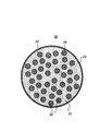
- FIG. 1 schematically shows a cross section of a silicate composite particle 20 coated with a conductive layer as an example of a first silicon-containing material.
- the silicate composite particle (mother particle) 23 includes a lithium silicate phase 21 and a silicon phase 22 dispersed in the lithium silicate phase 21.
- the silicate composite particles (mother particles) 23 have a sea-island structure in which fine silicon phases 22 are dispersed in a matrix of lithium silicate phases 21.
- the surface of the silicate composite particles (mother particles) 23 is coated with the conductive layer 26.
- a silicon oxide phase (not shown) may be dispersed in the lithium silicate phase 21.
- the SiO 2 content in the silicate composite particles (mother particles) 23 measured by Si-NMR is preferably, for example, 30% by mass or less, and more preferably less than 7% by mass.
- the silicate composite particle (mother particle) 23 may contain other components in addition to the above.
- a carbon material, an oxide such as ZrO 2 , and a reinforcing material such as a carbide may be contained in an amount of less than 10% by mass with respect to the mother particle 23.
- the raw material silicon and the carbon source are mixed, and the mixture of the raw material silicon and the carbon source is pulverized and compounded by using a pulverizer such as a ball mill. An organic solvent may be added to the mixture and wet pulverized. At this time, the raw material silicon is finely pulverized to form a second silicon phase. The second silicon phase is dispersed in the matrix of carbon sources.
- Examples of the carbon source include water-soluble resins such as carboxymethyl cellulose (CMC), hydroxyethyl cellulose, polyacrylate, polyacrylamide, polyvinyl alcohol, polyethylene oxide, and polyvinylpyrrolidone, sugars such as cellulose and sucrose, petroleum pitch, and coal pitch. , Tar, etc., but are not particularly limited.
- organic solvent alcohol, ether, fatty acid, alkane, cycloalkane, silicic acid ester, metal alkoxide and the like can be used.
- the composite of the second silicon phase and the carbon source is heated to 700 ° C. to 1200 ° C. in an inert gas atmosphere (for example, an atmosphere of argon, nitrogen, etc.) to carbonize the carbon source to obtain amorphous carbon. Generate.
- an inert gas atmosphere for example, an atmosphere of argon, nitrogen, etc.
- (Ii) Second method The raw material silicon and the carbon material (hereinafter, also referred to as the second carbon material) are mixed, and the mixture of the raw material silicon and the second carbon material is atomized using a crusher such as a ball mill. While crushing and compounding. An organic solvent may be added to the mixture and wet pulverized. At this time, the raw material silicon is finely pulverized to form a second silicon phase. The second silicon phase is dispersed in the matrix of the second carbon material.
- a crusher such as a ball mill. While crushing and compounding.
- An organic solvent may be added to the mixture and wet pulverized.
- the raw material silicon is finely pulverized to form a second silicon phase.
- the second silicon phase is dispersed in the matrix of the second carbon material.
- a second silicon-containing material in which the second silicon is dispersed in the carbon phase of amorphous carbon can be obtained.
- the second silicon-containing material may then be heated to 700 ° C. to 1200 ° C. in an inert gas atmosphere.
- amorphous carbon is preferable, and easily graphitized carbon (soft carbon), non-graphitized carbon (hard carbon), carbon black and the like can be used.
- carbon black include acetylene black and Ketjen black. Even when graphite is used as the second carbon material, the crystal structure of graphite is almost lost when a composite of the second silicon and the carbon material is obtained by using a pulverizer, and a carbon phase of amorphous carbon is formed.
- the secondary battery according to the embodiment of the present invention includes a positive electrode, a negative electrode, an electrolyte, and a separator interposed between the positive electrode and the negative electrode.
- the negative electrode includes a first carbon material, a first silicon-containing material, and a second silicon-containing material.
- the negative electrode, the positive electrode, the electrolyte, and the separator provided in the secondary battery according to the embodiment of the present invention will be described.
- the negative electrode includes, for example, a negative electrode current collector and a negative electrode mixture layer formed on the surface of the negative electrode current collector and containing a negative electrode active material.
- the negative electrode mixture layer can be formed by applying a negative electrode slurry in which the negative electrode mixture is dispersed in a dispersion medium to the surface of the negative electrode current collector and drying it. The dried coating film may be rolled if necessary.
- the negative electrode mixture contains a negative electrode active material as an essential component, and may contain a binder, a conductive agent, a thickener, and the like as optional components.
- the negative electrode active material includes a first carbon material and a first and second silicon-containing material.
- the negative electrode current collector As the negative electrode current collector, a non-perforated conductive substrate (metal foil, etc.) and a porous conductive substrate (mesh body, net body, punching sheet, etc.) are used. Examples of the material of the negative electrode current collector include stainless steel, nickel, nickel alloy, copper, and copper alloy.
- binder examples include fluororesin, polyolefin resin, polyamide resin, polyimide resin, vinyl resin, styrene-butadiene copolymer rubber (SBR), polyacrylic acid and derivatives thereof.
- fluororesin polyolefin resin
- polyamide resin polyamide resin
- polyimide resin polyimide resin
- vinyl resin vinyl resin
- SBR styrene-butadiene copolymer rubber
- polyacrylic acid and derivatives thereof examples include fluororesin, polyolefin resin, polyamide resin, polyimide resin, vinyl resin, styrene-butadiene copolymer rubber (SBR), polyacrylic acid and derivatives thereof.
- SBR styrene-butadiene copolymer rubber
- Examples of the conductive agent include carbon black, conductive fibers, carbon fluoride, and organic conductive materials. One of these may be used alone, or two or more thereof may be used in combination.
- thickener examples include carboxymethyl cellulose (CMC) and polyvinyl alcohol. One of these may be used alone, or two or more thereof may be used in combination.
- CMC carboxymethyl cellulose
- polyvinyl alcohol examples include polyvinyl alcohol. One of these may be used alone, or two or more thereof may be used in combination.
- dispersion medium examples include water, alcohol, ether, N-methyl-2-pyrrolidone (NMP), and a mixed solvent thereof.
- the positive electrode includes, for example, a positive electrode current collector and a positive electrode mixture layer formed on the surface of the positive electrode current collector.
- the positive electrode mixture layer can be formed by applying a positive electrode slurry in which the positive electrode mixture is dispersed in a dispersion medium to the surface of the positive electrode current collector and drying it. The dried coating film may be rolled if necessary.
- the positive electrode mixture contains a positive electrode active material as an essential component, and can contain a binder, a conductive agent, etc. as an optional component.
- a lithium composite metal oxide can be used as the positive electrode active material.
- the lithium composite metal oxide include Li a CoO 2 , Li a NiO 2 , Li a MnO 2 , Li a Co b Ni 1-b O 2 , Li a Co b M 1-b O c , and Li a Ni. 1-b M b O c, Li a Mn 2 O 4, Li a Mn 2-b M b O 4, LiMePO 4, Li 2 MePO 4 F can be mentioned.
- M is at least one selected from the group consisting of Na, Mg, Sc, Y, Mn, Fe, Co, Ni, Cu, Zn, Al, Cr, Pb, Sb, and B.
- Me contains at least a transition element (eg, includes at least one selected from the group consisting of Mn, Fe, Co, Ni).
- a transition element eg, includes at least one selected from the group consisting of Mn, Fe, Co, Ni.
- the value a indicating the molar ratio of lithium is a value immediately after the production of the active material, and increases or decreases depending on charging and discharging.
- the binder and the conductive agent the same ones as those exemplified for the negative electrode can be used.
- the conductive agent graphite such as natural graphite or artificial graphite may be used.
- the positive electrode current collector a conductive substrate similar to the negative electrode current collector can be used.
- the material of the positive electrode current collector include stainless steel, aluminum, aluminum alloy, and titanium.
- the electrolyte (or electrolyte) contains a solvent and a lithium salt dissolved in the solvent.
- concentration of the lithium salt in the electrolyte is, for example, 0.5 to 2 mol / L.
- the electrolyte may contain known additives.
- an aqueous solvent or a non-aqueous solvent is used.
- a non-aqueous solvent for example, a cyclic carbonate ester, a chain carbonate ester, a cyclic carboxylic acid ester, or the like is used.
- the cyclic carbonate include propylene carbonate (PC) and ethylene carbonate (EC).
- the chain carbonic acid ester include diethyl carbonate (DEC), ethyl methyl carbonate (EMC), and dimethyl carbonate (DMC).
- DEC diethyl carbonate
- EMC ethyl methyl carbonate
- DMC dimethyl carbonate
- examples of the cyclic carboxylic acid ester include ⁇ -butyrolactone (GBL) and ⁇ -valerolactone (GVL).
- GBL ⁇ -butyrolactone
- GVL ⁇ -valerolactone
- lithium salt examples include a lithium salt of a chlorine-containing acid (LiClO 4 , LiAlCl 4 , LiB 10 Cl 10, etc.) and a lithium salt of a fluorine-containing acid (LiPF 6 , LiBF 4 , LiSbF 6 , LiAsF 6 , LiCF 3 SO 3). , LiCF 3 CO 2 etc.), Lithium salt of fluorine-containing acid imide (LiN (CF 3 SO 2 ) 2 , LiN (CF 3 SO 2 ) (C 4 F 9 SO 2 ), LiN (C 2 F 5 SO 2 ) 2 etc.), lithium halide (LiCl, LiBr, LiI, etc.) and the like can be used.
- One type of lithium salt may be used alone, or two or more types may be used in combination.
- the separator has high ion permeability and has appropriate mechanical strength and insulation.
- a microporous thin film, a woven fabric, a non-woven fabric, or the like can be used.
- the material of the separator for example, polyolefins such as polypropylene and polyethylene can be used.
- An example of the structure of a secondary battery is a structure in which an electrode group in which a positive electrode and a negative electrode are wound via a separator and an electrolyte are housed in an exterior body.
- another form of electrode group such as a laminated type electrode group in which a positive electrode and a negative electrode are laminated via a separator may be applied.
- the secondary battery may be in any form such as a cylindrical type, a square type, a coin type, a button type, and a laminated type.
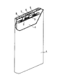
- FIG. 2 is a schematic perspective view in which a part of the square secondary battery according to the embodiment of the present invention is cut out.
- the battery includes a bottomed square battery case 4, an electrode group 1 and an electrolyte (not shown) housed in the battery case 4, and a sealing plate 5 for sealing the opening of the battery case 4.
- the electrode group 1 has a long strip-shaped negative electrode, a long strip-shaped positive electrode, and a separator interposed between them.
- the sealing plate 5 has a liquid injection port closed by the sealing 8 and a negative electrode terminal 6 insulated from the sealing plate 5 by a gasket 7.
- One end of the negative electrode lead 3 is attached to the negative electrode current collector by welding or the like.
- One end of the positive electrode lead 2 is attached to the positive electrode current collector by welding or the like.
- the other end of the negative electrode lead 3 is electrically connected to the negative electrode terminal 6.
- the other end of the positive electrode lead 2 is electrically connected to the sealing plate 5.
- Lithium silicate (Li 2 Si 2 O 5 ) having an average particle size of 10 ⁇ m and raw material silicon (3N, average particle size 10 ⁇ m) were mixed at a mass ratio of 70:30.
- the powdery mixture was taken out in the inert atmosphere and calcined at 800 ° C. for 4 hours in the inert atmosphere under the pressure of a hot press to sinter the mixture (silicon-silicate complex). ) was obtained.
- the silicon-silicate composite was crushed and passed through a mesh of 40 ⁇ m, and then the obtained silicate composite particles were mixed with coal pitch (MCP250 manufactured by JFE Chemical Co., Ltd.), and the mixture was mixed in an inert atmosphere at 800 ° C.
- the surface of the silicate composite particles was coated with conductive carbon to form a conductive layer.
- the coating amount of the conductive layer was set to 5% by mass with respect to the total mass of the silicate composite particles and the conductive layer.
- silicate composite particles (first silicon-containing particles) having a conductive layer and having an average particle size of 10 ⁇ m were obtained.
- the volume-based particle size distribution of the first silicon-containing particles is measured using a laser diffraction type particle size distribution measuring device (MT3300EXII manufactured by Microtrac Co., Ltd.), and the particle size when the cumulative volume is 50% is averaged. The diameter was set.
- the crystallite size of the first silicon phase calculated by Scherrer's equation from the diffraction peak attributed to the Si (111) plane by XRD analysis of the silicate composite particles was 15 nm.
- the Si / Li ratio was 1.0
- the content of Li 2 Si 2 O 5 measured by Si-NMR was 70% by mass ().
- the content of the first silicon phase was 30% by mass).
- Coal pitch as a carbon source MCP250 manufactured by JFE Chemical Co., Ltd.
- raw material silicon 3N, average particle size 10 ⁇ m
- MCP250 manufactured by JFE Chemical Co., Ltd.
- Raw material silicon 3N, average particle size 10 ⁇ m
- the mixture was milled at 200 rpm for 50 hours to give a composite of the second silicon phase and the carbon source.
- the composite of the second silicon phase and the carbon source is calcined in an inert gas atmosphere to carbonize the carbon source, and the second silicon phase is dispersed in the carbon phase containing amorphous carbon. Obtained the material. Then, using a jet mill, secondary silicon-containing particles having an average particle size of 10 ⁇ m were obtained.
- the volume-based particle size distribution of the second silicon-containing particles is measured using a laser diffraction type particle size distribution measuring device (MT3300EXII manufactured by Microtrac Co., Ltd.), and the particle size when the cumulative volume is 50% is averaged. The diameter was set.
- the crystallite size of the second silicon phase calculated by Scherrer's equation from the diffraction peak assigned to the Si (111) plane by XRD analysis of the second silicon-containing particles was 15 nm.
- ⁇ Particle breaking strength The particle breaking strength of the obtained first silicon-containing material or second silicon-containing material was measured. Ten particles each having a particle size of 5 ⁇ m or more and 20 ⁇ m or less obtained in the photographed image were prepared. While gradually increasing the load, the displacement speed was set to 5 ⁇ m / sec, the particles were compressed with a flat indenter having a tip diameter of 50 ⁇ m, and the load when the particles were destroyed was determined. MCT-211 manufactured by Shimadzu Corporation was used as the microcompression tester. The average value of the particle decay intensities of 10 particles was calculated.
- Spherical graphite having an average particle size Dc of 20 ⁇ m was prepared.
- the volume-based particle size distribution of graphite was measured using a laser diffraction type particle size distribution measuring device (MT3300EXII manufactured by Microtrac Co., Ltd.), and the particle size when the cumulative volume was 50% was taken as the average particle size.
- the first silicon-containing particles having a conductive layer, the second silicon-containing particles, and graphite were mixed at a mass ratio of 3: 3: 94 and used as a negative electrode active material.
- the negative electrode active material, sodium carboxymethyl cellulose (CMC-Na), and styrene-butadiene rubber (SBR) are mixed at a mass ratio of 97.5: 1: 1.5, water is added, and then a mixer (mixer (CMC-Na).
- a negative electrode slurry was prepared by stirring using TK hibismix manufactured by Primix.
- a negative electrode slurry is applied to the surface of the copper foil so that the mass of the negative electrode mixture per 1 m 2 is 190 g, the coating film is dried, and then rolled to obtain a density of 1.
- a negative electrode having a negative electrode mixture layer of 5 g / cm 3 formed was obtained.
- Lithium-nickel composite oxide LiNi 0.8 Co 0.18 Al 0.02 O 2
- acetylene black and polyvinylidene fluoride were mixed at a mass ratio of 95: 2.5: 2.5, and N
- stirring was performed using a mixer (TK Hibismix manufactured by Primix Corporation) to prepare a positive electrode slurry.
- TK Hibismix manufactured by Primix Corporation
- a positive electrode slurry is applied to the surface of the aluminum foil, the coating film is dried, and then rolled to obtain a positive electrode having a positive electrode mixture layer having a density of 3.6 g / cm 3 formed on both sides of the aluminum foil.
- An electrolytic solution was prepared by dissolving a lithium salt in a non-aqueous solvent.
- a non-aqueous solvent a mixed solvent containing ethylene carbonate (EC), dimethyl carbonate (DMC), and methyl acetate (MA) in a volume ratio of 20:40:40 was used.
- the concentration of LiPF 6 in the electrolytic solution was 1.0 mol / L.
- Electrode group was inserted into an aluminum laminate film outer body, vacuum dried at 105 ° C. for 2 hours, then an electrolytic solution was injected to seal the opening of the outer body to obtain a battery A1.
- Examples 2 to 4 and Comparative Examples 1 to 3 Similar to Example 1, the batteries A2, A3, A4 of Examples 2, 3 and 4 and the batteries B1, B2 of Comparative Examples 1, 2 and 3 except that the negative electrode active material having the composition shown in Table 1 was used. B3 was prepared. In Table 1 (and Tables 2 and 3 described later), the first silicon-containing material is referred to as a first Si material, and the second silicon-containing material is referred to as a second Si material. In the battery A4, the particle breaking strength Mb was controlled by changing the firing temperature.
- Each battery produced above was evaluated by the following method. Each of the manufactured batteries was constantly charged with a current of 0.3 It until the voltage reached 4.2 V, and then charged with a constant voltage of 4.2 V until the current reached 0.015 It. Then, a constant current discharge was performed with a current of 0.3 It until the voltage became 2.75 V. The pause period between charging and discharging was 10 minutes. Charging and discharging was performed in an environment of 25 ° C.
- (1 / X) It represents a current
- (1 / X) It (A) rated capacity (Ah) / X (h)
- X is for charging or discharging electricity corresponding to the rated capacity.
- Charging and discharging were repeated under the above charging and discharging conditions.
- the ratio (percentage) of the discharge capacity at the 300th cycle to the discharge capacity at the first cycle was determined as the capacity retention rate in the charge / discharge cycle.
- the evaluation results are shown in Table 1 together with the information on the particle breaking strength.
- Examples 5 to 7 and Comparative Examples 4 and 5 Batteries A5, A6, A7 of Examples 5, 6 and 7 and batteries B4 and B5 of Comparative Examples 4 and 5 were prepared in the same manner as in Example 1 except that the negative electrode active material having the composition shown in Table 2 was used. , The same evaluation was performed. Here, the particle breaking strength Ma was controlled by the applied pressure of the hot press, and Mb was controlled by the firing temperature.
- Examples 8 and 9 and Comparative Examples 6 and 7 Batteries A8 and A9 of Examples 8 and 9 and batteries B6 and B7 of Comparative Examples 6 and 7 were prepared and evaluated in the same manner as in Example 1 except that the negative electrode active material having the composition shown in Table 3 was used. Was done. Here, the particle breaking strength Ma was controlled by the applied pressure of the hot press, and Mb was controlled by the firing temperature.
- the secondary battery according to the present invention is useful as a main power source for mobile communication devices, portable electronic devices, and the like.
- Electrode group 2 Positive electrode lead 3: Negative electrode lead 4: Battery case 5: Seal plate, 6: Negative terminal terminal, 7: Gasket, 8: Seal, 20: Silicate composite particles coated with conductive layer , 21: Lithium silicate phase, 22: First silicon phase, 23: Silicate composite particles, 26: Conductive layer
Landscapes
- Chemical & Material Sciences (AREA)
- Chemical Kinetics & Catalysis (AREA)
- Electrochemistry (AREA)
- General Chemical & Material Sciences (AREA)
- Composite Materials (AREA)
- Inorganic Chemistry (AREA)
- Battery Electrode And Active Subsutance (AREA)
Abstract
Description
<SEM-EDX測定条件>
加工装置:JEOL製、SM-09010(Cross Section Polisher)
加工条件:加速電圧6kV
電流値:140μA
真空度:1×10⁻³~2×10⁻³Pa
測定装置:電子顕微鏡HITACHI製SU-70
分析時加速電圧:10kV
フィールド:フリーモード
プローブ電流モード:Medium
プローブ電流範囲:High
アノード Ap.:3
OBJ Ap.:2
分析エリア:1μm四方
分析ソフト:EDAX Genesis
CPS:20500
Lsec:50
時定数:3.2
<Si-NMR測定条件>
測定装置:バリアン社製、固体核磁気共鳴スペクトル測定装置(INOVA‐400)
プローブ:Varian 7mm CPMAS-2
MAS:4.2kHz
MAS速度:4kHz
パルス:DD(45°パルス+シグナル取込時間1Hデカップル)
繰り返し時間:1200sec~3000sec
観測幅:100kHz
観測中心:-100ppm付近
シグナル取込時間:0.05sec
積算回数:560
試料量:207.6mg
リチウムシリケートの原料には、Si原料と、Li原料とを所定の割合で含む原料混合物を用いる。原料混合物に、上述のアルカリ金属元素、第II族元素、および/または、元素Mを含ませてもよい。原料混合物を溶解し、融液を金属ロールに通してフレーク化してリチウムシリケートを作製する。その後フレーク化したシリケートを大気雰囲気で、ガラス転移点以上、融点以下の温度で熱処理により結晶化させる。なお、フレーク化したシリケートは結晶化させずに使用することも可能である。原料混合物を溶解せずに、融点以下の温度で焼成して固相反応によりシリケートを製造することも可能である。
次に、リチウムシリケートに原料シリコンを配合して複合化を行う。例えば、以下の工程(a)~(c)を経てリチウムシリケートと第1シリコン相との複合粒子(以下、シリケート複合粒子とも称する。)である第1ケイ素含有材料が作製される。
原料シリコンの粉末とリチウムシリケートの粉末とを、例えば、20:80~95:5の質量比で混合する。原料シリコンには平均粒径が数μm~数十μm程度のシリコンの粗粒子を用いればよい。
次に、ボールミルのような粉砕装置を用いて、原料シリコンとリチウムシリケートの混合物を微粒子化しながら粉砕および複合化する。このとき、混合物に有機溶媒を添加して、湿式粉砕してもよい。有機溶媒は、粉砕対象物の粉砕容器の内壁への付着を防ぐ役割を果たす。
次に、混合物を、例えば不活性ガス雰囲気(例えばアルゴン、窒素などの雰囲気)中で600℃~1000℃に加熱された状態で加圧し、焼結させる。焼結には、ホットプレスなど、不活性雰囲気下で加圧できる焼結装置を用い得る。焼結時、シリケートが軟化し、第1シリコン相間の隙間を埋めるように流動する。その結果、シリケート相を海部とし、第1シリコン相を島部とする緻密なブロック状の焼結体を得ることができる。得られた焼結体を粉砕すれば、シリケート複合粒子が得られる。
引き続き、複合粒子の表面の少なくとも一部を導電性材料で被覆して導電層を形成してもよい。導電性炭素材料で複合粒子の表面を被覆する方法としては、アセチレン、メタンなどの炭化水素ガスを原料に用いるCVD法、石炭ピッチ、石油ピッチ、フェノール樹脂などを複合粒子と混合し、不活性雰囲気(例えば、アルゴン、窒素などの雰囲気)中で、700℃~950℃で加熱して炭化させる方法などが例示できる。また、カーボンブラックを複合粒子の表面に付着させてもよい。
複合粒子(表面に導電層を有する場合を含む。)を酸で洗浄する工程を行ってもよい。例えば、酸性水溶液で複合粒子を洗浄することで、原料シリコンとリチウムシリケートとを複合化させる際に生じ得る微量のアルカリ成分を溶解させ、除去することができる。酸性水溶液としては、塩酸、フッ化水素酸、硫酸、硝酸、リン酸、炭酸などの無機酸の水溶液や、クエン酸、酢酸などの有機酸の水溶液を用いることができる。
(i)第1の方法
原料シリコンと炭素源とを混合し、ボールミルのような粉砕装置を用いて、原料シリコンと炭素源の混合物を微粒子化しながら粉砕および複合化する。混合物に有機溶媒を添加して、湿式粉砕してもよい。このとき、原料シリコンが微粉砕されて第2シリコン相が生成する。第2シリコン相は、炭素源のマトリックスに分散する。
原料シリコンと炭素材料(以下、第2炭素材料とも称する。)を混合し、ボールミルのような粉砕装置を用いて、原料シリコンと第2炭素材料との混合物を微粒子化しながら粉砕および複合化する。混合物に有機溶媒を添加して、湿式粉砕してもよい。このとき、原料シリコンが微粉砕されて第2シリコン相が生成する。第2シリコン相は、第2炭素材料のマトリックスに分散する。
負極は、例えば、負極集電体と、負極集電体の表面に形成され、かつ負極活物質を含む負極合材層とを具備する。負極合材層は、負極合材を分散媒に分散させた負極スラリーを、負極集電体の表面に塗布し、乾燥させることにより形成できる。乾燥後の塗膜を、必要により圧延してもよい。
正極は、例えば、正極集電体と、正極集電体の表面に形成された正極合材層とを具備する。正極合材層は、正極合材を分散媒に分散させた正極スラリーを、正極集電体の表面に塗布し、乾燥させることにより形成できる。乾燥後の塗膜を、必要により圧延してもよい。
電解質(もしくは電解液)は、溶媒と、溶媒に溶解したリチウム塩を含む。電解質におけるリチウム塩の濃度は、例えば、0.5~2mol/Lである。電解質は、公知の添加剤を含有してもよい。
正極と負極との間には、セパレータを介在させることが望ましい。セパレータは、イオン透過度が高く、適度な機械的強度および絶縁性を備えている。セパレータとしては、微多孔薄膜、織布、不織布などを用いることができる。セパレータの材質としては、例えば、ポリプロピレン、ポリエチレンなどのポリオレフィンが用いられ得る。
[第1ケイ素含有材料の調製]
二酸化ケイ素と炭酸リチウムとを原子比:Si/Liが1.05となるように混合し、混合物を950℃空気中で10時間焼成することにより、式:Li2Si2O5(z=0.5)で表わされるリチウムシリケートを得た。得られたリチウムシリケートは平均粒径10μmになるように粉砕した。
炭素源の石炭ピッチ(JFEケミカル株式会社製、MCP250)と、原料シリコン(3N、平均粒径10μm)とを、50:50の質量比で混合した。混合物を遊星ボールミル(フリッチュ社製、P-5)のポット(SUS製、容積:500mL)に充填し、ポットにSUS製ボール(直径20mm)を24個入れて蓋を閉め、不活性雰囲気中で、200rpmで混合物を50時間粉砕処理し、第2シリコン相と炭素源との複合物を得た。
得られた第1ケイ素含有材料または第2ケイ素含有材料の粒子破壊強度を測定した。撮影画像で得られる粒径が5μm以上、20μm以下の粒子をそれぞれ10個ずつ準備した。荷重を徐々に大きくしながら、変位速度を5μm/secとして、先端径が50μmのフラット圧子で粒子を圧縮し、粒子が破壊に至るときの荷重を求めた。微小圧縮試験器として(株)島津製作所製のMCT-211を用いた。10個の粒子の粒子破壊強度の平均値を求めた。
平均粒径Dcが20μmの球状の黒鉛を準備した。ここでは黒鉛の体積基準の粒度分布を、レーザー回折式粒度分布測定装置(株式会社マイクロトラック製のMT3300EXII)を用いて測定し、累積体積50%のときの粒径を平均粒径とした。
導電層を有する第1ケイ素含有粒子と、第2ケイ素含有粒子と、黒鉛とを、3:3:94の質量比で混合し、負極活物質として用いた。負極活物質と、カルボキシメチルセルロースナトリウム(CMC-Na)と、スチレン-ブタジエンゴム(SBR)とを、97.5:1:1.5の質量比で混合し、水を添加した後、混合機(プライミクス社製、T.K.ハイビスミックス)を用いて攪拌し、負極スラリーを調製した。
リチウムニッケル複合酸化物(LiNi0.8Co0.18Al0.02O2)と、アセチレンブラックと、ポリフッ化ビニリデンとを、95:2.5:2.5の質量比で混合し、N-メチル-2-ピロリドン(NMP)を添加した後、混合機(プライミクス社製、T.K.ハイビスミックス)を用いて攪拌し、正極スラリーを調製した。次に、アルミニウム箔の表面に正極スラリーを塗布し、塗膜を乾燥させた後、圧延して、アルミニウム箔の両面に、密度3.6g/cm3の正極合材層が形成された正極を作製した。
非水溶媒にリチウム塩を溶解させて電解液を調製した。非水溶媒には、エチレンカーボネート(EC)と、ジメチルカーボネート(DMC)と、酢酸メチル(MA)とを、20:40:40の体積比で含む混合溶媒を用いた。電解液中のLiPF6の濃度は1.0mol/Lとした。
各電極にタブをそれぞれ取り付け、タブが最外周部に位置するように、セパレータを介して正極および負極を渦巻き状に巻回することにより電極群を作製した。電極群をアルミニウムラミネートフィルム製の外装体内に挿入し、105℃で2時間真空乾燥した後、電解液を注入し、外装体の開口部を封止して、電池A1を得た。
表1に示す組成の負極活物質を用いたこと以外、実施例1と同様に、実施例2、3、4の電池A2、A3、A4および比較例1、2、3の電池B1、B2、B3を作製した。表1(および後述の表2、3)では、第1ケイ素含有材料を第1Si材料、第2ケイ素含有材料を第2Si材料と表示する。なお、電池A4では、焼成温度を変更することにより粒子破壊強度Mbを制御した。
上記で作製した各電池について、以下の方法で評価を行った。
作製後の各電池について、0.3Itの電流で電圧が4.2Vになるまで定電流充電を行い、その後、4.2Vの定電圧で電流が0.015Itになるまで定電圧充電した。その後、0.3Itの電流で電圧が2.75Vになるまで定電流放電を行った。充電と放電との間の休止期間は10分とした。充放電は25℃の環境下で行った。
上記充放電の条件で充放電を繰り返した。1サイクル目の放電容量に対する300サイクル目の放電容量の割合(百分率)を、充放電サイクルにおける容量維持率として求めた。評価結果を粒子破壊強度の情報とともに表1に示す。

表2に示す組成の負極活物質を用いたこと以外、実施例1と同様に、実施例5、6、7の電池A5、A6、A7および比較例4、5の電池B4、B5を作製し、同様に評価を行った。ここでは、ホットプレスの印加圧力により粒子破壊強度Maを、焼成温度によってMbを制御した。

表3に示す組成の負極活物質を用いたこと以外、実施例1と同様に、実施例8、9の電池A8、A9および比較例6、7の電池B6、B7を作製し、同様に評価を行った。ここでは、ホットプレスの印加圧力により粒子破壊強度Maを、焼成温度によってMbを制御した。

Claims (9)
- 正極と、負極と、電解質と、を備え、
前記負極は、炭素材料と、第1ケイ素含有材料と、第2ケイ素含有材料と、を含み、
前記第1ケイ素含有材料は、シリケート相と、前記シリケート相内に分散している第1シリコン相と、を含み、
前記第2ケイ素含有材料は、炭素相と、前記炭素相内に分散している第2シリコン相と、を含む、二次電池。 - 前記第1ケイ素含有材料の質量Aに対する前記第2ケイ素含有材料の質量Bの比:B/Aが、0.2<B/A<10を満たす、請求項1に記載の二次電池。
- 前記第1ケイ素含有材料の質量Aと前記第2ケイ素含有材料の質量Bと前記炭素材料の質量Cとの合計に対する、前記第1ケイ素含有材料の質量Aと前記第2ケイ素含有材料の質量Bとの合計の割合が、5質量%以上、30質量%以下である、請求項1または2に記載の二次電池。
- 前記シリケート相は、アルカリ金属元素および第II族元素からなる群より選択される少なくとも1種を含む、請求項1~3のいずれか1項に記載の二次電池。
- 前記シリケート相は、さらに元素Mを含み、
前記元素Mは、B、Al、Zr、Nb、Ta、V、La、Y、Ti、P、Bi、Zn、Sn、Pb、Sb、Co、Er、FおよびWからなる群より選択される少なくとも1種である、請求項4に記載の二次電池。 - 前記シリケート相は、式:Li2zSiO2+z(0<z<2)で表されるリチウムシリケートを含む、請求項4または5に記載の二次電池。
- 前記第1ケイ素含有材料の粒子破壊強度Maが、300MPa<Ma<1000MPaである、請求項1~6のいずれか1項に記載の二次電池。
- 前記第2ケイ素含有材料の粒子破壊強度Mbが、300MPa<Mb<1000MPaである、請求項1~7のいずれか1項に記載の二次電池。
- 前記第1ケイ素含有材料の前記粒子破壊強度Maに対する、前記第2ケイ素含有材料の粒子破壊強度Mbの比:Mb/Maが、0.5<Mb/Ma<2を満たす、請求項8に記載の二次電池。
Priority Applications (4)
| Application Number | Priority Date | Filing Date | Title |
|---|---|---|---|
| US17/914,518 US12609305B2 (en) | 2020-03-30 | 2021-03-22 | Secondary battery |
| JP2022511960A JP7710186B2 (ja) | 2020-03-30 | 2021-03-22 | 二次電池 |
| CN202180024807.7A CN115552676A (zh) | 2020-03-30 | 2021-03-22 | 二次电池 |
| EP21780453.3A EP4131490B1 (en) | 2020-03-30 | 2021-03-22 | Secondary battery |
Applications Claiming Priority (2)
| Application Number | Priority Date | Filing Date | Title |
|---|---|---|---|
| JP2020061377 | 2020-03-30 | ||
| JP2020-061377 | 2020-03-30 |
Publications (1)
| Publication Number | Publication Date |
|---|---|
| WO2021200343A1 true WO2021200343A1 (ja) | 2021-10-07 |
Family
ID=77930347
Family Applications (1)
| Application Number | Title | Priority Date | Filing Date |
|---|---|---|---|
| PCT/JP2021/011755 Ceased WO2021200343A1 (ja) | 2020-03-30 | 2021-03-22 | 二次電池 |
Country Status (5)
| Country | Link |
|---|---|
| US (1) | US12609305B2 (ja) |
| EP (1) | EP4131490B1 (ja) |
| JP (1) | JP7710186B2 (ja) |
| CN (1) | CN115552676A (ja) |
| WO (1) | WO2021200343A1 (ja) |
Cited By (4)
| Publication number | Priority date | Publication date | Assignee | Title |
|---|---|---|---|---|
| CN116417581A (zh) * | 2021-12-31 | 2023-07-11 | 贝特瑞新材料集团股份有限公司 | 负极材料及其制备方法、锂离子电池 |
| WO2024024885A1 (ja) * | 2022-07-29 | 2024-02-01 | パナソニックエナジー株式会社 | 二次電池 |
| WO2024116784A1 (ja) * | 2022-11-28 | 2024-06-06 | パナソニックエナジー株式会社 | 非水電解質二次電池 |
| WO2025115777A1 (ja) * | 2023-11-30 | 2025-06-05 | パナソニックIpマネジメント株式会社 | 非水電解質二次電池 |
Families Citing this family (1)
| Publication number | Priority date | Publication date | Assignee | Title |
|---|---|---|---|---|
| JP2025540238A (ja) * | 2023-03-06 | 2025-12-11 | 香港時代新能源科技有限公司 | シリコン系負極活物質、二次電池及び電気装置 |
Citations (5)
| Publication number | Priority date | Publication date | Assignee | Title |
|---|---|---|---|---|
| JP2014044899A (ja) * | 2012-08-28 | 2014-03-13 | Toyota Industries Corp | 非水電解質二次電池用負極材料、その製造方法、非水電解質二次電池用負極及び非水電解質二次電池 |
| JP2014071948A (ja) * | 2012-09-27 | 2014-04-21 | Sanyo Electric Co Ltd | 負極活物質の製造方法 |
| WO2015145521A1 (ja) * | 2014-03-24 | 2015-10-01 | 株式会社 東芝 | 非水電解質電池用負極活物質、非水電解質二次電池用負極、非水電解質二次電池及び電池パック |
| WO2016035290A1 (ja) | 2014-09-03 | 2016-03-10 | 三洋電機株式会社 | 非水電解質二次電池用負極活物質及び非水電解質二次電池 |
| WO2016147564A1 (ja) * | 2015-03-13 | 2016-09-22 | 三洋電機株式会社 | 非水電解質二次電池 |
Family Cites Families (31)
| Publication number | Priority date | Publication date | Assignee | Title |
|---|---|---|---|---|
| JP4533822B2 (ja) | 2005-08-24 | 2010-09-01 | 株式会社東芝 | 非水電解質電池および負極活物質 |
| JP2008152996A (ja) | 2006-12-15 | 2008-07-03 | Sony Corp | 電池 |
| JP2010165471A (ja) | 2009-01-13 | 2010-07-29 | Sanyo Electric Co Ltd | リチウム二次電池 |
| JP5481904B2 (ja) | 2009-03-30 | 2014-04-23 | 日産自動車株式会社 | リチウムイオン二次電池用負極およびこれを用いたリチウムイオン二次電池 |
| US8889298B2 (en) | 2011-08-30 | 2014-11-18 | Nanotek Instruments, Inc. | Surface-mediated lithium ion-exchanging energy storage device |
| US20120171560A1 (en) * | 2012-02-01 | 2012-07-05 | Electrochemical Materials, LLC | Silicon and lithium silicate composite anodes for lithium rechargeable batteries and preparation method thereof |
| US20130230769A1 (en) * | 2012-02-01 | 2013-09-05 | Electrochemical Materials | Silicon and lithium silicate composite anodes for lithium rechargeable batteries |
| JP5831268B2 (ja) | 2012-02-07 | 2015-12-09 | 株式会社豊田自動織機 | 二次電池用活物質およびその製造方法 |
| JP2013178913A (ja) | 2012-02-28 | 2013-09-09 | Hitachi Maxell Ltd | 非水電解液二次電池 |
| CN102820451A (zh) | 2012-07-23 | 2012-12-12 | 深圳市海太阳实业有限公司 | 负极极片及其制备方法、锂离子电池及其制备方法 |
| WO2014054792A1 (ja) | 2012-10-05 | 2014-04-10 | ソニー株式会社 | 活物質、活物質の製造方法、電極および二次電池 |
| JP5636526B2 (ja) * | 2013-02-25 | 2014-12-10 | 株式会社豊田自動織機 | リチウムイオン二次電池及びその製造方法 |
| CN104347842B (zh) | 2013-07-23 | 2017-08-25 | 华为技术有限公司 | 一种锂离子二次电池复合负极片及其制备方法和锂离子二次电池 |
| CN103400971B (zh) | 2013-07-29 | 2016-07-06 | 宁德新能源科技有限公司 | 硅基复合材料及其制备方法以及其应用 |
| WO2016121321A1 (ja) * | 2015-01-28 | 2016-08-04 | 三洋電機株式会社 | 非水電解質二次電池用負極活物質及び非水電解質二次電池 |
| US10312516B2 (en) | 2015-01-28 | 2019-06-04 | Sanyo Electric Co., Ltd. | Negative-electrode active material for non-aqueous electrolyte secondary battery, and non-aqueous electrolyte secondary battery |
| US10177403B2 (en) | 2015-02-23 | 2019-01-08 | Sanyo Electric Co., Ltd. | Negative-electrode active material for non-aqueous electrolyte secondary battery, negative electrode for non-aqueous electrolyte secondary battery, and non-aqueous electrolyte secondary battery |
| JP6597793B2 (ja) | 2015-12-03 | 2019-10-30 | 株式会社村田製作所 | 二次電池、電池パック、電動車両、電力貯蔵システム、電動工具および電子機器 |
| JP6433442B2 (ja) | 2016-01-04 | 2018-12-05 | 信越化学工業株式会社 | 非水電解質二次電池用負極活物質、非水電解質二次電池用負極、及び非水電解質二次電池、並びに非水電解質二次電池用負極活物質の製造方法 |
| EP3343677B1 (en) * | 2016-06-02 | 2023-08-02 | LG Energy Solution, Ltd. | Cathode active material, cathode comprising same, and lithium secondary battery comprising same |
| JP6564740B2 (ja) | 2016-07-04 | 2019-08-21 | 信越化学工業株式会社 | 負極活物質、負極、リチウムイオン二次電池、リチウムイオン二次電池の使用方法、負極活物質の製造方法及びリチウムイオン二次電池の製造方法 |
| WO2018042361A1 (en) | 2016-09-02 | 2018-03-08 | Eocell Limited | Volume change compensated silicon-silicon oxide-lithium composite material having nano silicon particles embedded in a silicon: silicon lithium silicate composite matrix, and cyclical ex-situ manufacturing processes |
| WO2018139288A1 (ja) * | 2017-01-30 | 2018-08-02 | パナソニックIpマネジメント株式会社 | 非水電解質二次電池 |
| CN110313089B (zh) | 2017-03-31 | 2023-04-14 | 松下控股株式会社 | 非水电解质二次电池用负极和非水电解质二次电池 |
| JP6897253B2 (ja) | 2017-04-10 | 2021-06-30 | トヨタ自動車株式会社 | リチウムイオン二次電池用負極 |
| US10804530B2 (en) * | 2017-08-03 | 2020-10-13 | Nanograf Corporation | Composite anode material including surface-stabilized active material particles and methods of making same |
| WO2019151814A1 (ko) | 2018-01-31 | 2019-08-08 | 주식회사 엘지화학 | 음극 활물질, 이를 포함하는 음극 및 리튬 이차전지 |
| EP3806218B1 (en) | 2018-06-01 | 2024-09-04 | Panasonic Intellectual Property Management Co., Ltd. | Secondary battery |
| JP7372244B2 (ja) | 2018-08-07 | 2023-10-31 | パナソニックホールディングス株式会社 | 非水電解質二次電池 |
| JP7478973B2 (ja) * | 2018-12-21 | 2024-05-08 | パナソニックIpマネジメント株式会社 | 二次電池用負極活物質および二次電池 |
| CN113646921B (zh) * | 2019-03-29 | 2024-07-19 | 松下知识产权经营株式会社 | 非水电解质二次电池 |
-
2021
- 2021-03-22 WO PCT/JP2021/011755 patent/WO2021200343A1/ja not_active Ceased
- 2021-03-22 JP JP2022511960A patent/JP7710186B2/ja active Active
- 2021-03-22 US US17/914,518 patent/US12609305B2/en active Active
- 2021-03-22 EP EP21780453.3A patent/EP4131490B1/en active Active
- 2021-03-22 CN CN202180024807.7A patent/CN115552676A/zh active Pending
Patent Citations (5)
| Publication number | Priority date | Publication date | Assignee | Title |
|---|---|---|---|---|
| JP2014044899A (ja) * | 2012-08-28 | 2014-03-13 | Toyota Industries Corp | 非水電解質二次電池用負極材料、その製造方法、非水電解質二次電池用負極及び非水電解質二次電池 |
| JP2014071948A (ja) * | 2012-09-27 | 2014-04-21 | Sanyo Electric Co Ltd | 負極活物質の製造方法 |
| WO2015145521A1 (ja) * | 2014-03-24 | 2015-10-01 | 株式会社 東芝 | 非水電解質電池用負極活物質、非水電解質二次電池用負極、非水電解質二次電池及び電池パック |
| WO2016035290A1 (ja) | 2014-09-03 | 2016-03-10 | 三洋電機株式会社 | 非水電解質二次電池用負極活物質及び非水電解質二次電池 |
| WO2016147564A1 (ja) * | 2015-03-13 | 2016-09-22 | 三洋電機株式会社 | 非水電解質二次電池 |
Non-Patent Citations (1)
| Title |
|---|
| See also references of EP4131490A4 |
Cited By (8)
| Publication number | Priority date | Publication date | Assignee | Title |
|---|---|---|---|---|
| CN116417581A (zh) * | 2021-12-31 | 2023-07-11 | 贝特瑞新材料集团股份有限公司 | 负极材料及其制备方法、锂离子电池 |
| JP2024509865A (ja) * | 2021-12-31 | 2024-03-05 | 貝特瑞新材料集団股▲ふん▼有限公司 | 負極材料及びその製造方法、並びにリチウムイオン電池 |
| EP4273965A4 (en) * | 2021-12-31 | 2025-03-26 | Btr New Material Group Co., Ltd. | Negative electrode material and manufacturing method therefor, as well as lithium-ion battery |
| JP7802085B2 (ja) | 2021-12-31 | 2026-01-19 | 貝特瑞新材料集団股▲ふん▼有限公司 | 負極材料及びその製造方法、並びにリチウムイオン電池 |
| KR102940803B1 (ko) | 2021-12-31 | 2026-03-18 | 비티알 뉴 머티리얼 그룹 코., 엘티디. | 음극 소재 및 그의 제조 방법, 리튬 이온 배터리 |
| WO2024024885A1 (ja) * | 2022-07-29 | 2024-02-01 | パナソニックエナジー株式会社 | 二次電池 |
| WO2024116784A1 (ja) * | 2022-11-28 | 2024-06-06 | パナソニックエナジー株式会社 | 非水電解質二次電池 |
| WO2025115777A1 (ja) * | 2023-11-30 | 2025-06-05 | パナソニックIpマネジメント株式会社 | 非水電解質二次電池 |
Also Published As
| Publication number | Publication date |
|---|---|
| EP4131490A4 (en) | 2024-04-10 |
| EP4131490A1 (en) | 2023-02-08 |
| CN115552676A (zh) | 2022-12-30 |
| JP7710186B2 (ja) | 2025-07-18 |
| JPWO2021200343A1 (ja) | 2021-10-07 |
| US20230132836A1 (en) | 2023-05-04 |
| EP4131490B1 (en) | 2025-05-07 |
| US12609305B2 (en) | 2026-04-21 |
Similar Documents
| Publication | Publication Date | Title |
|---|---|---|
| JPWO2020129652A1 (ja) | 二次電池用負極活物質および二次電池 | |
| JP7710186B2 (ja) | 二次電池 | |
| WO2023053947A1 (ja) | 二次電池 | |
| WO2023053946A1 (ja) | 二次電池 | |
| WO2021153077A1 (ja) | 二次電池用負極活物質およびその製造方法、ならびに二次電池 | |
| CN112119520B (zh) | 二次电池用负极活性物质和二次电池 | |
| CN115398674B (zh) | 二次电池用负极活性物质和使用其的二次电池 | |
| CN114902447B (zh) | 二次电池用负极活性物质及二次电池 | |
| US12119481B2 (en) | Negative electrode active material for secondary batteries and secondary battery | |
| WO2023171580A1 (ja) | 二次電池用負極活物質および二次電池 | |
| CN117999671A (zh) | 二次电池用负极活性物质及其制造方法、以及二次电池 | |
| WO2021153078A1 (ja) | 二次電池用負極活物質および二次電池 | |
| JP7417902B2 (ja) | 二次電池用負極活物質および二次電池 | |
| WO2022113499A1 (ja) | 非水電解質二次電池用負極活物質および非水電解質二次電池 | |
| US20240234722A9 (en) | Negative electrode active material for secondary battery, and secondary battery using same |
Legal Events
| Date | Code | Title | Description |
|---|---|---|---|
| 121 | Ep: the epo has been informed by wipo that ep was designated in this application |
Ref document number: 21780453 Country of ref document: EP Kind code of ref document: A1 |
|
| ENP | Entry into the national phase |
Ref document number: 2022511960 Country of ref document: JP Kind code of ref document: A |
|
| NENP | Non-entry into the national phase |
Ref country code: DE |
|
| ENP | Entry into the national phase |
Ref document number: 2021780453 Country of ref document: EP Effective date: 20221031 |
|
| WWG | Wipo information: grant in national office |
Ref document number: 2021780453 Country of ref document: EP |
|
| WWG | Wipo information: grant in national office |
Ref document number: 202247060241 Country of ref document: IN |