WO2021200426A1 - バリアフィルム、波長変換シート、バックライト、及び表示装置 - Google Patents
バリアフィルム、波長変換シート、バックライト、及び表示装置 Download PDFInfo
- Publication number
- WO2021200426A1 WO2021200426A1 PCT/JP2021/012117 JP2021012117W WO2021200426A1 WO 2021200426 A1 WO2021200426 A1 WO 2021200426A1 JP 2021012117 W JP2021012117 W JP 2021012117W WO 2021200426 A1 WO2021200426 A1 WO 2021200426A1
- Authority
- WO
- WIPO (PCT)
- Prior art keywords
- layer
- wavelength conversion
- barrier
- barrier film
- conversion sheet
- Prior art date
- Legal status (The legal status is an assumption and is not a legal conclusion. Google has not performed a legal analysis and makes no representation as to the accuracy of the status listed.)
- Ceased
Links
Images
Classifications
-
- G—PHYSICS
- G02—OPTICS
- G02F—OPTICAL DEVICES OR ARRANGEMENTS FOR THE CONTROL OF LIGHT BY MODIFICATION OF THE OPTICAL PROPERTIES OF THE MEDIA OF THE ELEMENTS INVOLVED THEREIN; NON-LINEAR OPTICS; FREQUENCY-CHANGING OF LIGHT; OPTICAL LOGIC ELEMENTS; OPTICAL ANALOGUE/DIGITAL CONVERTERS
- G02F1/00—Devices or arrangements for the control of the intensity, colour, phase, polarisation or direction of light arriving from an independent light source, e.g. switching, gating or modulating; Non-linear optics
- G02F1/01—Devices or arrangements for the control of the intensity, colour, phase, polarisation or direction of light arriving from an independent light source, e.g. switching, gating or modulating; Non-linear optics for the control of the intensity, phase, polarisation or colour
- G02F1/13—Devices or arrangements for the control of the intensity, colour, phase, polarisation or direction of light arriving from an independent light source, e.g. switching, gating or modulating; Non-linear optics for the control of the intensity, phase, polarisation or colour based on liquid crystals, e.g. single liquid crystal display cells
- G02F1/133—Constructional arrangements; Operation of liquid crystal cells; Circuit arrangements
- G02F1/1333—Constructional arrangements; Manufacturing methods
- G02F1/1335—Structural association of cells with optical devices, e.g. polarisers or reflectors
- G02F1/1336—Illuminating devices
- G02F1/133614—Illuminating devices using photoluminescence, e.g. phosphors illuminated by UV or blue light
-
- C—CHEMISTRY; METALLURGY
- C08—ORGANIC MACROMOLECULAR COMPOUNDS; THEIR PREPARATION OR CHEMICAL WORKING-UP; COMPOSITIONS BASED THEREON
- C08J—WORKING-UP; GENERAL PROCESSES OF COMPOUNDING; AFTER-TREATMENT NOT COVERED BY SUBCLASSES C08B, C08C, C08F, C08G or C08H
- C08J7/00—Chemical treatment or coating of shaped articles made of macromolecular substances
- C08J7/04—Coating
- C08J7/042—Coating with two or more layers, where at least one layer of a composition contains a polymer binder
- C08J7/0423—Coating with two or more layers, where at least one layer of a composition contains a polymer binder with at least one layer of inorganic material and at least one layer of a composition containing a polymer binder
-
- B—PERFORMING OPERATIONS; TRANSPORTING
- B32—LAYERED PRODUCTS
- B32B—LAYERED PRODUCTS, i.e. PRODUCTS BUILT-UP OF STRATA OF FLAT OR NON-FLAT, e.g. CELLULAR OR HONEYCOMB, FORM
- B32B27/00—Layered products comprising a layer of synthetic resin
- B32B27/06—Layered products comprising a layer of synthetic resin as the main or only constituent of a layer, which is next to another layer of the same or of a different material
- B32B27/08—Layered products comprising a layer of synthetic resin as the main or only constituent of a layer, which is next to another layer of the same or of a different material of synthetic resin
-
- B—PERFORMING OPERATIONS; TRANSPORTING
- B32—LAYERED PRODUCTS
- B32B—LAYERED PRODUCTS, i.e. PRODUCTS BUILT-UP OF STRATA OF FLAT OR NON-FLAT, e.g. CELLULAR OR HONEYCOMB, FORM
- B32B27/00—Layered products comprising a layer of synthetic resin
- B32B27/36—Layered products comprising a layer of synthetic resin comprising polyesters
-
- B—PERFORMING OPERATIONS; TRANSPORTING
- B32—LAYERED PRODUCTS
- B32B—LAYERED PRODUCTS, i.e. PRODUCTS BUILT-UP OF STRATA OF FLAT OR NON-FLAT, e.g. CELLULAR OR HONEYCOMB, FORM
- B32B27/00—Layered products comprising a layer of synthetic resin
- B32B27/40—Layered products comprising a layer of synthetic resin comprising polyurethanes
-
- B—PERFORMING OPERATIONS; TRANSPORTING
- B32—LAYERED PRODUCTS
- B32B—LAYERED PRODUCTS, i.e. PRODUCTS BUILT-UP OF STRATA OF FLAT OR NON-FLAT, e.g. CELLULAR OR HONEYCOMB, FORM
- B32B7/00—Layered products characterised by the relation between layers; Layered products characterised by the relative orientation of features between layers, or by the relative values of a measurable parameter between layers, i.e. products comprising layers having different physical, chemical or physicochemical properties; Layered products characterised by the interconnection of layers
- B32B7/04—Interconnection of layers
- B32B7/12—Interconnection of layers using interposed adhesives or interposed materials with bonding properties
-
- C—CHEMISTRY; METALLURGY
- C08—ORGANIC MACROMOLECULAR COMPOUNDS; THEIR PREPARATION OR CHEMICAL WORKING-UP; COMPOSITIONS BASED THEREON
- C08G—MACROMOLECULAR COMPOUNDS OBTAINED OTHERWISE THAN BY REACTIONS ONLY INVOLVING UNSATURATED CARBON-TO-CARBON BONDS
- C08G18/00—Polymeric products of isocyanates or isothiocyanates
- C08G18/06—Polymeric products of isocyanates or isothiocyanates with compounds having active hydrogen
- C08G18/28—Polymeric products of isocyanates or isothiocyanates with compounds having active hydrogen characterised by the compounds used containing active hydrogen
- C08G18/40—High-molecular-weight compounds
- C08G18/42—Polycondensates having carboxylic or carbonic ester groups in the main chain
- C08G18/46—Polycondensates having carboxylic or carbonic ester groups in the main chain having heteroatoms other than oxygen
- C08G18/4615—Polycondensates having carboxylic or carbonic ester groups in the main chain having heteroatoms other than oxygen containing nitrogen
-
- C—CHEMISTRY; METALLURGY
- C08—ORGANIC MACROMOLECULAR COMPOUNDS; THEIR PREPARATION OR CHEMICAL WORKING-UP; COMPOSITIONS BASED THEREON
- C08G—MACROMOLECULAR COMPOUNDS OBTAINED OTHERWISE THAN BY REACTIONS ONLY INVOLVING UNSATURATED CARBON-TO-CARBON BONDS
- C08G18/00—Polymeric products of isocyanates or isothiocyanates
- C08G18/06—Polymeric products of isocyanates or isothiocyanates with compounds having active hydrogen
- C08G18/70—Polymeric products of isocyanates or isothiocyanates with compounds having active hydrogen characterised by the isocyanates or isothiocyanates used
- C08G18/72—Polyisocyanates or polyisothiocyanates
- C08G18/73—Polyisocyanates or polyisothiocyanates acyclic
-
- C—CHEMISTRY; METALLURGY
- C08—ORGANIC MACROMOLECULAR COMPOUNDS; THEIR PREPARATION OR CHEMICAL WORKING-UP; COMPOSITIONS BASED THEREON
- C08G—MACROMOLECULAR COMPOUNDS OBTAINED OTHERWISE THAN BY REACTIONS ONLY INVOLVING UNSATURATED CARBON-TO-CARBON BONDS
- C08G18/00—Polymeric products of isocyanates or isothiocyanates
- C08G18/06—Polymeric products of isocyanates or isothiocyanates with compounds having active hydrogen
- C08G18/70—Polymeric products of isocyanates or isothiocyanates with compounds having active hydrogen characterised by the isocyanates or isothiocyanates used
- C08G18/72—Polyisocyanates or polyisothiocyanates
- C08G18/74—Polyisocyanates or polyisothiocyanates cyclic
- C08G18/76—Polyisocyanates or polyisothiocyanates cyclic aromatic
- C08G18/7614—Polyisocyanates or polyisothiocyanates cyclic aromatic containing only one aromatic ring
- C08G18/7628—Polyisocyanates or polyisothiocyanates cyclic aromatic containing only one aromatic ring containing at least one isocyanate or isothiocyanate group linked to the aromatic ring by means of an aliphatic group
- C08G18/7642—Polyisocyanates or polyisothiocyanates cyclic aromatic containing only one aromatic ring containing at least one isocyanate or isothiocyanate group linked to the aromatic ring by means of an aliphatic group containing at least two isocyanate or isothiocyanate groups linked to the aromatic ring by means of an aliphatic group having a primary carbon atom next to the isocyanate or isothiocyanate groups, e.g. xylylene diisocyanate or homologues substituted on the aromatic ring
-
- C—CHEMISTRY; METALLURGY
- C08—ORGANIC MACROMOLECULAR COMPOUNDS; THEIR PREPARATION OR CHEMICAL WORKING-UP; COMPOSITIONS BASED THEREON
- C08J—WORKING-UP; GENERAL PROCESSES OF COMPOUNDING; AFTER-TREATMENT NOT COVERED BY SUBCLASSES C08B, C08C, C08F, C08G or C08H
- C08J5/00—Manufacture of articles or shaped materials containing macromolecular substances
- C08J5/18—Manufacture of films or sheets
-
- C—CHEMISTRY; METALLURGY
- C08—ORGANIC MACROMOLECULAR COMPOUNDS; THEIR PREPARATION OR CHEMICAL WORKING-UP; COMPOSITIONS BASED THEREON
- C08J—WORKING-UP; GENERAL PROCESSES OF COMPOUNDING; AFTER-TREATMENT NOT COVERED BY SUBCLASSES C08B, C08C, C08F, C08G or C08H
- C08J7/00—Chemical treatment or coating of shaped articles made of macromolecular substances
- C08J7/04—Coating
- C08J7/043—Improving the adhesiveness of the coatings per se, e.g. forming primers
-
- C—CHEMISTRY; METALLURGY
- C08—ORGANIC MACROMOLECULAR COMPOUNDS; THEIR PREPARATION OR CHEMICAL WORKING-UP; COMPOSITIONS BASED THEREON
- C08J—WORKING-UP; GENERAL PROCESSES OF COMPOUNDING; AFTER-TREATMENT NOT COVERED BY SUBCLASSES C08B, C08C, C08F, C08G or C08H
- C08J7/00—Chemical treatment or coating of shaped articles made of macromolecular substances
- C08J7/04—Coating
- C08J7/048—Forming gas barrier coatings
-
- C—CHEMISTRY; METALLURGY
- C09—DYES; PAINTS; POLISHES; NATURAL RESINS; ADHESIVES; COMPOSITIONS NOT OTHERWISE PROVIDED FOR; APPLICATIONS OF MATERIALS NOT OTHERWISE PROVIDED FOR
- C09D—COATING COMPOSITIONS, e.g. PAINTS, VARNISHES OR LACQUERS; FILLING PASTES; CHEMICAL PAINT OR INK REMOVERS; INKS; CORRECTING FLUIDS; WOODSTAINS; PASTES OR SOLIDS FOR COLOURING OR PRINTING; USE OF MATERIALS THEREFOR
- C09D175/00—Coating compositions based on polyureas or polyurethanes; Coating compositions based on derivatives of such polymers
- C09D175/04—Polyurethanes
- C09D175/06—Polyurethanes from polyesters
-
- C—CHEMISTRY; METALLURGY
- C23—COATING METALLIC MATERIAL; COATING MATERIAL WITH METALLIC MATERIAL; CHEMICAL SURFACE TREATMENT; DIFFUSION TREATMENT OF METALLIC MATERIAL; COATING BY VACUUM EVAPORATION, BY SPUTTERING, BY ION IMPLANTATION OR BY CHEMICAL VAPOUR DEPOSITION, IN GENERAL; INHIBITING CORROSION OF METALLIC MATERIAL OR INCRUSTATION IN GENERAL
- C23C—COATING METALLIC MATERIAL; COATING MATERIAL WITH METALLIC MATERIAL; SURFACE TREATMENT OF METALLIC MATERIAL BY DIFFUSION INTO THE SURFACE, BY CHEMICAL CONVERSION OR SUBSTITUTION; COATING BY VACUUM EVAPORATION, BY SPUTTERING, BY ION IMPLANTATION OR BY CHEMICAL VAPOUR DEPOSITION, IN GENERAL
- C23C14/00—Coating by vacuum evaporation, by sputtering or by ion implantation of the coating forming material
- C23C14/06—Coating by vacuum evaporation, by sputtering or by ion implantation of the coating forming material characterised by the coating material
- C23C14/08—Oxides
- C23C14/081—Oxides of aluminium, magnesium or beryllium
-
- G—PHYSICS
- G02—OPTICS
- G02B—OPTICAL ELEMENTS, SYSTEMS OR APPARATUS
- G02B1/00—Optical elements characterised by the material of which they are made; Optical coatings for optical elements
- G02B1/10—Optical coatings produced by application to, or surface treatment of, optical elements
- G02B1/14—Protective coatings, e.g. hard coatings
-
- G—PHYSICS
- G02—OPTICS
- G02B—OPTICAL ELEMENTS, SYSTEMS OR APPARATUS
- G02B5/00—Optical elements other than lenses
- G02B5/20—Filters
-
- G—PHYSICS
- G02—OPTICS
- G02F—OPTICAL DEVICES OR ARRANGEMENTS FOR THE CONTROL OF LIGHT BY MODIFICATION OF THE OPTICAL PROPERTIES OF THE MEDIA OF THE ELEMENTS INVOLVED THEREIN; NON-LINEAR OPTICS; FREQUENCY-CHANGING OF LIGHT; OPTICAL LOGIC ELEMENTS; OPTICAL ANALOGUE/DIGITAL CONVERTERS
- G02F1/00—Devices or arrangements for the control of the intensity, colour, phase, polarisation or direction of light arriving from an independent light source, e.g. switching, gating or modulating; Non-linear optics
- G02F1/01—Devices or arrangements for the control of the intensity, colour, phase, polarisation or direction of light arriving from an independent light source, e.g. switching, gating or modulating; Non-linear optics for the control of the intensity, phase, polarisation or colour
- G02F1/13—Devices or arrangements for the control of the intensity, colour, phase, polarisation or direction of light arriving from an independent light source, e.g. switching, gating or modulating; Non-linear optics for the control of the intensity, phase, polarisation or colour based on liquid crystals, e.g. single liquid crystal display cells
- G02F1/133—Constructional arrangements; Operation of liquid crystal cells; Circuit arrangements
- G02F1/1333—Constructional arrangements; Manufacturing methods
- G02F1/1335—Structural association of cells with optical devices, e.g. polarisers or reflectors
- G02F1/1336—Illuminating devices
- G02F1/133602—Direct backlight
- G02F1/133606—Direct backlight including a specially adapted diffusing, scattering or light controlling members
-
- C—CHEMISTRY; METALLURGY
- C08—ORGANIC MACROMOLECULAR COMPOUNDS; THEIR PREPARATION OR CHEMICAL WORKING-UP; COMPOSITIONS BASED THEREON
- C08J—WORKING-UP; GENERAL PROCESSES OF COMPOUNDING; AFTER-TREATMENT NOT COVERED BY SUBCLASSES C08B, C08C, C08F, C08G or C08H
- C08J2475/00—Characterised by the use of polyureas or polyurethanes; Derivatives of such polymers
- C08J2475/04—Polyurethanes
- C08J2475/06—Polyurethanes from polyesters
-
- G—PHYSICS
- G02—OPTICS
- G02F—OPTICAL DEVICES OR ARRANGEMENTS FOR THE CONTROL OF LIGHT BY MODIFICATION OF THE OPTICAL PROPERTIES OF THE MEDIA OF THE ELEMENTS INVOLVED THEREIN; NON-LINEAR OPTICS; FREQUENCY-CHANGING OF LIGHT; OPTICAL LOGIC ELEMENTS; OPTICAL ANALOGUE/DIGITAL CONVERTERS
- G02F2201/00—Constructional arrangements not provided for in groups G02F1/00 - G02F7/00
- G02F2201/50—Protective arrangements
Definitions
- the present disclosure relates to a barrier film used for a wavelength conversion sheet, a wavelength conversion sheet having the barrier film, and a backlight and a display device including the wavelength conversion sheet.
- Such a liquid crystal display device generally has a color filter, a facing substrate, a liquid crystal cell portion having a liquid crystal layer sandwiched between them, and further has a light source called a backlight portion.
- Quantum dots are nanometer-sized fine particles of semiconductors.
- quantum dots can be adjusted over the entire visible region of the emission wavelength by the quantum confinement effect (quantum size effect) in which electrons and excitons are confined in a small crystal of nanometer size. Since the quantum dots can generate strong fluorescence in a narrow wavelength band, the display device can be illuminated with light of the three primary colors having excellent color purity. Therefore, a backlight using quantum dots can be used as a display device having excellent color reproducibility.
- the wavelength conversion sheet used for the backlight source of this display device is a phosphor layer in which nanometer-sized phosphor fine particles of a semiconductor are dispersed in a resin layer, and a phosphor in order to suppress deterioration of the phosphor layer. It has a structure in which a barrier film having a water vapor barrier property is laminated on the surface of the layer and combined with an LED light source.
- a wavelength conversion sheet in which a barrier film is laminated on a phosphor layer containing a phosphor and the barrier film is a wavelength conversion sheet in which a barrier layer is laminated on one side of a predetermined polyethylene terephthalate film, and a backlight using the same.
- Patent Document 1 A unit has been developed.
- Patent Document 1 and Patent Document 2 disclose a barrier film having excellent adhesion to a phosphor layer even in a high temperature and high humidity environment by using a primer layer containing a polyurethane resin composition.
- the degree of suppression of deterioration of the phosphor layer may be superior or inferior.
- the present disclosure has been made in view of the above problems, and includes a barrier film having excellent adhesion to a phosphor layer when used as a wavelength conversion sheet, a wavelength conversion sheet having the barrier film, and the wavelength conversion sheet. It is an object of the present invention to provide a backlight and a display device.
- the present inventor focused on the C1s spectrum obtained by X-ray photoelectron spectroscopy on the surface of the primer layer in contact with the phosphor layer. As a result, when the value of the peak area derived from the CO bond with respect to the peak area derived from the CC bond becomes a predetermined value or more, the adhesion between the primer layer and the phosphor layer is dramatically improved. And completed this disclosure.
- the present disclosure provides the following [1] to [6].
- [1] It has a barrier layer and a primer layer, the primer layer contains a cured product of a polyurethane resin composition, and the surface of the primer layer opposite to the barrier layer is subjected to X-ray photoelectron spectroscopy.
- P1 the area of the peak derived from the CC bond in the C1s spectrum obtained by
- P2 the area of the peak derived from the CO bond in the C1s spectrum
- the barrier film according to any one of [1] to [3] is provided on at least one surface side of the phosphor layer containing a phosphor so that the primer layer and the phosphor layer come into contact with each other. , Fluorescence conversion sheet.
- a liquid crystal display device including a backlight and a liquid crystal panel, wherein the backlight is the backlight according to claim 5.
- the wavelength conversion sheet is provided with an excellent adhesion between the primer layer and the phosphor layer and capable of suppressing deterioration of the phosphor layer due to the intrusion of oxygen and water vapor, and the wavelength conversion sheet.
- a backlight and a display device can be obtained.
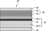
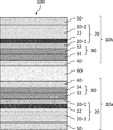
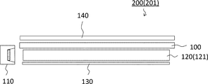
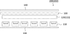
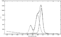
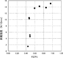
- FIG. 2 is a schematic cross-sectional view schematically illustrating an embodiment of the wavelength conversion sheet of the present disclosure. It is sectional drawing which shows one Embodiment of the backlight of this disclosure. It is sectional drawing which shows the other embodiment of the backlight of this disclosure. It is the C1s spectrum and the peak separation result on the surface of the primer layer of Example 1. It is a graph which shows the relationship between P2 / P1 and adhesion for each Example and comparative example.
- the barrier film is a barrier film for a wavelength conversion sheet including a phosphor layer containing a phosphor.
- the barrier film is provided to prevent oxygen and water vapor from reaching the phosphor layer from the external environment and deteriorating the phosphor layer.
- the barrier film of the present disclosure has a barrier layer and a primer layer, the primer layer contains a cured product of a polyurethane resin composition, and the surface of the primer layer opposite to the barrier layer is X.
- FIG. 1 is a schematic cross-sectional view schematically illustrating an embodiment of the barrier film of the present disclosure.
- the barrier film 10 has a barrier layer 30 and a primer layer 40 on the base material layer 20.
- the barrier layer 30 is formed on the base material layer 20 and the primer layer 40 is formed on the surface of the barrier layer 30 opposite to the base material layer 20.
- the diffusion layer 50 may be provided on the surface of the base material layer 20 opposite to the surface on which the barrier layer 30 is formed.
- the barrier film preferably has a high total light transmittance measured based on JIS K 7361-1: 1997 in order to efficiently convert the light from the light source when used as a wavelength conversion sheet.
- the barrier film preferably has a total light transmittance of 85% or more, more preferably 90% or more, as measured based on JIS K 7361-1: 1997.
- the barrier film preferably has an oxygen permeability value of 5 cc / m 2 ⁇ day ⁇ atm or less (23 ° C., 90% RH) according to JIS K 7126-2: 2006. Further, it is preferable that the value of the water vapor transmission rate by the JIS K 7129: 2008 B method is 5 g / m 2 ⁇ day ⁇ atm or less (40 ° C., 90% RH).
- the oxygen permeability can be measured by, for example, the oxygen permeability measuring device "OX-TRAN" manufactured by MOCON (Mocon method). Further, the water vapor barrier property can be measured by, for example, the water vapor permeability measuring device "PERMATRAN” manufactured by MOCON.
- each layer of the barrier film will be described.
- the base material layer mainly serves as a support for the barrier layer and the primer layer.
- the base material layer is preferably one having high light transmittance.
- the base material layer preferably has a total light transmittance of 85% or more, more preferably 90% or more, in accordance with JIS K 7361-1: 1997.
- the material of the base material layer is not particularly limited as long as it is a resin film that does not impair the function of the wavelength conversion sheet.
- the base material layer for example, polyimide (PI), polyethylene naphthalate (PEN), polyethylene terephthalate (PET), polyethylene butylate (PBT), acrylate polyarylate, polysulfone, polyethersulfone, polyetherimide, fluororesin , Resins such as liquid crystal polymers can be mentioned. From the viewpoint of transparency and heat resistance, it is preferable to use polyethylene naphthalate (PEN) or polyethylene terephthalate (PET) as the base material layer.
- PEN polyethylene naphthalate
- PET polyethylene terephthalate
- the base material layer may be a resin film composed of a single layer, or a plurality of resin films may be bonded via an adhesive layer.
- the first base material 20-1 and the second base material 20-2 are adhered to each other via the adhesive layer 22.
- the first base material 20-1 serves as a support for forming the barrier layer 30 and the primer layer 40.
- the second base material 20-2 plays a role of increasing the thickness of the entire base material layer 20 and imparting rigidity to the barrier film 10.
- the thickness of the base material layer is not particularly limited, but is preferably 8 ⁇ m or more and 200 ⁇ m or less, and more preferably 8 ⁇ m or more and 150 ⁇ m or less.
- the thickness of the base material layer is preferably 8 ⁇ m or more and 125 ⁇ m or less.
- the thickness of the first base material serving as a support for the barrier layer and the primer layer is preferably 8 ⁇ m or more and 50 ⁇ m or less, and preferably 8 ⁇ m or more and 25 ⁇ m or less. More preferably, it is 8 ⁇ m or more and 20 ⁇ m or less.
- the thickness of the second base material is preferably 8 ⁇ m or more and 150 ⁇ m or less, and more preferably 8 ⁇ m or more and 100 ⁇ m or less. With the above thickness, it is possible to impart appropriate rigidity to the barrier film. Further, when the barrier film is manufactured by the winding method, the handleability is improved.
- the adhesive constituting the adhesive layer 22 is not particularly limited as long as it satisfies the good adhesiveness between the base material layers and the optical performance required for the barrier film and the wavelength conversion sheet.
- the adhesive comprises a polyvinyl acetate adhesive, a homopolymer such as ethyl, butyl, or 2-ethylhexyl ester of acrylic acid, or a copolymer of these with methyl methacrylate, acrylonitrile, styrene, or the like.
- the composition system of the adhesive constituting the adhesive layer may be any composition form such as an aqueous type, a solution type, an emulsion type, and a dispersed type, and the properties thereof are film-like, sheet-like, powder-like, and solid. Any form such as a shape may be used, and the bonding mechanism may be any form such as a chemical reaction type, a solvent volatilization type, a heat melting type, and a thermal pressure type.
- the adhesive layer may be formed by, for example, a thermosetting resin or a resin in which a thermoplastic resin contains a cross-linking agent or the like.
- a thermoplastic resin such as EVA, ionomer, polyvinyl butyral (PVB), or polyethylene-based resin may be extruded between the base materials by extrusion lamination to form an adhesive layer.
- the surface of the base material layer on the side where the barrier layer is provided may be subjected to a desired surface treatment in advance in order to improve the adhesion with the barrier layer.
- a desired surface treatment examples include corona discharge treatment, ozone treatment, low-temperature plasma treatment using oxygen gas or nitrogen gas, glow discharge treatment, and oxidation treatment using chemicals or the like.
- a base layer such as an anchor coating agent layer or an adhesive layer may be formed in advance.
- the base layer for example, a polyester resin, a polyamide resin, a polyurethane resin, an epoxy resin, a phenol resin, a (meth) acrylic resin, a polyvinyl acetate resin, a polyolefin resin such as polyethylene or polypropylene, or a polyolefin resin thereof.
- a resin composition containing a copolymer or a modified resin, a cellulose-based resin, or the like as the main component of the vehicle can be used.
- the barrier layer is a layer that imparts gas barrier properties to the barrier film.
- the barrier layer 30 is formed by laminating an inorganic oxide thin film layer 32 and an organic coating layer 34 in order from the base material layer 20 side.
- the barrier layer is not limited to the laminated structure shown in FIG. 1, and the organic coating layer or the inorganic oxide thin film layer may be formed of a single layer, and the inorganic oxide thin film layer and the organic coating layer alternate. It may be a layer in which two or more layers are laminated. Further, the inorganic oxide thin film layer and the organic coating layer may be a single layer or a plurality of laminated layers, respectively.
- the inorganic oxide thin film layer can be exemplified as a layer composed of aluminum oxide, silicon oxide, magnesium oxide or a mixture thereof. From the viewpoint of sufficient gas barrier property, transparency, productivity and the like, the inorganic oxide thin film layer is preferably a thin film layer containing aluminum oxide or silicon oxide as a main component.
- Examples of the method of forming the inorganic oxide thin film layer include a method of forming by depositing an inorganic oxide.
- Examples of the method for forming the vapor deposition film include a physical vapor deposition method (Physical Vapor Deposition method, PVD method) such as a vacuum vapor deposition method, a sputtering method, and an ion plating method, or a plasma chemical vapor deposition method and thermochemistry.
- Examples thereof include a chemical vapor deposition method (Chemical Vapor Deposition method, CVD method) such as a vapor phase growth method and a photochemical vapor deposition method.
- the thickness of the inorganic oxide thin film layer is not particularly limited, but is preferably 5 nm or more and 500 nm or less. When the thickness of the inorganic oxide thin film layer is 5 nm or more, the inorganic oxide thin film layer becomes uniform, and sufficient gas barrier properties can be imparted to the barrier film. Considering the gas barrier property, the inorganic oxide thin film layer is more preferably 8 nm or more, and further preferably 10 nm or more. Further, when the thickness of the inorganic oxide thin film layer is 500 nm or less, sufficient flexibility can be imparted to the inorganic oxide thin film layer, and scratches and cracks occur in each inorganic oxide thin film layer. It can be reduced.
- the inorganic oxide thin film layer is more preferably 100 nm or less, further preferably 50 nm or less, and particularly preferably 20 nm or less in consideration of transparency, productivity and the like.
- each inorganic oxide thin film layer has the above thickness range.
- the organic coating layer is a layer that prevents various secondary damages in the subsequent process and imparts high gas barrier properties to the barrier film. Further, by locating the inorganic oxide thin film layer between the base material layer and the organic coating layer, it is possible to reduce the occurrence of scratches and cracks in the inorganic oxide thin film layer. Further, by providing the organic coating layer in contact with the primer layer, the adhesion between the primer layer and the barrier layer of the present disclosure can be improved.
- the organic coating layer uses, for example, a gas barrier composition containing, for example, a water-soluble polymer and an aqueous solution or a water / alcohol mixed solution containing at least one of one or more metal alkoxides and hydrolysates, or tin chloride as a coating liquid. , Is formed by applying the coating liquid.
- the organic coating layer preferably contains at least one selected from the group consisting of a hydroxyl group-containing polymer compound, a metal alkoxide, a metal alkoxide hydrolyzate, and a metal alkoxide polymer as a component.
- Examples of the water-soluble polymer used for the organic coating layer include polyvinyl alcohol, polyvinylpyrrolidone, and an ethylene / vinyl alcohol copolymer.
- polyvinyl alcohol and / or an ethylene / vinyl alcohol copolymer when polyvinyl alcohol and / or an ethylene / vinyl alcohol copolymer is used, excellent gas barrier properties can be obtained.
- the content of the polyvinyl alcohol-based resin and / or the ethylene / vinyl alcohol copolymer is preferably in the range of 5 parts by mass or more and 500 parts by mass or less with respect to 100 parts by mass of the total amount of the above alkoxides. It is more preferably in the range of 20 parts by mass or more and 200 parts by mass or less.
- a silane coupling agent or the like can also be added to the gas barrier composition.
- the silane coupling agent known organic reactive group-containing organoalkoxysilanes can be used.
- an organoalkoxysilane having an epoxy group is particularly preferable, and it may be, for example, ⁇ -glycidoxypropyltrimethoxysilane, ⁇ -glycidoxypropylmethyldiethoxysilane, or ⁇ - ( 3,4-Epoxycyclohexyl) ethyltrimethoxysilane and the like can be used.
- the above-mentioned silane coupling agent may be used alone or in admixture of two or more.
- the amount of the silane coupling agent used as described above is preferably 1 part by mass or more and 20 parts by mass or less with respect to 100 parts by mass of the above alkoxysilane.
- the thickness of the organic coating layer is not particularly limited, but is preferably 100 nm or more and 500 nm or less. When the thickness of the organic coating layer is 100 nm or more, sufficient gas barrier properties can be imparted to the barrier film. Considering the gas barrier property, the organic coating layer is more preferably 120 nm or more, and further preferably 150 nm or more. Further, when the thickness of the organic coating layer is 500 nm or less, sufficient transparency can be ensured. Considering transparency, productivity and the like, the organic coating layer is more preferably 300 nm or less, and further preferably 200 nm or less. When a plurality of organic coating layers are provided, it is preferable that each organic coating layer has the above thickness range.
- the total light transmittance measured based on JIS K 7361-1: 1997 is high.
- the total light transmittance measured based on JIS K 7361-1: 1997 when a barrier layer is formed on a PET film (thickness: 12 ⁇ m) is preferably 85% or more, and 90% or more. More preferably.
- the total light transmittance is in the above range, the light of the light source can be efficiently converted when the barrier film is used as the wavelength conversion sheet.
- the value of oxygen permeability according to JIS K 7129-2: 2006 when the barrier layer is formed on the PET film (thickness: 12 ⁇ m) is 5 cc / m 2 ⁇ day ⁇ atm or less (23 ° C., 90). % RH), and more preferably 2 cc / m 2 ⁇ day ⁇ atm or less.
- the value of the water vapor transmission rate by the JIS K 7129: 2008 B method when the barrier layer was formed on the PET film (thickness: 12 ⁇ m) was 5 g / m 2 ⁇ day ⁇ atm or less (40 ° C., 90% RH). Is preferable, and it is more preferably 2 g / m 2 ⁇ day ⁇ atm or less.
- Primer layer When the primer layer is used as a wavelength conversion sheet, it secures good adhesion to the phosphor layer, prevents peeling of the barrier film and the phosphor layer even in a high temperature and high humidity environment, and deteriorates the phosphor layer. Plays a role in preventing.
- the primer layer contains a cured product of a polyurethane-based resin composition.
- the fact that the primer layer contains a polyurethane resin composition means that X-ray photoelectron spectroscopy (XPS), infrared spectroscopy (IR), nuclear magnetic resonance (NMR), gas chromatography-mass spectrometry (GCMS), etc. It can be confirmed by detecting the CN bond.
- XPS X-ray photoelectron spectroscopy
- IR infrared spectroscopy
- NMR nuclear magnetic resonance
- GCMS gas chromatography-mass spectrometry
- the surface of the primer layer opposite to the barrier layer is the area of the peak derived from the CC bond in the C1s spectrum obtained by X-ray photoelectron spectroscopy (hereinafter, may be simply referred to as “XPS”).
- XPS X-ray photoelectron spectroscopy
- the content of CN bonds on the surface of the primer layer calculated using the N1s spectrum is 1.1% or more. While it is about 2.3%, the content of CO bonds calculated using the C1s spectrum is 18.8 to 31.1%. That is, since the content of CN bond in the primer layer is very small and negligible as compared with the content of CO bond, the influence of the peak derived from CN bond can be ignored in the C1s spectrum. can. That is, in the C1s spectrum, the peak appearing in the vicinity of 285 to 287 eV can be considered to be derived from the CO bond.
- the phosphor layer and the primer layer of the barrier film are brought into contact with each other and laminated to form a wavelength conversion sheet, and the adhesion between the phosphor layer and the barrier film is formed. Is dramatically improved. The reason for this is not clear, but it is considered that the chemical bond state on the surface of the primer layer is involved.
- the CO-binding signal detected by XPS analysis is mainly derived from the terminal C-OH group. That is, a large value of P2 / P1 means that there are many OH groups on the surface of the primer layer.
- the OH groups on the surface of the primer layer are considered to be bonded to the functional groups (for example, NCO groups) of the sealing resin of the phosphor layer. Therefore, the fact that P2 / P1 is 0.55 or more and the surface is a primer layer with many CO bonds (that is, the surface is a primer layer with many OH groups) is a barrier film and a phosphor layer. It is considered that this is one of the factors that improve the adhesion of the film.
- P2 / P1 is preferably 0.65 or more, more preferably 0.80 or more, and further preferably 0.90 or more. If P2 / P1 is too large, the adhesion between the barrier film and the phosphor layer may decrease.
- P2 / P1 is preferably 1.0 or less.
- the ratio of P3 to the total of P1, P2, and P3 is preferably 0.05 or more, preferably 0.08 or more. Is more preferable.
- the ratio of P3 is preferably 0.40 or less, and more preferably 0.30 or less.
- the polyurethane resin composition contains a one-component or two-component polyurethane resin composition obtained by reacting a polyfunctional isocyanate with a hydroxyl group-containing compound. Only one type of the polyfunctional isocyanate and the hydroxyl group-containing compound may be used, or a plurality of types may be used.
- the polyfunctional isocyanate include aromatic polyisocyanates such as tolylene diisocyanate, diphenylmethane diisocyanate, xylylene diisocyanate, and polymethylene polyphenylene polyisocyanate, and aliphatic polyisocyanates such as hexamethylene diisocyanate and isophorone diisocyanate. Can be mentioned.
- Examples of the hydroxyl group-containing compound include polyether polyols, polyester polyols, polyester polyurethane polyols, and polyacrylate polyols.
- a polyester polyurethane polyol is particularly preferable from the viewpoint of adhesion to the phosphor layer and durability.
- the polyester polyurethane polyol can be produced, for example, by the methods described in JP-A-2001-288408 and JP-A-2003-26996.
- the value of P2 / P1 can be adjusted by changing the components constituting the primer layer and the content thereof. Specifically, the higher the ratio of hydroxyl groups in the polyurethane resin composition, the larger P2 / P1 on the surface of the primer layer.
- the ratio of hydroxyl groups in the polyurethane resin composition can be adjusted by changing the hydroxyl value of the hydroxyl group-containing compound, the NCO / OH ratio in the polyurethane resin composition, the molecular weight of the polyurethane resin composition, and the like.
- the value of P2 / P1 can be adjusted to an appropriate range in which the adhesion is improved.
- the hydroxyl value of the hydroxyl group-containing compound is preferably 40 mgKOH / g or more, and more preferably 42 mgKOH / g or more.
- P2 / P1 can be easily set to 0.55 or more.
- the NCO / OH ratio in the polyurethane resin composition is preferably 1.1 or more, more preferably 1.2 or more.
- the NCO / OH ratio in the polyurethane resin composition is preferably 3.0 or less, more preferably 2.0 or less.
- P2 / P1 can be easily set to 0.55 or more.
- the molecular weight (weight average molecular weight) of the polyurethane resin composition is preferably 1,000 or more and 100,000 or less.
- the surface of the primer layer (contact surface with the phosphor layer described later) is subjected to corona discharge treatment, ozone treatment, low temperature plasma treatment using oxygen gas, nitrogen gas, or the like.
- P2 / P1 value may be adjusted by performing surface treatment such as glow discharge treatment and oxidation treatment using chemicals or the like.
- the polyurethane resin composition preferably contains 40% by mass or more, more preferably 70% by mass or more, in the total amount of the primer layer. By containing 40% by mass or more of the polyurethane resin composition, the adhesion between the primer layer and the phosphor layer can be improved.
- the primer layer may further contain a silane coupling agent.
- a silane coupling agent By including the silane coupling agent, the adhesion between the primer layer and the barrier layer (particularly the organic coating layer) can be improved.
- a silane coupling agent a functional group at one end of the molecule, usually a chloro, alkoxy, or acetoxy group, is hydrolyzed to form a silanol group (Si-OH).
- Si-OH silanol group
- the resin composition of the primer layer is modified by a covalent bond or the like to form a strong bond.
- the adhesion between the barrier layer and the primer layer, and the primer layer and the phosphor layer is improved by using an organic functional group such as vinyl, methacryloxy, amino-based, epoxy-based, or mercapto at the other end of the silane coupling agent. Can be enhanced.
- organically functional silane monomers having dual reactivity can be used, for example, ⁇ -chloropropyltrimethoxysilane, vinyltrichlorosilane, vinyltriethoxysilane, vinyl-tris ( ⁇ ).
- -Methoxyethoxy) silane ⁇ -methacryloxypropyltrimethoxysilane, ⁇ - (3,4-epoxycyclohexyl) ethyltrimethoxysilane, ⁇ -glycidoxypropyltrimethoxysilane, vinyltriacetoxysilane, ⁇ -mercaptopropyltri Methoxysilane, N- ⁇ (aminoethyl) - ⁇ -aminopropyltrimethoxysilane, N- ⁇ (aminoethyl) - ⁇ -aminopropylmethyldimethoxysilane, ⁇ -ureidopropyltriethoxysilane, bis ( ⁇ -hydroxyethyl)
- One or more of - ⁇ -aminopropyltriethoxysilane, an aqueous solution of ⁇ -aminopropyl silicate, and the like can be used.
- the above silane coupling agent is preferably contained in an amount of 1% by mass or more, more preferably 3% by mass or more, based on the total amount of the primer layer.
- the silane coupling agent is preferably contained in an amount of 30% by mass or less, preferably 20% by mass or less, based on the total amount of the primer layer. It is more preferable to contain it.
- the primer layer may further contain a filler.
- the filler has a role of adjusting the viscosity of the coating liquid for forming the primer layer and improving the coating suitability and the like.
- the filler for example, calcium carbonate, barium sulfate, alumina white, silica, talc, glass frit, resin powder and the like can be used.
- the primer layer may further contain additives such as stabilizers, cross-linking agents, lubricants, ultraviolet absorbers, and the like, if necessary.
- the thickness of the primer layer is not particularly limited, but is preferably 0.05 ⁇ m or more, and more preferably 0.1 ⁇ m or more. Further, from the viewpoint of handleability, productivity and the like, the thickness of the primer layer is preferably 10 ⁇ m or less, and more preferably 3 ⁇ m or less.
- the primer layer according to the present embodiment preferably has a high total light transmittance measured based on JIS K 7361-1: 1997 in order to efficiently convert the light from the light source.
- the primer layer according to the present embodiment has a total light transmittance of 85% or more measured based on JIS K 7361-1: 1997 when the primer layer is formed on a PET film (film thickness: 12 ⁇ m). It is preferably 90% or more, and more preferably 90% or more.
- the diffusion layer is a layer provided for the purpose of reducing the anisotropy of the light emission angle distribution and preventing sticking, and is a layer arbitrarily provided in the present disclosure.
- the diffusion layer contains a binder resin and a filler.
- the filler itself is embedded in the binder resin, and at least a part of the filler is exposed from the binder resin to the surface side of the layer to give an uneven shape to the surface of the diffusion layer, so that the light emission angle distribution is anisotropic. The effect of reducing the sex can be obtained.
- the surface of the diffusion layer has an uneven shape, it has a role of preventing sticking even if the barrier films or the wavelength conversion sheets come into contact with each other in the manufacturing process of the barrier film or the wavelength conversion sheet.
- the barrier film or the wavelength conversion sheet can be easily handled and surface scratches can be suppressed.
- it when used as a display device, it also has a role of preventing the light guide plate or diffuser plate from sticking to the wavelength conversion sheet, and suppresses the occurrence of scratches due to rubbing between the light guide plate or diffuser plate and the wavelength conversion sheet for display. It also has the effect of reducing the occurrence of poor appearance of the device.
- the binder resin of the diffusion layer is not particularly limited as long as it meets the specifications required for the barrier film and the wavelength conversion sheet.
- acrylic resin, epoxy resin, urethane resin, polyester resin, polyester acrylate resin, polyurethane acrylate resin, acrylic urethane resin, epoxy acrylate resin and the like can be used.
- the binder resin is preferably an acrylic resin.
- the filler is preferably a resin filler from the viewpoint of optical performance required for the barrier film and the wavelength conversion sheet.
- the resin used for the filler include acrylic resin and polystyrene resin. From the viewpoint of improving the scratch resistance of the diffusion layer, an acrylic resin filler is particularly preferable.
- the acrylic resin here is an ethylenically unsaturated monomer having at least one carboxyl group or carboxylic acid ester group selected from the group consisting of methacrylic acid, acrylic acid, methacrylic acid ester, and acrylic acid ester. It is a polymer contained as a monomer component.
- the difference in refractive index between the refractive index of the filler and the refractive index of the resin binder is preferably 0.5 or less, more preferably 0.3 or less, and further preferably 0.1 or less.
- the average particle size of the filler is preferably 1 ⁇ m or more and 50 ⁇ m or less, and more preferably 1.5 ⁇ m or more and 10 ⁇ m or less.
- the average particle size of the filler is 1 ⁇ m or more, at least a part of the filler is exposed more from the surface of the diffusion layer, which gives appropriate light diffusivity and suppresses sticking more effectively. be able to.
- the average particle size of the filler is 50 ⁇ m or less, the filler is less likely to be detached from the diffusion layer, and it is possible to suppress deterioration of the function of the diffusion layer and damage caused by the removed filler.
- the average particle size can be measured by, for example, a dynamic light scattering method, a laser diffraction scattering method, or SEM or TEM observation.
- the average particle size may be, for example, the particle size obtained as the value of D50 in the particle size distribution measurement based on JIS Z 8820 and JIS Z 8822.
- the content of the filler is preferably 5% by mass or more and 50% by mass or less, and more preferably 10% by mass or more and 40% by mass or less with respect to the total amount of the diffusion layer.
- it is 5% by mass or more, it is possible to provide appropriate light diffusivity and effectively prevent sticking.
- it is 50% by mass or less, it becomes easy to satisfy the optical characteristics required for the barrier film and the wavelength conversion sheet, and the film forming property of the diffusion layer can be improved.
- the diffusion layer may optionally contain additives such as stabilizers, curing agents, cross-linking agents, lubricants, ultraviolet absorbers, and the like, if necessary.
- the thickness of the diffusion layer is not particularly limited, and can be appropriately set according to the average particle size of the filler, the specifications required for the barrier film and the wavelength conversion sheet, and the like.
- the thickness of the diffusion layer is preferably 1.0 ⁇ m or more and 50.0 ⁇ m or less, and more preferably 1.5 ⁇ m or more and 10.0 ⁇ m or less.
- the thickness of the diffusion layer means the thickness of the resin portion other than the filler in the diffusion layer, and does not include the portion of the filler cueed on the resin.
- the thickness of the anti-diffusion layer can be measured, for example, by observing the cross section with a scanning electron microscope or the like.
- the method for producing a barrier film of the present disclosure includes at least (1) a barrier layer forming step and (2) a primer layer forming step.
- a Barrier layer forming step An organic coating layer and / or an inorganic oxide thin film layer is laminated as a barrier layer on one surface of a base material layer (or a first base material).
- the organic coating layer and the inorganic oxide thin film layer are used as the barrier layer, the inorganic oxide thin film layer is first formed on the base material layer (or the first base material), and then on the inorganic oxide thin film layer. Form an organic coating layer.
- the surface of the base material layer (or the first base material) on which the barrier layer is formed may be subjected to the above-mentioned surface treatment in advance, or the base layer may be formed.
- the inorganic oxide thin film layer can be formed by depositing an inorganic oxide.
- the method for depositing an inorganic oxide is a physical vapor deposition method (Physical Vapor Deposition method, PVD method) such as a vacuum vapor deposition method, a sputtering method, and an ion plating method, or a plasma chemical vapor deposition method or a thermochemical vapor deposition method. Examples thereof include a chemical vapor deposition method (Chemical Vapor Deposition method, CVD method) such as a phase growth method and a photochemical vapor deposition method.
- the organic coating layer can be formed by applying a coating agent containing the above gas barrier composition and curing it by heating.
- the coating agent is adjusted by adding a solvent or the like to the gas barrier composition so that the desired gas barrier property, thickness, viscosity and the like can be obtained.
- Examples of the method of applying the coating agent include roll coating, gravure coating, knife coating, dip coating, spray coating, and other coating methods.
- Primer layer forming step A primer layer is formed on the barrier layer.
- the primer layer can be formed by applying a coating agent containing the polyurethane resin composition and curing the primer layer by heating.
- the coating agent is adjusted by adding a solvent or the like to the gas barrier composition so that a desired P2 / P1 ratio, P3 area ratio, thickness, viscosity and the like can be obtained.
- the content of the polyfunctional isocyanate in the polyurethane resin composition is blended so that the NCO / OH ratio is 1.0 to 3.0.
- Examples of the method of applying the coating agent include roll coating, gravure coating, knife coating, dip coating, spray coating, and other coating methods.
- the method for producing a barrier film of the present disclosure includes (2) a primer layer forming step and then (3) an adhesion step. Have. (3) Adhesive Step
- the surface of the first base material opposite to the barrier layer and the second base material are laminated via the adhesive layer.
- the above-mentioned adhesive is applied to the surface of the first base material, the second base material is overlapped, and the adhesive layer is cured.
- the second base material is overlapped and the coating agent is cross-linked by heat or the like.
- the method of applying the adhesive or coating agent can be applied by a roll coating, a gravure coating, a knife coating, a depth coating, a spray coating, another coating method, a printing method or the like.
- the melted thermoplastic resin may be flowed between the first base material and the second base material by extrusion laminating, and then cooled to form an adhesive layer.
- the diffusion layer is formed in advance on the base material layer or the second base material.
- a coating agent containing a resin, a filler, a solvent, etc. may be applied to the surface of the base material layer or the surface of the second base material opposite to the surface on which the barrier layer is provided, and cured to form the surface.
- Examples of the method of applying the coating agent include roll coating, gravure coating, knife coating, dip coating, spray coating, and other coating methods.
- the barrier film of the present disclosure can be used, for example, as a barrier film for a wavelength conversion sheet of a surface light source.
- the surface light source include a backlight light source of a liquid crystal display device, a backlight light source of an inspection device, and the like. That is, the barrier film of the present disclosure can be used for "a barrier film for a wavelength conversion sheet for a backlight light source of a liquid crystal display device", "a barrier film for a wavelength conversion sheet for a backlight light source of an inspection device", and the like. Further, the barrier film of the present disclosure can also be used as a "barrier film for a wavelength conversion sheet for horticulture”.
- Examples of the horticultural wavelength conversion sheet include a sheet having a function of converting ultraviolet rays into a wavelength suitable for plant growth.
- Examples of wavelengths suitable for plant growth include wavelengths suitable for photosynthesis.
- the horticultural wavelength conversion sheet can be installed, for example, on the ceiling of a horticultural facility such as a vinyl house or a glass room.
- FIG. 2 is a schematic cross-sectional view schematically illustrating an embodiment of the wavelength conversion sheet of the present disclosure.
- the wavelength conversion sheet 100 of FIG. 2 includes the barrier films 10 (10a, 10b) described above on both surfaces of the phosphor layer 60.
- the barrier film 10 of the present disclosure may be provided on at least one surface side of the phosphor layer 60. That is, the barrier film 10 (10a) of the present disclosure is provided on one surface side of the phosphor layer 60, and another barrier film other than the barrier film of the present disclosure described above is provided on the other surface side of the phosphor layer 60. You may be.
- the phosphor layer is a layer for adjusting the emission wavelength of light emitted from a backlight source.
- the phosphor layer can be formed by laminating a sealing resin containing a phosphor. For example, it can be formed by applying a mixed solution containing a phosphor and a sealing resin to the surface of a base material layer and curing the mixture.
- the phosphor layer contains one or more types of phosphors composed of quantum dots.
- the quantum dots forming the phosphor are semiconductor particles of a predetermined size having a quantum confinement effect.
- a quantum dot absorbs light from an excitation source and reaches an energy excited state, it emits energy corresponding to the energy band gap of the quantum dot.
- the energy bandgap can be adjusted, and energy in various levels of wavelength bands can be obtained.
- quantum dots can generate strong fluorescence in a narrow wavelength band. Therefore, since the display device can be illuminated with the light of the three primary colors having excellent color purity, the display device can be made to have excellent color reproducibility.
- the quantum dots preferably include quantum dots that emit secondary light having a wavelength corresponding to red, quantum dots that emit secondary light having a wavelength corresponding to green, and combinations thereof.
- the quantum dots may include quantum dots other than quantum dots that emit secondary light having a wavelength corresponding to red and quantum dots that emit secondary light having a wavelength corresponding to green.
- the core of the quantum dot is a nanometer-sized fine particle of a semiconductor, and is not particularly limited as long as it is a material that produces a quantum confinement effect (quantum size effect).
- the quantum dots include semiconductor fine particles whose emission color is regulated by their own particle size and semiconductor fine particles having a dopant.
- semiconductor compounds such as group IV semiconductors such as Si, Ge and Pb, or semiconductor crystals containing semiconductors can be exemplified. Further, a semiconductor crystal containing a semiconductor compound containing three or more elements such as InGaP can also be used. Further, as the quantum dot composed of semiconductor fine particles having a dopant, a semiconductor crystal formed by doping the above semiconductor compound with a cation of a rare earth metal such as Eu 3+ , Tb 3+ , Ag + , or Cu + or a cation of a transition metal. It can also be used.
- Semiconductor crystals such as CdS, CdSe, CdTe, InP, and InGaP are used as the core material of quantum dots from the viewpoints of ease of fabrication, controllability of particle size that can obtain light emission in the visible range, and fluorescence quantum yield. Is preferable.
- the quantum dot may be composed of one kind of semiconductor compound or may be made of two or more kinds of semiconductor compounds.
- the quantum dot may have a structure (core-shell structure) in which the core as a light emitting portion is covered with a protective layer (shell).
- the semiconductor that constitutes the shell is a material with a bandgap higher than that of the semiconductor compound that forms the core so that excitons are confined in the core. Can be enhanced.
- Examples of the core-shell structure (core / shell) having such a bandgap magnitude relationship include CdSe / ZnS, CdSe / ZnSe, CdSe / CdS, CdTe / CdS, InP / ZnS, Gap / ZnS, Si / ZnS, and the like.
- InN / GaN, InP / CdSSe, InP / ZnSeTe, InGaP / ZnSe, InGaP / ZnS, Si / AlP, InP / ZnSTe, InGaP / ZnSTe, InGaP / ZnSse and the like can be mentioned.
- the size of the quantum dots may be appropriately controlled by the material constituting the quantum dots so that light having a desired wavelength can be obtained.
- the energy band gap of quantum dots increases as the particle size decreases. That is, as the crystal size becomes smaller, the emission of the quantum dots shifts to the blue side, that is, to the high energy side.
- the particle size (diameter) of the quantum dots is preferably in the range of 0.5 nm to 20 nm, and particularly preferably in the range of 1 nm to 10 nm. The narrower the size distribution of the quantum dots, the clearer the emission color can be obtained.
- the shape of the quantum dot is not particularly limited, and may be, for example, spherical, rod-shaped, disk-shaped, or other shape. When the particle dots are not spherical, the particle size of the quantum dots can be a true spherical value having the same volume.
- the quantum dots may be coated with a resin.
- the content of quantum dots is appropriately adjusted according to the thickness of the phosphor layer, the recycling rate of light in the backlight, the target color, and the like. If the thickness of the phosphor layer is within the range described later, the content of the quantum dots is about 0.01 to 1.0 parts by mass with respect to 100 parts by mass of the sealing resin of the phosphor layer.
- the sealing resin for the phosphor layer examples include a thermoplastic resin, a cured product of a thermosetting resin composition, and a cured product of an ionizing radiation curable resin composition.
- a cured product of the thermosetting resin composition and a cured product of the ionizing radiation curable resin composition are preferable, and a cured product of the ionizing radiation curable resin composition is more preferable from the viewpoint of durability.
- thermoplastic resin composition is a composition obtained by adding a cross-linking agent or the like to the thermoplastic resin.
- thermoplastic resin examples include EVA, ionomer, polyvinyl butyral (PVB), and polyethylene-based resin. These may be used alone, or one or more may be mixed and used.
- the thermosetting resin composition is a composition containing at least a thermosetting resin, and is a resin composition that is cured by heating.
- the thermosetting resin include acrylic resin, urethane resin, phenol resin, urea melamine resin, epoxy resin, unsaturated polyester resin, and silicone resin. These may be used alone, or one or more may be mixed and used.
- a curing agent is added to these curable resins as needed.
- the ionizing radiation curable resin composition is a composition containing a compound having an ionizing radiation curable functional group (hereinafter, also referred to as "ionizing radiation curable compound").
- the ionizing radiation curable functional group examples include an ethylenically unsaturated group such as a (meth) acryloyl group, a vinyl group and an allyl group, an epoxy group and an oxetanyl group, and among them, an ethylenically unsaturated group is preferable. .. Further, among the ethylenically unsaturated bond groups, a (meth) acrylate group is preferable.
- the ionizing radiation curable compound having a (meth) acryloyl group will be referred to as a (meth) acrylate compound.
- the sealing resin preferably contains a cured product of a composition containing a (meth) acrylate-based compound.
- (meth) acrylate refers to methacrylate and acrylate.
- ionizing radiation means an electromagnetic wave or a charged particle beam having an energy quantum capable of polymerizing or cross-linking a molecule, and usually, an electromagnetic wave (UV) or an electron beam (EB) is used. Although it is used, other electromagnetic waves such as X-rays and ⁇ -rays, and charged particle rays such as ⁇ -rays and ion-rays can also be used.
- the ionizing radiation curable compound may be a monofunctional ionizing radiation curable compound having only one functional group, or a polyfunctional ionizing radiation curable compound having two or more functional groups. , These may be a mixture.
- a polyfunctional ionizing radiation curable compound is preferable, and a polyfunctional (meth) acrylate-based compound having two or more (meth) acryloyl groups is more preferable.
- the sealing resin preferably contains a cured product of a polyfunctional ionizing radiation curable compound, and more preferably contains a cured product of a polyfunctional (meth) acrylate-based compound.
- the polyfunctional (meth) acrylate-based compound may have an alkyleneoxy group.
- an alkyleneoxy group having 2 to 4 carbon atoms is preferable, an alkyleneoxy group having 2 or 3 carbon atoms is more preferable, and an alkyleneoxy group having 2 carbon atoms is further preferable.
- the polyfunctional (meth) acrylate-based compound having an alkyleneoxy group may be a polyfunctional (meth) acrylate-based compound having a polyalkyleneoxy group containing a plurality of alkyleneoxy groups.
- the number of alkyleneoxy groups in one molecule is preferably 2 to 30, more preferably 2 to 20. The number is more preferably 3 to 10, and even more preferably 3 to 5.
- the polyfunctional (meth) acrylate compound When the polyfunctional (meth) acrylate compound has an alkyleneoxy group, it preferably has a bisphenol structure. This tends to improve the heat resistance of the cured product.
- the bisphenol structure include a bisphenol A structure and a bisphenol F structure, and among them, the bisphenol A structure is preferable.
- the polyfunctional (meth) acrylate compounds having an alkyleneoxy group ethoxylated bisphenol A type di (meth) acrylate, propoxylated bisphenol A type di (meth) acrylate and propoxylated ethoxylated bisphenol A type di (meth).
- Acrylate is preferable, and ethoxylated bisphenol A type di (meth) acrylate is more preferable.
- the ionizing radiation curable compound may be a monomer, an oligomer, a polymer having a low molecular weight, or a mixture thereof.
- the ionizing radiation curable compound is an ultraviolet curable compound
- the ionizing radiation curable composition preferably contains an additive such as a photopolymerization initiator or a photopolymerization accelerator.
- Internally diffused particles may be contained in the phosphor layer.
- the internal diffusion particles either organic particles or inorganic particles can be used.
- the organic particles include particles composed of polymethylmethacrylate, acrylic-styrene copolymer, melamine resin, polycarbonate, polystyrene, polyvinyl chloride, benzoguanamine-melamine-formaldehyde condensate, silicone resin, fluororesin, polyester and the like. ..
- examples of the inorganic fine particles include fine particles made of silica, alumina, zirconia, titania and the like.
- the shape of the internally diffused particles include a spherical shape, a disk shape, a rugby ball shape, and an indeterminate shape.
- the internal diffusion particles may be hollow particles, porous particles or solid particles.
- the content of the internally diffused particles is preferably 1 part by mass or more and 40 parts by mass or less, and more preferably 3 parts by mass or more and 30 parts by mass or less with respect to 100 parts by mass of the sealing resin.
- the average particle size of the internally diffused particles is preferably 1 ⁇ m or more and 7 ⁇ m or less, and more preferably 1 ⁇ m or more and 3 ⁇ m or less.
- the thickness of the phosphor layer is preferably 10 ⁇ m or more and 200 ⁇ m or less, more preferably 20 ⁇ m or more and 150 ⁇ m or less, and further preferably 30 ⁇ m or more and 130 ⁇ m or less.
- Refractive index n Z of the phosphor layer is preferably 1.40 or more 1.55 or less, more preferably 1.43 or more and 1.52 or less is 1.46 to 1.50 Is even more preferable.
- Refractive index n Z of the phosphor layer is generally governed by the refractive index of the sealing resin. This is because the phosphor layer has a low content of quantum dots, and even if an internal diffusing agent is contained, the internal diffusing agent has a particle size larger than the wavelength of light and does not affect the refractive index of the layer. ..
- the wavelength conversion sheet of the present disclosure can be produced by using at least one barrier film produced by the above-mentioned production method.
- a method of manufacturing a wavelength conversion sheet having a structure in which a phosphor layer is sandwiched between the barrier films of the present disclosure will be given as an example.
- a mixed liquid (ink) containing a phosphor and a sealing resin is applied to the surface of the primer layer of the barrier film of the present disclosure.
- Examples of the method of applying the mixed liquid (ink) include roll coating, gravure coating, knife coating, dip coating, spray coating, and other coating methods.
- the phosphor layer is brought into contact with another primer layer of the barrier film of the present disclosure.
- the mixed liquid (ink) is cured by heat or the like to obtain a wavelength conversion sheet.
- the backlight of the present disclosure includes at least one light source that emits primary light, an optical plate that is arranged adjacent to the light source and for guiding or diffusing, and a wavelength that is arranged on the light emitting side of the optical plate.
- the wavelength conversion sheet is the wavelength conversion sheet of the present disclosure described above.
- the backlight 200 of the present disclosure either the edge light type backlight shown in FIG. 3 or the direct type backlight shown in FIG. 4 can be adopted.
- the optical plate 120 used in the edge light type backlight 201 of FIG. 3 is an optical member for guiding the primary light emitted by the light source 110, and is a so-called light guide plate 121.
- the light guide plate 121 has, for example, a substantially flat plate shape formed so that at least one surface is a light incident surface and one surface substantially orthogonal to the light incident surface is a light emitting surface.
- the light guide plate is mainly made of a matrix resin selected from highly transparent resins such as polymethylmethacrylate. If necessary, resin particles having a refractive index different from that of the matrix resin may be added to the light guide plate.
- Each surface of the light guide plate may have a complicated surface shape instead of a uniform flat surface, and may be provided with a dot pattern or the like.
- the optical plate 120 used for the direct type backlight 202 of FIG. 4 is an optical member (light diffusing material 122) having a light diffusing property for making the pattern of the light source 110 difficult to see.
- Examples of the light diffusing material 122 include a milky white resin plate having a thickness of about 1 to 3 mm.
- the edge light type and direct type backlights include a reflector, a light diffusing film, a prism sheet, a brightness increasing film (BEF), and a reflective type, depending on the purpose. It may include one or more members selected from a polarizing film (DBEF) and the like.
- the reflector is arranged on the side opposite to the light emitting surface side of the optical plate.
- the light diffusing film, the prism sheet, the brightness increasing film and the reflective polarizing film are arranged on the light emitting surface side of the optical plate.
- a backlight having an excellent balance of front brightness, viewing angle, etc. shall be provided by having one or more members selected from a reflector, a light diffusing film, a prism sheet, a brightness increasing film, a reflective polarizing film, and the like. Can be done.
- the light source 110 is a light emitting body that emits primary light, and it is preferable to use a light emitting body that emits primary light having a wavelength corresponding to blue.
- the primary light having a wavelength corresponding to blue preferably has a peak wavelength in the range of 380 to 480 nm.
- the peak wavelength is more preferably 450 nm ⁇ 7 nm, more preferably 450 nm ⁇ 5 nm, more preferably 450 nm ⁇ 3 nm, and even more preferably 450 nm ⁇ 1 nm.
- the light source 110 is preferably an LED light source, and more preferably a blue monochromatic LED light source, from the viewpoint that the device for installing the backlight can be simplified and miniaturized.
- a red phosphor may be coated on a blue monochromatic LED light source to provide a blue and red light source.
- the number of light sources 110 is at least one, and it is preferable that there are a plurality of light sources 110 from the viewpoint of emitting sufficient primary light.
- Display device Examples of the display device include a liquid crystal display device.
- the liquid crystal display device includes a backlight and a liquid crystal panel.
- the backlight is the backlight of the present disclosure described above.
- the liquid crystal panel is not particularly limited, and a general-purpose liquid crystal panel can be used as the liquid crystal panel of the liquid crystal display device.
- a liquid crystal panel having a general structure in which the upper and lower sides of the liquid crystal layer are sandwiched between glass plates specifically, display methods such as TN, STN, VA, IPS, and OCB can be used.
- the liquid crystal display device further includes a polarizing plate, a color filter, and the like.
- polarizing plate a polarizing plate
- color filter a color filter
- General-purpose polarizing plates and color filters can be used.
- the wavelength conversion sheet of the present disclosure has particularly excellent adhesion between the barrier film and the phosphor layer. Therefore, when the wavelength conversion sheet of the present disclosure is applied to a display device (liquid crystal display device), deterioration of the phosphor layer due to intrusion of water vapor or oxygen from the external environment can be effectively suppressed. As a result, the display device can be provided with a backlit light source having excellent environmental stability.
- the elements contained in the primer layer were identified from the X-ray photoelectron spectrum, and the spectral area for each element was multiplied by the relative sensitivity factor to calculate the total spectral area. Then, the content of CN bond to all chemical bond species was calculated from the ratio of the area of the CN bond peak of the N1s spectrum to the total spectrum area. The results are shown in Table 1.
- Adhesion A wavelength conversion sheet was cut out to a size of 25 mm ⁇ 150 mm to prepare a test piece.
- a desktop material tester STA-1150, manufactured by Takachiho Seiki Co., Ltd.
- STA-1150 manufactured by Takachiho Seiki Co., Ltd.
- a peeling test under the conditions of a tensile speed of 300 mm / min, a peeling direction of 180 °, and a chuck distance of 15 mm in a temperature environment of 23 ° C.
- the peel strength between the barrier film and the phosphor layer was measured for each test piece. The results are shown in Table 1.
- wetting Index A plurality of wet index standard solutions (manufactured by Pacific Chemical Co., Ltd., trade name "Tension Checker") having different surface tensions are applied onto the primer layers of Examples and Comparative Examples, respectively, and the liquid film is torn after about 3 seconds. Alternatively, the presence or absence of shrinkage of the entire liquid film was confirmed. Wetting index that could be applied on the primer layer without causing tearing or shrinkage of the liquid film The largest value among the surface tension values of the standard solution was defined as the wetting index of the primer layer. The results are shown in Table 1.
- sample 2-1 Preparation of barrier film ⁇ Example 1>
- an aluminum oxide thin film AlOx, target thickness: 8 nm
- a PET film thickness: 12 ⁇ m
- Solution A was prepared by mixing tetraethoxysilane with a mixed solution (pH 2.2) of water, isopropyl alcohol and 0.5N hydrochloric acid while cooling to 10 ° C.
- a solution B in which polyvinyl alcohol and isopropyl alcohol having a saponification value of 99% or more were mixed was prepared.
- Solution A and solution B were mixed to prepare a coating liquid for forming an organic coating layer (solid content: 5%).
- a coating liquid for forming an organic coating layer was applied on the inorganic oxide thin film layer by gravure printing and heat-treated at 180 ° C. for 60 seconds to form an organic coating layer having a thickness of 180 nm.
- the primer layer forming coating solution of the following formulation was adjusted so that the NCO / OH ratio was 1.4.
- ⁇ Polyurethane polyurethane polyol (hydroxyl value: 62 mgKOH / g, solid content 20%) 50 parts by mass ⁇ Silane coupling agent (3-glycidoxypropylmethyl dimethoxysilane) 1 part by mass ⁇ Silica filler (average particle size 5 ⁇ m) 8 parts by mass Part ⁇ Hardener (1,6-hexamethylene diisocyanate, solid content 35%) 1 part by mass ⁇ Solvent (MEK) 50 parts by mass
- a coating solution for forming a primer layer was applied onto the organic coating layer and dried at 80 ° C. for 60 seconds to form a primer layer having a thickness of 0.4 ⁇ m.
- Gravure a urethane adhesive (manufactured by Rock Paint Co., Ltd., trade name "RU-004, H-1") on the surface opposite to the surface on which the inorganic oxide thin film layer to the primer layer of the first base material is formed. It was applied by printing and dried to form an adhesive layer having a thickness of 4 ⁇ m.
- a PET film (thickness: 100 ⁇ m) was placed as a second base material on the adhesive layer side of the first base material, and the first base was placed under the conditions of nip pressure: 0.2 MPa and line speed: 50 m / min. The material and the second base material were bonded together to prepare the barrier film of Example 1.
- Example 2 The barrier film of Example 2 was prepared in the same process as in Example 1 except that the coating liquid for forming a primer layer of the following formulation was used so that the NCO / OH ratio was 1.5.
- -Polyurethane polyurethane polyol hydroxyl value: 42 mgKOH / g, solid content 20%
- mass-Silane coupling agent 3-glycidoxypropylmethyl dimethoxysilane
- mass-Silica filler average particle size 5 ⁇ m
- Example 3 The barrier film of Example 3 was prepared in the same process as in Example 1 except that the coating liquid for forming a primer layer of the following formulation was used so that the NCO / OH ratio was 1.3.
- -Polyurethane polyurethane polyol hydroxyl value: 50 mgKOH / g, solid content 20%
- mass-Silane coupling agent 3-glycidoxypropylmethyl dimethoxysilane
- mass-Silica filler average particle size 5 ⁇ m
- Example 4 The barrier film of Example 4 was prepared in the same process as in Example 1 except that the coating liquid for forming a primer layer of the following formulation was used so that the NCO / OH ratio was 1.2.
- -Polyurethane polyurethane polyol (hydroxyl value: 52 mgKOH / g, solid content 20%) 50 parts by mass-Silane coupling agent (3-glycidoxypropylmethyldimethoxysilane) 1 part by mass-Silica filler (average particle size 5 ⁇ m) 1 mass Part ⁇ Hardener (1,3-xylylene diisocyanate, solid content 35%) 5 parts by mass ⁇ Solvent (MEK) 50 parts by mass
- Comparative example 1 A barrier film of Comparative Example 1 was prepared in the same process as in Example 1 except that the coating liquid for forming a primer layer of the following formulation was used so that the NCO / OH ratio was 1.0.
- -Polyurethane polyurethane polyol hydroxyl value: 33 mgKOH / g, solid content 20%
- mass-Silane coupling agent 3-glycidoxypropylmethyldimethoxysilane
- mass-Silica filler average particle size 5 ⁇ m
- Comparative example 2 A barrier film of Comparative Example 2 was prepared in the same process as in Example 1 except that the coating liquid for forming a primer layer having the following formulation was used so that the NCO / OH ratio was 0.8.
- -Polyurethane polyurethane polyol hydroxyl value: 38 mgKOH / g, solid content 20%
- mass-Silane coupling agent 3-glycidoxypropylmethyl dimethoxysilane
- mass-Silica filler average particle size 5 ⁇ m
- Comparative example 3 A barrier film of Comparative Example 3 was prepared in the same process as in Example 1 except that the coating liquid for forming a primer layer having the following formulation was used so that the NCO / OH ratio was 0.7.
- -Polyurethane polyurethane polyol hydroxyl value: 29 mgKOH / g, solid content 20%
- mass-Silane coupling agent 3-glycidoxypropylmethyl dimethoxysilane
- mass-Silica filler average particle size 5 ⁇ m
- Comparative example 4 A barrier film of Comparative Example 4 was prepared in the same process as in Example 1 except that the coating liquid for forming a primer layer having the following formulation was used so that the NCO / OH ratio was 0.9.
- -Polyurethane polyurethane polyol hydroxyl value: 35 mgKOH / g, solid content 20%
- mass-Silane coupling agent 3-glycidoxypropylmethyl dimethoxysilane
- mass-Silica filler average particle size 5 ⁇ m
- Comparative Example 5 A barrier film of Comparative Example 5 was prepared in the same process as in Example 1 except that the coating liquid for forming a primer layer of the following formulation was used. No curing agent was added to the coating liquid of Comparative Example 5. That is, the NCO / OH ratio of Comparative Example 5 is 0. -Polyester polyurethane polyol (hydroxyl value: 32 mgKOH / g, solid content 20%) 50 parts by mass-Silane coupling agent (3-glycidoxypropylmethyldimethoxysilane) 1 part by mass-Silane filler (average particle size 5 ⁇ m) 1 mass Parts / solvent (MEK) 50 parts by mass
- Table 1 shows the coating amount of the primer layer forming coating liquid for Examples 1 to 4 and Comparative Examples 1 to 5.
- wavelength conversion sheet A phosphor (quantum dots with an average particle size of 3 to 5 nm) whose core is cadmium selenide (CdSe) and whose shell is zinc sulfide (ZnS) is used as a sealing resin (ionizing radiation curable urethane acrylate resin). ) was mixed so that the amount of the phosphor was 1 part by mass with respect to 100 parts by mass of the sealing resin to prepare a mixed solution (ink) for forming a phosphor layer.
- a mixed solution (ink) for forming a phosphor layer.
- the ink was applied onto the primer layers of the barrier films of Examples and Comparative Examples so as to have a thickness of 100 ⁇ m (after drying) to form a phosphor layer.
- a phosphor layer By laminating the barrier films of Examples and Comparative Examples (the same as the barrier films coated with the above inks) on the phosphor layer so that the primer layer is in contact with the phosphor layer, and UV-curing laminating. , Examples 1 to 4 and Comparative Examples 1 to 5 were prepared.
- FIG. 6 is a graph showing the relationship between P2 / P1 and adhesion for each Example and Comparative Example.
- the horizontal axis is P2 / P1
- the vertical axis is the peel strength at the interface between the primer layer and the phosphor layer. It can be read from FIG. 6 that the peel strength at the interface between the primer layer and the phosphor layer changes abruptly in the vicinity of 0.50 for P2 / P1.
- P2 / P1 was 0.55 or more
- the peel strength was 13 N / 25 mm or more, and the adhesion between the primer layer and the phosphor layer was good.
- the hydroxyl value of the examples was high, and therefore P2 / P1 was high and the adhesion was improved.
Landscapes
- Chemical & Material Sciences (AREA)
- Physics & Mathematics (AREA)
- Organic Chemistry (AREA)
- Chemical Kinetics & Catalysis (AREA)
- Polymers & Plastics (AREA)
- Medicinal Chemistry (AREA)
- Health & Medical Sciences (AREA)
- Nonlinear Science (AREA)
- Optics & Photonics (AREA)
- General Physics & Mathematics (AREA)
- Engineering & Computer Science (AREA)
- Materials Engineering (AREA)
- Crystallography & Structural Chemistry (AREA)
- Mathematical Physics (AREA)
- Inorganic Chemistry (AREA)
- Manufacturing & Machinery (AREA)
- Mechanical Engineering (AREA)
- Metallurgy (AREA)
- Life Sciences & Earth Sciences (AREA)
- Wood Science & Technology (AREA)
- Laminated Bodies (AREA)
- Optical Filters (AREA)
- Liquid Crystal (AREA)
- Planar Illumination Modules (AREA)
Abstract
Description
本開示は上記課題に鑑みなされたものであり、波長変換シートとしたときに蛍光体層との密着性により優れたバリアフィルム、該バリアフィルムを有する波長変換シート、並びに、該波長変換シートを備えるバックライト及び表示装置を提供することを目的とする。
[1]バリア層と、プライマー層とを有し、前記プライマー層は、ポリウレタン系樹脂組成物の硬化物を含有し、前記プライマー層の前記バリア層と反対側の面は、X線光電子分光法によって得られるC1sスペクトルにおけるC-C結合に由来するピークの面積をP1、前記C1sスペクトルにおけるC-O結合に由来するピークの面積をP2としたときに、P2/P1が0.55以上である、波長変換シート用のバリアフィルム。
[2]基材層上に前記バリア層が形成され、前記バリア層の前記基材層と反対側の面に前記プライマー層が形成される、[1]に記載のバリアフィルム。
[3]前記バリア層が、無機酸化物薄膜層と、有機被覆層とを含み、前記有機被覆層が前記プライマー層と接触する、[1]または[2]に記載のバリアフィルム。
[4]蛍光体を含む蛍光体層の少なくとも一方の表面側に、前記プライマー層と前記蛍光体層とが接触するように[1]~[3]のいずれかに記載のバリアフィルムが設けられる、波長変換シート。
[5]一次光を放出する少なくとも1つの光源と、前記光源に隣接して配置され、導光又は拡散のための光学板と、前記光学板の光出射側に配置された波長変換シートとを備えたバックライトであって、前記波長変換シートが[1]~[4]のいずれかに記載の波長変換シートであるバックライト。
[6]バックライト及び液晶パネルを備えた液晶表示装置であって、前記バックライトが請求項5に記載のバックライトである液晶表示装置。
バリアフィルムは、蛍光体を含む蛍光体層を備える波長変換シート用のバリアフィルムである。バリアフィルムは、酸素及び水蒸気が外部環境から蛍光体層に到達して、該蛍光体層が劣化することを防止するために設けられる。
本開示のバリアフィルムは、バリア層と、プライマー層とを有し、前記プライマー層は、ポリウレタン系樹脂組成物の硬化物を含有し、前記プライマー層の前記バリア層と反対側の面は、X線光電子分光法によって得られるC1sスペクトルにおけるC-C結合に由来するピークの面積をP1、前記C1sスペクトルにおけるC-O結合に由来するピークの面積をP2としたときに、P2/P1が0.55以上である。
以下、バリアフィルムの各層について説明する。
基材層は、主としてバリア層及びプライマー層の支持体としての役割を担う。基材層は、高い光透過性を有するものが好適である。具体的には、基材層は、JIS K 7361-1:1997に準拠する全光線透過率が85%以上であることが好ましく、90%以上であることがより好ましい。
尚、上記の接着剤に代えて、例えば、熱硬化性樹脂や、熱可塑性樹脂に架橋剤等を含有させた樹脂により接着層を形成しても良い。あるいは、EVA、アイオノマー、ポリビニルブチラール(PVB)、ポリエチレン系樹脂等の熱可塑性樹脂を、押し出しラミネートにより基材の間に押出し、接着層を形成しても良い。
下地層としては、例えば、ポリエステル系樹脂、ポリアミド系樹脂、ポリウレタン系樹脂、エポキシ系樹脂、フェノール系樹脂、(メタ)アクリル系樹脂、ポリ酢酸ビニル系樹脂、ポリエチレンあるいはポリプロピレン等のポリオレフィン系樹脂あるいはその共重合体ないし変性樹脂、セルロース系樹脂、その他等をビヒクルの主成分とする樹脂組成物を使用することができる。
バリア層は、バリアフィルムにガスバリア性を付与する層である。
図1に示す例では、バリア層30は、基材層20側から順に、無機酸化物薄膜層32及び有機被覆層34が積層されて構成される。なお、バリア層は図1の積層構成に限定されず、有機被覆層又は無機酸化物薄膜層が単層で形成されたものであっても良く、無機酸化物薄膜層と有機被覆層とが交互に2層以上積層されるような層であっても良い。また、無機酸化物薄膜層及び有機被覆層はそれぞれ、単層であっても良く複数層積層されたものであっても良い。
無機酸化物薄膜層は、酸化アルミニウム、酸化珪素、酸化マグネシウム又はこれらの混合物からなる層を例示することができる。十分なガスバリア性、透明性、生産性などの観点から、無機酸化物薄膜層は、酸化アルミニウム又は酸化珪素を主成分とする薄膜層であることが好ましい。
有機被覆層は、後工程での二次的な各種損傷を防止すると共に、バリアフィルムに高いガスバリア性を付与する層である。また、無機酸化物薄膜層が基材層と有機被覆層との間に位置することにより、無機酸化物薄膜層に傷や割れが発生することを軽減することができる。また、有機被覆層がプライマー層と接触して設けられることにより、本開示のプライマー層とバリア層の密着性を良好にすることができる。
プライマー層は、波長変換シートとしたときに蛍光体層との良好な密着性を確保して、高温高湿環境下においてもバリアフィルムと蛍光体層との剥離を防止し、蛍光体層の劣化を防止する役割を果たす。
なお、プライマー層はポリウレタン系樹脂組成物を含むため、C1sスペクトルにおいてC-N結合に由来するピークも観測され得る。しかし、C1sスペクトルでは、C-N結合の結合エネルギー(285.2~288.5eV)とC-O結合の結合エネルギー(286.0~286.8eV)とは近接している。本開示のプライマー層について、N1sスペクトルを用いて算出されるプライマー層表面のC-N結合の含有量(プライマー層を構成するすべての結合に対するC-N結合の割合)は、1.1%~2.3%程度であるのに対し、C1sスペクトルを用いて算出されるC-O結合の含有量は18.8~31.1%である。つまり、プライマー層中のC-N結合の含有量は、C-O結合の含有量に比べて非常に少なく無視できるため、C1sスペクトルではC-N結合に由来するピークの影響を無視することができる。すなわち、C1sスペクトルにおいて、285~287eV付近に表れるピークは、C-O結合由来であるとみなすことができる。
この理由は定かではないが、プライマー層表面の化学結合状態が関与していると考えられる。XPS分析で検出されるC-O結合のシグナルは、主として末端のC-OH基に由来する。つまり、P2/P1の値が大きいことは、プライマー層表面にOH基が多いことを意味する。波長変換シートを形成した際に、プライマー層表面のOH基は、蛍光体層の封止樹脂の官能基(例えば、NCO基など)と結合すると考えられる。このため、P2/P1が0.55以上と、表面のC-O結合が多いプライマー層であること(すなわち、表面のOH基が多いプライマー層であること)が、バリアフィルムと蛍光体層との密着性が向上させる一因であると考えられる。P2/P1は、0.65以上であることが好ましく、0.80以上であることがより好ましく、0.90以上であることが更に好ましい。なお、P2/P1が大きすぎると、バリアフィルムと蛍光体層との密着性が低下する場合がある。また、P2/P1が大きすぎると、プライマー層表面に水分が吸着しやすくなり、また、蛍光体層の封止樹脂の官能基との結合に寄与しないC-OH基が多く残存しやすくなる。吸着水分や残存C-OH基の影響で、バリアフィルムと蛍光体層との密着性が低下する虞や、プライマー層との界面近傍で蛍光体の劣化が進行しやすくなる虞がある。このため、P2/P1は、1.0以下であることが好ましい。
具体的に、多官能イソシアネートとしては、トリレンジイソシアネート、ジフェニルメタンジイソシアネート、キシリレンジイソシアネート、ポリメチレンポリフェニレンポリイソシアネート等の芳香族ポリイソシアネ-ト、あるいは、ヘキサメチレンジイソシアネート、イソホロンジイソシアネート等の脂肪族ポリイソシアネート等が挙げられる。
また、ヒドロキシル基含有化合物としては、ポリエーテルポリオール、ポリエステルポリオール、ポリエステルポリウレタンポリオール、ポリアクリレートポリオールなどが挙げられる。本開示においては、蛍光体層との密着性、及び、耐久性の観点から、ポリエステルポリウレタンポリオールが特に好ましい。ポリエステルポリウレタンポリオールは、例えば特開2001-288408号公報、特開2003-26996号公報に記載の方法により製造することができる。
ポリウレタン系樹脂組成物中の水酸基の比率は、ヒドロキシル基含有化合物の水酸基価、ポリウレタン系樹脂組成物中のNCO/OH比、ポリウレタン系樹脂組成物の分子量などを変えることにより調整することができる。特に、水酸基価を適切な範囲としながら、NCO/OH比を所定の範囲とすることにより、P2/P1の値を密着性が向上する適切な範囲に調整することができる。
ヒドロキシル基含有化合物の水酸基価は、40mgKOH/g以上であることが好ましく、42mgKOH/g以上であることがより好ましい。上記の水酸基価を有するヒドロキシル基含有化合物を用いることにより、P2/P1を0.55以上にしやすくすることができる。
ポリウレタン系樹脂組成物中のNCO/OH比は、1.1以上であることが好ましく、1.2以上であることがより好ましい。また、ポリウレタン系樹脂組成物中のNCO/OH比は、3.0以下であることが好ましく、2.0以下であることがより好ましい。NCO/OH比を上記範囲とすることにより、P2/P1を0.55以上としやすくすることができる。
ポリウレタン系樹脂組成物の製造に用いる多官能イソシアネート及びヒドロキシル基含有化合物の種類にもよるが、ポリウレタン系樹脂組成物の分子量が小さい程、相対的にポリウレタン系樹脂組成物中の水酸基の比率が高くなり、P2/P1を上記範囲としやすくなる。ポリウレタン系樹脂組成物の分子量(重量平均分子量)としては、1,000以上100,000以下であることが好ましい。
拡散層は、光の出射角分布の異方性の低減、及び、貼り付き防止を目的として設けられる層であり、本開示においては任意に設けられる層である。
拡散層は、バインダー樹脂及びフィラーを含む。フィラー自体がバインダー樹脂中に埋設されること、また、フィラーの少なくとも一部分がバインダー樹脂から層表面側に露出して拡散層表面に凹凸形状が付与されることによって、光の出射角分布の異方性の低減効果が得られる。
更に、拡散層表面が凹凸形状であることにより、バリアフィルムまたは波長変換シートの製造過程で、バリアフィルムまたは波長変換シート同士が接触しても貼り付きを防止する役割を有する。例えば、巻き取り方式でバリアフィルムまたは波長変換シートを製造する場合、バリアフィルムまたは波長変換シートの取り扱いが容易になるとともに、表面の傷つきを抑制することができる。また、表示装置としたときに、導光板または拡散板と波長変換シートとの貼り付きを防止する役割も有し、導光板または拡散板と波長変換シートとの擦れによる傷発生を抑制し、表示装置の外観不良の発生を低減する効果も奏する。
フィラーの屈折率と樹脂バインダーの屈折率との屈折率差は、0.5以下であることが好ましく、0.3以下であることがより好ましく、0.1以下であることがさらに好ましい。
なお、平均粒径は、例えば動的光散乱方式、レーザー回折散乱方式、又はSEM、TEM観察により測定することができる。あるいは、平均粒径は、例えば、JIS Z 8820及びJIS Z 8822に基づいた粒度分布測定において、D50の値として得られる粒径とすることもできる。
本開示のバリアフィルムの製造方法は、少なくとも、(1)バリア層形成工程、(2)プライマー層形成工程、を有する。
基材層(あるいは、第1の基材)の一方の表面に、バリア層として有機被覆層及び/又は無機酸化物薄膜層を積層する。有機被覆層及び無機酸化物薄膜層をバリア層とする場合は、まず基材層(あるいは、第1の基材)上に、無機酸化物薄膜層を形成し、該無機酸化物薄膜層上に有機被覆層を形成する。
尚、基材層(あるいは、第1の基材)のバリア層が形成される面に、予め、上述した表面処理が施されていても良いし、下地層が形成されていても良い。
バリア層上に、プライマー層を形成する。プライマー層は、上記ポリウレタン系樹脂組成物を含むコーティング剤を塗布し、加熱により硬化させて形成することができる。コーティング剤は、所望のP2/P1比、P3の面積比率、厚み、粘度などが得られるように、上記ガスバリア性組成物に溶媒等を加えて調整される。ポリウレタン系樹脂組成物中の多官能イソシアネートの含有量は、NCO/OH比が1.0~3.0となるように配合される。コーティング剤を塗布する方法は、ロールコート、グラビアコート、ナイフコート、デップコート、スプレイコート、その他のコーティング法の塗布方式を挙げることができる。
(3)接着工程
接着工程では、第1の基材のバリア層と反対側の面と、第2の基材とを、接着層を介して積層する。
具体的に、第1の基材の表面に、上述した接着剤を塗布し、第2の基材を重ね合わせ、接着層を硬化させる。あるいは、第1の基材の表面に、架橋剤及び樹脂を含むコーティング剤を塗布した後、第2の基材を重ね合わせ、該コーティング剤を熱などにより架橋させる。接着剤あるいはコーティング剤を塗布する方法は、ロールコート、グラビアコート、ナイフコート、デップコート、スプレイコート、その他のコーティング法、あるいは、印刷法等によって施すことができる。
あるいは、押出しラミネートにより、第1の基材と第2の基材との間に溶融した熱可塑性樹脂を流し、その後冷却して接着層を形成しても良い。
具体的には、樹脂とフィラーと溶剤等とを含むコーティング剤を、基材層または第2の基材のバリア層が設けられる面と反対側の表面に塗布し、硬化させて形成することができる。コーティング剤を塗布する方法は、ロールコート、グラビアコート、ナイフコート、デップコート、スプレイコート、その他のコーティング法の塗布方式を挙げることができる。
本開示のバリアフィルムは、例えば、面光源の波長変換シート用のバリアフィルムに用いることができる。面光源としては、液晶表示装置のバックライト光源、検査機器のバックライト光源等が挙げられる。すなわち、本開示のバリアフィルムは、「液晶表示装置のバックライト光源の波長変換シート用のバリアフィルム」、「検査機器のバックライト光源の波長変換シート用のバリアフィルム」等に用いることができる。
さらに、本開示のバリアフィルムは、「園芸の波長変換シート用のバリアフィルム」にも用いることができる。園芸の波長変換シートとしては、例えば、紫外線を植物の成長に適した波長に変換する機能を備えたシートが挙げられる。植物の成長に適した波長としては、光合成に適した波長が挙げられる。園芸の波長変換シートは、例えば、ビニールハウス及びガラス室の園芸施設の天井等に設置することができる。
図2は、本開示の波長変換シートの一実施形態を模式的に説明する断面概略図である。図2の波長変換シート100は、蛍光体層60の両表面に上述したバリアフィルム10(10a,10b)を備える。なお、本開示のバリアフィルム10は、蛍光体層60の少なくとも一方の表面側に設けられれば良い。すなわち、蛍光体層60の一方の表面側に本開示のバリアフィルム10(10a)が設け、蛍光体層60の他方の表面側に上述した本開示のバリアフィルムではない他のバリアフィルムが設けられていても良い。
蛍光体層は、バックライト光源から発せられた光の発光波長を調整するための層である。蛍光体層は、蛍光体が含有された封止樹脂を積層することで形成することができる。例えば、蛍光体と封止樹脂とが含有された混合液を基材層の表面に塗布し、硬化することにより形成することができる。蛍光体層には、量子ドットからなる1種又は2種以上の蛍光体が含有される。
量子ドットは、赤に相当する波長の二次光を放出する量子ドット、緑に相当する波長の二次光を放出する量子ドット、及び、これらの組み合わせを含むことが好ましい。なお、量子ドットは、赤に相当する波長の二次光を放出する量子ドット、緑に相当する波長の二次光を放出する量子ドット以外の量子ドットを含有してもよい。
コアとなる材料として、具体的に、MgS、MgSe、MgTe、CaS、CaSe、CaTe、SrS、SrSe、SrTe、BaS、BaSe、BaTe、ZnS、ZnSe、ZnTe、CdS、CdSe、CdTe、HgS、HgSe及びHgTeのようなII-VI族半導体化合物;AlN、AlP、AlAs、AlSb、GaAs、GaP、GaN、GaSb、InN、InAs、InP、InSb、TiN、TiP、TiAs及びTiSbのようなIII-V族半導体化合物;Si、Ge及びPbのようなIV族半導体、等の半導体化合物又は半導体を含有する半導体結晶を例示できる。また、InGaPのような3元素以上を含んだ半導体化合物を含む半導体結晶を用いることもできる。
さらに、ドーパントを有する半導体微粒子からなる量子ドットとしては、上記半導体化合物に、Eu3+、Tb3+、Ag+、Cu+のような希土類金属のカチオン又は遷移金属のカチオンをドープしてなる半導体結晶を用いることもできる。
量子ドットのコアとなる材料としては、作製の容易性、可視域での発光を得られる粒径の制御性、蛍光量子収率の観点から、CdS、CdSe、CdTe、InP、InGaP等の半導体結晶が好適である。
コアシェル型の量子ドットを用いる場合にシェルを構成する半導体としては、励起子がコアに閉じ込められるように、コアを形成する半導体化合物よりもバンドギャップの高い材料を用いることで、量子ドットの発光効率を高めることができる。
このようなバンドギャップの大小関係を有するコアシェル構造(コア/シェル)としては、例えば、CdSe/ZnS、CdSe/ZnSe、CdSe/CdS、CdTe/CdS、InP/ZnS、Gap/ZnS、Si/ZnS、InN/GaN、InP/CdSSe、InP/ZnSeTe、InGaP/ZnSe、InGaP/ZnS、Si/AlP、InP/ZnSTe、InGaP/ZnSTe、InGaP/ZnSSe等が挙げられる。
一般的には、量子ドットの粒径(直径)は0.5nm~20nmの範囲であることが好ましく、特に1nm~10nmの範囲であることが好ましい。なお、量子ドットのサイズ分布が狭いほど、より鮮明な発光色を得ることができる。
量子ドットの形状は特に限定されず、例えば、球状、棒状、円盤状、その他の形状であってもよい。量子ドットの粒径は、粒子ドットが球状でない場合、同体積を有する真球状の値とすることができる。
量子ドットは、樹脂で被覆されているものであってもよい。
なお、本明細書において「(メタ)アクリレート」は、メタクリレート及びアクリレートを指すものである。また、本明細書において、「電離放射線」は、電磁波又は荷電粒子線のうち、分子を重合あるいは架橋し得るエネルギー量子を有するものを意味し、通常、紫外線(UV)又は電子線(EB)が用いられるが、その他、X線、γ線などの電磁波、α線、イオン線などの荷電粒子線も使用可能である。
アルキレンオキシ基としては、例えば、炭素数が2~4のアルキレンオキシ基が好ましく、炭素数が2又は3のアルキレンオキシ基がより好ましく、炭素数が2のアルキレンオキシ基がさらに好ましい。
多官能(メタ)アクリレート系化合物がアルキレンオキシ基を有する場合、一分子中のアルキレンオキシ基の数は、2個~30個であることが好ましく、2個~20個であることがより好ましく、3個~10個であることがさらに好ましく、3個~5個であることがよりさらに好ましい。
アルキレンオキシ基を有する多官能(メタ)アクリレート化合物としては、中でも、エトキシ化ビスフェノールA型ジ(メタ)アクリレート、プロポキシ化ビスフェノールA型ジ(メタ)アクリレート及びプロポキシ化エトキシ化ビスフェノールA型ジ(メタ)アクリレートが好ましく、エトキシ化ビスフェノールA型ジ(メタ)アクリレートがより好ましい。
内部拡散粒子は、有機粒子及び無機粒子の何れも用いることができる。有機粒子としては、ポリメチルメタクリレート、アクリル-スチレン共重合体、メラミン樹脂、ポリカーボネート、ポリスチレン、ポリ塩化ビニル、ベンゾグアナミン-メラミン-ホルムアルデヒド縮合物、シリコーン樹脂、フッ素系樹脂及びポリエステル等からなる粒子が挙げられる。無機微粒子としては、シリカ、アルミナ、ジルコニア及びチタニア等からなる微粒子が挙げられる。
内部拡散粒子の形状は、球形、円盤状、ラグビーボール状、不定形等の形状が挙げられる。また、内部拡散粒子は、中空粒子、多孔質粒子及び中実粒子の何れであってもよい。
蛍光体層の屈折率nZは、概ね封止樹脂の屈折率に支配される。蛍光体層は、量子ドットの含有量は少なく、また、内部拡散剤が入っていたとしても、内部拡散剤は粒子径が光の波長よりも大きく、層の屈折率には影響しないためである。
本開示の波長変換シートは、上記製造方法により製造したバリアフィルムを少なくとも1つ用いて製造することができる。以下では、図2に示すように、蛍光体層を本開示のバリアフィルムで挟む構成の波長変換シートを製造する方法を例に挙げる。
具体的には、本開示のバリアフィルムのプライマー層の表面に、蛍光体と封止樹脂とを含む混合液(インク)を塗布する。混合液(インク)を塗布する方法は、ロールコート、グラビアコート、ナイフコート、デップコート、スプレイコート、その他のコーティング法の塗布方式を挙げることができる。
そして、蛍光体層と、別の本開示のバリアフィルムのプライマー層と接触させる。その後、混合液(インク)を熱などにより硬化させて、波長変換シートを得る。
本開示のバックライトは、一次光を放出する少なくとも1つの光源と、該光源に隣接して配置され、導光又は拡散のための光学板と、該光学板の光出射側に配置された波長変換シート(量子ドットシート)とを備えたバックライトにおいて、該波長変換シートが上述した本開示の波長変換シートであるものである。
光源110としては、バックライトを設置する装置が単純化及び小型化できるという観点から、LED光源であることが好ましく、青色単色のLED光源であることがより好ましい。あるいは、青色単色のLED光源の上に赤色蛍光体を塗布し、青色及び赤色を呈する光源としてもよい。光源110は、少なくとも1つであり、十分な一次光を放出するという観点から、複数個であることが好ましい。
表示装置としては、例えば液晶表示装置が挙げられる。液晶表示装置は、バックライトと、液晶パネルを備えている。該バックライトが上記した本開示のバックライトである。
下記製法により製造されたバリアフィルム及び波長変換シートについて、以下の測定及び評価を行った。結果を表1に示す。なお、特記しない限り、及び、試験が特定の環境下で行われない限り、各測定及び評価時の雰囲気は、温度23±5℃、相対湿度40~65%とし、各測定及び評価の開始前に、対象サンプルを前記雰囲気に30分以上晒してから測定及び評価を行った。
バリアフィルムから測定用片を切り出した。X線光電子分光分析装置を用いて、以下に記載する条件で各測定用片のプライマー層表面のX線光電子スペクトルを測定した。
<測定>
装置:アルバック・ファイ(株)製 PHI 5000 VersaProbe III
X線源:AlKα
X線出力:50W
エミッション電流:3.3mA
加速電圧:15kV
測定領域:600μm×300μm
波長変換シートを25mm×150mmに切り出し、試験片を作製した。卓上型材料試験機(STA-1150、高千穂精機(株)製)を用い、23℃の温度環境下、引張速度:300mm/分、剥離方向180°、チャック間距離:15mmの条件でピーリング試験を行い、各試験片についてバリアフィルムと蛍光体層との間の剥離強度を測定した。結果を表1に示す。
異なる表面張力を有する複数の濡れ指数標準液(パシフィック化学製、商品名「テンションチェッカー」)をそれぞれ、実施例及び比較例のプライマー層上に塗布し、約3秒後に、液膜の破れまたは液膜全体の収縮、の有無を確認した。液膜に破れまたは収縮を生じさせることなくプライマー層上に塗ることができた濡れ指数標準液の表面張力の値のうち最も大きい値を、プライマー層の濡れ指数とした。結果を表1に示す。
2-1.バリアフィルムの作製
<実施例1>
第1の基材として、PETフィルム(厚み:12μm)上に、真空蒸着法により酸化アルミニウム薄膜(AlOx、目標厚み:8nm)を蒸着し、無機酸化物薄膜層を形成した。
次いで、無機酸化物薄膜層上に、有機被覆層形成用塗布液をグラビア印刷により塗布し、180℃で60秒間加熱処理し、厚み180nmの有機被覆層を形成した。
・ポリエステルポリウレタンポリオール(水酸基価:62mgKOH/g、固形分20%) 50質量部
・シランカップリング剤(3-グリシドキシプロピルメチルジメトキシシラン) 1質量部
・シリカフィラー(平均粒径5μm) 8質量部
・硬化剤(1,6-ヘキサメチレンジイソシアネート、固形分35%) 1質量部
・溶剤(MEK) 50質量部
NCO/OH比が1.5となるように下記処方のプライマー層形成用塗布液を用いたこと以外は、実施例1と同様の工程にて実施例2のバリアフィルムを作製した。
・ポリエステルポリウレタンポリオール(水酸基価:42mgKOH/g、固形分20%) 50質量部
・シランカップリング剤(3-グリシドキシプロピルメチルジメトキシシラン) 1質量部
・シリカフィラー(平均粒径5μm) 1質量部
・硬化剤(1,6-ヘキサメチレンジイソシアネート、固形分35%) 6質量部
・溶剤(MEK) 50質量部
NCO/OH比が1.3となるように下記処方のプライマー層形成用塗布液を用いたこと以外は、実施例1と同様の工程にて実施例3のバリアフィルムを作製した。
・ポリエステルポリウレタンポリオール(水酸基価:50mgKOH/g、固形分20%) 50質量部
・シランカップリング剤(3-グリシドキシプロピルメチルジメトキシシラン) 1質量部
・シリカフィラー(平均粒径5μm) 1質量部
・硬化剤(1,6-ヘキサメチレンジイソシアネート、固形分35%) 6質量部
・溶剤(MEK) 50質量部
NCO/OH比が1.2となるように下記処方のプライマー層形成用塗布液を用いたこと以外は、実施例1と同様の工程にて実施例4のバリアフィルムを作製した。
・ポリエステルポリウレタンポリオール(水酸基価:52mgKOH/g、固形分20%) 50質量部
・シランカップリング剤(3-グリシドキシプロピルメチルジメトキシシラン) 1質量部
・シリカフィラー(平均粒径5μm) 1質量部
・硬化剤(1,3-キシリレンジイソシアネート、固形分35%) 5質量部
・溶剤(MEK) 50質量部
NCO/OH比が1.0となるように下記処方のプライマー層形成用塗布液を用いたこと以外は、実施例1と同様の工程にて比較例1のバリアフィルムを作製した。
・ポリエステルポリウレタンポリオール(水酸基価:33mgKOH/g、固形分20%) 50質量部
・シランカップリング剤(3-グリシドキシプロピルメチルジメトキシシラン) 1質量部
・シリカフィラー(平均粒径5μm) 1質量部
・硬化剤(1,3-キシリレンジイソシアネート、固形分35%) 3質量部
・溶剤(MEK) 50質量部
NCO/OH比が0.8となるように下記処方のプライマー層形成用塗布液を用いたこと以外は、実施例1と同様の工程にて比較例2のバリアフィルムを作製した。
・ポリエステルポリウレタンポリオール(水酸基価:38mgKOH/g、固形分20%) 50質量部
・シランカップリング剤(3-グリシドキシプロピルメチルジメトキシシラン) 1質量部
・シリカフィラー(平均粒径5μm) 1質量部
・硬化剤(1,6-ヘキサメチレンジイソシアネート、固形分35%) 3質量部
・溶剤(MEK) 50質量部
NCO/OH比が0.7となるように下記処方のプライマー層形成用塗布液を用いたこと以外は、実施例1と同様の工程にて比較例3のバリアフィルムを作製した。
・ポリエステルポリウレタンポリオール(水酸基価:29mgKOH/g、固形分20%) 50質量部
・シランカップリング剤(3-グリシドキシプロピルメチルジメトキシシラン) 1質量部
・シリカフィラー(平均粒径5μm) 1質量部
・硬化剤(1,6-ヘキサメチレンジイソシアネート、固形分35%) 2質量部
・溶剤(MEK) 50質量部
NCO/OH比が0.9となるように下記処方のプライマー層形成用塗布液を用いたこと以外は、実施例1と同様の工程にて比較例4のバリアフィルムを作製した。
・ポリエステルポリウレタンポリオール(水酸基価:35mgKOH/g、固形分20%) 50質量部
・シランカップリング剤(3-グリシドキシプロピルメチルジメトキシシラン) 1質量部
・シリカフィラー(平均粒径5μm) 1質量部
・硬化剤(1,6-ヘキサメチレンジイソシアネート、固形分35%) 3質量部
・溶剤(MEK) 50質量部
下記処方のプライマー層形成用塗布液を用いたこと以外は、実施例1と同様の工程にて比較例5のバリアフィルムを作製した。比較例5の塗布液に硬化剤は添加しなかった。すなわち、比較例5のNCO/OH比は0である。
・ポリエステルポリウレタンポリオール(水酸基価:32mgKOH/g、固形分20%) 50質量部
・シランカップリング剤(3-グリシドキシプロピルメチルジメトキシシラン) 1質量部
・シリカフィラー(平均粒径5μm) 1質量部
・溶剤(MEK) 50質量部
コアがセレン化カドミウム(CdSe)、シェルが硫化亜鉛(ZnS)からなる蛍光体(平均粒径3~5nmの量子ドット)に、封止樹脂(電離放射線硬化型ウレタンアクリレート系樹脂)を、封止樹脂100質量部に対して蛍光体が1質量部となるように混合して蛍光体層形成用混合液(インク)を作製した。
実施例及び比較例のバリアフィルム(それぞれ、上記インクを塗布したバリアフィルムと同じもの)を、上記蛍光体層上にプライマー層が蛍光体層と接触するように積層させ、UV硬化ラミネートすることにより、実施例1~4、比較例1~5の波長変換シートを作製した。

プライマー層と蛍光体層との界面の剥離強度は、P2/P1が0.50付近で急激に変化することが図6から読み取れる。P2/P1が0.55以上であることにより、剥離強度が13N/25mm以上となり、プライマー層と蛍光体層との間の密着性が良好となった。また、実施例は水酸基価が高く、このためP2/P1が高くなり密着性が向上したと考えられる。一方、表1に示すように、プライマー層表面の濡れ指数とP2/P1の値とに相関は見られなかった。このことから、プライマー層表面の濡れ性は、プライマー層と蛍光体層との間の密着性に影響が小さいと考えられる。
20 基材層
20-1 第1の基材
20-2 第2の基材
22 接着剤層
30 バリア層
32 無機酸化物薄膜層
34 有機被覆層
40 プライマー層
50 拡散層
60 蛍光体層
100 波長変換シート
110 光源
120 光学板
121 導光板
122 拡散板
130 反射板
140 プリズムシート
200 バックライト
201 エッジライト型バックライト
202 直下型バックライト
Claims (6)
- バリア層と、プライマー層とを有し、
前記プライマー層は、ポリウレタン系樹脂組成物の硬化物を含有し、
前記プライマー層の前記バリア層と反対側の面は、X線光電子分光法によって得られるC1sスペクトルにおけるC-C結合に由来するピークの面積をP1、前記C1sスペクトルにおけるC-O結合に由来するピークの面積をP2としたときに、P2/P1が0.55以上である、波長変換シート用のバリアフィルム。 - 基材層上に前記バリア層が形成され、前記バリア層の前記基材層と反対側の面に前記プライマー層が形成される、請求項1に記載のバリアフィルム。
- 前記バリア層が、無機酸化物薄膜層と、有機被覆層とを含み、
前記有機被覆層が前記プライマー層と接触する、請求項1または請求項2に記載のバリアフィルム。 - 蛍光体を含む蛍光体層の少なくとも一方の表面側に、前記プライマー層と前記蛍光体層とが接触するように請求項1乃至請求項3のいずれか1項に記載のバリアフィルムが設けられる、波長変換シート。
- 一次光を放出する少なくとも1つの光源と、前記光源に隣接して配置され、導光又は拡散のための光学板と、前記光学板の光出射側に配置された波長変換シートとを備えたバックライトであって、前記波長変換シートが請求項1乃至請求項4のいずれか1項に記載の波長変換シートであるバックライト。
- バックライト及び液晶パネルを備えた液晶表示装置であって、前記バックライトが請求項5に記載のバックライトである液晶表示装置。
Priority Applications (5)
| Application Number | Priority Date | Filing Date | Title |
|---|---|---|---|
| KR1020227037211A KR102536613B1 (ko) | 2020-03-31 | 2021-03-24 | 배리어 필름, 파장 변환 시트, 백 라이트, 및 표시 장치 |
| US17/907,435 US11971626B2 (en) | 2020-03-31 | 2021-03-24 | Barrier film, wavelength conversion sheet, back light, and display device |
| JP2021555225A JP7193009B2 (ja) | 2020-03-31 | 2021-03-24 | バリアフィルム、波長変換シート、バックライト、及び表示装置 |
| CN202180037324.0A CN115668009B (zh) | 2020-03-31 | 2021-03-24 | 阻隔膜、波长转换片、背光源以及显示装置 |
| EP21779260.5A EP4134234A4 (en) | 2020-03-31 | 2021-03-24 | BARRIER FILM, WAVELENGTH CONVERSION SHEET, BACKLIGHT AND DISPLAY DEVICE |
Applications Claiming Priority (2)
| Application Number | Priority Date | Filing Date | Title |
|---|---|---|---|
| JP2020065321 | 2020-03-31 | ||
| JP2020-065321 | 2020-03-31 |
Publications (1)
| Publication Number | Publication Date |
|---|---|
| WO2021200426A1 true WO2021200426A1 (ja) | 2021-10-07 |
Family
ID=77928653
Family Applications (1)
| Application Number | Title | Priority Date | Filing Date |
|---|---|---|---|
| PCT/JP2021/012117 Ceased WO2021200426A1 (ja) | 2020-03-31 | 2021-03-24 | バリアフィルム、波長変換シート、バックライト、及び表示装置 |
Country Status (7)
| Country | Link |
|---|---|
| US (1) | US11971626B2 (ja) |
| EP (1) | EP4134234A4 (ja) |
| JP (1) | JP7193009B2 (ja) |
| KR (1) | KR102536613B1 (ja) |
| CN (1) | CN115668009B (ja) |
| TW (1) | TWI881093B (ja) |
| WO (1) | WO2021200426A1 (ja) |
Cited By (3)
| Publication number | Priority date | Publication date | Assignee | Title |
|---|---|---|---|---|
| WO2023058626A1 (ja) * | 2021-10-08 | 2023-04-13 | 大日本印刷株式会社 | 波長変換シート用フィルム、波長変換シート、バックライト、及び、表示装置 |
| JP7373084B1 (ja) | 2022-08-25 | 2023-11-01 | 大日本印刷株式会社 | 波長変換シート、並びに、これを用いたバックライト及び液晶表示装置 |
| WO2023237604A1 (en) * | 2022-06-09 | 2023-12-14 | Basf Coatings Gmbh | Primer coating system and composition for achieving excellent water resistance |
Families Citing this family (2)
| Publication number | Priority date | Publication date | Assignee | Title |
|---|---|---|---|---|
| KR102866708B1 (ko) * | 2021-07-07 | 2025-09-29 | 유브라이트 옵트로닉스 코포레이션 | 복합 배리어 필름 및 복합 퀀텀닷 광학 필름, 및 이의 제조 방법 |
| WO2025114803A1 (en) * | 2023-11-29 | 2025-06-05 | 3M Innovative Properties Company | Multi-layer barrier film articles with enhanced adhesion to optical surfaces |
Citations (5)
| Publication number | Priority date | Publication date | Assignee | Title |
|---|---|---|---|---|
| JP2001288408A (ja) | 2000-04-07 | 2001-10-16 | The Inctec Inc | 蒸着コーティング液 |
| JP2003026996A (ja) | 2001-07-18 | 2003-01-29 | The Inctec Inc | 蒸着塗布液 |
| JP2008184522A (ja) * | 2007-01-29 | 2008-08-14 | Basf Coatings Japan Ltd | プライマー及びそれを用いた塗装方法 |
| WO2015037733A1 (ja) * | 2013-09-13 | 2015-03-19 | 凸版印刷株式会社 | 波長変換シート及びバックライトユニット |
| JP2018013724A (ja) * | 2016-07-22 | 2018-01-25 | 大日本印刷株式会社 | 波長変換シート及びそれに用いられるバリアフィルム |
Family Cites Families (15)
| Publication number | Priority date | Publication date | Assignee | Title |
|---|---|---|---|---|
| JP4674050B2 (ja) | 2004-03-24 | 2011-04-20 | 株式会社Dnpファインケミカル | コーティング液 |
| JP5104207B2 (ja) | 2007-10-24 | 2012-12-19 | 凸版印刷株式会社 | 強密着ガスバリア透明フィルムおよびそれを用いた積層包装材 |
| JP6087872B2 (ja) * | 2013-08-12 | 2017-03-01 | 富士フイルム株式会社 | 光学フィルム、バリアフィルム、光変換部材、バックライトユニットおよび液晶表示装置 |
| WO2015152116A1 (ja) * | 2014-03-31 | 2015-10-08 | 富士フイルム株式会社 | 光変換部材及び光変換部材の製造方法並びに光変換部材を含むバックライトユニットおよび液晶表示装置 |
| EP3171072A4 (en) * | 2014-07-18 | 2018-04-04 | Toppan Printing Co., Ltd. | Protective film for wavelength conversion sheet, wavelength conversion sheet and backlight unit |
| JP6302387B2 (ja) * | 2014-09-30 | 2018-03-28 | 富士フイルム株式会社 | 波長変換部材の製造方法、波長変換部材、バックライトユニットおよび液晶表示装置 |
| JP5984313B2 (ja) | 2014-11-27 | 2016-09-06 | 京楽産業.株式会社 | 遊技機 |
| JP6333749B2 (ja) * | 2015-02-02 | 2018-05-30 | 富士フイルム株式会社 | 波長変換部材及びそれを備えたバックライトユニット、液晶表示装置、波長変換部材の製造方法 |
| US10784516B2 (en) * | 2015-06-25 | 2020-09-22 | Semiconductor Energy Laboratory Co., Ltd. | Conductor, power storage device, electronic device, and method for forming conductor |
| JP6724390B2 (ja) * | 2016-01-28 | 2020-07-15 | 凸版印刷株式会社 | 波長変換シート用保護フィルム |
| WO2017169977A1 (ja) * | 2016-03-31 | 2017-10-05 | 凸版印刷株式会社 | バリアフィルム及びその製造方法、波長変換シート及びその製造方法、並びに、光学積層体及びその製造方法 |
| JP7013736B2 (ja) | 2017-09-07 | 2022-02-01 | 凸版印刷株式会社 | プライマー層形成用組成物、バリアフィルム、波長変換シート、及び、波長変換シートの製造方法 |
| JP7323266B2 (ja) * | 2017-11-30 | 2023-08-08 | 大日本印刷株式会社 | 波長変換シート用のバリアフィルム、波長変換シートおよびそれに用いられる表示装置 |
| JP7031325B2 (ja) | 2018-01-22 | 2022-03-08 | 大日本印刷株式会社 | バリアフィルム、及びバリアフィルムを用いた波長変換シート |
| JP2020019141A (ja) * | 2018-07-30 | 2020-02-06 | 凸版印刷株式会社 | バリアフィルム、波長変換シート、及び、波長変換シートの製造方法 |
-
2021
- 2021-03-24 EP EP21779260.5A patent/EP4134234A4/en active Pending
- 2021-03-24 KR KR1020227037211A patent/KR102536613B1/ko active Active
- 2021-03-24 CN CN202180037324.0A patent/CN115668009B/zh active Active
- 2021-03-24 US US17/907,435 patent/US11971626B2/en active Active
- 2021-03-24 JP JP2021555225A patent/JP7193009B2/ja active Active
- 2021-03-24 WO PCT/JP2021/012117 patent/WO2021200426A1/ja not_active Ceased
- 2021-03-29 TW TW110111260A patent/TWI881093B/zh active
Patent Citations (5)
| Publication number | Priority date | Publication date | Assignee | Title |
|---|---|---|---|---|
| JP2001288408A (ja) | 2000-04-07 | 2001-10-16 | The Inctec Inc | 蒸着コーティング液 |
| JP2003026996A (ja) | 2001-07-18 | 2003-01-29 | The Inctec Inc | 蒸着塗布液 |
| JP2008184522A (ja) * | 2007-01-29 | 2008-08-14 | Basf Coatings Japan Ltd | プライマー及びそれを用いた塗装方法 |
| WO2015037733A1 (ja) * | 2013-09-13 | 2015-03-19 | 凸版印刷株式会社 | 波長変換シート及びバックライトユニット |
| JP2018013724A (ja) * | 2016-07-22 | 2018-01-25 | 大日本印刷株式会社 | 波長変換シート及びそれに用いられるバリアフィルム |
Non-Patent Citations (1)
| Title |
|---|
| See also references of EP4134234A4 |
Cited By (6)
| Publication number | Priority date | Publication date | Assignee | Title |
|---|---|---|---|---|
| WO2023058626A1 (ja) * | 2021-10-08 | 2023-04-13 | 大日本印刷株式会社 | 波長変換シート用フィルム、波長変換シート、バックライト、及び、表示装置 |
| JP2023056922A (ja) * | 2021-10-08 | 2023-04-20 | 大日本印刷株式会社 | 波長変換シート用フィルム、波長変換シート、バックライト、及び、表示装置 |
| EP4414755A4 (en) * | 2021-10-08 | 2025-09-17 | Dainippon Printing Co Ltd | WAVELENGTH CONVERSION SHEET USE FILM, WAVELENGTH CONVERSION SHEET, BACKLIGHT AND DISPLAY DEVICE |
| WO2023237604A1 (en) * | 2022-06-09 | 2023-12-14 | Basf Coatings Gmbh | Primer coating system and composition for achieving excellent water resistance |
| JP7373084B1 (ja) | 2022-08-25 | 2023-11-01 | 大日本印刷株式会社 | 波長変換シート、並びに、これを用いたバックライト及び液晶表示装置 |
| JP2024031749A (ja) * | 2022-08-25 | 2024-03-07 | 大日本印刷株式会社 | 波長変換シート、並びに、これを用いたバックライト及び液晶表示装置 |
Also Published As
| Publication number | Publication date |
|---|---|
| US20230121133A1 (en) | 2023-04-20 |
| US11971626B2 (en) | 2024-04-30 |
| CN115668009A (zh) | 2023-01-31 |
| KR102536613B1 (ko) | 2023-05-26 |
| TWI881093B (zh) | 2025-04-21 |
| CN115668009B (zh) | 2023-07-21 |
| JPWO2021200426A1 (ja) | 2021-10-07 |
| KR20220161393A (ko) | 2022-12-06 |
| JP7193009B2 (ja) | 2022-12-20 |
| EP4134234A4 (en) | 2024-07-03 |
| TW202145602A (zh) | 2021-12-01 |
| EP4134234A1 (en) | 2023-02-15 |
Similar Documents
| Publication | Publication Date | Title |
|---|---|---|
| JP7193009B2 (ja) | バリアフィルム、波長変換シート、バックライト、及び表示装置 | |
| JP6874918B2 (ja) | バリアフィルム、それを用いた波長変換シート、及びそれを用いた表示装置 | |
| EP4414755A1 (en) | Wavelength conversion sheet-use film, wavelength conversion sheet, backlight, and display device | |
| JP7031325B2 (ja) | バリアフィルム、及びバリアフィルムを用いた波長変換シート | |
| JP7323266B2 (ja) | 波長変換シート用のバリアフィルム、波長変換シートおよびそれに用いられる表示装置 | |
| JP7091977B2 (ja) | バリアフィルム、それを用いた波長変換シート、及びそれを用いた表示装置 | |
| JP2018013724A (ja) | 波長変換シート及びそれに用いられるバリアフィルム | |
| JP7310700B2 (ja) | バリアフィルム、それを用いた波長変換シート、及びそれを用いた表示装置 | |
| JP7151921B1 (ja) | 波長変換シート用フィルム、波長変換シート、バックライト、及び、表示装置 | |
| JP7070767B2 (ja) | 波長変換シート及びそれに用いられるバリアフィルム | |
| JP2023047016A (ja) | 波長変換シート用フィルム、波長変換シート、バックライト、及び表示装置 | |
| JP7810305B1 (ja) | 波長変換シート用フィルム、波長変換シート、バックライト、及び、表示装置 | |
| JP6911981B2 (ja) | 波長変換シート及びそれに用いられるバリアフィルム | |
| WO2024225410A1 (ja) | 波長変換シート、バックライト、及び、液晶表示装置 | |
| JP2022063333A (ja) | バリアフィルム、及びバリアフィルムを用いた波長変換シート |
Legal Events
| Date | Code | Title | Description |
|---|---|---|---|
| ENP | Entry into the national phase |
Ref document number: 2021555225 Country of ref document: JP Kind code of ref document: A |
|
| 121 | Ep: the epo has been informed by wipo that ep was designated in this application |
Ref document number: 21779260 Country of ref document: EP Kind code of ref document: A1 |
|
| ENP | Entry into the national phase |
Ref document number: 20227037211 Country of ref document: KR Kind code of ref document: A |
|
| NENP | Non-entry into the national phase |
Ref country code: DE |
|
| ENP | Entry into the national phase |
Ref document number: 2021779260 Country of ref document: EP Effective date: 20221031 |