WO2021203039A1 - Methods and devices for high-level syntax in video coding - Google Patents
Methods and devices for high-level syntax in video coding Download PDFInfo
- Publication number
- WO2021203039A1 WO2021203039A1 PCT/US2021/025635 US2021025635W WO2021203039A1 WO 2021203039 A1 WO2021203039 A1 WO 2021203039A1 US 2021025635 W US2021025635 W US 2021025635W WO 2021203039 A1 WO2021203039 A1 WO 2021203039A1
- Authority
- WO
- WIPO (PCT)
- Prior art keywords
- flag
- sps
- inter
- syntax
- slice
- Prior art date
- Legal status (The legal status is an assumption and is not a legal conclusion. Google has not performed a legal analysis and makes no representation as to the accuracy of the status listed.)
- Ceased
Links
Classifications
-
- H—ELECTRICITY
- H04—ELECTRIC COMMUNICATION TECHNIQUE
- H04N—PICTORIAL COMMUNICATION, e.g. TELEVISION
- H04N19/00—Methods or arrangements for coding, decoding, compressing or decompressing digital video signals
- H04N19/10—Methods or arrangements for coding, decoding, compressing or decompressing digital video signals using adaptive coding
- H04N19/169—Methods or arrangements for coding, decoding, compressing or decompressing digital video signals using adaptive coding characterised by the coding unit, i.e. the structural portion or semantic portion of the video signal being the object or the subject of the adaptive coding
- H04N19/17—Methods or arrangements for coding, decoding, compressing or decompressing digital video signals using adaptive coding characterised by the coding unit, i.e. the structural portion or semantic portion of the video signal being the object or the subject of the adaptive coding the unit being an image region, e.g. an object
- H04N19/174—Methods or arrangements for coding, decoding, compressing or decompressing digital video signals using adaptive coding characterised by the coding unit, i.e. the structural portion or semantic portion of the video signal being the object or the subject of the adaptive coding the unit being an image region, e.g. an object the region being a slice, e.g. a line of blocks or a group of blocks
-
- H—ELECTRICITY
- H04—ELECTRIC COMMUNICATION TECHNIQUE
- H04N—PICTORIAL COMMUNICATION, e.g. TELEVISION
- H04N19/00—Methods or arrangements for coding, decoding, compressing or decompressing digital video signals
- H04N19/10—Methods or arrangements for coding, decoding, compressing or decompressing digital video signals using adaptive coding
- H04N19/134—Methods or arrangements for coding, decoding, compressing or decompressing digital video signals using adaptive coding characterised by the element, parameter or criterion affecting or controlling the adaptive coding
- H04N19/157—Assigned coding mode, i.e. the coding mode being predefined or preselected to be further used for selection of another element or parameter
- H04N19/159—Prediction type, e.g. intra-frame, inter-frame or bidirectional frame prediction
-
- H—ELECTRICITY
- H04—ELECTRIC COMMUNICATION TECHNIQUE
- H04N—PICTORIAL COMMUNICATION, e.g. TELEVISION
- H04N19/00—Methods or arrangements for coding, decoding, compressing or decompressing digital video signals
- H04N19/10—Methods or arrangements for coding, decoding, compressing or decompressing digital video signals using adaptive coding
- H04N19/169—Methods or arrangements for coding, decoding, compressing or decompressing digital video signals using adaptive coding characterised by the coding unit, i.e. the structural portion or semantic portion of the video signal being the object or the subject of the adaptive coding
- H04N19/17—Methods or arrangements for coding, decoding, compressing or decompressing digital video signals using adaptive coding characterised by the coding unit, i.e. the structural portion or semantic portion of the video signal being the object or the subject of the adaptive coding the unit being an image region, e.g. an object
- H04N19/172—Methods or arrangements for coding, decoding, compressing or decompressing digital video signals using adaptive coding characterised by the coding unit, i.e. the structural portion or semantic portion of the video signal being the object or the subject of the adaptive coding the unit being an image region, e.g. an object the region being a picture, frame or field
-
- H—ELECTRICITY
- H04—ELECTRIC COMMUNICATION TECHNIQUE
- H04N—PICTORIAL COMMUNICATION, e.g. TELEVISION
- H04N19/00—Methods or arrangements for coding, decoding, compressing or decompressing digital video signals
- H04N19/10—Methods or arrangements for coding, decoding, compressing or decompressing digital video signals using adaptive coding
- H04N19/169—Methods or arrangements for coding, decoding, compressing or decompressing digital video signals using adaptive coding characterised by the coding unit, i.e. the structural portion or semantic portion of the video signal being the object or the subject of the adaptive coding
- H04N19/17—Methods or arrangements for coding, decoding, compressing or decompressing digital video signals using adaptive coding characterised by the coding unit, i.e. the structural portion or semantic portion of the video signal being the object or the subject of the adaptive coding the unit being an image region, e.g. an object
- H04N19/176—Methods or arrangements for coding, decoding, compressing or decompressing digital video signals using adaptive coding characterised by the coding unit, i.e. the structural portion or semantic portion of the video signal being the object or the subject of the adaptive coding the unit being an image region, e.g. an object the region being a block, e.g. a macroblock
-
- H—ELECTRICITY
- H04—ELECTRIC COMMUNICATION TECHNIQUE
- H04N—PICTORIAL COMMUNICATION, e.g. TELEVISION
- H04N19/00—Methods or arrangements for coding, decoding, compressing or decompressing digital video signals
- H04N19/44—Decoders specially adapted therefor, e.g. video decoders which are asymmetric with respect to the encoder
-
- H—ELECTRICITY
- H04—ELECTRIC COMMUNICATION TECHNIQUE
- H04N—PICTORIAL COMMUNICATION, e.g. TELEVISION
- H04N19/00—Methods or arrangements for coding, decoding, compressing or decompressing digital video signals
- H04N19/50—Methods or arrangements for coding, decoding, compressing or decompressing digital video signals using predictive coding
- H04N19/503—Methods or arrangements for coding, decoding, compressing or decompressing digital video signals using predictive coding involving temporal prediction
- H04N19/51—Motion estimation or motion compensation
- H04N19/577—Motion compensation with bidirectional frame interpolation, i.e. using B-pictures
-
- H—ELECTRICITY
- H04—ELECTRIC COMMUNICATION TECHNIQUE
- H04N—PICTORIAL COMMUNICATION, e.g. TELEVISION
- H04N19/00—Methods or arrangements for coding, decoding, compressing or decompressing digital video signals
- H04N19/70—Methods or arrangements for coding, decoding, compressing or decompressing digital video signals characterised by syntax aspects related to video coding, e.g. related to compression standards
Definitions
- This disclosure is related to video coding and compression. More specifically, this application relates to high-level syntax in video bitstream applicable to one or more video coding standards.
- Video coding is performed according to one or more video coding standards.
- video coding standards include versatile video coding (VVC), joint exploration test model (JEM), high- efficiency video coding (H.265/HEVC), advanced video coding (H.264/AVC), moving picture expert group (MPEG) coding, or the like.
- Video coding generally utilizes prediction methods (e.g., inter-prediction, intra-prediction, or the like) that take advantage of redundancy present in video images or sequences.
- An important goal of video coding techniques is to compress video data into a form that uses a lower bit rate while avoiding or minimizing degradations to video quality.
- Examples of the present disclosure provide methods and apparatus for lossless coding in video coding.
- a method for decoding a video signal may include a decoder receiving at least one versatile video coding (VVC) syntax flag.
- the at least one VVC syntax flag may include a first VVC syntax flag that may indicate whether inter prediction is allowed in a corresponding coding level.
- the decoder may also receive, in response to a syntax element indicating that inter prediction is allowed, inter related syntax elements.
- the decoder may also obtain a first reference picture I (0) and a second reference picture I (1) associated with a video block in a bitstream.
- the first reference picture I (0) may be before a current picture and the second reference picture I (1) may be after the current picture in display order.
- the decoder may also obtain first prediction samples I (0)( i, j ) of the video block from a reference block in the first reference picture I (0) .
- the i and j may represent a coordinate of one sample with the current picture.
- the decoder may also obtain second prediction samples I (1)( i, j ) of the video block from a reference block in the second reference picture I (1) .
- the decoder may also obtain bi-prediction samples based on the at least one VVC syntax flag, the inter related syntax elements, the first prediction samples I (0)( i, j ) , and the second prediction samples I (1)( i, j ) .
- a method for decoding a video signal is provided.
- the method may include a decoder receiving arranged partition constraint syntax elements in sequence parameter set (SPS) level.
- the arranged partition constraint syntax elements are arranged so that inter prediction related syntax elements are grouped in VVC syntax at a coding level.
- the decoder may also obtain a first reference picture I (0) and a second reference picture I (1) associated with a video block in a bitstream.
- the first reference picture I (0) may be before a current picture and the second reference picture I (1) may be after the current picture in display order.
- the decoder may also obtain first prediction samples I (0)( i, j ) of the video block from a reference block in the first reference picture I (0) .
- the i and j may represent a coordinate of one sample with the current picture.
- the decoder may also obtain second prediction samples I (1)( i, j ) of the video block from a reference block in the second reference picture I (1) .
- the decoder may also obtain bi-prediction samples based on the arranged partition constraint syntax elements, the first prediction samples I (0)( i, j ) , and the second prediction samples I (1)( i, j ) .
- a computing device may include one or more processors, a non-transitory computer-readable memory storing instructions executable by the one or more processors.
- the one or more processors may be configured to receive at least one VVC syntax flag.
- the at least one VVC syntax flag comprises a first VVC syntax flag that indicates whether inter prediction is allowed in a corresponding coding level.
- the one or more processors may further be configured to receive, in response to a syntax element indicating that inter prediction is allowed, inter related syntax elements.
- the one or more processors may further be configured to obtain a first reference picture I (0) and a second reference picture I (1) associated with a video block in a bitstream.
- the first reference picture I (0) may be before a current picture and the second reference picture I (1) may be after the current picture in display order.
- the one or more processors may further be configured to obtain first prediction samples I (0)( i, j ) of the video block from a reference block in the first reference picture I (0) .
- the i and j may represent a coordinate of one sample with the current picture.
- the one or more processors may further be configured to obtain second prediction samples I (1)( i, j ) of the video block from a reference block in the second reference picture I (1) .
- the one or more processors may further be configured to obtain bi-prediction samples based on the at least one VVC syntax flag, the inter related syntax elements, the first prediction samples I (0)( i, j ) , and the second prediction samples I (1)( i, j ) .
- a non-transitory computer- readable storage medium having stored therein instructions is provided.
- the instructions may cause the apparatus to receive arranged partition constraint syntax elements in SPS level.
- the arranged partition constraint syntax elements are arranged so that inter prediction related syntax elements are grouped in VVC syntax at a coding level.
- the instructions may also cause the apparatus to obtain a first reference picture I (0) and a second reference picture I (1) associated with a video block in a bitstream.
- the first reference picture I (0) may be before a current picture and the second reference picture I (1) may be after the current picture in display order.
- the instructions may also cause the apparatus to obtain first prediction samples I (0)( i, j ) of the video block from a reference block in the first reference picture I (0) .
- the i and j may represent a coordinate of one sample with the current picture.
- the instructions may also cause the apparatus to obtain second prediction samples I (1)( i, j ) of the video block from a reference block in the second reference picture I (1) .
- the instructions may also cause the apparatus to obtain bi-prediction samples based on the arranged partition constraint syntax elements, the first prediction samples I (0)( i, j ) , and the second prediction samples I (1)( i, j ) .
- FIG. 1 is a block diagram of an encoder, according to an example of the present disclosure.
- FIG. 2 is a block diagram of a decoder, according to an example of the present disclosure.
- FIG. 3A is a diagram illustrating block partitions in a multi-type tree structure, according to an example of the present disclosure.
- FIG. 3B is a diagram illustrating block partitions in a multi-type tree structure, according to an example of the present disclosure.
- FIG. 3A is a diagram illustrating block partitions in a multi-type tree structure, according to an example of the present disclosure.
- FIG. 3B is a diagram illustrating block partitions in a multi-type tree structure, according to an example of the present disclosure.
- FIG. 3C is a diagram illustrating block partitions in a multi-type tree structure, according to an example of the present disclosure.
- FIG. 3D is a diagram illustrating block partitions in a multi-type tree structure, according to an example of the present disclosure.
- FIG. 3E is a diagram illustrating block partitions in a multi-type tree structure, according to an example of the present disclosure.
- FIG. 4 is a method for decoding a video signal, according to an example of the present disclosure.
- FIG. 5 is a method for decoding a video signal, according to an example of the present disclosure.
- FIG. 6 is a method for decoding a video signal, according to an example of the present disclosure.
- FIG. 7 is a diagram illustrating a computing environment coupled with a user interface, according to an example of the present disclosure.
- first, second, third, etc. may be used herein to describe various information, the information should not be limited by these terms. These terms are only used to distinguish one category of information from another. For example, without departing from the scope of the present disclosure, first information may be termed as second information; and similarly, second information may also be termed as first information.
- first information may be termed as second information; and similarly, second information may also be termed as first information.
- second information may also be termed as first information.
- the term “if’ may be understood to mean “when” or “upon” or “in response to a judgment” depending on the context.
- the first version of the HEVC standard was finalized in October 2013, which offers approximately 50% bit-rate saving or equivalent perceptual quality compared to the prior generation video coding standard H.264/MPEG AVC.
- the HEVC standard provides significant coding improvements than its predecessor, there is evidence that superior coding efficiency can be achieved with additional coding tools over HEVC.
- JVET Joint Video Exploration Team
- One reference software called the joint exploration model (JEM) was maintained by the JVET by integrating several additional coding tools on top of the HEVC test model (HM).
- VVC test model VTM
- the VVC is built upon the block-based hybrid video coding framework.
- FIG. 1 shows a general diagram of a block-based video encoder for the VVC.
- FIG. 1 shows atypical encoder 100.
- the encoder 100 has video input 110, motion compensation 112, motion estimation 114, intra/inter mode decision 116, block predictor 140, adder 128, transform 130, quantization 132, prediction related info 142, intra prediction 118, picture buffer 120, inverse quantization 134, inverse transform 136, adder 126, memory 124, in-loop filter 122, entropy coding 138, and bitstream 144.
- a video frame is partitioned into a plurality of video blocks for processing. For each given video block, a prediction is formed based on either an inter prediction approach or an intra prediction approach.
- a prediction residual representing the difference between a current video block, part of video input 110, and its predictor, part of block predictor 140, is sent to a transform 130 from adder 128.
- Transform coefficients are then sent from the Transform 130 to a Quantization 132 for entropy reduction.
- Quantized coefficients are then fed to an Entropy Coding 138 to generate a compressed video bitstream.
- prediction related information 142 from an intra/inter mode decision 116 such as video block partition info, motion vectors (MVs), reference picture index, and intra prediction mode, are also fed through the Entropy Coding 138 and saved into a compressed bitstream 144.
- Compressed bitstream 144 includes a video bitstream.
- decoder-related circuitries are also needed in order to reconstruct pixels for the purpose of prediction.
- a prediction residual is reconstructed through an Inverse Quantization 134 and an Inverse Transform 136.
- This reconstructed prediction residual is combined with a Block Predictor 140 to generate un-filtered reconstructed pixels for a current video block.
- Spatial prediction uses pixels from samples of already coded neighboring blocks (which are called reference samples) in the same video frame as the current video block to predict the current video block.
- Temporal prediction uses reconstructed pixels from already-coded video pictures to predict the current video block. Temporal prediction reduces temporal redundancy inherent in the video signal.
- the temporal prediction signal for a given coding unit (CU) or coding block is usually signaled by one or more MVs, which indicate the amount and the direction of motion between the current CU and its temporal reference. Further, if multiple reference pictures are supported, one reference picture index is additionally sent, which is used to identify from which reference picture in the reference picture storage the temporal prediction signal comes from.
- Motion estimation 114 intakes video input 110 and a signal from picture buffer 120 and output, to motion compensation 112, amotion estimation signal.
- Motion compensation 112 intakes video input 110, a signal from picture buffer 120, and motion estimation signal from motion estimation 114 and output to intra/inter mode decision 116, a motion compensation signal.
- an intra/inter mode decision 116 in the encoder 100 chooses the best prediction mode, for example, based on the rate- distortion optimization method.
- the block predictor 140 is then subtracted from the current video block, and the resulting prediction residual is de-correlated using the transform 130 and the quantization 132.
- the resulting quantized residual coefficients are inverse quantized by the inverse quantization 134 and inverse transformed by the inverse transform 136 to form the reconstructed residual, which is then added back to the prediction block to form the reconstructed signal of the CU.
- in-loop filtering 122 such as a deblocking filter, a sample adaptive offset (SAO), and/or an adaptive in-loop filter (ALF) may be applied on the reconstructed CU before it is put in the reference picture storage of the picture buffer 120 and used to code future video blocks.
- coding mode inter or intra
- prediction mode information motion information
- quantized residual coefficients are all sent to the entropy coding unit 138 to be further compressed and packed to form the bitstream.
- FIG. 1 gives the block diagram of a generic block-based hybrid video encoding system.
- the input video signal is processed block by block (called coding units (CUs)).
- CUs coding units
- VTM-1.0 a CU can be up to 128x128 pixels.
- HEVC High Efficiency Video Coding
- one coding tree unit (CTU) is split into CUs to adapt to varying local characteristics based on quad/binary/temary-tree.
- each CU is always used as the basic unit for both prediction and transform without further partitions.
- the multi-type tree structure one CTU is firstly partitioned by a quad-tree structure. Then, each quad-tree leaf node can be further partitioned by a binary and ternary tree structure.
- FIG. 3A, 3B, 3C, 3D, and 3E there are five splitting types, quaternary partitioning, horizontal binary partitioning, vertical binary partitioning, horizontal ternary partitioning, and vertical ternary partitioning.
- FIG. 3 A shows a diagram illustrating block quaternary partition in a multi-type tree structure, in accordance with the present disclosure.
- FIG. 3B shows a diagram illustrating block vertical binary partition in a multi-type tree structure, in accordance with the present disclosure.
- FIG. 3C shows a diagram illustrating block horizontal binary partition in a multitype tree structure, in accordance with the present disclosure.
- FIG. 3D shows a diagram illustrating block vertical ternary partition in a multi-type tree structure, in accordance with the present disclosure.
- FIG. 3E shows a diagram illustrating block horizontal ternary partition in a multitype tree structure, in accordance with the present disclosure.
- spatial prediction and/or temporal prediction may be performed.
- Spatial prediction (or “intra prediction”) uses pixels from the samples of already coded neighboring blocks (which are called reference samples) in the same video picture/slice to predict the current video block. Spatial prediction reduces spatial redundancy inherent in the video signal.
- Temporal prediction (also referred to as “inter prediction” or “motion compensated prediction”) uses reconstructed pixels from the already coded video pictures to predict the current video block. Temporal prediction reduces the temporal redundancy inherent in the video signal.
- the temporal prediction signal for a given CU is usually signaled by one or more motion vectors (MVs) which indicate the amount and the direction of motion between the current CU and its temporal reference.
- MVs motion vectors
- one reference picture index is additionally sent, which is used to identify from which reference picture in the reference picture storage the temporal prediction signal comes from.
- the mode decision block in the encoder chooses the best prediction mode, for example, based on the rate-distortion optimization method.
- the prediction block is then subtracted from the current video block; and the prediction residual is de-correlated using transform and quantized.
- the quantized residual coefficients are inverse quantized and inverse transformed to form the reconstructed residual, which is then added back to the prediction block to form the reconstructed signal of the CU.
- in-loop filtering such as deblocking filter, sample adaptive offset (SAO), and adaptive in-loop filter (ALF) may be applied on the reconstructed CU before it is put in the reference picture storage and used to code future video blocks.
- coding mode inter or intra
- prediction mode information motion information
- quantized residual coefficients are all sent to the entropy coding unit to be further compressed and packed to form the bit-stream.
- FIG. 2 shows a general block diagram of a video decoder for the VVC. Specifically, FIG. 2 shows a typical decoder 200 block diagram. Decoder 200 has bitstream 210, entropy decoding 212, inverse quantization 214, inverse transform 216, adder 218, intra/inter mode selection 220, intra prediction 222, memory 230, in-loop filter 228, motion compensation 224, picture buffer 226, prediction related info 234, and video output 232.
- Decoder 200 is similar to the reconstruction-related section residing in the encoder 100 of FIG. 1.
- an incoming video bitstream 210 is first decoded through an Entropy Decoding 212 to derive quantized coefficient levels and prediction-related information.
- the quantized coefficient levels are then processed through an Inverse Quantization 214 and an Inverse Transform 216 to obtain a reconstructed prediction residual.
- a block predictor mechanism implemented in an Intra/inter Mode Selector 220, is configured to perform either an Intra Prediction 222 or a Motion Compensation 224, based on decoded prediction information.
- a set of unfiltered reconstructed pixels is obtained by summing up the reconstructed prediction residual from the Inverse Transform 216 and a predictive output generated by the block predictor mechanism, using a summer 218.
- the reconstructed block may further go through an In-Loop Filter 228 before it is stored in a Picture Buffer 226, which functions as a reference picture store.
- the reconstructed video in the Picture Buffer 226 may be sent to drive a display device, as well as used to predict future video blocks.
- a filtering operation is performed on these reconstructed pixels to derive a final reconstructed Video Output 232.
- FIG. 2 gives a general block diagram of a block-based video decoder.
- the video bit- stream is first entropy decoded at entropy decoding unit.
- the coding mode and prediction information are sent to either the spatial prediction unit (if intra coded) or the temporal prediction unit (if inter-coded) to form the prediction block.
- the residual transform coefficients are sent to the inverse quantization unit and inverse transform unit to reconstruct the residual block.
- the prediction block and the residual block are then added together.
- the reconstructed block may further go through in-loop filtering before it is stored in a reference picture storage.
- the reconstructed video in the reference picture storage is then sent out to drive a display device, as well as used to predict future video blocks.
- the basic intra prediction scheme applied in the VVC is kept the same as that of the HEVC, except that several modules are further extended and/or improved, e.g., matrix weighted intra prediction (MIP) coding mode, intra sub-partition (ISP) coding mode, extended intra prediction with wide-angle intra directions, position-dependent intra prediction combination (PDPC) and 4-tap intra interpolation.
- MIP matrix weighted intra prediction
- ISP intra sub-partition
- PDPC position-dependent intra prediction combination
- 4-tap intra interpolation 4-tap intra interpolation.
- NAL Network Abstraction Layer
- a coded bitstream is partitioned into NAL units which, when conveyed over lossy packet networks, should be smaller than the maximum transfer unit size.
- NAL unit consists of a NAL unit header followed by the NAL unit payload.
- Video coding layer (VCL) NAL units containing coded sample data e.g., coded slice NAL units
- VVC inherits the parameter set concept of HEVC with a few modifications and additions.
- Parameter sets can be either part of the video bitstream or can be received by a decoder through other means (including out-of-band transmission using a reliable channel, hard coding in encoder and decoder, and so on).
- a parameter set contains an identification, which is referenced, directly or indirectly, from the slice header, as discussed in more detail later.
- the referencing process is known as “activation.”
- activation occurs per picture or per sequence.
- the concept of activation through referencing was introduced, among other reasons, because implicit activation by virtue of the position of the information in the bitstream (as common for other syntax elements of a video codec) is not available in case of out-of-band transmission.
- the video parameter set was introduced to convey information that is applicable to multiple layers as well as sub-layers.
- the VPS was introduced to address these shortcomings as well as to enable a clean and extensible high-level design of multilayer codecs.
- Each layer of a given video sequence regardless of whether they have the same or different sequence parameter sets (SPS), refer to the same VPS.
- SPS sequence parameter sets
- Table 4 and Table 5 respectively. How to read Table 4 is illustrated in the appendix section of this invention, which could also be found in the VVC specification.
- SPSs contain information that applies to all slices of a coded video sequence.
- a coded video sequence starts from an instantaneous decoding refresh (IDR) picture, or a BLA picture, or a CRA picture that is the first picture in the bitstream and includes all subsequent pictures that are not an IDR or BLA picture.
- IDR instantaneous decoding refresh
- BLA picture or a BLA picture
- CRA picture that is the first picture in the bitstream and includes all subsequent pictures that are not an IDR or BLA picture.
- a bitstream consists of one or more coded video sequences.
- the content of the SPS can be roughly subdivided into six categories: 1) a self-reference (its own ID); 2) decoder operation point related information (profile, level, picture size, number sub-layers, and so on); 3) enabling flags for certain tools within a profile, and associated coding tool parameters in case the tool is enabled; 4) information restricting the flexibility of structures and transform coefficient coding; 5) temporal scalability control; and 6) visual usability information (VUI), which includes HRD information.
- the syntax and the associated semantic of the sequence parameter set in the current VVC draft specification are illustrated in Table 6 and Table 7, respectively. How to read Table 6 is illustrated in the appendix section of this invention, which could also be found in the VVC specification.
- VVC picture parameter set
- PPS picture parameter set
- the PPS includes information roughly comparable to what was part of the PPS in HEVC, including: 1) a self-reference; 2) initial picture control information such as initial quantization parameter (QP), a number of flags indicating the use of, or presence of, certain tools or control information in the slice header; and 3) tiling information.
- QP initial quantization parameter
- Table 8 Table 9
- How to read Table 8 is illustrated in the appendix section of this invention, which could also be found in the VVC specification.
- the slice header contains information that can change from slice to slice, as well as such picture-related information that is relatively small or relevant only for a certain slice or picture types.
- the size of the slice header may be noticeably bigger than the PPS, particular when there are tile or wavefront entry point offsets in the slice header and RPS, prediction weights, or reference picture list modifications are explicitly signaled.
- the syntax and the associated semantic of the sequence parameter set in the current VVC draft specification are illustrated in Table 10 and Table 11, respectively. How to read Table 10 is illustrated in the appendix section of this invention, which could also be found in the VVC specification.
- the partition constraint syntax elements for dual -tree chroma in SPS should be signaled together under dual-tree chroma cases.
- Table 13 An example of the decoding process on VV C Draft is illustrated in Table 13 below. The changes to the VV C Draft are shown using bold and italicized font.
- VVC intra prediction is allowed in all picture/slice types while inter prediction is not.
- a flag in VVC syntax at a certain coding level to indicate whether inter prediction is allowed or not in a sequence, picture, and/or slice.
- inter prediction is not allowed, inter-prediction related syntaxes are not signaled at the corresponding coding level, e.g., sequence, picture, and/or slice level.
- a flag in VVC syntax at a certain coding level to indicate whether inter slices such as P-slice and B-slice are allowed or not in a sequence, picture, and/or slice.
- inter slices related syntaxes are not signaled at the corresponding coding level, e.g., sequence, picture, and/or slice level.
- inter slice allowed flags are added at different levels. These flags can be signaled in a hierarchical manner. When the signaled flag at a higher level indicates that inter slice is not allowed, the flag at lower levels has no need to be signaled and can be inferred as 0 (which means inter slice is not allowed).
- a flag is added in SPS to indicate if inter slice is allowed in coding the current video sequence. In case it is not allowed, inter slice related syntax elements are not signaled in SPS.
- An example of the decoding process on VVC Draft is illustrated in Table 15 below. The changes to the VV C Draft are shown using bold and italicized font. It is noted that there are syntax elements other than those introduced in the example.
- inter slice or inter prediction tools
- syntax elements such as sps weighted pred flag, sps temporal mvp enabled flag, sps amvr enabled flag, sps bdof enabled flag and so on
- syntax elements related to the reference picture lists such as long term ref pics flag, inter layer ref pics present flag, sps_idr_rpl_present_flag and so on. All these syntax elements related to inter prediction can selectively be controlled by the proposed flag.
- sps_inter_slice_allowed_flag 0 specifies that all coded slices of the video sequence have slice_type equal to 2 (which indicates that the coded slice is I slice), sps inter slice allowed flag equal to 1 specifies that there may or may not be one or more coded slices in the video sequence that have slice_type equal to 0 (which indicates that the coded slice is P slice) or 1 (which indicates that the coded slice is B slice).
- a flag is added in picture parameter set PPS to indicate if inter slice is allowed in coding the pictures associated with this PPS. In case it is not allowed, the selected inter prediction related syntax elements are not signaled in PPS.
- the inter slice allowed flags can be signaled in a hierarchical manner.
- a flag is added in SPS to indicate if inter slice is allowed in coding the pictures associated with this SPS, e.g., sps_inter_slice_allowed_flag.
- sps_inter_slice_allowed_flag is equal to 0 (which means inter slice is not allowed)
- the inter slice allowed flag in picture header can be omitted for signaling and be inferred as 0
- Table 16 An example of the decoding process on VVC Draft is illustrated in Table 16 below. The changes to the VVC Draft are shown using bold and italicized font.
- FIG. 4 shows a method for decoding a video signal in accordance with the present disclosure.
- the method may be, for example, applied to a decoder.
- the decoder may receive at least one VVC syntax flag.
- the at least one VVC syntax flag may include a first VVC syntax flag that indicates whether inter prediction is allowed in a corresponding coding level.
- the decoder may receive, in response to a syntax element indicating that inter prediction is allowed, inter related syntax elements.
- the decoder may obtain a first reference picture I (0) and a second reference picture I (1) associated with a video block in a bitstream. The first reference picture I (0) is before a current picture and the second reference picture I (1) is after the current picture in display order.
- the decoder may obtain first prediction samples I (0)( i, j ) of the video block from a reference block in the first reference picture I (0) .
- the i and j represent a coordinate of one sample with the current picture.
- the decoder may obtain second prediction samples I (1)( i, j ) of the video block from a reference block in the second reference picture I (1) .
- the decoder may obtain bi-prediction samples based on the at least one VVC syntax flag, the inter related syntax elements, the first prediction samples I (0)( i, j ) , and the second prediction samples I (1)( i, j ) .
- the method may be, for example, applied to a decoder.
- the decoder may receive arranged partition constraint syntax elements in SPS level. The arranged partition constraint syntax elements are arranged so that inter prediction related syntax elements are grouped in VVC syntax at a coding level.
- the decoder may obtain a first reference picture I (0) and a second reference picture I (1) associated with a video block in a bitstream.
- the first reference picture I (0) is before a current picture and the second reference picture I (1) is after the current picture in display order.
- the decoder may obtain first prediction samples I (0)( i, j ) of the video block from a reference block in the first reference picture I (0) .
- the i and j represent a coordinate of one sample with the current picture.
- the decoder may obtain second prediction samples I (1)( i, j ) of the video block from a reference block in the second reference picture I (1) .
- the decoder may obtain bi-prediction samples based on the arranged partition constraint syntax elements, the first prediction samples I (0)( i, j ) , and the second prediction samples I (1)( i, j ) .
- Table 18 In another example of the decoding process on VVC Draft is illustrated in Table 18 below. The changes to the VVC Draft are shown below. The added parts are shown using bold and italicized font, while the deleted parts are shown in strikethrough font. Table 18. Proposed sequence parameter set RBSP syntax
- VVC syntax at certain coding level to indicate whether inter slices such as P-slice and B-slice are allowed or not in a sequence, picture, and/or slice.
- inter slices related syntaxes are not signaled at the corresponding coding level, e.g., sequence, picture, and/or slice level.
- a flag, sps_inter_slice_allowed_flag is added in SPS to indicate if inter slice is allowed in coding the current video sequence.
- inter slice related syntax elements are not signaled in SPS.
- FIG. 6 shows a method for decoding a video signal in accordance with the present disclosure.
- the method may be, for example, applied to a decoder.
- the decoder may receive a bitstream that includes VPS, SPS, PPS, picture header, and slice header for coded video data. [0097] In step 612, the decoder may decode the VPS.
- the decoder may decode the SPS and obtain an arranged partition constraint syntax elements in SPS level.
- the decoder may decode the PPS.
- the decoder may decode the picture header.
- the decoder may decode the slice header.
- the decoder may decode the video data based on VPS, SPS, PPS, picture header and slice header.
- the above methods may be implemented using an apparatus that includes one or more circuitries, which include application specific integrated circuits (ASICs), digital signal processors (DSPs), digital signal processing devices (DSPDs), programmable logic devices (PLDs), field programmable gate arrays (FPGAs), controllers, micro-controllers, microprocessors, or other electronic components.
- the apparatus may use the circuitries in combination with the other hardware or software components for performing the above described methods.
- Each module, sub-module, unit, or sub-unit disclosed above may be implemented at least partially using the one or more circuitries.
- FIG. 7 shows a computing environment 710 coupled with a user interface 760.
- the computing environment 710 can be part of a data processing server.
- the computing environment 710 includes processor 720, memory 740, and I/O interface 750.
- the processor 720 typically controls overall operations of the computing environment 710, such as the operations associated with the display, data acquisition, data communications, and image processing.
- the processor 720 may include one or more processors to execute instructions to perform all or some of the steps in the above-described methods.
- the processor 720 may include one or more modules that facilitate the interaction between the processor 720 and other components.
- the processor may be a Central Processing Unit (CPU), a microprocessor, a single chip machine, a GPU, or the like.
- the memory 740 is configured to store various types of data to support the operation of the computing environment 710.
- Memory 740 may include predetermine software 742. Examples of such data include instructions for any applications or methods operated on the computing environment 710, video datasets, image data, etc.
- the memory 740 may be implemented by using any type of volatile or non-volatile memory devices, or a combination thereof, such as a static random access memory (SRAM), an electrically erasable programmable read-only memory (EEPROM), an erasable programmable read-only memory (EPROM), a programmable read-only memory (PROM), a read-only memory (ROM), a magnetic memory, a flash memory, a magnetic or optical disk.
- SRAM static random access memory
- EEPROM electrically erasable programmable read-only memory
- EPROM erasable programmable read-only memory
- PROM programmable read-only memory
- ROM read-only memory
- magnetic memory a magnetic memory
- flash memory a magnetic
- the I/O interface 750 provides an interface between the processor 720 and peripheral interface modules, such as a keyboard, a click wheel, buttons, and the like.
- the buttons may include but are not limited to, a home button, a start scan button, and a stop scan button.
- the I/O interface 750 can be coupled with an encoder and decoder.
- non-transitory computer-readable storage medium comprising a plurality of programs, such as comprised in the memory 740, executable by the processor 720 in the computing environment 710, for performing the above- described methods.
- the non-transitory computer-readable storage medium may be a ROM, a RAM, a CD-ROM, a magnetic tape, a floppy disc, an optical data storage device or the like.
- the non-transitory computer-readable storage medium has stored therein a plurality of programs for execution by a computing device having one or more processors, where the plurality of programs when executed by the one or more processors, cause the computing device to perform the above-described method for motion prediction.
- the computing environment 710 may be implemented with one or more application-specific integrated circuits (ASICs), digital signal processors (DSPs), digital signal processing devices (DSPDs), programmable logic devices (PLDs), field- programmable gate arrays (FPGAs), graphical processing units (GPUs), controllers, microcontrollers, microprocessors, or other electronic components, for performing the above methods.
- ASICs application-specific integrated circuits
- DSPs digital signal processors
- DSPDs digital signal processing devices
- PLDs programmable logic devices
- FPGAs field- programmable gate arrays
- GPUs graphical processing units
- controllers microcontrollers, microprocessors, or other electronic components, for performing the above methods.
Landscapes
- Engineering & Computer Science (AREA)
- Multimedia (AREA)
- Signal Processing (AREA)
- Compression Or Coding Systems Of Tv Signals (AREA)
Abstract
Methods, devices, and storage mediums are provided for decoding video signals. A decoder receives at least one versatile video coding (VVC) syntax flag. The decoder receives, in response to a syntax element indicating that inter prediction is allowed, inter related syntax elements. The decoder obtains a first reference picture I (0) and a second reference picture I (1) associated with a video block in a bitstream. The decoder obtains first prediction samples I (0) (i, j) of the video block from a reference block in the first reference picture I (0). The decoder obtains second prediction samples I (1) (i, j) of the video block from a reference block in the second reference picture I (1). The decoder obtains bi-prediction samples based on the at least one VVC syntax flag, the inter related syntax elements, the first prediction samples I (0) (i, j), and the second prediction samples I (1) (i, j).
Description
METHODS AND DEVICES FOR HIGH-LEVEL SYNTAX IN VIDEO CODING
CROSS-REFERENCE TO RELATED APPLICATION
[0001] This application is based upon and claims priority to Provisional Applications No. 63/005,203 filed on April 3, 2020, and 63/005,309 filed on April 4, 2020, the entire contents thereof are incorporated herein by reference in their entireties for all purposes.
TECHNICAL FIELD
[0002] This disclosure is related to video coding and compression. More specifically, this application relates to high-level syntax in video bitstream applicable to one or more video coding standards.
BACKGROUND
[0003] Various video coding techniques may be used to compress video data. Video coding is performed according to one or more video coding standards. For example, video coding standards include versatile video coding (VVC), joint exploration test model (JEM), high- efficiency video coding (H.265/HEVC), advanced video coding (H.264/AVC), moving picture expert group (MPEG) coding, or the like. Video coding generally utilizes prediction methods (e.g., inter-prediction, intra-prediction, or the like) that take advantage of redundancy present in video images or sequences. An important goal of video coding techniques is to compress video data into a form that uses a lower bit rate while avoiding or minimizing degradations to video quality.
SUMMARY
[0004] Examples of the present disclosure provide methods and apparatus for lossless coding in video coding.
[0005] According to a first aspect of the present disclosure, a method for decoding a video
signal is provided. The method may include a decoder receiving at least one versatile video coding (VVC) syntax flag. The at least one VVC syntax flag may include a first VVC syntax flag that may indicate whether inter prediction is allowed in a corresponding coding level. The decoder may also receive, in response to a syntax element indicating that inter prediction is allowed, inter related syntax elements. The decoder may also obtain a first reference picture I(0) and a second reference picture I(1) associated with a video block in a bitstream. The first reference picture I(0) may be before a current picture and the second reference picture I(1) may be after the current picture in display order. The decoder may also obtain first prediction samples I(0)(i, j) of the video block from a reference block in the first reference picture I(0). The i and j may represent a coordinate of one sample with the current picture. The decoder may also obtain second prediction samples I(1)(i, j) of the video block from a reference block in the second reference picture I(1). The decoder may also obtain bi-prediction samples based on the at least one VVC syntax flag, the inter related syntax elements, the first prediction samples I(0)(i, j), and the second prediction samples I(1)(i, j). [0006] According to a second aspect of the present disclosure, a method for decoding a video signal is provided. The method may include a decoder receiving arranged partition constraint syntax elements in sequence parameter set (SPS) level. The arranged partition constraint syntax elements are arranged so that inter prediction related syntax elements are grouped in VVC syntax at a coding level. The decoder may also obtain a first reference picture I(0) and a second reference picture I(1) associated with a video block in a bitstream. The first reference picture I(0) may be before a current picture and the second reference picture I(1) may be after the current picture in display order. The decoder may also obtain first prediction samples I(0)(i, j) of the video block from a reference block in the first reference picture I(0). The i and j may represent a coordinate of one sample with the current picture. The decoder may also obtain second prediction samples I(1)(i, j) of the video block from a reference block in the second reference picture I(1). The decoder may also obtain bi-prediction samples based on the arranged partition constraint syntax elements, the first prediction samples I(0)(i, j), and the
second prediction samples I(1)(i, j). [0007] According to a third aspect of the present disclosure, a computing device is provided. The computing device may include one or more processors, a non-transitory computer-readable memory storing instructions executable by the one or more processors. The one or more processors may be configured to receive at least one VVC syntax flag. The at least one VVC syntax flag comprises a first VVC syntax flag that indicates whether inter prediction is allowed in a corresponding coding level. The one or more processors may further be configured to receive, in response to a syntax element indicating that inter prediction is allowed, inter related syntax elements. The one or more processors may further be configured to obtain a first reference picture I(0) and a second reference picture I(1) associated with a video block in a bitstream. The first reference picture I(0) may be before a current picture and the second reference picture I(1) may be after the current picture in display order. The one or more processors may further be configured to obtain first prediction samples I(0)(i, j) of the video block from a reference block in the first reference picture I(0). The i and j may represent a coordinate of one sample with the current picture. The one or more processors may further be configured to obtain second prediction samples I(1)(i, j) of the video block from a reference block in the second reference picture I(1). The one or more processors may further be configured to obtain bi-prediction samples based on the at least one VVC syntax flag, the inter related syntax elements, the first prediction samples I(0)(i, j), and the second prediction samples I(1)(i, j). [0008] According to a fourth aspect of the present disclosure, a non-transitory computer- readable storage medium having stored therein instructions is provided. When the instructions are executed by one or more processors of the apparatus, the instructions may cause the apparatus to receive arranged partition constraint syntax elements in SPS level. The arranged partition constraint syntax elements are arranged so that inter prediction related syntax elements are grouped in VVC syntax at a coding level. The instructions may also cause the apparatus to obtain a first reference picture I(0) and a second reference picture I(1) associated
with a video block in a bitstream. The first reference picture I(0) may be before a current picture and the second reference picture I(1) may be after the current picture in display order. The instructions may also cause the apparatus to obtain first prediction samples I(0)(i, j) of the video block from a reference block in the first reference picture I(0). The i and j may represent a coordinate of one sample with the current picture. The instructions may also cause the apparatus to obtain second prediction samples I(1)(i, j) of the video block from a reference block in the second reference picture I(1). The instructions may also cause the apparatus to obtain bi-prediction samples based on the arranged partition constraint syntax elements, the first prediction samples I(0)(i, j), and the second prediction samples I(1)(i, j). [0009] It is to be understood that the above general descriptions and detailed descriptions below are only exemplary and explanatory and not intended to limit the present disclosure. BRIEF DESCRIPTION OF THE DRAWINGS [0010] The accompanying drawings, which are incorporated in and constitute a part of this specification, illustrate examples consistent with the present disclosure and, together with the description, serve to explain the principles of the disclosure. [0011] FIG. 1 is a block diagram of an encoder, according to an example of the present disclosure. [0012] FIG. 2 is a block diagram of a decoder, according to an example of the present disclosure. [0013] FIG. 3A is a diagram illustrating block partitions in a multi-type tree structure, according to an example of the present disclosure. [0014] FIG. 3B is a diagram illustrating block partitions in a multi-type tree structure, according to an example of the present disclosure. [0015] FIG. 3C is a diagram illustrating block partitions in a multi-type tree structure, according to an example of the present disclosure. [0016] FIG. 3D is a diagram illustrating block partitions in a multi-type tree structure,
according to an example of the present disclosure.
[0017] FIG. 3E is a diagram illustrating block partitions in a multi-type tree structure, according to an example of the present disclosure.
[0018] FIG. 4 is a method for decoding a video signal, according to an example of the present disclosure.
[0019] FIG. 5 is a method for decoding a video signal, according to an example of the present disclosure.
[0020] FIG. 6 is a method for decoding a video signal, according to an example of the present disclosure.
[0021] FIG. 7 is a diagram illustrating a computing environment coupled with a user interface, according to an example of the present disclosure.
DETAILED DESCRIPTION
[0022] Reference will now be made in detail to embodiments, examples of which are illustrated in the accompanying drawings. The following description refers to the accompanying drawings in which the same numbers in different drawings represent the same or similar elements unless otherwise represented. The implementations set forth in the following description of embodiments do not represent all implementations consistent with the present disclosure. Instead, they are merely examples of apparatuses and methods consistent with aspects related to the present disclosure, as recited in the appended claims.
[0023] The terminology used in the present disclosure is for the purpose of describing particular embodiments only and is not intended to limit the present disclosure. As used in the present disclosure and the appended claims, the singular forms “a,” “an,” and “the” are intended to include the plural forms as well, unless the context clearly indicates otherwise. It shall also be understood that the term “and/or” used herein is intended to signify and include any or all possible combinations of one or more of the associated listed items.
[0024] It shall be understood that, although the terms “first,” “second,” “third,” etc., may
be used herein to describe various information, the information should not be limited by these terms. These terms are only used to distinguish one category of information from another. For example, without departing from the scope of the present disclosure, first information may be termed as second information; and similarly, second information may also be termed as first information. As used herein, the term “if’ may be understood to mean “when” or “upon” or “in response to a judgment” depending on the context.
[0025] The first version of the HEVC standard was finalized in October 2013, which offers approximately 50% bit-rate saving or equivalent perceptual quality compared to the prior generation video coding standard H.264/MPEG AVC. Although the HEVC standard provides significant coding improvements than its predecessor, there is evidence that superior coding efficiency can be achieved with additional coding tools over HEVC. Based on that, both VCEG and MPEG started the exploration work of new coding technologies for future video coding standardization, one Joint Video Exploration Team (JVET) was formed in Oct. 2015 by ITU-T VECG and ISO/IEC MPEG to begin a significant study of advanced technologies that could enable substantial enhancement of coding efficiency. One reference software called the joint exploration model (JEM) was maintained by the JVET by integrating several additional coding tools on top of the HEVC test model (HM).
[0026] In Oct. 2017, the j oint call for proposals (CfP) on video compression with capability beyond HEVC was issued by ITU-T and ISO/IEC. In Apr. 2018, 23 CfP responses were received and evaluated at the 10-th JVET meeting, which demonstrated compression efficiency gain over the HEVC around 40%. Based on such evaluation results, the JVET launched a new project to develop the new generation video coding standard named Versatile Video Coding (VVC). In the same month, one reference software codebase, called VVC test model (VTM), was established for demonstrating a reference implementation of the VVC standard.
Like HEVC, the VVC is built upon the block-based hybrid video coding framework.
[0027] FIG. 1 shows a general diagram of a block-based video encoder for the VVC. Specifically, FIG. 1 shows atypical encoder 100. The encoder 100 has video input 110, motion
compensation 112, motion estimation 114, intra/inter mode decision 116, block predictor 140, adder 128, transform 130, quantization 132, prediction related info 142, intra prediction 118, picture buffer 120, inverse quantization 134, inverse transform 136, adder 126, memory 124, in-loop filter 122, entropy coding 138, and bitstream 144.
[0028] In the encoder 100, a video frame is partitioned into a plurality of video blocks for processing. For each given video block, a prediction is formed based on either an inter prediction approach or an intra prediction approach.
[0029] A prediction residual, representing the difference between a current video block, part of video input 110, and its predictor, part of block predictor 140, is sent to a transform 130 from adder 128. Transform coefficients are then sent from the Transform 130 to a Quantization 132 for entropy reduction. Quantized coefficients are then fed to an Entropy Coding 138 to generate a compressed video bitstream. As shown in FIG. 1, prediction related information 142 from an intra/inter mode decision 116, such as video block partition info, motion vectors (MVs), reference picture index, and intra prediction mode, are also fed through the Entropy Coding 138 and saved into a compressed bitstream 144. Compressed bitstream 144 includes a video bitstream.
[0030] In the encoder 100, decoder-related circuitries are also needed in order to reconstruct pixels for the purpose of prediction. First, a prediction residual is reconstructed through an Inverse Quantization 134 and an Inverse Transform 136. This reconstructed prediction residual is combined with a Block Predictor 140 to generate un-filtered reconstructed pixels for a current video block.
[0031] Spatial prediction (or “intra prediction”) uses pixels from samples of already coded neighboring blocks (which are called reference samples) in the same video frame as the current video block to predict the current video block.
[0032] Temporal prediction (also referred to as “inter prediction”) uses reconstructed pixels from already-coded video pictures to predict the current video block. Temporal prediction reduces temporal redundancy inherent in the video signal. The temporal prediction signal for a
given coding unit (CU) or coding block is usually signaled by one or more MVs, which indicate the amount and the direction of motion between the current CU and its temporal reference. Further, if multiple reference pictures are supported, one reference picture index is additionally sent, which is used to identify from which reference picture in the reference picture storage the temporal prediction signal comes from.
[0033] Motion estimation 114 intakes video input 110 and a signal from picture buffer 120 and output, to motion compensation 112, amotion estimation signal. Motion compensation 112 intakes video input 110, a signal from picture buffer 120, and motion estimation signal from motion estimation 114 and output to intra/inter mode decision 116, a motion compensation signal.
[0034] After spatial and/or temporal prediction is performed, an intra/inter mode decision 116 in the encoder 100 chooses the best prediction mode, for example, based on the rate- distortion optimization method. The block predictor 140 is then subtracted from the current video block, and the resulting prediction residual is de-correlated using the transform 130 and the quantization 132. The resulting quantized residual coefficients are inverse quantized by the inverse quantization 134 and inverse transformed by the inverse transform 136 to form the reconstructed residual, which is then added back to the prediction block to form the reconstructed signal of the CU. Further in-loop filtering 122, such as a deblocking filter, a sample adaptive offset (SAO), and/or an adaptive in-loop filter (ALF) may be applied on the reconstructed CU before it is put in the reference picture storage of the picture buffer 120 and used to code future video blocks. To form the output video bitstream 144, coding mode (inter or intra), prediction mode information, motion information, and quantized residual coefficients are all sent to the entropy coding unit 138 to be further compressed and packed to form the bitstream.
[0035] FIG. 1 gives the block diagram of a generic block-based hybrid video encoding system. The input video signal is processed block by block (called coding units (CUs)). In VTM-1.0, a CU can be up to 128x128 pixels. However, different from the HEVC, which
partitions blocks only based on quad-trees, in the VVC, one coding tree unit (CTU) is split into CUs to adapt to varying local characteristics based on quad/binary/temary-tree. Additionally, the concept of multiple partition unit type in the HEVC is removed, i.e., the separation of CU, prediction unit (PU), and transform unit (TU) does not exist in the VVC anymore; instead, each CU is always used as the basic unit for both prediction and transform without further partitions. In the multi-type tree structure, one CTU is firstly partitioned by a quad-tree structure. Then, each quad-tree leaf node can be further partitioned by a binary and ternary tree structure. [0036] As shown in FIG. 3A, 3B, 3C, 3D, and 3E, there are five splitting types, quaternary partitioning, horizontal binary partitioning, vertical binary partitioning, horizontal ternary partitioning, and vertical ternary partitioning.
[0037] FIG. 3 A shows a diagram illustrating block quaternary partition in a multi-type tree structure, in accordance with the present disclosure.
[0038] FIG. 3B shows a diagram illustrating block vertical binary partition in a multi-type tree structure, in accordance with the present disclosure.
[0039] FIG. 3C shows a diagram illustrating block horizontal binary partition in a multitype tree structure, in accordance with the present disclosure.
[0040] FIG. 3D shows a diagram illustrating block vertical ternary partition in a multi-type tree structure, in accordance with the present disclosure.
[0041] FIG. 3E shows a diagram illustrating block horizontal ternary partition in a multitype tree structure, in accordance with the present disclosure.
[0042] In FIG. 1, spatial prediction and/or temporal prediction may be performed. Spatial prediction (or “intra prediction”) uses pixels from the samples of already coded neighboring blocks (which are called reference samples) in the same video picture/slice to predict the current video block. Spatial prediction reduces spatial redundancy inherent in the video signal. Temporal prediction (also referred to as “inter prediction” or “motion compensated prediction”) uses reconstructed pixels from the already coded video pictures to predict the current video block. Temporal prediction reduces the temporal redundancy inherent in the video signal. The
temporal prediction signal for a given CU is usually signaled by one or more motion vectors (MVs) which indicate the amount and the direction of motion between the current CU and its temporal reference. Also, if multiple reference pictures are supported, one reference picture index is additionally sent, which is used to identify from which reference picture in the reference picture storage the temporal prediction signal comes from. After spatial and/or temporal prediction, the mode decision block in the encoder chooses the best prediction mode, for example, based on the rate-distortion optimization method. The prediction block is then subtracted from the current video block; and the prediction residual is de-correlated using transform and quantized. The quantized residual coefficients are inverse quantized and inverse transformed to form the reconstructed residual, which is then added back to the prediction block to form the reconstructed signal of the CU. Further in-loop filtering, such as deblocking filter, sample adaptive offset (SAO), and adaptive in-loop filter (ALF) may be applied on the reconstructed CU before it is put in the reference picture storage and used to code future video blocks. To form the output video bit-stream, coding mode (inter or intra), prediction mode information, motion information, and quantized residual coefficients are all sent to the entropy coding unit to be further compressed and packed to form the bit-stream.
[0043] FIG. 2 shows a general block diagram of a video decoder for the VVC. Specifically, FIG. 2 shows a typical decoder 200 block diagram. Decoder 200 has bitstream 210, entropy decoding 212, inverse quantization 214, inverse transform 216, adder 218, intra/inter mode selection 220, intra prediction 222, memory 230, in-loop filter 228, motion compensation 224, picture buffer 226, prediction related info 234, and video output 232.
[0044] Decoder 200 is similar to the reconstruction-related section residing in the encoder 100 of FIG. 1. In the decoder 200, an incoming video bitstream 210 is first decoded through an Entropy Decoding 212 to derive quantized coefficient levels and prediction-related information. The quantized coefficient levels are then processed through an Inverse Quantization 214 and an Inverse Transform 216 to obtain a reconstructed prediction residual. A block predictor mechanism, implemented in an Intra/inter Mode Selector 220, is configured
to perform either an Intra Prediction 222 or a Motion Compensation 224, based on decoded prediction information. A set of unfiltered reconstructed pixels is obtained by summing up the reconstructed prediction residual from the Inverse Transform 216 and a predictive output generated by the block predictor mechanism, using a summer 218.
[0045] The reconstructed block may further go through an In-Loop Filter 228 before it is stored in a Picture Buffer 226, which functions as a reference picture store. The reconstructed video in the Picture Buffer 226 may be sent to drive a display device, as well as used to predict future video blocks. In situations where the In-Loop Filter 228 is turned on, a filtering operation is performed on these reconstructed pixels to derive a final reconstructed Video Output 232. [0046] FIG. 2 gives a general block diagram of a block-based video decoder. The video bit- stream is first entropy decoded at entropy decoding unit. The coding mode and prediction information are sent to either the spatial prediction unit (if intra coded) or the temporal prediction unit (if inter-coded) to form the prediction block. The residual transform coefficients are sent to the inverse quantization unit and inverse transform unit to reconstruct the residual block. The prediction block and the residual block are then added together. The reconstructed block may further go through in-loop filtering before it is stored in a reference picture storage. The reconstructed video in the reference picture storage is then sent out to drive a display device, as well as used to predict future video blocks.
[0047] In general, the basic intra prediction scheme applied in the VVC is kept the same as that of the HEVC, except that several modules are further extended and/or improved, e.g., matrix weighted intra prediction (MIP) coding mode, intra sub-partition (ISP) coding mode, extended intra prediction with wide-angle intra directions, position-dependent intra prediction combination (PDPC) and 4-tap intra interpolation. The main focus of the disclosure is to improve the existing high-level syntax design in the VVC standard. The related background knowledge is elaborated in the following sections.
[0048] Like HEVC, VVC uses a Network Abstraction Layer (NAL) unit-based bitstream structure. A coded bitstream is partitioned into NAL units which, when conveyed over lossy
packet networks, should be smaller than the maximum transfer unit size. Each NAL unit consists of a NAL unit header followed by the NAL unit payload. There are two conceptual classes of NAL units. Video coding layer (VCL) NAL units containing coded sample data, e.g., coded slice NAL units, whereas non-VCL NAL units that contain metadata typically belonging to more than one coded picture, or where the association with a single coded picture would be meaningless, such as parameter set NAL units, or where the information is not needed by the decoding process, such as SEI NAL units.
[0049] In VVC, a two-byte NAL unit header was introduced with the anticipation that this design is sufficient to support future extensions. The syntax and the associated semantic of the NAL unit header in the current VVC draft specification are illustrated in Table 1 and Table 2, respectively. How to read Table 1 is illustrated in the appendix section of this invention, which could also be found in the VVC specification.
Table 1. NAL unit header syntax

Table 2. NAL unit header semantics


Table 3. NAL unit type codes and NAL unit type classes


[0050] VVC inherits the parameter set concept of HEVC with a few modifications and additions. Parameter sets can be either part of the video bitstream or can be received by a
decoder through other means (including out-of-band transmission using a reliable channel, hard coding in encoder and decoder, and so on). A parameter set contains an identification, which is referenced, directly or indirectly, from the slice header, as discussed in more detail later. The referencing process is known as “activation.” Depending on the parameter set type, the activation occurs per picture or per sequence. The concept of activation through referencing was introduced, among other reasons, because implicit activation by virtue of the position of the information in the bitstream (as common for other syntax elements of a video codec) is not available in case of out-of-band transmission.
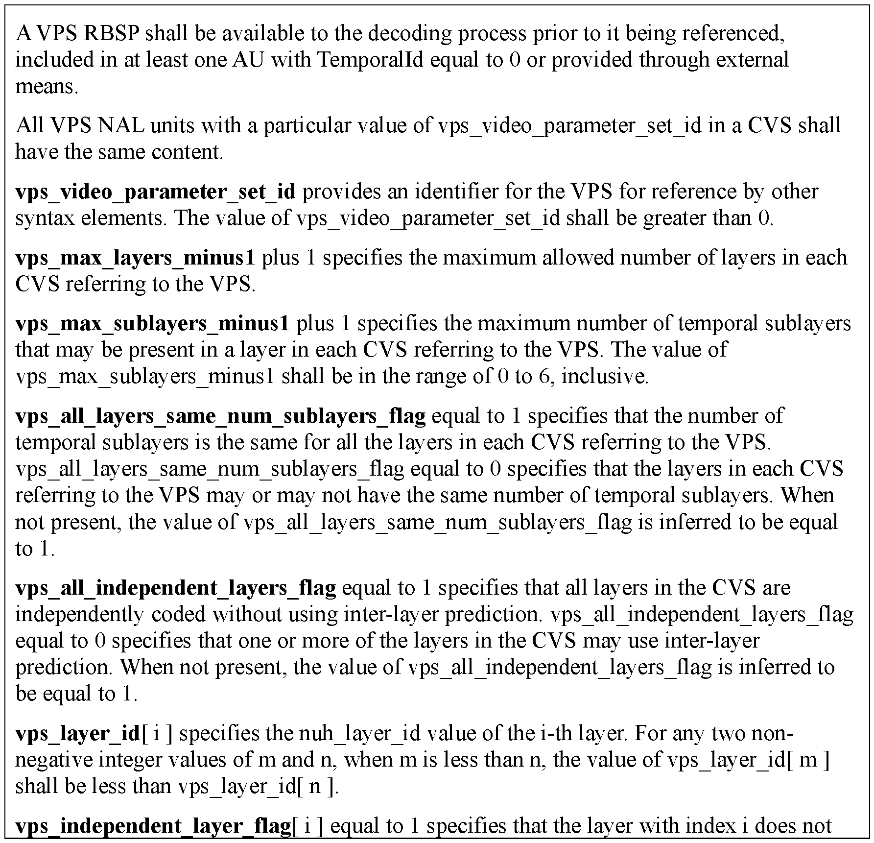
[0051] The video parameter set (VPS) was introduced to convey information that is applicable to multiple layers as well as sub-layers. The VPS was introduced to address these shortcomings as well as to enable a clean and extensible high-level design of multilayer codecs. Each layer of a given video sequence, regardless of whether they have the same or different sequence parameter sets (SPS), refer to the same VPS. The syntax and the associated semantic of the video parameter set in the current VVC draft specification are illustrated in Table 4 and Table 5, respectively. How to read Table 4 is illustrated in the appendix section of this invention, which could also be found in the VVC specification.
Table 4. Video parameter set RBSP syntax


Table 5. Video parameter set RBSP semantics


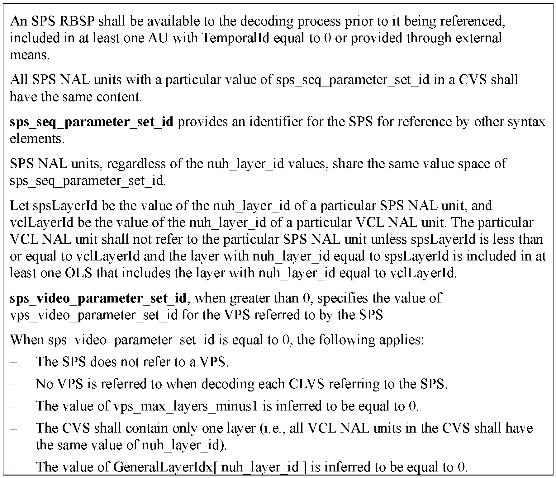
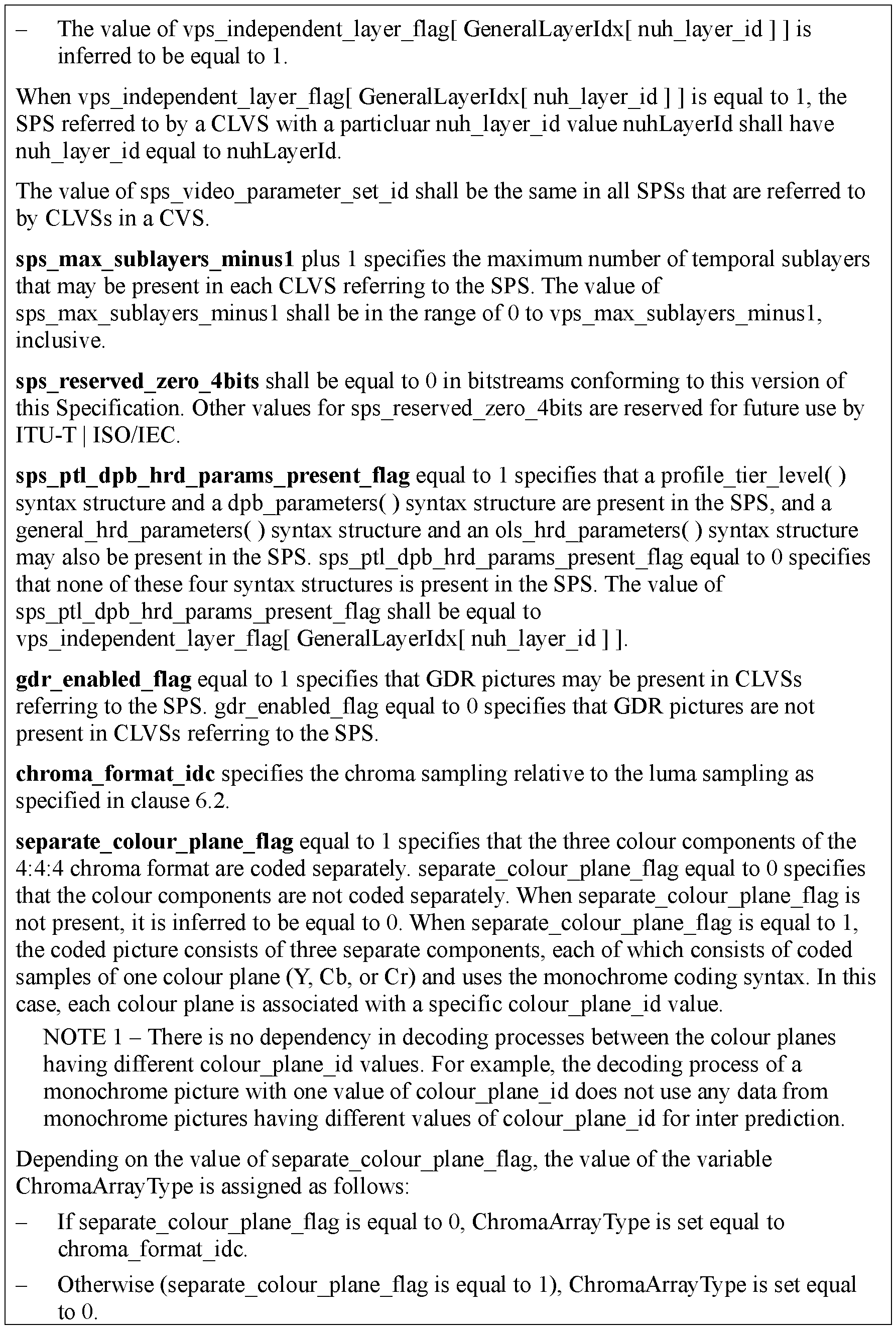
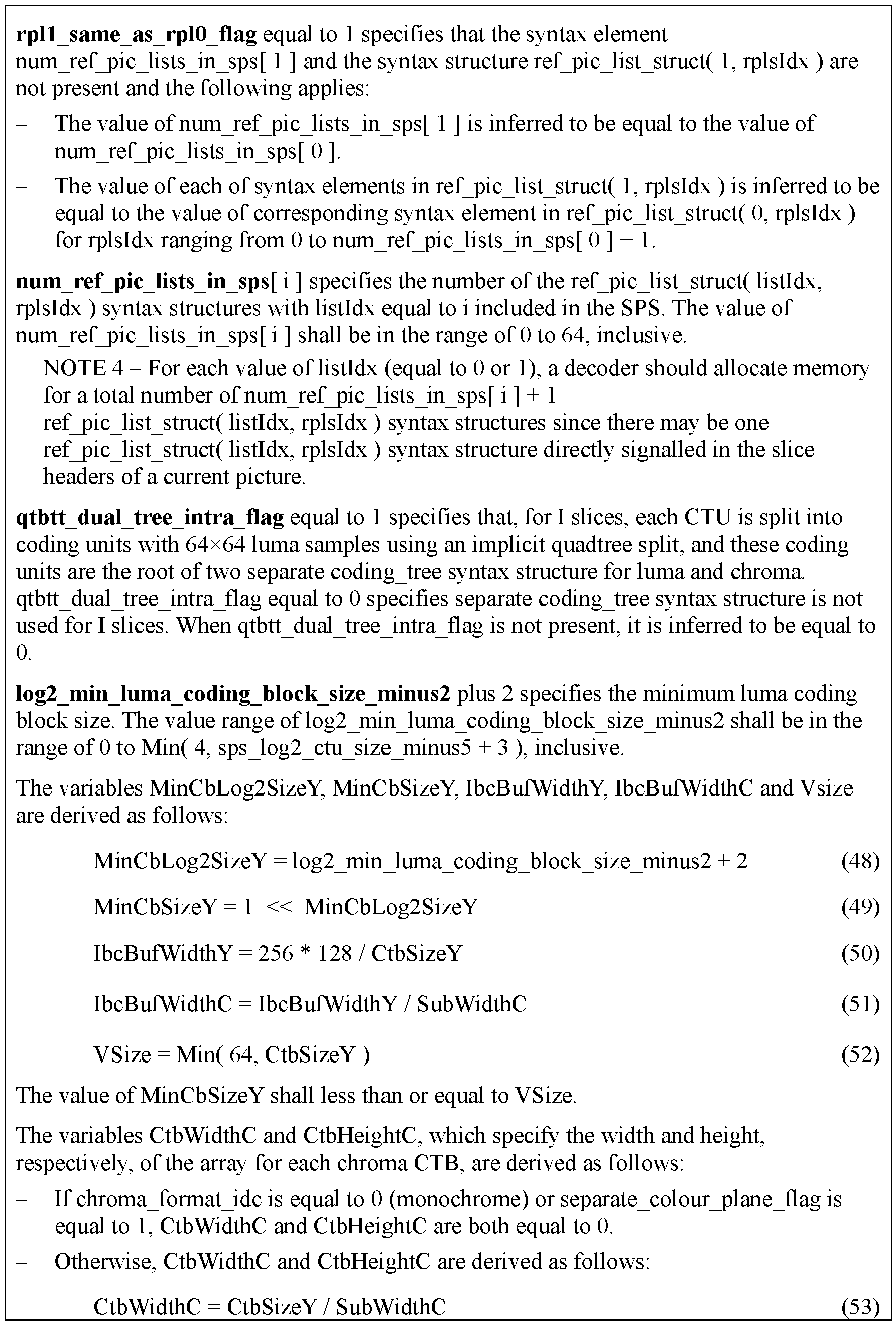
[0052] In VVC, SPSs contain information that applies to all slices of a coded video sequence. A coded video sequence starts from an instantaneous decoding refresh (IDR) picture, or a BLA picture, or a CRA picture that is the first picture in the bitstream and includes all subsequent pictures that are not an IDR or BLA picture. A bitstream consists of one or more coded video sequences. The content of the SPS can be roughly subdivided into six categories: 1) a self-reference (its own ID); 2) decoder operation point related information (profile, level,
picture size, number sub-layers, and so on); 3) enabling flags for certain tools within a profile, and associated coding tool parameters in case the tool is enabled; 4) information restricting the flexibility of structures and transform coefficient coding; 5) temporal scalability control; and 6) visual usability information (VUI), which includes HRD information. The syntax and the associated semantic of the sequence parameter set in the current VVC draft specification are illustrated in Table 6 and Table 7, respectively. How to read Table 6 is illustrated in the appendix section of this invention, which could also be found in the VVC specification.
Table 6. Sequence parameter set RBSP syntax


Table 7. Sequence parameter set RBSP semantics
 _
_


 _
_


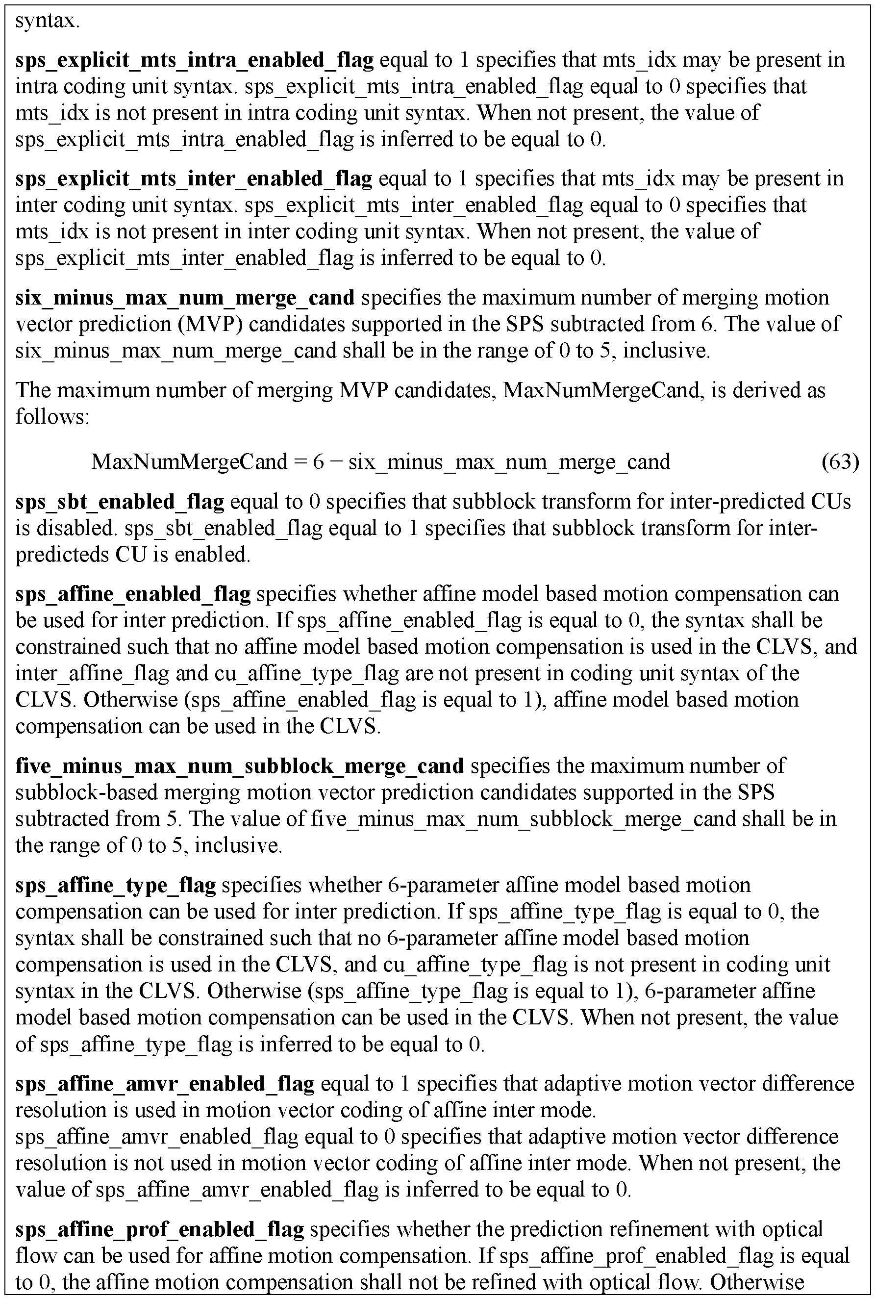


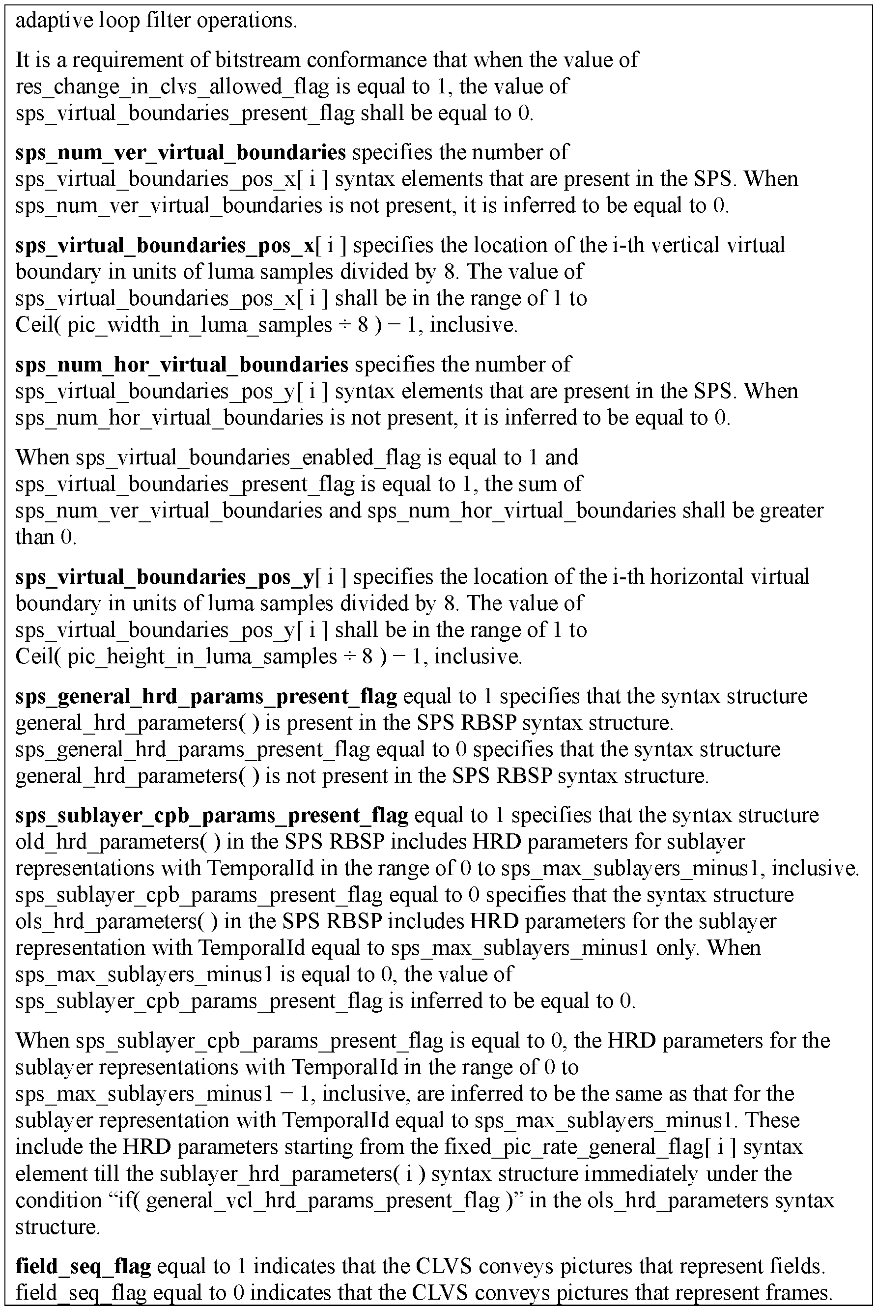

[0053] VVC’s picture parameter set (PPS) contains such information which could change from picture to picture. The PPS includes information roughly comparable to what was part of the PPS in HEVC, including: 1) a self-reference; 2) initial picture control information such as initial quantization parameter (QP), a number of flags indicating the use of, or presence of, certain tools or control information in the slice header; and 3) tiling information. The syntax and the associated semantic of the sequence parameter set in the current VVC draft specification are illustrated in Table 8 and Table 9, respectively. How to read Table 8 is illustrated in the appendix section of this invention, which could also be found in the VVC specification.
Table 8. Picture parameter set RBSP syntax


Table 9. Picture parameter set RBSP semantics

 _ _
_ _


[0054] The slice header contains information that can change from slice to slice, as well as such picture-related information that is relatively small or relevant only for a certain slice or picture types. The size of the slice header may be noticeably bigger than the PPS, particular when there are tile or wavefront entry point offsets in the slice header and RPS, prediction
weights, or reference picture list modifications are explicitly signaled. The syntax and the associated semantic of the sequence parameter set in the current VVC draft specification are illustrated in Table 10 and Table 11, respectively. How to read Table 10 is illustrated in the appendix section of this invention, which could also be found in the VVC specification.
Table 10. Picture header structure syntax


Table 11. Picture header structure semantics
 _
_


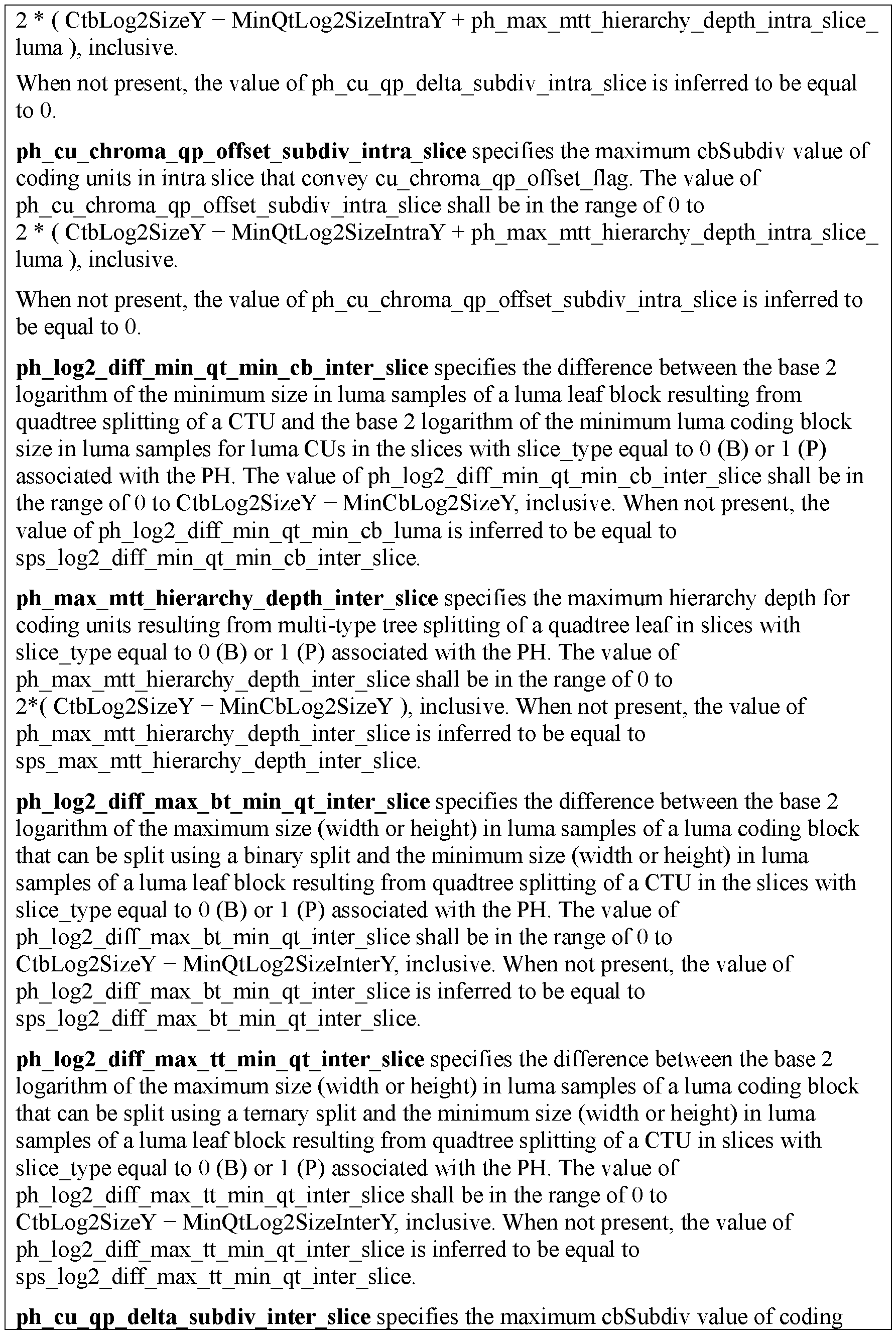

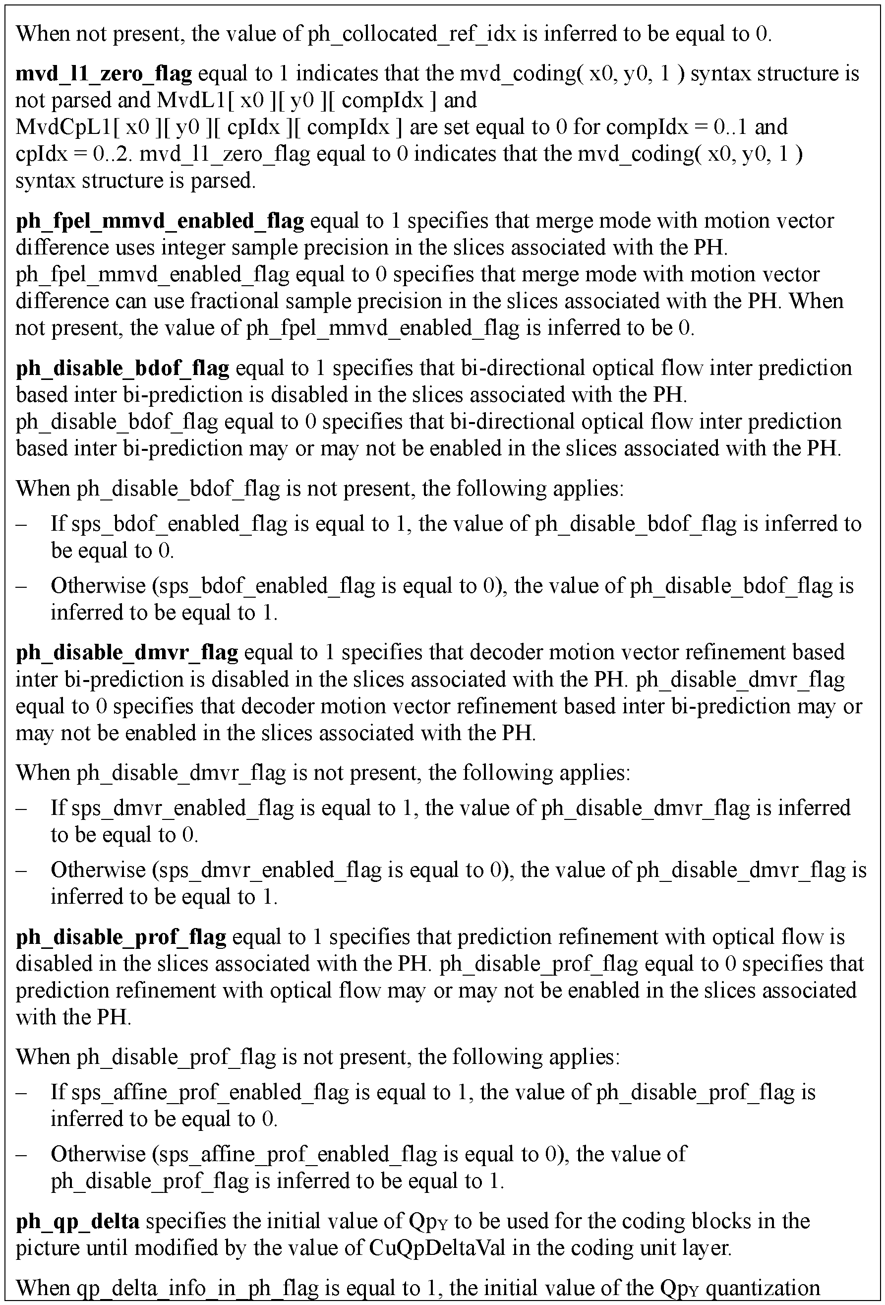


[0055] Improvements to Syntax Elements
[0056] In current VVC, when there are similar syntax elements for intra and inter prediction respectively, in some places the syntax elements related to inter prediction are defined prior to those related to intra prediction. Such an order may not be preferable, given the fact that intra prediction is allowed in all picture/slice types while inter prediction is not. It would be beneficial from a standardization point of view to always define intra prediction related syntaxes prior to those for inter prediction.
[0057] It is also observed that in the current VVC, some syntax elements that are highly correlated to each other are defined at different places in a spread manner. It would also be beneficial from a standardization point of view to group some syntaxes together.
[0058] Proposed Methods
[0059] Methods are provided to simplify and/or further improve the existing design of the high-level syntax. It is noted that the invented methods could be applied independently or jointly.
[0060] Grouping the Partition Constraint Syntax Elements by Prediction Type [0061] In this disclosure, it is proposed to rearrange the syntax elements so that the intra prediction related syntax elements are defined before those related to inter prediction. According to the disclosure, the partition constraint syntax elements are grouped by prediction type, with intra prediction related first, followed by inter prediction related. In one embodiment, the order of the partition constraint syntax elements in SPS is consistent with the order of the partition constraint syntax elements in the picture header. An example of the decoding process on VVC Draft is illustrated in Table 12 below. The changes to the VVC Draft are shown using the bold and italicized font.
Table 12. Proposed sequence parameter set RBSP syntax


[0062] Grouping the Dual- Tree Chroma Syntax Elements
[0063] In this disclosure, it is proposed to group the syntax elements related to dual-tree chroma type. In one embodiment, the partition constraint syntax elements for dual -tree chroma in SPS should be signaled together under dual-tree chroma cases. An example of the decoding process on VV C Draft is illustrated in Table 13 below. The changes to the VV C Draft are shown using bold and italicized font.
Table 13. Proposed sequence parameter set RBSP syntax
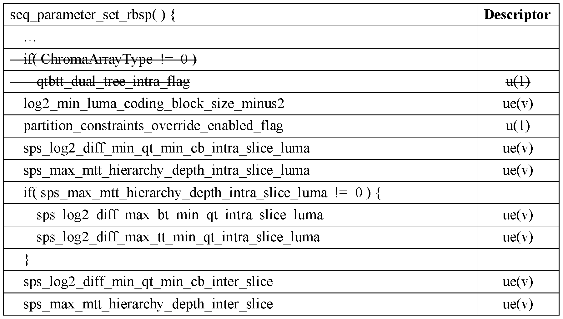

[0064] If also considering defining intra prediction related syntaxes prior to those related to inter prediction, according to the method of the disclosure, another example of the decoding process on VVC Draft is illustrated in Table 14 below. The changes to the VVC Draft are shown using bold and italicized font.
Table 14. Proposed sequence parameter set RBSP syntax


[0065] Conditionally Signaling Inter-Prediction Related Syntax Elements
[0066] As mentioned in the earlier description, according to the current VVC, intra prediction is allowed in all picture/slice types while inter prediction is not. According to this disclosure, it is proposed to add a flag in VVC syntax at a certain coding level to indicate whether inter prediction is allowed or not in a sequence, picture, and/or slice. In case inter prediction is not allowed, inter-prediction related syntaxes are not signaled at the corresponding coding level, e.g., sequence, picture, and/or slice level.
[0067] It is also proposed to add a flag in VVC syntax at a certain coding level to indicate whether inter slices such as P-slice and B-slice are allowed or not in a sequence, picture, and/or slice. In case inter slices are not allowed, inter slices related syntaxes are not signaled at the corresponding coding level, e.g., sequence, picture, and/or slice level.
[0068] Some examples are given based on the proposed inter slices allowed flags in the following section. And, the proposed inter prediction allowed flags can be used in a similar way.
[0069] When the proposed inter slice allowed flags are added at different levels. These flags can be signaled in a hierarchical manner. When the signaled flag at a higher level indicates that inter slice is not allowed, the flag at lower levels has no need to be signaled and can be inferred as 0 (which means inter slice is not allowed).
[0070] In one or more examples, a flag is added in SPS to indicate if inter slice is allowed in coding the current video sequence. In case it is not allowed, inter slice related syntax elements are not signaled in SPS. An example of the decoding process on VVC Draft is illustrated in Table 15 below. The changes to the VV C Draft are shown using bold and italicized font. It is noted that there are syntax elements other than those introduced in the example. For example, there are many inter slice (or inter prediction tools) related syntax elements such as sps weighted pred flag, sps temporal mvp enabled flag, sps amvr enabled flag, sps bdof enabled flag and so on; there are also syntax elements related to the reference picture lists such as long term ref pics flag, inter layer ref pics present flag, sps_idr_rpl_present_flag and so on. All these syntax elements related to inter prediction can selectively be controlled by the proposed flag.
Table 15. Proposed sequence parameter set RBSP syntax


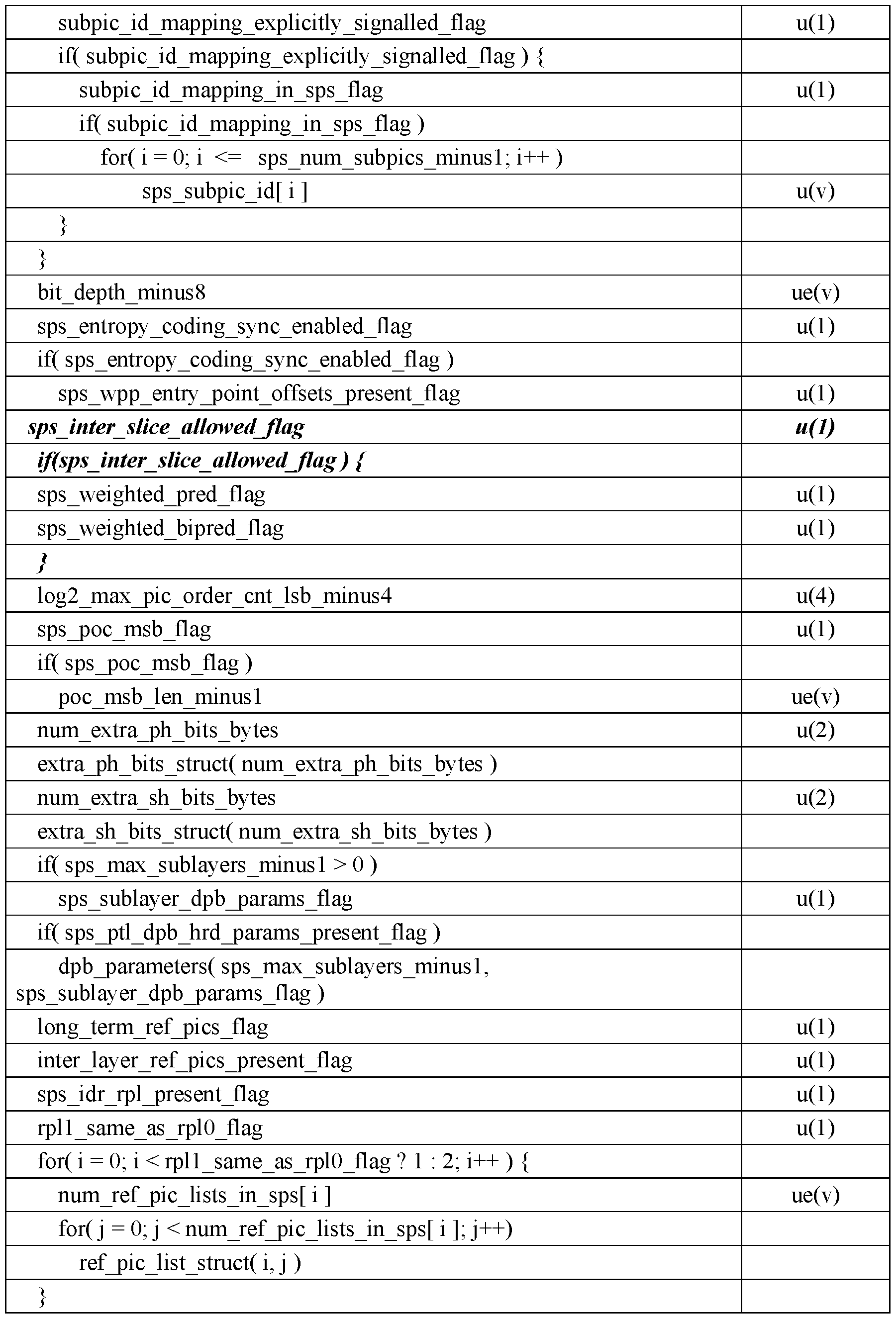


[0071] 7.4.3.3 Sequence parameter set RBSP semantics
[0072] sps_inter_slice_allowed_flag equal to 0 specifies that all coded slices of the video sequence have slice_type equal to 2 (which indicates that the coded slice is I slice), sps inter slice allowed flag equal to 1 specifies that there may or may not be one or more coded slices in the video sequence that have slice_type equal to 0 (which indicates that the coded slice is P slice) or 1 (which indicates that the coded slice is B slice).
[0073] In another example, according to the method of the disclosure, a flag is added in picture parameter set PPS to indicate if inter slice is allowed in coding the pictures associated with this PPS. In case it is not allowed, the selected inter prediction related syntax elements are not signaled in PPS.
[0074] In yet another example, according to the method of the disclosure, the inter slice allowed flags can be signaled in a hierarchical manner. A flag is added in SPS to indicate if inter slice is allowed in coding the pictures associated with this SPS, e.g., sps_inter_slice_allowed_flag. When sps_inter_slice_allowed_flag is equal to 0 (which means inter slice is not allowed), the inter slice allowed flag in picture header can be omitted for signaling and be inferred as 0 An example of the decoding process on VVC Draft is illustrated in Table 16 below. The changes to the VVC Draft are shown using bold and italicized font.
Table 16. Proposed sequence parameter set RBSP syntax
 if h i li ll d fl
 [0075] 7.4.3.7 Picture header structure semantics [0076] ph_inter_slice_allowed_flag equal to 0 specifies that all coded slices of the picture have slice_type equal to 2. ph_inter_slice_allowed_flag equal to 1 specifies that there may or may not be one or more coded slices in the picture that have slice_type equal to 0 or 1. When not present, the value of ph_inter_slice_allowed_flag is inferred to be equal to 0. [0077] FIG. 4 shows a method for decoding a video signal in accordance with the present disclosure. The method may be, for example, applied to a decoder. [0078] In step 410, the decoder may receive at least one VVC syntax flag. The at least one VVC syntax flag may include a first VVC syntax flag that indicates whether inter prediction is allowed in a corresponding coding level. [0079] In step 412, the decoder may receive, in response to a syntax element indicating that inter prediction is allowed, inter related syntax elements. [0080] In step 414, the decoder may obtain a first reference picture I(0) and a second reference picture I(1) associated with a video block in a bitstream. The first reference picture I(0) is before a current picture and the second reference picture I(1) is after the current picture in display order. [0081] In step 416, the decoder may obtain first prediction samples I(0)(i, j) of the video block from a reference block in the first reference picture I(0). The i and j represent a coordinate of one sample with the current picture. [0082] In step 418, the decoder may obtain second prediction samples I(1)(i, j) of the video block from a reference block in the second reference picture I(1). [0083] In step 420, the decoder may obtain bi-prediction samples based on the at least one VVC syntax flag, the inter related syntax elements, the first prediction samples I(0)(i, j), and the second prediction samples I(1)(i, j). [0084] Grouping the Inter-Related Syntax Elements
[0085] In this disclosure, it is proposed to rearrange the syntax elements so that the inter prediction related syntax elements are grouping in VVC syntax at certain coding level, e.g., sequence, picture, and/or slice level. According to the disclosure, it is proposed to rearrange the syntax elements related to inter slices in the sequence parameter set (SPS). An example of the decoding process on VVC Draft is illustrated in Table 17 below. The changes to the VVC Draft are shown below. The added parts are shown using bold and italicized font while the deleted parts are shown in strikethrough font.
[0075] 7.4.3.7 Picture header structure semantics [0076] ph_inter_slice_allowed_flag equal to 0 specifies that all coded slices of the picture have slice_type equal to 2. ph_inter_slice_allowed_flag equal to 1 specifies that there may or may not be one or more coded slices in the picture that have slice_type equal to 0 or 1. When not present, the value of ph_inter_slice_allowed_flag is inferred to be equal to 0. [0077] FIG. 4 shows a method for decoding a video signal in accordance with the present disclosure. The method may be, for example, applied to a decoder. [0078] In step 410, the decoder may receive at least one VVC syntax flag. The at least one VVC syntax flag may include a first VVC syntax flag that indicates whether inter prediction is allowed in a corresponding coding level. [0079] In step 412, the decoder may receive, in response to a syntax element indicating that inter prediction is allowed, inter related syntax elements. [0080] In step 414, the decoder may obtain a first reference picture I(0) and a second reference picture I(1) associated with a video block in a bitstream. The first reference picture I(0) is before a current picture and the second reference picture I(1) is after the current picture in display order. [0081] In step 416, the decoder may obtain first prediction samples I(0)(i, j) of the video block from a reference block in the first reference picture I(0). The i and j represent a coordinate of one sample with the current picture. [0082] In step 418, the decoder may obtain second prediction samples I(1)(i, j) of the video block from a reference block in the second reference picture I(1). [0083] In step 420, the decoder may obtain bi-prediction samples based on the at least one VVC syntax flag, the inter related syntax elements, the first prediction samples I(0)(i, j), and the second prediction samples I(1)(i, j). [0084] Grouping the Inter-Related Syntax Elements
[0085] In this disclosure, it is proposed to rearrange the syntax elements so that the inter prediction related syntax elements are grouping in VVC syntax at certain coding level, e.g., sequence, picture, and/or slice level. According to the disclosure, it is proposed to rearrange the syntax elements related to inter slices in the sequence parameter set (SPS). An example of the decoding process on VVC Draft is illustrated in Table 17 below. The changes to the VVC Draft are shown below. The added parts are shown using bold and italicized font while the deleted parts are shown in strikethrough font.
Table 17. Proposed sequence parameter set RBSP syntax


 vui_parameters( ) /* Specified in ITU-T H.SEI | ISO/IEC 23002-7 */ i fl 1 nt
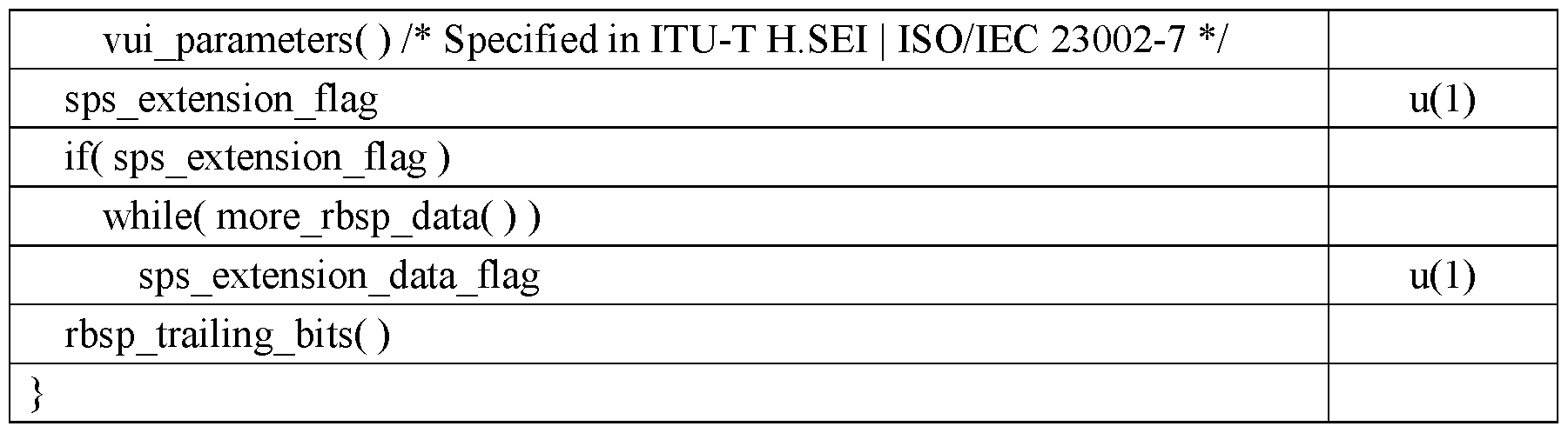 disclosure. The method may be, for example, applied to a decoder. [0087] In step 510, the decoder may receive arranged partition constraint syntax elements in SPS level. The arranged partition constraint syntax elements are arranged so that inter prediction related syntax elements are grouped in VVC syntax at a coding level. [0088] In step 512, the decoder may obtain a first reference picture I(0) and a second reference picture I(1) associated with a video block in a bitstream. The first reference picture I(0) is before a current picture and the second reference picture I(1) is after the current picture in display order. [0089] In step 514, the decoder may obtain first prediction samples I(0)(i, j) of the video block from a reference block in the first reference picture I(0). The i and j represent a coordinate of one sample with the current picture. [0090] In step 516, the decoder may obtain second prediction samples I(1)(i, j) of the video block from a reference block in the second reference picture I(1). [0091] In step 518, the decoder may obtain bi-prediction samples based on the arranged partition constraint syntax elements, the first prediction samples I(0)(i, j), and the second prediction samples I(1)(i, j). [0092] In another example of the decoding process on VVC Draft is illustrated in Table 18 below. The changes to the VVC Draft are shown below. The added parts are shown using bold and italicized font, while the deleted parts are shown in strikethrough font. Table 18. Proposed sequence parameter set RBSP syntax


[0093] According to this disclosure, it is also proposed to add a flag in VVC syntax at certain coding level to indicate whether inter slices such as P-slice and B-slice are allowed or not in a sequence, picture, and/or slice. In case inter slices are not allowed, inter slices related syntaxes are not signaled at the corresponding coding level, e.g., sequence, picture, and/or slice level. In one example, according to the method of the disclosure, a flag, sps_inter_slice_allowed_flag, is added in SPS to indicate if inter slice is allowed in coding the current video sequence. In case it is not allowed, inter slice related syntax elements are not signaled in SPS. An example of the decoding process on VVC Draft is illustrated in Table 19 below. The added parts are shown using bold and italicized font, while the deleted parts are shown in strikethrough font.
Table 19. Proposed sequence parameter set RBSP syntax


[0094] In another example of the decoding process on VVC Draft is illustrated in Table 20 below. The changes to the VVC Draft are shown below. The added parts are shown using bold and italicized font while the deleted parts are shown in strikethrough font.
Table 20. Proposed sequence parameter set RBSP syntax


[0095] FIG. 6 shows a method for decoding a video signal in accordance with the present disclosure. The method may be, for example, applied to a decoder.
[0096] In step 610, the decoder may receive a bitstream that includes VPS, SPS, PPS, picture header, and slice header for coded video data.
[0097] In step 612, the decoder may decode the VPS.
[0098] In step 614, the decoder may decode the SPS and obtain an arranged partition constraint syntax elements in SPS level.
[0099] In step 616, the decoder may decode the PPS.
[00100] In step 618, the decoder may decode the picture header.
[00101] In step 620, the decoder may decode the slice header.
[00102] In step 622, the decoder may decode the video data based on VPS, SPS, PPS, picture header and slice header.
[00103] The above methods may be implemented using an apparatus that includes one or more circuitries, which include application specific integrated circuits (ASICs), digital signal processors (DSPs), digital signal processing devices (DSPDs), programmable logic devices (PLDs), field programmable gate arrays (FPGAs), controllers, micro-controllers, microprocessors, or other electronic components. The apparatus may use the circuitries in combination with the other hardware or software components for performing the above described methods. Each module, sub-module, unit, or sub-unit disclosed above may be implemented at least partially using the one or more circuitries.
[00104] FIG. 7 shows a computing environment 710 coupled with a user interface 760. The computing environment 710 can be part of a data processing server. The computing environment 710 includes processor 720, memory 740, and I/O interface 750.
[00105] The processor 720 typically controls overall operations of the computing environment 710, such as the operations associated with the display, data acquisition, data communications, and image processing. The processor 720 may include one or more processors to execute instructions to perform all or some of the steps in the above-described methods. Moreover, the processor 720 may include one or more modules that facilitate the interaction between the processor 720 and other components. The processor may be a Central Processing Unit (CPU), a microprocessor, a single chip machine, a GPU, or the like.
[00106] The memory 740 is configured to store various types of data to support the operation
of the computing environment 710. Memory 740 may include predetermine software 742. Examples of such data include instructions for any applications or methods operated on the computing environment 710, video datasets, image data, etc. The memory 740 may be implemented by using any type of volatile or non-volatile memory devices, or a combination thereof, such as a static random access memory (SRAM), an electrically erasable programmable read-only memory (EEPROM), an erasable programmable read-only memory (EPROM), a programmable read-only memory (PROM), a read-only memory (ROM), a magnetic memory, a flash memory, a magnetic or optical disk.
[00107] The I/O interface 750 provides an interface between the processor 720 and peripheral interface modules, such as a keyboard, a click wheel, buttons, and the like. The buttons may include but are not limited to, a home button, a start scan button, and a stop scan button. The I/O interface 750 can be coupled with an encoder and decoder.
[00108] In some embodiments, there is also provided a non-transitory computer-readable storage medium comprising a plurality of programs, such as comprised in the memory 740, executable by the processor 720 in the computing environment 710, for performing the above- described methods. For example, the non-transitory computer-readable storage medium may be a ROM, a RAM, a CD-ROM, a magnetic tape, a floppy disc, an optical data storage device or the like.
[00109] The non-transitory computer-readable storage medium has stored therein a plurality of programs for execution by a computing device having one or more processors, where the plurality of programs when executed by the one or more processors, cause the computing device to perform the above-described method for motion prediction.
[00110] In some embodiments, the computing environment 710 may be implemented with one or more application-specific integrated circuits (ASICs), digital signal processors (DSPs), digital signal processing devices (DSPDs), programmable logic devices (PLDs), field- programmable gate arrays (FPGAs), graphical processing units (GPUs), controllers, microcontrollers, microprocessors, or other electronic components, for performing the above
methods.
[00111] Other examples of the disclosure will be apparent to those skilled in the art from consideration of the specification and practice of the disclosure disclosed here. This application is intended to cover any variations, uses, or adaptations of the disclosure following the general principles thereof and including such departures from the present disclosure as come within known or customary practice in the art. It is intended that the specification and examples be considered as exemplary only.
[00112] It will be appreciated that the present disclosure is not limited to the exact examples described above and illustrated in the accompanying drawings, and that various modifications and changes can be made without departing from the scope thereof.
Claims
CLAIMS What is claimed is: 1. A method for decoding a video signal, comprising: receiving, by a decoder, at least one versatile video coding (VVC) syntax flag, wherein the at least one VVC syntax flag comprises a first VVC syntax flag that indicates whether inter prediction is allowed in a corresponding coding level; receiving, by the decoder and in response to a syntax element indicating that inter prediction is allowed, inter related syntax elements; obtaining, at the decoder, a first reference picture I(0) and a second reference picture I(1) associated with a video block in a bitstream, wherein the first reference picture I(0) is before a current picture and the second reference picture I(1) is after the current picture in display order; obtaining, at the decoder, first prediction samples I(0)(i, j) of the video block from a reference block in the first reference picture I(0), wherein i and j represent a coordinate of one sample with the current picture; obtaining, at the decoder, second prediction samples I(1)(i, j) of the video block from a reference block in the second reference picture I(1); and obtaining, at the decoder, bi-prediction samples based on the at least one VVC syntax flag, the inter related syntax elements, the first prediction samples I(0)(i, j), and the second prediction samples I(1)(i, j).
2. The method of claim 1, wherein when the first VVC syntax flag indicates inter prediction is not allowed, inter prediction related syntaxes are not signaled at a corresponding coding level.
3. The method of claim 1, wherein the at least one VVC syntax flag is signaled in a hierarchical manner for inferring when inter slice is not allowed.
4. The method of claim 3, wherein the at least one VVC syntax flag comprises a second VVC syntax flag that indicates whether inter slices are allowed in a corresponding coding level, wherein inter slices comprise P-slice and B-slice, and wherein the second VVC syntax flag comprises a sps_inter_slice_allowed_flag flag.
5. The method of claim 4, wherein when the second VVC syntax flag indicates that inter slices are not allowed, inter slice related syntaxes are not signaled at a corresponding coding level.
6. The method of claim 4, wherein the second VVC syntax flag is signaled in sequence parameter set (SPS) level and indicates whether an inter slice is allowed in decoding a current video sequence.
7. The method of claim 6, further comprising: receiving, at the decoder, when the second VVC syntax flag is signaled in the SPS level and indicates that the inter slice is allowed in decoding the current video, a sps_weighted_pred_flag flag, a sps_weighted_bipred_flag flag, a sps_log2_diff_min_qt_min_cb_inter_slice value, a sps max mtt hierarchy depth inter slice value, a sps ref wraparound enabled flag flag, a sps temporal mvp enabled flag flag, a sps explicit mts inter enabled flag flag, a six minus max num merge cand value, a sps_sbt_enabled_flag flag, a sps_bcw_enabled_flag flag, a sps_ciip_enabled_flag flag, and a log2_parallel_merge_level_minus2 value.
8. The method of claim 4, wherein the second VVC syntax flag is signaled in picture parameter set (PPS) level and indicates whether an inter slice is allowed in decoding a current video sequence.
9. The method of claim 8, wherein when the second VVC syntax flag indicates that inter slice is not allowed, a ph_inter_slice_allowed_flag flag is not received.
10. A method for decoding a video signal, comprising: receiving, by a decoder, arranged partition constraint syntax elements in sequence parameter set (SPS) level, wherein the arranged partition constraint syntax elements are arranged so that inter prediction related syntax elements are grouped in versatile video coding (VVC) syntax at a coding level; obtaining, at the decoder, a first reference picture I(0) and a second reference picture I(1) associated with a video block in a bitstream, wherein the first reference picture I(0) is before a current picture and the second reference picture I(1) is after the current picture in display order; obtaining, at the decoder, first prediction samples I(0)(i, j) of the video block from a reference block in the first reference picture I(0), wherein i and j represent a coordinate of one sample with the current picture; obtaining, at the decoder, second prediction samples I(1)(i, j) of the video block from a reference block in the second reference picture I(1); and obtaining, at the decoder, bi-prediction samples based on the arranged partition constraint syntax elements, the first prediction samples I(0)(i, j), and the second prediction samples I(1)(i, j).
11. The method of claim 10, wherein receiving, by the decoder, the arranged partition constraint syntax elements in the SPS level comprises: receiving, by the decoder, the arranged partition constraint syntax elements in the SPS level, wherein the arranged partition constraint syntax elements are arranged by: signaling a long_term_ref_pics_flag flag; signaling a inter_layer_ref_pics_present_flag flag; setting a num_ref_pic_lists_in_sps value; setting a ref_pic_list_struct value;
signaling a sps_weighted_pred_flag flag; setting a six minus max num merge cand value; signaling a sps_sbt_enabled_flag flag; and setting a log2_parallel_merge_level_minus2 value.
12. The method of claim 10, wherein receiving, by the decoder, the arranged partition constraint syntax elements in the SPS level comprises: receiving, by the decoder, the arranged partition constraint syntax elements in the SPS level, wherein the arranged partition constraint syntax elements are arranged by: signaling a sps_mts_enabled_flag flag; determining that sps_mts_enabled_flag is set; signaling a sps_explicit_mts_intra_enabled_flag; determining that sps_inter_slice_allowed_flag is set; determining that sps_mts_enabled_flag is set; signaling a sps_explicit_mts_inter_enabled_flag flag; setting a sps_log2_diff_min_qt_min_cb_inter_slice value; determining that a sps_max_mtt_hierarchy_depth_inter_slice is not 0; setting sps_log2_diff_max_bt_min_qt_inter_slice value; signaling a sps_weighted_pred_flag flag; setting a six minus max num merge cand value; determining that sps_affme_enabled_flag flag is set; setting a five_minus_max_num_subblock_merge_cand value; and setting a log2_parallel_merge_level_minus2 value.
13. The method of claim 10, further comprising: receiving, by the decoder, a VVC syntax flag at a coding level, wherein the VVC syntax flag comprises a sps_inter_slice_allowed_flag flag that indicates whether inter slices
are allowed in a corresponding coding level, and wherein the inter slices comprise P-slice and B-slice.
14. The method of claim 13, wherein when the VVC syntax flag indicates inter prediction is not allowed, inter slices related syntaxes are not signaled at a corresponding coding level.
15. The method of claim 13, further comprising: receiving, at the decoder, when the VVC syntax flag is signaled in the SPS level and indicates that the inter slice is allowed in decoding the current video, a sps_log2_diff_min_qt_min_cb_inter_slice value, a long_term_ref_pics_flag flag, a sps_weighted_pred_flag flag, a six minus max num merge cand value, a sps_bcw_enabled_flag flag, and a sps_explicit_mts_inter_enabled_flag flag.
16. The method of claim 13, further comprising: determining, at the decoder, whether ChromaArrayType value is not 0; and receiving, when the VVC syntax flag is signaled in the SPS level and indicates that the inter slice is allowed in decoding the current video, a sps_mts_enabled_flag flag, a sps_log2_diff_min_qt_min_cb_inter_slice value, a sps_weighted_pred_flag flag, a six minus max num merge cand value, and a sps bcw enabled flag flag.
17. A computing device, comprising: one or more processors; and a non-transitory computer-readable storage medium storing instructions executable by the one or more processors, wherein the one or more processors are configured to: receive at least one versatile video coding (VVC) syntax flag, wherein the at least one VVC syntax flag comprises a first VVC syntax flag that indicates whether inter prediction is allowed in a corresponding coding level;
in response to a syntax element indicating that inter prediction is allowed, receive inter related syntax elements; obtain a first reference picture I(0) and a second reference picture I(1) associated with a video block in a bitstream, wherein the first reference picture I(0) is before a current picture and the second reference picture I(1) is after the current picture in display order; obtain first prediction samples I(0)(i, j) of the video block from a reference block in the first reference picture I(0), wherein i and j represent a coordinate of one sample with the current picture; obtain second prediction samples I(1)(i, j) of the video block from a reference block in the second reference picture I(1); and obtain bi-prediction samples based on the at least one VVC syntax flag, the inter related syntax elements, the first prediction samples I(0)(i, j), and the second prediction samples I(1)(i, j).
18. The computing device of claim 17, wherein when the first VVC syntax flag indicates inter prediction is not allowed, inter prediction related syntaxes are not signaled at a corresponding coding level.
19. The computing device of claim 17, wherein the at least one VVC syntax flag is signaled in a hierarchical manner for inferring when inter slice is not allowed.
20. The computing device of claim 19, wherein the at least one VVC syntax flag comprises a second VVC syntax flag that indicates whether inter slices are allowed in a corresponding coding level, wherein inter slices comprise P-slice and B-slice, and wherein the second VVC syntax flag comprises a sps_inter_slice_allowed_flag flag.
21. The computing device of claim 20, wherein when the second VVC syntax flag indicates that inter slices are not allowed, inter slice related syntaxes are not signaled at a
corresponding coding level.
22. The computing device of claim 20, wherein the second VVC syntax flag is signaled in sequence parameter set (SPS) level and indicates whether an inter slice is allowed in decoding a current video sequence.
23. The computing device of claim 22, wherein the one or more processors are further configured to: receive, when the second VVC syntax flag is signaled in the SPS level and indicates that the inter slice is allowed in decoding the current video, a sps_weighted_pred_flag flag, a sps_weighted_bipred_flag flag, a sps_log2_diff_min_qt_min_cb_inter_slice value, a sps max mtt hierarchy depth inter slice value, a sps ref wraparound enabled flag flag, a sps temporal mvp enabled flag flag, a sps explicit mts inter enabled flag flag, a six minus max num merge cand value, a sps sbt enabled flag flag, a sps_bcw_enabled_flag flag, a sps_ciip_enabled_flag flag, and a log2_parallel_merge_level_minus2 value.
24. The computing device of claim 20, wherein the second VVC syntax flag is signaled in picture parameter set (PPS) level and indicates whether an inter slice is allowed in decoding a current video sequence.
25. The computing device of claim 24, wherein when the second VVC syntax flag indicates that inter slice is not allowed, a ph_inter_slice_allowed_flag flag is not received.
26. A non-transitory computer-readable storage medium storing a plurality of programs for execution by a computing device having one or more processors, wherein the plurality of programs, when executed by the one or more processors, cause the computing
device to perform acts comprising: receiving, by a decoder, arranged partition constraint syntax elements in sequence parameter set (SPS) level, wherein the arranged partition constraint syntax elements are arranged so that inter prediction related syntax elements are grouped in versatile video coding (VVC) syntax at a coding level; obtaining, at the decoder, a first reference picture I(0) and a second reference picture I(1) associated with a video block in a bitstream, wherein the first reference picture I(0) is before a current picture and the second reference picture I(1) is after the current picture in display order; obtaining, at the decoder, first prediction samples I(0)(i, j) of the video block from a reference block in the first reference picture I(0), wherein i and j represent a coordinate of one sample with the current picture; obtaining, at the decoder, second prediction samples I(1)(i, j) of the video block from a reference block in the second reference picture I(1); and obtaining, at the decoder, bi-prediction samples based on the arranged partition constraint syntax elements, the first prediction samples I(0)(i, j), and the second prediction samples I(1)(i, j).
27. The non-transitory computer-readable storage medium of claim 26, wherein the plurality of programs further cause the computing device to perform: receiving, by the decoder, the arranged partition constraint syntax elements in the SPS level, wherein the arranged partition constraint syntax elements are arranged by: signaling a long_term_ref_pics_flag flag; signaling a inter_layer_ref_pics_present_flag flag; setting a num_ref_pic_lists_in_sps value; setting a ref_pic_list_struct value; signaling a sps_weighted_pred_flag flag; setting a six_minus_max_num_merge_cand value; signaling a sps_sbt_enabled_flag flag; and
setting a log2_parallel_merge_level_minus2 value.
28. The non-transitory computer-readable storage medium of claim 26, wherein the plurality of programs further cause the computing device to perform: receiving, by the decoder, the arranged partition constraint syntax elements in the SPS level, wherein the arranged partition constraint syntax elements are arranged by: signaling a sps_mts_enabled_flag flag; determining that sps_mts_enabled_flag is set; signaling a sps_explicit_mts_intra_enabled_flag; determining that sps_inter_slice_allowed_flag is set; determining that sps_mts_enabled_flag is set; signaling a sps_explicit_mts_inter_enabled_flag flag; setting a sps_log2_diff_min_qt_min_cb_inter_slice value; determining that a sps max mtt hierarchy depth inter slice is not 0; setting sps_log2_diff_max_bt_min_qt_inter_slice value; signaling a sps_weighted_pred_flag flag; setting a six minus max num merge cand value; determining that sps_affme_enabled_flag flag is set; setting a five_minus_max_num_subblock_merge_cand value; and setting a log2_parallel_merge_level_minus2 value.
29. The non-transitory computer-readable storage medium of claim 26, wherein the plurality of programs further cause the computing device to perform: receiving, by the decoder, a VVC syntax flag at a coding level, wherein the VVC syntax flag comprises a sps_inter_slice_allowed_flag flag that indicates whether inter slices are allowed in a corresponding coding level, and wherein the inter slices comprise P-slice and B-slice.
30. The non-transitory computer-readable storage medium of claim 29, wherein when the VVC syntax flag indicates inter prediction is not allowed, inter slices related syntaxes are not signaled at a corresponding coding level.
31. The non-transitory computer-readable storage medium of claim 29, wherein the plurality of programs further cause the computing device to perform: receiving, at the decoder, when the VVC syntax flag is signaled in the SPS level and indicates that the inter slice is allowed in decoding the current video, a sps_log2_diff_min_qt_min_cb_inter_slice value, a long_term_ref_pics_flag flag, a sps_weighted_pred_flag flag, a six minus max num merge cand value, a sps_bcw_enabled_flag flag, and a sps_explicit_mts_inter_enabled_flag flag.
32. The non-transitory computer-readable storage medium of claim 29, wherein the plurality of programs further cause the computing device to perform: determining, at the decoder, whether ChromaArrayType value is not 0; and receiving, when the VVC syntax flag is signaled in the SPS level and indicates that the inter slice is allowed in decoding the current video, a sps_mts_enabled_flag flag, a sps_log2_diff_min_qt_min_cb_inter_slice value, a sps_weighted_pred_flag flag, a six minus max num merge cand value, and a sps bcw enabled flag flag.
Priority Applications (7)
| Application Number | Priority Date | Filing Date | Title |
|---|---|---|---|
| EP25201954.2A EP4642029A3 (en) | 2020-04-03 | 2021-04-02 | Methods and devices for high-level syntax in video coding |
| CN202311191514.5A CN117221604B (en) | 2020-04-03 | 2021-04-02 | Method and apparatus for high level syntax in video coding |
| EP21782301.2A EP4128792B1 (en) | 2020-04-03 | 2021-04-02 | Methods and devices for high-level syntax in video coding |
| ES21782301T ES3052741T3 (en) | 2020-04-03 | 2021-04-02 | Methods and devices for high-level syntax in video coding |
| CN202180039854.9A CN115715467A (en) | 2020-04-03 | 2021-04-02 | Method and apparatus for high level syntax in video coding and decoding |
| US17/959,021 US12120355B2 (en) | 2020-04-03 | 2022-10-03 | Methods and devices for high-level syntax in video coding |
| US18/830,401 US20250016376A1 (en) | 2020-04-03 | 2024-09-10 | Methods and devices for high-level syntax in video coding |
Applications Claiming Priority (4)
| Application Number | Priority Date | Filing Date | Title |
|---|---|---|---|
| US202063005203P | 2020-04-03 | 2020-04-03 | |
| US63/005,203 | 2020-04-03 | ||
| US202063005309P | 2020-04-04 | 2020-04-04 | |
| US63/005,309 | 2020-04-04 |
Related Child Applications (1)
| Application Number | Title | Priority Date | Filing Date |
|---|---|---|---|
| US17/959,021 Continuation US12120355B2 (en) | 2020-04-03 | 2022-10-03 | Methods and devices for high-level syntax in video coding |
Publications (1)
| Publication Number | Publication Date |
|---|---|
| WO2021203039A1 true WO2021203039A1 (en) | 2021-10-07 |
Family
ID=77929680
Family Applications (1)
| Application Number | Title | Priority Date | Filing Date |
|---|---|---|---|
| PCT/US2021/025635 Ceased WO2021203039A1 (en) | 2020-04-03 | 2021-04-02 | Methods and devices for high-level syntax in video coding |
Country Status (5)
| Country | Link |
|---|---|
| US (2) | US12120355B2 (en) |
| EP (2) | EP4642029A3 (en) |
| CN (2) | CN117221604B (en) |
| ES (1) | ES3052741T3 (en) |
| WO (1) | WO2021203039A1 (en) |
Families Citing this family (2)
| Publication number | Priority date | Publication date | Assignee | Title |
|---|---|---|---|---|
| CN114556915B (en) * | 2019-10-10 | 2023-11-10 | 北京字节跳动网络技术有限公司 | Deblocking of coded blocks in geometric segmentation mode |
| CN117957841A (en) * | 2021-10-01 | 2024-04-30 | Lg 电子株式会社 | Image compilation method and device based on GPM |
Citations (4)
| Publication number | Priority date | Publication date | Assignee | Title |
|---|---|---|---|---|
| WO2019001785A1 (en) * | 2017-06-30 | 2019-01-03 | Huawei Technologies Co., Ltd. | Overlapped search space for bi-predictive motion vector refinement |
| US20190166381A1 (en) * | 2011-03-03 | 2019-05-30 | Sun Patent Trust | Moving picture coding method, moving picture decoding method, moving picture coding apparatus, moving picture decoding apparatus, and moving picture coding and decoding apparatus |
| US20190327488A1 (en) * | 2010-03-17 | 2019-10-24 | Ntt Docomo, Inc. | Moving image prediction encoding/decoding system |
| WO2020060843A1 (en) * | 2018-09-19 | 2020-03-26 | Interdigital Vc Holdings, Inc. | Generalized bi-prediction index coding |
Family Cites Families (5)
| Publication number | Priority date | Publication date | Assignee | Title |
|---|---|---|---|---|
| US9247249B2 (en) * | 2011-04-20 | 2016-01-26 | Qualcomm Incorporated | Motion vector prediction in video coding |
| WO2015101716A1 (en) * | 2014-01-03 | 2015-07-09 | Nokia Technologies Oy | Parameter set coding |
| US20170134732A1 (en) * | 2015-11-05 | 2017-05-11 | Broadcom Corporation | Systems and methods for digital media communication using syntax planes in hierarchical trees |
| US11330271B2 (en) * | 2018-09-18 | 2022-05-10 | Nokia Technologies Oy | Method and apparatus for non-binary profile constraint signaling for video coding |
| JP7355829B2 (en) * | 2018-09-18 | 2023-10-03 | 華為技術有限公司 | Video encoder, video decoder, and corresponding method |
-
2021
- 2021-04-02 EP EP25201954.2A patent/EP4642029A3/en active Pending
- 2021-04-02 ES ES21782301T patent/ES3052741T3/en active Active
- 2021-04-02 CN CN202311191514.5A patent/CN117221604B/en active Active
- 2021-04-02 WO PCT/US2021/025635 patent/WO2021203039A1/en not_active Ceased
- 2021-04-02 CN CN202180039854.9A patent/CN115715467A/en active Pending
- 2021-04-02 EP EP21782301.2A patent/EP4128792B1/en active Active
-
2022
- 2022-10-03 US US17/959,021 patent/US12120355B2/en active Active
-
2024
- 2024-09-10 US US18/830,401 patent/US20250016376A1/en active Pending
Patent Citations (4)
| Publication number | Priority date | Publication date | Assignee | Title |
|---|---|---|---|---|
| US20190327488A1 (en) * | 2010-03-17 | 2019-10-24 | Ntt Docomo, Inc. | Moving image prediction encoding/decoding system |
| US20190166381A1 (en) * | 2011-03-03 | 2019-05-30 | Sun Patent Trust | Moving picture coding method, moving picture decoding method, moving picture coding apparatus, moving picture decoding apparatus, and moving picture coding and decoding apparatus |
| WO2019001785A1 (en) * | 2017-06-30 | 2019-01-03 | Huawei Technologies Co., Ltd. | Overlapped search space for bi-predictive motion vector refinement |
| WO2020060843A1 (en) * | 2018-09-19 | 2020-03-26 | Interdigital Vc Holdings, Inc. | Generalized bi-prediction index coding |
Non-Patent Citations (2)
| Title |
|---|
| BENJAMIN BROSS , JIANLE CHEN , SHAN LIU , YE-KUI WANG: "Versatile Video Coding (Draft 8)", 17. JVET MEETING; 20200107 - 20200117; BRUSSELS; (THE JOINT VIDEO EXPLORATION TEAM OF ISO/IEC JTC1/SC29/WG11 AND ITU-T SG.16 ), no. JVET-Q2001-vE, 12 March 2020 (2020-03-12), pages 1 - 510, XP030285390 * |
| See also references of EP4128792A4 * |
Also Published As
| Publication number | Publication date |
|---|---|
| EP4642029A3 (en) | 2026-01-07 |
| CN117221604B (en) | 2024-11-05 |
| US20250016376A1 (en) | 2025-01-09 |
| US12120355B2 (en) | 2024-10-15 |
| US20230103542A1 (en) | 2023-04-06 |
| EP4128792C0 (en) | 2025-10-22 |
| EP4128792A1 (en) | 2023-02-08 |
| EP4128792A4 (en) | 2023-05-24 |
| EP4642029A2 (en) | 2025-10-29 |
| ES3052741T3 (en) | 2026-01-13 |
| CN115715467A (en) | 2023-02-24 |
| EP4128792B1 (en) | 2025-10-22 |
| CN117221604A (en) | 2023-12-12 |
Similar Documents
| Publication | Publication Date | Title |
|---|---|---|
| US11758193B2 (en) | Signaling high-level information in video and image coding | |
| JP7407300B2 (en) | adaptive loop filtering | |
| US8553781B2 (en) | Methods and apparatus for decoded picture buffer (DPB) management in single loop decoding for multi-view video | |
| US12452461B2 (en) | High-level syntax for video coding | |
| US20230031964A1 (en) | Methods and devices for high-level syntax in video coding | |
| US20250016376A1 (en) | Methods and devices for high-level syntax in video coding | |
| US12542928B2 (en) | General constraint information for video coding | |
| CN115380538B (en) | Decoding based on bidirectional image conditions | |
| WO2021236888A1 (en) | General constraint information and signaling of syntax elements in video coding | |
| CN120476584A (en) | Method, device and medium for video processing | |
| CN120380750A (en) | Method, apparatus and medium for video processing | |
| US20250240458A1 (en) | Method, apparatus, and medium for video processing | |
| CN121444439A (en) | Methods, apparatus and media for video processing | |
| CN121040051A (en) | Methods, apparatus and media for video processing | |
| CN121014201A (en) | Methods, apparatus and media for video processing | |
| CN120500843A (en) | Method, apparatus and medium for video processing | |
| CN119948868A (en) | Method, device and medium for video processing |
Legal Events
| Date | Code | Title | Description |
|---|---|---|---|
| 121 | Ep: the epo has been informed by wipo that ep was designated in this application |
Ref document number: 21782301 Country of ref document: EP Kind code of ref document: A1 |
|
| NENP | Non-entry into the national phase |
Ref country code: DE |
|
| ENP | Entry into the national phase |
Ref document number: 2021782301 Country of ref document: EP Effective date: 20221031 |
|
| WWG | Wipo information: grant in national office |
Ref document number: 2021782301 Country of ref document: EP |