WO2021205756A1 - レーザ加工装置及びレーザ加工方法 - Google Patents
レーザ加工装置及びレーザ加工方法 Download PDFInfo
- Publication number
- WO2021205756A1 WO2021205756A1 PCT/JP2021/005956 JP2021005956W WO2021205756A1 WO 2021205756 A1 WO2021205756 A1 WO 2021205756A1 JP 2021005956 W JP2021005956 W JP 2021005956W WO 2021205756 A1 WO2021205756 A1 WO 2021205756A1
- Authority
- WO
- WIPO (PCT)
- Prior art keywords
- light
- laser
- hologram
- irradiation
- workpiece
- Prior art date
- Legal status (The legal status is an assumption and is not a legal conclusion. Google has not performed a legal analysis and makes no representation as to the accuracy of the status listed.)
- Ceased
Links
Images


Classifications
-
- B—PERFORMING OPERATIONS; TRANSPORTING
- B23—MACHINE TOOLS; METAL-WORKING NOT OTHERWISE PROVIDED FOR
- B23K—SOLDERING OR UNSOLDERING; WELDING; CLADDING OR PLATING BY SOLDERING OR WELDING; CUTTING BY APPLYING HEAT LOCALLY, e.g. FLAME CUTTING; WORKING BY LASER BEAM
- B23K26/00—Working by laser beam, e.g. welding, cutting or boring
- B23K26/02—Positioning or observing the workpiece, e.g. with respect to the point of impact; Aligning, aiming or focusing the laser beam
- B23K26/03—Observing, e.g. monitoring, the workpiece
-
- B—PERFORMING OPERATIONS; TRANSPORTING
- B23—MACHINE TOOLS; METAL-WORKING NOT OTHERWISE PROVIDED FOR
- B23K—SOLDERING OR UNSOLDERING; WELDING; CLADDING OR PLATING BY SOLDERING OR WELDING; CUTTING BY APPLYING HEAT LOCALLY, e.g. FLAME CUTTING; WORKING BY LASER BEAM
- B23K26/00—Working by laser beam, e.g. welding, cutting or boring
- B23K26/02—Positioning or observing the workpiece, e.g. with respect to the point of impact; Aligning, aiming or focusing the laser beam
- B23K26/06—Shaping the laser beam, e.g. by masks or multi-focusing
- B23K26/067—Dividing the beam into multiple beams, e.g. multi-focusing
-
- G—PHYSICS
- G03—PHOTOGRAPHY; CINEMATOGRAPHY; ANALOGOUS TECHNIQUES USING WAVES OTHER THAN OPTICAL WAVES; ELECTROGRAPHY; HOLOGRAPHY
- G03H—HOLOGRAPHIC PROCESSES OR APPARATUS
- G03H1/00—Holographic processes or apparatus using light, infrared or ultraviolet waves for obtaining holograms or for obtaining an image from them; Details peculiar thereto
- G03H1/22—Processes or apparatus for obtaining an optical image from holograms
- G03H1/2294—Addressing the hologram to an active spatial light modulator
-
- B—PERFORMING OPERATIONS; TRANSPORTING
- B23—MACHINE TOOLS; METAL-WORKING NOT OTHERWISE PROVIDED FOR
- B23K—SOLDERING OR UNSOLDERING; WELDING; CLADDING OR PLATING BY SOLDERING OR WELDING; CUTTING BY APPLYING HEAT LOCALLY, e.g. FLAME CUTTING; WORKING BY LASER BEAM
- B23K26/00—Working by laser beam, e.g. welding, cutting or boring
- B23K26/02—Positioning or observing the workpiece, e.g. with respect to the point of impact; Aligning, aiming or focusing the laser beam
- B23K26/03—Observing, e.g. monitoring, the workpiece
- B23K26/032—Observing, e.g. monitoring, the workpiece using optical means
-
- B—PERFORMING OPERATIONS; TRANSPORTING
- B23—MACHINE TOOLS; METAL-WORKING NOT OTHERWISE PROVIDED FOR
- B23K—SOLDERING OR UNSOLDERING; WELDING; CLADDING OR PLATING BY SOLDERING OR WELDING; CUTTING BY APPLYING HEAT LOCALLY, e.g. FLAME CUTTING; WORKING BY LASER BEAM
- B23K26/00—Working by laser beam, e.g. welding, cutting or boring
- B23K26/02—Positioning or observing the workpiece, e.g. with respect to the point of impact; Aligning, aiming or focusing the laser beam
- B23K26/06—Shaping the laser beam, e.g. by masks or multi-focusing
- B23K26/062—Shaping the laser beam, e.g. by masks or multi-focusing by direct control of the laser beam
- B23K26/0622—Shaping the laser beam, e.g. by masks or multi-focusing by direct control of the laser beam by shaping pulses
- B23K26/0624—Shaping the laser beam, e.g. by masks or multi-focusing by direct control of the laser beam by shaping pulses using ultrashort pulses, i.e. pulses of 1 ns or less
-
- B—PERFORMING OPERATIONS; TRANSPORTING
- B23—MACHINE TOOLS; METAL-WORKING NOT OTHERWISE PROVIDED FOR
- B23K—SOLDERING OR UNSOLDERING; WELDING; CLADDING OR PLATING BY SOLDERING OR WELDING; CUTTING BY APPLYING HEAT LOCALLY, e.g. FLAME CUTTING; WORKING BY LASER BEAM
- B23K26/00—Working by laser beam, e.g. welding, cutting or boring
- B23K26/02—Positioning or observing the workpiece, e.g. with respect to the point of impact; Aligning, aiming or focusing the laser beam
- B23K26/06—Shaping the laser beam, e.g. by masks or multi-focusing
- B23K26/062—Shaping the laser beam, e.g. by masks or multi-focusing by direct control of the laser beam
- B23K26/0626—Energy control of the laser beam
-
- B—PERFORMING OPERATIONS; TRANSPORTING
- B23—MACHINE TOOLS; METAL-WORKING NOT OTHERWISE PROVIDED FOR
- B23K—SOLDERING OR UNSOLDERING; WELDING; CLADDING OR PLATING BY SOLDERING OR WELDING; CUTTING BY APPLYING HEAT LOCALLY, e.g. FLAME CUTTING; WORKING BY LASER BEAM
- B23K26/00—Working by laser beam, e.g. welding, cutting or boring
- B23K26/02—Positioning or observing the workpiece, e.g. with respect to the point of impact; Aligning, aiming or focusing the laser beam
- B23K26/06—Shaping the laser beam, e.g. by masks or multi-focusing
- B23K26/064—Shaping the laser beam, e.g. by masks or multi-focusing by means of optical elements, e.g. lenses, mirrors or prisms
- B23K26/066—Shaping the laser beam, e.g. by masks or multi-focusing by means of optical elements, e.g. lenses, mirrors or prisms by using masks
-
- B—PERFORMING OPERATIONS; TRANSPORTING
- B23—MACHINE TOOLS; METAL-WORKING NOT OTHERWISE PROVIDED FOR
- B23K—SOLDERING OR UNSOLDERING; WELDING; CLADDING OR PLATING BY SOLDERING OR WELDING; CUTTING BY APPLYING HEAT LOCALLY, e.g. FLAME CUTTING; WORKING BY LASER BEAM
- B23K26/00—Working by laser beam, e.g. welding, cutting or boring
- B23K26/02—Positioning or observing the workpiece, e.g. with respect to the point of impact; Aligning, aiming or focusing the laser beam
- B23K26/06—Shaping the laser beam, e.g. by masks or multi-focusing
- B23K26/067—Dividing the beam into multiple beams, e.g. multi-focusing
- B23K26/0673—Dividing the beam into multiple beams, e.g. multi-focusing into independently operating sub-beams, e.g. beam multiplexing to provide laser beams for several stations
-
- B—PERFORMING OPERATIONS; TRANSPORTING
- B23—MACHINE TOOLS; METAL-WORKING NOT OTHERWISE PROVIDED FOR
- B23K—SOLDERING OR UNSOLDERING; WELDING; CLADDING OR PLATING BY SOLDERING OR WELDING; CUTTING BY APPLYING HEAT LOCALLY, e.g. FLAME CUTTING; WORKING BY LASER BEAM
- B23K26/00—Working by laser beam, e.g. welding, cutting or boring
- B23K26/36—Removing material
- B23K26/38—Removing material by boring or cutting
- B23K26/382—Removing material by boring or cutting by boring
- B23K26/384—Removing material by boring or cutting by boring of specially shaped holes
-
- B—PERFORMING OPERATIONS; TRANSPORTING
- B23—MACHINE TOOLS; METAL-WORKING NOT OTHERWISE PROVIDED FOR
- B23K—SOLDERING OR UNSOLDERING; WELDING; CLADDING OR PLATING BY SOLDERING OR WELDING; CUTTING BY APPLYING HEAT LOCALLY, e.g. FLAME CUTTING; WORKING BY LASER BEAM
- B23K26/00—Working by laser beam, e.g. welding, cutting or boring
- B23K26/50—Working by transmitting the laser beam through or within the workpiece
- B23K26/53—Working by transmitting the laser beam through or within the workpiece for modifying or reforming the material inside the workpiece, e.g. for producing break initiation cracks
-
- G—PHYSICS
- G02—OPTICS
- G02F—OPTICAL DEVICES OR ARRANGEMENTS FOR THE CONTROL OF LIGHT BY MODIFICATION OF THE OPTICAL PROPERTIES OF THE MEDIA OF THE ELEMENTS INVOLVED THEREIN; NON-LINEAR OPTICS; FREQUENCY-CHANGING OF LIGHT; OPTICAL LOGIC ELEMENTS; OPTICAL ANALOGUE/DIGITAL CONVERTERS
- G02F1/00—Devices or arrangements for the control of the intensity, colour, phase, polarisation or direction of light arriving from an independent light source, e.g. switching, gating or modulating; Non-linear optics
- G02F1/01—Devices or arrangements for the control of the intensity, colour, phase, polarisation or direction of light arriving from an independent light source, e.g. switching, gating or modulating; Non-linear optics for the control of the intensity, phase, polarisation or colour
- G02F1/13—Devices or arrangements for the control of the intensity, colour, phase, polarisation or direction of light arriving from an independent light source, e.g. switching, gating or modulating; Non-linear optics for the control of the intensity, phase, polarisation or colour based on liquid crystals, e.g. single liquid crystal display cells
-
- B—PERFORMING OPERATIONS; TRANSPORTING
- B23—MACHINE TOOLS; METAL-WORKING NOT OTHERWISE PROVIDED FOR
- B23K—SOLDERING OR UNSOLDERING; WELDING; CLADDING OR PLATING BY SOLDERING OR WELDING; CUTTING BY APPLYING HEAT LOCALLY, e.g. FLAME CUTTING; WORKING BY LASER BEAM
- B23K2103/00—Materials to be soldered, welded or cut
- B23K2103/50—Inorganic materials other than metals or composite materials
- B23K2103/52—Ceramics
-
- B—PERFORMING OPERATIONS; TRANSPORTING
- B23—MACHINE TOOLS; METAL-WORKING NOT OTHERWISE PROVIDED FOR
- B23K—SOLDERING OR UNSOLDERING; WELDING; CLADDING OR PLATING BY SOLDERING OR WELDING; CUTTING BY APPLYING HEAT LOCALLY, e.g. FLAME CUTTING; WORKING BY LASER BEAM
- B23K2103/00—Materials to be soldered, welded or cut
- B23K2103/50—Inorganic materials other than metals or composite materials
- B23K2103/56—Inorganic materials other than metals or composite materials being semiconducting
-
- G—PHYSICS
- G03—PHOTOGRAPHY; CINEMATOGRAPHY; ANALOGOUS TECHNIQUES USING WAVES OTHER THAN OPTICAL WAVES; ELECTROGRAPHY; HOLOGRAPHY
- G03H—HOLOGRAPHIC PROCESSES OR APPARATUS
- G03H1/00—Holographic processes or apparatus using light, infrared or ultraviolet waves for obtaining holograms or for obtaining an image from them; Details peculiar thereto
- G03H1/0005—Adaptation of holography to specific applications
- G03H2001/0094—Adaptation of holography to specific applications for patterning or machining using the holobject as input light distribution
-
- G—PHYSICS
- G03—PHOTOGRAPHY; CINEMATOGRAPHY; ANALOGOUS TECHNIQUES USING WAVES OTHER THAN OPTICAL WAVES; ELECTROGRAPHY; HOLOGRAPHY
- G03H—HOLOGRAPHIC PROCESSES OR APPARATUS
- G03H2225/00—Active addressable light modulator
- G03H2225/30—Modulation
- G03H2225/32—Phase only
Definitions
- This disclosure relates to a laser processing apparatus and a laser processing method.
- Patent Document 1 discloses a technique relating to a laser processing method by laser ablation.
- a beam forming apparatus having a variable beam profile is used to irradiate each of a plurality of processed surfaces arranged in the thickness direction of the workpiece with laser beams having different geometric shapes. do.
- Patent Document 2 discloses a technique relating to a laser processing apparatus and a laser processing method.
- the laser light emitted from the laser light source is phase-modulated by a spatial phase modulation element and guided to an imaging optical system, and the laser beam is irradiated to the workpiece by the imaging optical system to be subjected to the subject.
- Process the work piece As the input data to be input to the spatial phase modulation element, composite data consisting of image reproduction hologram data for reproducing the processed shape of the workpiece and position moving hologram data for reproducing the image at a predetermined processing position is used. Then, laser machining is performed on the workpiece while sequentially changing the synthetic data.
- the object to be processed can be processed by condensing the laser light output from the laser light source by a condensing optical system and irradiating the object to be processed.
- the object to be processed can be processed into a desired shape by scanning the position where the laser beam is focused.
- processing takes a long time.
- a hologram is presented on a phase modulation type spatial light modulator, the laser light output from a single laser light source is phase-modulated by the spatial light modulator, and the phase-modulated laser light is collected.
- the hologram presented to the spatial light modulator has a phase modulation distribution such that the laser beam is focused on a plurality of irradiation points by the focusing optical system.
- An object of the present invention is to perform more complicated processing in a laser processing apparatus and a laser processing method in which a plurality of irradiation points are simultaneously focused and irradiated by phase-modulating a laser beam using a spatial light modulator. ..
- the embodiment of the present invention is a laser processing apparatus.
- the laser processing device inputs the laser light output from the laser light source, presents a hologram that modulates the phase of the laser light in each of a plurality of pixels arranged in two dimensions, and displays the laser light after phase-modulating with the hologram.
- a plurality of workpieces are subjected to a spatial optical modulator that outputs, a condensing optical system provided after the spatial optical modulator, and a condensing optical system that collects phase-modulated laser light output from the spatial optical modulator.
- It includes a control unit that causes the spatial light modulator to present a hologram that is focused on the irradiation point, and the control unit is in the first plane that intersects the optical axis of the phase-modulated laser light that is applied to the workpiece.
- the embodiment of the present invention is a laser processing method.
- the laser processing method includes a control step of presenting a hologram that modulates the phase of light in each of a plurality of pixels arranged in two dimensions to the spatial light modulator, and inputting the laser light output from the laser light source into the spatial light modulator.
- the optical modulation step of phase-modulating the laser light by the hologram and the focusing step of condensing the laser light after the phase modulation are repeated, and in the control step, the laser light after the phase modulation is collected by the condensing step.
- a hologram that is focused on a plurality of irradiation points of a work piece is presented to a spatial light modulator, and a plurality of irradiation points are provided in a first plane that intersects the optical axis of the phase-modulated laser light that is applied to the work piece.
- the shape and shape of the area to be processed defined by Make at least one of the sizes different from each other.
- At least one of the shape and size of the work area defined by a plurality of irradiation points in the first and second planes separated from each other in the optical axis direction. are different from each other.
- the shape of the cross section perpendicular to the optical axis direction can be freely set. It is possible to perform complicated processing.
- a laser processing apparatus and a laser processing method in which a plurality of irradiation points are simultaneously focused and irradiated by phase-modulating a laser beam using a spatial light modulator. It becomes possible.
- FIG. 1 is a block diagram showing a configuration of a laser processing apparatus 10 according to an embodiment.
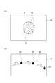
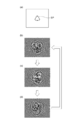
- FIG. 2 is an enlarged plan view showing (a) the laser beam La2 after phase modulation irradiated to the workpiece W via the condensing optical system 14, and (b) and (a) are partially enlarged. It is a figure.
- FIG. 3 is a diagram showing an example of the planar shape of the work area A (a) to (e).
- FIG. 4 is a block diagram showing a hardware configuration example of the control unit 18.
- 5A and 5B are a cross-sectional view showing a state in which laser light La2 is irradiated to a workpiece W including a plurality of regions Wa, Wb, and Wc whose materials are different from each other, and (b) a laser of the workpiece W. It is a top view which shows the irradiation surface.
- 6A and 6B are a cross-sectional view showing a state in which laser light La2 is irradiated to a workpiece W including a plurality of regions Wa, Wb, and Wc whose materials are different from each other, and (b) a laser of the workpiece W. It is a top view which shows the irradiation surface.
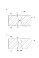
- FIG. 7A and 7B are a cross-sectional view showing a state in which laser light La2 is applied to a workpiece W including a plurality of regions Wd and We whose materials are different from each other, and FIGS. It is sectional drawing along the VIIb-VIIb line, VIIc-VIIc line and VIId-VIId line.
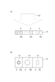
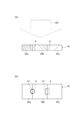
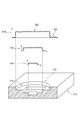
- FIG. 8 is a cross-sectional view showing (a) a state in which the laser beam La2 is irradiated to the work piece W, and (b) a cross-sectional view showing a hole Ha formed in the work piece W.
- FIG. 8 is a cross-sectional view showing (a) a state in which the laser beam La2 is irradiated to the work piece W, and (b) a cross-sectional view showing a hole Ha formed in the work piece W.
- FIG. 9 is a schematic example of arrangement of irradiation points SP in the cross section along each of the IXa-IXa line, the IXb-IXb line, and the IXc-IXc line shown in FIGS. 8 (a) to 8 (a). It is a figure which shows.
- FIG. 10 is a diagram schematically showing another arrangement example of the irradiation points SP in each of the cross sections (a) to (c).
- 11A and 11B are a cross-sectional view showing a state in which the laser beam La2 is irradiated to the workpiece W, and a cross-sectional view showing a hole Hb formed in the workpiece W.
- 12A and 12B are a cross-sectional view showing a state in which the laser beam La2 is irradiated to the workpiece W, and a cross-sectional view showing a hole Hc formed in the workpiece W.
- 13A and 13B are a cross-sectional view showing a state in which the laser beam La2 is irradiated to the workpiece W, and a cross-sectional view showing holes Hc and Hd formed in the workpiece W.
- 14A and 14B are a cross-sectional view showing how the laser beam La2 is irradiated to the workpiece W, and a cross-sectional view showing holes Hc, Hd, and He formed in the workpiece W. ..
- 15A and 15B are a diagram showing (a) a cross-sectional shape of a through hole Hf formed when the contours of two work areas A have a curvature, and (b) a figure showing a cross-sectional shape of a through hole Hf, and (b) the contour of one work area A has a curvature. It is a figure which shows the cross-sectional shape of the through hole Hg formed in the case.
- 16A and 16B are (a) a cross-sectional view showing a hole Hh formed by irradiation with a laser beam La2, (b) a plan view showing the shape of the hole Hh on one surface W1 of the workpiece W, and (c) a cover.
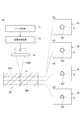
- FIG. 17 is a diagram conceptually showing a change in the shape of the work area A in the optical axis direction of the laser light La2 for forming the hole Hh, wherein (a) the laser light La2 is applied to the work piece W.
- the outline of the configuration for irradiating and the cross section of the workpiece W in the optical axis direction of the laser beam La2 are shown, and (b) to (e) in each plane located at different depths in the workpiece W.
- the shape of the work area A and a plurality of irradiation points SP in each surface are shown.
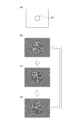
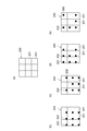
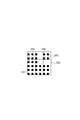
- FIG. 18 is a diagram showing an example of a hologram corresponding to the surface shown in FIG. 17 (b), showing (a) a plurality of irradiation points SP shown in FIG. 17 (b), and (b). Examples of holograms for realizing the plurality of irradiation points SP shown in (d) and (a) are shown.
- FIG. 19 is a diagram showing an example of a hologram corresponding to the surface shown in FIG. 17 (c), showing (a) a plurality of irradiation points SP shown in FIG. 17 (c), and (b). Examples of holograms for realizing the plurality of irradiation points SP shown in (d) and (a) are shown.
- FIG. 19 is a diagram showing an example of a hologram corresponding to the surface shown in FIG. 17 (c), showing (a) a plurality of irradiation points SP shown in FIG. 17 (c), and (b). Examples of holograms for realizing the plurality of i
- FIG. 20 is a diagram showing an example of a hologram corresponding to the surface shown in FIG. 17 (d), showing (a) a plurality of irradiation points SP shown in FIG. 17 (d), and (b). Examples of holograms for realizing the plurality of irradiation points SP shown in (d) and (a) are shown.
- 21 is a diagram showing an example of a hologram corresponding to the surface shown in FIG. 17 (e), showing (a) a plurality of irradiation points SP shown in FIG. 17 (e), and (b). Examples of holograms for realizing the plurality of irradiation points SP shown in (d) and (a) are shown.
- FIG. 17 (d) shows (a) a plurality of irradiation points SP shown in FIG. 17 (d)
- FIG. 17 (e) Examples of holograms for realizing the plurality of irradiation points SP shown in (d) and (a) are shown.
- FIG. 22 is a diagram showing how the irradiation point SP of the laser beam La2 is formed farther than the workpiece W.
- FIG. 23 is a flowchart showing a laser machining method according to an embodiment.
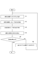
- FIG. 24 is a flowchart showing a case where the storage step S0 is performed before the control step S1.
- FIG. 25 is a diagram for explaining the laser processing method described in Patent Document 1.
- FIG. 26 is a diagram for explaining the laser processing methods described in Patent Documents (a) to (e).
- FIG. 27 is a diagram for explaining the laser processing method described in Patent Document 2.
- FIG. 1 is a block diagram showing a configuration of a laser processing apparatus 10 according to an embodiment.
- the laser processing apparatus 10 of the present embodiment includes a laser light source 11, a spatial light modulator 12, a dichroic mirror 13, a condensing optical system 14, a drive unit 15, and an observation light source 16. And an optical detector 17, and a control unit (PC or the like) 18.
- the laser light source 11 outputs a pulsed laser beam La1 having a time width of 1 picosecond or less (for example, several femtoseconds).
- the wavelength of the laser beam La1 output from the laser light source 11 is, for example, 250 nm or more and 2500 nm or less, and 1030 nm in one embodiment.
- the power of the laser beam La1 output from the laser light source 11 is, for example, 0.01 W or more and 1000 W or less, and 1 W in one embodiment.
- the laser light source 11 is, for example, a solid-state laser having a Yb: YAG crystal or a Yb: KGW crystal as a laser medium, or a Yb-added optical fiber laser excited by a semiconductor laser.
- the spatial light modulator 12 is optically coupled to the laser light source 11, and inputs the laser light La1 output from the laser light source 11.
- the optical coupling between the spatial light modulator 12 and the laser light source 11 is, for example, a spatial coupling.
- the spatial light modulator 12 has a plurality of pixels arranged in two dimensions, and by presenting a hologram to the plurality of pixels, the phase of the laser beam La1 is independently modulated for each pixel.
- the spatial light modulator 12 has, for example, a liquid crystal type configuration.
- the spatial light modulator 12 is a liquid crystal type
- individual voltages constituting a hologram are applied to a plurality of pixel electrodes arranged two-dimensionally.
- the magnitude of the electric field applied to the liquid crystal layer is controlled for each pixel electrode.
- the optical path length in the liquid crystal layer of each pixel changes according to the magnitude of the electric field. Therefore, the phase of the laser beam La1 can be modulated independently for each pixel.
- the spatial light modulator 12 may be a transmissive type or a reflective type. Further, the method of the spatial light modulator 12 is not limited to the liquid crystal type, and various types of spatial light modulators may be applied.
- the spatial light modulator 12 outputs the laser beam La2 after phase modulation by the hologram.
- the dichroic mirror 13 is an optical element that transmits light contained in a certain wavelength range and reflects light contained in another wavelength range. One surface of the dichroic mirror 13 is optically coupled to the spatial light modulator 12. The modulated laser light La2 that has reached the dichroic mirror 13 from the spatial light modulator 12 is reflected (or transmitted) by the dichroic mirror 13 and heads toward the workpiece W.
- the dichroic mirror 13 is, for example, a short-pass dichroic mirror.
- the laser light La2 passes through the condensing optical system 14 provided in the rear stage of the spatial light modulator 12 (more accurately, the rear stage of the dichroic mirror 13) and reaches the workpiece W.
- the condensing optical system 14 is, for example, a glass lens, which is optically coupled to the spatial light modulator 12 via a dichroic mirror 13.
- the optical coupling of the spatial light modulator 12, the dichroic mirror 13, and the condensing optical system 14 is, for example, a spatial coupling.
- the condensing optical system 14 is arranged on an optical path between the dichroic mirror 13 and the workpiece W.
- the drive unit 15 is electrically connected to each pixel electrode of the spatial light modulator 12, and provides each pixel electrode with a drive voltage Vd for presenting a hologram to the spatial light modulator 12.
- the drive unit 15 has a plurality of voltage generation circuits electrically connected to each pixel electrode.
- Each voltage generating circuit has an amplifier circuit including a transistor.
- the control unit 18 is electrically connected to the drive unit 15.
- the control unit 18 creates a hologram or reads it from a storage unit, and provides the two-dimensional data of the hologram to the drive unit 15.
- the drive unit 15 generates a drive signal, which is an analog signal based on the hologram, for each pixel.
- Each amplifier circuit of the drive unit 15 generates a drive voltage Vd by amplifying the drive signal.
- FIG. 2A is a plan view showing the laser beam La2 after phase modulation applied to the workpiece W via the condensing optical system 14. Further, FIG. 2B is an enlarged view of a part of FIG. 2A.
- the control unit 18 transmits the phase-modulated laser light La2 output from the spatial light modulator 12 to a plurality of irradiation points SP of the workpiece W by the condensing optical system 14. A hologram for condensing is generated, and the hologram is presented to the spatial light modulator 12.
- the plurality of irradiation points SP define the work area A in the work piece W. That is, the plurality of irradiation points SP are arranged at intervals on the closed virtual line B, and the work area A is defined by the virtual line B. Further, the control unit 18 causes the spatial light modulator 12 to sequentially present a plurality of holograms that change the position of each irradiation point SP along the virtual line B. As a result, as shown in FIG. 2B, each irradiation point SP moves discretely on the virtual line B.
- FIG. 3 is a diagram showing an example of the planar shape of the work area A.
- the work area A may be circular as shown in FIG. 3 (a) or elliptical as shown in FIG. 3 (b). Further, the work area A may be a triangle as shown in FIG. 3 (c), a quadrangle as shown in FIG. 3 (d), or an arbitrary region A as shown in FIG. 3 (e). It may be a polygon of.
- the control unit 18 makes the light intensities (unit: W / cm 2 and energy density (unit: J / cm 2 )) of at least two irradiation points SP included in the plurality of irradiation points SP independent of each other. To control. In one example, the control unit 18 independently controls the light intensities of all the irradiation points SP. The light intensity of each irradiation point SP is determined, for example, by the processing speed of the material of the workpiece W at each irradiation point SP and / or other factors.
- the light intensity is reduced to slow down the processing speed.
- the light intensity is increased to increase the processing speed.
- the processing speeds can be made uniform at a plurality of irradiation points SP.
- the light intensity can be reduced to minimize the region affected by heat.
- control unit 18 controls at least one of the light intensity and the irradiation time (in other words, the hologram presentation time) of the plurality of irradiation points SP according to the depth positions of the plurality of irradiation points SP in the workpiece W. do.
- the workpiece W to be processed in the present embodiment is composed of various substances such as glass, semiconductor, metal (steel material, non-ferrous metal, alloy, etc.) and composite material (carbon fiber reinforced plastic CFRP, etc.). Can be done.
- the observation light source 16 is a laser light source for irradiating the work piece W with the observation light Lb.
- the wavelength of the observation light Lb output from the observation light source 16 is different from the wavelengths of the laser beams La1 and La2.
- the wavelength of the observation light Lb is, for example, 800 nm or more and 980 nm or less, and in one example, it is 808 nm.
- the observation light source 16 is, for example, an Al (In) GaAs-based or InGaAsP-based semiconductor laser.
- the observation light source 16 is optically coupled to the other surface of the dichroic mirror 13.
- the observation light Lb that has reached the dichroic mirror 13 from the observation light source 16 passes through (or is reflected) through the dichroic mirror 13, heads toward the workpiece W with an optical path parallel to the laser beam La2, and is irradiated to the workpiece W. NS.
- the irradiation region of the observation light Lb in the workpiece W includes, for example, the workpiece region A shown in FIG. 2 (a).
- the reflected light Lc When a part of the observation light Lb reaches the workpiece W, it becomes reflected light Lc and is emitted from the workpiece W. Since the wavelength of the reflected light Lc is the same as the wavelength of the observation light Lb, the reflected light Lc passes through the dichroic mirror 13.
- the photodetector 17 is optically coupled to the other surface of the dichroic mirror 13 and detects the reflected light Lc via the dichroic mirror 13.
- the photodetector 17 is a two-dimensional image detector or a detector that acquires three-dimensional information.
- the photodetector 17 has, for example, an interference measurement optical system.
- the light detector 17 branches a part of the observation light Lb output from the observation light source 16 (or acquires the back light of the semiconductor laser as the observation light source 16), and obtains the back light of the observation light Lb.
- the interference light image is detected by causing a part (or back light) and the reflected light Lc to interfere with each other.
- the photodetector 17 is electrically connected to the control unit 18 and provides the control unit 18 with an electrical signal Sa regarding the detection result.
- An example of interference measurement used in this embodiment is described in Non-Patent Document 1 (F. Mezzapesa et al., Opt. Lett. Vol.36, pp.822-824 (2011)).
- the control unit 18 determines the processing state at each irradiation point SP based on the detection result from the photodetector 17. Then, the control unit 18 controls the hologram to be presented to the spatial light modulator 12 according to the processing state.
- the hologram control referred to here is, for example, control of the hologram presentation time, change to an appropriate hologram, and the like.
- FIG. 4 is a block diagram showing a hardware configuration example of the control unit 18.
- the control unit 18 includes a computer including hardware such as a CPU 181, a RAM 182, a ROM 183, an input device 184, a digital / analog converter 185, an auxiliary storage device 186, and a display output device 187. It is composed.
- the control unit 18 realizes the above-mentioned functions by operating these components by a program or the like stored in advance in the auxiliary storage device 186.
- 5 (a) and 6 (a) are cross-sectional views showing how the laser beam La2 is applied to the workpiece W including a plurality of regions Wa, Wb, and Wc whose materials are different from each other. It shows a cross section along the optical axis of the light La2 (in other words, along the thickness direction of the workpiece W).
- 5 (b) and 6 (b) are plan views showing the light-irradiated surface of the workpiece W.
- the regions Wa, Wb, and Wc are aligned in the direction intersecting the optical axis direction of the laser beam La2 (the thickness direction of the workpiece W), and the boundary line of the regions Wa, Wb, Wc is the light irradiation surface. Is exposed to.
- the processing speeds of the materials of the respective regions Wa, Wb, and Wc are different for the laser beam La2 having the same light intensity. Specifically, the processing speed of the region Wa is the slowest and the processing speed of the region Wc is the fastest with respect to the laser beam La2 having the same light intensity.
- three work areas A independent of each other are set for each of the areas Wa, Wb, and Wc. Then, a plurality of irradiation points SP defining one work area A are formed in the area Wa, a plurality of irradiation points SP defining another work area A are formed in the area Wb, and another work area is further formed. A plurality of irradiation points SP defining A are formed in the region Wc.
- a work area A straddling the areas Wa and Wb and another work area A straddling the areas Wb and Wc are set. Then, a plurality of irradiation points SP that define a part of one work area A are formed in the area Wa, and a plurality of irradiation points SP that define the rest of one work area A and the other work area A. A plurality of irradiation points SP that define a part of the above are formed in the region Wb, and a plurality of irradiation points SP that define the rest of the other work area A are formed in the region Wc.
- the control unit 18 controls the hologram presented to the spatial light modulator 12.
- the light intensity of each irradiation point SP is expressed by the shade of color. The darker the color, the higher the light intensity, and the lighter the color, the lower the light intensity.
- the processing speeds of the irradiation points SP in each region Wa, Wb, and Wc can be brought close to each other, and the processing depth can be made uniform.
- the relative relationship of the light intensity of each irradiation point SP is adjusted so that the processing speeds at each irradiation point SP are equal to each other.
- control unit 18 may detect the material at each irradiation point SP based on the detection result in the photodetector 17 shown in FIG. Since the reflectance with respect to the observation light Lb depends on the material, the material at each irradiation point SP can be known based on the intensity ratio of the observation light Lb and the reflected light Lc. Therefore, the boundaries of the regions Wa, Wb, and Wc can be detected.
- the control unit 18 may generate a hologram for setting the light intensity of each irradiation point SP independently of each other based on the detection result in the photodetector 17.
- data on the light intensity of each irradiation point SP according to the distribution of the regions Wa, Wb, and Wc may be stored in advance in a storage unit (for example, ROM 183 or auxiliary storage device 186 shown in FIG. 4).
- the control unit 18 can control the light intensity of each irradiation point SP based on the data.
- FIG. 7A is a cross-sectional view showing a state in which the laser beam La2 is irradiated to the workpiece W including a plurality of regions Wd and We whose materials are different from each other, and is along the optical axis of the laser beam La2. In other words, it shows a cross section (along the thickness direction of the workpiece W).
- 7 (b), (c), and (d) are cross-sectional views taken along the lines VIIb-VIIb, VIIc-VIIc, and VIId-VIId of FIG. 7 (a), respectively, and are the light of the laser beam La2.
- the cross section perpendicular to the axis is shown.
- the regions Wd and We are aligned in the optical axis direction of the laser beam La2, and the interface between the regions Wd and We is inclined with respect to the virtual plane perpendicular to the optical axis direction of the laser beam La2.
- the processing speeds of the materials of the respective regions Wd and We are different for the laser light La2 having the same light intensity.
- the processing speed of the region Wd is slower than the processing speed of the region We for the laser beam La2 having the same light intensity.
- the work area A is set for the work piece W, and a plurality of irradiation points SP defining the work area A are formed on the work piece W.
- the light intensity of each irradiation point SP is expressed by the shade of color. The darker the color, the higher the light intensity, and the lighter the color, the lower the light intensity.
- the control unit 18 controls the hologram presented to the spatial light modulator 12 so that the processing speed of each irradiation point SP in the region Wd becomes an arbitrary speed.
- the area A to be processed straddles the area Wd and the area We.
- the control unit 18 displays the hologram presented to the spatial light modulator 12 so that the light intensity of the irradiation point SP located in the region We becomes smaller than the light intensity of the irradiation point SP located in the region Wd. Control.
- the control unit 18 controls the hologram presented to the spatial light modulator 12 so that the processing speed of each irradiation point SP in the region We becomes an arbitrary speed.
- control unit 18 controls the hologram so that the light intensity of the irradiation point SP formed in the region Wd is larger than the light intensity of the irradiation point SP formed in the region We.
- the processing speeds of the irradiation points SP in the regions Wd and We are brought close to each other to make the processing depth uniform. Can be done.
- the light intensity of each irradiation point SP is adjusted so that the processing speed at each irradiation point SP becomes uniform in the depth direction.
- control unit 18 may detect a change in the material at each irradiation point SP based on the detection result in the photodetector 17 shown in FIG. Since the reflectance with respect to the observation light Lb depends on the material, the intensity ratio of the observation light Lb and the reflected light Lc changes when the material at each irradiation point SP changes. Therefore, the change of the material from the region Wd to the region We can be detected.
- the timing of changing the hologram for changing the light intensity of each irradiation point SP may be determined based on the detection result of the photodetector 17.
- data on the light intensity of each irradiation point SP according to the material distribution of the workpiece W may be stored in advance in a storage unit (for example, ROM 183 or auxiliary storage device 186 shown in FIG. 4).
- the control unit 18 can control the light intensity of each irradiation point SP based on the data.
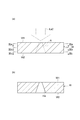
- FIG. 8A is a cross-sectional view showing how the laser beam La2 is irradiated to the workpiece W, and shows a cross section along the optical axis of the laser beam La2.
- FIG. 8B is a cross-sectional view showing a hole Ha formed in the workpiece W.
- the size of the work area A continuously changes in the optical axis direction of the laser light La2 from the light irradiation surface W1 of the work piece W to the surface W2 on the opposite side thereof.
- the continuous change in the size of the work area A means that the contour of the work area A does not have a step in the cross section along the optical axis direction of the laser beam La2.
- the holograms are sequentially switched as the processing progresses in the optical axis direction of the laser beam La2 (the depth direction of the workpiece W).
- Each hologram is formed by superimposing a hologram for realizing the size and shape of the processed region A in a plane intersecting the optical axis of the laser beam La2 and a hologram relating to the position of the plane in the optical axis direction.
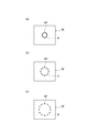
- FIG. 9 (a), (b), and (c) show the irradiation points SP in the cross section along the IXa-IXa line, the IXb-IXb line, and the IXc-IXc line shown in FIG. 8 (a).
- An arrangement example is schematically shown.
- the shape of the work area A in the cross section perpendicular to the optical axis direction of the laser beam La2 is circular.
- FIGS. 10A, 10B, and 10C schematically show another arrangement example of the irradiation points SP in each of the cross sections.
- the shape of the work area A in the cross section perpendicular to the optical axis direction of the laser beam La2 is an arbitrary complicated polygon.
- Each irradiation point SP shown in FIGS. 9 and 10 defines a work area A shown in FIG. 8 (a).
- the shape of the work area A in the cross section perpendicular to the optical axis direction of the laser beam La2 is not limited to the examples of FIGS. 9 and 10, and may be various other shapes.
- the control unit 18 makes the size of the work area A different from each other in the IXa-IXa cross section and the IXb-IXb cross section which are separated from each other in the direction of the optical axis.
- one of the IXa-IXa cross section and the IXb-IXb cross section corresponds to the first surface in the present embodiment, and the other corresponds to the second surface in the present embodiment.
- the control unit 18 makes the size of the work area A different from each other in the IXb-IXb cross section and the IXc-IXc cross section which are separated from each other in the direction of the optical axis.
- one of the IXb-IXb cross section and the IXc-IXc cross section corresponds to the first surface in the present embodiment, and the other corresponds to the second surface in the present embodiment.
- control unit 18 changes the position of each irradiation point SP along the virtual line B (see FIG. 2B) defining the work area A in each cross section.
- virtual line B see FIG. 2B
- each irradiation point SP moves discretely on the contour line of the work area A.
- the control unit 18 may determine the processing state at each irradiation point SP based on the detection result by the photodetector 17, and control the hologram presentation time in each of the above cross sections according to the processing state.
- the processing state is, for example, the processing speed (in other words, the progress of processing) at each irradiation point SP.
- the work area A may be set.
- it may be larger than the area of the work area A in the other cross section.
- control unit 18 presents the spatial light modulator 12 with a program for condensing the laser beam La2 at each irradiation point SP, so that the contour portion of the work area A is cut and the work area A is to be processed. It falls down from the object W.
- a hole Ha which is a through hole having a reverse taper shape with respect to the light irradiation surface W1, is formed in the workpiece W.
- the work piece W When the work piece W is made of a material such as glass that has light transmission to the laser light La2, the work piece W faces the light irradiation surface W1 from the side of the surface W2 opposite to the light irradiation surface W1 of the work piece W. It is recommended to process them sequentially.
- the light intensity is made larger than the processing threshold only at the condensing point of the laser light La2, and the light intensity is made smaller than the processing threshold in other regions (the region between the light irradiation surface W1 and the condensing point) in the workpiece W. By doing so, such processing is possible.
- the laser processing can be performed while the surplus (debris and debris) generated by the laser processing is dropped downward, the degree to which the surplus interferes with the irradiation of the laser beam La2 is reduced.
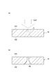
- FIG. 11A is a cross-sectional view showing how the laser beam La2 is irradiated to the workpiece W, and shows a cross section along the optical axis of the laser beam La2.
- FIG. 11B is a cross-sectional view showing a hole Hb formed in the workpiece W.
- the size of the work area A in the cross section perpendicular to the optical axis of the laser light La2 is on the opposite side of the light irradiation surface W1 of the work piece W.
- the laser beam La2 continuously changes in the optical axis direction over the surface W2.
- the size of the work area A in the cross section gradually increases as the distance from the light irradiation surface W1 increases.
- the contour of the work area A in the cross section along the optical axis of the laser beam La2 is not a straight line as shown in FIG. 8, but a shape having an inwardly convex curvature (for example, an arc shape). ).
- control unit 18 presents the spatial light modulator 12 with a program for condensing the laser beam La2 at each irradiation point SP, so that the contour portion of the work area A is cut and the work area A becomes It falls off from the workpiece W downward.
- a hole Hb which is a through hole having a reverse taper shape with respect to the light irradiation surface W1, is formed in the workpiece W.
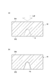
- 12 to 14 (a) are cross-sectional views showing how the laser beam La2 is irradiated to the workpiece W, and shows a cross section along the optical axis of the laser beam La2.
- 12 to 14 (b) are cross-sectional views showing holes Hc, Hd, and He formed in the workpiece W.
- a tapered work area A that reaches one surface W3 from the substantially central portion of the work W in the optical axis direction of the laser light La2 is set. ..
- the hole Hc shown in is formed.
- the hole Hc is a tapered (mortar-shaped) recess that reaches one surface W3 from the substantially central portion of the workpiece W.
- the workpiece W is turned upside down, and another tapered shape that reaches the other surface W4 from the substantially central portion of the workpiece W in the optical axis direction of the laser beam La2.
- the work area A of is set.
- the hole Hd shown in FIG. 13B is formed.
- the hole Hd is a tapered (mortar-shaped) recess that reaches the other surface W4 from the substantially central portion of the workpiece W.
- FIG. 14A yet another work area A connecting the hole Hc and the hole Hd is set. Then, by irradiating the laser beam La2 from the surface W3 or W4 and cutting the contour portion of the work area A in the same manner as in the example shown in FIG. 8, the hole He shown in FIG. 14B is formed. Form. In this way, a hole penetrating between one surface W3 and the other surface W4 of the workpiece W is formed.
- each work area A in the cross section along the optical axis of the laser beam La2 is linear, but at least one of them may have a curvature.
- FIG. 15A shows the cross-sectional shape of the through hole Hf formed when the two processed regions A have a curvature.
- the through hole Hf is formed by communicating the hole Hfa that reaches the surface W3 from the substantially central portion of the workpiece W and the hole Hfb that reaches the surface W4 from the substantially central portion of the workpiece W.
- the size of the hole Hfa in the cross section perpendicular to the optical axis of the laser beam La2 gradually increases as it approaches the surface W3 from the substantially central portion of the workpiece W.
- the size of the hole Hfb in the cross section perpendicular to the optical axis of the laser beam La2 gradually increases as it approaches the surface W4 from the substantially central portion of the workpiece W.
- the side surfaces of these holes Hfa and Hfb have an inwardly convex curvature in a cross section along the thickness direction of the workpiece W.
- FIG. 15B shows the cross-sectional shape of the through hole Hg formed when the contour of one work area A has a curvature.
- the through hole Hg is formed by communicating the hole Hga reaching the surface W3 from the substantially central portion of the workpiece W and the hole Hgb reaching the surface W4 from the substantially central portion of the workpiece W.
- the size of the hole Hga in the cross section perpendicular to the optical axis of the laser beam La2 gradually increases as it approaches the surface W3 from the substantially central portion of the workpiece W.
- the side surface of the hole Hga has an inwardly convex curvature in a cross section along the thickness direction of the workpiece W.
- the hole Hgb has a tapered shape (mortar shape) when viewed from the surface W4, similar to the hole Hc shown in FIG. 12 and the hole Hd shown in FIG.
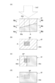
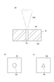
- FIG. 16A is a cross-sectional view showing the holes Hh formed by irradiation with the laser beam La2, and shows a cross section along the thickness direction of the workpiece W.
- FIG. 16B is a plan view showing the shape of the holes Hh on the light-irradiated surface W1 of the workpiece W
- FIG. 16C is a surface of the workpiece W opposite to the light-irradiated surface W1. It is a top view which shows the shape of the hole Hh in W2.
- the shape of the hole Hh on the light irradiation surface W1 (the first surface intersecting the optical axis of the laser beam La2) and the surface W2 on the side opposite to the light irradiation surface W1 (from the first surface to the optical axis).
- the shapes of the holes Hh on the second surface separated in the direction) are different from each other.
- the shape of the hole Hh on the light irradiation surface W1 is circular
- the shape of the hole Hh on the opposite surface W2 is an equilateral triangle.
- Such a hole Hh can be suitably formed by the control unit 18 making the shape of the work area A defined by a plurality of irradiation points in each of the light irradiation surface W1 and the surface W2 different from each other. ..
- the cross-sectional shape of the hole Hh perpendicular to the thickness direction of the workpiece W changes continuously along the thickness direction of the workpiece W.
- FIG. 17 is a diagram conceptually showing a change in the shape of the processed region A in the optical axis direction of the laser beam La2 for forming the hole Hh shown in FIG.
- FIG. 17A shows an outline of a configuration for irradiating the workpiece W with the laser beam La2 and a cross section of the workpiece W in the optical axis direction of the laser beam La2.
- 17 (b), (c), (d), and (e) show the shape of the work area A in each surface located at different depths in the work piece W, and a plurality of irradiations in each surface. It shows the point SP.
- the shape of the work area A on the light irradiation surface W1 is circular, but as shown in FIGS. 17C to 17E, the optical axis direction from the light irradiation surface W1.
- the shape of the work area A gradually approaches a triangle from a circle as the distance from the circle increases.
- the shape of the work area A on the surface W2 becomes a triangle.
- 18 to 21 are diagrams showing examples of holograms corresponding to each surface shown in FIGS. 17 (b) to 17 (e).
- 18 to 21 (a) show a plurality of irradiation points SP shown in FIGS. 17 (b) to 17 (e), respectively.
- 18 to 21 (b), (c), and (d) show an example of a hologram for realizing a plurality of irradiation points SP shown in each (a).
- the magnitude of the phase is indicated by the shade of color, and the darker the color, the smaller the phase (closer to 0 radian) and the lighter the color. The larger the phase (closer to 2 ⁇ radians).
- FIGS. 18 to 21, (b), (c), and (d) are irradiation points SP along the contour line of the work area A (virtual line B shown in FIG. 2). It shows multiple holograms for changing the position of.
- the control unit 18 periodically and repeatedly presents the holograms shown in (b), (c), and (d) to the spatial light modulator 12. Processing is performed while moving the position of each irradiation point SP along the contour line of the area A to be processed.
- the hologram to be presented next is called from the storage unit (for example, ROM 183 or auxiliary storage device 186 shown in FIG. 4), or the hologram to be presented next is presented based on the detection result in the photodetector 17. It takes time to generate by calculation.
- the storage unit for example, ROM 183 or auxiliary storage device 186 shown in FIG. 4
- the control unit 18 spatially light-modulates a hologram whose light intensity of the laser beam La2 is less than the processing threshold in any part of the workpiece W from the time when a certain hologram is erased to the time when another hologram is presented. Present to vessel 12. For example, as shown in FIG. 22, the control unit 18 may cause the spatial light modulator 12 to present a hologram that forms the irradiation point SP of the laser beam La2 farther than the workpiece W. .. As a result, it is possible to realize an operation equivalent to turning off the laser light source 11.
- the control unit 18 is also formed in the same manner as in each processing example shown in FIGS. 5 to 7.
- the light intensity of the plurality of irradiation points SP may be controlled independently for each irradiation point SP.
- the control unit 18 may independently control the light intensity of the irradiation points SP in each surface arranged in the optical axis direction for each surface.
- the light intensity of the irradiation point SP in the IXa-IXa cross section, the IXb-IXb cross section, and the IXc-IXc cross section depends on the material (or processing speed) in each cross section. It may be set independently for each cross section. Further, the irradiation time for each cross section may be set independently.
- FIG. 23 is a flowchart showing a laser processing method according to the present embodiment.
- This laser processing method can be performed using the laser processing apparatus 10 described above.
- a control step S1 a hologram that modulates the phase of light in each of a plurality of two-dimensionally arranged pixels is presented to the spatial light modulator 12.
- the light modulation step S2 the laser light La1 output from the laser light source 11 is input to the spatial light modulator 12, and the phase modulation of the laser light La1 is performed by the hologram.
- the focusing step S3 the phase-modulated laser beam La2 is focused by using the focusing optical system 14.
- the spatial light modulator 12 presents a hologram in which the phase-modulated laser light La2 is focused on a plurality of irradiation points SP of the workpiece W by the focusing step S3.
- a plurality of irradiation points SP are formed on the workpiece W, and processing (melting, crack generation, cutting, etc.) of the workpiece W proceeds at each irradiation point SP.
- the light detection step S4 the work piece W is irradiated with the observation light Lb having a wavelength different from the wavelength of the laser light La2, and the observation light (reflected light Lc) reflected by the work piece W is detected.
- steps S1 to S4 are repeated while changing the hologram.
- the control step S1 as shown in FIG. 2, a plurality of holograms that change the position of each irradiation point SP along the virtual line B defining the work area A are sequentially presented to the spatial light modulator 12. Further, when the difference between the set target value of the light intensity of the irradiation point SP and the detection result of the observation light is larger than the target error (step S5: NO), the hologram may be corrected (step S6).
- the light intensities of the plurality of irradiation point SPs are independently controlled for each irradiation point SP.
- the shape of the work area A defined by the plurality of irradiation points SP is formed for each of a plurality of surfaces that intersect the optical axis of the laser light La2. Make it different.
- the light intensities of the plurality of irradiation points SP are independently controlled for each irradiation point SP, and the shape of the processed region A defined by the plurality of irradiation points SP is controlled by the laser light La2. Different for each of the multiple surfaces that intersect the optical axis.
- the control step S1 When the light intensity is independently controlled for each irradiation point SP, in the control step S1, the change in the material at each irradiation point SP is detected based on the detection result in the previous light detection step S4, and the light of each irradiation point SP is detected. The strength is changed according to the change of the material.
- the storage step S0 is performed before the control step S1, and in the storage step S0, data regarding the light intensity of each irradiation point SP according to the material distribution of the workpiece W is stored in the storage unit. (For example, ROM 183 or auxiliary storage device 186 shown in FIG. 4) is stored in advance. Then, in the control step S1, the light intensity of each irradiation point SP is controlled based on the data. Further, when the difference between the set target value of the light intensity of the irradiation point SP and the detection result of the observation light is larger than the target error (step S5: NO), the hologram may be corrected (step S6).
- the shape of the work area A is different for each of a plurality of surfaces intersecting with the optical axis of the laser light La2, as shown in FIGS. 8 to 15, the shape of the work area A is changed to the laser light La2. It is also possible to change continuously in the direction of the optical axis of.
- the workpiece W has light transmission to the laser beam La2, as shown in FIGS. 8 to 15, the workpiece W is to be processed on a surface far from the light irradiation surface W1. It is also possible to make the area of the region A larger than the area of the work region A on the surface that is close to the light irradiation surface W1.
- the hologram is changed in the control step S1, the light intensity of the laser beam La2 is processed at any part of the workpiece W from the time when a certain hologram is erased to the time when another hologram is presented.
- the hologram to be less than the threshold value is presented to the spatial light modulator 12.
- At least one of the shape and size of the work area A is different for each surface in at least two surfaces separated from each other in the optical axis direction.
- the shape of the cross section perpendicular to the optical axis direction can be freely set. It is possible to perform more complicated processing.
- the adjustment of the light intensity of each irradiation point SP, the on / off of each irradiation point SP, and the movement of each irradiation point SP along the virtual line B can be performed without using the mechanism unit at all. It can be realized. Therefore, the apparatus configuration of the laser processing apparatus 10 can be greatly simplified, and the processing can be performed at high speed and with high accuracy.
- the workpiece W has light transmission to the laser beam La2 after phase modulation, and the work area A on the surface where the workpiece W is far from the light irradiation surface W1.
- the area may be larger than the area of the work area A on the surface having a short distance.
- complicated processing such as formation of a reverse-tapered hole whose hole diameter increases as the distance from the light-irradiated surface W1 of the workpiece W increases can be easily performed.
- control unit 18 in control step S1) may continuously change at least one of the shape and size of the area A to be processed in the optical axis direction of the laser beam La2. In this case, it is possible to easily process a hole or the like in which the shape of the cross section perpendicular to the optical axis direction is smoothly deformed in the optical axis direction.
- the control unit 18 positions each irradiation point SP along the virtual line B defining the work area A on each of the plurality of surfaces arranged in the optical axis direction.
- a plurality of holograms to be changed may be sequentially presented to the spatial light modulator 12.
- the output power required for the laser light source 11 can be reduced as compared with the case where the laser light La2 is irradiated at once by a single hologram while giving sufficient light intensity to each irradiation point SP, and the laser light source can be reduced. It can contribute to the miniaturization of 11.
- the laser processing apparatus 10 is an observation light source 16 that irradiates the workpiece W with the observation light Lb, and a photodetector that detects the reflected light Lc that is the observation light reflected by the workpiece W. 17 and may be provided. Further, the laser processing method may further include a light detection step S4 in which the work piece W is irradiated with the observation light Lb and the reflected light Lc from the work piece W is detected.
- control unit 18 determines the processing state at each irradiation point SP based on the detection result by the photodetector 17 (light detection step S4), and determines the processing state of the hologram presentation time for each surface. It may be controlled according to. Alternatively, the control unit 18 (in control step S1) detects a change in the material at each irradiation point SP based on the detection result by the photodetector 17, and changes the light intensity of each irradiation point SP according to the change in the material. You may. In these cases, the processing accuracy can be further improved.
- control unit 18 may control the light intensities of at least two irradiation point SPs included in the plurality of irradiation points SP in each plane independently of each other.
- the laser light has an appropriate light intensity at each irradiation point SP corresponding to each part.
- La2 can be irradiated. Therefore, it is possible to easily process the workpiece W made of two or more kinds of materials into a complicated shape.
- control unit 18 may independently control the light intensity of the irradiation point SP in at least two planes for each plane.
- the laser light La2 is irradiated with an appropriate light intensity according to the material of each surface. be able to.
- the control unit 18 determines the light intensity of the laser beam La2 from the time when one hologram is erased to the time when another hologram is presented.
- the spatial light modulator 12 may be presented with a hologram that is less than the processing threshold at any part of the workpiece W.
- the mechanical shutter itself and the high voltage device required to operate the mechanical shutter are not required, so that the laser processing device is not required. It is possible to simplify the configuration of the 10 and contribute to the miniaturization and cost reduction of the laser processing apparatus 10.
- the laser processing apparatus 10 includes a storage unit that stores in advance data regarding the light intensity of each irradiation point SP according to the material distribution of the workpiece W, and the control unit 18 has each irradiation point.
- the light intensity of the SP may be controlled based on the data.
- the laser processing method includes, before the control step S1, a storage step S0 in which data relating to the light intensity of each irradiation point SP according to the material distribution of the workpiece W is stored in advance, and in the control step S1, each The light intensity of the irradiation point SP may be controlled based on the data. In these cases, the light intensity required for each irradiation point SP can be quickly obtained, so that the hologram change time can be shortened.
- FIG. 25 is a diagram for explaining the laser processing method described in Patent Document 1.
- This laser processing method is a method of processing a workpiece (workpiece) 110 having a processing surface 112 by laser ablation, and forms a three-dimensional geometric shape 114 in the workpiece 110.
- FIG. 25 shows three different beam profiles 116, 118 and 120.
- the vertical axis represents the light intensity and the horizontal axis represents the position.
- the laser beam has a pattern of irradiated areas 122 and non-irradiated areas 124 at the treated surface 112.
- the light intensity exceeds the ablation threshold.
- the non-irradiated region 124 the light intensity is below the dissolution threshold of the material of the workpiece 110.
- the beam profiles 116, 118, 120 differ from each other in terms of their diameter, equivalent diameter, and / or geometry. That is, the beam profiles 116, 118, 120 have smaller diameters or equivalent diameters in this order. Further, a partially cutaway cross section of the workpiece 110 shows that these beam profiles 116, 118, 120 may have different geometric shapes from each other. Therefore, the workpiece 110 has a stepped geometric shape.
- the laser light La2 is focused on a plurality of irradiation points SP for processing, so that the output power of the laser light source 11 is relatively high. It can be small and can contribute to the miniaturization of the laser light source 11. Further, for example, it is easy to process a complicated shape such as a reverse-tapered hole Ha as shown in FIG. 8 or a hole Hh shown in FIG.
- the light intensity and the irradiation time are independently controlled for each irradiation point SP, the light intensity and the irradiation time can be easily adjusted according to the properties of each material even when a plurality of materials are mixed in the work area. Can be set. Further, optical components such as a ⁇ / 2 plate and a polarizing beam splitter for adjusting the light intensity are not required, and the configuration of the laser processing apparatus can be further simplified.
- 26 and 27 are diagrams for explaining the laser processing method described in Patent Document 2.
- a plurality of image reproduction hologram data are prepared and laser processing is performed.
- the surface to be processed 200 is divided into a plurality of cells 201, one irradiation point 202 is associated with one cell 201, and each cell 201 is associated with one irradiation point 202.
- it is freely selected whether or not to form the irradiation point 202.
- the position movement hologram data is superimposed on this image reproduction hologram data. Then, while changing the position movement hologram data, the discrete point images shown in FIGS. 26 (b) to 26 (e) are processed and formed on the surface to be processed 200 to form the processed shape 203 having a complicated shape shown in FIG. 27. obtain.
- the light intensity and the irradiation time are independently controlled for each irradiation point SP, so that a plurality of materials are mixed in the work area. Even in this case, the light intensity and the irradiation time can be easily set according to the properties of each material.
- the laser processing apparatus and laser processing method are not limited to the above-described embodiments and configuration examples, and various other modifications are possible.
- the light intensity is controlled independently for each irradiation point SP to process the light intensity according to the properties of each material. Said that it would be possible.
- the removal rate of the work W is determined by controlling the light intensity independently for each irradiation point SP. The amount of removal) can be controlled independently for each portion of the work area A, and a more complicated shape can be realized.
- the case where the light intensities of the plurality of irradiation points SP are controlled independently is illustrated, but when it is not always necessary to control all the irradiation points SP independently, a plurality of irradiations are performed.
- the light intensities of at least two irradiation point SPs among the point SPs may be controlled independently of each other. Even in that case, the effect of the above embodiment can be achieved.
- the laser processing apparatus inputs the laser light output from the laser light source, presents a hologram that modulates the phase of the laser light in each of a plurality of pixels arranged in two dimensions, and after phase-modulating the hologram.
- the spatial light modulator that outputs the laser light of the above, the condensing optical system provided after the spatial light modulator, and the phase-modulated laser light output from the spatial light modulator are processed by the condensing optical system.
- a control unit for presenting a hologram focused on a plurality of irradiation points of an object to a spatial light modulator is provided, and the control unit intersects the optical axis of the phase-modulated laser light applied to the workpiece.
- An area to be processed defined by a plurality of irradiation points in one plane and a second plane which intersects the optical axis and is separated from the first surface in the direction of the optical axis are defined by a plurality of irradiation points. At least one of the shape and size of the work area to be processed is different from each other.
- the laser processing method includes a control step of presenting a hologram that modulates the phase of light in each of a plurality of pixels arranged in two dimensions to a spatial light modulator, and spatial light modulation of the laser light output from the laser light source.
- the optical modulation step of inputting the light into the device and performing phase modulation of the laser light by the hologram and the focusing step of condensing the laser light after the phase modulation are repeated, and the laser light after the phase modulation is collected in the control step.
- the work piece has light transmission to the laser light after phase modulation, and one of the first and second surfaces is farther from the light irradiation surface of the work piece.
- the area of the work area on the surface may be larger than the area of the work area on the other surface.
- the workpiece has light transmission to the laser light after phase modulation, and in the control step, the distance from the light irradiation surface of the workpiece among the first and second surfaces.
- the area of the work area on one surface that is far away may be larger than the area of the work area on the other surface.
- control unit may be configured to continuously change at least one of the shape and size of the area to be processed in the direction of the optical axis.
- At least one of the shape and size of the area to be machined may be continuously changed in the direction of the optical axis in the control step.
- control unit converts a plurality of holograms that change the position of each irradiation point along the virtual line defining the area to be processed into the spatial light modulator on each of the first and second surfaces. It may be configured to be presented sequentially.
- a plurality of holograms that change the position of each irradiation point along a virtual line defining a work area on each of the first and second surfaces are applied to the spatial light modulator. It may be configured to be presented sequentially.
- the above laser processing apparatus further includes an observation light source that irradiates the work piece with observation light and a photodetector that detects the observation light reflected by the work piece, and the control unit detects by the photodetector.
- the processing state at each irradiation point may be determined based on the result, and the presentation time of the hologram on the first and second surfaces may be controlled according to the processing state.
- the above laser processing method further includes a light detection step of irradiating the work piece with observation light and detecting the observation light reflected by the work piece, and in the control step, each irradiation is based on the detection result in the light detection step.
- the processing state at the point may be determined, and the presentation time of the hologram on the first and second surfaces may be controlled according to the processing state.
- the processing accuracy can be further improved.
- control unit may be configured to independently control the light intensities of at least two irradiation points included in the plurality of irradiation points in each plane.
- the light intensities of at least two irradiation points included in the plurality of irradiation points in each plane may be controlled independently of each other.
- the light intensity is appropriate at each irradiation point corresponding to each part. It can irradiate laser light. Therefore, it is possible to easily process a workpiece made of two or more kinds of materials into a complicated shape. Further, even when the work area is made of a single material, the removal rate (removal amount) of the work piece can be set for each part of the work area by independently controlling the light intensity for each irradiation point. Can be controlled independently, and more complicated shapes can be realized.
- control unit may be configured to independently control the light intensities of the plurality of irradiation points in the first plane and the light intensities of the plurality of irradiation points in the second plane. good.
- the light intensities of the plurality of irradiation points in the first plane and the light intensities of the plurality of irradiation points in the second plane may be controlled independently of each other. good.
- the control unit when changing the hologram, applies the light intensity of the laser light to any part of the workpiece from the time when one hologram is erased to the time when another hologram is presented.
- the hologram may be presented to the spatial light modulator so that the hologram is less than the processing threshold.
- the hologram when the hologram is changed in the control step, the light intensity of the laser light is applied to any part of the workpiece from the time when one hologram is erased to the time when another hologram is presented.
- the hologram may be presented to the spatial light modulator so that the hologram is less than the processing threshold.
- the configuration of the laser processing apparatus can be simplified as compared with the case where the laser beam is blocked by a mechanical means such as a shutter.
- the present invention is a laser processing apparatus and a laser processing method capable of performing more complicated processing in a configuration in which a plurality of irradiation points are simultaneously focused and irradiated by phase-modulating a laser beam using a spatial light modulator. It is available as.
Landscapes
- Physics & Mathematics (AREA)
- Optics & Photonics (AREA)
- Engineering & Computer Science (AREA)
- Plasma & Fusion (AREA)
- Mechanical Engineering (AREA)
- General Physics & Mathematics (AREA)
- Chemical & Material Sciences (AREA)
- Nonlinear Science (AREA)
- Chemical Kinetics & Catalysis (AREA)
- General Chemical & Material Sciences (AREA)
- Oil, Petroleum & Natural Gas (AREA)
- Crystallography & Structural Chemistry (AREA)
- Laser Beam Processing (AREA)
- Optical Modulation, Optical Deflection, Nonlinear Optics, Optical Demodulation, Optical Logic Elements (AREA)
Abstract
レーザ加工装置10は、レーザ光源11から出力されたレーザ光La1を入力し、ホログラムにより位相変調した後のレーザ光La2を出力する空間光変調器12と、空間光変調器12から出力された位相変調後のレーザ光La2を集光光学系14により被加工物Wの複数の照射点SPに集光させるホログラムを空間光変調器12に呈示させる制御部18とを備える。制御部18は、被加工物Wに照射されるレーザ光La2の光軸と交差する第1の面内において複数の照射点SPにより画成される被加工領域Aと、光軸と交差し第1の面から光軸の方向に離れている第2の面内において複数の照射点SPにより画成される被加工領域Aとの、形状及び大きさのうち少なくとも一方を互いに異ならせる。これにより、空間光変調器を用いてレーザ光を位相変調することにより複数の照射点に同時に集光照射を行うレーザ加工装置において、より複雑な加工を行うことが可能となる。
Description
本開示は、レーザ加工装置及びレーザ加工方法に関するものである。
特許文献1には、レーザアブレーションによるレーザ加工方法に関する技術が開示されている。このレーザ加工方法では、ビームプロファイルを可変とするビーム成形装置を用い、被加工物の厚さ方向に並ぶ複数の処理面のそれぞれに対し、互いに異なる幾何学形状のビームプロファイルを有するレーザビームを照射する。
特許文献2には、レーザ加工装置及びレーザ加工方法に関する技術が開示されている。このレーザ加工方法では、レーザ光源から出射されたレーザ光を空間位相変調素子により位相変調して結像光学系に導き、該結像光学系によりレーザ光を被加工物に照射して、該被加工物を加工する。空間位相変調素子に入力される入力データとして、被加工物の加工形状を再生する像再生ホログラムデータと、所定加工位置に像再生を行う位置移動ホログラムデータとからなる合成データを用いる。そして、該合成データを順次変化させながら、被加工物にレーザ加工を行う。
F. Mezzapesa et al., "High-resolution monitoring of the hole depth during ultrafast laser ablation drilling by diode laser self-mixing interferometry", Opt. Lett. Vol.36, pp.822-824 (2011)
レーザ光源から出力されたレーザ光を集光光学系により集光して加工対象物に照射することにより該加工対象物を加工することができる。単にレンズを用いてレーザ光を集光する場合、レーザ光の集光位置を走査することによって、加工対象物を所望の形状に加工することができる。しかしながら、この場合には加工に長時間を要する。
加工時間を短縮するために、例えば複数の照射点に対しレーザ光を同時に集光照射して多点同時加工を行うことが考えられる。そのための手法として、位相変調型の空間光変調器にホログラムを呈示して、単一のレーザ光源から出力されたレーザ光を空間光変調器により位相変調し、その位相変調されたレーザ光を集光光学系により複数の照射点に同時に集光照射する手法がある。この場合、空間光変調器に呈示されるホログラムは、集光光学系により複数の照射点にレーザ光が集光されるような位相変調分布を有する。
上記のような手法においては、照射点の位置を自在に制御し、より複雑な加工を行うことが望まれている。
本発明は、空間光変調器を用いてレーザ光を位相変調することにより複数の照射点に同時に集光照射を行うレーザ加工装置及びレーザ加工方法において、より複雑な加工を行うことを目的とする。
本発明の実施形態は、レーザ加工装置である。レーザ加工装置は、レーザ光源から出力されたレーザ光を入力し、二次元配列された複数の画素それぞれにおいてレーザ光の位相を変調するホログラムを呈示して、ホログラムにより位相変調した後のレーザ光を出力する空間光変調器と、空間光変調器の後段に設けられた集光光学系と、空間光変調器から出力された位相変調後のレーザ光を集光光学系により被加工物の複数の照射点に集光させるホログラムを空間光変調器に呈示させる制御部と、を備え、制御部は、被加工物に照射される位相変調後のレーザ光の光軸と交差する第1の面内において複数の照射点により画成される被加工領域と、光軸と交差し第1の面から光軸の方向に離れた第2の面内において複数の照射点により画成される被加工領域との、形状及び大きさのうち少なくとも一方を互いに異ならせる。
本発明の実施形態は、レーザ加工方法である。レーザ加工方法は、二次元配列された複数の画素それぞれにおいて光の位相を変調するホログラムを空間光変調器に呈示させる制御ステップと、レーザ光源から出力されたレーザ光を空間光変調器に入力し、ホログラムによりレーザ光の位相変調を行う光変調ステップと、位相変調後のレーザ光を集光する集光ステップと、を繰り返し行い、制御ステップにおいて、位相変調後のレーザ光を集光ステップにより被加工物の複数の照射点に集光させるホログラムを空間光変調器に呈示させ、被加工物に照射される位相変調後のレーザ光の光軸と交差する第1の面内において複数の照射点により画成される被加工領域と、光軸と交差し第1の面から光軸の方向に離れた第2の面内において複数の照射点により画成される被加工領域との、形状及び大きさのうち少なくとも一方を互いに異ならせる。
上記のレーザ加工装置及びレーザ加工方法では、互いに光軸方向に離れている第1及び第2の面内において複数の照射点により画成される被加工領域の、形状及び大きさのうち少なくとも一方が互いに異なる。このように、光軸方向に離れた複数の面毎に被加工領域の形状及び/又は大きさを変化させることにより、光軸方向に垂直な断面の形状を自在に設定するような、従来より複雑な加工を行うことが可能となる。
本発明の実施形態によれば、空間光変調器を用いてレーザ光を位相変調することにより複数の照射点に同時に集光照射を行うレーザ加工装置及びレーザ加工方法において、より複雑な加工を行うことが可能となる。
以下、添付図面を参照しながら、レーザ加工装置及びレーザ加工方法の実施の形態を詳細に説明する。なお、図面の説明において同一の要素には同一の符号を付し、重複する説明を省略する。また、本発明はこれらの例示に限定されるものではない。
図1は、一実施形態に係るレーザ加工装置10の構成を示すブロック図である。図1に示すように、本実施形態のレーザ加工装置10は、レーザ光源11と、空間光変調器12と、ダイクロイックミラー13と、集光光学系14と、駆動部15と、観察用光源16と、光検出器17と、制御部(PC等)18とを備える。
レーザ光源11は、1ピコ秒以下(例えば数フェムト秒)の時間幅を有するパルス状のレーザ光La1を出力する。レーザ光源11から出力されるレーザ光La1の波長は、例えば250nm以上2500nm以下であって、一実施例では1030nmである。また、レーザ光源11から出力されるレーザ光La1のパワーは、例えば0.01W以上1000W以下であって、一実施例では1Wである。レーザ光源11は、例えばYb:YAG結晶やYb:KGW結晶をレーザ媒質として有する固体レーザ、又は半導体レーザにより励起されたYb添加光ファイバーレーザーである。
空間光変調器12は、レーザ光源11と光学的に結合されており、レーザ光源11から出力されたレーザ光La1を入力する。空間光変調器12とレーザ光源11との光学的な結合は、例えば空間的な結合である。空間光変調器12は、二次元配列された複数の画素を有し、該複数の画素にホログラムを呈示することにより、各画素ごとに独立してレーザ光La1の位相を変調する。
空間光変調器12は、例えば液晶型の構成を有する。空間光変調器12が液晶型である場合、二次元配列された複数の画素電極に対し、ホログラムを構成する個別の電圧を印加する。これにより、液晶層にかかる電界の大きさを画素電極ごとに制御する。各画素の液晶層における光路長は、電界の大きさに応じて変化する。故に、各画素ごとに独立してレーザ光La1の位相を変調することができる。
空間光変調器12は、透過型であってもよく、反射型であってもよい。また、空間光変調器12の方式は液晶型に限られず、種々の方式の空間光変調器を適用してよい。空間光変調器12は、ホログラムにより位相変調した後のレーザ光La2を出力する。
ダイクロイックミラー13は、或る波長範囲に含まれる光を透過し、別の波長範囲に含まれる光を反射する光学素子である。ダイクロイックミラー13の一方の面は、空間光変調器12と光学的に結合されている。空間光変調器12からダイクロイックミラー13に到達した変調後のレーザ光La2は、ダイクロイックミラー13により反射(または透過)し、被加工物Wへ向かう。ダイクロイックミラー13は、例えばショートパスダイクロイックミラーである。
レーザ光La2は、空間光変調器12の後段(より正確にはダイクロイックミラー13の後段)に設けられた集光光学系14を通過して、被加工物Wに達する。集光光学系14は、例えばガラス製のレンズであって、ダイクロイックミラー13を介して空間光変調器12と光学的に結合されている。空間光変調器12、ダイクロイックミラー13及び集光光学系14の光学的な結合は、例えば空間的な結合である。集光光学系14は、ダイクロイックミラー13と被加工物Wとの間の光路上に配置されている。
駆動部15は、空間光変調器12の各画素電極と電気的に接続されており、ホログラムを空間光変調器12に呈示させるための駆動電圧Vdを各画素電極に提供する。駆動部15は、各画素電極に電気的に接続された複数の電圧発生回路を有する。各電圧発生回路は、トランジスタを含む増幅回路を有する。
制御部18は、駆動部15と電気的に接続されている。制御部18は、ホログラムを作成するか又は記憶部から読み出し、ホログラムの2次元データを駆動部15に提供する。駆動部15は、該ホログラムに基づくアナログ信号である駆動信号を画素毎に生成する。駆動部15の各増幅回路は、駆動信号を増幅することにより駆動電圧Vdを生成する。
図2(a)は、集光光学系14を介して被加工物Wに照射された位相変調後のレーザ光La2を示す平面図である。また、図2(b)は、図2(a)の一部を拡大して示す図である。図2(a)に示すように、制御部18は、空間光変調器12から出力された位相変調後のレーザ光La2を、集光光学系14により被加工物Wの複数の照射点SPに集光させるためのホログラムを生成し、該ホログラムを空間光変調器12に呈示させる。
複数の照射点SPは、被加工物Wにおける被加工領域Aを画成する。すなわち、複数の照射点SPは、閉じた仮想線B上において間隔をあけて並んでおり、被加工領域Aは、仮想線Bによって画定される。また、制御部18は、仮想線Bに沿って各照射点SPの位置を変更する複数のホログラムを、空間光変調器12に順次呈示させる。これにより、図2(b)に示すように、各照射点SPは仮想線B上を離散的に移動する。
複数の照射点SPによって画成される被加工領域Aの平面形状(レーザ光La2の光軸に垂直な平面内での形状)は、加工の目的等に応じて様々に設定される。図3は、被加工領域Aの平面形状の例を示す図である。被加工領域Aは、図3(a)に示すように円形であってもよく、図3(b)に示すように楕円形であってもよい。また、被加工領域Aは、図3(c)に示すように三角形であってもよく、図3(d)に示すように四角形であってもよく、図3(e)に示すように任意の多角形であってもよい。
制御部18は、複数の照射点SPに含まれる少なくとも2つの照射点SPの光強度(単位:W/cm2、エネルギー密度(単位:J/cm2)と言い換えてもよい)を、互いに独立して制御する。一例では、制御部18は、全ての照射点SPの光強度をそれぞれ独立して制御する。各照射点SPの光強度は、例えば各照射点SPにおける被加工物Wの材質の加工速度及び/または他の要因によって決定される。
例えば、レーザ光La2に対して加工速度が速い(すなわち加工容易な)材質の場合は、光強度を小さくして加工速度を遅くする。また、レーザ光La2に対して加工速度が遅い(すなわち加工が難しい)材質の場合は、光強度を大きくして加工速度を速める。こうして、加工速度が異なる材質が被加工物Wの光照射表面内又は断面内に混在している場合であっても、複数の照射点SPにおいて加工速度を揃えることができる。或いは、熱による影響が大きい材質に対しては、光強度を小さくして熱の影響が及ぶ領域を最小化することができる。
また、制御部18は、複数の照射点SPの光強度及び照射時間(言い換えると、ホログラム呈示時間)のうち少なくとも一方を、被加工物Wにおける複数の照射点SPの深さ位置に応じて制御する。
例えば、被加工物Wの光照射表面を加工する場合に比べて深い部分を加工する時には、その直前のレーザ光La2の照射の際に残存したデブリ等がレーザ光La2の照射を妨げるので、加工速度が低下する。したがって、被加工物Wにおける深い部分ほど複数の照射点SPの光強度を大きくし、及び/又は照射時間を長くすることにより、加工速度及び加工品質が向上する。また、被加工物Wが、互いに材質が異なる複数の層から構成されている場合(例えば半導体やプリント配線基板など)には、ホログラムの変更周期や呈示時間を制御することにより、各層に適した条件でレーザ加工を行うことができる。
なお、本実施形態において加工対象となる被加工物Wは、例えば、ガラス、半導体、金属(鉄鋼材料、非鉄金属、合金など)、複合材(炭素繊維強化プラスチックCFRPなど)といった種々の物質により構成され得る。
再び図1を参照する。観察用光源16は、観察光Lbを被加工物Wに照射するためのレーザ光源である。観察用光源16から出力される観察光Lbの波長は、レーザ光La1及びLa2の波長とは異なる。観察光Lbの波長は、例えば800nm以上980nm以下であって、一実施例では808nmである。観察用光源16は、例えばAl(In)GaAs系、又はInGaAsP系の半導体レーザである。
観察用光源16は、ダイクロイックミラー13の他方の面と光学的に結合されている。観察用光源16からダイクロイックミラー13に到達した観察光Lbは、ダイクロイックミラー13を透過(または反射)し、レーザ光La2と平行な光路でもって被加工物Wへ向かい、被加工物Wに照射される。
なお、図では観察光Lbの光軸とレーザ光La2の光軸とが並んで描かれているが、観察光Lbの光軸とレーザ光La2の光軸とは互いに一致していてもよい。被加工物Wにおける観察光Lbの照射領域は、例えば、図2(a)に示された被加工領域Aを内含する。
観察光Lbの一部は、被加工物Wに到達すると反射光Lcとなり、被加工物Wから出射する。反射光Lcの波長は観察光Lbの波長と同じであるため、反射光Lcはダイクロイックミラー13を透過する。光検出器17は、ダイクロイックミラー13の他方の面と光学的に結合されており、反射光Lcを、ダイクロイックミラー13を介して検出する。
光検出器17は、2次元画像検出器や3次元情報を取得する検出器である。後者の場合、光検出器17は例えば干渉計測光学系を有する。その場合、光検出器17は、観察用光源16から出力された観察光Lbの一部を分岐して(或いは観察用光源16としての半導体レーザの背面光を)取得し、該観察光Lbの一部(若しくは背面光)と反射光Lcとを互いに干渉させることにより干渉光像を検出する。
光検出器17は、制御部18と電気的に接続されており、検出結果に関する電気的な信号Saを制御部18に提供する。なお、本実施形態において用いられる干渉計測の例に関しては、非特許文献1(F. Mezzapesa et al., Opt. Lett. Vol.36, pp.822-824 (2011))に記載されている。
制御部18は、光検出器17からの検出結果に基づいて、各照射点SPにおける加工状態を判断する。そして、制御部18は、空間光変調器12に呈示させるホログラムを、加工状態に応じて制御する。ここでいうホログラムの制御とは、例えばホログラムの呈示時間の制御、適切なホログラムへの変更等である。
図4は、制御部18のハードウェア構成例を示すブロック図である。図4に示すように、制御部18は、CPU181、RAM182、ROM183、入力装置184、ディジタル/アナログ変換器185、補助記憶装置186、及びディスプレイ出力装置187等のハードウェアを備えるコンピュータを含むものとして構成される。制御部18は、補助記憶装置186に予め記憶されたプログラム等によりこれらの構成要素が動作することによって、上述した機能を実現する。
以下、本実施形態のレーザ加工装置10による加工の例について説明する。図5(a)及び図6(a)は、材質が互いに異なる複数の領域Wa,Wb,Wcを含む被加工物Wに対してレーザ光La2を照射する様子を示す断面図であって、レーザ光La2の光軸に沿った(言い換えると、被加工物Wの厚み方向に沿った)断面を示している。図5(b)及び図6(b)は、被加工物Wの光照射表面を示す平面図である。
これらの例では、領域Wa,Wb,Wcがレーザ光La2の光軸方向(被加工物Wの厚み方向)と交差する方向に並んでおり、領域Wa,Wb,Wcの境界線が光照射表面に露出している。同一の光強度のレーザ光La2に対する、各領域Wa,Wb,Wcの材質の加工速度はそれぞれ異なる。具体的には、同一の光強度のレーザ光La2に対して、領域Waの加工速度が最も遅く、領域Wcの加工速度が最も速い。
図5に示す例では、各領域Wa,Wb,Wcのそれぞれに対して互いに独立した3つの被加工領域Aを設定している。そして、1つの被加工領域Aを画定する複数の照射点SPを領域Waに形成し、別の被加工領域Aを画定する複数の照射点SPを領域Wbに形成し、更に別の被加工領域Aを画定する複数の照射点SPを領域Wcに形成する。
図6に示す例では、領域Wa及びWbを跨ぐ被加工領域Aと、領域Wb及びWcを跨ぐ別の被加工領域Aとを設定している。そして、一方の被加工領域Aの一部を画定する複数の照射点SPを領域Waに形成し、一方の被加工領域Aの残部を画定する複数の照射点SPと、他方の被加工領域Aの一部を画定する複数の照射点SPとを領域Wbに形成し、他方の被加工領域Aの残部を画定する複数の照射点SPを領域Wcに形成する。
この場合、図5(b)及び図6(b)に示すように、領域Waに形成される照射点SPの光強度が最も大きく、領域Wcに形成される照射点SPの光強度が最も小さくなるように、空間光変調器12に呈示するホログラムを制御部18が制御する。なお、図5(b)及び図6(b)において、各照射点SPの光強度を、色の濃淡により表現している。色が濃いほど光強度が大きく、色が淡いほど光強度が小さい。
これにより、各領域Wa,Wb,Wcにおける照射点SPの加工速度を互いに近づけ、加工深さを均一にすることができる。理想的には、各照射点SPにおける加工速度が互いに等しくなるように、各照射点SPの光強度の相対関係が調整される。
図5及び図6に示した例では、図1に示した光検出器17における検出結果に基づいて、各照射点SPにおける材質を制御部18が検出してもよい。観察光Lbに対する反射率は材質に依存するので、観察光Lbと反射光Lcとの強度比に基づいて、各照射点SPにおける材質を知ることができる。したがって、領域Wa,Wb,Wcの境界を検出することができる。
そして、領域Wa,Wb,Wcのそれぞれに対応する照射点SPの各光強度を実現するホログラムを、空間光変調器12に呈示させるとよい。言い換えると、この例では、各照射点SPの光強度を互いに独立して設定するためのホログラムを、光検出器17における検出結果に基づいて制御部18が生成するとよい。
また、領域Wa,Wb,Wcの分布に応じた、各照射点SPの光強度に関するデータを、記憶部(例えば図4に示したROM183又は補助記憶装置186)に予め記憶させてもよい。この場合、制御部18は、各照射点SPの光強度を、当該データに基づいて制御することができる。
図7(a)は、材質が互いに異なる複数の領域Wd,Weを含む被加工物Wに対してレーザ光La2を照射する様子を示す断面図であって、レーザ光La2の光軸に沿った(言い換えると、被加工物Wの厚み方向に沿った)断面を示している。図7(b)、(c)、(d)は、それぞれ図7(a)のVIIb-VIIb線、VIIc-VIIc線及びVIId-VIId線に沿った断面図であって、レーザ光La2の光軸に垂直な断面を示している。
この例では、領域Wd,Weがレーザ光La2の光軸方向に並んでおり、且つ、領域Wd,Weの境界面は、レーザ光La2の光軸方向に垂直な仮想平面に対して傾斜している。同一の光強度のレーザ光La2に対する、各領域Wd,Weの材質の加工速度はそれぞれ異なる。具体的には、同一の光強度のレーザ光La2に対して、領域Wdの加工速度は、領域Weの加工速度よりも遅い。
この例では、被加工物Wに対して被加工領域Aを設定し、被加工領域Aを画定する複数の照射点SPを被加工物Wに形成する。なお、図7(b)、(c)、(d)においても、各照射点SPの光強度を、色の濃淡により表現している。色が濃いほど光強度が大きく、色が淡いほど光強度が小さい。
最初、図7(b)に示すタイミングでは、領域Wdにおける各照射点SPの加工速度が任意の速度になるように、空間光変調器12に呈示するホログラムを制御部18が制御する。或る深さまで加工が進むと、図7(c)に示すように、被加工領域Aが領域Wdと領域Weとを跨ぐ。このとき、領域We内に位置する照射点SPの光強度が、領域Wd内に位置する照射点SPの光強度よりも小さくなるように、空間光変調器12に呈示するホログラムを制御部18が制御する。
更に加工が進むと、被加工領域Aにおいて領域Weが占める割合が次第に大きくなり、最終的に、図7(d)に示すように、被加工領域Aには領域Weのみが含まれる。このとき、領域Weにおける各照射点SPの加工速度が任意の速度になるように、空間光変調器12に呈示するホログラムを制御部18が制御する。
この例では、領域Wdに形成される照射点SPの光強度が、領域Weに形成される照射点SPの光強度よりも大きくなるように、制御部18がホログラムを制御する。これにより、被加工領域A内に領域Wd,Weが混在するタイミング(図7(c))において、各領域Wd,Weにおける照射点SPの加工速度を互いに近づけ、加工深さを均一にすることができる。理想的には、各照射点SPにおける加工速度が深さ方向に均等になるように、各照射点SPの光強度が調整される。
図7に示した例では、図1に示した光検出器17における検出結果に基づいて、各照射点SPにおける材質の変化を制御部18が検出してもよい。観察光Lbに対する反射率は材質に依存するので、各照射点SPにおける材質が変化すると、観察光Lbと反射光Lcとの強度比が変化する。したがって、領域Wdから領域Weへの材質の変化を検出することができる。
そして、この変化のタイミングにおいて、領域Wdから領域Weへ変化した照射点SPについて光強度を変更するホログラムを、空間光変調器12に呈示させるとよい。言い換えると、この例では、各照射点SPの光強度を変更するためのホログラムの変更タイミングを、光検出器17における検出結果に基づいて判断するとよい。
また、被加工物Wの材質分布に応じた、各照射点SPの光強度に関するデータを、記憶部(例えば図4に示したROM183又は補助記憶装置186)に予め記憶させてもよい。この場合、制御部18は、各照射点SPの光強度を当該データに基づいて制御することができる。
図8(a)は、被加工物Wに対してレーザ光La2を照射する様子を示す断面図であって、レーザ光La2の光軸に沿った断面を示している。図8(b)は、被加工物Wに形成された孔Haを示す断面図である。図8に示す例では、被加工領域Aの大きさが、被加工物Wの光照射表面W1からその反対側の面W2にわたって、レーザ光La2の光軸方向に連続的に変化している。被加工領域Aの大きさが連続的に変化するとは、レーザ光La2の光軸方向に沿った断面において被加工領域Aの輪郭に段差が生じないことをいう。
この例では、レーザ光La2の光軸方向(被加工物Wの深さ方向)に加工が進むにしたがって、ホログラムを順次切り換える。各ホログラムは、レーザ光La2の光軸と交差する面内における被加工領域Aの大きさ及び形状を実現するためのホログラムと、当該面の光軸方向位置に関するホログラムとが重畳されて成る。
図9(a)、(b)、(c)は、図8(a)に示されるIXa-IXa線、IXb-IXb線、及びIXc-IXc線のそれぞれに沿った断面内の照射点SPの配置例を模式的に示している。この例では、レーザ光La2の光軸方向と垂直な断面における被加工領域Aの形状が円形とされている。
また、図10(a)、(b)、(c)は、当該各断面内の照射点SPの別の配置例を模式的に示している。この例では、レーザ光La2の光軸方向と垂直な断面における被加工領域Aの形状が任意の複雑な多角形とされている。
図9及び図10に示される各照射点SPは、図8(a)に示される被加工領域Aを画定する。なお、レーザ光La2の光軸方向と垂直な断面における被加工領域Aの形状は、図9及び図10の例に限られず、他の様々な形状とすることが可能である。
図8に示した例において見方を変えると、制御部18は、光軸の方向に互いに離れているIXa-IXa断面及びIXb-IXb断面において、被加工領域Aの大きさを互いに異ならせる。この場合、IXa-IXa断面及びIXb-IXb断面のうち一方が本実施形態における第1の面に相当し、他方が本実施形態における第2の面に相当する。
また、別の見方をすると、制御部18は、光軸の方向に互いに離れているIXb-IXb断面及びIXc-IXc断面において、被加工領域Aの大きさを互いに異ならせる。この場合、IXb-IXb断面及びIXc-IXc断面のうち一方が本実施形態における第1の面に相当し、他方が本実施形態における第2の面に相当する。
なお、この例においても、制御部18は、各断面において、被加工領域Aを画定する仮想線B(図2(b)を参照)に沿って各照射点SPの位置を変更する複数のホログラムを、空間光変調器12に順次呈示させる。これにより、各照射点SPは被加工領域Aの輪郭線上を離散的に移動する。
制御部18は、光検出器17による検出結果に基づいて各照射点SPにおける加工状態を判断し、上記各断面におけるホログラムの呈示時間を、該加工状態に応じて制御してもよい。加工状態とは、例えば、各照射点SPにおける加工速度(言い換えると、加工の進み具合)等である。
被加工物Wがレーザ光La2に対して光透過性を有する場合、図8に示すように、被加工物Wの光照射表面W1に対して逆テーパ状の(面W2に対してテーパ状の)被加工領域Aを設定してもよい。言い換えると、IXa-IXa断面及びIXb-IXb断面(またはIXb-IXb断面及びIXc-IXc断面)のうち被加工物Wの光照射表面W1からの距離が遠い一方の断面における被加工領域Aの面積が、他方の断面における被加工領域Aの面積よりも大きくてもよい。
この場合、各照射点SPにレーザ光La2を集光するプログラムを制御部18が空間光変調器12に呈示させることにより、被加工領域Aの輪郭部分が切断され、被加工領域Aが被加工物Wから下方へ抜け落ちる。これにより、図8(b)に示すように、光照射表面W1に対して逆テーパ状の貫通孔である孔Haが被加工物Wに形成される。
被加工物Wが、レーザ光La2に対して光透過性を有する例えばガラスといった材料からなる場合、被加工物Wの光照射表面W1とは反対側の面W2の側から光照射表面W1に向かって順次加工するとよい。レーザ光La2の集光点においてのみ光強度を加工閾値より大きくし、被加工物Wにおける他の領域(光照射表面W1と集光点との間の領域)においては光強度を加工閾値より小さくすることによって、このような加工が可能である。
この場合、レーザ加工により生じる剰余物(デブリや破片)を、下方に落下させながらレーザ加工を行うことができるので、剰余物によりレーザ光La2の照射が妨げられる程度が低減される。
図11(a)は、被加工物Wに対してレーザ光La2を照射する様子を示す断面図であって、レーザ光La2の光軸に沿った断面を示している。図11(b)は、被加工物Wに形成された孔Hbを示す断面図である。図11に示す例では、図8に示す例と同様に、レーザ光La2の光軸に垂直な断面における被加工領域Aの大きさが、被加工物Wの光照射表面W1からその反対側の面W2にわたって、レーザ光La2の光軸方向に連続的に変化している。
具体的には、当該断面における被加工領域Aの大きさが、光照射表面W1から離れるほど次第に大きくなっている。但し、図11に示す例では、レーザ光La2の光軸に沿った断面における被加工領域Aの輪郭が、図8のような直線状ではなく、内側に凸の曲率を有する形状(例えば円弧状)となっている。
この場合においても、各照射点SPにレーザ光La2を集光するプログラムを制御部18が空間光変調器12に呈示させることにより、被加工領域Aの輪郭部分が切断され、被加工領域Aが被加工物Wから下方へ抜け落ちる。これにより、図11(b)に示すように、光照射表面W1に対して逆テーパ状の貫通孔である孔Hbが被加工物Wに形成される。
図12~図14の(a)は、被加工物Wに対してレーザ光La2を照射する様子を示す断面図であって、レーザ光La2の光軸に沿った断面を示している。図12~図14の(b)は、被加工物Wに形成された孔Hc,Hd,Heを示す断面図である。
この例では、まず、図12(a)に示されるように、レーザ光La2の光軸方向における被加工物Wの略中心部から一方の面W3に達するテーパ状の被加工領域Aを設定する。そして、面W3とは反対側の他方の面W4からレーザ光La2を照射し、図8に示された例と同様にして被加工領域Aの輪郭部分を切断することにより、図12(b)に示される孔Hcを形成する。孔Hcは、被加工物Wの略中心部から一方の面W3に達するテーパ状(すり鉢状)の凹部である。
次に、図13(a)に示されるように、被加工物Wを上下反転し、レーザ光La2の光軸方向における被加工物Wの略中心部から他方の面W4に達するテーパ状の別の被加工領域Aを設定する。そして、一方の面W3からレーザ光La2を照射し、図8に示された例と同様にして当該被加工領域Aの輪郭部分を切断することにより、図13(b)に示される孔Hdを形成する。孔Hdは、被加工物Wの略中心部から他方の面W4に達するテーパ状(すり鉢状)の凹部である。
最後に、図14(a)に示されるように、孔Hcと孔Hdとを繋ぐ更に別の被加工領域Aを設定する。そして、面W3又はW4からレーザ光La2を照射し、図8に示された例と同様にして当該被加工領域Aの輪郭部分を切断することにより、図14(b)に示される孔Heを形成する。こうして、被加工物Wの一方の面W3と他方の面W4との間を貫通する孔が形成される。
なお、上記の例では、レーザ光La2の光軸に沿った断面における各被加工領域Aの輪郭が直線状とされているが、これらのうち少なくとも1つが曲率を有してもよい。図15(a)は、2つの被加工領域Aが曲率を有する場合に形成される貫通孔Hfの断面形状を示している。貫通孔Hfは、被加工物Wの略中心部から面W3に達する孔Hfaと、被加工物Wの略中心部から面W4に達する孔Hfbとが連通して成る。
レーザ光La2の光軸に垂直な断面における孔Hfaの大きさは、被加工物Wの略中心部から面W3に近づくにつれて次第に大きくなる。レーザ光La2の光軸に垂直な断面における孔Hfbの大きさは、被加工物Wの略中心部から面W4に近づくにつれて次第に大きくなる。そして、これらの孔Hfa,Hfbの側面は、被加工物Wの厚さ方向に沿った断面において内側に凸の曲率を有する。
また、図15(b)は、1つの被加工領域Aの輪郭が曲率を有する場合に形成される貫通孔Hgの断面形状を示している。貫通孔Hgは、被加工物Wの略中心部から面W3に達する孔Hgaと、被加工物Wの略中心部から面W4に達する孔Hgbとが連通して成る。
レーザ光La2の光軸に垂直な断面における孔Hgaの大きさは、被加工物Wの略中心部から面W3に近づくにつれて次第に大きくなる。そして、孔Hgaの側面は、被加工物Wの厚さ方向に沿った断面において内側に凸の曲率を有する。孔Hgbは、図12に示された孔Hc、及び図13に示された孔Hdと同様に、面W4から見てテーパ状(すり鉢状)を呈している。
図16(a)は、レーザ光La2の照射により形成された孔Hhを示す断面図であって、被加工物Wの厚さ方向に沿った断面を示している。図16(b)は、被加工物Wの光照射表面W1における孔Hhの形状を示す平面図であり、図16(c)は、被加工物Wの光照射表面W1とは反対側の面W2における孔Hhの形状を示す平面図である。
この例では、光照射表面W1(レーザ光La2の光軸と交差する第1の面)における孔Hhの形状と、光照射表面W1とは反対側の面W2(第1の面から光軸の方向に離れた第2の面)における孔Hhの形状とが互いに異なる。図示例では、光照射表面W1における孔Hhの形状は円形であり、反対側の面W2における孔Hhの形状は正三角形である。
このような孔Hhは、制御部18が、光照射表面W1及び面W2の各面内において複数の照射点により画成される被加工領域Aの形状を互いに異ならせることにより好適に形成され得る。一例では、被加工物Wの厚さ方向に垂直な孔Hhの断面形状は、被加工物Wの厚さ方向に沿って連続的に変化する。
図17は、図16に示された孔Hhを形成するための、レーザ光La2の光軸方向における被加工領域Aの形状の変化を概念的に示す図である。図17(a)は、被加工物Wにレーザ光La2を照射するための構成の概略と、レーザ光La2の光軸方向における被加工物Wの断面とを示している。図17(b)、(c)、(d)、(e)は、被加工物Wにおいて互いに異なる深さに位置する各面内の被加工領域Aの形状と、各面内の複数の照射点SPとを示している。
図17(b)に示されるように光照射表面W1における被加工領域Aの形状は円形であるが、図17(c)~(e)に示されるように、光照射表面W1から光軸方向に離れるに従い、被加工領域Aの形状は次第に円形から三角形に近づく。最終的に、面W2における被加工領域Aの形状は三角形となる。なお、前述したように、被加工物Wが光透過性を有する場合には、面W2側から光照射表面W1に向かって加工を行うとよい。
図18~図21は、図17(b)~(e)に示された各面に対応するホログラムの例を示す図である。図18~図21の(a)は、それぞれ図17(b)~(e)に示された複数の照射点SPを示している。図18~図21の(b)、(c)、(d)は、それぞれの(a)に示される複数の照射点SPを実現するためのホログラムの例を示している。なお、図18~図21の(b)、(c)、(d)においては、位相の大きさを色の濃淡で示し、色が濃いほど位相が小さく(0ラジアンに近く)、色が淡いほど位相が大きい(2πラジアンに近い)。
また、図18~図21の各図において、(b)、(c)、(d)は、被加工領域Aの輪郭線(図2に示された仮想線B)に沿って各照射点SPの位置を変更するための複数のホログラムを示している。図中の矢印により示されるように、制御部18は、(b)、(c)、(d)に示された各ホログラムを空間光変調器12に対して周期的に繰り返し呈示させることによって、各照射点SPの位置を被加工領域Aの輪郭線に沿って移動させつつ加工を行う。
図7~図17に示された各加工例においては、レーザ加工の途中においてホログラムの変更が必要となる。そして、ホログラムを変更する際、次に呈示するホログラムを記憶部(例えば図4に示したROM183又は補助記憶装置186)から呼び出したり、あるいは光検出器17における検出結果に基づいて次に呈示するホログラムを計算により生成するための時間が必要となる。
制御部18は、或るホログラムを消去してから別のホログラムを呈示するまでの間、レーザ光La2の光強度を被加工物Wのいずれの部位においても加工閾値未満とするホログラムを空間光変調器12に呈示させる。例えば、図22に示されるように、制御部18は、レーザ光La2の照射点SPを被加工物Wよりもさらに遠くへ形成するようなホログラムを、空間光変調器12に呈示させてもよい。これにより、レーザ光源11がオフ状態とされたのと等価な作用を実現することができる。
また、図8~図17に示された各加工例にてレーザ光La2の光軸方向に並ぶ各面内においても、図5~図7に示された各加工例と同様に、制御部18が、複数の照射点SPの光強度を、照射点SP毎に独立して制御してもよい。また、制御部18は、光軸方向に並ぶ各面内における照射点SPの光強度を、各面ごとに独立して制御してもよい。
例えば、図8~図10に示した例において、IXa-IXa断面、IXb-IXb断面及びIXc-IXc断面における照射点SPの光強度は、各断面における材質(又は加工速度)に応じて、各断面毎に独立して設定されてもよい。また、各断面毎の照射時間も独立に設定されてもよい。
図23は、本実施形態に係るレーザ加工方法を示すフローチャートである。このレーザ加工方法は、上述したレーザ加工装置10を用いて行うことができる。図23に示されるように、まず、制御ステップS1として、二次元配列された複数の画素それぞれにおいて光の位相を変調するホログラムを空間光変調器12に呈示させる。次に、光変調ステップS2として、レーザ光源11から出力されたレーザ光La1を空間光変調器12に入力し、ホログラムによりレーザ光La1の位相変調を行う。そして、集光ステップS3として、位相変調後のレーザ光La2を、集光光学系14を用いて集光する。
先の制御ステップS1では、位相変調後のレーザ光La2を集光ステップS3により被加工物Wの複数の照射点SPに集光させるホログラムを、空間光変調器12に呈示させる。これにより、被加工物Wに対して複数の照射点SPが形成され、各照射点SPにおいて被加工物Wの加工(溶融、クラックの発生、切断等)が進行する。そして、光検出ステップS4として、レーザ光La2の波長とは異なる波長を有する観察光Lbを被加工物Wに照射し、被加工物Wにおいて反射した観察光(反射光Lc)を検出する。
以降、ホログラムを変更しながら、ステップS1~S4を繰り返し行う。制御ステップS1では、図2に示したように、被加工領域Aを画定する仮想線Bに沿って各照射点SPの位置を変更する複数のホログラムを、空間光変調器12に順次呈示させる。また、照射点SPの光強度の設定目標値と観察光の検出結果との差が目標誤差より大きい場合は(ステップS5:NO)、ホログラムを補正してもよい(ステップS6)。
図5~図7に示されたように、制御ステップS1では、複数の照射点SPの光強度を、照射点SP毎に独立して制御する。または、図8~図17に示されたように、制御ステップS1では、複数の照射点SPにより画成される被加工領域Aの形状を、レーザ光La2の光軸と交差する複数の面毎に異ならせる。或いは、制御ステップS1では、複数の照射点SPの光強度を照射点SP毎に独立して制御するとともに、複数の照射点SPにより画成される被加工領域Aの形状を、レーザ光La2の光軸と交差する複数の面毎に異ならせる。
照射点SP毎に光強度を独立して制御する場合、制御ステップS1において、先の光検出ステップS4による検出結果に基づいて各照射点SPにおける材質の変化を検出し、各照射点SPの光強度を材質の変化に応じて変更する。
或いは、図24に示されるように、記憶ステップS0を制御ステップS1の前に行い、記憶ステップS0において、被加工物Wの材質分布に応じた、各照射点SPの光強度に関するデータを記憶部(例えば図4に示したROM183又は補助記憶装置186)に予め記憶させる。そして、制御ステップS1において、各照射点SPの光強度を該データに基づいて制御する。また、照射点SPの光強度の設定目標値と観察光の検出結果との差が目標誤差より大きい場合は(ステップS5:NO)、ホログラムを補正してもよい(ステップS6)。
また、レーザ光La2の光軸と交差する複数の面毎に被加工領域Aの形状を異ならせる場合、図8~図15に示されたように、被加工領域Aの形状を、レーザ光La2の光軸方向において連続的に変化させることも可能である。被加工物Wがレーザ光La2に対して光透過性を有する場合には、図8~図15に示されたように、被加工物Wの光照射表面W1からの距離が遠い面における被加工領域Aの面積を、光照射表面W1からの距離が近い面における被加工領域Aの面積より大きくすることも可能である。
光検出ステップS4における検出結果に基づいて各照射点SPにおける加工状態を判断し、各面に対するホログラムの呈示時間を加工状態に応じて制御することも可能である。複数の照射点SPの光強度を各面ごとに独立して制御することも可能である。
また、制御ステップS1においてホログラムを変更する際には、或るホログラムを消去してから別のホログラムを呈示するまでの間、レーザ光La2の光強度を被加工物Wのいずれの部位においても加工閾値未満とするホログラムを、空間光変調器12に呈示させる。
以上に説明した本実施形態のレーザ加工装置10及びレーザ加工方法によって得られる効果について説明する。
本実施形態のレーザ加工装置10及びレーザ加工方法では、互いに光軸方向に離れている少なくとも2つの面内において、被加工領域Aの形状及び大きさのうち少なくとも一方が面毎に異なる。このように、光軸方向に離れた複数の面毎に被加工領域Aの形状及び/又は大きさを変化させることにより、光軸方向に垂直な断面の形状を自在に設定するような、従来より複雑な加工を行うことが可能となる。
また、本実施形態によれば、各照射点SPの光強度の調整、各照射点SPのオン/オフ、及び仮想線Bに沿った各照射点SPの移動を、機構部を全く用いることなく実現することができる。したがって、レーザ加工装置10の装置構成を大幅に単純化することができ、また、高速かつ高精度に加工処理を実施することができる。
本実施形態のように、被加工物Wが位相変調後のレーザ光La2に対して光透過性を有し、被加工物Wの光照射表面W1からの距離が遠い面における被加工領域Aの面積が、該距離が近い面における被加工領域Aの面積より大きくてもよい。この場合、例えば被加工物Wの光照射表面W1から遠ざかるにつれて孔径が広がる逆テーパ形状の孔の形成といった複雑な加工をも容易に行うことができる。
本実施形態のように、制御部18は(制御ステップS1では)、被加工領域Aの形状及び大きさの少なくとも一方を、レーザ光La2の光軸方向において連続的に変化させてもよい。この場合、光軸方向に垂直な断面の形状が光軸方向において滑らかに変形する孔等の加工を容易に行うことができる。
本実施形態のように、制御部18は(制御ステップS1では)、光軸方向に並ぶ複数の面のそれぞれにおいて、被加工領域Aを画定する仮想線Bに沿って各照射点SPの位置を変更する複数のホログラムを空間光変調器12に順次呈示させてもよい。この場合、各照射点SPに対して十分な光強度を与えつつ、単一のホログラムによりレーザ光La2を一度に照射する場合と比較してレーザ光源11に必要な出力パワーを低減でき、レーザ光源11の小型化に寄与できる。
本実施形態のように、レーザ加工装置10は、観察光Lbを被加工物Wに照射する観察用光源16と、被加工物Wにおいて反射した観察光である反射光Lcを検出する光検出器17と、を備えてもよい。また、レーザ加工方法は、観察光Lbを被加工物Wに照射し、被加工物Wからの反射光Lcを検出する光検出ステップS4を更に含んでもよい。
そして、制御部18は(制御ステップS1では)、光検出器17(光検出ステップS4)による検出結果に基づいて各照射点SPにおける加工状態を判断し、各面に対するホログラムの呈示時間を加工状態に応じて制御してもよい。或いは、制御部18は(制御ステップS1では)、光検出器17による検出結果に基づいて各照射点SPにおける材質の変化を検出し、各照射点SPの光強度を材質の変化に応じて変更してもよい。これらの場合、加工精度をより高めることができる。
本実施形態のように、制御部18は(制御ステップS1では)、各面内において複数の照射点SPに含まれる少なくとも2つの照射点SPの光強度を互いに独立して制御してもよい。この場合、被加工物Wの部位による材質の違い、すなわち同一強度のレーザ光La2に対する加工速度の違いが存在するときに、各部位に対応する各照射点SPにおいて適切な光強度でもってレーザ光La2を照射することができる。したがって、2種類以上の材質からなる被加工物Wを複雑な形状に加工することが容易にできる。
本実施形態のように、制御部18は(制御ステップS1では)、少なくとも2つの面内における照射点SPの光強度を、各面毎に独立して制御してもよい。この場合、各面をそれぞれ構成する材質の違い、すなわち同一強度のレーザ光La2に対する加工速度の違いが存在するときに、各面の材質に応じて適切な光強度でもってレーザ光La2を照射することができる。
本実施形態のように、制御部18は(制御ステップS1では)、ホログラムを変更する際に、或るホログラムを消去してから別のホログラムを呈示するまでの間、レーザ光La2の光強度を被加工物Wのいずれの部位においても加工閾値未満とするホログラムを空間光変調器12に呈示させてもよい。この場合、シャッタ等の機械的手段によりレーザ光La2を遮断する場合と比較して、機械的シャッタ自体や機械的シャッタを動作させるために必要な高電圧装置等が不要になるので、レーザ加工装置10の構成を簡素化し、レーザ加工装置10の小型化及びコスト低減に寄与することができる。
本実施形態のように、レーザ加工装置10は、被加工物Wの材質分布に応じた、各照射点SPの光強度に関するデータを予め記憶する記憶部を備え、制御部18は、各照射点SPの光強度を当該データに基づいて制御してもよい。また、レーザ加工方法は、制御ステップS1の前に、被加工物Wの材質分布に応じた、各照射点SPの光強度に関するデータを予め記憶する記憶ステップS0を含み、制御ステップS1において、各照射点SPの光強度を当該データに基づいて制御してもよい。これらの場合、各照射点SPに必要な光強度を素早く得ることができるので、ホログラムの変更時間を短縮できる。
従来のレーザ加工方法の例について説明する。図25は、特許文献1に記載されたレーザ加工方法を説明するための図である。このレーザ加工方法は、処理面112を有するワークピース(被加工物)110をレーザアブレーションにより加工する方法であって、三次元の幾何学的形状114をワークピース110内に形成する。
図25には、3つの異なるビームプロファイル116、118および120が示されている。各ビームプロファイル116,118,120において、縦軸は光強度を表し、横軸は位置を表す。各ビームプロファイル116,118,120において、レーザビームは、処理面112の箇所において、照射領域122と非照射領域124とのパターンを有する。照射領域122においては、光強度がアブレーション閾値を上回っている。非照射領域124においては、光強度がワークピース110の材料の溶解閾値を下回っている。
各ビームプロファイル116,118,120は、その直径、等価直径、及び/又は幾何学的形状に関して、互いに相違している。すなわち、ビームプロファイル116,118,120は、この順番で、小さくなる直径又は等価直径を有する。更に、ワークピース110の一部切欠き断面図には、これらのビームプロファイル116,118,120が互いに異なる幾何学的形状を有し得ることが示されている。したがって、ワークピース110には階段状の幾何学的形状が生じる。
しかしながら、特許文献1に記載された方法では、一度にレーザ光を照射する領域が大きいので、全領域にわたってアブレーション閾値を上回るためには、極めて大きな出力パワーを有するレーザ光源が必要となる。したがって、レーザ光源が大型化してしまう。また、基本的には加工が進むほどビームプロファイルの直径が小さくなるので、形成可能な形状には制限がある。更には、加工速度がそれぞれ異なる複数の材質がワークピース110に混在している場合、各材質の性質に応じて光強度及び照射時間を設定することは困難である。
これらの課題に対し、本実施形態のレーザ加工装置10及びレーザ加工方法によれば、複数の照射点SPにレーザ光La2を集光させて加工を行うので、レーザ光源11の出力パワーは比較的小さくて済み、レーザ光源11の小型化に寄与できる。また、例えば図8に示されるような逆テーパ状の孔Haや、図16に示される孔Hhといった複雑な形状の加工も容易である。
更には、照射点SP毎に光強度及び照射時間を独立して制御するので、被加工領域に複数の材質が混在している場合でも各材質の性質に応じて光強度及び照射時間を容易に設定することができる。また、光強度を調整するためのλ/2板や偏光ビームスプリッタといった光学部品が不要となり、レーザ加工装置の構成を更に簡素化できる。
図26及び図27は、特許文献2に記載されたレーザ加工方法を説明するための図である。このレーザ加工方法では、複数個の像再生ホログラムデータを準備してレーザ加工を行う。具体的には、図26(a)に示すように、被加工面200を複数個のセル201に分割し、1つのセル201に対して1個の照射点202を対応させ、各セル201に対して照射点202を形成するか否かを自由に選択する。
この像再生ホログラムデータに位置移動ホログラムデータを重畳する。そして、位置移動ホログラムデータを変化させながら、図26(b)~(e)に示す離散的な点像を被加工面200に加工形成することにより、図27に示す複雑形状の加工形状203を得る。
しかしながら、特許文献2に記載された方法では、各照射点202の光強度を個別に制御していないため、加工速度がそれぞれ異なる複数の材質が被加工面200に混在している場合、各材質の性質に応じて光強度及び照射時間を設定することは困難である。
これに対し、本実施形態のレーザ加工装置10及びレーザ加工方法によれば、照射点SP毎に光強度及び照射時間を独立して制御するので、被加工領域に複数の材質が混在している場合でも各材質の性質に応じて光強度及び照射時間を容易に設定することができる。
レーザ加工装置及びレーザ加工方法は、上述した実施形態及び構成例に限られるものではなく、他に様々な変形が可能である。例えば、上記実施形態では、複数の材質が被加工領域Aに含まれている場合に、照射点SP毎に独立して光強度を制御することによって各材質の性質に応じた光強度での加工が可能になることを述べた。このような例に限られず、例えば被加工領域Aが単一の材質からなる場合であっても、照射点SP毎に独立して光強度を制御することによって、被加工物Wの除去率(除去量)を被加工領域Aの部分毎に独立して制御でき、より複雑な形状を実現できる。
また、上記実施形態では、複数の照射点SPの光強度をそれぞれ独立して制御する場合について例示したが、必ずしも全ての照射点SPを独立して制御する必要がない場合には、複数の照射点SPのうち少なくとも2つの照射点SPの光強度を互いに独立して制御してもよい。その場合であっても、上記実施形態の効果を奏することができる。
上記実施形態によるレーザ加工装置は、レーザ光源から出力されたレーザ光を入力し、二次元配列された複数の画素それぞれにおいてレーザ光の位相を変調するホログラムを呈示して、ホログラムにより位相変調した後のレーザ光を出力する空間光変調器と、空間光変調器の後段に設けられた集光光学系と、空間光変調器から出力された位相変調後のレーザ光を集光光学系により被加工物の複数の照射点に集光させるホログラムを空間光変調器に呈示させる制御部と、を備え、制御部は、被加工物に照射される位相変調後のレーザ光の光軸と交差する第1の面内において複数の照射点により画成される被加工領域と、光軸と交差し第1の面から光軸の方向に離れている第2の面内において複数の照射点により画成される被加工領域との、形状及び大きさのうち少なくとも一方を互いに異ならせる構成としている。
上記実施形態によるレーザ加工方法は、二次元配列された複数の画素それぞれにおいて光の位相を変調するホログラムを空間光変調器に呈示させる制御ステップと、レーザ光源から出力されたレーザ光を空間光変調器に入力し、ホログラムによりレーザ光の位相変調を行う光変調ステップと、位相変調後のレーザ光を集光する集光ステップと、を繰り返し行い、制御ステップにおいて、位相変調後のレーザ光を集光ステップにより被加工物の複数の照射点に集光させるホログラムを空間光変調器に呈示させ、被加工物に照射される位相変調後のレーザ光の光軸と交差する第1の面内において複数の照射点により画成される被加工領域と、光軸と交差し第1の面から光軸の方向に離れている第2の面内において複数の照射点により画成される被加工領域との、形状及び大きさのうち少なくとも一方を互いに異ならせる構成としている。
上記のレーザ加工装置において、被加工物が位相変調後のレーザ光に対して光透過性を有し、第1及び第2の面のうち被加工物の光照射表面からの距離が遠い一方の面における被加工領域の面積が、他方の面における被加工領域の面積よりも大きい構成としてもよい。
上記のレーザ加工方法において、被加工物が位相変調後のレーザ光に対して光透過性を有し、制御ステップにおいて、第1及び第2の面のうち被加工物の光照射表面からの距離が遠い一方の面における被加工領域の面積を、他方の面における被加工領域の面積よりも大きくする構成としてもよい。
このような構成によれば、例えば被加工物の光照射表面から遠ざかるにつれて孔径が広がる逆テーパ形状の孔の形成といった複雑な加工をも容易に行うことができる。
上記のレーザ加工装置において、制御部は、被加工領域の形状及び大きさの少なくとも一方を、光軸の方向において連続的に変化させる構成としてもよい。
上記のレーザ加工方法では、制御ステップにおいて、被加工領域の形状及び大きさの少なくとも一方を、光軸の方向において連続的に変化させる構成としてもよい。
このような構成によれば、光軸方向に垂直な断面の形状が光軸方向において滑らかに変形する孔等の加工を容易に行うことができる。
上記のレーザ加工装置において、制御部は、第1及び第2の面のそれぞれにおいて、被加工領域を画定する仮想線に沿って各照射点の位置を変更する複数のホログラムを空間光変調器に順次呈示させる構成としてもよい。
上記のレーザ加工方法では、制御ステップにおいて、第1及び第2の面のそれぞれにおいて、被加工領域を画定する仮想線に沿って各照射点の位置を変更する複数のホログラムを空間光変調器に順次呈示させる構成としてもよい。
このような構成によれば、各照射点に対して十分な光強度を与えつつ、単一のホログラムによりレーザ光を一度に照射する場合と比較してレーザ光源に必要な出力パワーを低減でき、レーザ光源の小型化に寄与できる。
上記のレーザ加工装置は、観察光を被加工物に照射する観察用光源と、被加工物において反射した観察光を検出する光検出器と、を更に備え、制御部は、光検出器による検出結果に基づいて各照射点における加工状態を判断し、第1及び第2の面に対するホログラムの呈示時間を加工状態に応じて制御する構成としてもよい。
上記のレーザ加工方法は、観察光を被加工物に照射し、被加工物において反射した観察光を検出する光検出ステップを更に含み、制御ステップにおいて、光検出ステップにおける検出結果に基づいて各照射点における加工状態を判断し、第1及び第2の面に対するホログラムの呈示時間を加工状態に応じて制御する構成としてもよい。
このような構成によれば、加工精度をより高めることができる。
上記のレーザ加工装置において、制御部は、各面内において複数の照射点に含まれる少なくとも2つの照射点の光強度を互いに独立して制御する構成としてもよい。
上記のレーザ加工方法では、制御ステップにおいて、各面内において複数の照射点に含まれる少なくとも2つの照射点の光強度を互いに独立して制御する構成としてもよい。
このような構成によれば、被加工物の部位による材質の違い、すなわち同一強度のレーザ光に対する加工速度の違いが存在するときに、各部位に対応する各照射点において適切な光強度でもってレーザ光を照射することができる。したがって、2種類以上の材質からなる被加工物を複雑な形状に加工することが容易にできる。また、被加工領域が単一の材質からなる場合であっても、照射点毎に独立して光強度を制御することによって、被加工物の除去率(除去量)を被加工領域の部分毎に独立して制御でき、より複雑な形状を実現できる。
上記のレーザ加工装置において、制御部は、第1の面内における複数の照射点の光強度と、第2の面内における複数の照射点の光強度とを互いに独立して制御する構成としてもよい。
上記のレーザ加工方法では、制御ステップにおいて、第1の面内における複数の照射点の光強度と、第2の面内における複数の照射点の光強度とを互いに独立して制御する構成としてもよい。
このような構成によれば、第1及び第2の面をそれぞれ構成する材質の違い、すなわち同一強度のレーザ光に対する加工速度の違いが存在するときに、各面の材質に応じて適切な光強度でもってレーザ光を照射することができる。
上記のレーザ加工装置において、制御部は、ホログラムを変更する際に、或るホログラムを消去してから別のホログラムを呈示するまでの間、レーザ光の光強度を被加工物のいずれの部位においても加工閾値未満とするホログラムを空間光変調器に呈示させる構成としてもよい。
上記のレーザ加工方法では、制御ステップにおいて、ホログラムを変更する際に、或るホログラムを消去してから別のホログラムを呈示するまでの間、レーザ光の光強度を被加工物のいずれの部位においても加工閾値未満とするホログラムを空間光変調器に呈示させる構成としてもよい。
このような構成によれば、シャッタ等の機械的手段によりレーザ光を遮断する場合と比較して、レーザ加工装置の構成を簡素化することができる。
本発明は、空間光変調器を用いてレーザ光を位相変調することにより複数の照射点に同時に集光照射を行う構成において、より複雑な加工を行うことが可能なレーザ加工装置及びレーザ加工方法として利用可能である。
10…レーザ加工装置、11…レーザ光源、12…空間光変調器、13…ダイクロイックミラー、14…集光光学系、15…駆動部、16…観察用光源、17…光検出器、18…制御部、110…ワークピース、112…処理面、114…幾何学的形状、116,118,120…ビームプロファイル、122…照射領域、124…非照射領域、181…CPU、182…RAM、183…ROM、184…入力装置、185…ディジタル/アナログ変換器、186…補助記憶装置、200…被加工面、201…セル、202…照射点、203…加工形状、A…被加工領域、B…仮想線、Ha,Hb,Hc,Hd,He,Hh…孔、Hf,Hg…貫通孔、Hfa,Hfb,Hga,Hgb…孔、La1,La2…レーザ光、Lb…観察光、Lc…反射光、Sa…信号、SP…照射点、Vd…駆動電圧、W…被加工物、W1…光照射表面、W2,W3,W4…面、Wa,Wb,Wc,Wd,We…領域。
Claims (16)
- レーザ光源から出力されたレーザ光を入力し、二次元配列された複数の画素それぞれにおいて前記レーザ光の位相を変調するホログラムを呈示して、前記ホログラムにより位相変調した後のレーザ光を出力する空間光変調器と、
前記空間光変調器の後段に設けられた集光光学系と、
前記空間光変調器から出力された位相変調後の前記レーザ光を前記集光光学系により被加工物の複数の照射点に集光させるホログラムを前記空間光変調器に呈示させる制御部と、
を備え、
前記制御部は、前記被加工物に照射される位相変調後の前記レーザ光の光軸と交差する第1の面内において前記複数の照射点により画成される被加工領域と、前記光軸と交差し前記第1の面から前記光軸の方向に離れている第2の面内において前記複数の照射点により画成される被加工領域との、形状及び大きさのうち少なくとも一方を互いに異ならせる、レーザ加工装置。 - 前記被加工物が位相変調後の前記レーザ光に対して光透過性を有し、
前記第1及び第2の面のうち前記被加工物の光照射表面からの距離が遠い一方の面における前記被加工領域の面積が、他方の面における前記被加工領域の面積よりも大きい、請求項1に記載のレーザ加工装置。 - 前記制御部は、前記被加工領域の形状及び大きさのうち少なくとも一方を、前記光軸の方向において連続的に変化させる、請求項1又は2に記載のレーザ加工装置。
- 前記制御部は、前記第1及び第2の面のそれぞれにおいて、前記被加工領域を画定する仮想線に沿って各照射点の位置を変更する複数のホログラムを前記空間光変調器に順次呈示させる、請求項1~3のいずれか1項に記載のレーザ加工装置。
- 観察光を前記被加工物に照射する観察用光源と、
前記被加工物において反射した前記観察光を検出する光検出器と、
を更に備え、
前記制御部は、前記光検出器による検出結果に基づいて各照射点における加工状態を判断し、前記第1及び第2の面に対するホログラムの呈示時間を前記加工状態に応じて制御する、請求項1~4のいずれか1項に記載のレーザ加工装置。 - 前記制御部は、各面内において前記複数の照射点に含まれる少なくとも2つの前記照射点の光強度を互いに独立して制御する、請求項1~5のいずれか1項に記載のレーザ加工装置。
- 前記制御部は、前記第1の面内における前記複数の照射点の光強度と、前記第2の面内における前記複数の照射点の光強度とを互いに独立して制御する、請求項1~6のいずれか1項に記載のレーザ加工装置。
- 前記制御部は、ホログラムを変更する際に、或るホログラムを消去してから別のホログラムを呈示するまでの間、前記レーザ光の光強度を前記被加工物のいずれの部位においても加工閾値未満とするホログラムを前記空間光変調器に呈示させる、請求項1~7のいずれか1項に記載のレーザ加工装置。
- 二次元配列された複数の画素それぞれにおいて光の位相を変調するホログラムを空間光変調器に呈示させる制御ステップと、
レーザ光源から出力されたレーザ光を前記空間光変調器に入力し、前記ホログラムにより前記レーザ光の位相変調を行う光変調ステップと、
位相変調後の前記レーザ光を集光する集光ステップと、
を繰り返し行い、
前記制御ステップにおいて、位相変調後の前記レーザ光を前記集光ステップにより被加工物の複数の照射点に集光させる前記ホログラムを前記空間光変調器に呈示させ、
前記被加工物に照射される位相変調後の前記レーザ光の光軸と交差する第1の面内において前記複数の照射点により画成される被加工領域と、前記光軸と交差し前記第1の面から前記光軸の方向に離れている第2の面内において前記複数の照射点により画成される被加工領域との、形状及び大きさのうち少なくとも一方を互いに異ならせる、レーザ加工方法。 - 前記被加工物が位相変調後の前記レーザ光に対して光透過性を有し、
前記制御ステップにおいて、前記第1及び第2の面のうち前記被加工物の光照射表面からの距離が遠い一方の面における前記被加工領域の面積を、他方の面における前記被加工領域の面積よりも大きくする、請求項9に記載のレーザ加工方法。 - 前記制御ステップにおいて、前記被加工領域の形状及び大きさのうち少なくとも一方を、前記光軸の方向において連続的に変化させる、請求項9又は10に記載のレーザ加工方法。
- 前記制御ステップにおいて、前記第1及び第2の面のそれぞれにおいて、前記被加工領域を画定する仮想線に沿って各照射点の位置を変更する複数のホログラムを前記空間光変調器に順次呈示させる、請求項9~11のいずれか1項に記載のレーザ加工方法。
- 観察光を前記被加工物に照射し、前記被加工物において反射した前記観察光を検出する光検出ステップを更に含み、
前記制御ステップにおいて、前記光検出ステップにおける検出結果に基づいて各照射点における加工状態を判断し、前記第1及び第2の面に対するホログラムの呈示時間を前記加工状態に応じて制御する、請求項9~12のいずれか1項に記載のレーザ加工方法。 - 前記制御ステップにおいて、各面内において前記複数の照射点に含まれる少なくとも2つの前記照射点の光強度を互いに独立して制御する、請求項9~13のいずれか1項に記載のレーザ加工方法。
- 前記制御ステップにおいて、前記第1の面内における前記複数の照射点の光強度と、前記第2の面内における前記複数の照射点の光強度とを互いに独立して制御する、請求項9~14のいずれか1項に記載のレーザ加工方法。
- 前記制御ステップにおいて、ホログラムを変更する際に、或るホログラムを消去してから別のホログラムを呈示するまでの間、前記レーザ光の光強度を前記被加工物のいずれの部位においても加工閾値未満とするホログラムを前記空間光変調器に呈示させる、請求項9~15のいずれか1項に記載のレーザ加工方法。
Priority Applications (4)
| Application Number | Priority Date | Filing Date | Title |
|---|---|---|---|
| CN202180021284.0A CN115297989B (zh) | 2020-04-08 | 2021-02-17 | 激光加工装置及激光加工方法 |
| US17/917,069 US20230185238A1 (en) | 2020-04-08 | 2021-02-17 | Laser processing device and laser processing method |
| EP21785223.5A EP4134196A4 (en) | 2020-04-08 | 2021-02-17 | Laser processing device and laser processing method |
| KR1020227034470A KR102898417B1 (ko) | 2020-04-08 | 2021-02-17 | 레이저 가공 장치 및 레이저 가공 방법 |
Applications Claiming Priority (2)
| Application Number | Priority Date | Filing Date | Title |
|---|---|---|---|
| JP2020070002A JP6934083B1 (ja) | 2020-04-08 | 2020-04-08 | レーザ加工装置及びレーザ加工方法 |
| JP2020-070002 | 2020-04-08 |
Publications (1)
| Publication Number | Publication Date |
|---|---|
| WO2021205756A1 true WO2021205756A1 (ja) | 2021-10-14 |
Family
ID=77550026
Family Applications (1)
| Application Number | Title | Priority Date | Filing Date |
|---|---|---|---|
| PCT/JP2021/005956 Ceased WO2021205756A1 (ja) | 2020-04-08 | 2021-02-17 | レーザ加工装置及びレーザ加工方法 |
Country Status (7)
| Country | Link |
|---|---|
| US (1) | US20230185238A1 (ja) |
| EP (1) | EP4134196A4 (ja) |
| JP (1) | JP6934083B1 (ja) |
| KR (1) | KR102898417B1 (ja) |
| CN (1) | CN115297989B (ja) |
| TW (1) | TWI885119B (ja) |
| WO (1) | WO2021205756A1 (ja) |
Families Citing this family (3)
| Publication number | Priority date | Publication date | Assignee | Title |
|---|---|---|---|---|
| KR20250039487A (ko) * | 2018-06-05 | 2025-03-20 | 일렉트로 싸이언티픽 인더스트리이즈 인코포레이티드 | 레이저 가공 장치, 그 작동 방법 및 이를 사용한 작업물 가공 방법 |
| JP7488684B2 (ja) * | 2020-04-08 | 2024-05-22 | 浜松ホトニクス株式会社 | レーザ加工装置及びレーザ加工方法 |
| JP7840531B2 (ja) * | 2022-03-10 | 2026-04-06 | 浜松ホトニクス株式会社 | ホログラム用データ生成システム及びホログラム用データ生成方法 |
Citations (6)
| Publication number | Priority date | Publication date | Assignee | Title |
|---|---|---|---|---|
| JP2006119427A (ja) | 2004-10-22 | 2006-05-11 | Ricoh Co Ltd | レーザ加工方法及びレーザ加工装置及びにこれよって作製された構造体 |
| JP2009056507A (ja) * | 2007-09-03 | 2009-03-19 | Olympus Corp | レーザ加工装置 |
| JP5355576B2 (ja) * | 2008-08-26 | 2013-11-27 | 浜松ホトニクス株式会社 | レーザ加工装置およびレーザ加工方法 |
| JP2015521108A (ja) | 2012-04-30 | 2015-07-27 | ローベルト ボツシユ ゲゼルシヤフト ミツト ベシユレンクテル ハフツングRobert Bosch Gmbh | レーザビームによるワークピースの処理方法および処理装置 |
| JP2017064746A (ja) * | 2015-09-29 | 2017-04-06 | 株式会社東京精密 | レーザー加工装置及びレーザー加工方法 |
| JP2020006393A (ja) * | 2018-07-05 | 2020-01-16 | 浜松ホトニクス株式会社 | レーザ加工装置 |
Family Cites Families (10)
| Publication number | Priority date | Publication date | Assignee | Title |
|---|---|---|---|---|
| DE112008003101T5 (de) * | 2007-11-14 | 2010-10-14 | Hamamatsu Photonics K.K., Hamamatsu | Laser-Bearbeitungsvorrichtung und Laser-Bearbeitungsverfahren |
| DE102010001357A1 (de) * | 2010-01-29 | 2011-08-04 | Bremer Institut für angewandte Strahltechnik GmbH, 28359 | Vorrichtung zur laseroptischen Erzeugung von mechanischen Wellen zur Bearbeitung und/oder Untersuchung eines Körpers |
| JP6290697B2 (ja) * | 2014-04-22 | 2018-03-07 | 浜松ホトニクス株式会社 | 波形計測装置およびパルス光生成装置 |
| WO2016084138A1 (ja) * | 2014-11-26 | 2016-06-02 | 株式会社日立製作所 | レーザ照射装置,情報記録装置及び加工装置 |
| WO2017155104A1 (ja) * | 2016-03-10 | 2017-09-14 | 浜松ホトニクス株式会社 | レーザ光照射装置及びレーザ光照射方法 |
| JP6732627B2 (ja) * | 2016-10-19 | 2020-07-29 | 浜松ホトニクス株式会社 | レーザ光照射装置 |
| GB2574058B (en) * | 2018-05-25 | 2021-01-13 | Envisics Ltd | Holographic light detection and ranging |
| CN110510887A (zh) * | 2019-08-21 | 2019-11-29 | 吉林大学 | 多焦点光学曲面的制造方法和光学装置 |
| CN110877161A (zh) * | 2019-11-20 | 2020-03-13 | 清华大学 | 一种基于空间整形飞秒激光分层扫描的异形孔加工系统 |
| JP7488684B2 (ja) * | 2020-04-08 | 2024-05-22 | 浜松ホトニクス株式会社 | レーザ加工装置及びレーザ加工方法 |
-
2020
- 2020-04-08 JP JP2020070002A patent/JP6934083B1/ja active Active
-
2021
- 2021-02-17 US US17/917,069 patent/US20230185238A1/en active Pending
- 2021-02-17 KR KR1020227034470A patent/KR102898417B1/ko active Active
- 2021-02-17 WO PCT/JP2021/005956 patent/WO2021205756A1/ja not_active Ceased
- 2021-02-17 CN CN202180021284.0A patent/CN115297989B/zh active Active
- 2021-02-17 EP EP21785223.5A patent/EP4134196A4/en active Pending
- 2021-04-01 TW TW110112072A patent/TWI885119B/zh active
Patent Citations (6)
| Publication number | Priority date | Publication date | Assignee | Title |
|---|---|---|---|---|
| JP2006119427A (ja) | 2004-10-22 | 2006-05-11 | Ricoh Co Ltd | レーザ加工方法及びレーザ加工装置及びにこれよって作製された構造体 |
| JP2009056507A (ja) * | 2007-09-03 | 2009-03-19 | Olympus Corp | レーザ加工装置 |
| JP5355576B2 (ja) * | 2008-08-26 | 2013-11-27 | 浜松ホトニクス株式会社 | レーザ加工装置およびレーザ加工方法 |
| JP2015521108A (ja) | 2012-04-30 | 2015-07-27 | ローベルト ボツシユ ゲゼルシヤフト ミツト ベシユレンクテル ハフツングRobert Bosch Gmbh | レーザビームによるワークピースの処理方法および処理装置 |
| JP2017064746A (ja) * | 2015-09-29 | 2017-04-06 | 株式会社東京精密 | レーザー加工装置及びレーザー加工方法 |
| JP2020006393A (ja) * | 2018-07-05 | 2020-01-16 | 浜松ホトニクス株式会社 | レーザ加工装置 |
Non-Patent Citations (3)
| Title |
|---|
| F. MEZZAPESA ET AL., OPT. LETT., vol. 36, 2011, pages 822 - 824 |
| F. MEZZAPESA ET AL.: "High-resolution monitoring of the hole depth during ultrafast laser ablation drilling by diode laser self-mixing interferometry", OPT. LETT., vol. 36, 2011, pages 822 - 824, XP001561070, DOI: 10.1364/OL.36.000822 |
| See also references of EP4134196A4 |
Also Published As
| Publication number | Publication date |
|---|---|
| KR20220163966A (ko) | 2022-12-12 |
| TWI885119B (zh) | 2025-06-01 |
| US20230185238A1 (en) | 2023-06-15 |
| CN115297989A (zh) | 2022-11-04 |
| TW202145333A (zh) | 2021-12-01 |
| JP2021164953A (ja) | 2021-10-14 |
| EP4134196A1 (en) | 2023-02-15 |
| CN115297989B (zh) | 2025-12-02 |
| EP4134196A4 (en) | 2024-05-29 |
| KR102898417B1 (ko) | 2025-12-11 |
| JP6934083B1 (ja) | 2021-09-08 |
Similar Documents
| Publication | Publication Date | Title |
|---|---|---|
| WO2021205756A1 (ja) | レーザ加工装置及びレーザ加工方法 | |
| WO2021205755A1 (ja) | レーザ加工装置及びレーザ加工方法 | |
| CN104907691A (zh) | 激光加工装置以及激光加工方法 | |
| US20110100966A1 (en) | Laser processing method, method for dividing workpiece, and laser processing apparatus | |
| TW200800456A (en) | Laser processing method and laser processing apparatus | |
| WO2017189982A1 (en) | Visible laser additive manufacturing | |
| Grünewald et al. | Flexible and highly dynamic beam shaping for laser-based powder bed fusion of metals | |
| JP2011152562A (ja) | レーザ加工システム | |
| CN102271858A (zh) | 在聚合物层表面上开槽的方法和设备 | |
| JP2005514212A (ja) | レーザ加工装置 | |
| JPWO2019245053A1 (ja) | 溶接方法および溶接装置 | |
| JP7398650B2 (ja) | レーザー加工装置、及びレーザー加工装置の出力制御装置 | |
| WO2019127813A1 (zh) | 一种用于平行加工的激光加工设备 | |
| KR20170096812A (ko) | 다기능 레이저 가공장치 및 이를 이용한 레이저 가공방법 | |
| JP2019005775A (ja) | レーザ加工品の製造方法,電池の製造方法,およびレーザ加工品 | |
| JP2005161372A (ja) | レーザ加工装置、構造体、光学素子、及びレーザ加工法 | |
| JP6261406B2 (ja) | 溶接装置および溶接方法 | |
| JP7387791B2 (ja) | レーザ加工装置 | |
| KR101421091B1 (ko) | 극초단파 펄스 레이저를 이용한 미세패턴 가공장치 및 미세패턴 가공방법 | |
| CN114211111B (zh) | 激光加工装置、方法及设备 | |
| KR20070103842A (ko) | 극초단 펄스 레이저 가공 장치 및 방법 | |
| JP2003211276A (ja) | レーザ加工方法及びレーザ加工装置 | |
| CN121912051A (zh) | 实现多种加工图案的激光加工装置及使用该装置的激光加工方法 | |
| Mann | Numerical and experimental analysis of dual focus laser for high aspect ratio microdrilling | |
| TW201902606A (zh) | 雷射加工方法及雷射加工裝置 |
Legal Events
| Date | Code | Title | Description |
|---|---|---|---|
| 121 | Ep: the epo has been informed by wipo that ep was designated in this application |
Ref document number: 21785223 Country of ref document: EP Kind code of ref document: A1 |
|
| NENP | Non-entry into the national phase |
Ref country code: DE |
|
| ENP | Entry into the national phase |
Ref document number: 2021785223 Country of ref document: EP Effective date: 20221108 |