WO2021206043A1 - タンクコンテナ及びその製造方法 - Google Patents
タンクコンテナ及びその製造方法 Download PDFInfo
- Publication number
- WO2021206043A1 WO2021206043A1 PCT/JP2021/014465 JP2021014465W WO2021206043A1 WO 2021206043 A1 WO2021206043 A1 WO 2021206043A1 JP 2021014465 W JP2021014465 W JP 2021014465W WO 2021206043 A1 WO2021206043 A1 WO 2021206043A1
- Authority
- WO
- WIPO (PCT)
- Prior art keywords
- tank
- main body
- portions
- container
- discharging
- Prior art date
- Legal status (The legal status is an assumption and is not a legal conclusion. Google has not performed a legal analysis and makes no representation as to the accuracy of the status listed.)
- Ceased
Links
Images















Classifications
-
- B—PERFORMING OPERATIONS; TRANSPORTING
- B65—CONVEYING; PACKING; STORING; HANDLING THIN OR FILAMENTARY MATERIAL
- B65D—CONTAINERS FOR STORAGE OR TRANSPORT OF ARTICLES OR MATERIALS, e.g. BAGS, BARRELS, BOTTLES, BOXES, CANS, CARTONS, CRATES, DRUMS, JARS, TANKS, HOPPERS, FORWARDING CONTAINERS; ACCESSORIES, CLOSURES, OR FITTINGS THEREFOR; PACKAGING ELEMENTS; PACKAGES
- B65D88/00—Large containers
- B65D88/74—Large containers having means for heating, cooling, aerating or other conditioning of contents
- B65D88/748—Large containers having means for heating, cooling, aerating or other conditioning of contents for tank containers
-
- B—PERFORMING OPERATIONS; TRANSPORTING
- B65—CONVEYING; PACKING; STORING; HANDLING THIN OR FILAMENTARY MATERIAL
- B65D—CONTAINERS FOR STORAGE OR TRANSPORT OF ARTICLES OR MATERIALS, e.g. BAGS, BARRELS, BOTTLES, BOXES, CANS, CARTONS, CRATES, DRUMS, JARS, TANKS, HOPPERS, FORWARDING CONTAINERS; ACCESSORIES, CLOSURES, OR FITTINGS THEREFOR; PACKAGING ELEMENTS; PACKAGES
- B65D88/00—Large containers
- B65D88/02—Large containers rigid
- B65D88/12—Large containers rigid specially adapted for transport
- B65D88/128—Large containers rigid specially adapted for transport tank containers, i.e. containers provided with supporting devices for handling
-
- B—PERFORMING OPERATIONS; TRANSPORTING
- B65—CONVEYING; PACKING; STORING; HANDLING THIN OR FILAMENTARY MATERIAL
- B65D—CONTAINERS FOR STORAGE OR TRANSPORT OF ARTICLES OR MATERIALS, e.g. BAGS, BARRELS, BOTTLES, BOXES, CANS, CARTONS, CRATES, DRUMS, JARS, TANKS, HOPPERS, FORWARDING CONTAINERS; ACCESSORIES, CLOSURES, OR FITTINGS THEREFOR; PACKAGING ELEMENTS; PACKAGES
- B65D88/00—Large containers
- B65D88/54—Large containers characterised by means facilitating filling or emptying
- B65D88/64—Large containers characterised by means facilitating filling or emptying preventing bridge formation
-
- B—PERFORMING OPERATIONS; TRANSPORTING
- B65—CONVEYING; PACKING; STORING; HANDLING THIN OR FILAMENTARY MATERIAL
- B65D—CONTAINERS FOR STORAGE OR TRANSPORT OF ARTICLES OR MATERIALS, e.g. BAGS, BARRELS, BOTTLES, BOXES, CANS, CARTONS, CRATES, DRUMS, JARS, TANKS, HOPPERS, FORWARDING CONTAINERS; ACCESSORIES, CLOSURES, OR FITTINGS THEREFOR; PACKAGING ELEMENTS; PACKAGES
- B65D88/00—Large containers
- B65D88/54—Large containers characterised by means facilitating filling or emptying
- B65D88/64—Large containers characterised by means facilitating filling or emptying preventing bridge formation
- B65D88/70—Large containers characterised by means facilitating filling or emptying preventing bridge formation using fluid jets
-
- B—PERFORMING OPERATIONS; TRANSPORTING
- B65—CONVEYING; PACKING; STORING; HANDLING THIN OR FILAMENTARY MATERIAL
- B65D—CONTAINERS FOR STORAGE OR TRANSPORT OF ARTICLES OR MATERIALS, e.g. BAGS, BARRELS, BOTTLES, BOXES, CANS, CARTONS, CRATES, DRUMS, JARS, TANKS, HOPPERS, FORWARDING CONTAINERS; ACCESSORIES, CLOSURES, OR FITTINGS THEREFOR; PACKAGING ELEMENTS; PACKAGES
- B65D88/00—Large containers
- B65D88/54—Large containers characterised by means facilitating filling or emptying
- B65D88/64—Large containers characterised by means facilitating filling or emptying preventing bridge formation
- B65D88/70—Large containers characterised by means facilitating filling or emptying preventing bridge formation using fluid jets
- B65D88/703—Air blowing devices, i.e. devices for the sudden introduction of compressed air into the container
-
- B—PERFORMING OPERATIONS; TRANSPORTING
- B65—CONVEYING; PACKING; STORING; HANDLING THIN OR FILAMENTARY MATERIAL
- B65D—CONTAINERS FOR STORAGE OR TRANSPORT OF ARTICLES OR MATERIALS, e.g. BAGS, BARRELS, BOTTLES, BOXES, CANS, CARTONS, CRATES, DRUMS, JARS, TANKS, HOPPERS, FORWARDING CONTAINERS; ACCESSORIES, CLOSURES, OR FITTINGS THEREFOR; PACKAGING ELEMENTS; PACKAGES
- B65D88/00—Large containers
- B65D88/54—Large containers characterised by means facilitating filling or emptying
- B65D88/72—Fluidising devices
-
- B—PERFORMING OPERATIONS; TRANSPORTING
- B65—CONVEYING; PACKING; STORING; HANDLING THIN OR FILAMENTARY MATERIAL
- B65D—CONTAINERS FOR STORAGE OR TRANSPORT OF ARTICLES OR MATERIALS, e.g. BAGS, BARRELS, BOTTLES, BOXES, CANS, CARTONS, CRATES, DRUMS, JARS, TANKS, HOPPERS, FORWARDING CONTAINERS; ACCESSORIES, CLOSURES, OR FITTINGS THEREFOR; PACKAGING ELEMENTS; PACKAGES
- B65D90/00—Component parts, details or accessories for large containers
- B65D90/02—Wall construction
- B65D90/06—Coverings, e.g. for insulating purposes
-
- B—PERFORMING OPERATIONS; TRANSPORTING
- B65—CONVEYING; PACKING; STORING; HANDLING THIN OR FILAMENTARY MATERIAL
- B65G—TRANSPORT OR STORAGE DEVICES, e.g. CONVEYORS FOR LOADING OR TIPPING, SHOP CONVEYOR SYSTEMS OR PNEUMATIC TUBE CONVEYORS
- B65G65/00—Loading or unloading
- B65G65/30—Methods or devices for filling or emptying bunkers, hoppers, tanks, or like containers, of interest apart from their use in particular chemical or physical processes or their application in particular machines, e.g. not covered by a single other subclass
- B65G65/34—Emptying devices
- B65G65/40—Devices for emptying otherwise than from the top
-
- E—FIXED CONSTRUCTIONS
- E04—BUILDING
- E04G—SCAFFOLDING; FORMS; SHUTTERING; BUILDING IMPLEMENTS OR AIDS, OR THEIR USE; HANDLING BUILDING MATERIALS ON THE SITE; REPAIRING, BREAKING-UP OR OTHER WORK ON EXISTING BUILDINGS
- E04G21/00—Preparing, conveying, or working-up building materials or building elements in situ; Other devices or measures for constructional work
- E04G21/14—Conveying or assembling building elements
-
- Y—GENERAL TAGGING OF NEW TECHNOLOGICAL DEVELOPMENTS; GENERAL TAGGING OF CROSS-SECTIONAL TECHNOLOGIES SPANNING OVER SEVERAL SECTIONS OF THE IPC; TECHNICAL SUBJECTS COVERED BY FORMER USPC CROSS-REFERENCE ART COLLECTIONS [XRACs] AND DIGESTS
- Y02—TECHNOLOGIES OR APPLICATIONS FOR MITIGATION OR ADAPTATION AGAINST CLIMATE CHANGE
- Y02E—REDUCTION OF GREENHOUSE GAS [GHG] EMISSIONS, RELATED TO ENERGY GENERATION, TRANSMISSION OR DISTRIBUTION
- Y02E60/00—Enabling technologies; Technologies with a potential or indirect contribution to GHG emissions mitigation
- Y02E60/10—Energy storage using batteries
Definitions
- the present invention relates to a tank container and a method for manufacturing the same.
- tank containers have been widely used when transporting liquids, powders, or gases such as high-pressure gas.
- the ISO tank container is a container that conforms to the standards defined by ISO, it is suitable for transportation not only in Japan but also overseas by trailers and container ships.
- the contents transported by the tank container range from chemicals, dangerous goods, raw materials for pharmaceuticals to foodstuffs, in addition to the above-mentioned classification by form such as liquid, powder, or gas.
- lithium hexafluorophosphate is a raw material for an electrolytic solution of a lithium / lithium ion secondary battery, and there is an increasing need to export it not only in Japan but also overseas.
- Lithium hexafluorophosphate is a white crystalline powder that, when in contact with moisture in the air, rapidly hydrolyzes hydrogen fluoride, which is extremely toxic and corrosive, as shown in the chemical formula below. Generate. LiPF 6 + 4H 2 O ⁇ LiF (lithium fluoride) + 5HF (hydrogen fluoride) + H 3 PO 4 (phosphoric acid) Further, when lithium hexafluorophosphate comes into contact with moisture in the air, there is a risk that the metal of the storage container will be corroded due to the generation of acid and konami will occur, resulting in deterioration of quality.
- lithium hexafluorophosphate has low thermal stability and undergoes thermal decomposition at a relatively low temperature of about 60 ° C.
- lithium hexafluorophosphate in order to accommodate and transport lithium hexafluorophosphate (powder), airtightness that does not come into contact with moisture in the air and temperature stability that keeps the temperature below a certain level are required. Further, in terms of quality, lithium hexafluorophosphate (powder) is required to be transported in a high-purity state without the possibility of being mixed with other impurities during storage and transportation.
- a transport container for powder there are those adopting the following dump method, pressurization method, and blow method.
- the dump method powder is stored in a transport container such as a square container, the end opposite to the discharge port of the transport container is lifted, and the transport container is tilted to release the powder by gravity. It is a discharge method.
- This dump method has an advantage that the capacity of a transport container for containing powder, such as a square container, can be increased. Further, if the transport container is tilted above the angle of repose of the powder, the powder can be discharged, and stable discharge is possible. On the other hand, in the dump method, it is difficult to maintain airtightness because the discharge port of the transport container is exposed to the atmosphere.
- the pressurization method is a method in which the gas is introduced into the pressure-resistant container without inclining the container itself containing the powder, and the powder is discharged in a state where the powder is blown up and the density is lowered.
- the pressurization and discharge are not performed once, but the pressurization and discharge are repeated a plurality of times in many cases.
- the pressurization method is often used for powders having a low true density, and it is difficult to apply the pressurization method to powders having a high density such as lithium hexafluorophosphate (powder).
- blow method a rectangular flow path for passing gas is provided at the bottom along the longitudinal direction of the horizontal container in order to raise the powder further and lower the density than the pressurization method.
- This is a method in which the upper surface of the container is covered with a cloth (canvas) that allows the passage of gas, and the powder in the container is blown up and discharged through this cloth.
- the blow type discharge port is not limited to one, and may have a plurality of outlets, and the piping is directed upward so as not to block.
- the canvas is made of an organic material such as synthetic fiber, and there is a risk that impurities may be mixed in, such as the parts used for fixing the canvas being detached.
- the blow method has poor airtightness and a large amount of powder is discharged.
- Patent Document 1 is an elongated container for transporting loose powder, wherein the bottom of the container includes a thin film support extending in the longitudinal direction extending along at least a part of the length of the container.
- the gas permeable thin film is attached to the support, and the support is configured so as not to be supported by the container between its longitudinal and lateral ends.
- An object of the present invention is that a powder made of a dangerous substance powder or the like can be contained and transported while suppressing contact with moisture in the air or a temperature rise above a predetermined temperature. It is an object of the present invention to provide a tank container and a method for manufacturing the same, which can easily discharge the powder.
- the invention according to claim 1 comprises a tank body portion in which powder is contained therein and formed in an airtight cylindrical shape in which both ends are closed along the longitudinal direction.
- the lower end of the tank body is arranged so as to be adjacent to each other along the longitudinal direction, the upper end is airtightly joined to the inner wall of the tank body and the adjacent portions, and the lower end is on the outer peripheral surface of the tank body.
- a plurality of accommodating portions and discharging portions formed in a downward cone shape so as to project outward from the plurality of provided openings. Insulation provided on the outer peripheral surface of the tank body and The container frame part to which the tank body part is fixed and It is a tank container equipped with.
- the inner peripheral surface of the tank main body is an annular shape or one arranged between the plurality of accommodating portions and discharging portions adjacent to each other along the longitudinal direction of the tank main body.
- the invention according to claim 3 is the tank container according to claim 1, wherein the plurality of accommodating portions and discharging portions have an inclination angle set to be equal to or higher than the angle of repose of the powder.
- the invention according to claim 1 is provided with one or more introduction ports for introducing pressurized gas into the tank main body at the upper end of the tank main body along the longitudinal direction.
- a supply port for supplying the powder to the plurality of accommodating portions / discharging portions corresponds to the plurality of accommodating portions / discharging portions.
- the invention according to claim 6 is an injection port for injecting a pressurized gas onto the powder contained in the plurality of accommodating portions and discharging portions at the lower end portions of the plurality of accommodating portions and discharging portions.
- the plurality of accommodating portions and discharging portions are formed in a downward conical shape, and a discharging port for discharging the powder is opened at a lower end portion, and the discharging port is formed.
- the plurality of accommodating portions and discharging portions include two constituent members divided into a semi-conical shape in a plane along a direction intersecting the longitudinal direction of the tank main body portion.
- mounting members formed in an annular shape are fixed to the tank main body at both ends along the longitudinal direction thereof.
- the invention according to claim 10 is a spill box formed in a flat rectangular frame shape at the upper end portion of the tank main body portion so as to surround the outer periphery of an opening provided at the upper end portion of the tank main body portion.
- the invention according to claim 11 comprises a first step of forming a cylindrical tank body portion having at least one end open, and a first step.
- the lower end of the tank body is arranged so as to be adjacent to each other along the longitudinal direction, the upper end is airtightly joined to the inner wall of the tank body and the adjacent portions, and the lower end is on the outer peripheral surface of the tank body.
- a plurality of accommodating portions / discharging portions formed in a downward conical shape so as to project outward from the provided opening, and the plurality of accommodating portions / discharging portions intersect with the longitudinal direction of the tank main body portion.
- the present invention it is possible to store and transport a powder made of a dangerous substance powder or the like while suppressing contact with moisture in the air or a temperature rise above a predetermined temperature. It is possible to provide a tank container and a method for producing the same, which can easily discharge the powder.
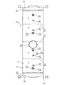
- FIG. 1 It is a left side view which shows the ISO tank container as an example of the tank container to which the manufacturing method of the tank container which concerns on Embodiment 1 is applied. It is a rear view which shows the ISO tank container as an example of the tank container which applied the manufacturing method of the tank container which concerns on Embodiment 1.
- FIG. It is a top view which shows the tank of the tank container to which the manufacturing method of the tank container which concerns on Embodiment 1 was applied. It is a bottom view which shows the tank of the tank container to which the manufacturing method of the tank container which concerns on Embodiment 1 was applied.
- FIG. 1 It is a perspective block diagram which shows the main part of the tank of the tank container to which the manufacturing method of the tank container which concerns on Embodiment 1 is applied. It is a perspective block diagram which shows the inside of the tank of the tank container to which the manufacturing method of the tank container which concerns on Embodiment 1 is applied. It is sectional drawing which shows the injection port of the tank of the tank container to which the manufacturing method of the tank container which concerns on Embodiment 1 was applied. It is sectional drawing which shows the attachment structure of the supply pipe of the tank of the tank container to which the manufacturing method of the tank container which concerns on Embodiment 1 was applied.
- FIG. 1 It is sectional drawing which shows the covering part of the end plate of the tank of the tank container to which the manufacturing method of the tank container which concerns on Embodiment 1 was applied. It is a top view which shows the spill box part of the tank container to which the manufacturing method of the tank container which concerns on Embodiment 1 was applied. It is a side view which shows the spill box part of the tank container to which the manufacturing method of the tank container which concerns on Embodiment 1 was applied. It is a top view which shows the container frame of the tank container to which the manufacturing method of the tank container which concerns on Embodiment 1 was applied. It is a side view which shows the container frame of the tank container to which the manufacturing method of the tank container which concerns on Embodiment 1 was applied.
- FIG. 1 (a) is a left side view showing an ISO tank container as an example of a tank container to which the method for manufacturing a tank container according to the first embodiment of the present invention is applied, and FIG. 1 (b) shows an ISO tank container. It is a rear view.
- the ISO tank container 1 is roughly classified into a tank 2 as an example of a pressure-resistant container for accommodating a dangerous substance powder P as an example of powder, and a container frame portion for fixing the tank 2. It is composed of a container frame 3 as an example.
- the tank 2 has a tank body 4 formed in an airtight cylindrical shape in which dangerous substance powder P is housed and both ends are closed along the longitudinal direction, and a lower portion of the tank body 4 in the longitudinal direction.
- the upper end portion as an example of the base end portion is airtightly joined to the inner wall of the tank body 4 and the adjacent portions, and the lower end portion as an example of the tip end portion of the tank body 4 is arranged so as to be adjacent to each other.
- the hazardous substance powder P include lithium hexafluorophosphate, lithium tetrafluoroborate, lithium bis (fluorosulfonyl) imide, lithium difluorophosphate, and high-purity lithium hydroxide.
- the powder is not limited to the above powder.
- the tank main body 4 is formed in an airtight cylindrical shape in which both ends are closed along the longitudinal direction.
- the tank body 4 includes a cylindrical portion 7 formed in a cylindrical shape, and end plates 8 and 9 formed in a dish shape or a semi-elliptical shape that airtightly close both ends of the cylindrical portion 7 along the longitudinal direction, respectively.
- the cylindrical portion 7 of the tank main body portion 4 is formed by joining, for example, a stainless steel plate having a thickness of about 4.4 mm to a cylindrical shape by welding or the like.
- the end plates 8 and 9 are formed by, for example, bending a stainless steel plate having a thickness of about 5.3 mm, which is thicker than the cylindrical portion 7, into a dish shape or a semi-elliptical shape.
- the end plates 8 and 9 are airtight because a plurality of accommodating portions and discharging portions 5 are installed at predetermined positions in the tank main body 4 and then joined to both ends of the cylindrical portion 7 along the longitudinal direction by welding or the like.
- a tank body 4 formed in a cylindrical shape is formed.
- the tank main body 4 is fixed to the container frame 3 via collar members 10 and 11 as an example of short cylindrical mounting members joined to both ends of the end plates 8 and 9 along the longitudinal direction by welding or the like. It is attached with.
- the inner peripheral surface of the tank main body 4 has notches in an annular shape or a part thereof arranged at equal intervals between four accommodating parts and discharging parts 5 adjacent to each other along the longitudinal direction of the tank main body 4. It is reinforced by annular reinforcing members 12 and 13.
- the tank body 4 is divided into four regions along the longitudinal direction corresponding to the four accommodating and discharging portions 5.
- the reinforcing members 12 and 13 are arranged at the boundary of each accommodating portion and discharging portion 5 in the tank main body portion 4.
- a plate material made of a stainless steel plate or the like formed in a U-shaped cross section is used in order to provide light weight and sufficient strength.
- the reinforcing members 12 and 13 are fixed to the inner peripheral surface of the tank main body 4 by joining (welding) the tips of the opposing side plates along the inner peripheral surface of the tank main body 4.
- the reinforcing member 13 arranged at the center of the tank main body 4 along the longitudinal direction is formed in an annular shape having a notch 14 in part, and the notch is formed. 14 is arranged so as to be located at the upper end of the tank main body 4.
- the annular reinforcing member 13 having a notch 14 in part is closed by a plate member 15 having the same cross-sectional shape as the reinforcing member 13 at both ends along the circumferential direction. Has been done.
- the length of the tank body 4 is set to a value corresponding to the length of the ISO container.
- the container frame 3 is configured to have a length, width, and height corresponding to these numerical values.
- the tank main body 4 fixed to the container frame 3 is formed to have a length slightly shorter than that of the container frame 3.
- the outer diameter of the tank main body 4 takes into consideration the height of members such as on-off valves 24 and 62 attached to the upper end and the lower end of the tank main body 4. , The value (small diameter) smaller than the height and width of the container frame 3 is set.
- a manhole 16 is provided on the upper end surface of the tank main body 4 slightly behind the center along the longitudinal direction thereof.
- the manhole 16 is formed in a cylindrical shape having a required opening diameter and height so as to project upward from the upper end surface of the tank main body 4.
- a charging port 22 for charging the dangerous substance powder P, which is contained in the tank main body 4 is provided in the longitudinal direction.
- a plurality of (four in the illustrated example) openings are provided along the line.
- the input port 22 is opened at a position (directly above) corresponding to the discharge port 61 of the four accommodating portions and discharge portions 5 shown in FIG. 6 or at a position corresponding to the vicinity of the discharge port 61 (position directly above the discharge port).
- a disk-shaped input port forming plate 23 made of stainless steel or the like having a required thickness is joined by welding or the like at a position corresponding to the input port 22 of the tank body 4. Has been done.
- the input port forming plate 23 is opened with an input port 22 having a cylindrical upper end and a conical diameter at the lower end.
- a 2-inch ball valve 24 (see FIG. 1) is attached to the inlet forming plate 23 as an example of an on-off valve for opening and closing the inlet 22 by bolting or the like (not shown) facing upward.
- the ball valve 24 can be made shorter (lower) in length along the axial direction including the opening / closing mechanism, and can be made smaller (lower surface). There is. Therefore, by adopting a ball valve 24 having a relatively small diameter as an on-off valve provided on the upper end surface of the tank main body 4, the height of the tank main body 4 can be kept low.
- one or more introduction ports 25 for introducing pressurized gas into the tank main body 4 are provided along the longitudinal direction.
- the pressurized gas for example, dry (water-removed) nitrogen gas N 2 is used.
- the four inlets 25 are provided corresponding to the four accommodating portions and discharging portions 5, respectively.
- a supply pipe 29 for supplying pressurized gas via a second on-off valve 28 arranged along the horizontal direction is provided on one side surface of the tank body 4 ( In the illustrated example, it is connected toward the right side).
- Each supply pipe 29 is connected to a supply pipe 30 arranged horizontally so as to face forward along the right side surface of the tank main body 4 as viewed in a plane.
- the tip 30a of the supply pipe 30 is arranged so as to straddle the upper end surface of the front end of the tank body 4 toward the opposite side surface (left side), and is arranged so as to straddle the outer peripheral surface (left side) of the tank body 4. It is arranged so as to extend downward along the surface).
- a first supply valve 31 for supplying high-pressure nitrogen gas as an example of the pressurized gas is provided at the tip (lower end) of the supply pipe 30.
- a pressure gauge 32 for detecting the pressure of high-pressure nitrogen gas is attached to the tip (lower end) 30a of the supply pipe 30.
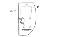
- the on-off valve 28 connected to each introduction port 25 provided on the upper end surface of the tank main body 4 is opened / closed driven by an actuator 34 operated by compressed air, as shown in FIGS. 4 (b) and 5. ..
- each actuator 34 four pipes 35 for supplying nitrogen gas as an example of compressed air are arranged along the supply pipe 30. The tips of the four pipes 35 are connected to the large diameter portion 76a of the supply pipe 76, which will be described later, via the control box 36.
- a switching valve (not shown) for individually switching the supply of nitrogen gas to the four pipes 35 is provided inside the control box 36. Therefore, by operating the control box 36, the operator can individually switch and supply the nitrogen gas pressurized from each introduction port 25 to the four accommodating portions and discharging portions 5 of the tank main body portion 4. It has become.
- a safety valve 37 is attached to the upper end surface of the tank body 4 on the left side surface on the rear side of the manhole 16 along the longitudinal direction of the tank body 4.
- the safety valve 37 opens when the pressure in the tank main body 4 reaches a predetermined set pressure, and releases (communicates) the pressure in the tank main body 4 to the atmosphere.
- the mounting position of the safety valve 37 is not particularly limited as long as it is the upper end surface of the tank body 4.
- the lower ends of the four accommodating and discharging portions 5 formed in a downward cone shape are attached to the tank main body 4.
- a plurality (4) openings 39 having an elliptical shape are provided so as to project downward from the lower surface.
- the four openings 39 are arranged along the longitudinal direction of the tank main body 4 at intervals equal to the arrangement intervals of the four accommodating portions and discharging portions 5.
- FIG. 1A four accommodating portions and discharging portions 5 are arranged adjacent to each other in the longitudinal direction in the lower portion of the tank main body portion 4.
- the four accommodating portion and discharging unit 5 the first housing portion and the discharge portion 5 1 from the front side of the tank body 4 in this order, the second housing section and the discharge section 5, second 3 of the housing portion and the discharge portion 5, third and fourth housing part and the discharge part 5 4.
- the second and third accommodating portions / discharging portions 5 2 , 5 3 arranged in the central portion along the longitudinal direction of the tank main body portion 4 and the tank main body the first and fourth two housing portions and the discharge portion 5 1, 5 4 each other disposed at both ends in the longitudinal direction of the parts 4 are respectively formed in the same shape.
- the first and fourth two accommodating portions and discharging portions 5 1 , 5 4 arranged at both ends along the longitudinal direction of the tank main body 4 have members arranged on one side thereof. housing portion and a discharge portion 5 2, 5 3, but members disposed other side is a mirror plate 8, 9 of the tank body 4. Therefore, the first and fourth two housing portions and the discharge portion 5 1, 5 4 are different second and third two housing portions and the discharge portion 5 2, 5 3 and shape.
- first to fourth respective housing portion and the discharge portion 51 to 5 4 are in common that essentially all formed in a downward conical shape.
- Each housing part and discharge part 5 1-5 4 for example, constituted by thickness is processed plate material such as stainless steel plate of about 5.3mm in a curved shape.
- the first embodiment as shown in FIG. 6, has a conical shape downward (reversed) to the housing portion and the discharge portion 51 to 5 4 has a downwardly along the vertex in a vertical direction .
- the vertex angle of each of the accommodating parts and discharge part 5 1-5 4 are each set to 90 degrees.
- each of the accommodating parts and discharge part 5 1-5 4 the angle of repose of dangerous goods powder P defined by the inclination angle of the side surface 50 of conical shape has become 45 degrees.
- the angle of the apex of each accommodating portion / discharging portion 5 is not limited to 90 degrees, and may be set to an angle smaller than 90 degrees (for example, about 80 degrees).
- the housing part and discharge part 5 1-5 4 was formed in a conical shape, the housing part and discharge part 5 1-5 4 is not limited to the conical shape, the four It may be formed into a polygonal pyramid shape such as a pyramid, a pentagonal pyramid, a hexagonal pyramid, or an octagonal pyramid.
- both ends of the first to fourth accommodating portions and discharging portions 5 1 to 54 along the longitudinal direction of the tank main body portion 4 are accommodating portions. are respectively cut at and discharge section 5 1-5 4 of the upper end surface and the tank longitudinal direction and intersecting the main body 4 (perpendicular) to the plane, it is formed to have a curved edge 51 and 52 of the side generally U-shaped ing.
- the first to fourth accommodating portions and discharging portions 5 1 to 54 are both ends along a direction intersecting the longitudinal direction of the tank main body portion 4.
- the surfaces are cut along the outer peripheral surface of the cylindrical portion 7 of the tank main body portion 4, and are formed into a shape having curved end edges 53 and 54 having a substantially U-shaped side surface.
- housing portion and the discharge portion of the first and fourth 5 1, 5 4 both end faces of the outer along its longitudinal direction, is cut respectively along the inner surface shape of the tank body 4 of the end plate 8, 9 , As shown in FIG. 1 (a), are formed on the side edges 55 and 56 having a substantially U-shaped side surface.
- the width W of each of the first to fourth accommodating portions and discharging portions 5 1 to 54 along the direction intersecting the longitudinal direction of the tank main body 4 is the tank main body.
- the value is set to be equal to the inner diameter of the cylindrical portion 7 of the portion 4.
- the length L along the longitudinal direction of the tank main body 4 divides the total length of the cylindrical portion 7 of the tank main body 4 into four equal parts. It is set to the desired length.
- the tank container 1 according to the first embodiment, the time of manufacture of the tank container 1, as shown in FIG. 6, the first to the housing portion and the discharge portion of the fourth formed conically 5 1 1-5 4 is not directly use the first to the respective housing portion and the discharge portion 5 of the fourth, as shown in FIG. 7, the upper end surface and the tank body 4 of the conical shape formed in a conical shape
- Two semi-conical constituent members 57 and 58 divided into two by a plane along the direction intersecting (orthogonal) with the longitudinal direction of the tank body 4 are joined to each other when they are installed inside the tank body 4. It is formed in a shape.
- the two constituent members 57 and 58 constituting the first to fourth accommodating portions and discharging portions 5 1 to 54 are the first and fourth accommodating and discharging portions 5 1, and 5 4, are different from the shape of the second and third two housing portions and the discharge portion 5 2, 5 3 in its edge.
- the first step of forming the cylindrical portion 7 of the tank main body 4 formed into a cylindrical shape and the lower portion of the tank main body 4 are arranged so as to be adjacent to each other in the longitudinal direction.
- the upper end is airtightly joined to the inner wall of the tank body 4 and the adjacent parts, and the lower end is formed in a downward conical shape so as to protrude downward from the opening 39 of the tank body 4.
- the second step of forming the semi-conical constituent members 57, 58 divided into two by the plane intersecting the longitudinal direction in the tank main body 4, and the two constituent members 57, 58 are divided into the tank main body 4 was carried into the, a third step of forming a respective housing part and discharge part 5 1-5 4 by bonding the respective constituent members 57 and 58 divided into two in the interior of the tank body 4, Is configured to include.
- FIG. 7 (a) two housing portions and the discharge portion 51 to 5 4 disposed inside the tank body portion 4, as shown in FIG. 6, has a width substantially equal to W and the inner diameter of the tank body 4 ing. Therefore, receiving unit and the discharge unit 5 1-5 4, it is difficult to carry on the inside of the tank body portion 4 after forming a conical shape. Therefore, in the first embodiment, as shown in FIG. 7 (a), 2 single advance a plane passing through the orthogonal and the center on the upper end face of the respective housing part and discharge part 5 1-5 4 conical The semi-conical constituent members 57 and 58 are formed. Then, after carrying the semi-conical constituent members 57 and 58 divided into two into the inside of the cylindrical portion 7 of the tank main body 4, as shown in FIGS.
- constituent members 57 and 58 are joined (welded) to each other.
- constituent members 57 and 58 formed in a semi-conical shape, the elastic deformation less rigid differs from the accommodating portion and discharging unit 5 1-5 4 formed in a conical shape are possible, the tank body 4 It is possible to easily carry it in and join it at a desired position.
- a strip-shaped plate material is previously attached to the joint end of one of the constituent members 57 and 58. It is desirable to join 59. By doing so, when the two constituent members 57 and 58 are joined to each other, the joint ends of one constituent member 57 and the joint ends of the other constituent member 58 are joined by welding or the like in a state of being accurately joined to each other. Is possible.
- the strip-shaped plate member 59 may be configured to be along the outer surface of the joint end when the two constituent members 57 and 58 are joined.
- the strip-shaped plate material 59 has an opening of the tank main body 4 as shown in FIG.
- the third accommodating portion is used. and performed discharge section 5 3 first, second housing section and the discharge section 5 2 is bonded to subsequent adjacent, further, the fourth housing part and the discharge part 5 4 are joined, the end first housing parts and discharge part 5 1 is joined.
- part 5 3 carries the two components 57 and 58 constituting the end portion of the cylindrical portion 7 being opened, these two components 57 and 58 by joining the third housing portion and the discharge portion 5 3 To form.
- the third housing portion and the discharge portion 5 3 of the cylindrical portion 7 of the upper end the tank body 4 facing the inner surface of the cylindrical portion 7 of the tank body 4 of the upper end portion integrally formed It is joined (welded) to the inner surface of.
- the third accommodating portion also serves as a third accommodating portion so as to have an appropriate positional relationship with the reinforcing members 12 and 13.
- the discharge part 5 3 is joined.
- the cylindrical portion 7 of the tank main body 4 is joined to the reinforcing members 12 and 13 on the inner surface thereof, and then the lower portion of the inner peripheral surface of the reinforcing members 12 and 13 is joined.
- a substantially crescent-shaped partition plate 60 is joined (welded) to (lower half) so as to intersect (orthogonally) the longitudinal direction along the inner peripheral surfaces of the reinforcing members 12 and 13.
- the second housing portion and the upper end of the discharge portion 5 2 as shown in FIG. 9, the third housing portion and the discharge portion 5 3 of the upper and airtight manner bonded via the partition plate 60 Will be done.
- the second housing portion and the discharge portion 5 2 joined in an airtight manner on the inner surface of the upper edge 53, 54 cylindrical portion 7 along a direction intersecting the longitudinal direction of the tank body 4 of the upper edge ( Will be welded).
- the first and fourth accommodating portions and discharging portions 5 1 , 5 4 are joined to the cylindrical portion 7 of the tank main body portion 4, respectively.
- the lower portion of the tank main body 4 is arranged so as to be adjacent to each other along the longitudinal direction thereof, the upper end portion is airtightly joined to the inner wall of the tank main body 4 and the adjacent portions, and the lower end portion is formed.
- Four accommodating portions and discharging portions 5 1 to 54 formed in a downward conical shape so as to project downward from the opening 3 of the tank main body portion 4 are provided. It should be noted that the space between the outer peripheral surface of the lower portion of the tank body 4 (cylindrical portion 7) and the inner peripheral surface of the first to fourth accommodating portions and discharging portions 5 1 to 54 is shown in FIG. 4 (c). As described above, a gap G composed of an air layer is formed.
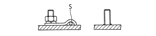
- an exhaust pipe 59 is provided on the outer peripheral surface of the tank body 4 (cylindrical portion 7) to discharge air from the gap G to the outside due to a change in external temperature or the like. Further, on the outer peripheral surface of the tank body 4 (cylindrical portion 7), as shown in FIGS. 1A and 4D, a temperature detection sensor S for detecting the temperature of the cylindrical portion 7 of the tank body 4 is provided. Arranged to make contact.
- each ball valve 62 is extended so that its operating portion 62a is located on the left side surface of the tank main body portion 4 via the universal joint 62b and the operating shaft 62c.
- a discharge pipe 65 for transporting the dangerous substance powder P discharged from the ball valve 62 is along the longitudinal direction of the tank body 4. It is installed almost horizontally.
- An introduction pipe 67 for introducing pressurized gas via a check valve 66 is connected to an end portion of the discharge pipe 65 on the front side along the longitudinal direction of the tank body 4.
- a second supply valve 68 for supplying high-pressure nitrogen gas as an example of the pressurized gas is connected to the tip of the introduction pipe 67.
- each injection port 70 is opened in the injection port forming plate 71.
- Each injection port forming plate 71 as shown in FIG. 10 (a), from the injection port 70 is inserted into the respective accommodating portions and the discharge portion 51 to 5 4, a cylindrical injecting the pressurized gas
- the filter member 72 is attached with the filter member 72 inserted.
- the filter member 72 is airtightly attached to the tip of a second supply pipe 73 that supplies high-pressure nitrogen gas.
- the tip of the second supply pipe 73 is fixed to the connecting member 75a attached to the injection port forming plate 71 via the packing 74.
- the second supply pipe 73 is connected to the supply pipe 76 arranged horizontally so as to face forward along the left side surface of the tank main body 4 as viewed in a plane.
- An on-off valve 75 is provided between the second supply pipe 73 and the supply pipe 76, respectively.
- Supply pipe 76 as shown in FIG. 10 (b), between the third housing portion and the discharge portion 5 3 of the fourth housing part and the discharge part 5 4, toward the inside the container frame 3 It is supported by a support member 78 attached in an inclined state.
- a large diameter portion 76a whose diameter has been expanded on the front side of the tank main body 4 is provided.
- the large-diameter portion 76a of the supply pipe 76 has a tip portion that is further bent downward, and a third supply valve 79 at the tip that is bent downward. Are connected horizontally.
- the rear side of the second supply valve 68 is bent upward and is connected to the large diameter portion 76a of the supply pipe 76. Therefore, the high-pressure nitrogen gas supplied from the third supply valve 79 is supplied to the large-diameter portion 76a of the supply pipe 76, and then to the second supply valve 68 via the large-diameter portion 76a of the supply pipe 76. It is supplied and supplied to the discharge pipe 65 via the second supply valve 68, the introduction pipe 67, and the check valve 66.
- the outer peripheral surface of the tank main body 4 is covered with the heat insulating material 80 (see FIG. 11) constituting the heat insulating portion 6.
- the heat insulating material various materials such as urethane foam, polystyrene foam, polyethylene foam, glass foam, and rock foam can be used depending on the material, but it is desirable to use urethane foam in terms of heat insulating properties.
- urethane foam having a thickness of 100 mm is used.
- the surfaces of the end plates 8 and 9 of the tank main body 4 are made of glass wool 81 having a thickness of 25 mm in consideration of strength, and the surface of the glass wool 81 is made of aluminum. It is covered with a film 82 made of.
- spill box portions 91 to 94 that cover openings such as the manhole 16 and the ball valve 24 are provided on the upper end surface of the tank main body portion 4.
- Each of the spill box portions 91 to 94 is configured as a flat rectangular frame whose upper end surface is opened by a metal plate such as stainless steel. Further, on the upper end surfaces of the spill box portions 91 to 94, covers that can be opened and closed are provided. The outer peripheral surfaces of the spill box portions 91 to 94 are covered with the heat insulating material 83.
- drainage pipes 95 to 98 are connected to the spill box portions 91 to 94, respectively. Drainage pipes 95 to 98 are connected to the left and right sides of the tank body 4, respectively. The tips of the drain pipes 95 to 98 are connected to the drain pipe 99, and the tips of the drain pipe 99 are arranged downward on both side surfaces on the rear side of the tank main body 4.
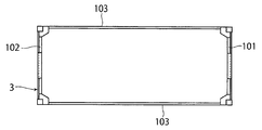
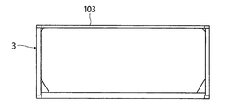
- the container frame 3 for fixing the tank body 4 is formed in a rectangular parallelepiped shape. As described above, the container frame 3 is set to have a length of 6058 mm, a width of 2438 mm, and a height of 2591 mm in the case of a 20-foot container.
- the container frame portion 3 is a beam member that connects the rectangular frame bodies 101 and 102 that form the front end face and the rear side end face, respectively, along the longitudinal direction of the tank container, and the front side and rear side frames. It is equipped with 103.
- the container frame 3 is not limited to the full frame type, and a beam type in which the tip of the frame is coupled to the surface of the tank body may be adopted.
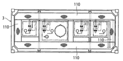
- a walk plate 110 is provided on the upper end surface of the container frame 3 so that an operator can go up to the upper part of the tank container 1 to perform the work.
- the walk plate 110 is arranged between the spill box portions 91 to 94 and the container frame portion 3 on the upper end surface of the container frame 3.
- the dangerous substance powder P can be transported while suppressing contact with moisture in the air and the temperature rise as follows, and the dangerous substance powder can be transported. It is possible to easily discharge P.
- each on-off valve 62 at the bottom of the tank body 4 is closed.
- the material powder P is housed.
- the accommodation rate of Dangerous Goods powder When the P, the four accommodating portion and discharging unit 5 1-5 4 and volume of the inner space of the tank body 4 (approximately 13KL) was 100, set to about 85 to 95% Will be done.
- the supply pipe from the inlet 25 29,30 Nitrogen gas may be introduced into the inside through the tank body 4, and the air remaining inside the tank main body 4 may be replaced with the nitrogen gas.
- pressurized nitrogen gas is supplied to the supply pipes 29 and 30 via the first supply valve 31.
- the tank container 1 is maintained in an airtight state by closing the supply valve 23 and the introduction port 25 after the work of accommodating the dangerous substance powder P is completed. Therefore, the dangerous substance powder P contained in the tank main body 4 does not come into contact with the outside air during storage (including storage) and during transportation. Therefore, even when the hazardous substance powder P is made of lithium hexafluorophosphate or the like, as shown in the following chemical formula, the powder made of lithium hexafluorophosphate or the like contains external moisture. It is rapidly hydrolyzed in contact with hydrogen fluoride, which is extremely toxic and corrosive. LiPF 6 + 4H 2 O ⁇ LiF (lithium fluoride) + 5HF (hydrogen fluoride) + H 3 PO 4 (phosphoric acid)
- the outer circumference of the tank main body 4 is covered with urethane foam as a heat insulating material 80 (see FIG. 11). Therefore, even when the outside air temperature rises, the tank container 1 can be shielded by a heat insulating material (not shown) to prevent heat from being transferred to the inside of the tank body 4, and inside the tank body 4. The temperature rise is suppressed. Therefore, even when lithium hexafluoride phosphate or the like is contained as the dangerous substance powder P, the temperature of the dangerous substance powder P can be maintained at a relatively low temperature, which is the initial environmental temperature, and thermal decomposition can be performed. It is prevented from waking up.
- Tank container 1 hazardous material powder P is accommodated in the four accommodating portion and the inner space of the discharge part 5 1-5 4 and the tank body 4.
- each discharge valve 62 is opened, and an operation of supplying pressurized nitrogen gas as a pressurized gas from the second supply valve 79 is performed.
- the order to open the respective exhaust valve 62 is not particularly limited, for example, the third from the fourth housing part and the discharge part 4 of which is located on the most downstream side of the tank body 4 of the upstream side, the second and the first housing portion and the discharge portion 5 3-5 1 going to open the respective exhaust valve 62 in this order is preferable.
- the dangerous substance powder P can be reliably discharged from the discharge port of the discharge pipe 65 while being assisted by the introduced pressurized gas.
- the dangerous substance powder P to be produced can be reliably discharged from the discharge port of the discharge pipe 65 while being assisted by the introduced pressurized gas.
- the first housing portion and the discharge portion 5 1 of the tank body 4 By finally opens the first discharge valve 62 of the first housing portion and the discharge portion 5 1 of the tank body 4, the first housing portion and the discharge portion 5 1 of the first discharge valve 62
- the dangerous substance powder P discharged from the discharge pipe 65 can be reliably discharged from the discharge port of the discharge pipe 65 while being assisted by the introduced pressurized gas.
- the present invention is not limited to this, and the discharge valves 62 of the first to fourth accommodating parts and discharge parts 5 1 to 54 are opened at the same time to discharge the dangerous substance powder P to the discharge port of the discharge pipe 65. Of course, it may be discharged from.
- the tank connector 1 Since the tank connector 1 has a structure having the above-mentioned operation mechanism, it can have high airtightness.
- the leak rate of the gas inside the tank container 1, which is a measure of airtightness, is the time when a gas (inert gas such as air, nitrogen, helium, etc.) of a constant pressure is sealed inside the tank container 1 and a certain period of time elapses. It can be confirmed from the pressure change and temperature change.
- the leak rate of the tank connector 1 according to the present embodiment was determined to be 5.2 ⁇ 10 -5 Pa ⁇ m 3 / sec, which is a standard of airtightness 1.0 ⁇ 10 -4 Pa ⁇ m 3 /. Since it is sec or less, the dangerous substance powder P can be transported while being suppressed from coming into contact with the moisture in the air, and the dangerous substance powder P can be easily discharged. As a result, mass transportation of high value-added dangerous substance powder (effective volume 11.3 KL) becomes possible.
Landscapes
- Engineering & Computer Science (AREA)
- Mechanical Engineering (AREA)
- Architecture (AREA)
- Civil Engineering (AREA)
- Structural Engineering (AREA)
- Filling Or Discharging Of Gas Storage Vessels (AREA)
- Filling Or Emptying Of Bunkers, Hoppers, And Tanks (AREA)
Abstract
危険物粉体等からなる粉体が空気中の水分と接触したり予め定められた温度以上に温度が上昇するのを抑制しつつ収容及び輸送が可能であり、粉体の排出も容易に行うことが可能なタンクコンテナ及びその製造方法を提供する。 内部に粉体が収容され、長手方向に沿った両端が閉塞された気密な円筒形状に形成されたタンク本体部と、前記タンク本体部内の下部に長手方向に沿って互いに隣接するよう配置され、基端部が前記タンク本体の内壁及び隣接部同士と気密に接合されるとともに、先端部が前記タンク本体部の外周面に設けられた開口から外部へ向けて突出するよう逆向きの錐形状に形成された複数の収容部兼排出部と、前記タンク本体部の外周面に設けられた断熱部と、前記タンク本体部が固定されたコンテナフレーム部と、を備える。
Description
この発明は、タンクコンテナ及びその製造方法に関する。
従来、タンクコンテナは、液体や粉体、あるいは高圧ガス等の気体などを搬送する際に幅広く使用されている。特に、ISOタンクコンテナは、ISOで定められた規格に合致したコンテナであるため、トレーラーやコンテナ船などによる国内はもとより海外への輸送に適している。
タンクコンテナによって搬送される内容物は、上述した液体や粉体、あるいは気体などの形態による区分以外に、化学品・危険物・医薬品原料から食料品類に至るまで多岐にわたる。その中でも六フッ化リン酸リチウムは、リチウム/リチウムイオン二次電池の電解液の原料であり、国内は勿論のこと海外に輸出するニーズが高まってきている。
六フッ化リン酸リチウムは、白色の結晶性粉末であり、空気中の水分と接触すると、下記の化学式に示されるように、急速に加水分解して極めて毒性や腐蝕性が高いフッ化水素を生成する。
LiPF6+4H2O
→LiF(フッ化リチウム)+5HF(フッ化水素)+H3PO4(リン酸)
また、六フッ化リン酸リチウムは、空気中の水分と接触すると、酸が発生することにより収容容器の金属が腐蝕してコナミネーションが発生し、品質が低下するリスクを有している。
LiPF6+4H2O
→LiF(フッ化リチウム)+5HF(フッ化水素)+H3PO4(リン酸)
また、六フッ化リン酸リチウムは、空気中の水分と接触すると、酸が発生することにより収容容器の金属が腐蝕してコナミネーションが発生し、品質が低下するリスクを有している。
また、六フッ化リン酸リチウムは、熱的安定性が低く、60℃程度の比較的低い温度で熱分解を起こす。
そのため、六フッ化リン酸リチウム(粉体)を収容して運搬するには、空気中の水分と接触させない気密性と、一定温度以下に維持する温度安定性が要求される。また、六フッ化リン酸リチウム(粉体)は、品質上、収容や運搬等に際して他の不純物が混入される虞れがなく、高純度の状態を維持した搬送が求められる。
一般に、粉体用の輸送容器としては、次のようなダンプ方式、加圧方式、ブロー方式を採用したものがある。
1) ダンプ方式
ダンプ方式は、角型容器のような輸送容器に粉体を収容し、輸送容器の排出口と反対側の端部を持ち上げて、輸送容器を傾斜させることにより重力で粉体を排出する方式である。このダンプ方式は、角型容器のように粉体を収容する輸送容器を大容量化することができる利点を有している。また、粉体の安息角以上に輸送容器を傾斜させれば粉体を排出することができ、安定した排出が可能である。その反面、ダンプ方式は、輸送容器の排出口が大気に晒されるため、気密性を保持し難い。
1) ダンプ方式
ダンプ方式は、角型容器のような輸送容器に粉体を収容し、輸送容器の排出口と反対側の端部を持ち上げて、輸送容器を傾斜させることにより重力で粉体を排出する方式である。このダンプ方式は、角型容器のように粉体を収容する輸送容器を大容量化することができる利点を有している。また、粉体の安息角以上に輸送容器を傾斜させれば粉体を排出することができ、安定した排出が可能である。その反面、ダンプ方式は、輸送容器の排出口が大気に晒されるため、気密性を保持し難い。
2) 加圧方式(耐圧容器)
加圧方式は、粉体を収容した容器自体を傾斜させず耐圧容器内に気体を導入し、粉体を舞い上げて密度を低くした状態で粉体の排出を行う方式である。この加圧方式は、一度の加圧及び排出ではなく、この加圧及び排出を複数回繰り返して排出する場合が多い。加圧方式は、真密度の低い粉体で使用される場合が多く、六フッ化リン酸リチウム(粉体)のように密度が高い粉体には適用することが困難である。
加圧方式は、粉体を収容した容器自体を傾斜させず耐圧容器内に気体を導入し、粉体を舞い上げて密度を低くした状態で粉体の排出を行う方式である。この加圧方式は、一度の加圧及び排出ではなく、この加圧及び排出を複数回繰り返して排出する場合が多い。加圧方式は、真密度の低い粉体で使用される場合が多く、六フッ化リン酸リチウム(粉体)のように密度が高い粉体には適用することが困難である。
3) ブロー方式
ブロー方式は、加圧方式よりも更に粉体を舞い上げて密度を低くするため、横型容器の長手方向に沿った底部に気体を通す矩形状の流路を設け、その流路の上面を気体の通過を許容する布(キャンバス地)張り状態とし、この布を通して容器内の粉体を舞い上げて排出する方式である。ブロー方式の排出口は、1つに限らず、複数個有する場合もあり、閉塞しないよう上向きの配管となっている。ブロー方式は、キャンバス地が合成繊維等の有機材料からなり、またキャンバス地を固定するのに使用する部品が脱着するなど不純物が混入するリスクがある。ブロー方式は、機密性に乏しく、粉体の排出残量が多い。
ブロー方式は、加圧方式よりも更に粉体を舞い上げて密度を低くするため、横型容器の長手方向に沿った底部に気体を通す矩形状の流路を設け、その流路の上面を気体の通過を許容する布(キャンバス地)張り状態とし、この布を通して容器内の粉体を舞い上げて排出する方式である。ブロー方式の排出口は、1つに限らず、複数個有する場合もあり、閉塞しないよう上向きの配管となっている。ブロー方式は、キャンバス地が合成繊維等の有機材料からなり、またキャンバス地を固定するのに使用する部品が脱着するなど不純物が混入するリスクがある。ブロー方式は、機密性に乏しく、粉体の排出残量が多い。
更に、粉体の輸送が可能なタンクコンテナに関する技術としては、例えば、特許文献1等に開示されたものが既に提案されている。
特許文献1は、ばら粉体の輸送用の細長容器であって、前記容器の底は、前記容器の長さの少なくとも一部に沿って延在する長手方向に傾斜する薄膜支持体を備え、気体透過性薄膜は前記支持体に取り付けられ、前記支持体は、その長手方向端間及び横方向端間において、前記容器に対して支持されていないよう構成したものである。
この発明の目的は、危険物粉体等からなる粉体が空気中の水分と接触したり予め定められた温度以上に温度が上昇するのを抑制しつつ収容及び輸送が可能であり、粉体の排出も容易に行うことが可能なタンクコンテナ及びその製造方法を提供することにある。
請求項1に記載された発明は、内部に粉体が収容され、長手方向に沿った両端が閉塞された気密な円筒形状に形成されるタンク本体部と、
前記タンク本体部内の下部に長手方向に沿って互いに隣接するよう配置され、上端部が前記タンク本体の内壁及び隣接部同士と気密に接合されるとともに、下端部が前記タンク本体部の外周面に設けられた複数の開口から外部へ向けてそれぞれ突出するよう下向きの錐形状に形成される複数の収容部兼排出部と、
前記タンク本体部の外周面に設けられる断熱部と、
前記タンク本体部が固定されるコンテナフレーム部と、
を備えるタンクコンテナである。
前記タンク本体部内の下部に長手方向に沿って互いに隣接するよう配置され、上端部が前記タンク本体の内壁及び隣接部同士と気密に接合されるとともに、下端部が前記タンク本体部の外周面に設けられた複数の開口から外部へ向けてそれぞれ突出するよう下向きの錐形状に形成される複数の収容部兼排出部と、
前記タンク本体部の外周面に設けられる断熱部と、
前記タンク本体部が固定されるコンテナフレーム部と、
を備えるタンクコンテナである。
請求項2に記載された発明は、前記タンク本体部の内周面は、前記タンク本体部の長手方向に沿って互いに隣接する前記複数の収容部兼排出部の間に配置された環状又は一部に切欠きを有する環状の補強部材により補強されている請求項1に記載のタンクコンテナである。
請求項3に記載された発明は、前記複数の収容部兼排出部は、その傾斜角が前記粉体の安息角以上に設定されている請求項1に記載のタンクコンテナである。
請求項4に記載された発明は、前記タンク本体部の上端部には、前記タンク本体部内に加圧気体を導入する導入口が長手方向に沿って1つ以上設けられている請求項1に記載のタンクコンテナである。
請求項5に記載された発明は、前記タンク本体部の上端部には、前記複数の収容部兼排出部に前記粉体を供給する供給口が前記複数の収容部兼排出部に対応してそれぞれ設けられている請求項1に記載のタンクコンテナである。
請求項6に記載された発明は、前記複数の収容部兼排出部の下端部には、前記複数の収容部兼排出部に収容された前記粉体に対して加圧気体を噴射する噴射口がそれぞれ設けられている請求項1に記載のタンクコンテナである。
請求項7に記載された発明は、前記複数の収容部兼排出部は、下向きの円錐形状に形成され、下端部に前記粉体を排出する排出口が開口されているとともに、前記排出口は、ボールバルブからなる排出弁により開閉される請求項1に記載のタンクコンテナである。
請求項8に記載された発明は、前記複数の収容部兼排出部は、前記タンク本体部の長手方向と交差する方向に沿った平面で半円錐形状に分割された2つの各構成部材を、前記タンク本体部の内部で互いに接合することにより円錐形状に形成される請求項7に記載のタンクコンテナである。
請求項9に記載された発明は、前記タンク本体部には、その長手方向に沿った両端部に環状に形成された取付部材がそれぞれ固定され、
前記タンク本体部は、前記取付部材を介して前記コンテナフレーム部に固定されている請求項1に記載のタンクコンテナである。
前記タンク本体部は、前記取付部材を介して前記コンテナフレーム部に固定されている請求項1に記載のタンクコンテナである。
請求項10に記載された発明は、前記タンク本体部の上端部には、当該タンク本体部の上端部に設けられた開口部の外周を囲むよう平面矩形の枠体状に形成されたスピルボックス部が設けられ、前記スピルボックス部の外側面は、断熱材によって被覆されている請求項1に記載のタンクコンテナである。
請求項11に記載された発明は、少なくとも一方の端部が開口された円筒形状のタンク本体部を形成する第1の工程と、
前記タンク本体部内の下部に長手方向に沿って互いに隣接するよう配置され、上端部が前記タンク本体の内壁及び隣接部同士と気密に接合されるとともに、下端部が前記タンク本体部の外周面に設けられた開口から外部へ向けて突出するよう下向きの円錐形状に形成される複数の収容部兼排出部であって、前記複数の収容部兼排出部を前記タンク本体部の長手方向と交差する平面で半円錐形状に分割した2つの各構成部材を形成する第2の工程と、
前記2つの各構成部材を前記タンク本体部の内部に搬入し、前記タンク本体部の内部において前記2つの各構成部材を接合して前記複数の収容部兼排出部を形成する第3の工程と、
を備えるタンクコンテナの製造方法である。
前記タンク本体部内の下部に長手方向に沿って互いに隣接するよう配置され、上端部が前記タンク本体の内壁及び隣接部同士と気密に接合されるとともに、下端部が前記タンク本体部の外周面に設けられた開口から外部へ向けて突出するよう下向きの円錐形状に形成される複数の収容部兼排出部であって、前記複数の収容部兼排出部を前記タンク本体部の長手方向と交差する平面で半円錐形状に分割した2つの各構成部材を形成する第2の工程と、
前記2つの各構成部材を前記タンク本体部の内部に搬入し、前記タンク本体部の内部において前記2つの各構成部材を接合して前記複数の収容部兼排出部を形成する第3の工程と、
を備えるタンクコンテナの製造方法である。
この発明によれば、危険物粉体等からなる粉体が空気中の水分と接触したり予め定められた温度以上に温度が上昇するのを抑制しつつ収容及び輸送が可能であり、粉体の排出も容易に行うことが可能なタンクコンテナ及びその製造方法を提供することができる。
以下に、この発明の実施の形態について図面を参照して説明する。
[実施の形態1]
図1(a)は、この発明の実施の形態1に係るタンクコンテナの製造方法を適用したタンクコンテナの一例としてのISOタンクコンテナを示す左側面図、同図(b)はISOタンクコンテナを示す背面図である。
図1(a)は、この発明の実施の形態1に係るタンクコンテナの製造方法を適用したタンクコンテナの一例としてのISOタンクコンテナを示す左側面図、同図(b)はISOタンクコンテナを示す背面図である。
<タンクコンテナの全体構成>
ISOタンクコンテナ1は、図1に示されるように、大別して、粉体の一例としての危険物粉体Pを収容する耐圧容器の一例としてのタンク2と、タンク2を固定するコンテナフレーム部の一例としてのコンテナフレーム3とから構成されている。タンク2は、内部に危険物粉体Pが収容され、長手方向に沿った両端が閉塞された気密な円筒形状に形成されたタンク本体部4と、タンク本体部4内の下部に長手方向に沿って互いに隣接するよう配置され、基端部の一例としての上端部がタンク本体4の内壁及び隣接部同士と気密に接合されるとともに、先端部の一例としての下端部がタンク本体部4の下面(外周面)に設けられた開口39から下方へ向けて突出するよう下向き(逆向き)の錐形状に形成された複数(図示例では、4つ)の収容部兼排出部5と、タンク本体部4の外周面に設けられた断熱部6と、を備えている。ここで、危険物粉体Pとしては、例えば、六フッ化リン酸リチウムや、四フッ化ホウ酸リチウム、リチウム ビス(フルオロスルホニル)イミド、ジフルオロリン酸リチウム、高純度水酸化リチウム等が挙げられるが、上記粉体に限定されるものではない。
ISOタンクコンテナ1は、図1に示されるように、大別して、粉体の一例としての危険物粉体Pを収容する耐圧容器の一例としてのタンク2と、タンク2を固定するコンテナフレーム部の一例としてのコンテナフレーム3とから構成されている。タンク2は、内部に危険物粉体Pが収容され、長手方向に沿った両端が閉塞された気密な円筒形状に形成されたタンク本体部4と、タンク本体部4内の下部に長手方向に沿って互いに隣接するよう配置され、基端部の一例としての上端部がタンク本体4の内壁及び隣接部同士と気密に接合されるとともに、先端部の一例としての下端部がタンク本体部4の下面(外周面)に設けられた開口39から下方へ向けて突出するよう下向き(逆向き)の錐形状に形成された複数(図示例では、4つ)の収容部兼排出部5と、タンク本体部4の外周面に設けられた断熱部6と、を備えている。ここで、危険物粉体Pとしては、例えば、六フッ化リン酸リチウムや、四フッ化ホウ酸リチウム、リチウム ビス(フルオロスルホニル)イミド、ジフルオロリン酸リチウム、高純度水酸化リチウム等が挙げられるが、上記粉体に限定されるものではない。
タンク本体部4は、図1及び図2に示されるように、長手方向に沿った両端が閉塞された気密な円筒形状に形成されている。タンク本体部4は、円筒形状に形成された円筒部7と、円筒部7の長手方向に沿った両端部をそれぞれ気密に閉塞する皿形状や半楕円形状に形成された鏡板8,9とを有している。タンク本体部4の円筒部7は、例えば、厚さ4.4mm程度のステンレス鋼板等を円筒形状に溶接等により接合することで形成される。鏡板8,9は、例えば、円筒部7より厚い5.3mm程度の厚さのステンレス鋼板等を皿形状や半楕円形状に湾曲させて形成される。鏡板8,9は、タンク本体部4内の予め定められた位置に複数の収容部兼排出部5を設置した後、円筒部7の長手方向に沿った両端部に溶接等により接合され、気密な円筒形状に形成されたタンク本体部4が構成される。
タンク本体部4は、鏡板8,9の長手方向に沿った両端部に溶接等により接合された短い円筒形状の取付部材の一例としてのカラー部材10,11を介してコンテナフレーム3に固定した状態で取り付けられる。
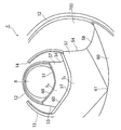
タンク本体部4の内周面は、当該タンク本体部4の長手方向に沿って互いに隣接する4つの収容部兼排出部5の間に等間隔で配置された環状又は一部に切欠きを有する環状の補強部材12,13により補強されている。タンク本体部4は、4つの収容部兼排出部5に対応して長手方向に沿った4つの領域に区分される。補強部材12,13は、タンク本体部4内の各収容部兼排出部5の境界にそれぞれ配置されている。補強部材12,13としては、図3(a)に示されるように、軽量で且つ十分な強度を持たせるため、断面コ字形状に形成されたステンレス鋼板等からなる板材を用いている。補強部材12,13は、その対向する両側板の先端がタンク本体部4の内周面に沿って接合(溶接)されることで、タンク本体部4の内周面に固定されている。タンク本体部4の長手方向に沿った中央部に配置される補強部材13は、図1及び図3(b)に示されるように、一部に切欠き14を有する環状に形成され、切欠き14がタンク本体部4の上端に位置するよう配置される。一部に切欠き14を有する環状の補強部材13は、図3(a)に示されるように、その周方向に沿った両端部が当該補強部材13の断面形状と同一形状の板材15によって閉塞されている。
タンク本体部4の長さは、ISOコンテナの長さに対応した値に設定される。ISOコンテナの一例として、例えば20フィートのタンクコンテナ1の場合は、その長さが6058mm、幅が2438mm、高さが2591mmにそれぞれ設定されている。したがって、コンテナフレーム3は、これらの数値に対応した長さ、幅及び高さに構成されている。コンテナフレーム3に固定されるタンク本体部4は、図1(a)に示されるように、その長さがコンテナフレーム3より若干短く形成されている。また、タンク本体部4の外径は、図1(b)に示されるように、当該タンク本体4の上端部及び下端部に取り付けられる開閉弁24,62等の部材の高さを考慮して、コンテナフレーム3の高さ及び幅より小さな値(小径)に設定されている。
タンク本体部4の上端面には、図2(a)に示されるように、その長手方向に沿った中央よりやや後方にマンホール16が設けられている。マンホール16は、タンク本体部4の上端面から上部へ向けて突出するよう所要の開口径及び高さを有する円筒形状に形成されている。
また、タンク本体部4の上端面には、図2(a)に示されるように、タンク本体部4内に収容する収容物である危険物粉体Pを投入する投入口22が長手方向に沿って複数(図示例では、4つ)開口されている。投入口22は、図6に示される4つの収容部兼排出部5の排出口61と対応した位置(直上)又は排出口61の近傍に対応した位置(直上に隣接した位置)に開口されている。タンク本体部4の投入口22に対応した位置には、図3(c)に示されるように、所要の厚さを有するステンレス等からなる円板状の投入口形成板23が溶接等により接合されている。投入口形成板23には、上端部が円柱形状に形成され、下端部が円錐形状に拡径した投入口22が開口されている。また、投入口形成板23には、投入口22を開閉する開閉弁の一例として2インチのボールバルブ24(図1参照)が上方へ向けて図示しないボルト止め等によりそれぞれ取り付けられている。ボールバルブ24は、他のバタフライ方式のバルブ等に比較して開閉機構を含めてその軸方向に沿った長さを短く(低く)することができ小型化(低面化)が可能となっている。そのため、タンク本体部4の上端面に設けられる開閉弁として相対的に小径のボールバルブ24を採用することにより、タンク本体部4の高さを低く抑えることができる。
さらに、タンク本体部4の上端面には、タンク本体部4の内部に加圧気体を導入する導入口25が長手方向に沿って1つ以上(図示例では、4つ)設けられている。加圧気体としては、例えば、乾燥した(水分が除去された)窒素ガスN2が使用される。4つの導入口25は、4つの収容部兼排出部5にそれぞれ対応して設けられている。各導入口25には、図5に示されるように、水平方向に沿って配置された第2の開閉弁28を介して加圧気体を供給する供給管29がタンク本体部4の一側面(図示例では、右側面)へ向けて接続されている。各供給管29は、タンク本体部4を平面的に見た右側面に沿って前方へ向けて水平方向に配置された供給管30に接続されている。供給管30の先端部30aは、タンク本体部4のフロント側の端部における上端面を反対側の側面(左側面)へ向けて跨いだ状態で配置され、タンク本体部4の外周面(左側面)に沿って下方へと延在するよう配置されている。供給管30の先端(下端)には、図1に示されるように、加圧気体の一例としての高圧窒素ガスを供給する第1の供給弁31が設けられている。なお、供給管30の先端部(下端部)30aには、図4(a)に示されるように、高圧窒素ガスの圧力を検知する圧力計32が装着されている。
タンク本体部4の上端面に設けられた各導入口25に接続された開閉弁28は、図4(b)及び図5に示されるように、圧縮空気で作動するアクチュエータ34によって開閉駆動される。各アクチュエータ34には、圧縮空気の一例としての窒素ガスを供給する4本のパイプ35が供給管30に沿ってそれぞれ配設されている。4本のパイプ35の先端は、制御ボックス36を介して後述する供給管76の大径部76aに接続されている。制御ボックス36の内部には、4本のパイプ35への窒素ガスの供給を個別に切り替える図示しない切替弁が設けられている。そのため、作業者は、制御ボックス36を操作することにより、タンク本体部4の4つの収容部兼排出部5へ各導入口25から加圧された窒素ガスを個別に切り替えて供給することが可能となっている。
また、タンク本体部4の上端面には、図2(a)に示されるように、タンク本体部4の長手方向に沿ったマンホール16よりリア側の左側面に安全弁37が取り付けられている。安全弁37は、タンク本体部4内の圧力が予め定められた設定圧力に達した際に開き、タンク本体部4内の圧力を大気に開放(連通)するものである。安全弁37の取付位置は、タンク本体部4の上端面であれば特に限定されない。
また、タンク本体部4の下端面には、図2(b)に示されるように、下向きの錐形状に形成された4つの収容部兼排出部5の下端部を、当該タンク本体部4の下面から下方へ向けて突出するように挿通する楕円形状の複数(4つ)の開口39がそれぞれ設けられている。4つの開口39は、4つの収容部兼排出部5の配置間隔と等しい間隔を隔ててタンク本体部4の長手方向に沿って配置されている。
収容部兼排出部5は、図1(a)に示されるように、タンク本体部4内の下部において長手方向に沿って互いに隣接した状態で4つ配置されている。ここでは、説明の都合上、4つの収容部兼排出部5を、タンク本体部4のフロント側から順に第1の収容部兼排出部51、第2の収容部兼排出部52、第3の収容部兼排出部53及び第4の収容部兼排出部54とする。4つの収容部兼排出部5のうち、タンク本体部4の長手方向に沿った中央部に配置される第2及び第3の2つの収容部兼排出部52,53同士と、タンク本体部4の長手方向に沿った両端部に配置される第1及び第4の2つの収容部兼排出部51,54同士は、それぞれ同一形状に形成されている。
すなわち、4つの収容部兼排出部5のうち、タンク本体部4の長手方向に沿った中央部に配置される第2及び第3の2つの収容部兼排出部52,53は、その長手方向に沿った両側に配置される部材がいずれも収容部兼排出部51,54である。これに対して、タンク本体部4の長手方向に沿った両端部に配置される第1及び第4の2つの収容部兼排出部51,54は、その一側に配置される部材は収容部兼排出部52,53であるが、その他側に配置される部材はタンク本体部4の鏡板8,9である。そのため、第1及び第4の2つの収容部兼排出部51,54は、第2及び第3の2つの収容部兼排出部52,53と形状が異なっている。
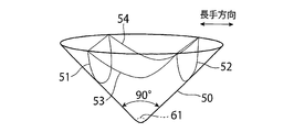
更に説明すると、第1乃至第4の各収容部兼排出部51~54は、基本的に、いずれも下向きの錐形状に形成されている点で共通している。各収容部兼排出部51~54は、例えば、厚さが5.3mm程度のステンレス鋼板等の板材を湾曲形状に加工することにより構成される。この実施の形態1では、図6に示されるように、各収容部兼排出部51~54が頂点を鉛直方向に沿った下方とした下向き(逆向き)の円錐形状に形成されている。各収容部兼排出部51~54の頂点の角度は、それぞれ90度に設定されている。その結果、各収容部兼排出部51~54は、円錐形状の側面50の傾斜角度で規定される危険物粉体Pの安息角が45度となっている。また、各収容部兼排出部5の頂点の角度は、90度に限定されるものではなく、90度より小さな角度(例えば、80度程度)に設定しても良い。この場合、各収容部兼排出部51~54は、側面50の傾斜角度である危険物粉体Pの安息角が45度以上となり、危険物粉体Pをより一層確実に排出することが可能となる。この実施の形態1では、各収容部兼排出部51~54を円錐形状に形成したが、各収容部兼排出部51~54は、円錐形状に限定されるものではなく、四角錐、五角錐、六角錐、八角錐形状など多角錐形状に形成しても良い。
第1乃至第4の各収容部兼排出部51~54は、図6(a)(b)に示されるように、タンク本体部4の長手方向に沿った両端面が、各収容部兼排出部51~54の上端面及びタンク本体部4の長手方向と交差(直交)する平面でそれぞれ切断され、側面略U形の曲線状の端縁51,52を有するように形成されている。
また、第1乃至第4の各収容部兼排出部51~54は、図6(a)(c)に示されるように、タンク本体部4の長手方向と交差する方向に沿った両端面が、タンク本体部4の円筒部7の外周面に沿ってそれぞれ切断され、側面略U形の曲線状の端縁53,54を有する形状に形成されている。
さらに、第1及び第4の収容部兼排出部51,54は、その長手方向に沿った外側の両端面が、タンク本体部4の鏡板8,9の内面形状に沿ってそれぞれ切断され、図1(a)に示されるように、側面略U字形状の端縁55,56に形成されている。
第1乃至第4の各収容部兼排出部51~54は、図6(b)に示されるように、タンク本体部4の長手方向と交差する方向に沿った幅Wが、タンク本体部4の円筒部7の内径と等しい値に設定されている。また、第1乃至第4の各収容部兼排出部51~54は、タンク本体部4の長手方向に沿った長さLが、タンク本体部4の円筒部7の全長を4等分した長さに設定されている。
ところで、この実施の形態1に係るタンクコンテナ1は、当該タンクコンテナ1の製造に際して、図6に示されるように、円錐形状に形成された第1乃至第4の各収容部兼排出部51~54をそのまま使用するのではなく、円錐形状に形成された第1乃至第4の各収容部兼排出部5を、図7に示されるように、円錐形状の上端面及びタンク本体部4の長手方向と交差(直交)する方向に沿った平面で二つに分割した半円錐形状の2つの構成部材57,58を、タンク本体部4の内部に設置する際に互いに接合することで円錐形状に形成している。
なお、第1乃至第4の各収容部兼排出部51~54を構成する2つの構成部材57,58は、上述したように、第1及び第4の2つの収容部兼排出部51,54と、第2及び第3の2つの収容部兼排出部52,53ではその端縁の形状が異なっている。
タンクコンテナ1を製造するに際しては、円筒形状に形成されるタンク本体部4の円筒部7を形成する第1の工程と、タンク本体部4内の下部に長手方向に沿って隣接するよう配置され、上端部がタンク本体4の内壁及び隣接部同士と気密に接合されるとともに、下端部がタンク本体部4の開口39から下方へ向けて突出するよう下向きの円錐形状に形成される4つの収容部兼排出部51~54であって、4つの収容部兼排出部51~54を当該収容部兼排出部51~54の上端面(円錐形状の平面円形状の面)及びタンク本体部4内の長手方向と交差する平面によって2つに分割した半円錐形状の構成部材57,58を形成する第2の工程と、2つの各構成部材57,58をタンク本体部4の内部に搬入し、タンク本体部4の内部において2つに分割された各構成部材57,58を接合することで各収容部兼排出部51~54を形成する第3の工程と、を備えるよう構成されている。
更に説明すると、タンク本体部4の内部に配置される4つの収容部兼排出部51~54は、図6に示されるように、タンク本体部4の内径と略等しい幅Wを有している。そのため、収容部兼排出部51~54は、円錐形状に形成した後にタンク本体部4の内部に搬入することが困難である。そこで、この実施の形態1では、図7(a)に示されるように、各収容部兼排出部51~54を円錐形状の上端面に直交し且つその中心を通る平面で予め2つに分割した半円錐形状の構成部材57,58を形成する。そして、2つに分割した半円錐形状の構成部材57,58をタンク本体部4の円筒部7の内部に搬入した後、図7(b)(c)に示されるように、2つの構成部材57,58を互いに接合(溶接)する。なお、半円錐形状に形成された構成部材57,58は、円錐形状に形成された収容部兼排出部51~54と異なって剛性が低く弾性変形が可能であり、タンク本体部4内の所望の位置に容易に搬入して接合することが可能である。
2つに分割した半円錐形状の構成部材57,58を互いに溶接等により接合するに際しては、図7(d)に示されるように、一方の構成部材57,58の接合端に予め帯状の板材59を接合しておくことが望ましい。こうすることにより、2つの構成部材57,58を互いに接合する際に、一方の構成部材57の接合端と他方の構成部材58の接合端を精度良く付き合わせた状態で溶接等により接合することが可能となる。なお、帯状の板材59は、2つの構成部材57,58を接合する際に接合端の外側面に沿わせるよう構成しても良い。帯状の板材59は、タンク本体部4の開口39と各収容部兼排出部5の間に間隙が生じるのを防止するため、図2(b)に示されるように、タンク本体部4の開口39より上側の領域にのみ設けられる。なお、構成部材57,58の溶接個所の内面は、接合された後に平坦となるよう研磨処理がなされる。
このとき、2つの構成部材57,58を円筒部7の内部に搬入して互いに接合することにより4つの収容部兼排出部51~54を形成する順番は、まず、第3の収容部兼排出部53が最初に行われ、その後隣接する第2の収容部兼排出部52が接合され、更に、第4の収容部兼排出部54が接合され、最後に第1の収容部兼排出部51が接合される。
なお、第3の収容部兼排出部53を最初に接合する理由は、仮に円筒部7のリア側の端部が鏡板8で閉塞されている場合、鏡板8に近い奥側から先に接合作業を実施した方が作業が容易なためである。円筒部7のリア側の端部が鏡板8で閉塞されていない場合は、第3の収容部兼排出部53又は第2の収容部兼排出部52のいずれを先に接合しても良い。
また、円筒部7の鏡板8,9に隣接する第4及び第1の収容部兼排出部54,51を中央部の第3及び第2の収容部兼排出部53,52より後に接合する理由は、第4及び第1の収容部兼排出部54,51は、タンク本体部4の長手方向に沿って形状が前後で同一ではないため、第3及び第2の収容部兼排出部53,52より後に接合することで、先に接合された第3及び第2の収容部兼排出部53,52との位置関係や形状を考慮(調整)して接合作業を行うことができるためである。
まず、タンク本体部4の円筒部7の両端部を鏡板8,9で閉塞する前に、少なくとも一方の端部が開口されたタンク本体部4の円筒部7に、第3の収容部兼排出部53を構成する2つの構成部材57,58を開口されている円筒部7の端部から搬入し、これら2つの構成部材57,58を接合して第3の収容部兼排出部53を形成する。
2つの構成部材57,58を接合して第3の収容部兼排出部53を形成する作業は、円筒部7の内部において行われる。その際、第3の収容部兼排出部53の下端部は、円筒部7の下面に設けられた開口39から下方へ向けて突出するように配置される。
次に、一体的に形成された第3の収容部兼排出部53は、その上端部のうちタンク本体部4の円筒部7の内面と対向する上端部がタンク本体部4の円筒部7の内面と接合(溶接)される。その際、タンク本体部4の円筒部7の内面には、補強部材12,13が既に設けられているため、補強部材12,13に対して適正な位置関係となるよう第3の収容部兼排出部53が接合される。
更に説明すると、タンク本体部4の円筒部7には、図8及び図9に示されるように、その内面に補強部材12,13を接合した後、補強部材12,13の内周面の下部(下半分)に略三日月形状の仕切り板60が当該各補強部材12,13の内周面に沿って長手方向と交差(直交)するよう接合(溶接)されている。
第3の収容部兼排出部53は、図9に示されるように、その上端縁のうちタンク本体部4の長手方向に沿った一方の上端縁51,52が仕切り板60に対して気密状に接合(溶接)される。また、第3の収容部兼排出部53は、その上端縁のうちタンク本体部4の長手方向と交差する方向に沿った上端縁53,54が円筒部7の内面に気密状に接合(溶接)される。
第3の収容部兼排出部53の取付作業が終了した後、タンク本体部4の円筒部7の内部に、第2の収容部兼排出部52を構成する2つの構成部材57,58を開口されている当該円筒部7の端部から搬入し、これら2つの構成部材57,58を接合して第2の収容部兼排出部52を形成する。
その際、第2の収容部兼排出部52の上端部は、図9に示されるように、仕切り板60を介して第3の収容部兼排出部53の上端部と気密状に接合される。また、第2の収容部兼排出部52は、その上端縁のうちタンク本体部4の長手方向と交差する方向に沿った上端縁53,54が円筒部7の内面に気密状に接合(溶接)される。
同様に、タンク本体部4の円筒部7には、図8に示されるように、第1及び第4の収容部兼排出部51、54がそれぞれ接合される。
こうすることにより、タンク本体部4内の下部には、その長手方向に沿って隣接するよう配置され、上端部がタンク本体4の内壁及び隣接部同士と気密に接合されるとともに、下端部がタンク本体部4の開口3から下方へ向けて突出するよう下向きの円錐形状に形成される4つの収容部兼排出部51~54が設けられる。なお、タンク本体4(円筒部7)の下部の外周面と第1乃至第4の収容部兼排出部51~54の内周面との間には、図4(c)に示されるように、空気層からなる間隙Gが形成されている。そのため、タンク本体4(円筒部7)の外周面には、外部温度の変化等により間隙Gから空気を外部に排出する排気管59が設けられている。また、タンク本体4(円筒部7)の外周面には、図1(a)及び図4(d)に示されるように、タンク本体4の円筒部7の温度を検知する温度検知センサSが接触するよう配置されている。
各収容部兼排出部51~54の下端部には、図8に示されるように、収容物である危険物粉体を外部に排出する排出口61が開口されている。各排出口61には、図1に示されるように、開閉弁の一例としての3インチのボールバルブ62が接続されている。ボールバルブ62は、上述したように、バタフライ方式のバルブ等に比較して、その軸方向に沿った長さ(高さ)を短く(低く)することができ小型化(低面化)が可能となっている。各ボールバルブ62は、図1(b)に示されるように、その操作部62aが自在継手62b及び操作軸62cを介してタンク本体部4の左側面に位置するようにそれぞれ延長されており、操作部62aを回動操作することでタンク本体部4の側面から容易に開閉操作が可能となっている。ボールバルブ62の下部には、図1(a)及び図5に示されるように、ボールバルブ62から排出される危険物粉体Pを搬送する排出管65がタンク本体部4の長手方向に沿って略水平に設けられている。排出管65のタンク本体部4の長手方向に沿ったフロント側の端部には、逆止弁66を介して加圧気体を導入する導入管67が接続されている。導入管67の先端には、加圧気体の一例としての高圧窒素ガスを供給する第2の供給弁68が接続されている。
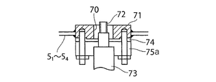
また、各収容部兼排出部51~54の下端部には、タンク本体部4の長手方向と交差する方向に対して予め定められた角度をなす位置に収容部兼排出部5に収容された危険物粉体Pに対して加圧気体を噴射する噴射口70がそれぞれ開口されている。各噴射口70は、図10(a)に示されるように、噴射口形成板71に開口されている。各噴射口形成板71には、図10(a)に示されるように、噴射口70から各収容部兼排出部51~54の内部に挿入され、加圧気体を噴射する円筒形状のフィルター部材72が挿入された状態で取り付けられている。フィルター部材72は、高圧窒素ガスを供給する第2の供給管73の先端に気密状に取り付けられている。第2の供給管73の先端は、パッキン74を介して噴射口形成板71に固定した状態で取り付けられた連結部材75aに固定されている。
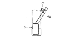
第2の供給管73は、図5に示されるように、タンク本体部4を平面的に見た左側面に沿って前方へ向けて水平方向に配置された供給管76に接続されている。第2の供給管73と供給管76との間には、それぞれ開閉弁75が設けられている。供給管76は、図10(b)に示されるように、第3の収容部兼排出部53と第4の収容部兼排出部54の間において、コンテナフレーム3に内方へ向けて傾斜した状態で取り付けられた支持部材78により支持されている。
供給管76の先端部には、タンク本体部4のフロント側において拡径された大径部76aが設けられている。供給管76の大径部76aは、図1(a)に示されるように、更にその先端部が下方へ向けて折り曲げられており、下方へ向けて折り曲げられた先端に第3の供給弁79が水平方向へ向けて接続されている。
なお、第2の供給弁68のリア側は、図1(a)に示されるように、上方へ向けて折り曲げられており、供給管76の大径部76aに接続されている。そのため、第3の供給弁79から供給される高圧窒素ガスは、供給管76の大径部76aへ供給された後、当該供給管76の大径部76aを介して第2の供給弁68へ供給され、第2の供給弁68、導入管67及び逆止弁66を介して排出管65へと供給される。
タンク本体部4の外周面は、断熱部6を構成する断熱材80(図11参照)により被覆されている。断熱材としては、ウレタンフォーム、ポリスチレンフォーム、ポリエチレンフォーム、グラスフォーム、ロックフォームなど材質によって種々のものを使用することが可能であるが、断熱性の点でウレタンフォームを使用することが望ましい。この実施の形態1では、厚さ100mmのウレタンフォームを使用している。
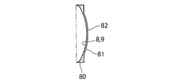
また、タンク本体部4の鏡板8,9の表面は、図11に示されるように、強度を考慮して厚さ25mmのガラスウール81を使用しており、当該ガラスウール81の表面は、アルミニウム製のフィルム82で被覆されている。
タンク本体部4の上端面には、図12に示されるように、マンホール16やボールバルブ24等の開口部を覆うスピルボックス部91~94が設けられている。各スピルボックス部91~94は、ステンレス等の金属板により上端面が開口された平面矩形状の枠体として構成されている。また、各スピルボックス部91~94の上端面には、開閉可能なカバーがそれぞれ設けられている。各スピルボックス部91~94の外周面は、断熱材83によって被覆されている。
各スピルボックス部91~94には、図11及び図12に示されるように、それぞれ排液管95~98が接続されている。タンク本体部4の左右両側にそれぞれ排液管95~98が接続されている。排液管95~98の先端は、排液管99に接続されており、排液管99の先端は、タンク本体部4のリア側の両側面に下方へ向けて配置されている。
タンク本体部4を固定するコンテナフレーム3は、図13に示されるように、直方体形状の枠体状に形成されている。コンテナフレーム3は、上述したように、20フィートコンテナの場合、長さが6058mm、幅が2438mm,高さが2591mmにそれぞれ設定されている。
コンテナフレーム部3は、タンクコンテナの長手方向に沿ったフロント側の端面とリア側の端面をそれぞれ構成する矩形状の枠体101,102と、フロント側及びリア側の枠体を連結する梁部材103とを備えている。
なお、コンテナフレーム3としては、フルフレームタイプに限られるものではなく、フレームの先端をタンク本体部の表面に結合したビームタイプを採用しても良い。
コンテナフレーム3の上端面には、図14に示されるように、作業者がタンクコンテナ1の上部に上がって作業を行うウオークプレート110が設けられている。ウオークプレート110は、コンテナフレーム3の上端面において、各スピルボックス部91~94とコンテナフレーム部3との間に配置されている。
<タンクコンテナの動作>
この実施の形態1に係るタンクコンテナ1では、次のようにして、危険物粉体Pが空気中の水分と接触したり温度が上昇するのを抑制しつつ輸送可能であり、危険物粉体Pの排出も容易に行うことが可能となっている。
この実施の形態1に係るタンクコンテナ1では、次のようにして、危険物粉体Pが空気中の水分と接触したり温度が上昇するのを抑制しつつ輸送可能であり、危険物粉体Pの排出も容易に行うことが可能となっている。
まず、タンクコンテナ1のタンク本体部4の内部に危険物粉体Pを収容するには、図1に示されるように、タンク本体部4の底部の各開閉弁62を閉じた状態で、各供給口22からタンク本体部4の内部に供給弁23を介して危険物粉体Pを供給することで、4つの収容部兼排出部51~54及びタンク本体部4の内部空間に危険物粉体Pが収容される。危険物粉体Pの収容率としては、4つの収容部兼排出部51~54及びタンク本体部4の内部空間の容積(約13KL)を100とした場合、85~95%程度に設定される。なお、4つの収容部兼排出部51~54及びタンク本体部4の内部空間に危険物粉体Pを収容した後、図5に示されるように、導入口25から供給管29,30を介して窒素ガスを内部に導入し、タンク本体部4の内部に残存した空気を窒素ガスと置換するように構成しても良い。
その際、供給管29,30には、第1の供給弁31を介して加圧窒素ガスが供給される。
タンクコンテナ1は、危険物粉体Pの収容作業が終了した後、供給弁23及び導入口25を閉じることで気密状態に保持される。そのため、タンク本体部4の内部に収容された危険物粉体Pは、収容時(保管時を含む)及び搬送時に外部の空気と接触することがない。したがって、危険物粉体Pが六フッ化リン酸リチウム等からなる場合であっても、次の化学式に示されるように、六フッ化リン酸リチウム等からなる粉体が外部の水分を含む空気と接触して急速に加水分解され、極めて毒性や腐蝕性が高いフッ化水素を生成することが確実に防止される。
LiPF6+4H2O
→LiF(フッ化リチウム)+5HF(フッ化水素)+H3PO4(リン酸)
LiPF6+4H2O
→LiF(フッ化リチウム)+5HF(フッ化水素)+H3PO4(リン酸)
また、タンクコンテナ1は、タンク本体部4の外周が断熱材80(図11参照)としてのウレタンフォームによって被覆されている。そのため、タンクコンテナ1は、外気温が上昇した場合においても、当該外気温が図示しない断熱材で遮蔽され熱がタンク本体部4の内部へ伝わるのを抑制することができ、タンク本体部4内の温度上昇が抑制される。そのため、危険物粉体Pとして六フッ化リン酸リチウム等を収容した場合でも、当該危険物粉体Pの温度を当初の環境温度である比較的低い温度に維持することができ、熱分解を起こすことが防止される。
次に、タンクコンテナ1において、積載物である危険物粉体Pを排出する原理と、積載物である危険物粉体Pを排出する際の操作手順について説明する。
タンクコンテナ1は、上述したように、4つの収容部兼排出部51~54及びタンク本体部4の内部空間に危険物粉体Pが収容される。4つの収容部兼排出部51~54及びタンク本体部4の内部空間に危険物粉体Pは、4つの収容部兼排出部51~54が略円錐形状に形成されているため、各収容部兼排出部51~54の下端部に設けられた排出弁62を解放することによって重力により排出される。
タンクコンテナ1は、危険物粉体Pを貯蔵乃至輸送した後、危険物粉体Pを外部に排出するには、図5に示されるように、排出管65の先端を図示しない外部の収容容器に接続した後、各排出弁62を開放するとともに、第2の供給弁79から加圧気体として加圧した窒素ガスを供給する動作が行われる。
このとき、各排出弁62を開放する順番は、特に限定されないが、例えば、タンク本体部4の最も下流側に位置する第4の収容部兼排出部54から上流側の第3、第2及び第1の収容部兼排出部53~51の順に各排出弁62を開放してくのが望ましい。
タンク本体部4の最も下流側に位置する第4の収容部兼排出部54の第4の排出弁62を最初に開放することにより、当該第4の収容部兼排出部54の第4の排出弁62から排出される危険物粉体Pを、第3の供給弁79から導入される加圧気体によって補助しつつ排出管65の排出口から確実に排出することができる。
その後、タンク本体部の第3の収容部兼排出部53の第3の排出弁62を開放することにより、当該第3の収容部兼排出部53の第3の排出弁62から排出される危険物粉体Pを、導入される加圧気体によって補助しつつ排出管65の排出口から確実に排出することができる。
次に、タンク本体部の第2の収容部兼排出部52の第2の排出弁62を開放することにより、当該第2の収容部兼排出部52の第2の排出弁62から排出される危険物粉体Pを、導入される加圧気体によって補助しつつ排出管65の排出口から確実に排出することができる。
そして、最後にタンク本体部4の第1の収容部兼排出部51の第1の排出弁62を開放することにより、当該第1の収容部兼排出部51の第1の排出弁62から排出される危険物粉体Pを、導入される加圧気体によって補助しつつ排出管65の排出口から確実に排出することができる。
また、これに限定されるものではなく、第1乃至第4の収容部兼排出部51~54の各排出弁62を同時に開放して、危険物粉体Pを排出管65の排出口から排出しても勿論良い。
いずれの場合においても、第1乃至第4の収容部兼排出部51~54内の危険物粉体Pの残量がある程度少なくなった状態で、開閉弁75を開放することにより、図10(a)に示されるように、第1乃至第4の収容部兼排出部51~54の底部の近傍に開口された各噴射口70からフィルター部材72を介して高圧窒素ガスを第2の供給管73から噴射させることにより、第1乃至第4の収容部兼排出部51~54の底部の近傍に危険物粉体Pが残存するのを効果的に防止乃至抑制することができる。
タンクコネテナ1は、上記動作機構を有する構造をもつことから、高い気密性を有することができる。気密性の目安となるタンクコンテナ1の内部のガスのリークレートは、タンクコンテナ1の内部に一定圧力のガス(空気、窒素、ヘリウム等の不活性ガス)を封入し、一定時間経過した際の圧力変化と温度変化から確認することができる。
本実施の形態に係るタンクコネテナ1のリークレートを求めたところ、5.2×10⁻⁵Pa・m3/secであり、気密状態の基準である1.0×10-4 Pa・m3/sec以下であることから、危険物粉体Pが空気中の水分と接触することを抑制しつつ輸送でき、危険物粉体Pの排出も容易に行うことが可能となっている。その結果、高付加価値危険物粉体の大量輸送(有効容積11.3KL)が可能となる。
1…タンクコンテナ
2…タンク
3…コンテナフレーム
4…タンク本体部
51~54…第1乃至第4の収容部兼排出部
7…円筒部
8,9…鏡板
2…タンク
3…コンテナフレーム
4…タンク本体部
51~54…第1乃至第4の収容部兼排出部
7…円筒部
8,9…鏡板
Claims (11)
- 内部に粉体が収容され、長手方向に沿った両端が閉塞された気密な円筒形状に形成されるタンク本体部と、
前記タンク本体部内の下部に長手方向に沿って互いに隣接するよう配置され、上端部が前記タンク本体の内壁及び隣接部同士と気密に接合されるとともに、下端部が前記タンク本体部の外周面に設けられた複数の開口から外部へ向けてそれぞれ突出するよう下向きの錐形状に形成される複数の収容部兼排出部と、
前記タンク本体部の外周面に設けられる断熱部と、
前記タンク本体部が固定されるコンテナフレーム部と、
を備えるタンクコンテナ。 - 前記タンク本体部の内周面は、前記タンク本体部の長手方向に沿って互いに隣接する前記複数の収容部兼排出部の間に配置された環状又は一部に切欠きを有する環状の補強部材により補強されている請求項1に記載のタンクコンテナ。
- 前記複数の収容部兼排出部は、その傾斜角が前記粉体の安息角以上に設定されている請求項1に記載のタンクコンテナ。
- 前記タンク本体部の上端部には、前記タンク本体部内に加圧気体を導入する導入口が長手方向に沿って1つ以上設けられている請求項1に記載のタンクコンテナ。
- 前記タンク本体部の上端部には、前記複数の収容部兼排出部に前記粉体を供給する供給口が前記複数の収容部兼排出部に対応してそれぞれ設けられている請求項1に記載のタンクコンテナ。
- 前記複数の収容部兼排出部の下端部には、前記複数の収容部兼排出部に収容された前記粉体に対して加圧気体を噴射する噴射口がそれぞれ設けられている請求項1に記載のタンクコンテナ。
- 前記複数の収容部兼排出部は、下向きの円錐形状に形成され、下端部に前記粉体を排出する排出口が開口されているとともに、前記排出口は、ボールバルブからなる排出弁により開閉される請求項1に記載のタンクコンテナ。
- 前記複数の収容部兼排出部は、前記タンク本体部の長手方向と交差する方向に沿った平面で半円錐形状に分割された2つの各構成部材を、前記タンク本体部の内部で互いに接合することにより円錐形状に形成される請求項7に記載のタンクコンテナ。
- 前記タンク本体部には、その長手方向に沿った両端部に環状に形成された取付部材がそれぞれ固定され、
前記タンク本体部は、前記取付部材を介して前記コンテナフレーム部に固定されている請求項1に記載のタンクコンテナ。 - 前記タンク本体部の上端部には、当該タンク本体部の上端部に設けられた開口部の外周を囲むよう平面矩形の枠体状に形成されたスピルボックス部が設けられ、前記スピルボックス部の外側面は、断熱材によって被覆されている請求項1に記載のタンクコンテナ。
- 少なくとも一方の端部が開口された円筒形状のタンク本体部を形成する第1の工程と、
前記タンク本体部内の下部に長手方向に沿って互いに隣接するよう配置され、上端部が前記タンク本体の内壁及び隣接部同士と気密に接合されるとともに、下端部が前記タンク本体部の外周面に設けられた開口から外部へ向けて突出するよう下向きの円錐形状に形成される複数の収容部兼排出部であって、前記複数の収容部兼排出部を前記タンク本体部の長手方向と交差する平面で半円錐形状に分割した2つの各構成部材を形成する第2の工程と、
前記2つの各構成部材を前記タンク本体部の内部に搬入し、前記タンク本体部の内部において前記2つの各構成部材を接合して前記複数の収容部兼排出部を形成する第3の工程と、
を備えるタンクコンテナの製造方法。
Priority Applications (4)
| Application Number | Priority Date | Filing Date | Title |
|---|---|---|---|
| US17/909,138 US20230095177A1 (en) | 2020-04-06 | 2021-04-05 | Tank container and method for manufacturing same |
| EP21785004.9A EP4134343A4 (en) | 2020-04-06 | 2021-04-05 | TANK TANKS AND METHOD FOR MANUFACTURING SAME |
| CN202180026389.5A CN115298114A (zh) | 2020-04-06 | 2021-04-05 | 罐容器及其制造方法 |
| KR1020227031708A KR20220155992A (ko) | 2020-04-06 | 2021-04-05 | 탱크 컨테이너 및 그 제조 방법 |
Applications Claiming Priority (2)
| Application Number | Priority Date | Filing Date | Title |
|---|---|---|---|
| JP2020-068032 | 2020-04-06 | ||
| JP2020068032A JP7362539B2 (ja) | 2020-04-06 | 2020-04-06 | タンクコンテナ及びその製造方法 |
Publications (1)
| Publication Number | Publication Date |
|---|---|
| WO2021206043A1 true WO2021206043A1 (ja) | 2021-10-14 |
Family
ID=78021645
Family Applications (1)
| Application Number | Title | Priority Date | Filing Date |
|---|---|---|---|
| PCT/JP2021/014465 Ceased WO2021206043A1 (ja) | 2020-04-06 | 2021-04-05 | タンクコンテナ及びその製造方法 |
Country Status (6)
| Country | Link |
|---|---|
| US (1) | US20230095177A1 (ja) |
| EP (1) | EP4134343A4 (ja) |
| JP (1) | JP7362539B2 (ja) |
| KR (1) | KR20220155992A (ja) |
| CN (1) | CN115298114A (ja) |
| WO (1) | WO2021206043A1 (ja) |
Families Citing this family (4)
| Publication number | Priority date | Publication date | Assignee | Title |
|---|---|---|---|---|
| JP7607575B2 (ja) | 2019-03-04 | 2024-12-27 | グッドパック アイビーシー (シンガポール) ピーティーイー リミテッド | 貨物ユニット |
| AU2020278208B2 (en) | 2019-05-17 | 2025-11-20 | Goodpack IBC (Singapore) Pte Ltd. | Shipping containers |
| MX2023005152A (es) | 2020-11-03 | 2023-08-01 | Goodpack Ibc Singapore Pte Ltd | Cajón de embalaje plegable. |
| KR20250131782A (ko) | 2022-12-29 | 2025-09-03 | 굿팩 아이비씨 (싱가포르) 피티이. 엘티디. | 접이식 상자 및 관련 방법 |
Citations (5)
| Publication number | Priority date | Publication date | Assignee | Title |
|---|---|---|---|---|
| JP2004090957A (ja) * | 2002-08-30 | 2004-03-25 | Kayaba Ind Co Ltd | 粉粒体運搬車 |
| JP2004263803A (ja) * | 2003-03-03 | 2004-09-24 | Mitsui Eng & Shipbuild Co Ltd | ガスハイドレート貯蔵タンク |
| JP2010132306A (ja) * | 2008-12-03 | 2010-06-17 | Qc:Kk | 液体輸送用コンテナ |
| JP2015501752A (ja) * | 2011-11-22 | 2015-01-19 | ハイル トレーラー インターナショナル カンパニー | トレーラーの車台フェアリング |
| JP2015093734A (ja) * | 2013-11-14 | 2015-05-18 | オーシーアイ カンパニー リミテッド | 粉体移送用コンテナ |
Family Cites Families (9)
| Publication number | Priority date | Publication date | Assignee | Title |
|---|---|---|---|---|
| BE761884A (nl) * | 1971-01-22 | 1971-07-01 | Hool & Zonen P V B A Van | Verbeteringen aan laadtanks voor het vervoer, langs de baan, van stortgoederen. |
| US5353967A (en) * | 1993-04-20 | 1994-10-11 | Northbrook Rail Corporation | Dry bulk pressure differential container |
| CN2167060Y (zh) * | 1993-08-07 | 1994-06-01 | 王建超 | 粉粒体罐式容器 |
| US5960974A (en) * | 1996-10-03 | 1999-10-05 | Advance Engineered Products Ltd. | Intermodal bulk container |
| GB0229252D0 (en) | 2002-12-16 | 2003-01-22 | Clyde Blowers Ltd | Transport and pneumatic conveying of bulk powders |
| JP2004276982A (ja) * | 2003-03-17 | 2004-10-07 | Showa Koki Kk | 粉体貯留装置 |
| JP4334304B2 (ja) * | 2003-09-03 | 2009-09-30 | 日曹エンジニアリング株式会社 | 粉体輸送方法及び輸送装置 |
| US20070071590A1 (en) * | 2005-09-21 | 2007-03-29 | Podd Stephen D | Spillbox system for a shipping container |
| US9903505B2 (en) * | 2016-06-03 | 2018-02-27 | Hoover Materials Handling Group, Inc. | Remote operated valves for ISO containers |
-
2020
- 2020-04-06 JP JP2020068032A patent/JP7362539B2/ja active Active
-
2021
- 2021-04-05 WO PCT/JP2021/014465 patent/WO2021206043A1/ja not_active Ceased
- 2021-04-05 US US17/909,138 patent/US20230095177A1/en active Pending
- 2021-04-05 CN CN202180026389.5A patent/CN115298114A/zh active Pending
- 2021-04-05 KR KR1020227031708A patent/KR20220155992A/ko active Pending
- 2021-04-05 EP EP21785004.9A patent/EP4134343A4/en active Pending
Patent Citations (5)
| Publication number | Priority date | Publication date | Assignee | Title |
|---|---|---|---|---|
| JP2004090957A (ja) * | 2002-08-30 | 2004-03-25 | Kayaba Ind Co Ltd | 粉粒体運搬車 |
| JP2004263803A (ja) * | 2003-03-03 | 2004-09-24 | Mitsui Eng & Shipbuild Co Ltd | ガスハイドレート貯蔵タンク |
| JP2010132306A (ja) * | 2008-12-03 | 2010-06-17 | Qc:Kk | 液体輸送用コンテナ |
| JP2015501752A (ja) * | 2011-11-22 | 2015-01-19 | ハイル トレーラー インターナショナル カンパニー | トレーラーの車台フェアリング |
| JP2015093734A (ja) * | 2013-11-14 | 2015-05-18 | オーシーアイ カンパニー リミテッド | 粉体移送用コンテナ |
Non-Patent Citations (1)
| Title |
|---|
| See also references of EP4134343A4 * |
Also Published As
| Publication number | Publication date |
|---|---|
| EP4134343A4 (en) | 2024-05-29 |
| JP7362539B2 (ja) | 2023-10-17 |
| US20230095177A1 (en) | 2023-03-30 |
| CN115298114A (zh) | 2022-11-04 |
| JP2021165148A (ja) | 2021-10-14 |
| EP4134343A1 (en) | 2023-02-15 |
| KR20220155992A (ko) | 2022-11-24 |
Similar Documents
| Publication | Publication Date | Title |
|---|---|---|
| JP7362539B2 (ja) | タンクコンテナ及びその製造方法 | |
| KR101953943B1 (ko) | 저장 탱크 봉쇄 시스템 | |
| US9175806B2 (en) | Storage tank containment system | |
| KR101358630B1 (ko) | 저장 탱크 격납 장치 | |
| JP6399409B2 (ja) | 薬液収納容器およびそのドライエア置換方法 | |
| US20160290564A1 (en) | High conformal pressure vessel | |
| US20080087665A1 (en) | Freight container | |
| US20140130914A1 (en) | Gas tank container | |
| TW571045B (en) | Transportation and storage of ultra-high purity products | |
| CN108328091B (zh) | 用于箔衬里fibc(散装袋)的气密密封件 | |
| JP2011056988A (ja) | ポリマーペレットの水上輸送方法 | |
| JPH04109025U (ja) | 化学薬品用搬送容器 | |
| JP5953286B2 (ja) | 粉体移送用コンテナ | |
| CA3243284A1 (en) | Container and method for transporting and for storing a material sensitive to humidity and use of a container | |
| JP2011116160A (ja) | バラ積み船、バラ積み用バージ及び貨物倉の設計方法 | |
| KR101403621B1 (ko) | 액화천연가스 저장용기의 구조 및 제작방법 | |
| JP2023006008A (ja) | 加圧タンク | |
| CN115366159B (zh) | 一种应用在手套箱的过渡舱中的可移动物品舱及手套箱 | |
| JP2011111147A (ja) | バラ積み船、バラ積み用バージ及び貨物倉の設計方法 | |
| JP2002193380A (ja) | タンクコンテナ | |
| JP2016204031A (ja) | 液体排出方法 | |
| JP2013244984A (ja) | 薬品用大型タンク | |
| JP2011111148A (ja) | バラ積み船及びバラ積み用バージ | |
| WO2009100574A1 (zh) | 一种具有框架的罐体组件 |
Legal Events
| Date | Code | Title | Description |
|---|---|---|---|
| 121 | Ep: the epo has been informed by wipo that ep was designated in this application |
Ref document number: 21785004 Country of ref document: EP Kind code of ref document: A1 |
|
| NENP | Non-entry into the national phase |
Ref country code: DE |
|
| ENP | Entry into the national phase |
Ref document number: 2021785004 Country of ref document: EP Effective date: 20221107 |