WO2021209011A1 - 一种毛细管道环境传感器及其制备方法 - Google Patents
一种毛细管道环境传感器及其制备方法 Download PDFInfo
- Publication number
- WO2021209011A1 WO2021209011A1 PCT/CN2021/087542 CN2021087542W WO2021209011A1 WO 2021209011 A1 WO2021209011 A1 WO 2021209011A1 CN 2021087542 W CN2021087542 W CN 2021087542W WO 2021209011 A1 WO2021209011 A1 WO 2021209011A1
- Authority
- WO
- WIPO (PCT)
- Prior art keywords
- capillary channel
- transfer
- cavity
- substrate
- magnetic
- Prior art date
- Legal status (The legal status is an assumption and is not a legal conclusion. Google has not performed a legal analysis and makes no representation as to the accuracy of the status listed.)
- Ceased
Links
Images



Classifications
-
- G—PHYSICS
- G01—MEASURING; TESTING
- G01D—MEASURING NOT SPECIALLY ADAPTED FOR A SPECIFIC VARIABLE; ARRANGEMENTS FOR MEASURING TWO OR MORE VARIABLES NOT COVERED IN A SINGLE OTHER SUBCLASS; TARIFF METERING APPARATUS; MEASURING OR TESTING NOT OTHERWISE PROVIDED FOR
- G01D5/00—Mechanical means for transferring the output of a sensing member; Means for converting the output of a sensing member to another variable where the form or nature of the sensing member does not constrain the means for converting; Transducers not specially adapted for a specific variable
- G01D5/12—Mechanical means for transferring the output of a sensing member; Means for converting the output of a sensing member to another variable where the form or nature of the sensing member does not constrain the means for converting; Transducers not specially adapted for a specific variable using electric or magnetic means
- G01D5/14—Mechanical means for transferring the output of a sensing member; Means for converting the output of a sensing member to another variable where the form or nature of the sensing member does not constrain the means for converting; Transducers not specially adapted for a specific variable using electric or magnetic means influencing the magnitude of a current or voltage
- G01D5/16—Mechanical means for transferring the output of a sensing member; Means for converting the output of a sensing member to another variable where the form or nature of the sensing member does not constrain the means for converting; Transducers not specially adapted for a specific variable using electric or magnetic means influencing the magnitude of a current or voltage by varying resistance
-
- G—PHYSICS
- G01—MEASURING; TESTING
- G01D—MEASURING NOT SPECIALLY ADAPTED FOR A SPECIFIC VARIABLE; ARRANGEMENTS FOR MEASURING TWO OR MORE VARIABLES NOT COVERED IN A SINGLE OTHER SUBCLASS; TARIFF METERING APPARATUS; MEASURING OR TESTING NOT OTHERWISE PROVIDED FOR
- G01D5/00—Mechanical means for transferring the output of a sensing member; Means for converting the output of a sensing member to another variable where the form or nature of the sensing member does not constrain the means for converting; Transducers not specially adapted for a specific variable
- G01D5/12—Mechanical means for transferring the output of a sensing member; Means for converting the output of a sensing member to another variable where the form or nature of the sensing member does not constrain the means for converting; Transducers not specially adapted for a specific variable using electric or magnetic means
- G01D5/14—Mechanical means for transferring the output of a sensing member; Means for converting the output of a sensing member to another variable where the form or nature of the sensing member does not constrain the means for converting; Transducers not specially adapted for a specific variable using electric or magnetic means influencing the magnitude of a current or voltage
- G01D5/142—Mechanical means for transferring the output of a sensing member; Means for converting the output of a sensing member to another variable where the form or nature of the sensing member does not constrain the means for converting; Transducers not specially adapted for a specific variable using electric or magnetic means influencing the magnitude of a current or voltage using Hall-effect devices
-
- G—PHYSICS
- G01—MEASURING; TESTING
- G01H—MEASUREMENT OF MECHANICAL VIBRATIONS OR ULTRASONIC, SONIC OR INFRASONIC WAVES
- G01H11/00—Measuring mechanical vibrations or ultrasonic, sonic or infrasonic waves by detecting changes in electric or magnetic properties
- G01H11/02—Measuring mechanical vibrations or ultrasonic, sonic or infrasonic waves by detecting changes in electric or magnetic properties by magnetic means, e.g. reluctance
- G01H11/04—Measuring mechanical vibrations or ultrasonic, sonic or infrasonic waves by detecting changes in electric or magnetic properties by magnetic means, e.g. reluctance using magnetostrictive devices
-
- G—PHYSICS
- G01—MEASURING; TESTING
- G01L—MEASURING FORCE, STRESS, TORQUE, WORK, MECHANICAL POWER, MECHANICAL EFFICIENCY, OR FLUID PRESSURE
- G01L19/00—Details of, or accessories for, apparatus for measuring steady or quasi-steady pressure of a fluent medium insofar as such details or accessories are not special to particular types of pressure gauges
- G01L19/14—Housings
-
- G—PHYSICS
- G01—MEASURING; TESTING
- G01L—MEASURING FORCE, STRESS, TORQUE, WORK, MECHANICAL POWER, MECHANICAL EFFICIENCY, OR FLUID PRESSURE
- G01L9/00—Measuring steady of quasi-steady pressure of fluid or fluent solid material by electric or magnetic pressure-sensitive elements; Transmitting or indicating the displacement of mechanical pressure-sensitive elements, used to measure the steady or quasi-steady pressure of a fluid or fluent solid material, by electric or magnetic means
- G01L9/0041—Transmitting or indicating the displacement of flexible diaphragms
- G01L9/007—Transmitting or indicating the displacement of flexible diaphragms using variations in inductance
Definitions
- the embodiment of the present invention relates to the technical field of environmental parameter detection sensors, in particular to a capillary channel environmental sensor and a preparation method thereof.
- environmental sensors include a series of subdivisions such as temperature sensors, pressure sensors, displacement sensors, vibration sensors, microphones, etc.
- the chip design, material, process, and packaging structure of each subdivision area are quite different, and it is difficult to integrate multiple different types.
- Environmental sensors are integrated, or the integration process is complex; in addition, the current sensor chips such as pressure sensors, displacement sensors, vibration sensors, microphones, etc. are difficult to meet the needs of high signal-to-noise ratio and low power consumption.
- the embodiments of the present invention provide a capillary channel environmental sensor and a preparation method thereof.
- the difference in size between the transfer cavity and the capillary channel is used to convert a small displacement under a large volume into a significant displacement under a small volume; Equipped with multiple high-sensitivity materials as magnetic induction elements, the displacement changes are converted into resistance value changes through intermediate variables, such as changes in magnetic
- Environmental parameter sensors such as acoustic waves are manufactured on a single chip under the same process, which is conducive to the integration and miniaturization of environmental sensors, while ensuring the sensor's high signal-to-noise ratio and low power consumption.
- an embodiment of the present invention provides a capillary channel environmental sensor, including a transfer substrate and at least one magnetic induction element;
- the transfer substrate is provided with a transfer cavity and at least one capillary channel, the cross-sectional area of the transfer cavity is larger than the cross-sectional area of the capillary channel, and one end of the capillary channel is in communication with the transfer cavity;
- An elastic transmission diaphragm is arranged between the transmission cavity and the external measurement environment, and a transmission medium is arranged inside the transmission cavity;
- a positioning drop is arranged inside the capillary channel, the positioning drop is in close contact with the inner wall of the capillary channel, and the positioning drop is in close contact with the transfer medium.
- the minimum distance between the magnetic induction element and the capillary channel is less than the minimum distance between the magnetic induction element and the elastic transmission diaphragm.
- the capillary channel environmental sensor further includes a signal conversion material, at least part of the signal conversion material is disposed in the transfer medium; or, the signal conversion material is disposed in the positioning droplet, so
- the positioning droplet includes mercury, magnetic fluid, or a hydrophobic organic liquid capable of generating an induced magnetic field based on the flow of the positioning droplet.
- the signal conversion material includes a magnetic material, and the magnetic material is arranged in the transfer medium or in the positioning drop;
- the signal conversion material includes a non-magnetic metal material and an excitation coil
- the non-magnetic metal material is disposed in the transfer medium or in the positioning droplet
- the excitation coil is disposed on the transfer substrate
- the excitation coil is loaded with a radio frequency alternating current for driving the non-magnetic metal material to generate an induced eddy current, thereby generating an induced magnetic field.
- the communication end of the capillary channel and the external measurement environment is closed.
- the magnetic induction element includes one of anisotropic magnetoresistance, giant magnetoresistance, tunnel junction magnetoresistance, or Hall element.
- the capillary channel environmental sensor further includes a connecting lead and a contact electrode on the first side of the magnetic sensing element, and a passivation layer on the second side of the magnetic sensing element; the first side and the The second side is arranged oppositely;
- the connecting lead is electrically connected with the magnetic induction element, and the contact electrode is electrically connected with the connecting lead.
- a rigid cover layer is provided on the surface of the elastic transmission diaphragm on one side away from the transmission cavity.
- a vacuum cover is provided on the side of the elastic transmission diaphragm away from the transmission cavity, the vacuum cover and the elastic transmission diaphragm form a closed cavity, and the closed cavity is a vacuum sealed cavity Or seal the cavity with a known reference pressure;
- a mass block is arranged in the enclosed cavity, and the mass block is arranged on the surface of the elastic transmission diaphragm; or, the enclosed cavity is filled with a counterweight liquid.
- an embodiment of the present invention also provides a method for preparing a capillary channel environment sensor for preparing the capillary channel environment sensor according to the first aspect, and the preparation method includes:
- the cross-sectional area of the transfer cavity is larger than the cross-sectional area of the capillary channel, and one end of the capillary channel is in communication with the transfer cavity;
- a transfer medium is injected into the transfer cavity, a positioning drop is injected into the capillary channel, the positioning drop is in close contact with the inner wall of the capillary channel, and the positioning drop is in close contact with the transfer medium ;
- preparing a transfer cavity and at least one capillary channel in the transfer substrate includes:
- the depth of the capillary channel is greater than the thickness of the elastic transmission diaphragm
- the second surface of the transfer substrate is etched to obtain a transfer cavity, the transfer cavity penetrates the transfer substrate, and the transfer cavity communicates with the capillary channel; the second surface and the first One surface is arranged oppositely.
- preparing a magnetic induction element includes:
- the preparation method further includes:
- the carrier substrate on the surface of the transfer diaphragm is removed by etching.
- preparing at least one magnetic induction element on the surface of the carrier substrate includes:
- the method further includes:
- the carrier substrate is thinned and etched to expose a part of the connection lead, and a metal material is deposited on the exposed part of the connection lead to form a contact electrode.
- injecting a transfer medium into the transfer cavity includes:
- the second surface is disposed opposite to the first surface
- a transfer medium is injected into the transfer cavity.
- the capillary channel environment sensor and the preparation method thereof provided by the embodiment of the present invention are based on the Pascal principle by providing a transfer cavity and a capillary channel that communicate with each other in the transfer substrate, and further set the cross-sectional area of the transfer cavity to be larger than the cross-sectional area of the capillary channel.
- the sensor includes a magnetic induction element, so that by positioning the droplet movement, the displacement change can be converted into a resistance value change through an intermediate variable, such as a magnetic field change; the high sensitivity and low power consumption characteristics of the magnetic induction element can be used to realize the environmental temperature, pressure, displacement,
- Environmental parameter sensors such as vibration and sound wave are manufactured on a single chip under the same process, which is conducive to the integration and miniaturization of environmental sensors, while ensuring the sensor's high signal-to-noise ratio and low power consumption.
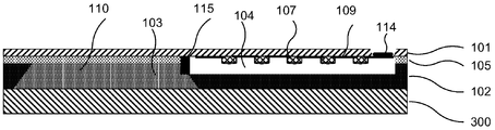
- FIG. 1 is a schematic diagram of a cross-sectional structure of a capillary channel environmental sensor according to an embodiment of the present invention
- FIG. 2 is a schematic diagram of a top view structure of a capillary channel environmental sensor according to an embodiment of the present invention
- FIG. 3 is a schematic cross-sectional structure diagram of another capillary channel environmental sensor provided by an embodiment of the present invention.
- FIG. 4 is a schematic top view of another capillary channel environmental sensor according to an embodiment of the present invention.
- FIG. 5 is a schematic cross-sectional structure diagram of another capillary channel environmental sensor provided by an embodiment of the present invention.
- FIG. 6 is a schematic cross-sectional structure diagram of another capillary channel environmental sensor provided by an embodiment of the present invention.
- FIG. 7 is a schematic cross-sectional structure diagram of another capillary channel environmental sensor provided by an embodiment of the present invention.
- FIG. 8 is a schematic cross-sectional structure diagram of another capillary channel environmental sensor provided by an embodiment of the present invention.
- FIG. 9 is a schematic cross-sectional structure diagram of another capillary channel environmental sensor provided by an embodiment of the present invention.
- FIG. 10 is a schematic cross-sectional structure diagram of another capillary channel environmental sensor provided by an embodiment of the present invention.
- FIG. 11 is a schematic flow chart of a method for preparing a capillary channel environmental sensor according to an embodiment of the present invention.
- FIG. 12 is a schematic flowchart of another method for preparing a capillary channel environmental sensor according to an embodiment of the present invention.
- 13-20 are specific preparation process diagrams of each step in the preparation method corresponding to FIG. 12.
- Fig. 1 is a schematic cross-sectional structure diagram of a capillary channel environmental sensor provided by an embodiment of the present invention
- Fig. 2 is a schematic top view structure diagram of a capillary channel environmental sensor provided by an embodiment of the present invention. As shown in Figs.
- the capillary channel environmental sensor 10 provided by the embodiment of the invention includes a transfer substrate 102 and at least one magnetic sensing element 107; the transfer substrate 102 is provided with a transfer cavity 103 and at least one capillary channel 104, and the cross-sectional area of the transfer cavity 103 is larger than that of the capillary channel 104 cross-sectional area, one end of the capillary channel 104 communicates with the transmission cavity 103; an elastic transmission diaphragm 105 is arranged between the transmission cavity 103 and the external measurement environment, and a transmission medium is arranged inside the transmission cavity 103; a positioning liquid is arranged inside the capillary channel 104 Drop 115, the positioning drop 115 is in close contact with the inner wall of the capillary channel 104, and the positioning drop is in close contact with the transfer medium.
- a transfer cavity 103 and a capillary channel 104 connected to each other are formed in the transfer substrate 102, and the cross-sectional area of the transfer cavity 103 is larger than the cross-sectional area 104 of the capillary channel;
- an elastic transmission diaphragm 105 is arranged between the transmission cavity 103 and the external measurement environment, and the transmission cavity 103 is filled with a transmission medium (not shown in the figure).
- the transmission medium is a liquid or gas with a force transmission effect.
- the capillary channel 104 is provided with a positioning drop 115, the positioning drop 115 is in close contact with the inner wall of the capillary channel 104, and the positioning drop 115 is in close contact with the transfer medium.
- the force is transmitted to the capillary channel 104 with a smaller cross-sectional area through the transmission medium.
- the difference between the cross-sectional area of the transmission cavity 103 and the capillary channel 104 The huge difference, magnifying the small displacement in a large area into a significant displacement in a small area, magnifies the changes in the external environment.
- the capillary channel environmental sensor 10 further includes a magnetic induction element 107, so that the significant displacement in the capillary channel 104 drives the positioning drop 115 to move, which will cause the magnetic field of the magnetic induction element 107 to change.
- the magnetic induction element 107 can be a high-sensitivity magnetoresistive element.
- the displacement change is converted into the resistance value change through the intermediate variable, such as the magnetic field change; thus, the external pressure, vibration or sound wave signal can be accurately measured; at the same time, the high sensitivity and low power consumption characteristics of the magnetic induction element can be used to realize the pressure, displacement,
- Environmental parameter sensors such as vibration and sound waves are manufactured on a single chip under the same process, which is conducive to the realization of the integrated and miniaturized design of micro-motor environmental sensors, which is in line with the development trend of capillary channel environmental sensors.
- the positioning drop 115 may be one of mercury, magnetic fluid, or hydrophobic organic liquid.
- the capillary channel environment sensor 10 may include one or more capillary channels 104.
- FIGS. 1 and 2 only take the capillary channel environment sensor 10 including one capillary channel 104 as an example for illustration. The embodiment does not limit the specific number of capillary channels 104.
- the capillary channel environmental sensor provided by the embodiment of the present invention is based on the Pascal principle by providing a transfer cavity and a capillary channel that communicate with each other in the transfer substrate, and further set the cross-sectional area of the transfer cavity to be larger than the cross-sectional area of the capillary channel.
- a positioning droplet is set in the capillary channel, and the capillary channel environment sensor includes a magnetic sensing element, so that the movement is based on the positioning of the droplet Displacement changes can be converted into resistance value changes through intermediate variables, such as magnetic field changes; using the high sensitivity and low power consumption characteristics of magnetic induction elements, environmental parameter sensors such as pressure, displacement, vibration and sound waves can be manufactured on a single chip under the same process , Which is conducive to the integration and miniaturization of environmental sensors, while ensuring the sensor's high signal-to-noise ratio and low power consumption.
- the capillary channel environmental sensor 10 may further include a signal conversion material, at least part of the signal conversion material is disposed in a transmission medium, or the signal conversion material is disposed in a positioning drop 115, and the positioning drop includes mercury.
- a signal conversion material Magnetic fluid or hydrophobic organic liquid capable of generating an induced magnetic field based on the flow of the positioning droplets.
- the signal conversion material provided by the embodiment of the present invention may be a magnetic material with high magnetic permeability or large remanence.
- the signal conversion material in the embodiment of the present invention can have a variety of different setting modes.
- the specific setting mode of the signal conversion material will be described below.
- the signal conversion material may include a magnetic material 110, and the magnetic material 110 is disposed in a transmission medium.
- the displacement of the magnetic material 110 is caused during the deformation of the diaphragm 105 through the elastic transmission, so that the magnetic field at the position of the magnetic induction element 107 changes correspondingly, thereby obtaining the environmental change parameters.
- the magnetic material 110 may be a magnetic metal material or a magnetic non-metal material, which is not limited in the embodiment of the present invention.
- the magnetic material 110 may be evenly dispersed in the transfer medium in the form of particles, or may be arranged in the transfer medium in other forms, for example, in the form of a magnetic film. The embodiment of the present invention does not limit the arrangement of the magnetic material 110. 1 and 2 only take the magnetic material 110 in the form of particles evenly dispersed in the transfer medium as an example for illustration.
- Fig. 3 is a schematic cross-sectional structure diagram of another capillary channel environmental sensor provided by an embodiment of the present invention
- Fig. 4 is a schematic top view structure diagram of another capillary channel environmental sensor provided by an embodiment of the present invention, as shown in Figs. 3 and 4
- the signal conversion material includes a non-magnetic metal material 111 and an excitation coil 112.
- the non-magnetic metal material 111 is arranged in the transmission medium, and the excitation coil 112 is arranged on the transmission substrate 102; the excitation coil 106 is loaded with a radio frequency alternating current for driving the non-magnetic
- the magnetic metal material 111 generates an induced eddy current, thereby generating an induced magnetic field.
- FIG. 3 takes the excitation coil 112 arranged in the capillary channel 104 as an example for description
- FIG. 4 takes the excitation coil 112 and the outside of the capillary channel 104 as an example for description.
- the non-magnetic metal particles 111 by loading a radio frequency alternating current in the excitation coil 112, the non-magnetic metal particles 111 generate an induced eddy current, thereby generating an induced magnetic field, and then the non-magnetic metal particles 111 are displaced to make the magnetic induction element 107 position
- the magnetic field changes accordingly, and the environmental change parameters are obtained.
- the non-magnetic metal material 111 may be evenly dispersed in the transmission medium in the form of particles, or may be disposed in the transmission medium in other forms, for example, in the form of a non-magnetic film.
- the arrangement method of is not limited.
- FIGS. 3 and 4 only take the non-magnetic metal material 111 in the form of particles evenly and dispersedly arranged in the transfer medium as an example for illustration.
- FIG. 5 is a schematic cross-sectional structure diagram of another capillary channel environmental sensor provided by an embodiment of the present invention.
- the signal conversion material is disposed in the positioning drop 115, and the excitation coil 112 is disposed on the transfer substrate 102;
- a radio frequency alternating current is loaded in 106 to drive the non-magnetic metal material 111 to generate an induced eddy current, thereby generating an induced magnetic field.
- the positioning liquid drop 115 includes mercury, magnetic fluid, or a hydrophobic organic liquid capable of generating an induced magnetic field based on the flow of the positioning liquid drop 115.
- the positioning liquid drop 115 By loading a radio frequency alternating current in the excitation coil 112, the positioning liquid drop 115 generates an induced eddy current, thereby generating an induced magnetic field, and then the displacement of the positioning liquid drop 115 causes the magnetic field at the position of the magnetic induction element 107 to correspondingly change, thereby obtaining environmental change parameters.
- the various setting methods of the signal conversion material are described in detail above.
- the embodiment of the present invention does not limit the specific setting methods of the signal conversion material.
- the sensitivity of the capillary channel environmental sensor is sufficient.
- the magnetic induction element 107 may include one of anisotropic magnetoresistance, giant magnetoresistance, tunnel junction magnetoresistance, or Hall element. By setting the magnetic induction element 107 as a high-sensitivity magnetoresistive element, the micro The motor environment sensor can accurately measure the external environment temperature, pressure, vibration or sound wave signal. Continuing to refer to FIG. 1, the magnetic induction element 107 is disposed on the carrier substrate 101.
- the minimum distance between the magnetic induction element 107 and the capillary channel 104 is less than the minimum distance between the magnetic induction element 107 and the elastic transmission diaphragm 105, so as to ensure that each magnetic induction element 107 can Detecting the movement of the positioning drop in the capillary channel 104 ensures that the signal sensed by the magnetic induction element 107 changes greatly, and improves the sensing sensitivity of the micro-motor environment sensor.
- the embodiment of the present invention does not limit the location of the magnetic induction element 107. As shown in FIG. 1, FIG. 2, FIG. 3, and FIG. It is shown that if the magnetic induction element 107 is located outside the capillary channel 104, it is only necessary to ensure that the magnetic induction element 107 can sense changes in the external environment.
- FIG. 6 is a schematic cross-sectional structure diagram of another capillary channel environmental sensor provided by an embodiment of the present invention.
- the capillary channel environmental sensor 10 provided by the embodiment of the present invention is also It may include a connecting lead 109 and a contact electrode 114 on the first side of the magnetic induction element 107 and a passivation layer (not shown in the figure) on the second side of the magnetic induction element 107; the first side and the second side are arranged opposite to each other; the connecting lead 109 It is electrically connected to the magnetic induction element 107, and the contact electrode 114 is electrically connected to the connection lead 09.
- the magnetic sensing element 107 transmits signals to the contact electrode 114 through the connecting lead 109 to ensure that the signal induced by the magnetic sensing element 107 can be transmitted normally in time, and that the capillary channel environment sensor can sense external pressure, displacement, vibration and Environmental parameters such as sound waves ensure that the capillary channel environmental sensor can work normally. Further, by providing a passivation layer on the second side of the magnetic induction element 107, the passivation layer enhances the packaging and protection of the magnetic induction element 107, thereby increasing the service life of the magnetic induction element 107, thereby increasing the service life of the capillary channel environmental sensor.
- FIG. 7 is a schematic cross-sectional structure diagram of another capillary channel environment sensor provided by an embodiment of the present invention.
- the capillary channel 104 is connected to the measurement environment. The end is closed to ensure that the movement of the positioning drop 115 is only based on the changes in the external environment sensed on the side of the elastic transfer film 105, ensuring high sensitivity to external environmental changes and avoiding the interference of pollutants entering the capillary channel on the measurement.
- FIG. 8 is a schematic cross-sectional structure diagram of another capillary channel environment sensor provided by an embodiment of the present invention.
- the elastic transmission diaphragm in the capillary channel environment sensor 10 provided by the embodiment of the present invention A rigid cover layer 113 is provided on the side surface of 105 away from the transfer cavity 103.
- the elastic transmission diaphragm 105 of the capillary channel environment sensor 10 and the external environment are completely covered by the rigid covering layer 113.
- the displacement of the elastic transmission diaphragm 105 is only affected by the change in the volume of the transmission medium caused by temperature, and is not affected by external pressure. , Vibration and sound waves, etc., this design is used to measure the ambient temperature, to ensure that the capillary channel environmental sensor can realize the measurement of the ambient temperature, and to increase the scope of use of the capillary channel environmental sensor measurement.
- FIG. 9 is a schematic cross-sectional structure diagram of another capillary channel environmental sensor provided by an embodiment of the present invention
- FIG. 10 is a schematic cross-sectional structure diagram of another capillary channel environmental sensor provided by an embodiment of the present invention.
- a vacuum cover 201 is provided on the side of the elastic transmission diaphragm 105 away from the transmission cavity 103, and the vacuum cover 201 and the elastic transmission diaphragm 105 form a closed
- the enclosed cavity is a vacuum sealed cavity or a sealed cavity with a known reference pressure; a mass 200 is arranged in the enclosed cavity, and the mass 200 is arranged on the surface of the elastic transmission diaphragm 105; or, the enclosed cavity is filled with Heavy liquid (not shown in the figure).
- Figure 9 takes the capillary channel 104 and the measurement environment open as an example for illustration
- Figure 10 takes the capillary channel 104 and the measurement environment closed as an example for illustration; at the same time, Figures 9 and 10 take the closed cavity
- a mass block 200 is set as an example for description.
- Figs. 9 and 10 in order to improve the response of the elastic transmission diaphragm 105 to inertial parameters, as shown in Figs.
- a mass 200 and a vacuum cover 201 can be set above the elastic transmission diaphragm 105, and the vacuum cover 201
- the cavity formed by the elastic transmission diaphragm 105 should be vacuum sealed or set to a known reference pressure to eliminate the influence of external pressure changes, to ensure that the capillary channel environmental sensor can measure inertial parameters, and to increase the scope of use of the capillary channel environmental sensor measurement .
- an embodiment of the present invention also provides a method for preparing a capillary channel environment sensor, which is used to prepare the capillary channel environment sensor described in the foregoing embodiment of the present invention.
- FIG. 11 is a schematic flowchart of a method for preparing a capillary channel environment sensor according to an embodiment of the present invention. As shown in FIG. 11, the method for preparing a capillary channel environment sensor according to an embodiment of the present invention includes:
- an elastic transfer membrane can be grown on the first surface of the complete transfer substrate by a thermal oxidation method or a deposition method.
- At least one capillary channel is prepared by etching the elastic transmission diaphragm and the transmission substrate on the first surface of the transmission substrate, that is, the side where the elastic transmission diaphragm is grown.
- the depth of the capillary channel is greater than the thickness of the elastic transmission diaphragm and the capillary channel The bottom is located in the transfer substrate.
- the transfer substrate is etched on the second surface of the transfer substrate to prepare a transfer cavity, the transfer cavity portion is stopped on the lower surface of the elastic transfer diaphragm, and the transfer cavity is communicated with the capillary channel.
- the method for preparing the capillary channel environmental sensor is based on the Pascal principle by preparing a transfer cavity and a capillary channel that are communicated with each other in a transfer substrate, and further prepares the cross-sectional area of the transfer cavity to be larger than the cross-sectional area of the capillary channel.
- the volume difference between the transfer cavity and the capillary channel the small displacement under large volume is converted into significant displacement under small volume, and the significant displacement can be transmitted to the capillary channel; at the same time, positioning droplets and magnetic sensing elements are prepared in the capillary channel.
- the displacement change is converted into resistance value change through intermediate variables, such as magnetic field changes; using the high sensitivity and low power consumption characteristics of magnetic induction elements, it is possible to realize the sensor of environmental parameters such as environmental temperature, pressure, displacement, vibration and sound waves.
- Single-chip manufacturing under the same process is conducive to the integration and miniaturization of environmental sensors, while ensuring the sensor's high signal-to-noise ratio and low power consumption.
- FIG. 12 is a schematic flowchart of another method for preparing a capillary channel environment sensor according to an embodiment of the present invention. As shown in FIG. 12, the method for preparing a capillary channel environment sensor according to an embodiment of the present invention may include:
- an elastic transmission diaphragm 105 is grown on the first surface of the complete transmission substrate 102.
- S220 Prepare a transfer cavity and at least one capillary channel in the transfer substrate, the cross-sectional area of the transfer cavity is larger than the cross-sectional area of the capillary channel, and one end of the capillary channel is in communication with the transfer cavity.
- At least one capillary channel 104 is prepared by etching the elastic transmission diaphragm 105 and the transmission substrate 102 on the first surface of the transmission substrate 1020, that is, the side where the elastic transmission diaphragm 105 is grown.
- the depth of the capillary channel 104 is greater than The thickness of the elastic transmission diaphragm 105 and the bottom of the capillary channel are located in the transmission substrate 102.
- the second surface of the transfer substrate 102 is etched to prepare a transfer cavity 103.
- the transfer cavity 103 penetrates the transfer substrate 102, that is, the transfer cavity portion 103 stops on the lower surface of the elastic transfer diaphragm 105, and the transfer cavity 103
- the cavity 103 communicates with the capillary channel 104.
- the second surface of the transfer substrate and the first surface are arranged opposite to each other.
- injecting a transfer medium into the transfer cavity may include:
- the auxiliary wafer 300 is selected, and the auxiliary wafer 300 is bonded to the second surface of the transfer substrate 102 to obtain the transfer cavity 103, and the transfer medium is injected into the transfer cavity 103; at the same time, in the capillary channel 104
- the positioning drop 115 is injected, the positioning drop 115 is in close contact with the inner wall of the capillary channel 104, and the positioning drop 115 is in close contact with the transfer medium.
- S240 Select a carrier substrate and prepare at least one magnetic induction element on the surface of the carrier substrate, and bond the carrier substrate and the transfer substrate in a manner that the magnetic induction element faces the transfer substrate.
- the carrier substrate 101 is selected and a thin film of sensing material is deposited on the surface of the carrier substrate 101, and the magnetic sensing element 107 and the connecting lead 109 are formed by photolithography. Then, a passivation layer (not shown in the figure) is prepared on the side of the magnetic induction element 107 away from the supporting substrate 101 for passivation protection of the magnetic induction element 107.
- the carrier substrate 101 and the transfer substrate 102 are bonded in such a way that the magnetic induction element 107 faces the transfer substrate 102 to obtain at least one magnetic induction element 107.
- the carrier substrate 101 is thinned and etched from the side of the carrier substrate 101 away from the transfer substrate 102 to expose a part of the connecting lead 109.
- the exposed connecting lead 109 is partially deposited with a metal material to form a contact electrode 114.
- the carrier substrate 101 on the surface of the elastic transmission diaphragm 105 is etched and removed to obtain a capillary channel environment sensor.
- the capillary channel environment sensor can measure environmental parameters such as pressure, displacement, vibration, and acoustic waves.
- the above embodiments describe in detail the preparation method of the capillary channel environmental sensor from the perspective of the actual preparation process, and ensure that the prepared capillary channel environmental sensor can realize the sensor of environmental temperature, pressure, displacement, vibration, and sound wave.
- Single-chip manufacturing under the same process is conducive to the integration and miniaturization of environmental sensors, while ensuring the sensor's high signal-to-noise ratio and low power consumption.
- the method for preparing the capillary channel environmental sensor provided by the embodiment of the present invention further includes preparing a signal conversion material.
- the signal conversion material includes a magnetic material
- the preparation of the signal conversion material may include preparing a magnetic material in the transmission cavity, the magnetic material being arranged in the transmission medium or in the positioning drop;
- the signal conversion material includes non-magnetic metal materials and laser coils
- the preparation of the signal conversion material may include preparing a non-magnetic metal material in the transfer cavity or in the positioning drop, and the non-magnetic metal material is arranged in the transfer medium or in the positioning drop;
- An excitation coil is prepared on the transfer substrate, and a radio frequency alternating current is loaded in the excitation coil to drive the non-magnetic metal material to generate an induced eddy current, thereby generating an induced magnetic field.
- the signal conversion material may include different forms, and correspondingly, the preparation method corresponds to different processes.
- the signal conversion material By adding the signal conversion material, the amplitude of the intermediate variable change is increased, and the sensitivity of the capillary channel environmental sensor is improved. .
- the method for preparing the capillary channel environmental sensor may further include preparing a mass and a vacuum cover on the side of the elastic transmission diaphragm away from the transmission cavity, and the vacuum cover and the elastic transmission diaphragm form a closed Cavity, the closed cavity is a vacuum sealed cavity or a known reference pressure sealed cavity, the mass is set in the vacuum cover; or, the vacuum cover is prepared on the side of the elastic transmission diaphragm away from the transmission cavity, and the vacuum cover and elastic transmission
- the diaphragm forms a closed cavity, which is a vacuum sealed cavity or a known reference pressure sealed cavity, and the closed cavity is filled with a weight liquid.
Landscapes
- Physics & Mathematics (AREA)
- General Physics & Mathematics (AREA)
- Measuring Fluid Pressure (AREA)
- Micromachines (AREA)
- Transmission And Conversion Of Sensor Element Output (AREA)
Abstract
本发明实施例公开了一种毛细管道环境传感器及其制备方法,毛细管道环境传感器包括传递空腔和至少一个毛细管道,传递空腔的截面积大于毛细管道截面积,毛细管道的一端与传递空腔连通;传递空腔与外部测量环境之间设置有弹性传递隔膜;毛细管道内部设置有定位液滴,定位液滴与毛细管道内壁密合接触,且定位液滴与传递媒介密合接触。通过互连接的传递空腔和毛细管道,且传递空腔的截面积大于毛细管道的截面积,利用传递空腔与毛细管道的体积差异,将大体积下微小位移转化为小体积下显著位移;由于毛细管道中设置有定位液滴,且毛细管道环境传感器包括磁感应元件,磁感应元件基于定位液滴移动将位移变化通过中间变量,实现高灵敏度和低功耗检测。
Description
本发明实施例涉及环境参数检测传感器技术领域,特别涉及一种毛细管道环境传感器及其制备方法。
目前环境传感器包括温度传感器,压力传感器,位移传感器,振动传感器,麦克风等一系列细分领域,各细分领域芯片设计、材料、工艺、封装结构环节均有较大差异,难以将多个不同类环境传感器集成化,或集成工艺复杂;除此以外,目前压力传感器,位移传感器,振动传感器,麦克风等传感器芯片难以兼顾高信噪比和低功耗的需求。
发明内容
有鉴于此,本发明实施例提供一种毛细管道环境传感器及其制备方法,基于帕斯卡原理,利用传递空腔与毛细管道的尺寸差异,将大体积下微小位移转化为小体积下显著位移;适配多元高灵敏度材料作为磁感应元件,将位移变化通过中间变量,如磁场变化,转换为电阻值变化;同时利用磁感应元件的高灵敏度、低功耗特性,实现将环境温度、压力、位移、振动和声波等环境参数传感器在相同工艺下单芯片制造,有利于环境传感器一体化、小型化,同时保证传感器高信噪比,低功耗。
第一方面,本发明实施例提供了一种毛细管道环境传感器,包括传递基片以及至少一个磁感应元件;
所述传递基片内设置有传递空腔和至少一个毛细管道,所述传递空腔的截面积大于所述毛细管道截面积,所述毛细管道的一端与所述传递空腔连通;
所述传递空腔与外部测量环境之间设置有弹性传递隔膜,所述传递空腔内部设置传递媒介;
所述毛细管道内部设置有定位液滴,所述定位液滴与所述毛细管道内壁密合接触,且所述定位液滴与所述传递媒介密合接触。
在一些实施例中,所述磁感应元件距离所述毛细管道的最小距离小于所述磁感应元件距离所述弹性传递隔膜的最小距离。
在一些实施例中,所述毛细管道环境传感器还包括信号转换材料,至少部分所述信号转换材料设置于所述传递媒介中;或者,所述信号转换材料设置于所述定位液滴中,所述定位液滴包括水银、磁流体或者能够基于所述定位液滴的流动产生感应磁场的疏水性有机液体。
在一些实施例中,所述信号转换材料包括磁性材料,所述磁性材料设置于所述传递媒介中或者设置于所述定位液滴中;
或者,所述信号转换材料包括非磁性金属材料和激发线圈,所述非磁性金属材料设置于所述传递媒介中或者设置于所述定位液滴中,所述激发线圈设置于所述传递基片上;所述激发线圈内加载有射频交流电电流,用于驱动所述非磁性金属材料产生感应涡流,从而产生感应磁场。
在一些实施例中,所述毛细管道与所述外部测量环境的连通端封闭。
在一些实施例中,所述磁感应元件包括各向异性磁阻、巨磁阻、隧道结磁阻或者霍尔元件中的一种。
在一些实施例中,所述毛细管道环境传感器还包括位于所述磁感应元件第一侧的连接引线和接触电极以及位于所述磁感应元件第二侧的钝化层;所述第一侧和所述第二侧相对设置;
所述连接引线与所述磁感应元件电连接,所述接触电极与所述连接引线电连接。
在一些实施例中,所述弹性传递隔膜远离所述传递空腔的一侧表面设置有刚性覆盖层。
在一些实施例中,所述弹性传递隔膜远离所述传递空腔的一侧设置有真空罩,所述真空罩与所述弹性传递隔膜形成封闭空腔,所述封闭空腔为真空密封空腔或者已知参考压强密封空腔;
所述封闭空腔内设置有质量块,所述质量块设置于所述弹性传递隔膜表面;或者,所述封闭空腔内填充有配重液体。
第二方面,本发明实施例还提供了一种毛细管道环境传感器的制备方法,用于制备第一方面所述的毛细管道环境传感器,所述制备方法包括:
选取传递基片,在所述传递基片第一表面生长弹性传递隔膜;
在所述传递基片内制备传递空腔和至少一个毛细管道,所述传递空腔的截面积大于所述毛细管道截面积,所述毛细管道的一端与所述传递空腔连通;
在所述传递空腔内注入传递媒介,在所述毛细管道内注入定位液滴,所述定位液滴与所述毛细管道内壁密合接触,且所述定位液滴与所述传递媒介密合接触;
制备磁感应元件。
在一些实施例中,在所述传递基片内制备传递空腔和至少一个毛细管道,包括:
刻蚀所述弹性传递隔膜和所述传递基板制备得到至少一根毛细管道,所述毛细管道的深度大于所述弹性传递隔膜的厚度;
刻蚀所述传递基片的第二表面得到传递空腔,所述传递空腔贯穿所述传递基片,且所述传递空腔与所述毛细管道连通;所述第二表面与所述第一表面相对设置。
在一些实施例中,制备磁感应元件,包括:
选取承载基片并在所述承载基片表面制备至少一个磁感应元件;
以所述磁感应元件朝向所述传递基片的方式键合所述承载基片和所述传递基片;
所述制备方法还包括:
刻蚀去除所述传递隔膜表面的所述承载基片。
在一些实施例中,在所述承载基片表面制备至少一个磁感应元件,包括:
在所述承载基片表面沉积感应材料薄膜,光刻形成磁感应元件及连接引线;
在所述磁感应元件远离所述承载基片的一侧制备钝化层;
在所述承载基片表面制备至少一个磁感应元件之后,还包括:
从所述承载基片远离所述传递基板的一侧减薄并刻蚀所述承载基片至露出部分所述连接引线,在露出的所述连接引线部分沉积金属材料形成接触电极。
在一些实施例中,在所述传递空腔内注入传递媒介,包括:
选取辅助晶圆;
将所述辅助晶圆与所述传递基片的第二表面键合得到所述传递空腔;所述第二表面与所述第一表面相对设置;
在所述传递空腔内注入传递媒介。
本发明实施例提供的毛细管道环境传感器及其制备方法,通过在传递基片中设置相互连通的传递空腔和毛细管道,进一步设置传递空腔的截面积大于毛细管道的截面积,基于帕斯卡原理,利用传递空腔间与毛细管道的体积差异,将大体积下微小位移转化为小体积下显著位移,并且可以将显著位移传导至毛细管道;同时在毛细管道中设置定位液滴,且毛细管道环境传感器包括磁感应元件,如此可以通过定位液滴移动将位移变化通过中间变量,如磁场变化,转换为电阻值变化;利用磁感 应元件的高灵敏度、低功耗特性,实现将环境温度、压力、位移、振动和声波等环境参数传感器在相同工艺下单芯片制造,有利于环境传感器一体化、小型化,同时保证传感器高信噪比,低功耗。
通过阅读参照以下附图所作的对非限制性实施例所作的详细描述,本发明的其它特征、目的和优点将会变得更明显:
图1是本发明实施例提供的一种毛细管道环境传感器的剖面结构示意图;
图2是本发明实施例提供的一种毛细管道环境传感器的俯视结构示意图;
图3是本发明实施例提供的另一种毛细管道环境传感器的剖面结构示意图;
图4是本发明实施例提供的另一种毛细管道环境传感器的俯视结构示意图;
图5是本发明实施例提供的另一种毛细管道环境传感器的剖面结构示意图;
图6是本发明实施例提供的另一种毛细管道环境传感器的剖面结构示意图
图7是本发明实施例提供的另一种毛细管道环境传感器的剖面结构示意图;
图8是本发明实施例提供的另一种毛细管道环境传感器的剖面结构示意图
图9是本发明实施例提供的另一种毛细管道环境传感器的剖面结构示意图
图10是本发明实施例提供的另一种毛细管道环境传感器的剖面结构示意图;
图11是本发明实施例提供的一种毛细管道环境传感器的制备方法的流程示意图;
图12是本发明实施例提供的另一种毛细管道环境传感器的制备方法的流程示意图;
图13-图20是图12对应的制备方法中各个步骤的具体制备工艺图。
为使本发明的目的、技术方案和优点更加清楚,以下将结合本发明实施例中的附图,通过具体实施方式,完整地描述本发明的技术方案。显然,所描述的实施例是本发明的一部分实施例,而不是全部的实施例,基于本发明的实施例,本领域普通技术人员在没有做出创造性劳动的前提下获得的所有其他实施例,均落入本发明的保护范围之内。
图1是本发明实施例提供的一种毛细管道环境传感器的剖面结构示意图,图2是本发明实施例提供的一种毛细管道环境传感器的俯视结构示意图,如图1和图2所示,本发明实施例提供的毛细管道环境传感器10包括传递基片102以及至少一个磁感应元件107;传递基片102内设置有传递空腔103和至少一个毛细管道104,传递空腔103的截面积大于毛细管道104截面积,毛细管道104的一端与传递空腔103连通;传递空腔103与外部测量环境之间设置有弹性传递隔膜105,传递空腔103内部设置传递媒介;毛细管道104内部设置有定位液滴115,定位液滴115与毛细管道104内壁密合接触,且定位液滴与传递媒介密合接触。
示例性的,如图1和图2中所示,传递基片102中形成有相互连接的传递空腔103和毛细管道104,且传递空腔103的截面积大于毛细管道的截面积104;进一步的,传递空腔103与外部测量环境之间设置有弹性传递隔膜105,传递空腔103内填充有传递媒介(图中未示出),传递媒介为具有力传递作用的液体或气体,此处为可以空气;毛细管道104内部设置有定位液滴115,定位液滴115与毛细管道104内壁密合接触,且定位液滴115与传递媒介密合接触。当外界环境压力或振动作用于弹性传递隔膜105外表面时,作用力通过传递媒介传到截面积较小的毛细管道104内,根据帕斯卡原理,利用传递空腔103与毛细管道104截面积间的巨大差异,将大面积下微小位移放大为小面积下显著位移,使得外界环境变化得以放大。
进一步的,毛细管道环境传感器10还包括磁感应元件107,如此毛细管道104内显著的位移推动定位液滴115移动,如此会引起磁感应元件107位置磁场变化,磁感应元件107可以为高灵敏度磁阻元件,如此,将位移变化通过中间变量,如磁场变化,转换为电阻值变化;从而能够精确测量外界压力、振动或声波信号;同时利用磁感应元件的高灵敏度、低功耗特性,实现将压力、位移、振动和声波等环境参数传感器在相同工艺下单芯片制造,有利于实现微电机环境传感器一体化、小型化的设计,符合毛细管道环境传感器的发展趋势。
可选的,定位液滴115可以为水银,磁流体或疏水性有机液体中的一种。
需要说明的是,本发明实施例提供的毛细管道环境传感器10可以包括一个或者多个毛细管道104,图1和图2仅以毛细管道环境传感器10包括一个毛细管道104为例进行说明,本发明实施例对毛细管道104的具体数量不进行限定。
还需要说明的是,在图2中,为了详细示出传递空腔103与毛细管道104的连通关系,在图2中没有示出弹性传递隔膜105,直接示出了传递基片102中传递空腔103和毛细管道104中的内部结构。
综上,本发明实施例提供的毛细管道环境传感器,通过在传递基片中设置相互连通的传递空腔和毛细管道,进一步设置传递空腔中的截面积大于毛细管道的截面积,基于帕斯卡原理,利用传递空腔与毛细管道的体积差异,将大体积下微小位移转化为小体积下显著位移;同时在毛细管道内设置定位液滴,且毛细管道环境传感器包括磁感应元件,如此基于定位液滴移动可以将位移变化通过中间变量,如磁场变化,转换为电阻值变化;利用磁感应元件的高灵敏度、低功耗特性,实现将压力、位移、振动和声波等环境参数传感器在相同工艺下单芯片制造,有利于环境传感器一体化、小型化,同时保证传感器高信噪比,低功耗。
作为一种可行的实施方式,毛细管道环境传感器10还可以包括信号转换材料,至少部分信号转换材料设置于传递媒介中,或者信号转换材料设置于定位液滴115中,所述定位液滴包括水银、磁流体或者能够基于所述定位液滴的流动产生感应磁场的疏水性有机液体。具体的,本发明实施例提供的信号转换材料可以为高磁导率或大剩磁磁性材料,通过增设信号转换材料提高中间变量变化幅值,提升毛细管道环境传感器灵敏度。
本发明实施例中信号转换材料可以有多种不同的设置方式,下面对信号转换材料的具体设置方式进行说明。
继续参考图1和图2所示,信号转换材料可以包括磁性材料110,磁性材料110设置于传递媒介中。如图1和图2所示,通过弹性传递隔膜105形变过程中造成磁性材料110的位移,使得磁感应元件107位置处磁场发生相应变化,从而得到环境变化参数。可选的,磁性材料110可以为磁性金属材料,也可以为磁性非金属材料,本发明实施例对此不进行限定。进一步的,磁性材料110可以以颗粒形式均分分散设置于传递媒介中,也可以以其他形式,例如磁性薄膜的形式设置于传递媒介中,本发明实施例对磁性材料110的设置方式不进行限定,图1和图2仅以磁性材料110以颗粒形式均分分散设置于传递媒介中为例进行说明。
图3是本发明实施例提供的另一种毛细管道环境传感器的剖面结构示意图,图4是本发明实施例提供的另一种毛细管道环境传感器的俯视结构示意图,如图3和图4所示,信号转换材料包括非磁性金属材料111和激发线圈112,非磁性金属材料111设置于传递媒介中,激发线圈112设置传递基片102上;激发线圈106内加载有射频交流电电流,用于驱动非磁性金属材料111产生感应涡流,从而产生感应磁场。其中,图3以激发线圈112设置于毛细管道104内为例进行说明,图4以激发线圈 112设置与毛细管道104外为例进行说明。如图3和图4所示,通过在激发线圈112内加载射频交变电流,造成非磁性金属颗粒111产生感应涡流,从而生成感应磁场,继而通过非磁性金属颗粒111位移使得磁感应元件107位置处磁场发生相应变化,从而得到环境变化参数。可选的,非磁性金属材料111可以以颗粒形式均分分散设置于传递媒介中,也可以以其他形式,例如非磁性薄膜的形式设置于传递媒介中,本发明实施例对非磁性金属材料111的设置方式不进行限定,图3和图4仅以非磁性金属材料111以颗粒形式均分分散设置于传递媒介中为例进行说明。
图5是本发明实施例提供的另一种毛细管道环境传感器的剖面结构示意图,如图5所示,信号转换材料设置于定位液滴115中,激发线圈112设置传递基片102上;激发线圈106内加载有射频交流电电流,用于驱动非磁性金属材料111产生感应涡流,从而产生感应磁场。定位液滴115包括水银,磁流体或者能够基于定位液滴115的流动产生感应磁场的疏水性有机液体。通过在激发线圈112内加载射频交变电流,造成定位液滴115产生感应涡流,从而生成感应磁场,继而通过定位液滴115位移使得磁感应元件107位置处磁场发生相应变化,从而得到环境变化参数。
以上对信号转换材料多种不同的设置方式进行了详细说明,本发明实施例对信号转换材料的具体设置方式不进行限定,仅需保证通过增设信号转换材料可以提高中间变量变化幅值,进而提升毛细管道环境传感器灵敏度即可。
作为一种可行的实施方式,磁感应元件107可以包括各向异性磁阻、巨磁阻、隧道结磁阻或者霍尔元件中的一种,通过设置磁感应元件107为高灵敏度磁阻元件,保证微电机环境传感器可以精确测量外界环境温度、压力、振动或声波信号。继续参考图1所示,磁感应元件107设置于承载基片101上。
作为一种可行的实施方式,继续参考图1和图2所示,磁感应元件107距离毛 细管道104的最小距离小于磁感应元件107距离弹性传递隔膜105的最小距离,如此保证每个磁感应元件107均可以感应到毛细管道104内定位液滴的移动,保证磁感应元件107感应到的信号变化较大,提升微电机环境传感器的感测灵敏度。
进一步的,本发明实施例对磁感应元件107的设置位置不进行限定,可以如图1、图2、图3和图5所示,设置磁感应元件107位于毛细管道104内,还可以如图4所示,设置磁感应元件107位于毛细管道104之外,只需保证磁感应元件107可以感应外界环境变化即可。
作为一种可行的实施方式,图6是本发明实施例提供的另一种毛细管道环境传感器的剖面结构示意图,结合图1-图6所示,本发明实施例提供的毛细管道环境传感器10还可以包括位于磁感应元件107第一侧的连接引线109和接触电极114以及位于磁感应元件107第二侧的钝化层(图中未示出);第一侧和第二侧相对设置;连接引线109与磁感应元件107电连接,接触电极114与连接引线09电连接。如图1-图6所示,磁感应元件107通过连接引线109向接触电极114传输信号,保证磁感应元件107感应的信号可以及时正常传输出来,保证毛细管道环境传感器感测外界压力、位移、振动和声波等环境参数,保证毛细管道环境传感器可以正常工作。进一步的,通过在磁感应元件107的第二侧设置钝化层,通过钝化层增强对磁感应元件107封装保护,提升磁感应元件107的使用寿命,进而提升毛细管道环境传感器的使用寿命。
作为一种可行的实施方式,图7是本发明实施例提供的另一种毛细管道环境传感器的剖面结构示意图,如图7所示,毛细管道环境传感器10中,毛细管道104与测量环境的连通端封闭,如此保证定位液滴115的移动仅仅基于弹性传递薄膜105一侧感受到的外界环境变化,保证外界环境变化感测灵敏性高,同时避免污染物进 入毛细管道对测量造成的干扰。
在上述实施例的基础上,图8是本发明实施例提供的另一种毛细管道环境传感器的剖面结构示意图,如图8所示,本发明实施例提供的毛细管道环境传感器10中弹性传递隔膜105远离传递空腔103的一侧表面设置有刚性覆盖层113。如图8所示,毛细管道环境传感器10弹性传递隔膜105与外界环境间被刚性覆盖层113完全覆盖,此时弹性传递隔膜105位移仅受由温度造成的传递媒介体积变化,而不受外界压力、振动和声波等影响,该设计用于对环境温度的测量,保证毛细管道环境传感器可以实现对环境温度的测量,提升毛细管道环境传感器测量的使用范围。
在上述实施例的基础上,图9是本发明实施例提供的另一种毛细管道环境传感器的剖面结构示意图,图10是本发明实施例提供的另一种毛细管道环境传感器的剖面结构示意图,如图9和图10所示,本发明实施例提供的毛细管道环境传感器10中,弹性传递隔膜105远离传递空腔103的一侧设置有真空罩201,真空罩201与弹性传递隔膜105形成封闭空腔,封闭空腔为真空密封空腔或者已知参考压强密封空腔;封闭空腔内设置有质量块200,质量块200设置于弹性传递隔膜105表面;或者,封闭空腔内填充有配重液体(图中未示出)。其中,图9以毛细管道104与测量环境的连通端开放为例进行说明,图10以毛细管道104与测量环境的连通端封闭为例进行说明;同时,图9和图10以封闭空腔内设置有质量块200为例进行说明。如图9和图10所示,为提高弹性传递隔膜105对惯性参数的响应,可如图9和图10所示,在弹性传递隔膜105上方设置质量块200及真空罩201,同时真空罩201与弹性传递隔膜105构成的腔体应真空密封或设置为已知参考压强以消除外界压力变化造成的影响,保证毛细管道环境传感器可以实现对惯性参数的测量,提升毛细管道环境传感器测量的使用范围。
基于同样的发明构思,本发明实施例还提供了一种毛细管道环境传感器的制备方法,用于制备本发明上述实施例所述的毛细管道环境传感器。具体的,图11是本发明实施例提供的一种毛细管道环境传感器的制备方法的流程示意图,如图11所示,本发明实施例提供的毛细管道环境传感器的制备方法包括:
S110、选取传递基片,在所述传递基片第一表面生长弹性传递隔膜。
示例性的,可以通过热氧化法或沉积法在完整传递基片第一表面生长弹性传递隔膜。
S120、在所述传递基片内制备传递空腔和至少一个毛细管道,所述传递空腔的截面积大于所述毛细管道截面积,所述毛细管道的一端与所述传递空腔连通。
示例性的,在传递基片的第一表面,即生长弹性传递隔膜的一侧刻蚀弹性传递隔膜和传递基片制备得到至少一个毛细管道,毛细管道的深度大于弹性传递隔膜的厚度且毛细管道的底部位于传递基片中。
在传递基片第二表面刻蚀传递基片制备传递空腔,传递空腔部在弹性传递隔膜下表面停止,且传递空腔与毛细管道连通。
S130、在所述传递空腔内注入传递媒介,在所述毛细管道内注入定位液滴,所述定位液滴与所述毛细管道内壁密合接触,且所述定位液滴与所述传递媒介密合接触。
S140、制备磁感应元件。
本发明实施例提供的毛细管道环境传感器的制备方法,通过在传递基片中制备相互连通的传递空腔和毛细管道,进一步制备传递空腔的截面积大于毛细管道的截面积,基于帕斯卡原理,利用传递空腔间与毛细管道的体积差异,将大体积下微小位移转化为小体积下显著位移,并且可以将显著位移传导至毛细管道;同时在毛细 管道中制备定位液滴和磁感应元件,如此可以通过定位液滴移动将位移变化通过中间变量,如磁场变化,转换为电阻值变化;利用磁感应元件的高灵敏度、低功耗特性,实现将环境温度、压力、位移、振动和声波等环境参数传感器在相同工艺下单芯片制造,有利于环境传感器一体化、小型化,同时保证传感器高信噪比,低功耗。
下面结合实际制备工艺,详细说明本发明实施例提供的毛细管道环境传感器的制备方法。
图12是本发明实施例提供的另一种毛细管道环境传感器的制备方法的流程示意图,如图12所示,本发明实施例提供的毛细管道环境传感器的制备方法可以包括:
S210、选取传递基片,在所述传递基片第一表面生长弹性传递隔膜。
如图13所示,在完整传递基片102第一表面生长弹性传递隔膜105。
S220、在所述传递基片内制备传递空腔和至少一个毛细管道,所述传递空腔的截面积大于所述毛细管道截面积,所述毛细管道的一端与所述传递空腔连通。
如图14所示,在传递基片1020的第一表面,即生长弹性传递隔膜105的一侧刻蚀弹性传递隔膜105和传递基片102制备得到至少一个毛细管道104,毛细管道104的深度大于弹性传递隔膜105的厚度且毛细管道的底部位于传递基片102中。
如图15所示,刻蚀传递基片102第二表面制备得到传递空腔103,传递空腔103贯穿传递基片102,即传递空腔部103在弹性传递隔膜105下表面停止,且传递空腔103与毛细管道104连通。其中,传递基片的第二表面和第一表面相对设置。
S230、在所述传递空腔内注入传递媒介,在所述毛细管道内注入定位液滴,所述定位液滴与所述毛细管道内壁密合接触,且所述定位液滴与所述传递媒介密合接触。
具体的,在传递空腔中注入传递媒介,可以包括:
选取辅助晶圆;
将辅助晶圆与传递基片的第二表面键合得到传递空腔;第二表面与第一表面相对设置;
在传递空腔内注入传递媒介。
如图16所示,选取辅助晶圆300,将辅助晶圆300与传递基片102的第二表面键合得到传递空腔103,在传递空腔103内注入传递媒介;同时在毛细管道104内注入定位液滴115,定位液滴115与毛细管道104内壁密合接触,且定位液滴115与传递媒介密合接触。
S240、选取承载基片并在所述承载基片表面制备至少一个磁感应元件,以所述磁感应元件朝向所述传递基片的方式键合所述承载基片和所述传递基片。
如图17所示,选取承载基片101并在承载基片101表面沉积感应材料薄膜,光刻形成磁感应元件107及连接引线109。之后在磁感应元件107远离承载基片101的一侧制备钝化层(图中未示出),用于对磁感应元件107进行钝化保护。
如图18所示,以磁感应元件107朝向传递基片102的方式键合承载基片101和传递基片102,得到至少一个磁感应元件107。
S250、从所述承载基片远离所述传递基板的一侧减薄并刻蚀所述承载基片至露出部分所述连接引线,在露出的所述连接引线部分沉积金属材料形成接触电极。
如图19所示,从承载基片101远离传递基板102的一侧减薄并刻蚀承载基片101至露出部分连接引线109,露出的连接引线109部分沉积金属材料形成接触电极114。
如此,得到可以进行环境温度测量的微电机环境传感器。
S260、刻蚀去除所述传递隔膜表面的所述承载基片。
如图20所示,刻蚀去除弹性传递隔膜105表面的承载基片101,得到毛细管道环境传感器,此时的毛细管道环境传感器可以进行实现对压力、位移、振动和声波等环境参数的测量。
综上所述,上述实施例从实际制备工艺角度,详细说明了毛细管道环境传感器的制备方法,保证制备得到的毛细管道环境传感器可以实现将环境温度、压力、位移、振动和声波等环境参数传感器在相同工艺下单芯片制造,有利于环境传感器一体化、小型化,同时保证传感器高信噪比,低功耗。
在上述实施例的基础上,本发明实施例提供的毛细管道环境传感器的制备方法还包括制备信号转换材料。
具体的,信号转换材料包括磁性材料;
制备信号转换材料,可以包括在传递空腔内制备磁性材料,磁性材料设置于传递媒介中或者设置于定位液滴中;
或者,信号转换材料包括非磁性金属材料和激光线圈;
制备信号转换材料,可以包括在传递空腔内或者定位液滴中制备非磁性金属材料,非磁性金属材料设置于传递媒介中或者设置于定位液滴中;
在传递基片上制备激发线圈,激发线圈内加载有射频交流电电流,用于驱动非磁性金属材料产生感应涡流,从而产生感应磁场。
本发明实施例提供的毛细管道环境传感器中,信号转换材料可以包括不同的形式,对应的,制备方法也对应不同的工艺,通过增设信号转换材料提高中间变量变化幅值,提升毛细管道环境传感器灵敏度。
在上述实施例的基础上,本发明实施例提供的毛细管道环境传感器的制备方法还可以包括在弹性传递隔膜远离传递空腔的一侧制备质量块和真空罩,真空罩与弹 性传递隔膜形成封闭空腔,封闭空腔为真空密封空腔或者已知参考压强密封空腔,质量块设置于真空罩内;或者,在弹性传递隔膜远离传递空腔的一侧制备真空罩,真空罩与弹性传递隔膜形成封闭空腔,封闭空腔为真空密封空腔或者已知参考压强密封空腔,在封闭空腔内填充配重液体。通过设置真空罩并在真空罩被设置质量块或者配重液体,保证毛细管道环境传感器可以实现对惯性参数的测量,提升毛细管道环境传感器测量的使用范围。
注意,上述仅为本发明的较佳实施例及所运用技术原理。本领域技术人员会理解,本发明不限于这里所述的特定实施例,本发明的各个实施方式的特征可以部分地或者全部地彼此耦合或组合,并且可以以各种方式彼此协作并在技术上被驱动。对本领域技术人员来说能够进行各种明显的变化、重新调整、相互结合和替代而不会脱离本发明的保护范围。因此,虽然通过以上实施例对本发明进行了较为详细的说明,但是本发明不仅仅限于以上实施例,在不脱离本发明构思的情况下,还可以包括更多其他等效实施例,而本发明的范围由所附的权利要求范围决定。
Claims (14)
- 一种毛细管道环境传感器,其特征在于,包括传递基片以及至少一个磁感应元件;所述传递基片内设置有传递空腔和至少一个毛细管道,所述传递空腔的截面积大于所述毛细管道截面积,所述毛细管道的一端与所述传递空腔连通;所述传递空腔与外部测量环境之间设置有弹性传递隔膜,所述传递空腔内部设置传递媒介;所述毛细管道内部设置有定位液滴,所述定位液滴与所述毛细管道内壁密合接触,且所述定位液滴与所述传递媒介密合接触。
- 根据权利要求1所述的毛细管道环境传感器,其特征在于,所述磁感应元件距离所述毛细管道的最小距离小于所述磁感应元件距离所述弹性传递隔膜的最小距离。
- 根据权利要求1所述的毛细管道环境传感器,其特征在于,所述毛细管道环境传感器还包括信号转换材料,至少部分所述信号转换材料设置于所述传递媒介中;或者,所述信号转换材料设置于所述定位液滴中,所述定位液滴包括水银、磁流体或者能够基于所述定位液滴的流动产生感应磁场的疏水性有机液体。
- 根据权利要求3所述的毛细管道环境传感器,其特征在于,所述信号转换材料包括磁性材料,所述磁性材料设置于所述传递媒介中或者设置于所述定位液滴中;或者,所述信号转换材料包括非磁性金属材料和激发线圈,所述非磁性金属材料设置于所述传递媒介中或者设置于所述定位滴液中,所述激发线圈设置于所述传递基片上;所述激发线圈内加载有射频交流电电流,用于驱动所述非磁性金属材料产生感应涡流,从而产生感应磁场。
- 根据权利要求1所述的毛细管道环境传感器,其特征在于,所述毛细管道与所述外部测量环境的连通端封闭。
- 根据权利要求1所述的毛细管道环境传感器,其特征在于,所述磁感应元件包括各向异性磁阻、巨磁阻、隧道结磁阻或者霍尔元件中的一种。
- 根据权利要求1所述的毛细管道环境传感器,其特征在于,所述毛细管道环境传感器还包括位于所述磁感应元件第一侧的连接引线和接触电极以及位于所述磁感应元件第二侧的钝化层;所述第一侧和所述第二侧相对设置;所述连接引线与所述磁感应元件电连接,所述接触电极与所述连接引线电连接。
- 根据权利要求1-7任一项所述的毛细管道环境传感器,其特征在于,所述弹性传递隔膜远离所述传递空腔的一侧表面设置有刚性覆盖层。
- 根据权利要求1-7任一项所述的毛细管道环境传感器,其特征在于,所述弹性传递隔膜远离所述传递空腔的一侧设置有真空罩,所述真空罩与所述弹性传递隔膜形成封闭空腔,所述封闭空腔为真空密封空腔或者已知参考压强密封空腔;所述封闭空腔内设置有质量块,所述质量块设置于所述弹性传递隔膜表面;或者,所述封闭空腔内填充有配重液体。
- 一种毛细管道环境传感器的制备方法,用于制备权利要求1-9任一项所述的毛细管道环境传感器,其特征在于,所述制备方法包括:选取传递基片,在所述传递基片第一表面生长弹性传递隔膜;在所述传递基片内制备传递空腔和至少一个毛细管道,所述传递空腔的截面积大于所述毛细管道截面积,所述毛细管道的一端与所述传递空腔连通;在所述传递空腔内注入传递媒介,在所述毛细管道内注入定位液滴,所述定位液滴与所述毛细管道内壁密合接触,且所述定位液滴与所述传递媒介密合接触;制备磁感应元件。
- 根据权利要求10所述的制备方法,其特征在于,在所述传递基片内制备传递空腔和至少一个毛细管道,包括:刻蚀所述弹性传递隔膜和所述传递基板制备得到至少一根毛细管道,所述毛细管道的深度大于所述弹性传递隔膜的厚度;刻蚀所述传递基片的第二表面得到传递空腔,所述传递空腔贯穿所述传递基片,且所述传递空腔与所述毛细管道连通;所述第二表面与所述第一表面相对设置。
- 根据权利要求10所述的制备方法,其特征在于,制备磁感应元件,包括:选取承载基片并在所述承载基片表面制备至少一个磁感应元件;以所述磁感应元件朝向所述传递基片的方式键合所述承载基片和所述传递基片;所述制备方法还包括:刻蚀去除所述传递隔膜表面的所述承载基片。
- 根据权利要求12所述的制备方法,其特征在于,在所述承载基片表面制备至少一个磁感应元件,包括:在所述承载基片表面沉积感应材料薄膜,光刻形成磁感应元件及连接引线;在所述磁感应元件远离所述承载基片的一侧制备钝化层;在所述承载基片表面制备至少一个磁感应元件之后,还包括:从所述承载基片远离所述传递基板的一侧减薄并刻蚀所述承载基片至露出部分所述连接引线,在露出的所述连接引线部分沉积金属材料形成接触电极。
- 根据权利要求10所述的制备方法,其特征在于,在所述传递空腔内注入传递媒介,包括:选取辅助晶圆;将所述辅助晶圆与所述传递基片的第二表面键合得到所述传递空腔;所述第二表面与所述第一表面相对设置;在所述传递空腔内注入传递媒介。
Priority Applications (3)
| Application Number | Priority Date | Filing Date | Title |
|---|---|---|---|
| US17/996,424 US12158360B2 (en) | 2020-04-17 | 2021-04-15 | Capillary channel environmental sensor and preparation method therefor |
| EP21787928.7A EP4137782A4 (en) | 2020-04-17 | 2021-04-15 | CAPILLARY CHANNEL ENVIRONMENTAL SENSOR AND PRODUCTION METHOD THEREOF |
| JP2022562429A JP7399519B2 (ja) | 2020-04-17 | 2021-04-15 | 毛細チャネル環境センサ、およびそのための準備方法 |
Applications Claiming Priority (2)
| Application Number | Priority Date | Filing Date | Title |
|---|---|---|---|
| CN202010305616.5A CN111473806B (zh) | 2020-04-17 | 2020-04-17 | 一种毛细管道环境传感器及其制备方法 |
| CN202010305616.5 | 2020-04-17 |
Publications (1)
| Publication Number | Publication Date |
|---|---|
| WO2021209011A1 true WO2021209011A1 (zh) | 2021-10-21 |
Family
ID=71754399
Family Applications (1)
| Application Number | Title | Priority Date | Filing Date |
|---|---|---|---|
| PCT/CN2021/087542 Ceased WO2021209011A1 (zh) | 2020-04-17 | 2021-04-15 | 一种毛细管道环境传感器及其制备方法 |
Country Status (5)
| Country | Link |
|---|---|
| US (1) | US12158360B2 (zh) |
| EP (1) | EP4137782A4 (zh) |
| JP (1) | JP7399519B2 (zh) |
| CN (1) | CN111473806B (zh) |
| WO (1) | WO2021209011A1 (zh) |
Cited By (1)
| Publication number | Priority date | Publication date | Assignee | Title |
|---|---|---|---|---|
| US12158360B2 (en) | 2020-04-17 | 2024-12-03 | MultiDimension Technology Co., Ltd. | Capillary channel environmental sensor and preparation method therefor |
Families Citing this family (1)
| Publication number | Priority date | Publication date | Assignee | Title |
|---|---|---|---|---|
| CN118089665B (zh) * | 2024-04-24 | 2024-07-12 | 北京林业大学 | 一种具有各向异性结构的角度传感器的制备方法 |
Citations (6)
| Publication number | Priority date | Publication date | Assignee | Title |
|---|---|---|---|---|
| US20110139060A1 (en) * | 2007-12-28 | 2011-06-16 | Industrial Technology Research Institute | Method and apparatus for a drop indicator |
| CN202008416U (zh) * | 2011-01-30 | 2011-10-12 | 宁波杉工结构监测与控制工程中心有限公司 | 一种光纤布拉格光栅压力传感器 |
| CN202853815U (zh) * | 2012-10-22 | 2013-04-03 | 清华大学 | Mems巨磁阻式高度压力传感器 |
| CN107796293A (zh) * | 2017-10-26 | 2018-03-13 | 重庆理工大学 | 一种电磁感应式直线位移传感器 |
| CN108168740A (zh) * | 2017-12-11 | 2018-06-15 | 苏州大学 | 基于微液滴的全柔性无源压力传感器及其制造方法及其检测方法 |
| CN111473806A (zh) * | 2020-04-17 | 2020-07-31 | 江苏多维科技有限公司 | 一种毛细管道环境传感器及其制备方法 |
Family Cites Families (18)
| Publication number | Priority date | Publication date | Assignee | Title |
|---|---|---|---|---|
| US3956938A (en) * | 1975-03-20 | 1976-05-18 | The Bendix Corporation | Pressure sensors utilizing ferromagnetic fluids |
| GB2076159A (en) * | 1980-05-15 | 1981-11-25 | Fisher Controls Ltd | Displacement Transducer |
| JPS6375567A (ja) * | 1986-09-18 | 1988-04-05 | Copal Electron Co Ltd | 加速度検出器 |
| US20070209437A1 (en) * | 2005-10-18 | 2007-09-13 | Seagate Technology Llc | Magnetic MEMS device |
| US20070170528A1 (en) * | 2006-01-20 | 2007-07-26 | Aaron Partridge | Wafer encapsulated microelectromechanical structure and method of manufacturing same |
| US7807454B2 (en) * | 2006-10-18 | 2010-10-05 | The Regents Of The University Of California | Microfluidic magnetophoretic device and methods for using the same |
| WO2010042242A1 (en) * | 2008-10-10 | 2010-04-15 | Rutgers, The State University Of New Jersey | Methods and related devices for continuous sensing utilizing magnetic beads |
| CN102459565A (zh) * | 2009-06-02 | 2012-05-16 | 尹特根埃克斯有限公司 | 具有隔膜阀的流控设备 |
| US8387464B2 (en) * | 2009-11-30 | 2013-03-05 | Freescale Semiconductor, Inc. | Laterally integrated MEMS sensor device with multi-stimulus sensing |
| US8096186B2 (en) * | 2010-03-24 | 2012-01-17 | Carefusion 303, Inc. | Systems and methods for measuring fluid pressure within a disposable IV set connected to a fluid supply pump |
| DE102010039057B4 (de) * | 2010-08-09 | 2018-06-14 | Robert Bosch Gmbh | Sensormodul |
| EP2706567A1 (en) * | 2012-09-11 | 2014-03-12 | Nxp B.V. | Integrated circuit including an environmental sensor |
| CN202853817U (zh) * | 2012-10-22 | 2013-04-03 | 清华大学 | Mems隧道磁阻高度压力传感器 |
| CN104964786B (zh) * | 2015-06-08 | 2017-05-17 | 北京交通大学 | 一种霍尔检测方式的磁性液体微压传感器 |
| JP6769342B2 (ja) * | 2017-02-28 | 2020-10-14 | 富士通株式会社 | センシング装置、センシングシステム及びセンシング装置の製造方法 |
| US11061084B2 (en) * | 2019-03-07 | 2021-07-13 | Allegro Microsystems, Llc | Coil actuated pressure sensor and deflectable substrate |
| CN109883456B (zh) * | 2019-04-02 | 2024-06-28 | 江苏多维科技有限公司 | 一种磁电阻惯性传感器芯片 |
| CN110220636B (zh) * | 2019-07-05 | 2020-12-15 | 中国计量大学 | 一种毛细连通管式差压传感器及测量方法 |
-
2020
- 2020-04-17 CN CN202010305616.5A patent/CN111473806B/zh active Active
-
2021
- 2021-04-15 WO PCT/CN2021/087542 patent/WO2021209011A1/zh not_active Ceased
- 2021-04-15 US US17/996,424 patent/US12158360B2/en active Active
- 2021-04-15 JP JP2022562429A patent/JP7399519B2/ja active Active
- 2021-04-15 EP EP21787928.7A patent/EP4137782A4/en active Pending
Patent Citations (6)
| Publication number | Priority date | Publication date | Assignee | Title |
|---|---|---|---|---|
| US20110139060A1 (en) * | 2007-12-28 | 2011-06-16 | Industrial Technology Research Institute | Method and apparatus for a drop indicator |
| CN202008416U (zh) * | 2011-01-30 | 2011-10-12 | 宁波杉工结构监测与控制工程中心有限公司 | 一种光纤布拉格光栅压力传感器 |
| CN202853815U (zh) * | 2012-10-22 | 2013-04-03 | 清华大学 | Mems巨磁阻式高度压力传感器 |
| CN107796293A (zh) * | 2017-10-26 | 2018-03-13 | 重庆理工大学 | 一种电磁感应式直线位移传感器 |
| CN108168740A (zh) * | 2017-12-11 | 2018-06-15 | 苏州大学 | 基于微液滴的全柔性无源压力传感器及其制造方法及其检测方法 |
| CN111473806A (zh) * | 2020-04-17 | 2020-07-31 | 江苏多维科技有限公司 | 一种毛细管道环境传感器及其制备方法 |
Non-Patent Citations (1)
| Title |
|---|
| See also references of EP4137782A4 * |
Cited By (1)
| Publication number | Priority date | Publication date | Assignee | Title |
|---|---|---|---|---|
| US12158360B2 (en) | 2020-04-17 | 2024-12-03 | MultiDimension Technology Co., Ltd. | Capillary channel environmental sensor and preparation method therefor |
Also Published As
| Publication number | Publication date |
|---|---|
| CN111473806A (zh) | 2020-07-31 |
| US12158360B2 (en) | 2024-12-03 |
| JP2023522620A (ja) | 2023-05-31 |
| EP4137782A1 (en) | 2023-02-22 |
| JP7399519B2 (ja) | 2023-12-18 |
| US20230314177A1 (en) | 2023-10-05 |
| EP4137782A4 (en) | 2024-03-27 |
| CN111473806B (zh) | 2022-04-05 |
Similar Documents
| Publication | Publication Date | Title |
|---|---|---|
| JP7188824B2 (ja) | 磁気抵抗慣性センサ・チップ | |
| CN101970339B (zh) | 压力、声压变化、磁场、加速、振动或气体组成的测量器 | |
| US11724932B2 (en) | Integrated micro-electromechanical device of semiconductor material having a diaphragm | |
| US8381596B2 (en) | CMOS compatible pressure sensor for low pressures | |
| WO2012085335A1 (en) | Method for manufacturing an ultrasonic sensor and a sensor structure | |
| EP4137783B1 (en) | Mems environmental sensor and preparation method therefor | |
| WO2021209011A1 (zh) | 一种毛细管道环境传感器及其制备方法 | |
| CN103518138A (zh) | 一种惯性传感器的制造方法 | |
| CN108650606B (zh) | 麦克风 | |
| CN110243394B (zh) | 基于智能材料的谐振式传感器 | |
| CN119573923A (zh) | 用于宽量程压力测量的单片集成多频CMUTs | |
| CN103217228A (zh) | 一种基于cmut的温度传感器及制备和应用方法 | |
| CN117346947A (zh) | 一种可实现静压测量的谐振式差压传感器及制备方法 | |
| CN115752818B (zh) | 一种谐振式压力传感器及其制造方法 | |
| CN209605842U (zh) | 一种磁电阻惯性传感器芯片 | |
| CN120293194A (zh) | 一种电场-磁场复合一体化谐振式mems传感器 | |
| US8677824B2 (en) | Integrated torsional-microbalance device in MEMS technology and fabrication process thereof | |
| CN117288806A (zh) | 一种高灵敏抗振动压电mems声敏探测元件阵列及制备方法 | |
| JP2770488B2 (ja) | 半導体圧力計 | |
| CN214471312U (zh) | 高性能的压电mems超声波传感器 | |
| CN121430900A (zh) | 压力传感器及其压力检测方法 |
Legal Events
| Date | Code | Title | Description |
|---|---|---|---|
| 121 | Ep: the epo has been informed by wipo that ep was designated in this application |
Ref document number: 21787928 Country of ref document: EP Kind code of ref document: A1 |
|
| ENP | Entry into the national phase |
Ref document number: 2022562429 Country of ref document: JP Kind code of ref document: A |
|
| ENP | Entry into the national phase |
Ref document number: 2021787928 Country of ref document: EP Effective date: 20221117 |
|
| NENP | Non-entry into the national phase |
Ref country code: DE |