WO2021210357A1 - 超硬合金およびそれを含む切削工具 - Google Patents
超硬合金およびそれを含む切削工具 Download PDFInfo
- Publication number
- WO2021210357A1 WO2021210357A1 PCT/JP2021/011861 JP2021011861W WO2021210357A1 WO 2021210357 A1 WO2021210357 A1 WO 2021210357A1 JP 2021011861 W JP2021011861 W JP 2021011861W WO 2021210357 A1 WO2021210357 A1 WO 2021210357A1
- Authority
- WO
- WIPO (PCT)
- Prior art keywords
- hard phase
- phase particles
- less
- cemented carbide
- particle size
- Prior art date
- Legal status (The legal status is an assumption and is not a legal conclusion. Google has not performed a legal analysis and makes no representation as to the accuracy of the status listed.)
- Ceased
Links
Images
Classifications
-
- C—CHEMISTRY; METALLURGY
- C22—METALLURGY; FERROUS OR NON-FERROUS ALLOYS; TREATMENT OF ALLOYS OR NON-FERROUS METALS
- C22C—ALLOYS
- C22C29/00—Alloys based on carbides, oxides, nitrides, borides, or silicides, e.g. cermets, or other metal compounds, e.g. oxynitrides, sulfides
- C22C29/02—Alloys based on carbides, oxides, nitrides, borides, or silicides, e.g. cermets, or other metal compounds, e.g. oxynitrides, sulfides based on carbides or carbonitrides
- C22C29/06—Alloys based on carbides, oxides, nitrides, borides, or silicides, e.g. cermets, or other metal compounds, e.g. oxynitrides, sulfides based on carbides or carbonitrides based on carbides, but not containing other metal compounds
- C22C29/08—Alloys based on carbides, oxides, nitrides, borides, or silicides, e.g. cermets, or other metal compounds, e.g. oxynitrides, sulfides based on carbides or carbonitrides based on carbides, but not containing other metal compounds based on tungsten carbide
-
- B—PERFORMING OPERATIONS; TRANSPORTING
- B26—HAND CUTTING TOOLS; CUTTING; SEVERING
- B26D—CUTTING; DETAILS COMMON TO MACHINES FOR PERFORATING, PUNCHING, CUTTING-OUT, STAMPING-OUT OR SEVERING
- B26D1/00—Cutting through work characterised by the nature or movement of the cutting member or particular materials not otherwise provided for; Apparatus or machines therefor; Cutting members therefor
- B26D1/0006—Cutting members therefor
-
- B—PERFORMING OPERATIONS; TRANSPORTING
- B22—CASTING; POWDER METALLURGY
- B22F—WORKING METALLIC POWDER; MANUFACTURE OF ARTICLES FROM METALLIC POWDER; MAKING METALLIC POWDER; APPARATUS OR DEVICES SPECIALLY ADAPTED FOR METALLIC POWDER
- B22F5/00—Manufacture of workpieces or articles from metallic powder characterised by the special shape of the product
- B22F2005/001—Cutting tools, earth boring or grinding tool other than table ware
-
- B—PERFORMING OPERATIONS; TRANSPORTING
- B22—CASTING; POWDER METALLURGY
- B22F—WORKING METALLIC POWDER; MANUFACTURE OF ARTICLES FROM METALLIC POWDER; MAKING METALLIC POWDER; APPARATUS OR DEVICES SPECIALLY ADAPTED FOR METALLIC POWDER
- B22F2998/00—Supplementary information concerning processes or compositions relating to powder metallurgy
- B22F2998/10—Processes characterised by the sequence of their steps
-
- B—PERFORMING OPERATIONS; TRANSPORTING
- B23—MACHINE TOOLS; METAL-WORKING NOT OTHERWISE PROVIDED FOR
- B23B—TURNING; BORING
- B23B2224/00—Materials of tools or workpieces composed of a compound including a metal
- B23B2224/28—Titanium carbide
-
- B—PERFORMING OPERATIONS; TRANSPORTING
- B23—MACHINE TOOLS; METAL-WORKING NOT OTHERWISE PROVIDED FOR
- B23B—TURNING; BORING
- B23B2224/00—Materials of tools or workpieces composed of a compound including a metal
- B23B2224/32—Titanium carbide nitride (TiCN)
-
- B—PERFORMING OPERATIONS; TRANSPORTING
- B26—HAND CUTTING TOOLS; CUTTING; SEVERING
- B26D—CUTTING; DETAILS COMMON TO MACHINES FOR PERFORATING, PUNCHING, CUTTING-OUT, STAMPING-OUT OR SEVERING
- B26D1/00—Cutting through work characterised by the nature or movement of the cutting member or particular materials not otherwise provided for; Apparatus or machines therefor; Cutting members therefor
- B26D1/0006—Cutting members therefor
- B26D2001/002—Materials or surface treatments therefor, e.g. composite materials
Definitions
- Cemented carbide, cermet, etc. are known as hard materials containing titanium (Ti). Since these hard materials have excellent wear resistance, they are suitably used for cutting tools, wear resistant tools, and the like.
- a first hard phase made of a composite carbonitride containing Ti a second hard phase made of tungsten carbide (WC), cobalt (Co) and nickel A cermet comprising a bonding phase containing both or either of (Ni) as a main component is disclosed.
- Patent Document 2 includes a first hard phase containing WC as a main component and a second hard phase containing composite carbide nitride containing Ti and W as main components. Cemented carbide is disclosed.
- the cemented carbide of the present disclosure is A cemented carbide comprising a first hard phase particle, a second hard phase particle, a third hard phase particle, and a metal bonding phase.
- the first hard phase particles contain tungsten carbide and
- the second hard phase particle has a granular core portion and a peripheral portion that covers at least a part of the core portion.
- the core is made of the first composite carbonitride represented by Ti 1-XZ Nb X M Z C 1-Y NY.
- the peripheral portion is composed of a second composite carbonitride which is different in composition from the core portion and is a carbonitride containing at least titanium, niobium and tungsten.
- the M represents at least one element selected from the group consisting of vanadium, chromium and molybdenum.
- the X is 0.1 or more and 0.2 or less.
- the Y is 0.3 or more and 0.6 or less.
- the Z is 0 or more and 0.02 or less.
- the third hard phase particles consist of the first composite carbonitride.
- the metal bonding phase contains an iron group element and contains an iron group element.
- the cemented carbide has a total of 70 unit regions.
- the total of 70 unit regions are 7 unit regions in the vertical direction consisting of squares having a side of 8 ⁇ m in an electron microscope image obtained by photographing an arbitrary cross section of the cemented carbide at a magnification of 1500 times.
- the number of the unit regions having a percentage of less than 0.43% or more than 2.43% is 10 or less.
- the percentage is the inside of the unit region with respect to the total number of the second hard phase particles and the number of the third hard phase particles existing inside the total of 70 units in each unit region. It is a percentage of the total number of the number of the second hard phase particles and the number of the third hard phase particles existing in the above.
- the number of the second hard phase particles existing inside the unit region is the number of the second hard phase particles having a particle size of 0.2 ⁇ m or more and 3 ⁇ m or less in the core portion existing inside the unit region.
- the number of the third hard phase particles existing inside the unit region is the number of the third hard phase particles having a particle size of 0.5 ⁇ m or more and 2.5 ⁇ m or less inside the unit region.
- the cemented carbide has a core particle size of 0.2 ⁇ m or more and 3 ⁇ m or less in a total of 10 unit regions existing in the fourth row in the vertical direction out of a total of 70 unit regions.
- the third hard phase having a particle size of 0.5 ⁇ m or more and 2.5 ⁇ m or less with respect to the total number of hard phase particles and the total number of the third hard phase particles having a particle size of 0.5 ⁇ m or more and 2.5 ⁇ m or less.
- a cemented carbide in which the percentage of the number of particles is 5% or more and 15% or less.
- the cutting tool of the present disclosure is a cutting tool containing the above-mentioned cemented carbide.
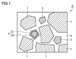
- FIG. 1 is a schematic view schematically showing one cross section of the cemented carbide according to the present embodiment.
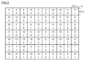
- FIG. 2 shows the number of second hard phase particles (upper) in which the particle size of the core portion existing in each unit region provided in the electron microscope image is 0.2 ⁇ m or more and 3 ⁇ m or less, and the particle size is 0.5 ⁇ m or more 2 It is a figure which showed the number (lower) of the 3rd hard phase particles of .5 ⁇ m or less.
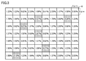
- FIG. 3 shows the second hard phase particles and the third hard phase particles existing in each unit region with respect to the total number of the second hard phase particles and the third hard phase particles existing in a total of 70 unit regions provided in the electron microscope image. It is explanatory drawing which showed the total number of particles as a percentage.
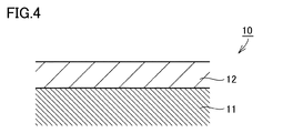
- FIG. 4 is a partial cross-sectional view showing an example of the configuration of the cutting tool according to the present embodiment.
- the composite carbonitride has a core represented by (Ti 1-xy L x Mo y ) (C 1-z N z).
- L is at least one element selected from the group consisting of Zr, Hf, Nb and Ta
- x is 0.01 or more and 0.5 or less
- y is 0.03 or more and 0.05 or less
- z is 0.05 or more and 0.75 or less. Therefore, the composite carbonitride has an atomic ratio of Mo to all metal elements (Ti, L, Mo) of 0.03 or more.
- welding resistance since Mo deteriorates the steel reactivity of the carbonitride itself (hereinafter, also referred to as "welding resistance”), its content is preferably small.
- Patent Document 2 regarding the second hard phase containing a composite carbide nitride containing Ti and W as a main component, the distance between the centers of gravity ( ⁇ 2 ) of the two particles in close contact with each other is reduced to obtain the second hard phase. It is disclosed that the cemented carbide is uniformly dispersed throughout the cemented carbide, thereby improving the fracture resistance. However, Patent Document 2 does not mention the steel reactivity of cemented carbide. For this reason, a hard material having excellent steel reactivity has not yet been obtained, and its development is eagerly desired.
- the cemented carbide of the present disclosure is A cemented carbide comprising a first hard phase particle, a second hard phase particle, a third hard phase particle, and a metal bonding phase.
- the first hard phase particles contain tungsten carbide and
- the second hard phase particle has a granular core portion and a peripheral portion that covers at least a part of the core portion.
- the core is made of the first composite carbonitride represented by Ti 1-XZ Nb X M Z C 1-Y NY.
- the peripheral portion is composed of a second composite carbonitride which is different in composition from the core portion and is a carbonitride containing at least titanium, niobium and tungsten.
- the M represents at least one element selected from the group consisting of vanadium, chromium and molybdenum.
- the X is 0.1 or more and 0.2 or less.
- the Y is 0.3 or more and 0.6 or less.
- the Z is 0 or more and 0.02 or less.
- the third hard phase particles consist of the first composite carbonitride.
- the metal bonding phase contains an iron group element and contains an iron group element.
- the cemented carbide has a total of 70 unit regions.
- the total of 70 unit regions are 7 unit regions in the vertical direction consisting of squares having a side of 8 ⁇ m in an electron microscope image obtained by photographing an arbitrary cross section of the cemented carbide at a magnification of 1500 times.
- the number of the unit regions having a percentage of less than 0.43% or more than 2.43% is 10 or less.
- the percentage is the inside of the unit region with respect to the total number of the second hard phase particles and the number of the third hard phase particles existing inside the total of 70 units in each unit region. It is a percentage of the total number of the number of the second hard phase particles and the number of the third hard phase particles existing in the above.
- the number of the second hard phase particles existing inside the unit region is the number of the second hard phase particles having a particle size of 0.2 ⁇ m or more and 3 ⁇ m or less in the core portion existing inside the unit region.
- the number of the third hard phase particles existing inside the unit region is the number of the third hard phase particles having a particle size of 0.5 ⁇ m or more and 2.5 ⁇ m or less inside the unit region.
- the cemented carbide has a core particle size of 0.2 ⁇ m or more and 3 ⁇ m or less in a total of 10 unit regions existing in the fourth row in the vertical direction out of a total of 70 unit regions.
- the third hard phase having a particle size of 0.5 ⁇ m or more and 2.5 ⁇ m or less with respect to the total number of hard phase particles and the total number of the third hard phase particles having a particle size of 0.5 ⁇ m or more and 2.5 ⁇ m or less.
- a cemented carbide in which the percentage of the number of particles is 5% or more and 15% or less.
- the cemented carbide of the present disclosure can have excellent fracture resistance and excellent steel reactivity.
- the average thickness of the peripheral portion is preferably 10 nm or more and 100 nm or less. According to this, the decrease in the interfacial strength between the second hard phase particles and the metal bonding phase is suppressed, and the mechanical properties of the cemented carbide are improved.
- the average particle size of the core portion is preferably 0.2 ⁇ m or more and 2 ⁇ m or less. According to this, the steel reactivity of the cemented carbide is further improved.
- the average particle size of the third hard phase particles is preferably 0.5 ⁇ m or more and 2.5 ⁇ m or less. According to this, the steel reactivity of the cemented carbide is further improved.
- the cemented carbide preferably contains the second hard phase particles in an amount of 2% by volume or more and 10% by volume or less. According to this, the steel reactivity of the cemented carbide is further improved.
- the cemented carbide preferably contains the third hard phase particles in an amount of 3% by volume or more and 20% by volume or less. According to this, the steel reactivity of the cemented carbide is further improved.
- the cutting tool of the present disclosure includes the above cemented carbide.
- Such a cutting tool can have excellent steel reactivity in addition to the excellent mechanical strength inherent in cemented carbide.
- the cutting tool preferably includes a base material made of the cemented carbide and a coating film covering the base material. Such a cutting tool can also have excellent steel reactivity in addition to the excellent mechanical strength inherent in cemented carbide.
- the notation in the form of "A to B” means the upper and lower limits of the range (that is, A or more and B or less), and when there is no description of the unit in A and the unit is described only in B, A The unit of and the unit of B are the same.
- the atomic ratio when a compound or the like is represented by a chemical formula, when the atomic ratio is not particularly limited, it shall include all conventionally known atomic ratios, and is not necessarily limited to those in the stoichiometric range.
- metallic elements such as titanium (Ti), chromium (Cr), niobium (Nb), tungsten (W), vanadium (V), and non-metallic elements such as nitrogen (N) or carbon (C) are used. Does not necessarily constitute a chemical quantitative composition.
- mechanical strength means mechanical strength including various properties such as wear resistance, fracture resistance and flexural strength of cemented carbide.
- TiNbMCN carbonitride containing Ti and Nb
- M represents at least one element selected from the group consisting of vanadium, chromium and molybdenum.
- WC tungsten carbide
- TiNbMCN tends to aggregate in cemented carbide.
- TiNbMCN tends to dissolve in WC crystals in the sintering process for producing cemented carbide. bottom.
- the cemented carbide 5 As shown in FIG. 1, the cemented carbide 5 according to one embodiment of the present disclosure (hereinafter, also referred to as “the present embodiment”) is A cemented carbide comprising a first hard phase particle 1, a second hard phase particle 2, a third hard phase particle 3, and a metal bonding phase 4.
- the first hard phase particle 1 contains tungsten carbide and contains
- the second hard phase particle 2 has a granular core portion 21 and a peripheral portion 22 that covers at least a part of the core portion 21.
- the core portion 21 is made of a first composite carbonitride represented by Ti 1-XZ Nb X M Z C 1-Y NY.
- the peripheral portion 22 is composed of a second composite carbonitride which is different in composition from the core portion and is a carbonitride containing at least titanium, niobium and tungsten.
- the M represents at least one element selected from the group consisting of vanadium, chromium and molybdenum.
- the X is 0.1 or more and 0.2 or less.
- the Y is 0.3 or more and 0.6 or less.
- the Z is 0 or more and 0.02 or less.
- the third hard phase particle 3 is made of the first composite carbonitride.
- the metal bonding phase 4 contains an iron group element and contains an iron group element.
- the cemented carbide 5 has a total of 70 unit regions R.
- the total of 70 unit regions R are formed by vertically forming the unit region R composed of a square having a side of 8 ⁇ m in an electron microscope image obtained by photographing an arbitrary cross section of the cemented carbide 5 at a magnification of 1500 times. It is provided by arranging 7 pieces in a row and 10 pieces in the horizontal direction. Of the total of 70 unit regions R, the number of the unit regions R having a percentage of less than 0.43% or more than 2.43% is 10 or less. The percentage is based on the total number of the second hard phase particles 2 and the number of the third hard phase particles 3 existing inside the 70 unit regions R in each unit region R.
- the number of the second hard phase particles 2 existing inside the unit region R is the number of the second hard phase particles 2 having a particle size of 0.2 ⁇ m or more and 3 ⁇ m or less in the core portion existing inside the unit region R. can be,
- the number of the third hard phase particles 3 existing inside the unit region R is the number of the third hard phase particles 3 having a particle size of 0.5 ⁇ m or more and 2.5 ⁇ m or less inside the unit region R.
- the particle size of the core portion 21 is 0.2 ⁇ m or more and 3 ⁇ m or less in the total of 10 unit regions R existing in the fourth row in the vertical direction out of the total of 70 unit regions R.
- the particle size is 0.5 ⁇ m or more and 2.5 ⁇ m or less with respect to the total number of the second hard phase particles 2 and the total number of the third hard phase particles 3 having a particle size of 0.5 ⁇ m or more and 2.5 ⁇ m or less.
- the cemented carbide 5 has a percentage of the number of the third hard phase particles 3 of 5% or more and 15% or less. Cemented carbide having such characteristics can have excellent fracture resistance and excellent steel reactivity.
- the first hard phase particle 1 contains tungsten carbide (WC).
- the main component of the first hard phase particle 1 is WC (tungsten carbide).
- the first hard phase particles 1 can contain unavoidable elements mixed in the manufacturing process of WC, trace amounts of impurity elements, and the like.
- the content of WC in the first hard phase particles 1 is preferably 99% by mass or more, more preferably 100% by mass, from the viewpoint of achieving the effects of the present disclosure.
- elements other than W and C that can be contained in the first hard phase particle 1 include molybdenum (Mo) and chromium (Cr).
- the volume ratio of the first hard phase particles 1 is preferably 65 to 95% by volume.
- the volume ratio of the first hard phase particles 1 in the cemented carbide is 65% by volume or more, the mechanical strength is improved.
- the volume ratio of the first hard phase particles 1 in the cemented carbide is 95% by volume or less, the toughness is improved.
- the preferable volume ratio of the first hard phase particles 1 in the cemented carbide is 75 to 85% by volume.
- the volume ratio (volume%) of the first hard phase particles 1 in the cemented carbide 5 can be obtained by using the following measuring method.
- a sample having a smooth cross section is obtained by CP (Cross Section Policeher) processing of a cemented carbide using an argon beam or the like.
- CP Cross Section Policeher
- An electron microscope image (SEM-BSE image) of the cross section of the sample is obtained, and the outer edge of the first hard phase particle 1 in the electron microscope image is specified.
- the first hard phase particles 1 in the electron microscope image with respect to the total area of the cross section. Calculate the area ratio (area%) of the sum (total area) of the areas of all the particles.
- the threshold value is set so that only the pixels corresponding to the first hard phase particles that can be discriminated by the electron microscope image are white, and the pixels having a value less than the threshold value are set to black.
- "Otsu's discriminant analysis method” which is one of the well-known automatic threshold determination methods, is applied to the threshold setting conditions. Specific methods of "Otsu's discriminant analysis method” include Shigehiko Tanaka et al., "Otsu's discriminant analysis method using concentration co-occurrence histogram", “Image recognition / understanding symposium (MIRU2011)", Japan, image recognition. -As described in the Understanding Symposium (MIRU), July 2011, IS1-3: 93-96.
- the area ratio (area%) of the sum (total area) of the areas of all the particles of the first hard phase particles 1 in the electron microscope image to the total area of the cross section is the area ratio (area%) of the first hard phase particles 1 in the super hard alloy. It is considered to correspond to the volume ratio (volume%).
- Five electron microscope images (five fields of view) were prepared so that overlapping imaging portions did not appear in the cross section of the sample, and the volume ratio (volume%) of the first hard phase particles 1 was set in each of the five fields of view. calculate.
- the average value of the volume ratio (volume%) of the first hard phase particles 1 in the five fields is taken as the volume ratio (volume%) of the first hard phase particles 1 in the cemented carbide in the present embodiment.
- the threshold value was about 170.
- the threshold value is a reference value because it is a value that is affected by the contrast of the image and the like. It has been confirmed that even if a value of around 170 is adopted as the threshold value, there is almost no effect on the measurement result.
- the volume ratio (volume%) of the first hard phase particles may be measured a plurality of times by changing the selection point of the measurement field as long as the measurement is performed on the same sample. It was confirmed that there was almost no variation in the measurement results, and that even if the measurement field was set arbitrarily, it would not be arbitrary.
- the second hard phase particle 2 includes a granular core portion 21 and a peripheral portion 22 that covers at least a part of the core portion 21.
- the volume ratio of the second hard phase particles 2 is preferably 2% by volume or more and 10% by volume or less.
- the volume ratio of the second hard phase particles 2 in the cemented carbide is 2% by volume or more, the steel reactivity is improved.
- the volume ratio of the second hard phase particles 2 in the cemented carbide is 10% by volume or less, the mechanical strength is improved.
- the lower limit of the volume ratio of the second hard phase particles 2 in the cemented carbide can be 2% by volume or more, 4% by volume or more, and 5% by volume or more.
- the upper limit of the volume ratio of the second hard phase particles 2 in the cemented carbide can be 10% by volume or less and 7% by volume or less.
- the volume ratio (volume%) of the second hard phase particles in the cemented carbide is determined by specifying the second hard phase particles instead of the first hard phase particles in the method for measuring the volume ratio of the first hard phase particles. Can be sought. Since the specific measuring method is the same as the measuring method of the volume ratio of the first hard phase particles, the description thereof will not be repeated.
- the core portion 21 is made of the first composite carbon nitride represented by Ti 1-XZ Nb X M Z C 1-Y NY , and the above M is made of vanadium (V), chromium (Cr) and molybdenum (Mo). Indicates at least one element selected from the group, X is 0.1 or more and 0.2 or less, Y is 0.3 or more and 0.6 or less, and Z is 0 or more. It is 0.02 or less.
- the cemented carbide has excellent fracture resistance and excellent steel resistance when the composition (Ti, Nb, C and N) of the granular core portion 21 in the second hard phase particles 2 has an atomic ratio in the above-mentioned range. It can be reactive.
- the core portion 21 contains Ti as a main component and Nb as a sub component.
- the above M is at least one element selected from the group consisting of V, Cr and Mo.
- the atomic ratio of Ti (1-XZ) is 0.8 or more and 0.9 or more from the viewpoint of keeping the amount of the sub-component added below the solid solution limit and sufficiently drawing out the effects of the added metal elements Ti and Nb. It is as follows.
- Y which represents the atomic ratio of nitrogen (N) in the first composite carbonitride, is 0.3 or more and 0.6 or less from the viewpoint of obtaining excellent steel reactivity resistance.
- the composition of the core portion 21 should be particularly limited as long as it exhibits the effects of the present disclosure, has an atomic ratio (X, Y, Z) in the above range, and is different in composition from the peripheral portion 22.
- X, Y, Z atomic ratio
- Ti 0.85 Nb 0.15 C 0.5 N 0.5 , Ti 0.8 Nb 0.2 C 0.45 N 0.55 and the like can be mentioned.
- X is preferably 0.12 or more and 0.18 or less. Further, X is more preferably 0.14 or more and 0.16 or less. Y is preferably 0.4 or more and 0.55 or less. As a result, it is possible to obtain excellent steel reactivity and also favorable characteristics in terms of mechanical strength such as wear resistance and fracture resistance.
- M is at least one element selected from the group consisting of V, Cr and Mo. Therefore, the core 21 may contain at least one element selected from the group consisting of V, Cr and Mo.
- Z is 0 or more and 0.02 or less, that is, the total amount of V, Cr and Mo in the total amount of Ti, Nb, V, Cr and Mo is less than 2 atomic%.
- the composition of the first composite carbonitride contained in the core portion 21 and its atomic ratio can be determined by using the following measuring method.
- An electron microscope image (SEM-BSE image) of the cross section of the sample is obtained by the same method as in the case of determining the volume ratio of the first hard phase particles.
- an energy dispersive X-ray spectroscope (EDX) in which the core portion 21 contained in the second hard phase particles 2 appearing therein is attached to the above-mentioned electro-emission scanning electron microscope (FE-SEM).
- FE-SEM electro-emission scanning electron microscope
- it can be identified by analysis using an electron microscope microanalyzer (EPMA).
- composition of the first hard phase particles, the composition of the peripheral portion of the second hard phase particles described later, the composition of the third hard phase particles, and the composition of the iron group element in the metal bonding phase are also the first hard appearing in the electron microscope image.
- these compositions can be identified by the same measuring method.
- the core portion preferably has an average particle size of 0.2 ⁇ m or more and 2 ⁇ m or less. As a result, the steel reactivity of the cemented carbide is further improved.
- the average particle size of the core portion is more preferably 0.6 ⁇ m or more and 1.6 ⁇ m or less, and further preferably 0.8 ⁇ m or more and 1.4 ⁇ m or less. When the average particle size of the core portion is 0.2 ⁇ m or more, the steel reactivity is further improved. When the average particle size of the core portion is 2 ⁇ m or less, the mechanical strength is improved.
- the particle size of each core can be obtained by using the following method.
- An electron microscope image (SEM-BSE image) of the cross section of the sample is obtained by the same method as in the case of determining the volume ratio of the first hard phase particles.
- the core portion is specified by binarizing the electron microscope image using the image analysis software used in the measurement of the volume ratio of the first hard phase particles.
- a threshold value is set so that only the pixels corresponding to the core portion that can be visually identified by the electron microscope image are white, and the pixels having a value less than the threshold value are set to black.
- the diameter of a circle having an area equal to the area of the core portion (circle equivalent diameter) is calculated, and this circle equivalent diameter is defined as the particle size of the core portion.
- the circle-equivalent diameters of all the core portions appearing in the electron microscope image are calculated, and the average value of the calculated circle-equivalent diameters is used.
- the core portion is visually discriminated on the electron microscope image. It has been confirmed that the same result can be obtained when the core portion is visually discriminated on the same electron microscope image by a plurality of observers. Therefore, even if the core portion is visually discriminated on the electron microscope image, the result does not vary depending on the observer.
- the threshold value was about 65.
- the threshold value is a reference value because it is a value that is affected by the contrast of the image and the like. It has been confirmed that even if a value of around 65 is adopted as the threshold value, there is almost no effect on the measurement result.
- the average particle size of the core is measured a plurality of times by changing the selection point of the measurement field of view, the measurement result varies. It was confirmed that there was almost no measurement, and even if the measurement field of view was set arbitrarily, it was not arbitrary.
- the "particle size” means a "circle equivalent diameter” measured by the same method as described above.
- the second hard phase particle 2 includes a peripheral portion 22 that covers at least a part of the core portion 21.
- the peripheral portion has a composition different from that of the core portion 21, and is composed of a second composite carbonitride which is a carbonitride containing at least titanium, niobium, and tungsten.
- the peripheral portion 22 is formed in a cemented carbide sintering step (fourth step) described later.
- the particles made of the first composite carbonitride and the surrounding WC particles are mutually solid-solved and dissolved and redisposited during liquid phase sintering, so that the first composite carbonitride (Ti 1) of the core portion 21 is formed.
- -XZ Nb X M Z C 1-Y NY is formed around the core 21 as a composition richer in W and C than the composition. Therefore, the peripheral portion 22 covers at least a part of the core portion 21, and the composition of the peripheral portion 22 is different from that of the core portion 21.
- the peripheral portion 22 functions as an adhesion layer that enhances the adhesion strength between the second hard phase particles 2 and the metal bonding phase 4. As a result, it is possible to suppress a decrease in the interfacial strength between the second hard phase particles 2 and the metal bonding phase 4, and thus it is possible to improve the mechanical properties of the cemented carbide.
- the peripheral portion 22 may partially or completely cover the core portion 21 as long as the effects of the present disclosure are exhibited.
- the composition of the peripheral portion 22 should not be particularly limited as long as the composition of the peripheral portion 22 is effective and the composition is different from that of the core portion 21, but for example, Ti 1-ac Nb a W c C 1-b N b ( A is 0.05 or more and 0.15 or less, b is 0.2 or more and 0.5 or less, and c is 0 or more and 5 or less.)
- the average thickness of the peripheral portion 22 is preferably 10 nm or more and 100 nm or less. According to this, the decrease in the interfacial strength between the second hard phase particles and the metal bonding phase is suppressed, and the mechanical properties of the cemented carbide are improved.
- the lower limit of the average thickness of the peripheral portion is preferably 15 nm or more, more preferably 20 nm or more, and further preferably 30 nm or more.
- the upper limit of the average thickness of the peripheral portion is preferably 90 nm or less, more preferably 80 nm or less, and further preferably 70 nm or less.
- the thickness of each peripheral part can be measured by using the following method.
- An electron microscope image (SEM-BSE image) of the cross section of the sample is obtained by the same method as in the case of determining the volume ratio of the first hard phase particles.
- the thickness of any three points was measured in each peripheral part, and the average value of these was measured in each peripheral part.
- the thickness If each peripheral portion does not cover the entire core portion, the thickness of the peripheral portion at any three locations is measured in the area where the peripheral portion exists, and the average value of these is measured for each peripheral portion.
- the thickness Regarding the average thickness of the peripheral portion, the thickness of all the peripheral portions appearing in the electron microscope image is calculated, and the average value of the calculated thickness is used.
- the third hard phase particles consist of the first composite carbonitride represented by Ti 1-XZ Nb X M Z C 1-Y NY. That is, the composition of the third hard phase particles is shown by the same composition formula as the core portion of the second hard phase particles, and the ranges of X, Y, and Z can be the same, so the description thereof will not be repeated.
- the values of X, Y, and Z may be the same or different in the core portion of the third hard phase particle and the second hard phase particle as long as they are within the above ranges.
- the volume ratio of the third hard phase particles 3 is preferably 3% by volume or more and 20% by volume or less.
- the content of the second hard phase particles 2 in the cemented carbide is 3% by volume or more, the steel reactivity is improved.
- the content of the third hard phase particles 3 in the cemented carbide is 20% by volume or less, the mechanical strength is improved.
- the preferable content of the third hard phase particles 3 in the cemented carbide is 5% by volume or more and 15% by volume or less.
- the volume ratio (volume%) of the third hard phase particles can be obtained by specifying the third hard phase particles instead of the first hard phase particles in the method of measuring the volume ratio of the first hard phase particles. .. Since the specific measuring method is the same as the measuring method of the volume ratio of the first hard phase particles, the description thereof will not be repeated.
- the average particle size of the third hard phase particles 3 is preferably 0.5 ⁇ m or more and 2.5 ⁇ m or less. As a result, the steel reactivity of the cemented carbide is further improved.
- the average particle size of the third hard phase particles 3 is more preferably 0.8 ⁇ m or more and 2.3 ⁇ m or less, and further preferably 1.0 ⁇ m or more and 2.0 ⁇ m or less. When the average particle size of the third hard phase particles 3 is 1.2 ⁇ m or more, the steel reactivity is further improved. When the average particle size of the third hard phase particles 3 is 1.5 ⁇ m or less, the mechanical strength is further improved.
- the average particle size of the third hard phase particles is determined by specifying the third hard phase particles instead of the core in the method for measuring the average particle size of the second hard phase particles, calculating the equivalent circle diameter thereof, and based on this. Obtained by determining the average particle size. Since the specific measuring method is the same as the measuring method of the average particle size of the second hard phase particles, the description thereof will not be repeated.
- the metal bonding phase 4 contains an iron group element. That is, the main component of the metal bonding phase 4 is an iron group element. In addition to the iron group elements, the metal bonding phase 4 can contain unavoidable elements mixed from the first hard phase particles 1, the second hard phase particles 2, and the third hard phase particles 3, a trace amount of impurity elements, and the like.
- the content of the iron group element in the metal bonding phase 4 is preferably 90 atomic% or more, more preferably 95 atomic% or more, from the viewpoint of maintaining the metal state and avoiding the formation of a brittle intermediate compound.
- the upper limit of the content of iron group elements in the metal bonding phase 4 is 100 atomic%.
- the iron group elements refer to the elements of Group 8, Group 9, and Group 10 of the 4th period, that is, iron (Fe), cobalt (Co), and nickel (Ni).
- the element other than the iron group element contained in the metal bonding phase 4 include titanium (Ti) and tungsten (W).
- the main component of the metal bonding phase 4 is preferably Co.
- the content of iron group elements other than Co in the metal bonding phase 4 is preferably less than 1% by volume, more preferably less than 0.5% by volume.
- the content of the metal bonding phase 4 is preferably 7 to 15% by volume.
- the content of the metal bonding phase 4 in the cemented carbide is 7% by volume or more, sufficient adhesion strength is obtained and toughness is improved.
- the content of the metal bonding phase 4 in the cemented carbide is 15% by volume or less, the hardness is improved.
- a more preferable content of the metal bonding phase 4 in the cemented carbide is 9 to 13% by volume.
- the content (% by volume) of the metal bonding phase 4 can be determined by the same method as the method for measuring the content of the first hard phase particles 1.
- the total content of the first hard phase particles 1, the second hard phase particles 2 and the metal bonding phase 4 is preferably 95% by volume or more, more preferably 98% by volume or more, and 100 volumes. Most preferably. As a result, excellent steel reactivity can be provided with a good yield.
- the cemented carbide 5 has a total of 70 unit regions R.
- the total of 70 unit regions R are formed by vertically forming the unit region R composed of a square having a side of 8 ⁇ m in an electron microscope image obtained by photographing an arbitrary cross section of the cemented carbide 5 at a magnification of 1500 times. It is provided by arranging 7 pieces in a row and 10 pieces in the horizontal direction.
- the number of the unit regions R having a percentage of less than 0.43% or more than 2.43% is 10 or less.
- the percentage is based on the total number of the second hard phase particles 2 and the number of the third hard phase particles 3 existing inside the 70 unit regions R in each unit region R. It is a percentage of the total number of the number of the second hard phase particles 2 and the number of the third hard phase particles 3 existing inside the unit region R.
- the number of the second hard phase particles 2 existing inside the unit region R is the number of the second hard phase particles 2 having a particle size of 0.2 ⁇ m or more and 3 ⁇ m or less in the core portion existing inside the unit region R. can be,
- the number of the third hard phase particles 3 existing inside the unit region R is the number of the third hard phase particles 3 having a particle size of 0.5 ⁇ m or more and 2.5 ⁇ m or less inside the unit region R. ..
- the second hard phase particles and the third hard phase particles are biased in the cemented carbide. It can be judged that the particles are uniformly dispersed.
- the present inventors have found that cemented carbide has excellent steel reactivity resistance in this case. Furthermore, it has also been found that when the number of the unit regions is 11 or more, it becomes difficult for the cemented carbide to have the desired excellent steel reactivity resistance.
- whether or not the core portion is uniformly and uniformly dispersed in the cemented carbide may be explained by using the term "dispersity of the core portion" in the cemented carbide and by its height. be.
- each unit region R is provided by arranging 7 unit regions R in the vertical direction and 10 unit regions R in the horizontal direction in the electron microscope image.
- the size of each unit region R shall be a square with a side of 8 ⁇ m.
- the particle size of the core inside each unit region R is 0.2 ⁇ m or more and 3 ⁇ m or less.
- the number of hard phase particles and the number of third hard phase particles having a particle size of 0.5 ⁇ m or more and 2.5 ⁇ m or less are counted.
- the number of the second hard phase particles is shown in the upper row in each unit region R
- the number of the third hard phase particles is shown in the lower row in each unit region R.
- the second hard phase particles and the third hard phase particles can be distinguished from each other by the difference in contrast of the composition image. If it is only black particles, it is a third hard phase particle, and if there is a gray part around the black particles, it is a second hard phase particle.
- the first hard phase particles are white.
- the particle size of the core portion means the diameter of a circle having an area equal to the area of the core portion (circle equivalent diameter). Since the method for calculating the particle size of the core portion is the same as the method used for calculating the particle size of the core portion, the description thereof will not be repeated.
- the particle size of the third hard phase particles means the diameter of a circle having an area equal to the area of the third hard phase particles (circle equivalent diameter). Since the method for calculating the particle size of the third hard phase particles is the same as the method used for calculating the particle size of the third hard phase particles, the description thereof will not be repeated.
- the total number of the core portion and the third hard phase particles existing inside the total 70 unit regions R is obtained, and as shown in FIG. 3, they are inside each unit region R with respect to the total number.
- the percentage of the total number of the second hard phase particles and the third hard phase particles is calculated.
- the second hard phase particles and the third hard phase particles are contained in the cemented carbide.
- the total number of the second hard phase particles and the third hard phase particles represented by the above percentages in each unit region R is 1.43% (1/70 ⁇ 100%). It becomes. Therefore, when the total number (percentage) of the second hard phase particles and the third hard phase particles counted in the unit region R is within 0.43% to plus or minus 1%, which is within 0.43 to 2.43%. , It is determined that there is no bias in the total number of the second hard phase particles and the third hard phase particles in the unit region R.
- the total number (percentage) of the second hard phase particles and the third hard phase particles counted in the unit region R is less than 0.43% or more than 2.43%, which is more than plus or minus 1% from 1.43%. In this case, it is determined that the total number of the second hard phase particles and the third hard phase particles is biased in the unit region R.
- the number of unit regions R in which the total number of the second hard phase particles and the third hard phase particles represented by the above percentage exceeds 0.43% or 2.43% is determined.
- the number of the unit regions R is also referred to as "dispersity of the second hard phase particles and the third hard phase particles").
- the number of unit regions R in which the total number of the second hard phase particles and the third hard phase particles exceeds 0.43% or 2.43% is 10 or less (15% or less of the total number of unit regions R). ) Since the degree of dispersion of the second hard phase particles and the third hard phase particles is high, excellent steel reactivity can be provided. From the above, by analyzing whether or not the number of unit regions R in which the percentage is less than 0.43% or exceeds 2.43% in the electron microscope image is 10 or less, the second in the cemented carbide. It is possible to evaluate the degree of dispersion of the hard phase particles and the third hard phase particles.
- the cemented carbide used in the electron microscope image can be evaluated as having a high degree of dispersion of the second hard phase particles and the third hard phase particles, and can be provided with excellent steel reactivity.
- the number of the second hard phase particles having a core particle size of 0.2 ⁇ m or more and 3 ⁇ m or less and the particle size are 0. .
- the core and the third hard phase particles (Ti 1-X Nb X C 1-Y N Y) which are not solid-solved in the crystals of tungsten carbide constituting the first hard phase particles are the first composite. This is because it targets only carbide).
- the second hard phase particles having a core particle size of less than 0.2 ⁇ m and the third hard phase particles having a particle size of less than 0.5 ⁇ m cause aggregation in the cemented carbide and are disadvantageous in steel reactivity. Tends to have an impact.
- the second hard phase particles having a core particle size of more than 3 ⁇ m and the third hard phase particles having a particle size of more than 2.5 ⁇ m are steel resistant due to difficulty in fine dispersion in the cemented carbide. It tends to have a negative effect on reactivity.
- the core portion of the second hard phase particles and the third hard phase particles were present in the adjacent unit region R.
- the second hard phase particles and the third hard phase particles are counted as being included in the unit region R having the smallest number among the unit regions R existing straddling the particles.
- five electron microscope images (five fields of view) are prepared so that overlapping imaging portions do not appear on one cross section of the cemented carbide.
- the five visual fields are preferably one visual field in the central portion of the one cross section and four visual fields located vertically and horizontally with respect to the one visual field.
- the number of unit regions R having a percentage of less than 0.43% or exceeding 2.43% in each of the five visual fields is determined, and the number of the unit regions R is 10 in three or more visual fields out of the five visual fields. Only in the following cases, it is determined that the number of unit regions having a percentage of less than 0.43% or more than 2.43% in the superhard alloy provided with the electron microscope image is 10 or less.
- the cemented carbide according to the present embodiment has a core particle size of 0.2 ⁇ m or more and 3 ⁇ m or less in a total of 10 unit regions existing in the fourth row in the vertical direction out of a total of 70 unit regions. Percentage of the number of third hard phase particles having a particle size of 0.5 ⁇ m or more and 2.5 ⁇ m or less with respect to the total number of the two hard phase particles and the third hard phase particles having a particle size of 0.5 ⁇ m or more and 2.5 ⁇ m or less. (Hereinafter, also referred to as “number percentage of third hard phase particles”) is 5% or more and 15% or less.
- the number percentage of the third hard phase particles is 5% or more and 15% or less, it can be determined that the second hard phase particles having a peripheral portion are sufficiently present in the cemented carbide.
- the present inventors have found that cemented carbide has excellent fracture resistance in this case. Furthermore, it was also found that when the number percentage of the third hard phase particles is less than 5%, sufficient steel reactivity cannot be exhibited, and when it exceeds 15%, sufficient fracture resistance cannot be exhibited.
- number percentage measuring method a method for evaluating the number percentage of the third hard phase particles in the present embodiment (hereinafter, also referred to as “number percentage measuring method”) will be described with reference to FIGS. 2 and 3.
- the particle size of the core portion is A second hard phase particle having a particle size of 0.5 ⁇ m or more and 2.5 ⁇ m or less with respect to the total number of second hard phase particles of 0.2 ⁇ m or more and 3 ⁇ m or less and a third hard phase particle having a particle size of 0.5 ⁇ m or more and 2.5 ⁇ m or less. 3 Calculate the ratio of the number of hard phase particles.
- the total number of the second hard phase particles and the third hard phase particles is 97 in the total of 10 unit regions, and the number of the third hard phase particles is 10. Therefore, the number percentage of the third hard phase particles is 10.3%. Therefore, it can be determined that the second hard phase particles having a peripheral portion are sufficiently present in the cemented carbide used in the electron microscope image, and the cemented carbide has excellent fracture resistance. Can be prepared.
- the number percentage measurement method is performed on an electron microscope image with five fields of view in the same manner as the dispersion measurement method. Only when the number percentage of the third hard phase particles is 5% or more and 15% or less in three or more fields of view in the five fields of view, in the cemented carbide provided with the electron microscope image, the number percentage of the third hard phase particles is It is judged that it is 5% or more and 15% or less.
- the cemented carbide according to the first embodiment can be produced by the following method.
- the method for producing cemented carbide includes a step of obtaining a powder of the first composite carbonitride represented by Ti 1-XZ Nb X M Z C 1-Y NY (first step) and the above-mentioned first composite carbide nitride.
- M is at least one impurity element selected from the group consisting of V, Cr and Mo, and X is 0.1 or more and 0. It is 2 or less, Y is 0.3 or more and 0.6 or less, and Z is 0 or more and 0.02 or less.
- the first step is a step of obtaining the powder of the first composite carbonitride represented by Ti 1-XZ Nb X M Z C 1-Y NY.
- the first step further includes each of the following steps. That is, in the step of obtaining the powder of the first composite carbide, which is the first step, the first powder containing Ti and Nb and the second powder containing at least graphite are mixed to obtain a third powder.
- the first powder contains Ti and Nb.
- the first powder is preferably an oxide containing Ti and Nb.
- the first powder is an oxide, it becomes easy to make the primary particle size of the powder of the first composite carbonitride obtained by the crushing step described later finer, and thus the average particle size is, for example, 0.2 to. It can be 2 ⁇ m.
- the first powder may contain one or more kinds of impurity elements selected from the group consisting of V, Cr and Mo as mixed components from equipment used for production and the like.
- the total amount of V, Cr and Mo in the first powder is preferably less than 2 atomic% with respect to the total amount of Ti, Nb, V, Cr and Mo.
- Specific examples of the first powder include composite oxides such as Ti 0.9 Nb 0.1 O 2.
- the first powder may be a mixed powder containing an oxide powder such as TiO 2 and Nb 2 O 5. The oxidation number of each element, the content of impurity elements, etc. can be changed as long as it does not defeat the purpose.
- the second powder contains at least graphite.
- the mixing step the second powder and the first powder are mixed to obtain a third powder.
- the reduction reaction of the oxide, the solidification reaction of the reduced oxide by mutual diffusion of Ti and Nb, and the carbonitriding reaction of the solidified Ti and Nb are simultaneously and continuously performed. Can be advanced. As a result, the composite carbonitride can be efficiently obtained.
- a mixing method for mixing the first powder and the second powder a conventionally known method can be used.
- a mixing method using a dry ball mill having a high crushing action and a mixing method using a wet ball mill can be preferably used.
- a mixing method using a rotary blade type flow mixer having a low crushing action can also be applied.
- the average particle size of the third powder can be determined based on all the particles of the third powder appearing in the observation image observed at a magnification of 10000 times using an SEM (scanning electron microscope).
- the equivalent circle diameter of the particles can be calculated using the above-mentioned image analysis software, and the average value thereof can be used as the average particle size of the third powder.
- the mixing ratio (volume ratio) of the first powder and the second powder is preferably 0.3 to 0.4 for the second powder when the first powder is 1.
- a granulated body is obtained by granulating the third powder.
- a conventionally known granulation method can be used.
- a method using a known device such as a spray dryer or an extruder granulator can be mentioned.
- a binder component such as a wax material can be appropriately used as a binder.
- the shape and dimensions of the granules should not be particularly limited.
- the granulated body can have, for example, a cylindrical shape having a diameter of 0.5 to 5 mm and a length of 5 to 20 mm.
- the granulated product is heat-treated in an atmosphere containing nitrogen gas at 1800 ° C. or higher to obtain a powder precursor composed of the first composite carbonitride.
- oxygen in the oxide in the first powder contained in the granulated body reacts with graphite in the second powder in an atmosphere containing nitrogen gas, and Ti and Nb in the first powder are reduced. Will be done.
- the reduced Ti and Nb undergo a mutual solution reaction by mutual diffusion.
- a carbon nitriding reaction occurs in which the reduced Ti and Nb react with nitrogen in the atmosphere and graphite in the second powder.
- a powder precursor composed of the first composite carbonitride represented by Ti 1-XZ Nb X M Z C 1-Y NY described above is formed.
- a metal powder containing Ti and Nb, or a mixed powder obtained by mixing a powder containing Ti carbonitride and Nb carbonitride with the second powder is used under the above-mentioned conditions. Even if the heat treatment is performed underneath, a powder precursor composed of the first composite carbonitride cannot be obtained. This is because the metal powder containing Ti and Nb undergoes the carbonitriding reaction at an early stage by the heat treatment, so that the solution reaction due to the mutual diffusion of Ti and Nb does not proceed. Further, since the powder containing the carbonitride of Ti and the carbonitride of Nb is chemically stable even in a high temperature region exceeding 2000 ° C., the solution reaction due to the mutual diffusion of Ti and Nb does not proceed. ..
- the atmosphere of the heat treatment in the heat treatment step should not be particularly limited as long as the atmosphere contains nitrogen gas. May be pure N 2 gas, the N 2 gas, hydrogen gas (H 2 gas), argon gas (Ar gas), helium gas (He gas), carbon monoxide gas (CO gas), etc. are mixed It may be a mixed gas.
- the temperature of the heat treatment in the heat treatment step is 1800 ° C. or higher, preferably 2000 ° C. or higher, from the viewpoint of advancing and promoting the reduction reaction, solution reaction and carbonitriding reaction of the first powder.
- the temperature is preferably 2400 ° C. or lower.
- the heat treatment time in the heat treatment step is preferably adjusted by the average particle size of the third powder.
- the heat treatment time is preferably 15 to 60 minutes. It is preferable that the smaller the value of the average particle size of the third powder, the shorter the heat treatment time in the heat treatment step, and the larger the value of the average particle size of the third powder, the longer the heat treatment time in the heat treatment step.
- a rotary continuous heat treatment device such as a rotary kiln.
- This heat treatment apparatus includes an inclined rotary reaction tube. Furthermore, a heating mechanism for heating the rotary reaction tube, a gas inlet for introducing nitrogen-containing gas into the rotary reaction tube, a gas discharge port for discharging nitrogen-containing gas from the rotary reaction tube, and a rotary reaction. It also has an inlet for putting the granules in the tube and an outlet for taking out the powder precursor from the rotary reaction tube.
- a heat treatment apparatus is preferable because the granulated body can be heat-treated under certain conditions, and thus a powder precursor of a composite carbonitride having stable quality can be continuously and efficiently produced.
- the rotary reaction tube is first heated to 1800 ° C. or higher by using a heating mechanism, and a gas containing nitrogen gas is introduced from the gas inlet to form the rotary reaction tube.
- the inside has a nitrogen atmosphere.
- the granulated body is continuously supplied from the inlet at the upper part of the rotary reaction tube, the rotary reaction tube is rotated, and the inside of the rotary reaction tube is moved to the granulated body to heat-treat the granulated body. do.
- This makes it possible to form a powder precursor composed of the first composite carbonitride powder. This powder precursor can be taken out from the outlet at the bottom of the rotary reaction tube.
- the powder of the first composite carbonitride is obtained by crushing the powder precursor obtained above.
- a conventionally known crushing method can be used.
- the powder of the composite carbonitride represented by Ti 1-XZ Nb X M Z C 1-Y NY can be obtained.
- M is at least one impurity element selected from the group consisting of V, Cr and Mo, and X is 0.1 or more and 0. It is 2 or less, Y is 0.3 or more and 0.6 or less, and Z is 0 or more and 0.02 or less.
- the second step is a step of obtaining a mixed powder by mixing the powder of the first composite carbonitride, the WC powder, and the powder of an iron group element with a ball mill for more than 15 hours and for 20 hours or less.
- a conventionally known mixing method using a ball mill can be used.
- the mixing time using this ball mill shall be more than 15 hours and 20 hours or less.
- the mixing time using a ball mill is preferably 16 hours or more and 18 hours or less.
- the mixing time using a ball mill is 15 hours or less, the dispersity of the first composite carbonitride (core) is sufficient in the cemented carbide produced through the sintering step (fourth step) due to insufficient mixing. There is a risk that it will not rise. If the mixing time using a ball mill exceeds 20 hours, there is a risk that the desired mechanical strength, especially the desired toughness, cannot be obtained in the cemented carbide produced through the sintering step (fourth step) due to excessive mixing. be.
- the third step is a step of obtaining a molded product by pressure molding the above-mentioned mixed powder.
- a conventionally known pressure molding method can be used.
- the mixed powder can be filled in a mold and molded into a predetermined shape at a predetermined pressure.
- the molding method include a dry pressure molding method, a cold hydrostatic pressure molding method, an injection molding method, and an extrusion molding method.
- the pressure at the time of molding is preferably about 0.5 ton weight / cm 2 (about 50 MPa) or more and 2.0 ton weight / cm 2 (about 200 MPa) or less.
- the shape of the molded product may be adjusted to the shape of the desired product, and a shape that does not become an excessively complicated shape is selected.
- the fourth step is a step of obtaining a sintered body by sintering the above-mentioned molded body.
- the sintering method for sintering the molded product is preferably performed by holding the molded product for a predetermined time in a temperature range where a liquid phase is generated.
- the sintering temperature is preferably 1350 ° C. or higher and 1500 ° C. or lower.
- the holding time is preferably 0.2 hours or more and less than 0.5 hours, and more preferably 0.3 hours or more and 0.4 hours or less.
- the atmosphere at the time of sintering is preferably an inert gas atmosphere such as nitrogen or argon or a vacuum (about 0.5 Pa or less).
- the composition of the composite carbonitride powder and its atomic ratio can be obtained by a conventionally known component analysis technique. For example, by using inductively coupled plasma emission spectroscopy, high frequency combustion method, and thermal conductivity method, the composition (metal, carbon, nitrogen, etc.) and its content in each powder can be identified.
- the average particle size of the composite carbonitride powder is controlled to 0.5 ⁇ m or more and 3.5 ⁇ m or less from the viewpoint of ease of handling and good steel reactivity when applied as a cutting tool described later. It is preferable to do so.
- the average particle size of the composite carbonitride powder can be determined by the same method as the method for measuring the average particle size of the third powder.
- the cutting tool according to the present embodiment includes the cemented carbide of the first embodiment. Since the cutting tool of the present embodiment contains the cemented carbide of the first embodiment, it can have excellent steel reactivity in addition to the excellent mechanical strength originally possessed by the cemented carbide.
- the above cutting tools include drills, end mills, replaceable cutting tips for drills, replaceable cutting tips for end mills, throwaway tips for milling, throwaway tips for turning, metal saws, gear cutting tools, reamers, taps, and cutting tools. , Applicable to wear-resistant tools, friction-stirring joining tools, etc.
- the base material may or may not have a tip breaker.
- the ridgeline of the cutting edge which is the center of cutting when cutting the work material, has a sharp edge (the ridge where the rake face and the flank face intersect) and honing (the sharp edge is rounded). ), Negative land (chamfered), and a combination of honing and negative land.
- the cutting tool according to the present embodiment includes a base material made of the cemented carbide of the first embodiment and a coating film covering the base material.
- FIG. 4 is a partial cross-sectional view showing an example of the configuration of the cutting tool 10 according to the present embodiment. As shown in FIG. 4, the cutting tool 10 includes a base material 11 made of the cemented carbide of the first embodiment and a coating film 12 that is in contact with the base material 11 and covers the base material 11. The cutting tool 10 is more excellent in wear resistance and fracture resistance because it further contains a coating film 12 in addition to the excellent mechanical strength and excellent steel reactivity inherent in cemented carbide.
- the coating film 12 may be coated on the entire surface of the base material 11, or may be coated only on a part (for example, a cutting edge which is a region that greatly contributes to cutting performance).
- the composition of the coating film 12 that coats the base material 11 is not particularly limited, and a conventionally known coating film 12 can be arbitrarily adopted.
- the composition of the coating film 12 that coats the base material 11 includes AlTiSiN, AlCrN, TiZrSiN, CrTaN, HfWSiN, CrAlN, TiN, TiBNO, TiCN, TiCNO, TiB 2 , TiAlN, TiAlCN, TiAlON, TiAlONC, Al 2 O 3 and the like. Can be exemplified.
- a conventionally known method can be used as a method of coating a base material made of cemented carbide with a coating.
- a conventionally known method can be used.
- it can be coated by a physical vapor deposition (PVD) method, a chemical vapor deposition (CVD) method, or the like.
- PVD physical vapor deposition
- CVD chemical vapor deposition
- a resistance heating vapor deposition method for example, a resistance heating vapor deposition method, an electron beam (EB) vapor deposition method, a molecular beam growth (MBE) method, an ion plating method, an ion beam deposition method, a sputtering method and the like can be used.
- EB electron beam
- MBE molecular beam growth
- Example 1 >> ⁇ Preparation of Samples 1 to 7>
- First step As the first powder, TiO 2 powder (size about 0.5 ⁇ m, manufactured by High Purity Chemical Laboratory Co., Ltd.) and Nb 2 O 5 powder (size about 1 ⁇ m, manufactured by High Purity Chemical Laboratory Co., Ltd.) were prepared. Graphite powder (size: about 5 ⁇ m, manufactured by High Purity Chemical Laboratory Co., Ltd.) was prepared as the second powder. A third powder was obtained by mixing these at a blending ratio such that the composition was as shown in the "Composition of the first composite carbonitride" column of Table 2 (mixing step). Mixing was carried out by a ball mill method.
- the granulated material was heat-treated at 1800 ° C. in a nitrogen atmosphere using the rotary kiln described above to obtain a powder precursor composed of the first composite carbonitride (heat treatment step).
- the transit time for the granulated material to pass through the heating section in the rotary kiln was about 30 minutes.
- the powder precursor was dry-crushed using a known crusher (a rolling ball mill and a cemented carbide ball having a diameter of 4.5 mm as a crushing medium) to obtain "Composition of the first composite carbonitride" in Table 2.
- a powder of the first composite carbide nitride having the composition shown in the column was obtained (crushing step).
- the composition of the first composite carbonitride of each sample was measured by the method described above.
- compositions of the core portion, the peripheral portion and the third hard phase particles of the second hard phase particles were analyzed using EDX by the above-mentioned method.
- the composition of the core portion of the second hard phase particles and the composition of the third hard phase particles were consistent with the composition of the first composite carbonitride shown in Table 2.
- the composition of the peripheral portion of the second hard phase particles is shown in the “Composition of peripheral portion” column of Table 2. It was visually confirmed by an electron microscope image that the peripheral portion covered at least a part of the core portion.
- the obtained cutting tool was subjected to a fracture resistance test and a steel reactivity test under the following conditions.
- Step reactivity test Work material: SCM435 Peripheral speed: 100 m / min Feed: 0.15 mm / rev Notch: 1.5 mm Cutting oil: None.
- Samples 1 to 3 correspond to Examples.
- Samples 4 to 6 have a dispersity of more than 10, and correspond to a comparative example.
- Sample 7 corresponds to a comparative example because the dispersity is more than 10 and the number percentage of the third hard phase particles is less than 5%. It was confirmed that the cutting tools of Samples 1 to 3 (Example) were superior in fracture resistance and steel reactivity to the cutting tools of Samples 4 to 7 (Comparative Example).
Landscapes
- Chemical & Material Sciences (AREA)
- Engineering & Computer Science (AREA)
- Mechanical Engineering (AREA)
- Materials Engineering (AREA)
- Metallurgy (AREA)
- Organic Chemistry (AREA)
- Life Sciences & Earth Sciences (AREA)
- Forests & Forestry (AREA)
- Cutting Tools, Boring Holders, And Turrets (AREA)
- Powder Metallurgy (AREA)
Abstract
Description
第1硬質相粒子と、第2硬質相粒子と、第3硬質相粒子と、金属結合相と、を備える超硬合金であって、
前記第1硬質相粒子は、炭化タングステンを含み、
前記第2硬質相粒子は、粒状の芯部と、前記芯部の少なくとも一部を被覆する周辺部と、を有し、
前記芯部は、Ti1-X-ZNbXMZC1-YNYで示される第1複合炭窒化物からなり、
前記周辺部は、前記芯部と組成が異なり、少なくともチタン、ニオブおよびタングステンを含む炭窒化物である第2複合炭窒化物からなり、
前記Mは、バナジウム、クロムおよびモリブデンからなる群より選択される少なくとも1種の元素を示し、
前記Xは、0.1以上0.2以下であり、
前記Yは、0.3以上0.6以下であり、
前記Zは、0以上0.02以下であり、
前記第3硬質相粒子は、前記第1複合炭窒化物からなり、
前記金属結合相は、鉄族元素を含み、
前記超硬合金は合計70個の単位領域を有し、
前記合計70個の前記単位領域は、前記超硬合金の任意の断面を1500倍の倍率で撮影した電子顕微鏡像中に、1辺が8μmである正方形からなる前記単位領域を縦方向に7個、かつ横方向に10個連続して並べることにより設けられ、
前記合計70個の前記単位領域のうち、百分率が0.43%未満または2.43%超となる前記単位領域の数は10以下であり、
前記百分率は、それぞれの前記単位領域における、前記合計70個の前記単位領域の内部に存する前記第2硬質相粒子の個数および前記第3硬質相粒子の個数の合計個数に対する、前記単位領域の内部に存する前記第2硬質相粒子の個数および前記第3硬質相粒子の個数の合計個数の百分率であり、
前記単位領域の内部に存する前記第2硬質相粒子の個数は、前記単位領域の内部に存する芯部の粒径が0.2μm以上3μm以下の前記第2硬質相粒子の個数であり、
前記単位領域の内部に存する前記第3硬質相粒子の個数は、前記単位領域の内部に存する粒径が0.5μm以上2.5μm以下の前記第3硬質相粒子の個数であり、
前記超硬合金は、合計70個の前記単位領域のうち、縦方向の4行目に存在する合計10個の前記単位領域において、芯部の粒径が0.2μm以上3μm以下の前記第2硬質相粒子の個数、および、粒径が0.5μm以上2.5μm以下の前記第3硬質相粒子の個数の合計個数に対する、粒径が0.5μm以上2.5μm以下の前記第3硬質相粒子の個数の百分率が5%以上15%以下である、超硬合金である。
[本開示の効果]
最初に本開示の実施態様を列記して説明する。
第1硬質相粒子と、第2硬質相粒子と、第3硬質相粒子と、金属結合相と、を備える超硬合金であって、
前記第1硬質相粒子は、炭化タングステンを含み、
前記第2硬質相粒子は、粒状の芯部と、前記芯部の少なくとも一部を被覆する周辺部と、を有し、
前記芯部は、Ti1-X-ZNbXMZC1-YNYで示される第1複合炭窒化物からなり、
前記周辺部は、前記芯部と組成が異なり、少なくともチタン、ニオブおよびタングステンを含む炭窒化物である第2複合炭窒化物からなり、
前記Mは、バナジウム、クロムおよびモリブデンからなる群より選択される少なくとも1種の元素を示し、
前記Xは、0.1以上0.2以下であり、
前記Yは、0.3以上0.6以下であり、
前記Zは、0以上0.02以下であり、
前記第3硬質相粒子は、前記第1複合炭窒化物からなり、
前記金属結合相は、鉄族元素を含み、
前記超硬合金は合計70個の単位領域を有し、
前記合計70個の前記単位領域は、前記超硬合金の任意の断面を1500倍の倍率で撮影した電子顕微鏡像中に、1辺が8μmである正方形からなる前記単位領域を縦方向に7個、かつ横方向に10個連続して並べることにより設けられ、
前記合計70個の前記単位領域のうち、百分率が0.43%未満または2.43%超となる前記単位領域の数は10以下であり、
前記百分率は、それぞれの前記単位領域における、前記合計70個の前記単位領域の内部に存する前記第2硬質相粒子の個数および前記第3硬質相粒子の個数の合計個数に対する、前記単位領域の内部に存する前記第2硬質相粒子の個数および前記第3硬質相粒子の個数の合計個数の百分率であり、
前記単位領域の内部に存する前記第2硬質相粒子の個数は、前記単位領域の内部に存する芯部の粒径が0.2μm以上3μm以下の前記第2硬質相粒子の個数であり、
前記単位領域の内部に存する前記第3硬質相粒子の個数は、前記単位領域の内部に存する粒径が0.5μm以上2.5μm以下の前記第3硬質相粒子の個数であり、
前記超硬合金は、合計70個の前記単位領域のうち、縦方向の4行目に存在する合計10個の前記単位領域において、芯部の粒径が0.2μm以上3μm以下の前記第2硬質相粒子の個数、および、粒径が0.5μm以上2.5μm以下の前記第3硬質相粒子の個数の合計個数に対する、粒径が0.5μm以上2.5μm以下の前記第3硬質相粒子の個数の百分率が5%以上15%以下である、超硬合金である。
以下、本開示の実施形態(以下「本実施形態」とも記す)の具体例を、以下に図面を参照しつつ説明する。本開示の図面において、同一の参照符号は、同一部分または相当部分を表すものである。また、長さ、幅、厚さ、深さなどの寸法関係は図面の明瞭化と簡略化のために適宜変更されており、必ずしも実際の寸法関係を表すものではない。
図1に示されるように、本開示の一実施形態(以下、「本実施形態」とも記す。)に係る超硬合金5は、
第1硬質相粒子1と、第2硬質相粒子2と、第3硬質相粒子3と、金属結合相4と、を備える超硬合金であって、
該第1硬質相粒子1は、炭化タングステンを含み、
該第2硬質相粒子2は、粒状の芯部21と、該芯部21の少なくとも一部を被覆する周辺部22と、を有し、
該芯部21は、Ti1-X-ZNbXMZC1-YNYで示される第1複合炭窒化物からなり、
該周辺部22は、該芯部と組成が異なり、少なくともチタン、ニオブおよびタングステンを含む炭窒化物である第2複合炭窒化物からなり、
該Mは、バナジウム、クロムおよびモリブデンからなる群より選択される少なくとも1種の元素を示し、
該Xは、0.1以上0.2以下であり、
該Yは、0.3以上0.6以下であり、
該Zは、0以上0.02以下であり、
該第3硬質相粒子3は、該第1複合炭窒化物からなり、
該金属結合相4は、鉄族元素を含み、
該超硬合金5は合計70個の単位領域Rを有し、
該合計70個の該単位領域Rは、該超硬合金5の任意の断面を1500倍の倍率で撮影した電子顕微鏡像中に、1辺が8μmである正方形からなる該単位領域Rを縦方向に7個、かつ横方向に10個連続して並べることにより設けられ、
該合計70個の該単位領域Rのうち、百分率が0.43%未満または2.43%超となる該単位領域Rの数は10以下であり、
該百分率は、それぞれの該単位領域Rにおける、該合計70個の該単位領域Rの内部に存する該第2硬質相粒子2の個数および該第3硬質相粒子3の個数の合計個数に対する、該単位領域Rの内部に存する該第2硬質相粒子2の個数および該第3硬質相粒子3の個数の合計個数の百分率であり、
該単位領域Rの内部に存する該第2硬質相粒子2の個数は、該単位領域Rの内部に存する芯部の粒径が0.2μm以上3μm以下の該第2硬質相粒子2の個数であり、
該単位領域Rの内部に存する該第3硬質相粒子3の個数は、該単位領域Rの内部に存する粒径が0.5μm以上2.5μm以下の該第3硬質相粒子3の個数であり、
該超硬合金5は、合計70個の該単位領域Rのうち、縦方向の4行目に存在する合計10個の該単位領域Rにおいて、芯部21の粒径が0.2μm以上3μm以下の該第2硬質相粒子2の個数、および、粒径が0.5μm以上2.5μm以下の該第3硬質相粒子3の個数の合計個数に対する、粒径が0.5μm以上2.5μm以下の該第3硬質相粒子3の個数の百分率が5%以上15%以下である、超硬合金5である。
このような特徴を有する超硬合金は、優れた耐欠損性及び優れた耐鋼反応性を備えることができる。
(第1硬質相粒子の組成)
第1硬質相粒子1は、炭化タングステン(WC)を含む。好ましくは第1硬質相粒子1は、その主成分がWC(炭化タングステン)である。第1硬質相粒子1は、WCの他、WCの製造過程で混入する不可避元素、微量の不純物元素などを含むことができる。第1硬質相粒子1におけるWCの含有量は、本開示の効果を奏する観点から、99質量%以上が好ましく、実質的に100質量%であることがより好ましい。第1硬質相粒子1に含み得るWおよびC以外の元素としては、たとえばモリブデン(Mo)、クロム(Cr)などが挙げられる。
超硬合金5において、第1硬質相粒子1の体積比率は、65~95体積%であることが好ましい。超硬合金中の第1硬質相粒子1の体積比率が65体積%以上であると、機械的強度が向上する。超硬合金中の第1硬質相粒子1の体積比率が95体積%以下であると、靱性が向上する。超硬合金中の第1硬質相粒子1の好ましい体積比率は、75~85体積%である。
(第2硬質相粒子の構成)
第2硬質相粒子2は、粒状の芯部21と、芯部21の少なくとも一部を被覆する周辺部22とを含む。
超硬合金5において、第2硬質相粒子2の体積比率は、2体積%以上10体積%以下であることが好ましい。超硬合金中の第2硬質相粒子2の体積比率が2体積%以上であると、耐鋼反応性が向上する。超硬合金中の第2硬質相粒子2の体積比率が10体積%以下であると、機械的強度が向上する。超硬合金中の第2硬質相粒子2の体積比率の下限は、2体積%以上、4体積%以上、5体積%以上とすることができる。超硬合金中の第2硬質相粒子2の体積比率の上限は、10体積%以下、7体積%以下とすることができる。
芯部21は、Ti1-X-ZNbXMZC1-YNYで示される第1複合炭窒化物からなり、上記Mは、バナジウム(V)、クロム(Cr)およびモリブデン(Mo)からなる群より選択される少なくとも1種の元素を示し、上記Xは、0.1以上0.2以下であり、上記Yは、0.3以上0.6以下であり、上記Zは、0以上0.02以下である。超硬合金は、第2硬質相粒子2における粒状の芯部21の組成(Ti、Nb、CおよびN)が上述した範囲の原子比である場合に、優れた耐欠損性および優れた耐鋼反応性を備えることができる。
芯部は、その平均粒径が0.2μm以上2μm以下であることが好ましい。これにより、超硬合金の耐鋼反応性が更に向上する。芯部の平均粒径は、0.6μm以上1.6μm以下であることがより好ましく、0.8μm以上1.4μm以下であることがさらに好ましい。芯部の平均粒径が0.2μm以上であると、耐鋼反応性が更に向上する。芯部の平均粒径が2μm以下であると、機械的強度が向上する。
以下、本明細書において、「粒径」とは、上記と同様の方法で測定される「円相当径」を意味する。
第2硬質相粒子2は、芯部21の少なくとも一部を被覆する周辺部22を含む。周辺部は、芯部21と組成が異なり、少なくともチタン、ニオブおよびタングステンを含む炭窒化物である第2複合炭窒化物からなる。
(第3硬質相粒子の組成)
第3硬質相粒子は、Ti1-X-ZNbXMZC1-YNYで示される第1複合炭窒化物からなる。すなわち、第3硬質相粒子の組成は、第2硬質相粒子の芯部と同一の組成式で示され、X、Y、Zの範囲も同様とすることができるため、その説明は繰り返さない。
(第3硬質相粒子の体積比率)
超硬合金5において、第3硬質相粒子3の体積比率は、3体積%以上20体積%以下であることが好ましい。超硬合金中の第2硬質相粒子2の含有量が3体積%以上であると、耐鋼反応性が向上する。超硬合金中の第3硬質相粒子3の含有量が20体積%以下であると、機械的強度が向上する。超硬合金中の第3硬質相粒子3の好ましい含有量は、5体積%以上15体積%以下である。
第3硬質相粒子3は、その平均粒径が0.5μm以上2.5μm以下であることが好ましい。これにより、超硬合金の耐鋼反応性が更に向上する。第3硬質相粒子3の平均粒径は、0.8μm以上2.3μm以下であることがより好ましく、1.0μm以上2.0μm以下であることがさらに好ましい。第3硬質相粒子3の平均粒径が1.2μm以上であると、耐鋼反応性が更に向上する。第3硬質相粒子3の平均粒径が1.5μm以下であると、機械的強度が更に向上する。
金属結合相4は、鉄族元素を含む。すなわち金属結合相4は、その主成分が鉄族元素である。金属結合相4は、鉄族元素の他、第1硬質相粒子1、第2硬質相粒子2および第3硬質相粒子3から混入する不可避元素、微量の不純物元素などを含むことができる。金属結合相4における鉄族元素の含有量は、金属である状態を維持して脆性的な中間化合物の形成を避ける観点から、90原子%以上が好ましく、95原子%以上がより好ましい。金属結合相4における鉄族元素の含有量の上限は、100原子%である。ここで鉄族元素とは、第4周期の第8族、第9族および第10族の元素、すなわち、鉄(Fe)、コバルト(Co)、およびニッケル(Ni)をいう。金属結合相4に含有される鉄族元素以外の元素は、たとえば、チタン(Ti)、タングステン(W)などが挙げられる。
本実施形態に係る超硬合金5は合計70個の単位領域Rを有し、
該合計70個の該単位領域Rは、該超硬合金5の任意の断面を1500倍の倍率で撮影した電子顕微鏡像中に、1辺が8μmである正方形からなる該単位領域Rを縦方向に7個、かつ横方向に10個連続して並べることにより設けられ、
該合計70個の該単位領域Rのうち、百分率が0.43%未満または2.43%超となる該単位領域Rの数は10以下であり、
該百分率は、それぞれの該単位領域Rにおける、該合計70個の該単位領域Rの内部に存する該第2硬質相粒子2の個数および該第3硬質相粒子3の個数の合計個数に対する、該単位領域Rの内部に存する該第2硬質相粒子2の個数および該第3硬質相粒子3の個数の合計個数の百分率であり、
該単位領域Rの内部に存する該第2硬質相粒子2の個数は、該単位領域Rの内部に存する芯部の粒径が0.2μm以上3μm以下の該第2硬質相粒子2の個数であり、
該単位領域Rの内部に存する該第3硬質相粒子3の個数は、該単位領域Rの内部に存する粒径が0.5μm以上2.5μm以下の該第3硬質相粒子3の個数である。
本実施形態に係る超硬合金は、合計70個の単位領域のうち、縦方向の4行目に存在する合計10個の単位領域において、芯部の粒径が0.2μm以上3μm以下の第2硬質相粒子、および、粒径が0.5μm以上2.5μm以下の第3硬質相粒子の合計個数に対する、粒径が0.5μm以上2.5μm以下の第3硬質相粒子の個数の百分率(以下、「第3硬質相粒子の個数百分率」とも記す)が5%以上15%以下である。
実施形態1に係る超硬合金は、次の方法で作製することができる。超硬合金の製造方法は、Ti1-X-ZNbXMZC1-YNYで示される第1複合炭窒化物の粉末を得る工程(第1工程)と、上記第1複合炭窒化物の粉末と、WC粉末と、鉄族元素の粉末とをボールミルを用いて15時間超20時間以下混合することにより、混合粉末を得る工程(第2工程)と、上記混合粉末を加圧成形することにより成形体を得る工程(第3工程)と、上記成形体を焼結することにより焼結体を得る工程(第4工程)とを含む。上記Ti1-X-ZNbXMZC1-YNYにおいて、Mは、V、CrおよびMoからなる群より選択される少なくとも1種の不純物元素であり、Xは、0.1以上0.2以下であり、Yは、0.3以上0.6以下であり、Zは、0以上0.02以下である。このような製造方法により、優れた耐鋼反応性を備える超硬合金を製造することができる。
第1工程は、Ti1-X-ZNbXMZC1-YNYで示される第1複合炭窒化物の粉末を得る工程である。第1工程は、次の各工程をさらに含む。すなわち第1工程である上記第1複合炭窒化物の粉末を得る工程は、TiとNbとを含む第1粉末と、少なくともグラファイトを含む第2粉末とを混合することにより、第3粉末を得る工程(混合工程)と、この第3粉末を造粒することにより造粒体を得る工程(造粒工程)と、この造粒体を、窒素ガスを含む雰囲気下かつ1800℃以上で熱処理することにより上記第1複合炭窒化物からなる粉末前駆体を得る工程(熱処理工程)と、この粉末前駆体を解砕することにより上記第1複合炭窒化物の粉末を得る工程(解砕工程)とを含む。
混合工程では、TiとNbとを含む第1粉末と、少なくともグラファイトを含む第2粉末とを混合することにより、第3粉末を得る。
造粒工程では、上記第3粉末を造粒することにより造粒体を得る。造粒工程における造粒方法は、従来公知の造粒方法を用いることができる。たとえば、スプレードライヤー、押出し造粒機などの既知の装置を用いた方法を挙げることができる。さらに造粒に際し、たとえば、蝋材のようなバインダー成分を結合材として適宜使用することができる。造粒体の形状および寸法は特に限定されるべきではない。造粒体は、たとえば直径が0.5~5mm、長さが5~20mmの円柱形状とすることができる。
熱処理工程では、上記造粒体を窒素ガスを含む雰囲気下かつ1800℃以上で熱処理することにより上記第1複合炭窒化物からなる粉末前駆体を得る。熱処理工程では、窒素ガスを含む雰囲気下において、上記造粒体に含まれる第1粉末における酸化物中の酸素が、第2粉末中のグラファイトと反応し、第1粉末中のTiおよびNbが還元される。さらに還元されたTiおよびNbに対し、相互拡散によって相互に固溶化反応が進む。これと同時に還元されたTiおよびNbに対し、雰囲気中の窒素および第2粉末中のグラファイトと反応する炭窒化反応も起こる。これにより上述したTi1-X-ZNbXMZC1-YNYで示される第1複合炭窒化物からなる粉末前駆体が形成される。
解砕工程では、上記で得られた粉末前駆体を解砕することにより上記第1複合炭窒化物の粉末を得る。粉末前駆体を解砕する方法は、従来公知の解砕方法を用いることができる。これによりTi1-X-ZNbXMZC1-YNYで示される複合炭窒化物の粉末を得ることができる。上記Ti1-X-ZNbXMZC1-YNYにおいて、Mは、V、CrおよびMoからなる群より選択される少なくとも1種の不純物元素であり、Xは、0.1以上0.2以下であり、Yは、0.3以上0.6以下であり、Zは、0以上0.02以下である。
第2工程は、上記第1複合炭窒化物の粉末と、WC粉末と、鉄族元素の粉末とをボールミルを用いて15時間超20時間以下混合することにより、混合粉末を得る工程である。これらの粉末は、ボールミルを用いる従来公知の混合方法を用いることができる。たとえば、粉砕作用の高い乾式ボールミルによる混合方法、湿式ボールミルによる混合方法を用いることが好ましい。このボールミルを用いた混合時間は、15時間超20時間以下とする。ボールミルを用いた混合時間は、16時間以上18時間以下であることが好ましい。これにより後述する焼結工程(第4工程)を経て製造される超硬合金において、第1複合炭窒化物(芯部)の分散度を高めることができる。
第3工程は、上述の混合粉末を加圧成形することにより成形体を得る工程である。上記混合粉末の加圧成形方法は、従来公知の加圧成形方法を用いることができる。たとえば、混合粉末を金型に充填し、所定の圧力で所定の形状に成形することができる。成形方法としては、乾式加圧成形法、冷間静水圧成形法、射出成形法、押出成形法などが挙げられる。この成形時の圧力は、0.5ton重/cm2(約50MPa)以上2.0ton重/cm2(約200MPa)以下程度が好ましい。成形体の形状は、求められる製品の形状に応じればよく、過度に複雑形状とならない形状を選択する。
第4工程は、上述の成形体を焼結することにより焼結体を得る工程である。成形体を焼結する焼結方法は、液相の生じる温度域で成形体を所定時間保持して行なうことが好ましい。焼結温度は1350℃以上1500℃以下であることが好ましい。保持時間は0.2時間以上0.5時間未満であることが好ましく、0.3時間以上0.4時間以下であることがより好ましい。焼結時の雰囲気は、窒素、アルゴンなどの不活性ガス雰囲気または真空(0.5Pa以下程度)とすることが好ましい。これにより焼結体を得た後、機械加工を必要に応じて行なうことにより、最終的な製品として超硬合金を得ることができる。このような製造方法により得られる超硬合金は、優れた耐鋼反応性を備えることができる。
本実施形態に係る切削工具は、実施形態1の超硬合金を含む。本実施形態の切削工具は、実施形態1の超硬合金を含むことから、超硬合金が元来有する優れた機械的強度に加え、優れた耐鋼反応性も備えることができる。
≪実施例1≫
<試料1~試料7の作製>
(第1工程)
第1粉末として、TiO2粉末(サイズ約0.5μm、株式会社高純度化学研究所製)およびNb2O5粉末(サイズ約1μm、株式会社高純度化学研究所製)を準備した。第2粉末としてグラファイト粉末(サイズ約5μm、株式会社高純度化学研究所製)を準備した。これらを表2の「第1複合炭窒化物の組成」欄にされる組成となるような配合比でそれぞれ混合することにより第3粉末を得た(混合工程)。混合は、ボールミル法により行なった。
上述の第1複合炭窒化物の粉末と、市販のWC粉末(商品名:「WC-25」、日本新金属株式会社製)と、鉄族元素の粉末として市販のCo粉末(サイズ約5μm、株式会社高純度化学研究所製)とを、表1の「第1複合炭窒化物:WC:Co(質量比)」欄に示される質量比で混合することにより混合粉末を得た。この混合は、湿式ボールミル法で行った。混合時間を表1の「混合時間」欄に示す。
上記の混合粉末を樟脳とエタノールとを用いて造粒し、1ton重/cm2(約98MPa)の圧力でプレス成形することにより、成形体を得た。
成形体を、液相焼結法を用いて真空(0.1Pa)雰囲気の下、表1の「第4工程」の「焼結温度(℃)/保持時間(時間)」欄に示される温度及び時間で焼結することにより焼結体を得た。例えば、試料1では、成形体を焼結温度1400℃かつ保持時間0.25時間の条件で焼結することにより焼結体を得た。続いて、この焼結体の焼肌を番号(♯)400(番号(#)は砥粒の細かさを意味し、数字が大きくなるほど砥粒が細かくなる)のダイヤモンドホイールを用いて研削除去することにより、SNGN120408の形状とした超硬合金からなる切削工具(試料1~試料7)を得た。
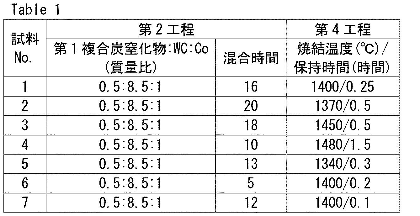
(組成)
得られた切削工具(超硬合金)において、第2硬質相粒子の芯部、周辺部および第3硬質相粒子の組成を上述の方法によりEDXを用いて分析した。第2硬質相粒子の芯部および第3硬質相粒子の組成は、表2に示した第1複合炭窒化物の組成と一致した。第2硬質相粒子の周辺部の組成を表2の「周辺部の組成」欄に示す。なお、周辺部は芯部の少なくとも一部を被覆していることを電子顕微鏡像において目視により確認した。
得られた切削工具(超硬合金)において、第2硬質相粒子および第3硬質相粒子の分散度および第3硬質相粒子の個数百分率を上述の方法により算出した。結果を表2の「分散度」および「第3硬質相粒子の個数百分率」欄に示す。
得られた切削工具(超硬合金)において、周辺部の平均厚みを上述の方法により測定した。結果を表2の「周辺部の平均厚み(nm)」欄に示す。
得られた切削工具(超硬合金)において、芯部の平均粒径および第3硬質相粒子の平均粒径を上述の方法により測定した。結果を表2の「芯部の平均粒径(μm)」および「第3硬質相粒子の平均粒径(μm)」欄に示す。
得られた切削工具(超硬合金)において、第2硬質相粒子および第3硬質相粒子の体積比率を上述の方法で測定した。結果を表2の「第2硬質相粒子(体積%)」および「第3硬質相粒子(体積%)」欄に示す。
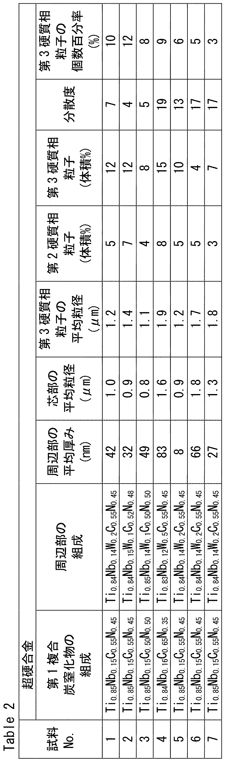
得られた切削工具に対し、下記の条件の下で耐欠損性試験および耐鋼反応性試験を行なった。
被削材:SCM435穴付き
周速 :200m/min
送り :0.5mm/rev
切込み:2mm
切削油:なし。
被削材:SCM435
周速 :100m/min
送り :0.15mm/rev
切込み:1.5mm
切削油:なし。
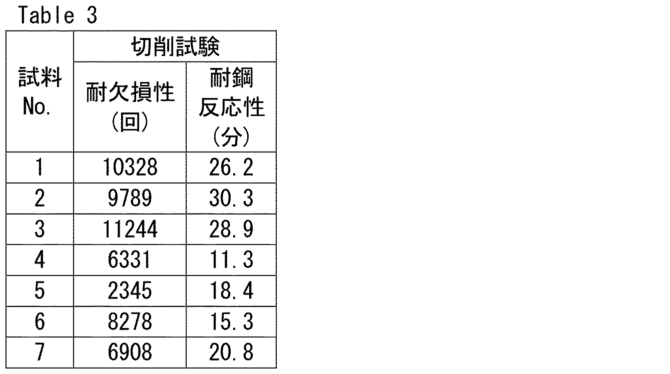
試料1~試料3は実施例に該当する。試料4~試料6は、分散度が10超であり、比較例に該当する。試料7は、分散度が10超、かつ、第3硬質相粒子の個数百分率が5%未満であり比較例に該当する。試料1~試料3(実施例)の切削工具は、試料4~試料7(比較例)の切削工具に比べ、耐欠損性および耐鋼反応性に優れることが確認された。
Claims (8)
- 第1硬質相粒子と、第2硬質相粒子と、第3硬質相粒子と、金属結合相と、を備える超硬合金であって、
前記第1硬質相粒子は、炭化タングステンを含み、
前記第2硬質相粒子は、粒状の芯部と、前記芯部の少なくとも一部を被覆する周辺部と、を有し、
前記芯部は、Ti1-X-ZNbXMZC1-YNYで示される第1複合炭窒化物からなり、
前記周辺部は、前記芯部と組成が異なり、少なくともチタン、ニオブおよびタングステンを含む炭窒化物である第2複合炭窒化物からなり、
前記Mは、バナジウム、クロムおよびモリブデンからなる群より選択される少なくとも1種の元素を示し、
前記Xは、0.1以上0.2以下であり、
前記Yは、0.3以上0.6以下であり、
前記Zは、0以上0.02以下であり、
前記第3硬質相粒子は、前記第1複合炭窒化物からなり、
前記金属結合相は、鉄族元素を含み、
前記超硬合金は合計70個の単位領域を有し、
前記合計70個の前記単位領域は、前記超硬合金の任意の断面を1500倍の倍率で撮影した電子顕微鏡像中に、1辺が8μmである正方形からなる前記単位領域を縦方向に7個、かつ横方向に10個連続して並べることにより設けられ、
前記合計70個の前記単位領域のうち、百分率が0.43%未満または2.43%超となる前記単位領域の数は10以下であり、
前記百分率は、それぞれの前記単位領域における、前記合計70個の前記単位領域の内部に存する前記第2硬質相粒子の個数および前記第3硬質相粒子の個数の合計個数に対する、前記単位領域の内部に存する前記第2硬質相粒子の個数および前記第3硬質相粒子の個数の合計個数の百分率であり、
前記単位領域の内部に存する前記第2硬質相粒子の個数は、前記単位領域の内部に存する芯部の粒径が0.2μm以上3μm以下の前記第2硬質相粒子の個数であり、
前記単位領域の内部に存する前記第3硬質相粒子の個数は、前記単位領域の内部に存する粒径が0.5μm以上2.5μm以下の前記第3硬質相粒子の個数であり、
前記超硬合金は、合計70個の前記単位領域のうち、縦方向の4行目に存在する合計10個の前記単位領域において、芯部の粒径が0.2μm以上3μm以下の前記第2硬質相粒子の個数、および、粒径が0.5μm以上2.5μm以下の前記第3硬質相粒子の個数の合計個数に対する、粒径が0.5μm以上2.5μm以下の前記第3硬質相粒子の個数の百分率が5%以上15%以下である、超硬合金。 - 前記周辺部の平均厚みは、10nm以上100nm以下である、請求項1に記載の超硬合金。
- 前記芯部の平均粒径は、0.2μm以上2μm以下である、請求項1または請求項2に記載の超硬合金。
- 前記第3硬質相粒子の平均粒径は、0.5μm以上2.5μm以下である、請求項1から請求項3のいずれか1項に記載の超硬合金。
- 前記超硬合金は、前記第2硬質相粒子を2体積%以上10体積%以下含む、請求項1から請求項4のいずれか1項に記載の超硬合金。
- 前記超硬合金は、前記第3硬質相粒子を3体積%以上20体積%以下含む、請求項1から請求項5のいずれか1項に記載の超硬合金。
- 請求項1から請求項6のいずれか1項に記載の超硬合金を含む、切削工具。
- 前記超硬合金からなる基材と、前記基材を被覆する被膜とを含む、請求項7に記載の切削工具。
Priority Applications (4)
| Application Number | Priority Date | Filing Date | Title |
|---|---|---|---|
| CN202180008053.6A CN114901846B (zh) | 2020-04-15 | 2021-03-23 | 硬质合金以及包含该硬质合金的切削工具 |
| US17/599,570 US11441209B2 (en) | 2020-04-15 | 2021-03-23 | Cemented carbide and cutting tool including same |
| JP2021540170A JP6969732B1 (ja) | 2020-04-15 | 2021-03-23 | 超硬合金およびそれを含む切削工具 |
| EP21788352.9A EP4074853B1 (en) | 2020-04-15 | 2021-03-23 | Cemented carbide and cutting tool including same |
Applications Claiming Priority (2)
| Application Number | Priority Date | Filing Date | Title |
|---|---|---|---|
| JP2020072993 | 2020-04-15 | ||
| JP2020-072993 | 2020-04-15 |
Publications (2)
| Publication Number | Publication Date |
|---|---|
| WO2021210357A1 true WO2021210357A1 (ja) | 2021-10-21 |
| WO2021210357A9 WO2021210357A9 (ja) | 2021-12-23 |
Family
ID=78084054
Family Applications (1)
| Application Number | Title | Priority Date | Filing Date |
|---|---|---|---|
| PCT/JP2021/011861 Ceased WO2021210357A1 (ja) | 2020-04-15 | 2021-03-23 | 超硬合金およびそれを含む切削工具 |
Country Status (5)
| Country | Link |
|---|---|
| US (1) | US11441209B2 (ja) |
| EP (1) | EP4074853B1 (ja) |
| JP (1) | JP6969732B1 (ja) |
| CN (1) | CN114901846B (ja) |
| WO (1) | WO2021210357A1 (ja) |
Cited By (2)
| Publication number | Priority date | Publication date | Assignee | Title |
|---|---|---|---|---|
| US11913096B1 (en) | 2022-11-18 | 2024-02-27 | Sumitomo Electric Industries, Ltd. | Cemented carbide and tool containing the same |
| WO2026048532A1 (ja) * | 2024-08-28 | 2026-03-05 | 京セラ株式会社 | 超硬合金、切削工具用ブランク、切削工具、および切削加工物の製造方法 |
Families Citing this family (2)
| Publication number | Priority date | Publication date | Assignee | Title |
|---|---|---|---|---|
| WO2023139695A1 (ja) * | 2022-01-19 | 2023-07-27 | 住友電気工業株式会社 | 超硬合金およびそれを含む工具 |
| CN119365618A (zh) * | 2023-05-12 | 2025-01-24 | 住友电工硬质合金株式会社 | 硬质合金以及包含硬质合金的工具 |
Citations (7)
| Publication number | Priority date | Publication date | Assignee | Title |
|---|---|---|---|---|
| WO2011136197A1 (ja) | 2010-04-26 | 2011-11-03 | 株式会社タンガロイ | サーメットおよび被覆サーメット |
| JP2012086298A (ja) * | 2010-10-19 | 2012-05-10 | Mitsubishi Materials Corp | 鋼の高速断続切削において優れた耐欠損性を発揮する表面被覆wc基超硬合金製切削工具 |
| JP2016087742A (ja) * | 2014-11-05 | 2016-05-23 | 株式会社タンガロイ | サーメット工具および被覆サーメット工具 |
| WO2017191744A1 (ja) | 2016-05-02 | 2017-11-09 | 住友電気工業株式会社 | 超硬合金、及び切削工具 |
| WO2019207876A1 (ja) * | 2018-04-26 | 2019-10-31 | 住友電気工業株式会社 | 超硬合金、それを含む切削工具および超硬合金の製造方法 |
| WO2020070978A1 (ja) * | 2018-10-04 | 2020-04-09 | 住友電工ハードメタル株式会社 | 超硬合金、それを含む切削工具および超硬合金の製造方法 |
| JP2020072993A (ja) | 2020-01-27 | 2020-05-14 | 株式会社セガゲームス | ゲーム装置 |
Family Cites Families (11)
| Publication number | Priority date | Publication date | Assignee | Title |
|---|---|---|---|---|
| JP2008132570A (ja) * | 2006-11-29 | 2008-06-12 | Kyocera Corp | 切削工具 |
| US7810588B2 (en) * | 2007-02-23 | 2010-10-12 | Baker Hughes Incorporated | Multi-layer encapsulation of diamond grit for use in earth-boring bits |
| US8056652B2 (en) * | 2007-06-25 | 2011-11-15 | Smith International, Inc. | Barrier coated granules for improved hardfacing material using atomic layer deposition |
| WO2010136207A1 (en) * | 2009-05-29 | 2010-12-02 | Metalogenia, S.L. | Wear element for earth/rock working operations with enhanced wear resistance |
| CN102470446A (zh) * | 2009-06-30 | 2012-05-23 | 株式会社图格莱 | 金属陶瓷和被覆金属陶瓷 |
| CN103635599B (zh) * | 2011-06-27 | 2016-03-30 | 京瓷株式会社 | 硬质合金及切削工具 |
| JP5946017B2 (ja) * | 2012-05-30 | 2016-07-05 | 三菱マテリアル株式会社 | 高速断続切削加工で硬質被覆層がすぐれた耐チッピング性を発揮する表面被覆切削工具 |
| US10066277B2 (en) * | 2015-06-12 | 2018-09-04 | Tungaloy Corporation | Cemented carbide and coated cemented carbide |
| US10343212B2 (en) * | 2016-01-19 | 2019-07-09 | Wenhui Jiang | Hardfacing containing tungsten carbide particles with barrier coating and methods of making the same |
| WO2018193659A1 (ja) * | 2017-04-19 | 2018-10-25 | 住友電気工業株式会社 | 超硬合金、それを含む切削工具および超硬合金の製造方法 |
| US12220744B2 (en) * | 2018-06-20 | 2025-02-11 | Desktop Metal, Inc. | Methods and compositions for the preparation of powders for binder-based three-dimensional additive metal manufacturing |
-
2021
- 2021-03-23 US US17/599,570 patent/US11441209B2/en active Active
- 2021-03-23 JP JP2021540170A patent/JP6969732B1/ja active Active
- 2021-03-23 WO PCT/JP2021/011861 patent/WO2021210357A1/ja not_active Ceased
- 2021-03-23 EP EP21788352.9A patent/EP4074853B1/en active Active
- 2021-03-23 CN CN202180008053.6A patent/CN114901846B/zh active Active
Patent Citations (7)
| Publication number | Priority date | Publication date | Assignee | Title |
|---|---|---|---|---|
| WO2011136197A1 (ja) | 2010-04-26 | 2011-11-03 | 株式会社タンガロイ | サーメットおよび被覆サーメット |
| JP2012086298A (ja) * | 2010-10-19 | 2012-05-10 | Mitsubishi Materials Corp | 鋼の高速断続切削において優れた耐欠損性を発揮する表面被覆wc基超硬合金製切削工具 |
| JP2016087742A (ja) * | 2014-11-05 | 2016-05-23 | 株式会社タンガロイ | サーメット工具および被覆サーメット工具 |
| WO2017191744A1 (ja) | 2016-05-02 | 2017-11-09 | 住友電気工業株式会社 | 超硬合金、及び切削工具 |
| WO2019207876A1 (ja) * | 2018-04-26 | 2019-10-31 | 住友電気工業株式会社 | 超硬合金、それを含む切削工具および超硬合金の製造方法 |
| WO2020070978A1 (ja) * | 2018-10-04 | 2020-04-09 | 住友電工ハードメタル株式会社 | 超硬合金、それを含む切削工具および超硬合金の製造方法 |
| JP2020072993A (ja) | 2020-01-27 | 2020-05-14 | 株式会社セガゲームス | ゲーム装置 |
Non-Patent Citations (4)
| Title |
|---|
| See also references of EP4074853A4 |
| SHIGEHIKO TANAKA ET AL., OTSU'S DISCRIMINANT ANALYSIS METHOD WITH GRAY LEVEL CO-OCCURRENCE HISTOGRAM |
| SHIGEHIKO TANAKA, MEETING ON IMAGE RECOGNITION AND UNDERSTANDING (MIRU, vol. 1-3, July 2011 (2011-07-01), pages 93 - 96 |
| SHIGEHIKO TANAKA, MEETING ON IMAGE RECOGNITION AND UNDERSTANDING (MIRU2011 |
Cited By (4)
| Publication number | Priority date | Publication date | Assignee | Title |
|---|---|---|---|---|
| US11913096B1 (en) | 2022-11-18 | 2024-02-27 | Sumitomo Electric Industries, Ltd. | Cemented carbide and tool containing the same |
| JP7452762B1 (ja) * | 2022-11-18 | 2024-03-19 | 住友電気工業株式会社 | 超硬合金およびそれを含む工具 |
| WO2024105882A1 (ja) * | 2022-11-18 | 2024-05-23 | 住友電気工業株式会社 | 超硬合金およびそれを含む工具 |
| WO2026048532A1 (ja) * | 2024-08-28 | 2026-03-05 | 京セラ株式会社 | 超硬合金、切削工具用ブランク、切削工具、および切削加工物の製造方法 |
Also Published As
| Publication number | Publication date |
|---|---|
| JPWO2021210357A1 (ja) | 2021-10-21 |
| WO2021210357A9 (ja) | 2021-12-23 |
| JP6969732B1 (ja) | 2021-11-24 |
| EP4074853B1 (en) | 2025-07-16 |
| CN114901846B (zh) | 2023-06-30 |
| EP4074853A1 (en) | 2022-10-19 |
| US20220090237A1 (en) | 2022-03-24 |
| CN114901846A (zh) | 2022-08-12 |
| US11441209B2 (en) | 2022-09-13 |
| EP4074853A4 (en) | 2023-09-20 |
Similar Documents
| Publication | Publication Date | Title |
|---|---|---|
| JP6969732B1 (ja) | 超硬合金およびそれを含む切削工具 | |
| JP6696664B1 (ja) | 超硬合金、それを含む切削工具および超硬合金の製造方法 | |
| JP6992808B2 (ja) | 超硬合金、それを含む切削工具および超硬合金の製造方法 | |
| JP7115486B2 (ja) | 超硬合金、それを含む切削工具および超硬合金の製造方法 | |
| JP7020477B2 (ja) | サーメット、それを含む切削工具およびサーメットの製造方法 | |
| JP7098969B2 (ja) | 超硬合金、それを含む切削工具、超硬合金の製造方法および切削工具の製法方法 |
Legal Events
| Date | Code | Title | Description |
|---|---|---|---|
| ENP | Entry into the national phase |
Ref document number: 2021540170 Country of ref document: JP Kind code of ref document: A |
|
| 121 | Ep: the epo has been informed by wipo that ep was designated in this application |
Ref document number: 21788352 Country of ref document: EP Kind code of ref document: A1 |
|
| ENP | Entry into the national phase |
Ref document number: 2021788352 Country of ref document: EP Effective date: 20220715 |
|
| NENP | Non-entry into the national phase |
Ref country code: DE |
|
| WWG | Wipo information: grant in national office |
Ref document number: 2021788352 Country of ref document: EP |