WO2021214362A1 - Dispositivo de cimentación para torre eólica y método de montaje - Google Patents
Dispositivo de cimentación para torre eólica y método de montaje Download PDFInfo
- Publication number
- WO2021214362A1 WO2021214362A1 PCT/ES2021/070262 ES2021070262W WO2021214362A1 WO 2021214362 A1 WO2021214362 A1 WO 2021214362A1 ES 2021070262 W ES2021070262 W ES 2021070262W WO 2021214362 A1 WO2021214362 A1 WO 2021214362A1
- Authority
- WO
- WIPO (PCT)
- Prior art keywords
- wind tower
- lower face
- upper face
- main body
- foundation
- Prior art date
- Legal status (The legal status is an assumption and is not a legal conclusion. Google has not performed a legal analysis and makes no representation as to the accuracy of the status listed.)
- Ceased
Links
Classifications
-
- F—MECHANICAL ENGINEERING; LIGHTING; HEATING; WEAPONS; BLASTING
- F03—MACHINES OR ENGINES FOR LIQUIDS; WIND, SPRING, OR WEIGHT MOTORS; PRODUCING MECHANICAL POWER OR A REACTIVE PROPULSIVE THRUST, NOT OTHERWISE PROVIDED FOR
- F03D—WIND MOTORS
- F03D13/00—Assembly, mounting or commissioning of wind motors; Arrangements specially adapted for transporting wind motor components
- F03D13/20—Arrangements for mounting or supporting wind motors; Masts or towers for wind motors
- F03D13/25—Arrangements for mounting or supporting wind motors; Masts or towers for wind motors specially adapted for offshore installation
-
- E—FIXED CONSTRUCTIONS
- E02—HYDRAULIC ENGINEERING; FOUNDATIONS; SOIL SHIFTING
- E02D—FOUNDATIONS; EXCAVATIONS; EMBANKMENTS; UNDERGROUND OR UNDERWATER STRUCTURES
- E02D27/00—Foundations as substructures
- E02D27/32—Foundations for special purposes
- E02D27/42—Foundations for poles, masts or chimneys
-
- E—FIXED CONSTRUCTIONS
- E02—HYDRAULIC ENGINEERING; FOUNDATIONS; SOIL SHIFTING
- E02D—FOUNDATIONS; EXCAVATIONS; EMBANKMENTS; UNDERGROUND OR UNDERWATER STRUCTURES
- E02D27/00—Foundations as substructures
- E02D27/32—Foundations for special purposes
- E02D27/52—Submerged foundations, i.e. submerged in open water
-
- E—FIXED CONSTRUCTIONS
- E02—HYDRAULIC ENGINEERING; FOUNDATIONS; SOIL SHIFTING
- E02D—FOUNDATIONS; EXCAVATIONS; EMBANKMENTS; UNDERGROUND OR UNDERWATER STRUCTURES
- E02D23/00—Caissons; Construction or placing of caissons
- E02D23/02—Caissons able to be floated on water and to be lowered into water in situ
-
- E—FIXED CONSTRUCTIONS
- E02—HYDRAULIC ENGINEERING; FOUNDATIONS; SOIL SHIFTING
- E02D—FOUNDATIONS; EXCAVATIONS; EMBANKMENTS; UNDERGROUND OR UNDERWATER STRUCTURES
- E02D27/00—Foundations as substructures
- E02D27/01—Flat foundations
- E02D27/04—Flat foundations in water or on quicksand
- E02D27/06—Floating caisson foundations
-
- E—FIXED CONSTRUCTIONS
- E02—HYDRAULIC ENGINEERING; FOUNDATIONS; SOIL SHIFTING
- E02D—FOUNDATIONS; EXCAVATIONS; EMBANKMENTS; UNDERGROUND OR UNDERWATER STRUCTURES
- E02D27/00—Foundations as substructures
- E02D27/32—Foundations for special purposes
- E02D27/52—Submerged foundations, i.e. submerged in open water
- E02D27/525—Submerged foundations, i.e. submerged in open water using elements penetrating the underwater ground
-
- E—FIXED CONSTRUCTIONS
- E02—HYDRAULIC ENGINEERING; FOUNDATIONS; SOIL SHIFTING
- E02D—FOUNDATIONS; EXCAVATIONS; EMBANKMENTS; UNDERGROUND OR UNDERWATER STRUCTURES
- E02D5/00—Bulkheads, piles, or other structural elements specially adapted to foundation engineering
- E02D5/18—Bulkheads or similar walls made solely of concrete in situ
-
- E—FIXED CONSTRUCTIONS
- E02—HYDRAULIC ENGINEERING; FOUNDATIONS; SOIL SHIFTING
- E02D—FOUNDATIONS; EXCAVATIONS; EMBANKMENTS; UNDERGROUND OR UNDERWATER STRUCTURES
- E02D5/00—Bulkheads, piles, or other structural elements specially adapted to foundation engineering
- E02D5/74—Means for anchoring structural elements or bulkheads
-
- E—FIXED CONSTRUCTIONS
- E02—HYDRAULIC ENGINEERING; FOUNDATIONS; SOIL SHIFTING
- E02D—FOUNDATIONS; EXCAVATIONS; EMBANKMENTS; UNDERGROUND OR UNDERWATER STRUCTURES
- E02D7/00—Methods or apparatus for placing sheet pile bulkheads, piles, mouldpipes, or other moulds
- E02D7/28—Placing of hollow pipes or mould pipes by means arranged inside the piles or pipes
-
- E—FIXED CONSTRUCTIONS
- E04—BUILDING
- E04H—BUILDINGS OR LIKE STRUCTURES FOR PARTICULAR PURPOSES; SWIMMING OR SPLASH BATHS OR POOLS; MASTS; FENCING; TENTS OR CANOPIES, IN GENERAL
- E04H12/00—Towers; Masts or poles; Chimney stacks; Water-towers; Methods of erecting such structures
- E04H12/22—Sockets or holders for poles or posts
- E04H12/2238—Sockets or holders for poles or posts to be placed on the ground
- E04H12/2246—Sockets or holders for poles or posts to be placed on the ground filled with water, sand or the like
-
- F—MECHANICAL ENGINEERING; LIGHTING; HEATING; WEAPONS; BLASTING
- F03—MACHINES OR ENGINES FOR LIQUIDS; WIND, SPRING, OR WEIGHT MOTORS; PRODUCING MECHANICAL POWER OR A REACTIVE PROPULSIVE THRUST, NOT OTHERWISE PROVIDED FOR
- F03D—WIND MOTORS
- F03D13/00—Assembly, mounting or commissioning of wind motors; Arrangements specially adapted for transporting wind motor components
- F03D13/20—Arrangements for mounting or supporting wind motors; Masts or towers for wind motors
- F03D13/22—Foundations specially adapted for wind motors
-
- F—MECHANICAL ENGINEERING; LIGHTING; HEATING; WEAPONS; BLASTING
- F03—MACHINES OR ENGINES FOR LIQUIDS; WIND, SPRING, OR WEIGHT MOTORS; PRODUCING MECHANICAL POWER OR A REACTIVE PROPULSIVE THRUST, NOT OTHERWISE PROVIDED FOR
- F03D—WIND MOTORS
- F03D13/00—Assembly, mounting or commissioning of wind motors; Arrangements specially adapted for transporting wind motor components
- F03D13/40—Arrangements or methods specially adapted for transporting wind motor components
-
- F—MECHANICAL ENGINEERING; LIGHTING; HEATING; WEAPONS; BLASTING
- F05—INDEXING SCHEMES RELATING TO ENGINES OR PUMPS IN VARIOUS SUBCLASSES OF CLASSES F01-F04
- F05B—INDEXING SCHEME RELATING TO WIND, SPRING, WEIGHT, INERTIA OR LIKE MOTORS, TO MACHINES OR ENGINES FOR LIQUIDS COVERED BY SUBCLASSES F03B, F03D AND F03G
- F05B2240/00—Components
- F05B2240/90—Mounting on supporting structures or systems
- F05B2240/95—Mounting on supporting structures or systems offshore
-
- F—MECHANICAL ENGINEERING; LIGHTING; HEATING; WEAPONS; BLASTING
- F05—INDEXING SCHEMES RELATING TO ENGINES OR PUMPS IN VARIOUS SUBCLASSES OF CLASSES F01-F04
- F05B—INDEXING SCHEME RELATING TO WIND, SPRING, WEIGHT, INERTIA OR LIKE MOTORS, TO MACHINES OR ENGINES FOR LIQUIDS COVERED BY SUBCLASSES F03B, F03D AND F03G
- F05B2260/00—Function
- F05B2260/02—Transport, e.g. specific adaptations or devices for conveyance
-
- Y—GENERAL TAGGING OF NEW TECHNOLOGICAL DEVELOPMENTS; GENERAL TAGGING OF CROSS-SECTIONAL TECHNOLOGIES SPANNING OVER SEVERAL SECTIONS OF THE IPC; TECHNICAL SUBJECTS COVERED BY FORMER USPC CROSS-REFERENCE ART COLLECTIONS [XRACs] AND DIGESTS
- Y02—TECHNOLOGIES OR APPLICATIONS FOR MITIGATION OR ADAPTATION AGAINST CLIMATE CHANGE
- Y02E—REDUCTION OF GREENHOUSE GAS [GHG] EMISSIONS, RELATED TO ENERGY GENERATION, TRANSMISSION OR DISTRIBUTION
- Y02E10/00—Energy generation through renewable energy sources
- Y02E10/70—Wind energy
- Y02E10/72—Wind turbines with rotation axis in wind direction
-
- Y—GENERAL TAGGING OF NEW TECHNOLOGICAL DEVELOPMENTS; GENERAL TAGGING OF CROSS-SECTIONAL TECHNOLOGIES SPANNING OVER SEVERAL SECTIONS OF THE IPC; TECHNICAL SUBJECTS COVERED BY FORMER USPC CROSS-REFERENCE ART COLLECTIONS [XRACs] AND DIGESTS
- Y02—TECHNOLOGIES OR APPLICATIONS FOR MITIGATION OR ADAPTATION AGAINST CLIMATE CHANGE
- Y02E—REDUCTION OF GREENHOUSE GAS [GHG] EMISSIONS, RELATED TO ENERGY GENERATION, TRANSMISSION OR DISTRIBUTION
- Y02E10/00—Energy generation through renewable energy sources
- Y02E10/70—Wind energy
- Y02E10/727—Offshore wind turbines
-
- Y—GENERAL TAGGING OF NEW TECHNOLOGICAL DEVELOPMENTS; GENERAL TAGGING OF CROSS-SECTIONAL TECHNOLOGIES SPANNING OVER SEVERAL SECTIONS OF THE IPC; TECHNICAL SUBJECTS COVERED BY FORMER USPC CROSS-REFERENCE ART COLLECTIONS [XRACs] AND DIGESTS
- Y10—TECHNICAL SUBJECTS COVERED BY FORMER USPC
- Y10S—TECHNICAL SUBJECTS COVERED BY FORMER USPC CROSS-REFERENCE ART COLLECTIONS [XRACs] AND DIGESTS
- Y10S248/00—Supports
- Y10S248/91—Weighted base
Definitions
- the present invention is framed within the wind platforms installed in the sea, as well as the necessary means to carry out said installation.
- the devices can be with a floating or heavy foundation.
- the former are more bulky, but do not need very powerful means to move them to the installation point.
- the latter are smaller, but need large ships to transport them to the point of installation.
- the assembly can be carried out on the ground (moving the whole assembly to the installation point) or at the installation point itself (moving the foundation and the tower independently).
- the technical problem relevant to the present invention relates to heavy foundation devices, intended to be fully sunk.
- the processes of assembling the tower, displacement of the foundation or set and sinking of the foundation are critical, and have their own technical requirements related to buoyancy, inertia and equipment necessary for its use, having nothing to do with those devices intended. to provide a floating foundation.
- the present invention provides an alternative solution for the problems related to devices dedicated to the installation process of an offshore wind tower with a heavy foundation.
- the present invention provides an alternative solution to the problem proposed above by means of a device according to claim 1.
- the dependent claims define preferred embodiments of the invention.
- An object of the present invention refers to a foundation device for a wind tower configured to be supported on the seabed comprising a hollow main body comprising a lower face intended to rest on the seabed and an upper face opposite to the lower face; the device characterized in that both the lower face and the upper face comprise a hollow space inside, therefore each of the faces comprises an outer perimeter and an inner perimeter; the main body further comprises an outer side wall arranged between the outer perimeter of the lower face and the outer perimeter of the upper face and an inner side wall between the inner perimeter of the lower face and the inner perimeter of the upper face; and the device further comprises a plurality of columns projecting from the upper face of the main body.
- the vertical columns provide the necessary flotation during the immersion of the structure. This arrangement increases the metacentric height of the main body and therefore the stability of the structure while it is ballasting towards the seabed.
- the device additionally comprises a floor slab located on the lower face, the floor slab being a polygonal surface without interior spaces.
- This floor slab is intended to cover the polygonal ring formed between the upper and lower faces. In this way, the main structure continues to be ring, but with a floor, so that, when the device is thrown into the sea, the water does not penetrate into the inner hollow of the ring, reducing the draft in port.
- the distance between the upper face and the lower face is at least four times greater than the height of the floor slab, where the height of the floor slab is measured in a direction parallel to the distance between the upper face and the underside.
- the hollow space inside the upper face and the lower face is such that the ratio between the transverse metacentric radius of the device and the cube root of the displacement volume is greater than 0.003.
- One of the main advantages of the invention is that a greater metacentric radius is achieved than in the case of traditional solutions.
- One way to quantify this advantage is with a dimensionless parameter that consists of dividing the transverse metacentric radius by a characteristic length, calculated as the cube root of the volume of displacement.
- This dimensionless parameter independent of the size of the foundation device, is higher in devices according to the present invention compared to known devices. The size of the interior gap allows this increase and this advantage.
- At least one of the columns is hollow.
- the interior of at least one of the columns is in communication with the interior of the main body.
- one of the columns is an anchoring column and has an anchoring surface with anchoring means configured to receive the installation of a wind tower.
- the device additionally comprises a plurality of first plates anchored in a reinforcing ring of the anchoring column; a plurality of second plates adapted to be fixed to a reinforcing ring of a wind tower; a plurality of lifting elements each configured to exert a pressure between one of the first plates and one of the second plates.
- These adjustment elements allow a tilt adjustment once the tower is positioned on the anchor column.
- the inclination adjustment is usually carried out once the foundation device is already supported on the seabed, in order to be able to take a reliable reference to the vertical.
- the reinforcement rings allow to absorb the stresses produced by the force of the lifting elements.
- At least a portion of one of the lifting elements is embedded on a second plate.
- the pistons of the lifting element can serve as a guide during the leveling of the wind tower, preventing its unbalance.
- the device further comprises reversible pumping means for selectively filling or emptying the interior of the main body.
- the installation of pumping means that allow both the filling and the emptying of the interior of the main body is an advantage: the filling function allows controlling the ballasting process, while the emptying function allows the foundation device to be re-floated for dismantling or revision, allowing its subsequent reuse.
- both the upper face and the lower face have an annular polygon shape, in which both the inner perimeter and the outer perimeter are polygons with the same number of sides.
- both the upper face and the lower face have a ring shape, so that both the inner perimeter and the outer perimeter are closed curves, such as circles or ellipses.
- a single sharp turn can offer other benefits, such as less drag in the water.
- the main body is made of concrete.
- the invention provides a method of installing a wind tower, comprising the steps of providing a foundation device according to any of the preceding claims providing a wind tower place the assembly formed by the foundation device and the wind tower at an installation point located in the sea fill the hollow main body with a fluid, so that the assembly formed by the foundation device and the wind tower collapses .
- This method allows great stability while moving the foundation device to the point of installation, due to its particular geometry with a hole inside.
- This method is compatible both for the option of installing the wind tower on the foundation assembly on land and then moving the entire assembly to the installation point and for the option of mounting the wind tower afloat and then proceeding to its transportation and subsequent ballasted.
- the method comprises the steps of joining the wind tower to the installation column of the foundation device, and moving the assembly formed by the foundation device and the wind tower to an installation point located in the sea.
- the tower is attached to the installation column before moving the entire assembly by sea to the installation point.
- the union of the tower on land facilitates the process and avoids the movement of complex machines to the point of installation. Furthermore, on land the joint is not subject to wave movement.
- the method additionally comprises the steps of effecting by means of a lifting device a pressure between a first plate and a second plate to vary the inclination of the wind tower with respect to the anchoring column, creating a leveling gap between the anchoring surface and the wind tower insert a clamping element into the leveling hole.
- Figures 1a and 1b show two particular examples of foundation devices for a wind tower according to the invention.
- Figures 2a to 2d show different stages of an installation method according to the invention.
- Figure 3 shows a detail of the connection between the column of a foundation device and a wind tower, in which a system for correcting the inclination of a foundation device according to the invention can be seen.
- Figure 4 shows an alternative embodiment of a foundation device.
- Figures 1a and 1b show two particular examples of foundation devices 10 for a wind tower according to the invention.
- Each device 10 comprises a hollow main body 1 with a lower face 2 intended to rest on the seabed and an upper face 3 opposite the lower face 2.
- Both the lower face 2 and the upper face 3 comprise a hollow space inside them, each of the faces therefore comprising an outer perimeter 21, 31 and an inner perimeter 22, 32.
- both the upper face 3 and the lower face 2 have an annular polygon shape.
- this polygonal shape can be altered in other embodiments.
- Figures 1a and 1b show a hexagon and a square, but it can well be done with triangles, pentagons, heptagons, octagons, etc. or to be done in closed curves, such as circles, ovals or ellipses.
- the main body 1 additionally comprises an outer lateral wall 4 arranged between the outer perimeter 21 of the lower face 2 and the perimeter outer 31 of the upper face 3 and an inner side wall 5 between the inner perimeter 22 of the lower face 2 and the inner perimeter 32 of the upper face 3.
- the transverse metacentric radius of the assembly understood as the quotient between the transverse inertia of the device with respect to a horizontal axis and the displacement volume, is higher than in known solutions, allowing the same stability to be obtained with a weight much lower, facilitating the movement of the assembly and reducing the ballasting time.
- the foundation device 10 also comprises a plurality of columns 6 projecting from the upper face of the main body. These columns 6 are hollow, and their interior is in communication with the interior of the main body.
- the vertical flotation columns allow the foundation device 10 to be submerged in due course without the aid of high tonnage auxiliary vessels, simply by adding ballast water. These columns maintain the values of the inertia in the flotation in adequate stability values, resulting as a main advantage the reduction of the installation costs, both in materials and in auxiliary means, being able to carry out the immersion process in a safe, efficient and fast.
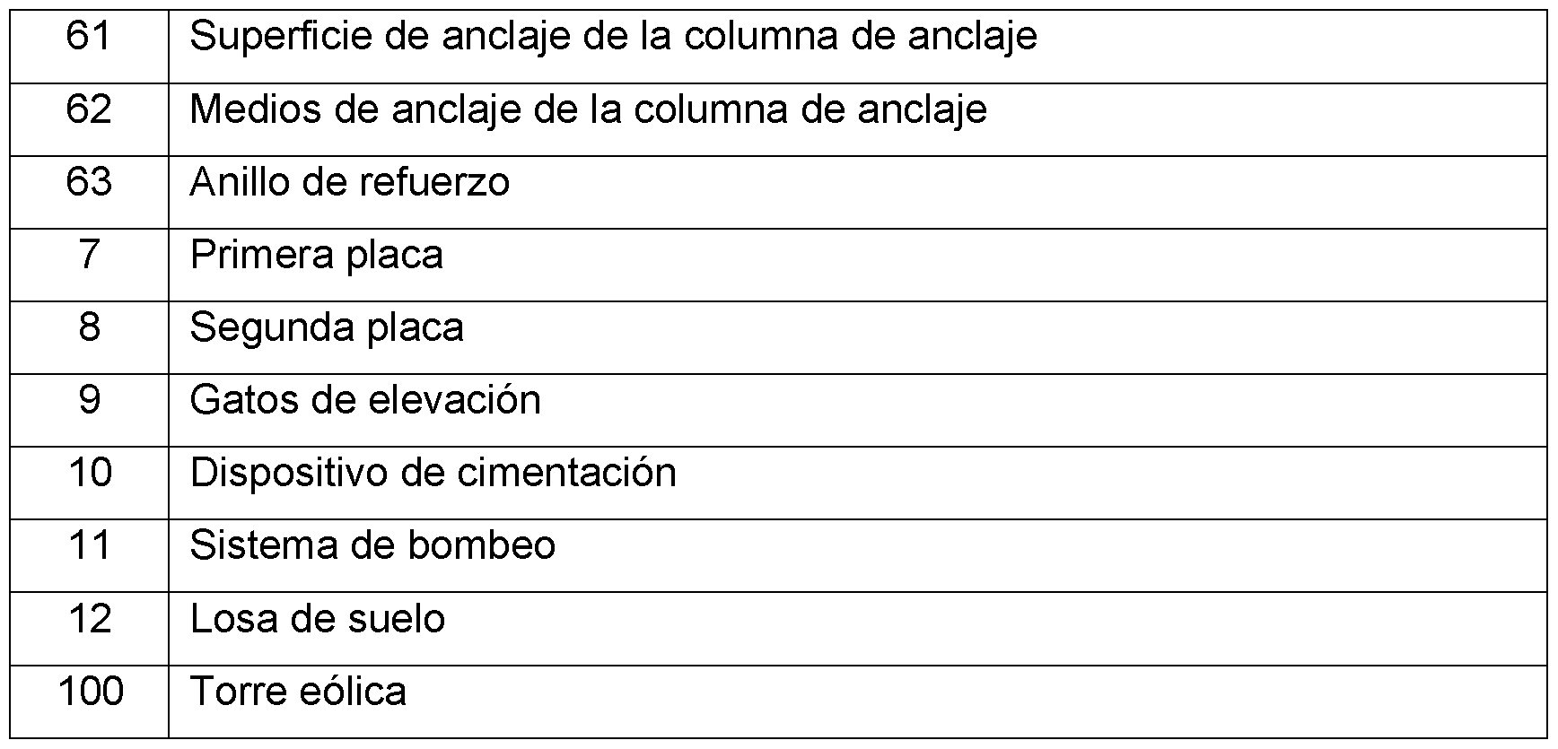
- One of these columns is an anchor column 60 and has an anchoring surface 61 with anchoring means 62 configured to receive the installation of a wind tower.
- These anchoring means 62 are configured to provide a bolted connection between the column and the tower.
- the foundation device 10 also includes reversible pumping means 11 to selectively fill or empty the interior of the main body 1 during installation and ballasting and dismantling or floating operations.
- the pumping system is configured for reversible operation, allowing the shedding of the structure and its subsequent transport for dismantling once the useful life of the platform has concluded. For this, its design is protected against corrosion and both the pumps and some series of valves are replaceable during the life cycle of the structure.
- the location of the pump room is located in a dry room located in the foundation device 10.
- Both the main body 1 and the columns 6 are made of concrete.
- FIGS 2a to 2d show different stages of an installation method according to the invention.
- Figure 2a shows the assembly formed by the foundation device 10 and a wind tower 100, which has been mounted on the installation column 60 on the ground.
- the pumping system 11 will be activated to fill the main body 1 with water. This will result in the submersion of the platform, as illustrated in figure 2d. During this process, only the assistance of the tugboats will be necessary to keep the platform in position, due to the flotation columns that, as explained, guarantee that no additional auxiliary means are necessary during the dive.
- Figure 3 shows a detail of the connection between the anchor column 60 and the wind tower 100, in which a system for correcting the inclination of the wind tower 100 can be seen.
- This system includes elements in both the anchor column 60 and the wind tower 100: a plurality of first plates 7 anchored to a reinforcing ring 63 of anchor column 60; a plurality of second plates 8 fixed to a reinforcing ring 63 of the wind tower 100; a plurality of hydraulic lifting cylinders 9 each configured to exert a pressure between one of the first plates 7 and one of the second plates 8.
- the plates 7, 8, arranged perpendicular to the respective reinforcement ring 63, are responsible for housing the body or base of the hydraulic cylinders 9.
- the plates 7, 8 perpendicular to the reinforcement rings 63 are responsible for receiving the hydraulic cylinder piston force 9.
- the pistons themselves act as a guide, embedding the hydraulic cylinder 9 on the plate 8 of the tower 100.
- the hydraulic cylinder 9 only acts on the plate 8 of the tower 100
- auxiliary guides can be used to prevent tower 100 from destabilizing during the leveling process.
- this correction step involves using the hydraulic lifting cylinders 9 to effect a pressure between a first plate 7 anchored to a reinforcing ring 63 of the anchoring column 60 and a second plate 8 anchored to a reinforcement ring 63 of the wind tower 100, to vary the inclination of the wind tower 100 with respect to the anchoring column 60, creating a leveling gap between the anchoring surface and the wind tower introducing an element of fastening in the leveling hole.
- FIG 4 shows an alternative embodiment of a foundation device.
- a floor slab 12 has been added to the lower face of the device.
- the height of this floor slab 12, measured in a vertical direction, from the lower face 2 to the upper face 3, is notably less than the distance between said lower 2 and upper faces 3.
- the relationship between the height of the floor slab 12 and the distance between said faces is 15%.
Landscapes
- Engineering & Computer Science (AREA)
- General Engineering & Computer Science (AREA)
- Life Sciences & Earth Sciences (AREA)
- Structural Engineering (AREA)
- Civil Engineering (AREA)
- Paleontology (AREA)
- General Life Sciences & Earth Sciences (AREA)
- Mining & Mineral Resources (AREA)
- Chemical & Material Sciences (AREA)
- Sustainable Development (AREA)
- Sustainable Energy (AREA)
- Combustion & Propulsion (AREA)
- Mechanical Engineering (AREA)
- Architecture (AREA)
- Wind Motors (AREA)
- Foundations (AREA)
Abstract
Description

Claims
Priority Applications (3)
| Application Number | Priority Date | Filing Date | Title |
|---|---|---|---|
| US17/920,289 US12264646B2 (en) | 2020-04-20 | 2021-04-20 | Foundation device for a wind turbine tower and assembly method |
| EP21793109.6A EP4141174A4 (en) | 2020-04-20 | 2021-04-20 | Foundation device for a wind turbine tower and assembly method |
| BR112022021209A BR112022021209A2 (pt) | 2020-04-20 | 2021-04-20 | Dispositivo de fundação para uma torre de turbina eólica e método de montagem |
Applications Claiming Priority (2)
| Application Number | Priority Date | Filing Date | Title |
|---|---|---|---|
| ESP202030320 | 2020-04-20 | ||
| ES202030320A ES2868361A1 (es) | 2020-04-20 | 2020-04-20 | Dispositivo de cimentacion para torre eolica y metodo de montaje |
Publications (1)
| Publication Number | Publication Date |
|---|---|
| WO2021214362A1 true WO2021214362A1 (es) | 2021-10-28 |
Family
ID=78114108
Family Applications (1)
| Application Number | Title | Priority Date | Filing Date |
|---|---|---|---|
| PCT/ES2021/070262 Ceased WO2021214362A1 (es) | 2020-04-20 | 2021-04-20 | Dispositivo de cimentación para torre eólica y método de montaje |
Country Status (5)
| Country | Link |
|---|---|
| US (1) | US12264646B2 (es) |
| EP (1) | EP4141174A4 (es) |
| BR (1) | BR112022021209A2 (es) |
| ES (1) | ES2868361A1 (es) |
| WO (1) | WO2021214362A1 (es) |
Cited By (1)
| Publication number | Priority date | Publication date | Assignee | Title |
|---|---|---|---|---|
| GB2639174A (en) * | 2024-02-27 | 2025-09-17 | Aker Solutions As | Construction of floating wind turbine foundations |
Families Citing this family (2)
| Publication number | Priority date | Publication date | Assignee | Title |
|---|---|---|---|---|
| US20240352699A1 (en) | 2023-04-03 | 2024-10-24 | Mark A. Danaczko | Submersible offshore platform and method of installing the same |
| CN117090738A (zh) * | 2023-10-09 | 2023-11-21 | 上海易斯特海洋工程技术有限公司 | 泥浮式海上风机系统的辅助运输设备 |
Citations (7)
| Publication number | Priority date | Publication date | Assignee | Title |
|---|---|---|---|---|
| GB2088937A (en) * | 1980-11-21 | 1982-06-16 | Sea Tank Co | A Gravity Structure for Supporting an Off shore Work Deck |
| US5927227A (en) * | 1995-06-16 | 1999-07-27 | Derby; Stanley | Hollow concrete-walled structure for marine use |
| US20150158704A1 (en) * | 2012-08-16 | 2015-06-11 | W3G Shipping Ltd. | Offshore crane |
| US9120542B2 (en) * | 2011-01-25 | 2015-09-01 | Ideol | Annular buoyant body |
| KR101629481B1 (ko) * | 2016-01-12 | 2016-06-10 | 서광기연 주식회사 | 해양구조물의 레벨링장치 |
| WO2018150063A1 (es) * | 2017-02-14 | 2018-08-23 | Berenguer Ingenieros S.L. | Estructura marítima para la cimentación por gravedad de edificaciones, instalaciones y aerogeneradores en el medio marino |
| WO2020188127A1 (es) * | 2019-03-18 | 2020-09-24 | Berenguer Ingenieros S.L. | Método de instalación de estructura marítima offshore y estructura marítima offshore |
Family Cites Families (4)
| Publication number | Priority date | Publication date | Assignee | Title |
|---|---|---|---|---|
| ES2327199B1 (es) * | 2008-04-24 | 2010-07-22 | Acciona Windpower, S.A. | Soporte de sustentacion par un aerogenerador marino, procedimiento de fabricacion y metodo de instalacion. |
| PT3342699T (pt) * | 2016-12-27 | 2020-06-17 | Nautilus Floating Solutions Sl | Plataforma flutuante marítima |
| JP7266447B2 (ja) * | 2019-04-09 | 2023-04-28 | 三菱重工業株式会社 | セミサブ浮体、及びセミサブ浮体を用いた風車の洋上設置方法 |
| US12030600B2 (en) * | 2019-11-12 | 2024-07-09 | Beridi Maritime S.L. | Structure for supporting marine installations and procedure for the execution thereof |
-
2020
- 2020-04-20 ES ES202030320A patent/ES2868361A1/es not_active Withdrawn
-
2021
- 2021-04-20 US US17/920,289 patent/US12264646B2/en active Active
- 2021-04-20 EP EP21793109.6A patent/EP4141174A4/en active Pending
- 2021-04-20 BR BR112022021209A patent/BR112022021209A2/pt not_active Application Discontinuation
- 2021-04-20 WO PCT/ES2021/070262 patent/WO2021214362A1/es not_active Ceased
Patent Citations (7)
| Publication number | Priority date | Publication date | Assignee | Title |
|---|---|---|---|---|
| GB2088937A (en) * | 1980-11-21 | 1982-06-16 | Sea Tank Co | A Gravity Structure for Supporting an Off shore Work Deck |
| US5927227A (en) * | 1995-06-16 | 1999-07-27 | Derby; Stanley | Hollow concrete-walled structure for marine use |
| US9120542B2 (en) * | 2011-01-25 | 2015-09-01 | Ideol | Annular buoyant body |
| US20150158704A1 (en) * | 2012-08-16 | 2015-06-11 | W3G Shipping Ltd. | Offshore crane |
| KR101629481B1 (ko) * | 2016-01-12 | 2016-06-10 | 서광기연 주식회사 | 해양구조물의 레벨링장치 |
| WO2018150063A1 (es) * | 2017-02-14 | 2018-08-23 | Berenguer Ingenieros S.L. | Estructura marítima para la cimentación por gravedad de edificaciones, instalaciones y aerogeneradores en el medio marino |
| WO2020188127A1 (es) * | 2019-03-18 | 2020-09-24 | Berenguer Ingenieros S.L. | Método de instalación de estructura marítima offshore y estructura marítima offshore |
Non-Patent Citations (1)
| Title |
|---|
| See also references of EP4141174A4 * |
Cited By (1)
| Publication number | Priority date | Publication date | Assignee | Title |
|---|---|---|---|---|
| GB2639174A (en) * | 2024-02-27 | 2025-09-17 | Aker Solutions As | Construction of floating wind turbine foundations |
Also Published As
| Publication number | Publication date |
|---|---|
| ES2868361A1 (es) | 2021-10-21 |
| EP4141174A4 (en) | 2024-05-22 |
| US12264646B2 (en) | 2025-04-01 |
| ES2868361A8 (es) | 2022-01-14 |
| US20230160367A1 (en) | 2023-05-25 |
| EP4141174A1 (en) | 2023-03-01 |
| BR112022021209A2 (pt) | 2022-12-06 |
Similar Documents
| Publication | Publication Date | Title |
|---|---|---|
| ES2952964T3 (es) | Estructura marítima para la cimentación de edificaciones y su método de instalación | |
| ES2784658T3 (es) | Cimentación por gravedad para la instalación de aerogeneradores offshore | |
| ES2620732T3 (es) | Estructura de instalación y transporte flotante para instalación y transporte de una turbina eólica flotante, una turbina eólica flotante y un método para instalación y transporte de la misma | |
| ES2749915T3 (es) | Aerogenerador con cimentación flotante en alta mar | |
| ES2718934T3 (es) | Base de turbina eólica flotante con patas de tensión de tipo abocinado, turbina eólica marina y método de construcción | |
| ES2545553B1 (es) | Plataforma flotante de aprovechamiento de energía eólica | |
| ES2471071T3 (es) | Dispositivo de soporte de un aerogenerador de producción de energía eléctrica en el mar, instalación de producción de energía eléctrica en el mar correspondiente | |
| ES2977128T3 (es) | Plataforma flotante para aerogeneradores de gran potencia | |
| WO2021214362A1 (es) | Dispositivo de cimentación para torre eólica y método de montaje | |
| ES2772950A2 (es) | Plataforma flotante autoalineable al viento que soporta multiples turbinas eolicas y solares para la generacion de energia eolica y solar y metodo de construccion del mismo | |
| WO2015181428A1 (es) | Subestructura flotante para aerogenerador y procedimiento de instalación de la misma | |
| EP3303828B1 (en) | Modular platform for offshore constructions with a stabilized structure and the recovery of water wave energy | |
| WO2020240068A1 (es) | Procedimiento para el mantenimiento de torres eólicas mediante sistemas flotantes auxiliares | |
| EP2769026B1 (en) | Apparatus and method for reduction of sonic vibrations in a liquid | |
| ES2785802B2 (es) | Procedimiento de instalacion de un aerogenerador de torre mar adentro | |
| ES2660886B1 (es) | Fundación para aerogeneradores flotantes | |
| GB2481321A (en) | A submersible dynamic floatation tank mountable to a base of an offshore wind turbine assembly | |
| ES2913839A1 (es) | Plataforma flotante para construcción de grandes estructuras de hormigón | |
| ES2989613T3 (es) | Cimentación marina, disposición, uso de una cimentación marina y procedimiento de instalación y desinstalación de una cimentación marina | |
| ES2439777A1 (es) | Proceso de sustitucion o remoción de aerogenerador en estructuras flotantes monolíticas tipo spar | |
| ES1308222U (es) | Plataforma flotante para construcción de grandes estructuras de hormigón. | |
| WO2025017231A1 (es) | Barcaza modular sumergible para la construccion y/o puesta a flote de estructuras flotantes | |
| WO2013117796A1 (es) | Procedimiento de instalación y mantenimiento de estructura flotante monolítica para soporte de aerogenerador | |
| KR20190040609A (ko) | 태양광모듈설치용 수상구조물 | |
| WO2015085445A1 (es) | Equipo mejorado para capturar la energía del mar |
Legal Events
| Date | Code | Title | Description |
|---|---|---|---|
| 121 | Ep: the epo has been informed by wipo that ep was designated in this application |
Ref document number: 21793109 Country of ref document: EP Kind code of ref document: A1 |
|
| DPE1 | Request for preliminary examination filed after expiration of 19th month from priority date (pct application filed from 20040101) | ||
| REG | Reference to national code |
Ref country code: BR Ref legal event code: B01A Ref document number: 112022021209 Country of ref document: BR |
|
| NENP | Non-entry into the national phase |
Ref country code: DE |
|
| ENP | Entry into the national phase |
Ref document number: 2021793109 Country of ref document: EP Effective date: 20221121 |
|
| ENP | Entry into the national phase |
Ref document number: 112022021209 Country of ref document: BR Kind code of ref document: A2 Effective date: 20221019 |
|
| WWG | Wipo information: grant in national office |
Ref document number: 17920289 Country of ref document: US |