WO2021220733A1 - 蓄電システム及び制御方法 - Google Patents
蓄電システム及び制御方法 Download PDFInfo
- Publication number
- WO2021220733A1 WO2021220733A1 PCT/JP2021/014632 JP2021014632W WO2021220733A1 WO 2021220733 A1 WO2021220733 A1 WO 2021220733A1 JP 2021014632 W JP2021014632 W JP 2021014632W WO 2021220733 A1 WO2021220733 A1 WO 2021220733A1
- Authority
- WO
- WIPO (PCT)
- Prior art keywords
- power storage
- voltage
- current
- storage devices
- predetermined
- Prior art date
- Legal status (The legal status is an assumption and is not a legal conclusion. Google has not performed a legal analysis and makes no representation as to the accuracy of the status listed.)
- Ceased
Links
Images






Classifications
-
- H—ELECTRICITY
- H02—GENERATION; CONVERSION OR DISTRIBUTION OF ELECTRIC POWER
- H02J—ELECTRIC POWER NETWORKS; CIRCUIT ARRANGEMENTS OR SYSTEMS FOR SUPPLYING OR DISTRIBUTING ELECTRIC POWER; SYSTEMS FOR STORING ELECTRIC ENERGY
- H02J7/00—Circuit arrangements for charging or discharging batteries or for supplying loads from batteries
- H02J7/50—Circuit arrangements for charging or discharging batteries or for supplying loads from batteries acting upon multiple batteries simultaneously or sequentially
-
- H—ELECTRICITY
- H02—GENERATION; CONVERSION OR DISTRIBUTION OF ELECTRIC POWER
- H02J—ELECTRIC POWER NETWORKS; CIRCUIT ARRANGEMENTS OR SYSTEMS FOR SUPPLYING OR DISTRIBUTING ELECTRIC POWER; SYSTEMS FOR STORING ELECTRIC ENERGY
- H02J7/00—Circuit arrangements for charging or discharging batteries or for supplying loads from batteries
- H02J7/90—Regulation of charging or discharging current or voltage
- H02J7/96—Regulation of charging or discharging current or voltage in response to battery voltage
-
- H—ELECTRICITY
- H01—ELECTRIC ELEMENTS
- H01M—PROCESSES OR MEANS, e.g. BATTERIES, FOR THE DIRECT CONVERSION OF CHEMICAL ENERGY INTO ELECTRICAL ENERGY
- H01M10/00—Secondary cells; Manufacture thereof
- H01M10/42—Methods or arrangements for servicing or maintenance of secondary cells or secondary half-cells
- H01M10/425—Structural combination with electronic components, e.g. electronic circuits integrated to the outside of the casing
-
- H—ELECTRICITY
- H01—ELECTRIC ELEMENTS
- H01M—PROCESSES OR MEANS, e.g. BATTERIES, FOR THE DIRECT CONVERSION OF CHEMICAL ENERGY INTO ELECTRICAL ENERGY
- H01M50/00—Constructional details or processes of manufacture of the non-active parts of electrochemical cells other than fuel cells, e.g. hybrid cells
- H01M50/50—Current conducting connections for cells or batteries
- H01M50/502—Interconnectors for connecting terminals of adjacent batteries; Interconnectors for connecting cells outside a battery casing
- H01M50/509—Interconnectors for connecting terminals of adjacent batteries; Interconnectors for connecting cells outside a battery casing characterised by the type of connection, e.g. mixed connections
- H01M50/512—Connection only in parallel
-
- H—ELECTRICITY
- H01—ELECTRIC ELEMENTS
- H01M—PROCESSES OR MEANS, e.g. BATTERIES, FOR THE DIRECT CONVERSION OF CHEMICAL ENERGY INTO ELECTRICAL ENERGY
- H01M10/00—Secondary cells; Manufacture thereof
- H01M10/42—Methods or arrangements for servicing or maintenance of secondary cells or secondary half-cells
- H01M10/425—Structural combination with electronic components, e.g. electronic circuits integrated to the outside of the casing
- H01M2010/4271—Battery management systems including electronic circuits, e.g. control of current or voltage to keep battery in healthy state, cell balancing
-
- H—ELECTRICITY
- H02—GENERATION; CONVERSION OR DISTRIBUTION OF ELECTRIC POWER
- H02J—ELECTRIC POWER NETWORKS; CIRCUIT ARRANGEMENTS OR SYSTEMS FOR SUPPLYING OR DISTRIBUTING ELECTRIC POWER; SYSTEMS FOR STORING ELECTRIC ENERGY
- H02J2207/00—Details of circuit arrangements for charging or discharging batteries or supplying loads from batteries
- H02J2207/10—Control circuit supply, e.g. means for supplying power to the control circuit
-
- H—ELECTRICITY
- H02—GENERATION; CONVERSION OR DISTRIBUTION OF ELECTRIC POWER
- H02J—ELECTRIC POWER NETWORKS; CIRCUIT ARRANGEMENTS OR SYSTEMS FOR SUPPLYING OR DISTRIBUTING ELECTRIC POWER; SYSTEMS FOR STORING ELECTRIC ENERGY
- H02J7/00—Circuit arrangements for charging or discharging batteries or for supplying loads from batteries
- H02J7/80—Circuit arrangements for charging or discharging batteries or for supplying loads from batteries including monitoring or indicating arrangements
-
- H—ELECTRICITY
- H02—GENERATION; CONVERSION OR DISTRIBUTION OF ELECTRIC POWER
- H02J—ELECTRIC POWER NETWORKS; CIRCUIT ARRANGEMENTS OR SYSTEMS FOR SUPPLYING OR DISTRIBUTING ELECTRIC POWER; SYSTEMS FOR STORING ELECTRIC ENERGY
- H02J7/00—Circuit arrangements for charging or discharging batteries or for supplying loads from batteries
- H02J7/80—Circuit arrangements for charging or discharging batteries or for supplying loads from batteries including monitoring or indicating arrangements
- H02J7/82—Control of state of charge [SOC]
-
- H—ELECTRICITY
- H02—GENERATION; CONVERSION OR DISTRIBUTION OF ELECTRIC POWER
- H02J—ELECTRIC POWER NETWORKS; CIRCUIT ARRANGEMENTS OR SYSTEMS FOR SUPPLYING OR DISTRIBUTING ELECTRIC POWER; SYSTEMS FOR STORING ELECTRIC ENERGY
- H02J7/00—Circuit arrangements for charging or discharging batteries or for supplying loads from batteries
- H02J7/90—Regulation of charging or discharging current or voltage
-
- Y—GENERAL TAGGING OF NEW TECHNOLOGICAL DEVELOPMENTS; GENERAL TAGGING OF CROSS-SECTIONAL TECHNOLOGIES SPANNING OVER SEVERAL SECTIONS OF THE IPC; TECHNICAL SUBJECTS COVERED BY FORMER USPC CROSS-REFERENCE ART COLLECTIONS [XRACs] AND DIGESTS
- Y02—TECHNOLOGIES OR APPLICATIONS FOR MITIGATION OR ADAPTATION AGAINST CLIMATE CHANGE
- Y02E—REDUCTION OF GREENHOUSE GAS [GHG] EMISSIONS, RELATED TO ENERGY GENERATION, TRANSMISSION OR DISTRIBUTION
- Y02E60/00—Enabling technologies; Technologies with a potential or indirect contribution to GHG emissions mitigation
- Y02E60/10—Energy storage using batteries
Definitions
- This disclosure relates to a power storage system and a control method.
- the length of the wiring between the power conversion device and the power storage device differs for each power storage device.
- the impedance of the wiring differs for each power storage device.
- the discharge operation or the charging operation is appropriately executed as the entire system of the power storage system. Can't.
- the first feature is a power storage system in which two or more power storage devices are connected in parallel by wiring to one power conversion device, and a detection unit that detects the voltage of the two or more power storage devices. When the voltage detected by the detection unit reaches a predetermined voltage, the predetermined discharge current input to the power conversion device or the power conversion device is used so that the difference between the voltages of the two or more power storage devices becomes small.
- the gist is to include a control unit that executes current reduction control for reducing a predetermined charging current that is output.
- the second feature is a control method used in a power storage system in which two or more power storage devices are connected in parallel by wiring to one power conversion device, and a step of detecting the voltage of the two or more power storage devices.
- the voltage detected in step A and A reaches a predetermined voltage
- the predetermined discharge current or the power input to the power conversion device so that the difference between the voltages of the two or more power storage devices becomes small.
- step B for executing current reduction control for reducing a predetermined charging current output from the conversion device.
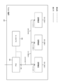
- FIG. 1 is a diagram showing a power storage system 100 according to an embodiment.
- FIG. 2 is a diagram showing a controller 130 according to the embodiment.
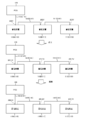
- FIG. 3 is a diagram for explaining the discharge operation according to the embodiment.
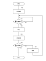
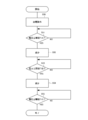
- FIG. 4 is a diagram showing a control method according to the embodiment.
- FIG. 5 is a diagram showing a control method according to the embodiment.
- FIG. 6 is a diagram for explaining the discharge operation according to the first modification.
- FIG. 7 is a diagram showing a control method according to the first modification.
- FIG. 8 is a diagram showing a control method according to the first modification.
- FIG. 9 is a diagram for explaining the discharge operation according to the second modification.
- FIG. 10 is a diagram showing a control method according to the second modification.
- FIG. 11 is a diagram showing a control method according to the second modification.
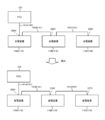
- FIG. 12 is a diagram showing a power storage system 100 according to the third modification.
- the power storage system 100 includes two or more power storage devices 110, a PCS (Power Conditioning System) 120, and a controller 130.
- Each of the two or more power storage devices 110 is connected in parallel to one PCS 120 by wiring 141.
- the power storage device 110 As the power storage device 110, the power storage device 110A, the power storage device 110B, and the power storage device 110C are exemplified.
- the wiring 141A connects the power storage device 110A and the PCS 120
- the wiring 141B connects the power storage device 110A and the power storage device 110B
- the wiring 141C connects the power storage device 110B and the power storage device 110C.
- wiring 141 of either the positive electrode or the negative electrode is illustrated. Therefore, it should be noted that the connection modes of the power storage device 110A, the power storage device 110B, and the power storage device 110C are not in series but in parallel.
- the lengths of the wiring 141 connecting each power storage device 110 and the PCS 120 are different from each other. Specifically, the wiring 141 connecting the power storage device 110C and the PCS 120 is longer than the wiring 141 connecting the power storage device 110B and the PCS 120, and the wiring 141 connecting the power storage device 110B and the PCS 120 is connected to the power storage device 110A. It is longer than the wiring 141 connecting to the PCS 120.
- the power storage device 110 is a device that stores electric power. Specifically, the power storage device 110 may have two or more power storage cells for storing electric power. Two or more storage cells may form a cell string connected in series with each other. The power storage device 110 may have two or more cell strings connected in parallel with each other. The power storage device 110 has a discharge resistance connected to each of the two or more power storage cells, and has a function of suppressing variations in the voltage values of the two or more power storage cells due to discharge from the power storage cells to the discharge resistance (hereinafter,). , Cell balance function). The voltage value of the power storage cell may be made uniform by repeatedly charging or discharging the power storage device 110.
- the power storage device 110 has an interface end 111 that outputs power from the power storage device 110 or inputs power to the power storage device 110.
- the power storage device 110A has an interface end 111A
- the power storage device 110B has an interface end 111B
- the power storage device 110C has an interface end 111C.
- PCS120 is an example of a power conversion device.
- the PCS 120 converts the DC power output from the power storage device 110 into AC power.
- the PCS 120 converts AC power into DC power input to the power storage device 110.
- the PCS120 has a DC / DC converter, an inverter, and the like.
- the controller 130 controls the PCS 120.
- the controller 130 is wirelessly or wiredly connected to the PCS 120.
- the controller 130 is wirelessly or wiredly connected to the sensor 101.
- the sensor 101 is a sensor that detects the voltage of the power storage device 110A having the shortest wiring 141.
- the sensor 101 may be provided on the wiring 141A or may be provided on the power storage device 110A.
- the wireless system may be a system that conforms to standards such as IEEE802.11a / b / g / n, ZigBee, Wi-SUN, and LTE.
- the wired method may be a method conforming to a standard such as IEEE802.3.
- the controller 130 includes a detection unit 131 and a control unit 132.
- the detection unit 131 constitutes a detection unit that detects the voltage of two or more power storage devices 110.
- the detection unit 131 detects the voltage of the power storage device 110A having the shortest wiring 141 among the two or more power storage devices 110.
- the detection unit 131 detects the voltage of the power storage device 110A by the signal received from the sensor 101.
- the sensor 101 constitutes a detection unit for detecting the voltage of two or more power storage devices 110, and the sensor 101 and the detection unit 131 may constitute a detection unit.
- the control unit 132 may include at least one processor. At least one processor may be composed of a single integrated circuit (IC) or may be composed of a plurality of communicably connected circuits (such as integrated circuits and / or discrete circuits).
- IC integrated circuit
- communicably connected circuits such as integrated circuits and / or discrete circuits.
- the control unit 132 controls the discharging operation and the charging operation of the power storage device 110 by controlling the PCS 120.
- the control unit 132 inputs a predetermined discharge current to the PCS 120 so that the difference between the voltages of the two or more power storage devices 110 becomes small when the voltage detected by the detection unit 131 reaches a predetermined voltage.
- the current reduction control for reducing the predetermined charging current output from the PCS 120 is executed.
- the predetermined voltage may include a lower limit voltage used in the discharging operation of two or more power storage devices 110.
- the lower limit voltage may be referred to as the threshold T1.
- the control unit 132 may execute current reduction control for reducing a predetermined discharge current when the voltage detected by the detection unit 131 reaches the lower limit voltage in the discharge operation of two or more power storage devices 110.
- the control unit 132 may execute current reduction control for reducing a predetermined discharge current when the voltage reduced by the discharge operation reaches the lower limit voltage.
- the current reduction control may include a control to make a predetermined discharge current zero, that is, a control to stop the discharge operation of two or more power storage devices 110.
- the control unit 132 may restart the discharge operation with a current smaller than the current before the stop of the discharge operation after a certain period of time has elapsed after stopping the discharge operation of the two or more power storage devices 110.
- the current smaller than the current before the discharge operation is stopped is the discharge operation as a pulsating current generated by the switching control in which the ON / OFF switching speed is sufficiently high (for example, several tens of kHz or more).
- the current may have a longer OFF time than before the stop.
- the current smaller than the current before the stop of the discharge operation may be a current having a smaller time average current than the current before the stop of the discharge operation in the absence of switching control.
- the predetermined voltage may include an upper limit voltage used in the charging operation of two or more power storage devices 110.
- the upper limit voltage may be referred to as a threshold value T2.
- the control unit 132 may execute current reduction control for reducing a predetermined charging current when the voltage detected by the detection unit 131 reaches the upper limit voltage.
- the control unit 132 may execute current reduction control for reducing a predetermined charging current when the voltage increased by the charging operation reaches the upper limit voltage.
- the current reduction control may include a control for reducing the predetermined charging current to zero, that is, a control for stopping the charging operation of two or more power storage devices 110.
- the control unit 132 may restart the charging operation with a current smaller than the current before the stopping of the charging operation after a certain period of time has elapsed after stopping the charging operation of the two or more power storage devices 110.
- a current smaller than the current before the stop of the charging operation is a pulsating current generated by the switching control at which the ON / OFF switching speed is sufficiently high (for example, several tens of kHz or more), and the charging operation is performed.
- the current may have a longer OFF time than before the stop.
- the current smaller than the current before the stop of the charging operation may be a current having a smaller time average current than the current before the stop of the charging operation in the absence of switching control.
- the controller 130 controls the discharge operation of two or more power storage devices 110.
- the controller 130 controls the discharge operation so that the predetermined discharge current input to the PCS 120 becomes the first discharge current (for example, 30 A).
- the output voltage of the power storage device 110A reaches the lower limit voltage.
- the output voltage of the power storage device 110B is stored. Higher than the output voltage of device 110A (eg 202V).
- the output voltage of the power storage device 110C is lowered due to the impedance of the wiring 141B and the wiring 141C, even if the output voltage of the power storage device 110A reaches the lower limit voltage, the output voltage of the power storage device 110C is the power storage device. It is higher than the output voltage of 110A and the power storage device 110B (for example, 203V).
- the controller 130 stops the discharging operation of two or more power storage devices 110.
- the controller 130 keeps the state in which the discharge operation is stopped for a certain period of time.
- the control that continues the state in which the discharge operation is stopped may be referred to as standby control.
- the voltages of the two or more power storage devices 110 are aligned (for example, 201.7V) according to such standby control.
- the controller 130 restarts the discharge operation of two or more power storage devices 110.
- the controller 130 controls the discharge operation so that the predetermined discharge current input to the PCS 120 becomes a second discharge current (for example, 15 A) smaller than the first discharge current (for example, 30 A).
- the voltage of the power storage device 110A reaches 200.2V
- the voltage of the power storage device 110B is 201.2V
- the voltage of the power storage device 110C is 201.7V.
- the difference in voltage between the two or more power storage devices 110 is suppressed as compared with the case shown in the upper part of FIG.
- FIG. 3 illustrates a case where the predetermined discharge current is reduced from the first discharge current to the second discharge current, but the embodiment is not limited to this.
- control may be executed to reduce the predetermined discharge current from the second discharge current to the third discharge current smaller than the second discharge current. That is, control for reducing the predetermined discharge current in two or more steps may be executed.
- step S10 the controller 130 controls the discharge operation of two or more power storage devices 110.
- step S11 the controller 130 determines whether or not the voltage detected by the detection unit 131 is equal to or lower than the lower limit voltage (threshold value T1), that is, whether or not the voltage detected by the detection unit 131 reaches the threshold value T1. judge.
- the controller 130 executes a discharge operation when the voltage does not reach the threshold value T1.
- the controller 130 executes the operation of step S12 when the voltage reaches the threshold value T1.
- step S12 the controller 130 stops the discharging operation of two or more power storage devices 110.
- step S13 the controller 130 continues the state in which the discharge operation is stopped for a certain period of time (standby control).
- step S14 the controller 130 determines whether or not the voltage detected by the detection unit 131 is equal to or lower than the lower limit voltage (threshold value T1), that is, the voltage detected by the detection unit 131 sets the threshold value T1 by standby control for a certain period of time. Determine if it exceeds.
- the controller 130 ends a series of processes when the voltage is equal to or less than the threshold value T1.
- the controller 130 executes the process of step S15 when the voltage is larger than the threshold value T1.
- FIG. 4 assumes a case where the threshold value used in the determination in step S14 is the same as the threshold value T1 used in the determination in step S11, but the embodiment is not limited to this.
- the threshold value used in the determination in step S14 may be larger than the threshold value T1 used in the determination in step S11.
- step S15 the controller 130 restarts the discharging operation of the two or more power storage devices 110.
- the controller 130 may restart the discharge operation with a current smaller than the current before the discharge operation is stopped.
- step S20 the controller 130 controls the charging operation of two or more power storage devices 110.
- step S21 the controller 130 determines whether or not the voltage detected by the detection unit 131 is equal to or higher than the upper limit voltage (threshold value T2), that is, whether or not the voltage detected by the detection unit 131 reaches the threshold value T2. judge.
- the controller 130 executes a charging operation when the voltage does not reach the threshold value T2.
- the controller 130 executes the operation of step S22 when the voltage reaches the threshold value T2.
- step S22 the controller 130 stops the charging operation of two or more power storage devices 110.
- step S23 the controller 130 continues the state in which the charging operation is stopped for a certain period of time (standby control).
- step S24 the controller 130 determines whether or not the voltage detected by the detection unit 131 is equal to or higher than the upper limit voltage (threshold value T2), that is, the voltage detected by the detection unit 131 sets the threshold value T2 by standby control for a certain period of time. Determine if it is below.
- the controller 130 ends a series of processes when the voltage is equal to or higher than the threshold value T2.
- the controller 130 executes the process of step S25 when the voltage is smaller than the threshold value T2.
- FIG. 5 assumes a case where the threshold value used in the determination in step S24 is the same as the threshold value T2 used in the determination in step S21, but the embodiment is not limited to this.
- the threshold value used in the determination in step S24 may be smaller than the threshold value T2 used in the determination in step S21.
- step S25 the controller 130 restarts the charging operation of two or more power storage devices 110.
- the controller 130 may restart the charging operation with a current smaller than the current before the charging operation is stopped.
- the controller 130 executes a current reduction control for reducing a predetermined discharge current or a predetermined charge current when the voltage detected by the detection unit 131 reaches a predetermined voltage.
- a current reduction control for reducing a predetermined discharge current or a predetermined charge current when the voltage detected by the detection unit 131 reaches a predetermined voltage.
- the current reduction control includes a control for reducing a predetermined discharge current or a predetermined charge current without stopping the discharge operation or the charge operation.
- the controller 130 executes a control for gradually reducing a predetermined discharge current or a predetermined charge current in the current reduction control.
- the controller 130 controls the discharge operation of two or more power storage devices 110.
- the controller 130 controls the discharge operation so that the predetermined discharge current input to the PCS 120 becomes the first discharge current (for example, 30 A).
- the output voltage of the power storage device 110A reaches the lower limit voltage.
- the output voltage of the power storage device 110B is stored. Higher than the output voltage of device 110A (eg 220V).
- the output voltage of the power storage device 110C is lowered due to the impedance of the wiring 141B and the wiring 141C, even if the output voltage of the power storage device 110A reaches the lower limit voltage, the output voltage of the power storage device 110C is the power storage device. It is higher than the output voltage of 110A and the power storage device 110B (for example, 230V).
- the controller 130 reduces the predetermined discharge current without stopping the discharge operation.
- the controller 130 controls the discharge operation so that the predetermined discharge current input to the PCS 120 becomes a second discharge current (for example, 27 A) smaller than the first discharge current (for example, 30 A).
- the controller 130 reduces the current at a predetermined ratio (10%) with respect to the first discharge current from the predetermined discharge current.
- the current reduction control by gradually reducing the predetermined discharge current, the influence of the impedance of the wiring 141 on the voltage difference of the power storage device 110 is reduced, so that the power storage device 110 having a relatively high voltage is used.
- the current can be taken out. Therefore, it is possible to suppress the difference in voltage between two or more power storage devices 110. Further, an efficient discharge operation can be realized as a whole of the two or more power storage devices 110.
- FIG. 6 illustrates a case where the predetermined discharge current is reduced from the first discharge current to the second discharge current, but the modification 1 is not limited to this.
- the control of reducing the current at a predetermined ratio (10%) with respect to the first discharge current from the predetermined discharge current may be repeated.
- the decrease of the predetermined discharge current may be repeated until the predetermined discharge current becomes zero.
- step S30 the controller 130 controls the discharge operation of two or more power storage devices 110.
- step S31 the controller 130 determines whether or not the voltage detected by the detection unit 131 is equal to or lower than the lower limit voltage (threshold value T1), that is, whether or not the voltage detected by the detection unit 131 reaches the threshold value T1. judge.
- the controller 130 executes a discharge operation when the voltage does not reach the threshold value T1.
- the controller 130 executes the operation of step S32 when the voltage reaches the threshold value T1.
- step S32 the controller 130 reduces the predetermined discharge current.
- the reduction rate of the predetermined discharge current is 10%.
- the controller 130 continues the discharge operation for a certain period (for example, 10 seconds).
- step S33 the controller 130 determines whether or not the predetermined discharge current is zero.
- the controller 130 ends a series of processes when the predetermined discharge current is zero. If the predetermined discharge current is not zero, the controller 130 returns to the process of step S32.
- step S40 the controller 130 controls the charging operation of two or more power storage devices 110.
- step S41 the controller 130 determines whether or not the voltage detected by the detection unit 131 is equal to or higher than the upper limit voltage (threshold value T2), that is, whether or not the voltage detected by the detection unit 131 reaches the threshold value T2. judge.
- the controller 130 executes a charging operation when the voltage does not reach the threshold value T2.
- the controller 130 executes the operation of step S42 when the voltage reaches the threshold value T2.
- step S42 the controller 130 reduces the predetermined charging current.
- the reduction rate of the predetermined charging current is 10%.
- the controller 130 continues the charging operation for a certain period (for example, 10 seconds).
- step S43 the controller 130 determines whether or not the predetermined charging current is zero.
- the controller 130 ends a series of processes when the predetermined charging current is zero. If the predetermined charging current is not zero, the controller 130 returns to the process of step S42.
- the controller 130 executes a control for gradually reducing a predetermined discharge current or a predetermined charge current in the current reduction control. According to such a configuration, it is possible to suppress the difference in voltage between the two or more power storage devices 110 at the time when the discharge operation or the charge operation is completed, as in the embodiment. Further, an efficient discharge operation or charge operation can be realized as a whole of the two or more power storage devices 110.
- the controller 130 executes a control for gradually reducing the predetermined discharge current or the predetermined charge current when the voltage detected by the detection unit 131 reaches the lower limit voltage or the upper limit voltage.
- the predetermined voltage is the lower limit voltage or the upper limit voltage.
- the controller 130 executes a control for gradually reducing the predetermined discharge current when the voltage detected by the detection unit 131 reaches a predetermined voltage larger than the lower limit voltage.
- the controller 130 executes a control for gradually reducing the predetermined charging current when the voltage detected by the detection unit 131 reaches a predetermined voltage smaller than the upper limit voltage.
- the controller 130 controls the discharge operation of two or more power storage devices 110.
- the controller 130 controls the discharge operation so that the predetermined discharge current input to the PCS 120 becomes the first discharge current (for example, 30 A).
- the output voltage of the power storage device 110A reaches the first predetermined voltage (210V in the upper part of FIG. 9), which is larger than the lower limit voltage, will be described.
- the output voltage of the power storage device 110B drops due to the impedance of the wiring 141B, even if the output voltage of the power storage device 110A reaches the first predetermined voltage, the output voltage of the power storage device 110B remains.
- Higher than the output voltage of the power storage device 110A for example, 212V).
- the output voltage of the power storage device 110C is lowered due to the impedance of the wiring 141B and the wiring 141C, even if the output voltage of the power storage device 110A reaches the first predetermined voltage, the output voltage of the power storage device 110C is still high. It is higher than the output voltage of the power storage device 110A and the power storage device 110B (for example, 213V).
- the controller 130 reduces the predetermined discharge current without stopping the discharge operation.
- the controller 130 controls the discharge operation so that the predetermined discharge current input to the PCS 120 becomes a second discharge current (for example, 20 A) smaller than the first discharge current (for example, 30 A).
- the controller 130 reduces the current at a predetermined ratio (33%) with respect to the first discharge current from the predetermined discharge current.
- the output voltage of the power storage device 110A reaches a second predetermined voltage (205V in the middle stage of FIG. 9), which is larger than the lower limit voltage, will be described.
- the influence of the impedance of the wiring 141 is smaller than that in the upper part of FIG. 9, so that the difference between the voltages of the two or more power storage devices 110 is reduced.
- the voltage of the power storage device 110B is 206.4V
- the voltage of the power storage device 110C is 207.1V.
- the controller 130 further reduces the predetermined discharge current without stopping the discharge operation.
- the controller 130 controls the discharge operation so that the predetermined discharge current input to the PCS 120 becomes a third discharge current (for example, 10 A) smaller than the second discharge current (for example, 20 A).
- the controller 130 further reduces the current at a predetermined ratio (33%) with respect to the first discharge current from the predetermined discharge current.
- the output voltage of the power storage device 110A reaches a third predetermined voltage (202V in the middle stage of FIG. 9), which is larger than the lower limit voltage, will be described.
- a third predetermined voltage 202V in the middle stage of FIG. 9
- the difference between the voltages of the two or more power storage devices 110 is further reduced.
- the voltage of the power storage device 110B is 202.6V
- the voltage of the power storage device 110C is 202.9V.
- the current reduction control by gradually reducing the predetermined discharge current, the influence of the impedance of the wiring 141 on the voltage difference of the power storage device 110 becomes small, and the difference between the voltages of two or more power storage devices 110 can be reduced. It can be suppressed. Further, an efficient discharge operation can be realized as a whole of the two or more power storage devices 110.
- FIG. 9 illustrates a case where the predetermined discharge current is reduced in three steps by using three predetermined voltages, but the modification 2 is not limited to this.
- the predetermined discharge current may be reduced in two steps using two predetermined voltages.
- the predetermined discharge current may be reduced in four or more steps by using four or more predetermined voltages.
- the smallest predetermined voltage may be the lower limit voltage.
- step S50 the controller 130 controls the discharge operation of two or more power storage devices 110.
- step S51 the controller 130 determines whether or not the voltage detected by the detection unit 131 is equal to or less than the threshold value T1A (for example, 210V shown in the upper part of FIG. 9), that is, the voltage detected by the detection unit 131 is the threshold value T1A. Is determined.
- the controller 130 executes a discharge operation when the voltage does not reach the threshold value T1A.
- the controller 130 executes the operation of step S52 when the voltage reaches the threshold value T1A.
- step S52 the controller 130 reduces the predetermined discharge current.
- the reduction rate of the predetermined discharge current is 33%.
- step S53 the controller 130 is detected by the detection unit 131 whether or not the voltage detected by the detection unit 131 is equal to or less than the threshold T1B ( ⁇ threshold T1A (for example, 205V shown in the middle of FIG. 9)). It is determined whether or not the applied voltage has reached the threshold value T1B. The controller 130 executes a discharge operation when the voltage does not reach the threshold value T1B. The controller 130 executes the operation of step S54 when the voltage reaches the threshold value T1B.
- the threshold T1B ⁇ threshold T1A (for example, 205V shown in the middle of FIG. 9)
- step S54 the controller 130 reduces the predetermined discharge current.
- the reduction rate of the predetermined discharge current is 33%.
- step S55 the controller 130 determines whether or not the voltage detected by the detection unit 131 is equal to or less than the threshold value T1C (for example, the lower limit voltage ( ⁇ threshold value T1B)), that is, the voltage detected by the detection unit 131 becomes the threshold value T1C.
- the controller 130 executes a discharge operation when the voltage does not reach the threshold value T1C.
- the controller 130 ends a series of processes when the voltage reaches the threshold value T1C. do. Secondly, the charging operation will be described with reference to FIG.
- step S60 the controller 130 controls the charging operation of two or more power storage devices 110.
- step S61 the controller 130 determines whether or not the voltage detected by the detection unit 131 is equal to or higher than the threshold value T2A, that is, whether or not the voltage detected by the detection unit 131 reaches the threshold value T2A.
- the controller 130 executes a charging operation when the voltage does not reach the threshold value T2A.
- the controller 130 executes the operation of step S62 when the voltage reaches the threshold value T2A.
- step S62 the controller 130 reduces the predetermined charging current.
- the reduction rate of the predetermined charging current is 33%.
- step S63 the controller 130 determines whether or not the voltage detected by the detection unit 131 is equal to or higher than the threshold value T2B (> threshold value T2A), that is, whether or not the voltage detected by the detection unit 131 reaches the threshold value T2B. To judge. The controller 130 executes a charging operation when the voltage does not reach the threshold value T2B. The controller 130 executes the operation of step S64 when the voltage reaches the threshold value T2B.
- step S64 the controller 130 reduces the predetermined charging current.
- the reduction rate of the predetermined charging current is 33%.
- step S65 the controller 130 determines whether or not the voltage detected by the detection unit 131 is equal to or higher than the threshold value T2C (for example, the upper limit voltage (> threshold value T2B)), that is, the voltage detected by the detection unit 131 is the threshold value T2C. Is determined.
- the controller 130 executes a charging operation when the voltage does not reach the threshold value T2C.
- the controller 130 ends a series of processes.
- the mode in which the power storage device 110B and the power storage device 110C are not directly connected to the PCS 120 has been described.
- the third modification not only the power storage device 110A but also the power storage device 110B and the power storage device 110C may be directly connected to the PCS 120.
- the power storage device 110A is connected to the PCS 120 by the wiring 142A and the wiring 142E.
- the power storage device 110B is connected to the PCS 120 by the wiring 142B, the wiring 142D, and the wiring 142E.
- the power storage device 110C is connected to the PCS 120 by the wiring 142C, the wiring 142D, and the wiring 142E.
- the point that the power storage device 110A, the power storage device 110B, and the power storage device 110C are connected in parallel to the PCS 120 by the wiring 142 is the same as that of the embodiment.
- the lengths of the wiring 142 connecting each power storage device 110 and the PCS 120 are different from each other as in the embodiment. Specifically, the wiring 142 connecting the power storage device 110C and the PCS 120 is longer than the wiring 142 connecting the power storage device 110B and the PCS 120, and the wiring 142 connecting the power storage device 110B and the PCS 120 is the power storage device 110A. It is longer than the wiring that connects to the PCS120.
- the controller 130 detects the voltage of the power storage device 110A having the shortest wiring 141 among the two or more power storage devices 110.
- the sensor 101 may be provided on the wiring 142A or may be provided on the power storage device 110A.
- the lower limit voltage may be the discharge end at which the power storage device 110 is allowed to be discharged.
- the embodiment is not limited to this.
- the lower limit voltage may be a voltage defined to secure a BCP (Business Continuity Planning) power supply.
- the upper limit voltage may be the charging end at which charging of the power storage device 110 is permitted.
- the embodiment is not limited to this.
- the upper limit voltage may be a voltage defined to secure a surplus charging capacity in a negawatt transaction or the like.
- the case where the voltage detected by the detection unit 131 is the voltage of the power storage device 110A in which the wiring 141 or the wiring 142 is the shortest is illustrated. That is, the case where the material and the thickness of the wiring 141 or the wiring 142 are the same has been illustrated.
- the embodiment is not limited to this. For example, it may be assumed that the material and thickness of the wiring 141 or 142 are partially different. In such a case, the voltage detected by the detection unit 131 may be the power storage device 110 having the smallest impedance of the wiring 141 or the wiring 142. For example, in FIG.
- the materials and thicknesses of the wiring 142A, the wiring 142B, the wiring 142C, the wiring 142D, and the wiring 142E may be different.
- the sensor 101 may be provided on the wiring 142B or may be provided on the power storage device 110B.
Landscapes
- Engineering & Computer Science (AREA)
- Chemical & Material Sciences (AREA)
- Chemical Kinetics & Catalysis (AREA)
- Electrochemistry (AREA)
- General Chemical & Material Sciences (AREA)
- Power Engineering (AREA)
- Microelectronics & Electronic Packaging (AREA)
- Manufacturing & Machinery (AREA)
- Charge And Discharge Circuits For Batteries Or The Like (AREA)
- Secondary Cells (AREA)
Abstract
Description
(蓄電システム)
以下において、実施形態に係る蓄電システムについて説明する。図1に示すように、蓄電システム100は、2以上の蓄電装置110と、PCS(Power Conditioning System)120と、コントローラ130と、を有する。2以上の蓄電装置110のそれぞれは、配線141によって1つのPCS120に対して並列で接続される。
以下において、実施形態に係るコントローラについて説明する。図2に示すように、コントローラ130は、検出部131と、制御部132と、を有する。
以下において、実施形態に係る電流減少制御について説明する。ここでは、放電動作における電流減少制御を例示する。図3では、下限電圧は200Vである。
以下において、実施形態に係る制御方法について説明する。
実施形態では、コントローラ130は、検出部131によって検出される電圧が所定電圧に達した場合に、所定放電電流又は所定充電電流を減少する電流減少制御を実行する。このような構成によれば、蓄電装置110の電圧が所定電圧に達した時点において、2以上の蓄電装置110の電圧の差異を抑制することができる。さらには、2以上の蓄電装置110の全体として効率的な放電動作又は充電動作を実現することができる。
以下において、実施形態の変更例1について説明する。以下においては、実施形態に対する相違点について主として説明する。
以下において、変更例1に係る電流減少制御について説明する。ここでは、放電動作における電流減少制御を例示する。図6では、下限電圧は200Vである。
以下において、変更例1に係る制御方法について説明する。
変更例1では、コントローラ130は、電流減少制御において、所定放電電流又は所定充電電流を徐々に減少する制御を実行する。このような構成によれば、実施形態と同様に、放電動作又は充電動作の完了時点において、2以上の蓄電装置110の電圧の差異を抑制することができる。さらには、2以上の蓄電装置110の全体として効率的な放電動作又は充電動作を実現することができる。
以下において、実施形態の変更例2について説明する。以下においては、変更例1に対する相違点について主として説明する。
以下において、変更例2に係る電流減少制御について説明する。ここでは、放電動作における電流減少制御を例示する。図9では、下限電圧は200Vである。
以下において、変更例2に係る制御方法について説明する。
第2に、充電動作について、図11を参照しながら説明する。
以下において、実施形態の変更例3について説明する。以下においては、実施形態に対する相違点について主として説明する。
本発明は上述した実施形態によって説明したが、この開示の一部をなす論述及び図面は、この発明を限定するものであると理解すべきではない。この開示から当業者には様々な代替実施形態、実施例及び運用技術が明らかとなろう。
Claims (8)
- 1つの電力変換装置に対して2以上の蓄電装置のそれぞれが配線によって並列で接続された蓄電システムであって、
前記2以上の蓄電装置の電圧を検出する検出部と、
前記検出部によって検出される電圧が所定電圧に達した場合に、前記2以上の蓄電装置の電圧の差異が小さくなるように、前記電力変換装置に入力される所定放電電流又は前記電力変換装置から出力される所定充電電流を減少する電流減少制御を実行する制御部と、を備える蓄電システム。 - 前記検出部は、前記2以上の蓄電装置の中で、前記配線のインピーダンスが最も小さい蓄電装置の電圧を検出する、請求項1に記載の蓄電システム。
- 前記所定電圧は、前記2以上の蓄電装置の放電動作で用いる下限電圧を含み、
前記制御部は、前記2以上の蓄電装置の放電動作において、前記検出部によって検出される電圧が前記下限電圧に達した場合に、前記所定放電電流を減少する前記電流減少制御を実行する、請求項1又は請求項2に記載の蓄電システム。 - 前記所定電圧は、前記2以上の蓄電装置の充電動作で用いる上限電圧を含み、
前記制御部は、前記2以上の蓄電装置の充電動作において、前記検出部によって検出される電圧が前記上限電圧に達した場合に、前記所定充電電流を減少する前記電流減少制御を実行する、請求項1又は請求項2に記載の蓄電システム。 - 前記電流減少制御は、前記2以上の蓄電装置の放電動作又は前記2以上の蓄電装置の充電動作を停止する制御を含む、請求項1乃至請求項4のいずれか1項に記載の蓄電システム。
- 前記制御部は、
前記2以上の蓄電装置の放電動作を停止してから一定期間が経過した後において、前記放電動作の停止前の電流よりも小さい電流で前記放電動作を再開し、或いは、
前記2以上の蓄電装置の充電動作を停止してから一定期間が経過した後において、前記充電動作の停止前の電流よりも小さい電流で前記充電動作を再開する、請求項5に記載の蓄電システム。 - 前記制御部は、前記電流減少制御において、前記所定放電電流又は前記所定充電電流を徐々に減少する制御を実行する、請求項1乃至請求項4のいずれか1項に記載の蓄電システム。
- 1つの電力変換装置に対して2以上の蓄電装置のそれぞれが配線によって並列で接続された蓄電システムで用いる制御方法あって、
前記2以上の蓄電装置の電圧を検出するステップAと、
前記ステップAで検出される電圧が所定電圧に達した場合に、前記2以上の蓄電装置の電圧の差異が小さくなるように、前記電力変換装置に入力される所定放電電流又は前記電力変換装置から出力される所定充電電流を減少する電流減少制御を実行するステップBと、を備える、制御方法。
Priority Applications (3)
| Application Number | Priority Date | Filing Date | Title |
|---|---|---|---|
| EP21797320.5A EP4145587A4 (en) | 2020-04-27 | 2021-04-06 | ELECTRICITY STORAGE SYSTEM AND CONTROL METHOD |
| JP2022517582A JP7498265B2 (ja) | 2020-04-27 | 2021-04-06 | 蓄電システム及び制御方法 |
| US17/997,118 US20230170721A1 (en) | 2020-04-27 | 2021-04-06 | Power storage system and control method |
Applications Claiming Priority (2)
| Application Number | Priority Date | Filing Date | Title |
|---|---|---|---|
| JP2020-078203 | 2020-04-27 | ||
| JP2020078203 | 2020-04-27 |
Publications (1)
| Publication Number | Publication Date |
|---|---|
| WO2021220733A1 true WO2021220733A1 (ja) | 2021-11-04 |
Family
ID=78332357
Family Applications (1)
| Application Number | Title | Priority Date | Filing Date |
|---|---|---|---|
| PCT/JP2021/014632 Ceased WO2021220733A1 (ja) | 2020-04-27 | 2021-04-06 | 蓄電システム及び制御方法 |
Country Status (4)
| Country | Link |
|---|---|
| US (1) | US20230170721A1 (ja) |
| EP (1) | EP4145587A4 (ja) |
| JP (1) | JP7498265B2 (ja) |
| WO (1) | WO2021220733A1 (ja) |
Families Citing this family (1)
| Publication number | Priority date | Publication date | Assignee | Title |
|---|---|---|---|---|
| US20230006451A1 (en) * | 2019-12-13 | 2023-01-05 | Kyocera Corporation | Electricity storage device and electricity storage method |
Citations (2)
| Publication number | Priority date | Publication date | Assignee | Title |
|---|---|---|---|---|
| WO2012049910A1 (ja) * | 2010-10-15 | 2012-04-19 | 三洋電機株式会社 | 電力供給システムの出力回路 |
| WO2013121849A1 (ja) | 2012-02-16 | 2013-08-22 | 日本電気株式会社 | 調整装置、組電池装置および調整方法 |
Family Cites Families (5)
| Publication number | Priority date | Publication date | Assignee | Title |
|---|---|---|---|---|
| TWI231081B (en) * | 2002-12-23 | 2005-04-11 | O2Micro Int Ltd | Charging circuit for parallel charging in multiple battery systems |
| US8823323B2 (en) * | 2009-04-16 | 2014-09-02 | Valence Technology, Inc. | Batteries, battery systems, battery submodules, battery operational methods, battery system operational methods, battery charging methods, and battery system charging methods |
| JP5821619B2 (ja) * | 2011-12-26 | 2015-11-24 | ソニー株式会社 | 電力貯蔵装置、電力システムおよび電動車両 |
| JP6225986B2 (ja) * | 2013-03-28 | 2017-11-08 | ソニー株式会社 | 蓄電装置および蓄電装置の制御方法 |
| KR101631065B1 (ko) * | 2013-12-03 | 2016-06-16 | 삼성에스디아이 주식회사 | 배터리 시스템 및 배터리 연결방법 |
-
2021
- 2021-04-06 US US17/997,118 patent/US20230170721A1/en active Pending
- 2021-04-06 JP JP2022517582A patent/JP7498265B2/ja active Active
- 2021-04-06 WO PCT/JP2021/014632 patent/WO2021220733A1/ja not_active Ceased
- 2021-04-06 EP EP21797320.5A patent/EP4145587A4/en not_active Withdrawn
Patent Citations (2)
| Publication number | Priority date | Publication date | Assignee | Title |
|---|---|---|---|---|
| WO2012049910A1 (ja) * | 2010-10-15 | 2012-04-19 | 三洋電機株式会社 | 電力供給システムの出力回路 |
| WO2013121849A1 (ja) | 2012-02-16 | 2013-08-22 | 日本電気株式会社 | 調整装置、組電池装置および調整方法 |
Non-Patent Citations (1)
| Title |
|---|
| See also references of EP4145587A4 |
Also Published As
| Publication number | Publication date |
|---|---|
| EP4145587A1 (en) | 2023-03-08 |
| JPWO2021220733A1 (ja) | 2021-11-04 |
| JP7498265B2 (ja) | 2024-06-11 |
| US20230170721A1 (en) | 2023-06-01 |
| EP4145587A4 (en) | 2024-06-19 |
Similar Documents
| Publication | Publication Date | Title |
|---|---|---|
| TWI448046B (zh) | Uninterruptible power supply unit | |
| JPH11127573A (ja) | Dc/dcコンバータの並列運転装置 | |
| US20180019684A1 (en) | Power converter | |
| JP6648614B2 (ja) | 蓄電装置 | |
| JP2014180214A (ja) | 電力変換システム | |
| JP2004187496A (ja) | 多数のバッテリの充電方法及び装置 | |
| US10069438B2 (en) | Power converter with capacitor voltage balancing | |
| JP2007135373A (ja) | コンバータ装置およびその出力制御方法 | |
| EP1938444A2 (en) | Feed-forward circuit for adjustable output voltage controller circuits | |
| KR20070086054A (ko) | 전력 변환기, 모바일 장치 및 무선 송신 시스템 | |
| JP7498265B2 (ja) | 蓄電システム及び制御方法 | |
| CN114567035A (zh) | 一种电池供电装置及系统 | |
| TW202304110A (zh) | 儲能裝置及其電源供應方法 | |
| TWI519032B (zh) | 充電方法及其適用之充電系統 | |
| JP2000323365A (ja) | 直流給電装置 | |
| KR102675248B1 (ko) | 전력 공급 시스템 및 전력 공급 시스템의 제어 방법 | |
| JP2002176782A (ja) | 無停電電源装置 | |
| JP4349773B2 (ja) | バッテリ充電方法及び該充電方法を実施するバックアップ電源装置 | |
| JP3202651B2 (ja) | 入力電力制御式充電方式 | |
| JP2014197961A (ja) | 充電装置 | |
| JP3926634B2 (ja) | 停復電検出装置 | |
| JP2000245074A (ja) | 蓄電池の容量低下防止方法 | |
| JP2017108558A (ja) | 直流電源システム | |
| WO2020105141A1 (ja) | 電力供給システム | |
| WO2016031098A1 (ja) | 電源装置 |
Legal Events
| Date | Code | Title | Description |
|---|---|---|---|
| 121 | Ep: the epo has been informed by wipo that ep was designated in this application |
Ref document number: 21797320 Country of ref document: EP Kind code of ref document: A1 |
|
| ENP | Entry into the national phase |
Ref document number: 2022517582 Country of ref document: JP Kind code of ref document: A |
|
| NENP | Non-entry into the national phase |
Ref country code: DE |
|
| ENP | Entry into the national phase |
Ref document number: 2021797320 Country of ref document: EP Effective date: 20221128 |
|
| WWW | Wipo information: withdrawn in national office |
Ref document number: 2021797320 Country of ref document: EP |