WO2021220848A1 - 車両用灯具 - Google Patents
車両用灯具 Download PDFInfo
- Publication number
- WO2021220848A1 WO2021220848A1 PCT/JP2021/015739 JP2021015739W WO2021220848A1 WO 2021220848 A1 WO2021220848 A1 WO 2021220848A1 JP 2021015739 W JP2021015739 W JP 2021015739W WO 2021220848 A1 WO2021220848 A1 WO 2021220848A1
- Authority
- WO
- WIPO (PCT)
- Prior art keywords
- silicone resin
- fog
- ppm
- small molecule
- lamp
- Prior art date
- Legal status (The legal status is an assumption and is not a legal conclusion. Google has not performed a legal analysis and makes no representation as to the accuracy of the status listed.)
- Ceased
Links
Images


Classifications
-
- F—MECHANICAL ENGINEERING; LIGHTING; HEATING; WEAPONS; BLASTING
- F21—LIGHTING
- F21S—NON-PORTABLE LIGHTING DEVICES; SYSTEMS THEREOF; VEHICLE LIGHTING DEVICES SPECIALLY ADAPTED FOR VEHICLE EXTERIORS
- F21S45/00—Arrangements within vehicle lighting devices specially adapted for vehicle exteriors, for purposes other than emission or distribution of light
-
- B—PERFORMING OPERATIONS; TRANSPORTING
- B60—VEHICLES IN GENERAL
- B60Q—ARRANGEMENT OF SIGNALLING OR LIGHTING DEVICES, THE MOUNTING OR SUPPORTING THEREOF OR CIRCUITS THEREFOR, FOR VEHICLES IN GENERAL
- B60Q1/00—Arrangement of optical signalling or lighting devices, the mounting or supporting thereof or circuits therefor
- B60Q1/02—Arrangement of optical signalling or lighting devices, the mounting or supporting thereof or circuits therefor the devices being primarily intended to illuminate the way ahead or to illuminate other areas of way or environments
- B60Q1/04—Arrangement of optical signalling or lighting devices, the mounting or supporting thereof or circuits therefor the devices being primarily intended to illuminate the way ahead or to illuminate other areas of way or environments the devices being headlights
-
- F—MECHANICAL ENGINEERING; LIGHTING; HEATING; WEAPONS; BLASTING
- F21—LIGHTING
- F21S—NON-PORTABLE LIGHTING DEVICES; SYSTEMS THEREOF; VEHICLE LIGHTING DEVICES SPECIALLY ADAPTED FOR VEHICLE EXTERIORS
- F21S41/00—Illuminating devices specially adapted for vehicle exteriors, e.g. headlamps
- F21S41/20—Illuminating devices specially adapted for vehicle exteriors, e.g. headlamps characterised by refractors, transparent cover plates, light guides or filters
- F21S41/28—Cover glass
-
- F—MECHANICAL ENGINEERING; LIGHTING; HEATING; WEAPONS; BLASTING
- F21—LIGHTING
- F21S—NON-PORTABLE LIGHTING DEVICES; SYSTEMS THEREOF; VEHICLE LIGHTING DEVICES SPECIALLY ADAPTED FOR VEHICLE EXTERIORS
- F21S41/00—Illuminating devices specially adapted for vehicle exteriors, e.g. headlamps
- F21S41/20—Illuminating devices specially adapted for vehicle exteriors, e.g. headlamps characterised by refractors, transparent cover plates, light guides or filters
- F21S41/285—Refractors, transparent cover plates, light guides or filters not provided in groups F21S41/24 - F21S41/2805
-
- F—MECHANICAL ENGINEERING; LIGHTING; HEATING; WEAPONS; BLASTING
- F21—LIGHTING
- F21S—NON-PORTABLE LIGHTING DEVICES; SYSTEMS THEREOF; VEHICLE LIGHTING DEVICES SPECIALLY ADAPTED FOR VEHICLE EXTERIORS
- F21S41/00—Illuminating devices specially adapted for vehicle exteriors, e.g. headlamps
- F21S41/30—Illuminating devices specially adapted for vehicle exteriors, e.g. headlamps characterised by reflectors
- F21S41/32—Optical layout thereof
- F21S41/33—Multi-surface reflectors, e.g. reflectors with facets or reflectors with portions of different curvature
- F21S41/334—Multi-surface reflectors, e.g. reflectors with facets or reflectors with portions of different curvature the reflector consisting of patch like sectors
- F21S41/336—Multi-surface reflectors, e.g. reflectors with facets or reflectors with portions of different curvature the reflector consisting of patch like sectors with discontinuity at the junction between adjacent areas
-
- F—MECHANICAL ENGINEERING; LIGHTING; HEATING; WEAPONS; BLASTING
- F21—LIGHTING
- F21S—NON-PORTABLE LIGHTING DEVICES; SYSTEMS THEREOF; VEHICLE LIGHTING DEVICES SPECIALLY ADAPTED FOR VEHICLE EXTERIORS
- F21S41/00—Illuminating devices specially adapted for vehicle exteriors, e.g. headlamps
- F21S41/30—Illuminating devices specially adapted for vehicle exteriors, e.g. headlamps characterised by reflectors
- F21S41/32—Optical layout thereof
- F21S41/36—Combinations of two or more separate reflectors
-
- F—MECHANICAL ENGINEERING; LIGHTING; HEATING; WEAPONS; BLASTING
- F21—LIGHTING
- F21S—NON-PORTABLE LIGHTING DEVICES; SYSTEMS THEREOF; VEHICLE LIGHTING DEVICES SPECIALLY ADAPTED FOR VEHICLE EXTERIORS
- F21S41/00—Illuminating devices specially adapted for vehicle exteriors, e.g. headlamps
- F21S41/60—Illuminating devices specially adapted for vehicle exteriors, e.g. headlamps characterised by a variable light distribution
- F21S41/67—Illuminating devices specially adapted for vehicle exteriors, e.g. headlamps characterised by a variable light distribution by acting on reflectors
- F21S41/675—Illuminating devices specially adapted for vehicle exteriors, e.g. headlamps characterised by a variable light distribution by acting on reflectors by moving reflectors
-
- G—PHYSICS
- G02—OPTICS
- G02B—OPTICAL ELEMENTS, SYSTEMS OR APPARATUS
- G02B1/00—Optical elements characterised by the material of which they are made; Optical coatings for optical elements
- G02B1/10—Optical coatings produced by application to, or surface treatment of, optical elements
- G02B1/18—Coatings for keeping optical surfaces clean, e.g. hydrophobic or photo-catalytic films
-
- B—PERFORMING OPERATIONS; TRANSPORTING
- B29—WORKING OF PLASTICS; WORKING OF SUBSTANCES IN A PLASTIC STATE IN GENERAL
- B29C—SHAPING OR JOINING OF PLASTICS; SHAPING OF MATERIAL IN A PLASTIC STATE, NOT OTHERWISE PROVIDED FOR; AFTER-TREATMENT OF THE SHAPED PRODUCTS, e.g. REPAIRING
- B29C45/00—Injection moulding, i.e. forcing the required volume of moulding material through a nozzle into a closed mould; Apparatus therefor
- B29C45/0001—Injection moulding, i.e. forcing the required volume of moulding material through a nozzle into a closed mould; Apparatus therefor characterised by the choice of material
-
- B—PERFORMING OPERATIONS; TRANSPORTING
- B29—WORKING OF PLASTICS; WORKING OF SUBSTANCES IN A PLASTIC STATE IN GENERAL
- B29K—INDEXING SCHEME ASSOCIATED WITH SUBCLASSES B29B, B29C OR B29D, RELATING TO MOULDING MATERIALS OR TO MATERIALS FOR MOULDS, REINFORCEMENTS, FILLERS OR PREFORMED PARTS, e.g. INSERTS
- B29K2083/00—Use of polymers having silicon, with or without sulfur, nitrogen, oxygen, or carbon only, in the main chain, as moulding material
-
- B—PERFORMING OPERATIONS; TRANSPORTING
- B29—WORKING OF PLASTICS; WORKING OF SUBSTANCES IN A PLASTIC STATE IN GENERAL
- B29K—INDEXING SCHEME ASSOCIATED WITH SUBCLASSES B29B, B29C OR B29D, RELATING TO MOULDING MATERIALS OR TO MATERIALS FOR MOULDS, REINFORCEMENTS, FILLERS OR PREFORMED PARTS, e.g. INSERTS
- B29K2995/00—Properties of moulding materials, reinforcements, fillers, preformed parts or moulds
- B29K2995/0018—Properties of moulding materials, reinforcements, fillers, preformed parts or moulds having particular optical properties, e.g. fluorescent or phosphorescent
- B29K2995/0026—Transparent
-
- B—PERFORMING OPERATIONS; TRANSPORTING
- B29—WORKING OF PLASTICS; WORKING OF SUBSTANCES IN A PLASTIC STATE IN GENERAL
- B29K—INDEXING SCHEME ASSOCIATED WITH SUBCLASSES B29B, B29C OR B29D, RELATING TO MOULDING MATERIALS OR TO MATERIALS FOR MOULDS, REINFORCEMENTS, FILLERS OR PREFORMED PARTS, e.g. INSERTS
- B29K2995/00—Properties of moulding materials, reinforcements, fillers, preformed parts or moulds
- B29K2995/0037—Other properties
-
- B—PERFORMING OPERATIONS; TRANSPORTING
- B29—WORKING OF PLASTICS; WORKING OF SUBSTANCES IN A PLASTIC STATE IN GENERAL
- B29L—INDEXING SCHEME ASSOCIATED WITH SUBCLASS B29C, RELATING TO PARTICULAR ARTICLES
- B29L2011/00—Optical elements, e.g. lenses, prisms
- B29L2011/0016—Lenses
-
- B—PERFORMING OPERATIONS; TRANSPORTING
- B29—WORKING OF PLASTICS; WORKING OF SUBSTANCES IN A PLASTIC STATE IN GENERAL
- B29L—INDEXING SCHEME ASSOCIATED WITH SUBCLASS B29C, RELATING TO PARTICULAR ARTICLES
- B29L2031/00—Other particular articles
- B29L2031/30—Vehicles, e.g. ships or aircraft, or body parts thereof
-
- F—MECHANICAL ENGINEERING; LIGHTING; HEATING; WEAPONS; BLASTING
- F21—LIGHTING
- F21S—NON-PORTABLE LIGHTING DEVICES; SYSTEMS THEREOF; VEHICLE LIGHTING DEVICES SPECIALLY ADAPTED FOR VEHICLE EXTERIORS
- F21S41/00—Illuminating devices specially adapted for vehicle exteriors, e.g. headlamps
- F21S41/10—Illuminating devices specially adapted for vehicle exteriors, e.g. headlamps characterised by the light source
- F21S41/14—Illuminating devices specially adapted for vehicle exteriors, e.g. headlamps characterised by the light source characterised by the type of light source
- F21S41/141—Light emitting diodes [LED]
- F21S41/147—Light emitting diodes [LED] the main emission direction of the LED being angled to the optical axis of the illuminating device
- F21S41/148—Light emitting diodes [LED] the main emission direction of the LED being angled to the optical axis of the illuminating device the main emission direction of the LED being perpendicular to the optical axis
-
- F—MECHANICAL ENGINEERING; LIGHTING; HEATING; WEAPONS; BLASTING
- F21—LIGHTING
- F21S—NON-PORTABLE LIGHTING DEVICES; SYSTEMS THEREOF; VEHICLE LIGHTING DEVICES SPECIALLY ADAPTED FOR VEHICLE EXTERIORS
- F21S41/00—Illuminating devices specially adapted for vehicle exteriors, e.g. headlamps
- F21S41/20—Illuminating devices specially adapted for vehicle exteriors, e.g. headlamps characterised by refractors, transparent cover plates, light guides or filters
- F21S41/25—Projection lenses
- F21S41/255—Lenses with a front view of circular or truncated circular outline
Definitions
- the present disclosure relates to vehicle lighting equipment, and more particularly to vehicle lighting equipment having an anti-fog film on the inner surface of the front cover.
- Silicone resin is known to release cyclic low molecular weight siloxane (hereinafter, simply referred to as low molecular weight siloxane) as outgas.
- This cyclic small molecule siloxane is a residue of a silicone resin raw material that remains unreacted during silicone resin molding.
- reducing the residual amount of small molecule siloxanes D3 to D10 is an index of the quality standard of silicone resin.
- a low molecular weight siloxane reduction type (low siloxane control grade) silicone resin in which the low molecular weight siloxane content of D3 to D10 is reduced to 300 ppm or less is generally used.
- This disclosure has been made in view of such circumstances, and an object of the present disclosure is to prevent deterioration of anti-fog performance in vehicle lamps using silicone resin parts.
- the vehicle lamp according to one aspect of the present invention defines a lamp body having an opening in the irradiation direction and a lamp chamber covering the opening, and has a synthetic resin as a main component on the inner surface.
- a front cover provided with an antifogging film, a light source arranged in the lamp chamber, and a silicone resin component arranged in the lamp chamber are provided, and the content of cyclic low molecular weight siloxane of D3 to D20 in the silicone resin component. Is 0 to 300 ppm in terms of mass.
- the lens is provided in the lamp chamber and at least one of the silicone resin parts is the lens.
- the content of the cyclic small molecule siloxane of D11 to D20 in the silicone resin component is 0 to 290 ppm in terms of mass.
- the cyclic small molecule siloxane content of D3 to D20 is 0 to 20 ppm in terms of mass.
- the cyclic small molecule siloxane content of D11 to D20 is 0 to 11 ppm in terms of mass.
- the anti-fog film contains an anti-fog paint containing any of anionic, cationic and nonionic surfactants.
- the "low molecular weight siloxane content" (unit: ppm) of the silicone resin component is the specific cyclic dimethyl siloxane (molecular formula SiO (CH 3 ) 2 ) per unit mass of the silicone resin component.
- the total content rate (mass conversion), and the low molecular weight siloxane content of D3 (trimeric) to D20 (20-mer) means the total content (mass conversion) of D3 to D20. ..
- FIG. 1 It is a schematic front view of the vehicle lamp according to the embodiment of this disclosure. It is a schematic cross-sectional view along line IIA-IIA of the vehicle lamp shown in FIG. It is an enlarged view of the scanning mechanism of the vehicle lamp shown in FIG. It is a schematic diagram which shows the outline of the equipment for carrying out the anti-fog performance test of the said vehicle lamp.
- a vehicle lamp hereinafter, also simply referred to as "lamp"
- lamps Means the direction of. That is, the "front" of the lamp means the front as a vehicle, the left of the lamp means the right as a vehicle, and the right of the lamp means the left as a vehicle.
- the arrows UD indicate the vertical direction when the lamp is viewed from the front
- the arrows FB indicate the same front-rear direction
- the arrows LR indicate the same left-right direction.
- FIG. 1 is a front view schematically showing a schematic structure of a lamp 1 according to an embodiment of the present disclosure.
- FIG. 2A is a cross-sectional view of the lamp 1 along the line IIA-IIA of FIG.
- the lamp 1 is a headlight unit for either the left or right side of a vehicle headlight device having a pair of headlight units arranged on the left and right in front of the vehicle.
- the pair of headlight units have substantially the same configuration.
- the lamp 1 roughly includes a lamp body 2, a front cover 3, a high beam unit HU, a low beam unit LU, and a bracket unit 6.
- the lamp body 2 is made of a synthetic resin such as polypropylene, acrylonitrile, styrene, or acrylate (ASA), and has a box-like shape that opens forward in the irradiation direction.
- the lamp chamber 4 is defined by the front cover 3 closing the opening of the lamp body 2.
- the front cover 3 is made of, for example, a synthetic resin having excellent translucency and impact resistance.
- a synthetic resin having excellent translucency and impact resistance.
- As the material for example, polycarbonate (PC), polymethyl methacrylate (PMMA) and the like can be adopted.
- the front cover 3 may be transparent and may have a lens cut (not shown) formed on a part of the inner surface thereof.
- An anti-fog film 5 is formed on the inner surface of the front cover 3.
- a spray gun is used to move the nozzle of the spray gun along the inner surface of the front cover 3, and the translucent anti-fog paint P is sprayed onto the inner surface from the nozzle. It may be carried out by heating with warm air or the like and curing.
- the anti-fog paint P for example, a known anti-fog paint containing any of anionic, cationic and nonionic surfactants, a resin such as an acrylic resin, a curing agent (catalyst) and the like is adopted. It is possible.
- the curable anti-fog paint described in Japanese Patent Application Laid-Open No. 2005-146227 or the like may be used.
- the antifogging performance of the antifogging coating P containing a surfactant is such that the hydrophobic group of the surfactant is oriented toward the inner surface of the front cover 3 and the hydrophilic group faces outward, so that the water droplets adhere to the water at the contact point.
- the interfacial tension with the front cover 3 is reduced, and the contact angle at the contact point is reduced.
- the cyclic low-molecular-weight siloxane has low polarity, and when it adheres to the anti-fog film, it reduces the effect of lowering the interfacial tension of the anti-fog film 5.
- the high beam unit HU and the low beam unit LU are arranged in the light room 4.
- the high beam unit HU and the low beam unit LU are held by the bracket unit 6.
- the high beam unit HU is a variable light distribution headlamp (ADB: Adaptive, Driving, Beam) configured to form a predetermined shape and light distribution with the light emitted forward, and is not only a high beam light distribution but also a vehicle. It is possible to form a variable light distribution by adapting it to the operating conditions and surrounding conditions.
- ADB Adaptive, Driving, Beam
- the high beam unit HU includes a light source 12, a scanning mechanism 14, a condensing lens 16 that collects light emitted from the light source 12 and causes it to enter the scanning mechanism 14, a control unit 18 that controls the scanning mechanism 14 and the light source 12, and a projection lens. 22 and a lens holder 24 are provided. These components are supported by the bracket unit 6 by appropriate means.
- the light source 12 is a semiconductor light emitting element such as an LED (Light / Emitting / Diode) or an EL (Electro / Luminescence).
- the light source 12 is not limited to this, and may be an LD (Laser / Diode) element.
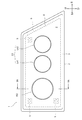
- the scanning mechanism 14 has three blades 14a having the same shape provided around the cylindrical rotating portion 14b, and reflects the light emitted from the light source 12 while rotating.
- a rotary reflector comprising a reflective surface 15 configured to form a desired light distribution pattern.
- the rotation axis r is oblique to the optical axis M of the light source, and is provided on a plane including the optical axis M and the light source 12.
- the shape of the blade 14a is configured so that the secondary light source due to the reflection of the light source 12 is formed near the rear focal point of the projection lens 22. Further, the blade 14a has a twisted shape so that the angle formed by the optical axis Ax and the reflecting surface 15 changes toward the circumferential direction centered on the rotation axis r.
- the scanning mechanism 14 scans the light from the light source 12 in the left-right direction by reflecting the light reflected by the reflecting surface 15 so as to change the direction while rotating around the rotation axis r.
- the projection lens 22 is made of, for example, a translucent resin such as polycarbonate or PMMA, and irradiates the light incident from the blade 14a forward.
- the light from the light source 12 is condensed by the condenser lens 16 and incident on the rotating reflector which is the scanning mechanism 14.
- the light incident on the rotary reflector is scanned left and right by the reflecting surface 15.
- the projection lens 22 receives the light from the rotary reflector and irradiates it forward.
- the high beam unit HU forms a predetermined light distribution pattern by overlapping the light incident at each position of the projection lens 22.
- the low beam unit LU includes a projector-type optical unit Lo1 including a light source which is a light emitting element, a reflector, and a projection lens. Since the optical unit Lo1 has the same configuration as the low beam unit described in, for example, Japanese Patent Application Laid-Open No. 2014-07847, detailed description thereof will be omitted.
- the low beam unit LU includes an optical unit Lo1 and an optical unit Lo2 having the same configuration as the optical unit Lo1, and two optical units Lo1 and Lo2 form a low beam light distribution in front of the vehicle.
- the bracket unit 6 includes a base plate 6a having a shape that follows the front shape of the lamp 1 and three aiming screws E provided at three locations above and below.
- the optical axes of the high beam unit HU and the low beam unit LU are adjusted in the horizontal direction and the vertical direction by rotating each aiming screw E.
- Reference numeral 8 in the light room 4 is an extension, which surrounds the low beam unit LU and the high beam unit HU so as to cover the periphery thereof.
- the condenser lens 16 which is a silicone resin component in the lamp 1 according to the present embodiment will be described.
- the condenser lens 16 is manufactured by injection molding using a highly transparent silicone resin for optical components as a base polymer and a catalyst such as an organic peroxide or a platinum compound as a cross-linking agent.
- the content of the small molecule siloxane in the condenser lens 16 is 0 to 300 ppm in the total amount of D3 to D20.
- the total amount of D11 to D20 is preferably 0 to 290 ppm.
- the content of the small molecule siloxane of D3 to D20 is preferably 0 to 20 ppm.
- the content of D11 to D20 is more preferably 0 to 11 ppm.
- the content of the small molecule siloxane can be controlled, for example, as follows. (1) Use a commercially available low siloxane control grade silicone resin in which low molecular weight siloxane in the material components is removed as much as possible. (2) After injection molding, it is removed by heating at a predetermined temperature (for example, 150 ° C. to 200 ° C.) for a predetermined time (for example, 2 to 4 hours) to release a small molecule siloxane. Heating in this way is called secondary vulcanization, and the residual low-molecular-weight siloxane content can be adjusted by adjusting the heating temperature and heating time.
- a predetermined temperature for example, 150 ° C. to 200 ° C.
- a predetermined time for example, 2 to 4 hours
- the low molecular weight siloxane content is obtained by immersing the silicone resin part after injection molding in an organic solvent and leaving it for a predetermined time (for example, 6 hours) to elute the low molecular weight siloxane contained in the silicone resin part.
- a ketone solvent such as acetone
- an olefin solvent such as normal hexane
- an alcohol such as methyl alcohol, or the like
- the residual small molecule siloxane content can be adjusted by adjusting the type of organic solvent, immersion temperature, and immersion time.
- the condensing lens 16 which is a silicone resin component is the same for each of the lamps of Examples 1 and 2 and Comparative Examples 1 and 2 shown in Table 1 by using the silicone elastomer having the material grade shown in Table 1. It was prepared by injection molding using the mold of No. 1 and post-treatment under the conditions shown in Table 1.
- the measurement of the small molecule siloxane content in the prepared silicone resin part was performed as follows. (1) First, each silicone resin part is cut into 1 to 2 mm squares. (2) Measure the mass of the fragment. (3) Extract with a predetermined amount of normal hexane. (4) The entire amount of the extraction solvent was separated by a gas chromatograph device (gas chromatograph system 7980B manufactured by Agilent Technologies, Ltd.) using a capillary column using helium as a carrier gas (mobile phase) under the condition of an injection temperature of 280 ° C., and FID. (Flame Ionization Detector, hydrogen flame ionization detector) was used for detection.
- gas chromatograph device gas chromatograph system 7980B manufactured by Agilent Technologies, Ltd.
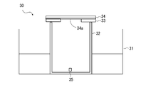
- FIG. 3 is a schematic view showing an outline of the anti-fog performance test facility 30.
- Facility ⁇ Oil bath 31 (capacity 38L, manufactured by Thomas Kagaku Kikai Co., Ltd.) -Glass beaker 32 (volume 1 L, outer diameter ⁇ 95 mm x height 160 mm, glass plate thickness t2.1 mm glass beaker) -Perforated glass plate 33 (a hole with a diameter of 40 mm is opened in the center of a square glass plate of 100 mm x 100 mm x plate thickness t1.9 mm) -PC plate 34 with anti-fog coating 34a (100 mm x 100 mm x t3 mm square PC plate coated with acrylic anti-fog paint P containing an anionic surfactant)
- Method (1) The silicone resin part is cut into 1 to 2 mm squares to obtain a test piece 35.
- Rank 2 Cloudy occurs, but it becomes a water film.
- Rank 3 The whole becomes cloudy for a moment, but soon becomes a water film.
- Rank 4 Partially cloudy, but soon becomes a water film.
- Rank 5 No cloudiness.
- the failure in the anti-fog performance test is due to the low molecular weight siloxane emitted from the condenser lens 16 which is a silicone resin component.
- the low molecule siloxane content of D3 to D20 of the silicone resin component is 300 ppm or less (small molecule of D11 to D20) as in Examples 1 and 2.
- the siloxane concentration is preferably 290 ppm or less).
- the low molecule siloxane content of D3 to D20 is 20 ppm or less (the low molecule siloxane concentration of D11 to D20 is 11 ppm or less) as in Example 2.
- the reason why it is preferable to manage the silicone resin parts by paying attention to the low molecular weight siloxane content of D3 to D20, particularly D11 to D20, is considered as follows.
- the distribution of small molecule siloxanes released from silicone resin products varies with heating temperature. At a heating temperature of 50 ° C., a large amount of D3 to D10 is released centering on D5, but as the heating temperature increases, the amount of low molecular weight siloxane released increases, and at 300 ° C., D14 to D20 predominate.
- the inside of the lighting chamber 4 of the vehicle lighting tool 1 has a relatively high temperature, and in particular, the temperature may reach 100 to 150 ° C.
- the amount of D11 to D20 emitted is large. Therefore, by controlling the content of low molecular weight siloxanes of D3 to D20 contained in the silicone resin component by paying attention to the content of siloxanes of D11 to D20 released, the total amount of low molecular weight siloxanes released is controlled. Can be managed indirectly.
- the content of low molecular weight siloxane contained in the silicone resin component is controlled to prevent deterioration of anti-fog performance. It is the concentration of small molecule siloxane in the air in the lamp room that is directly involved in the deterioration of the anti-fog performance of the anti-fog film, but it is difficult to control this.
- the content of the small molecule siloxane by controlling the content of the small molecule siloxane, the total amount of the small molecule siloxane released into the lamp chamber can be indirectly controlled. Therefore, even if the number and size of the silicone resin parts or the capacity of the lighting room change, it is possible to accurately design the configuration of the silicone resin parts that do not interfere with the anti-fog performance.
- a surfactant is particularly used as the anti-fog paint.
- a containing anti-fog paint it is possible to suppress a decrease in anti-fog performance.
- the condenser lens 16 has been described as an example of the silicone resin component, but the silicone resin component in the present disclosure is not limited to this, and includes various silicone resin components used in vehicle lamps. Needless to say.
Landscapes
- Engineering & Computer Science (AREA)
- General Engineering & Computer Science (AREA)
- Physics & Mathematics (AREA)
- Mechanical Engineering (AREA)
- Chemical & Material Sciences (AREA)
- Chemical Kinetics & Catalysis (AREA)
- General Physics & Mathematics (AREA)
- Optics & Photonics (AREA)
- Non-Portable Lighting Devices Or Systems Thereof (AREA)
- Injection Moulding Of Plastics Or The Like (AREA)
Abstract
Description
(灯具の全体構成)
図1は、本開示の実施の形態に係る灯具1の概略構造を模式的に示す正面図である。図2Aは、灯具1の図1のIIA-IIA線に沿う断面図である。灯具1は、車両前方の左右に配置される一対の前照灯ユニットを有する車両用前照灯装置の、左右いずれか一方の前照灯ユニットである。一対の前照灯ユニットは、実質的に同一の構成を有する。
ここで、本実施の形態にかかる灯具1におけるシリコーン樹脂部品である集光レンズ16について説明する。集光レンズ16は、光学部品用の高透明シリコーン樹脂をベースポリマーとし、例えば、有機過酸化物または白金化合物等の触媒を架橋剤として、射出成形により製造される。集光レンズ16における、低分子シロキサンの含有率は、D3~D20の総量が、0~300ppmである。また、D11~D20の総量は、0~290ppmであると好ましい。D3~D20の低分子シロキサンの含有率は、0~20ppmであると好ましい。D11~D20の含有率は、0~11ppmであるとより好ましい。
(1)材料成分中の低分子シロキサンを極力除去した、市販されている低シロキサン管理グレードのシリコーン樹脂を使用する。
(2)射出成形後、所定の温度(例えば150℃~200℃)で所定時間(例えば、2~4時間)加熱して、低分子シロキサンを放出させることにより除去する。このように加熱することを二次加硫といい、加熱温度および加熱時間を調整することにより、残留する低分子シロキサン含有率を調整することができる。
(3)射出成形後のシリコーン樹脂部品を、有機溶媒に浸漬させて、所定時間(例えば6時間)放置し、シリコーン樹脂部品中に含まれる低分子シロキサンを溶出させることにより、低分子シロキサン含有率を低減する。有機溶媒としては、アセトン等のケトン系溶媒、ノルマルヘキサン等のオレフィン系溶剤、メチルアルコール等のアルコール等を用いることができる。残留する低分子シロキサン含有率は、有機溶媒の種類、浸漬温度、および浸漬時間を調整することにより調整することができる。
以下、本実施の形態にかかる灯具1についての防曇性能を評価するために、それぞれ、低分子シロキサン含有率の異なる集光レンズ16を作成した。そして、作成した集光レンズ16中の低分子シロキサン濃度を測定し、オイルバスを用いた防曇性能試験を行った。オイルバスを用いた防曇性能試験は、シリコーン樹脂部品の試験片を、防曇塗装を施したプレートで覆った、ガラスビーカー内に密閉して、灯具の点灯状態に相当する温度に加熱することで、車両用灯具点灯時に相当する状態を観察することができる試験である。
シリコーン樹脂部品である集光レンズ16は、表1に記載した実施例1,2、および比較例1,2のそれぞれの灯具について、表1に記載した材料グレードを有するシリコーンエラストマーを用いて、同一の金型を用いて射出成形し、表1に示す条件で後処理をおこなって作成した。
作成したシリコーン樹脂部品における低分子シロキサン含有率の測定は、以下のようにして行った。
(1)まず、各シリコーン樹脂部品を1~2mm角に裁断する。
(2)断片の質量を測定する。
(3)所定量のノルマルヘキサンで抽出する。
(4)抽出溶媒全量を、注入温度280℃の条件で、ヘリウムをキャリアガス(移動相)として、キャピラリーカラムを用いたガスクロマトグラフ装置(アジレント・テクノロジー株式会社製のガスクロシステム7980B)で分離し、FID(Flame Ionization Detector, 水素炎イオン化型検出器)を用いて検出した。
(5)結果から、D3~D10およびD11~D20のそれぞれの低分子シロキサンを定量し、それぞれの総量を算出して、(2)で求めた質量から低分子シロキサン含有率(ppm)を算出した。
防曇性能試験は、以下の設備を用い以下の方法の通り行った。図3は、防曇性能試験設備30の概要を示す模式図である。
設備:
・オイルバス31(容量38L,トーマス科学器械株式会社製)
・ガラスビーカー32(容積1L,外径φ95mm×高さ160mm,ガラス板厚t2.1mmのガラスビーカー)
・穴あきガラス板33(100mm×100mm×板厚t1.9mmの正方形ガラス板の中央部に、直径40mmの穴を開口したもの)
・防曇塗装34a付きPCプレート34(100mm×100mm×t3mmの正方形PCプレートにアニオン系の界面活性剤を含むアクリル系防曇塗料Pを塗布したもの)
方法:
(1)シリコーン樹脂部品を1~2mm角に裁断して試験片35とする。
(2)ガラスビーカー32に、試験片35を0.8g秤量して投入する。
(3)ガラスビーカー32に防曇塗装付きPCプレート34を取りつけた穴あきガラス板をセットする。
(4)ガラスビーカー32の底面から64mmの深さのオイルバス31につけて130℃で20時間加熱する。
(5)加熱後、防曇塗装付きPCプレート34を取り外し、約40℃のスチームを20秒間吹き付けて、防曇膜の状態を目視により観察する。
(6)防曇膜の状態を、以下の5つのランクに分類して評価した。また、ランク4以上を合格とした。
ランク1:曇りが発生し、晴れない。
ランク2:曇りが発生するが、水膜になる。
ランク3:全体が一瞬曇るが、すぐに水膜になる。
ランク4:一部曇りが発生するがすぐに水膜になる。
ランク5:曇りなし。

Claims (6)
- 照射方向が開口したランプボディと、
前記開口を覆って灯室を画成し、内表面に合成樹脂を主成分とする防曇膜を備える前面カバーと、
前記灯室内に配置される光源と、
前記灯室内に配置されるシリコーン樹脂部品とを備え、
前記シリコーン樹脂部品におけるD3~D20の環状低分子シロキサン含有率が質量換算で0~300ppmである、車両用灯具。 - 前記灯室内に配置されるレンズを備え、
前記シリコーン樹脂部品の少なくとも1つは、前記レンズである、請求項1に記載の車両用灯具。 - 前記シリコーン樹脂部品におけるD11~D20の環状低分子シロキサン含有率が質量換算で0~290ppmである、請求項1または2に記載の車両用灯具。
- 前記D3~D20の環状低分子シロキサン含有率が、質量換算で0~20ppmである、請求項1~3の何れか一項に記載の車両用灯具。
- D11~D20の環状低分子シロキサン含有率が、質量換算で0~11ppmである、請求項1~4の何れか一項に記載の車両用灯具。
- 前記防曇膜は、アニオン系、カチオン系およびノニオン系の何れか界面活性剤を含む防曇塗料を含んでなる、請求項1~5の何れか一項に記載の車両用灯具。
Priority Applications (3)
| Application Number | Priority Date | Filing Date | Title |
|---|---|---|---|
| US17/922,716 US11746985B2 (en) | 2020-05-01 | 2021-04-16 | Vehicle lamp having a silicone resin part comprising low molecular weight siloxanes |
| CN202180030879.2A CN115485500B (zh) | 2020-05-01 | 2021-04-16 | 车辆用灯具 |
| EP21797631.5A EP4144500B1 (en) | 2020-05-01 | 2021-04-16 | Vehicle lamp |
Applications Claiming Priority (2)
| Application Number | Priority Date | Filing Date | Title |
|---|---|---|---|
| JP2020-081466 | 2020-05-01 | ||
| JP2020081466A JP7337025B2 (ja) | 2020-05-01 | 2020-05-01 | 車両用灯具 |
Publications (1)
| Publication Number | Publication Date |
|---|---|
| WO2021220848A1 true WO2021220848A1 (ja) | 2021-11-04 |
Family
ID=78300480
Family Applications (1)
| Application Number | Title | Priority Date | Filing Date |
|---|---|---|---|
| PCT/JP2021/015739 Ceased WO2021220848A1 (ja) | 2020-05-01 | 2021-04-16 | 車両用灯具 |
Country Status (5)
| Country | Link |
|---|---|
| US (1) | US11746985B2 (ja) |
| EP (1) | EP4144500B1 (ja) |
| JP (1) | JP7337025B2 (ja) |
| CN (1) | CN115485500B (ja) |
| WO (1) | WO2021220848A1 (ja) |
Cited By (1)
| Publication number | Priority date | Publication date | Assignee | Title |
|---|---|---|---|---|
| JP2024025438A (ja) * | 2022-08-12 | 2024-02-26 | トヨタ自動車株式会社 | 車両用ランプ |
Citations (6)
| Publication number | Priority date | Publication date | Assignee | Title |
|---|---|---|---|---|
| JP2005146227A (ja) | 2003-11-20 | 2005-06-09 | Hitachi Chem Co Ltd | 防曇塗料、防曇性成形品及び防曇塗料の製造方法 |
| JP2011119094A (ja) * | 2009-12-02 | 2011-06-16 | Koito Mfg Co Ltd | 車両用灯具 |
| JP2014078476A (ja) | 2012-10-12 | 2014-05-01 | Koito Mfg Co Ltd | 車両用前照灯装置 |
| JP2019093564A (ja) | 2017-11-17 | 2019-06-20 | 株式会社小糸製作所 | 2色成形レンズ |
| JP2019102389A (ja) | 2017-12-07 | 2019-06-24 | 株式会社小糸製作所 | 光源ユニットと光源ユニットのレンズ固定方法 |
| JP2020081466A (ja) | 2018-11-27 | 2020-06-04 | 株式会社大一商会 | 遊技機 |
Family Cites Families (9)
| Publication number | Priority date | Publication date | Assignee | Title |
|---|---|---|---|---|
| US6520650B2 (en) * | 1999-02-08 | 2003-02-18 | Valeo Sylvania L.C.C. | Lamp reflector with a barrier coating of a plasma polymer |
| US7790292B2 (en) * | 1999-05-18 | 2010-09-07 | Sabic Innovative Plastics Ip B.V. | Polysiloxane copolymers, thermoplastic composition, and articles formed therefrom |
| CN101186756A (zh) * | 2006-05-02 | 2008-05-28 | 信越化学工业株式会社 | 降低了低分子硅氧烷挥发量的难燃树脂组合物 |
| JP4497329B2 (ja) * | 2007-09-03 | 2010-07-07 | 信越化学工業株式会社 | マイクロコンタクトプリント用版材及びその製造方法 |
| WO2011107592A1 (en) * | 2010-03-05 | 2011-09-09 | Momentive Performance Materials Gmbh | Curable polyorganosiloxane composition for use as an encapsulant for a solar cell module |
| WO2011118109A1 (ja) * | 2010-03-23 | 2011-09-29 | 株式会社朝日ラバー | 可撓性反射基材、その製造方法及びその反射基材に用いる原材料組成物 |
| JP2012074644A (ja) * | 2010-09-30 | 2012-04-12 | Shin Etsu Chem Co Ltd | マイクロコンタクトプリント用版材及びその製造方法 |
| WO2019064973A1 (ja) * | 2017-09-29 | 2019-04-04 | 富士フイルム株式会社 | 防曇層積層体 |
| CN108194894A (zh) * | 2018-01-16 | 2018-06-22 | 上海小糸车灯有限公司 | 一种车灯配光镜 |
-
2020
- 2020-05-01 JP JP2020081466A patent/JP7337025B2/ja active Active
-
2021
- 2021-04-16 CN CN202180030879.2A patent/CN115485500B/zh active Active
- 2021-04-16 US US17/922,716 patent/US11746985B2/en active Active
- 2021-04-16 EP EP21797631.5A patent/EP4144500B1/en active Active
- 2021-04-16 WO PCT/JP2021/015739 patent/WO2021220848A1/ja not_active Ceased
Patent Citations (6)
| Publication number | Priority date | Publication date | Assignee | Title |
|---|---|---|---|---|
| JP2005146227A (ja) | 2003-11-20 | 2005-06-09 | Hitachi Chem Co Ltd | 防曇塗料、防曇性成形品及び防曇塗料の製造方法 |
| JP2011119094A (ja) * | 2009-12-02 | 2011-06-16 | Koito Mfg Co Ltd | 車両用灯具 |
| JP2014078476A (ja) | 2012-10-12 | 2014-05-01 | Koito Mfg Co Ltd | 車両用前照灯装置 |
| JP2019093564A (ja) | 2017-11-17 | 2019-06-20 | 株式会社小糸製作所 | 2色成形レンズ |
| JP2019102389A (ja) | 2017-12-07 | 2019-06-24 | 株式会社小糸製作所 | 光源ユニットと光源ユニットのレンズ固定方法 |
| JP2020081466A (ja) | 2018-11-27 | 2020-06-04 | 株式会社大一商会 | 遊技機 |
Non-Patent Citations (1)
| Title |
|---|
| See also references of EP4144500A4 |
Cited By (2)
| Publication number | Priority date | Publication date | Assignee | Title |
|---|---|---|---|---|
| JP2024025438A (ja) * | 2022-08-12 | 2024-02-26 | トヨタ自動車株式会社 | 車両用ランプ |
| JP7704101B2 (ja) | 2022-08-12 | 2025-07-08 | トヨタ自動車株式会社 | 車両用ランプ |
Also Published As
| Publication number | Publication date |
|---|---|
| EP4144500A4 (en) | 2023-10-11 |
| CN115485500B (zh) | 2025-06-06 |
| EP4144500B1 (en) | 2025-07-09 |
| JP7337025B2 (ja) | 2023-09-01 |
| US11746985B2 (en) | 2023-09-05 |
| JP2021176135A (ja) | 2021-11-04 |
| CN115485500A (zh) | 2022-12-16 |
| EP4144500A1 (en) | 2023-03-08 |
| US20230167963A1 (en) | 2023-06-01 |
Similar Documents
| Publication | Publication Date | Title |
|---|---|---|
| US9033560B2 (en) | Opaque and movable element preventing solar rays from focusing in a headlamp | |
| US10228118B2 (en) | Vehicular lamp | |
| US9039261B2 (en) | Vehicular lamp | |
| KR102121631B1 (ko) | 광 빔 방사 장치, 및 상기 장치를 포함하는 특히 자동차용 헤드라이트 | |
| CN102756682B (zh) | 汽车头灯的光模块 | |
| US20100027284A1 (en) | Light Module for an Illumination Device for a Motor Vehicle | |
| JP2005150041A (ja) | 灯具 | |
| JP2010262767A (ja) | 車輌用灯具 | |
| WO2021220848A1 (ja) | 車両用灯具 | |
| CN110094690B (zh) | 车辆用灯具 | |
| JP7134744B2 (ja) | フィールド補正光学素子を含んだ発光モジュール | |
| TW200950996A (en) | Vehicle headlight capable of compensating for light intensity of ark region | |
| US6210028B1 (en) | Vehicular headlamp having synthetic resin lens with reduced discoloration and cracking from ultraviolet radiation | |
| JP2017228417A (ja) | 車両用ヘッドランプの防曇構造 | |
| JP6932933B2 (ja) | 車両用前照灯 | |
| JP5780840B2 (ja) | 車両用灯具 | |
| CN103196087B (zh) | 车辆用前照灯 | |
| JP2010262765A (ja) | 車輌用灯具 | |
| JP2016162637A (ja) | 車両用灯具 | |
| JP6904203B2 (ja) | 車両用前照灯 | |
| JP2010262768A (ja) | 車輌用灯具 | |
| JP2010282794A (ja) | 車輌用灯具 | |
| JP2010282938A (ja) | 車輌用前照灯 | |
| JP2019133890A (ja) | 車両用灯具 | |
| JP2025090381A (ja) | 車両用灯具 |
Legal Events
| Date | Code | Title | Description |
|---|---|---|---|
| 121 | Ep: the epo has been informed by wipo that ep was designated in this application |
Ref document number: 21797631 Country of ref document: EP Kind code of ref document: A1 |
|
| ENP | Entry into the national phase |
Ref document number: 2021797631 Country of ref document: EP Effective date: 20221201 |
|
| NENP | Non-entry into the national phase |
Ref country code: DE |
|
| WWG | Wipo information: grant in national office |
Ref document number: 202180030879.2 Country of ref document: CN |
|
| WWG | Wipo information: grant in national office |
Ref document number: 2021797631 Country of ref document: EP |