WO2021221018A1 - 二次電池 - Google Patents
二次電池 Download PDFInfo
- Publication number
- WO2021221018A1 WO2021221018A1 PCT/JP2021/016661 JP2021016661W WO2021221018A1 WO 2021221018 A1 WO2021221018 A1 WO 2021221018A1 JP 2021016661 W JP2021016661 W JP 2021016661W WO 2021221018 A1 WO2021221018 A1 WO 2021221018A1
- Authority
- WO
- WIPO (PCT)
- Prior art keywords
- secondary battery
- exterior body
- metal plate
- electrode
- insulating material
- Prior art date
- Legal status (The legal status is an assumption and is not a legal conclusion. Google has not performed a legal analysis and makes no representation as to the accuracy of the status listed.)
- Ceased
Links
Images




Classifications
-
- H—ELECTRICITY
- H01—ELECTRIC ELEMENTS
- H01M—PROCESSES OR MEANS, e.g. BATTERIES, FOR THE DIRECT CONVERSION OF CHEMICAL ENERGY INTO ELECTRICAL ENERGY
- H01M50/00—Constructional details or processes of manufacture of the non-active parts of electrochemical cells other than fuel cells, e.g. hybrid cells
- H01M50/50—Current conducting connections for cells or batteries
- H01M50/543—Terminals
- H01M50/552—Terminals characterised by their shape
- H01M50/559—Terminals adapted for cells having curved cross-section, e.g. round, elliptic or button cells
-
- H—ELECTRICITY
- H01—ELECTRIC ELEMENTS
- H01M—PROCESSES OR MEANS, e.g. BATTERIES, FOR THE DIRECT CONVERSION OF CHEMICAL ENERGY INTO ELECTRICAL ENERGY
- H01M10/00—Secondary cells; Manufacture thereof
- H01M10/05—Accumulators with non-aqueous electrolyte
- H01M10/052—Li-accumulators
- H01M10/0525—Rocking-chair batteries, i.e. batteries with lithium insertion or intercalation in both electrodes; Lithium-ion batteries
-
- H—ELECTRICITY
- H01—ELECTRIC ELEMENTS
- H01M—PROCESSES OR MEANS, e.g. BATTERIES, FOR THE DIRECT CONVERSION OF CHEMICAL ENERGY INTO ELECTRICAL ENERGY
- H01M50/00—Constructional details or processes of manufacture of the non-active parts of electrochemical cells other than fuel cells, e.g. hybrid cells
- H01M50/10—Primary casings; Jackets or wrappings
- H01M50/102—Primary casings; Jackets or wrappings characterised by their shape or physical structure
- H01M50/109—Primary casings; Jackets or wrappings characterised by their shape or physical structure of button or coin shape
-
- H—ELECTRICITY
- H01—ELECTRIC ELEMENTS
- H01M—PROCESSES OR MEANS, e.g. BATTERIES, FOR THE DIRECT CONVERSION OF CHEMICAL ENERGY INTO ELECTRICAL ENERGY
- H01M50/00—Constructional details or processes of manufacture of the non-active parts of electrochemical cells other than fuel cells, e.g. hybrid cells
- H01M50/10—Primary casings; Jackets or wrappings
- H01M50/147—Lids or covers
- H01M50/148—Lids or covers characterised by their shape
- H01M50/153—Lids or covers characterised by their shape for button or coin cells
-
- H—ELECTRICITY
- H01—ELECTRIC ELEMENTS
- H01M—PROCESSES OR MEANS, e.g. BATTERIES, FOR THE DIRECT CONVERSION OF CHEMICAL ENERGY INTO ELECTRICAL ENERGY
- H01M50/00—Constructional details or processes of manufacture of the non-active parts of electrochemical cells other than fuel cells, e.g. hybrid cells
- H01M50/10—Primary casings; Jackets or wrappings
- H01M50/172—Arrangements of electric connectors penetrating the casing
- H01M50/174—Arrangements of electric connectors penetrating the casing adapted for the shape of the cells
- H01M50/181—Arrangements of electric connectors penetrating the casing adapted for the shape of the cells for button or coin cells
-
- H—ELECTRICITY
- H01—ELECTRIC ELEMENTS
- H01M—PROCESSES OR MEANS, e.g. BATTERIES, FOR THE DIRECT CONVERSION OF CHEMICAL ENERGY INTO ELECTRICAL ENERGY
- H01M50/00—Constructional details or processes of manufacture of the non-active parts of electrochemical cells other than fuel cells, e.g. hybrid cells
- H01M50/10—Primary casings; Jackets or wrappings
- H01M50/183—Sealing members
- H01M50/186—Sealing members characterised by the disposition of the sealing members
- H01M50/188—Sealing members characterised by the disposition of the sealing members the sealing members being arranged between the lid and terminal
-
- Y—GENERAL TAGGING OF NEW TECHNOLOGICAL DEVELOPMENTS; GENERAL TAGGING OF CROSS-SECTIONAL TECHNOLOGIES SPANNING OVER SEVERAL SECTIONS OF THE IPC; TECHNICAL SUBJECTS COVERED BY FORMER USPC CROSS-REFERENCE ART COLLECTIONS [XRACs] AND DIGESTS
- Y02—TECHNOLOGIES OR APPLICATIONS FOR MITIGATION OR ADAPTATION AGAINST CLIMATE CHANGE
- Y02E—REDUCTION OF GREENHOUSE GAS [GHG] EMISSIONS, RELATED TO ENERGY GENERATION, TRANSMISSION OR DISTRIBUTION
- Y02E60/00—Enabling technologies; Technologies with a potential or indirect contribution to GHG emissions mitigation
- Y02E60/10—Energy storage using batteries
-
- Y—GENERAL TAGGING OF NEW TECHNOLOGICAL DEVELOPMENTS; GENERAL TAGGING OF CROSS-SECTIONAL TECHNOLOGIES SPANNING OVER SEVERAL SECTIONS OF THE IPC; TECHNICAL SUBJECTS COVERED BY FORMER USPC CROSS-REFERENCE ART COLLECTIONS [XRACs] AND DIGESTS
- Y02—TECHNOLOGIES OR APPLICATIONS FOR MITIGATION OR ADAPTATION AGAINST CLIMATE CHANGE
- Y02P—CLIMATE CHANGE MITIGATION TECHNOLOGIES IN THE PRODUCTION OR PROCESSING OF GOODS
- Y02P70/00—Climate change mitigation technologies in the production process for final industrial or consumer products
- Y02P70/50—Manufacturing or production processes characterised by the final manufactured product
Definitions
- the present invention relates to a secondary battery.
- the present invention relates to a secondary battery comprising an electrode assembly comprising an electrode constituent layer including a positive electrode, a negative electrode and a separator.
- the secondary battery is a so-called storage battery, it can be repeatedly charged and discharged, and is used for various purposes.
- secondary batteries are used in mobile devices such as mobile phones, smartphones and notebook computers.
- the inventors of the present application realized that the conventional secondary battery had a problem to be overcome, and found that it was necessary to take measures for that purpose. Specifically, the inventors of the present application have found that there are the following problems.
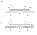
- a flat metal plate 120 is an electrode on a metal exterior body or an exterior case 130 via an insulating material or a sealing member 140. It is adhered as a terminal 101 (for example, Patent Document 1).
- an electrode assembly 110 including, for example, an electrode constituent layer including a positive electrode, a negative electrode, and a separator is arranged inside the exterior body 130 of the secondary battery 100.
- a tab 160 extending from one of the positive electrode and the negative electrode of the electrode assembly 110 is electrically connected to the metal plate 120.
- a tab 170 extending from the other of the positive electrode and the negative electrode is electrically connected to the exterior body 130. Therefore, the metal plate 120 and the exterior body 130 can each function as electrode terminals (positive electrode terminals or negative electrode terminals).
- the exterior body 230 having an opening also has an opening on the upper side.
- the insulating materials 240 concentrically and arranging them and further arranging the flat metal plate 220 concentrically on the upper side thereof and pressing in the direction of the arrow while heating, for example, from a thermoplastic resin or the like.
- the electrode terminal 201 as shown in FIG. 11B cross-sectional view in the radial direction
- the tab 260 extending from the electrode assembly can be electrically connected to the metal plate 220 through the openings of the exterior body 230 and the insulating material 240. Further, such an insulating material 240 can prevent an electrical short circuit between the metal plate 220 and the exterior body 230.
- the metal plate 220 may be peeled off from the insulating material 240 due to an increase in pressure inside the battery, for example, according to the present invention. It was found by their research. Further, it has been found from the research by the inventors of the present application that the insulating material 240 may also be peeled off from the exterior body 230 in the same manner. From these facts, it was found that the insulating property between the metal plate and the exterior body is lowered, and the safety of the battery itself is lowered.
- a main object of the present invention is to provide a secondary battery in which the insulating property and the sealing property between the metal plate provided as the electrode terminal and the exterior body are further improved.
- the secondary battery according to the present invention is A secondary battery including an electrode assembly and an exterior body for accommodating the electrode assembly.
- the exterior body is provided with a metal plate joined via an insulating material.
- the exterior body has an opening, and one of the peripheral edge of the opening and the outer edge of the metal plate is bent so as to be separated from the insulating material.
- the above-mentioned secondary battery may be referred to as "the secondary battery of the present disclosure”.
- FIG. 1 is a cross-sectional view schematically showing the configuration of the electrode assembly (FIG. 1 (A): electrode assembly having a non-winding plane laminated structure, FIG. 1 (B): electrodes having a wound structure. Assembly).
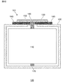
- FIG. 2 is a schematic cross-sectional view schematically showing a secondary battery according to an embodiment of the present invention.
- FIG. 3 is a schematic cross-sectional view schematically showing a secondary battery according to another embodiment of the present invention.
- FIG. 4 is a schematic cross-sectional view schematically showing a configuration around an electrode terminal of a secondary battery according to an embodiment of the present invention.
- FIG. 5 is a schematic cross-sectional view schematically showing a change or increase in thickness of the insulating material of the secondary battery.
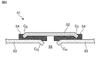
- FIG. 6 is a schematic cross-sectional view schematically showing a configuration around an electrode terminal of a secondary battery according to another embodiment of the present invention.
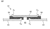
- FIG. 7 is a schematic cross-sectional view schematically showing a configuration around an electrode terminal of a secondary battery according to another embodiment of the present invention.
- FIG. 8 is a schematic cross-sectional view schematically showing a secondary battery according to a preferred embodiment of the present invention.
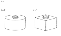
- FIG. 9 is a schematic perspective view for illustrating (a) a button-shaped or coin-shaped and (b) square-shaped secondary battery.
- FIG. 10 is a schematic cross-sectional view schematically showing a conventional secondary battery.
- FIG. 11 is a schematic view schematically showing the configuration around the electrode terminals of the conventional secondary battery.
- the "cross-sectional view” described directly or indirectly herein basically refers to a secondary battery along the stacking direction or stacking direction of the electrode assembly or electrode constituent layers that make up the secondary battery. It is based on a cut-out virtual cross section (see Figure 1).
- the direction of "thickness”, which is directly or indirectly described herein is basically based on the stacking direction of the electrode materials that make up the secondary battery.
- the direction of "thickness” corresponds to the plate thickness direction of such a secondary battery.
- the "plan view” or “plan view shape” used in the present specification is based on a sketch of an object viewed from above or below along the direction of such thickness (that is, the above-mentioned stacking direction).
- the "vertical direction” and the “horizontal direction” used directly or indirectly in the present specification correspond to the vertical direction and the horizontal direction in the figure, respectively. Unless otherwise specified, the same code or symbol shall indicate the same member or part or the same meaning.
- the vertical downward direction ie, the direction in which gravity acts
- the opposite direction corresponds to the "upward direction”. It can be regarded as equivalent.
- Secondary battery refers to a battery that can be repeatedly charged and discharged. Therefore, the secondary battery of the present disclosure is not overly bound by its name, and may include, for example, a power storage device.
- the secondary battery of the present disclosure comprises, for example, an electrode assembly in which electrode constituent layers including a positive electrode, a negative electrode and a separator are laminated.
- FIGS. 1 (A) and 1 (B) schematically illustrate the electrode assembly 10.
- the positive electrode 1 and the negative electrode 2 may be stacked with each other via the separator 3 to form an electrode constituent layer 5.
- At least one or more of such electrode constituent layers 5 may be laminated to form an electrode assembly.
- the electrode constituent layers 5 have a planar laminated structure in which the electrode constituent layers 5 are laminated in a planar manner.
- FIG. 1B the electrode constituent layer 5 has a wound laminated structure in which the electrode constituent layer 5 is wound in a wound shape. That is, FIG.
- the electrode assembly 10 has a wound laminated structure (for example, a jelly roll structure) in which an electrode constituent layer including a positive electrode, a negative electrode, and a separator arranged between the positive electrode and the negative electrode is wound in a roll shape.
- the electrode assembly 10 may have a two-dimensional laminated structure in which the electrode constituent layers 5 are laminated so as to be stacked with each other, for example, as shown in FIG. 1 (A).
- the electrode assembly 10 may have a winding structure in which the electrode constituent layer 5 extending in a strip shape for a relatively long time is wound in a roll shape, for example, as shown in FIG. 1 (B). .. Note that FIG.
- FIG. 1B merely illustrates a wound structure of the electrode assembly, and the electrode assembly is placed inside the exterior with the cross section shown in FIG. 1B set to "upward” or “downward". It may be placed in.
- an electrode assembly may be enclosed in an exterior body together with an electrolyte (for example, a non-aqueous electrolyte).
- the structure of the electrode assembly is not necessarily limited to the plane laminated structure (see FIG. 1 (A)) or the wound laminated structure (see FIG. 1 (B)).
- the electrode assembly may have a so-called stack-and-folding structure in which a positive electrode, a separator, and a negative electrode are laminated on a long film and then folded.
- the positive electrode is composed of at least a positive electrode material layer and, if necessary, a positive electrode current collector.
- a positive electrode material layer is provided on at least one surface of the positive electrode current collector.
- the positive electrode material layer contains a positive electrode active material as an electrode active material.
- each of the plurality of positive electrodes in the electrode assembly may have positive electrode material layers provided on both sides of the positive electrode current collector, or positive electrode material layers may be provided on only one side of the positive electrode current collector. It may be the one that exists.
- the positive electrode current collector may have a foil form. That is, the positive electrode current collector may be composed of the metal foil.
- the negative electrode is composed of at least a negative electrode material layer and, if necessary, a negative electrode current collector.
- a negative electrode material layer is provided on at least one surface of the negative electrode current collector.
- the negative electrode material layer contains a negative electrode active material as an electrode active material.
- each of the plurality of negative electrodes in the electrode assembly may have negative electrode material layers provided on both sides of the negative electrode current collector, or negative electrode material layers may be provided on only one side of the negative electrode current collector. It may be the one that exists.
- the negative electrode current collector may have a foil form. That is, the negative electrode current collector may be composed of the metal foil.
- the electrode active material that is, the positive electrode active material and the negative electrode active material, which can be contained in the positive electrode material layer and the negative electrode material layer, are substances that can be directly involved in the transfer of electrons in the secondary battery, respectively, and are charged and discharged, that is, the battery reaction. It is the main material of the positive electrode and the negative electrode.
- ions can be brought to the electrolyte due to the "positive electrode active material that can be contained in the positive electrode material layer" and the "negative electrode active material that can be contained in the negative electrode material layer". Such ions may move between the positive electrode and the negative electrode to transfer electrons and charge / discharge.
- the positive electrode material layer and the negative electrode material layer may be particularly layers capable of occluding and releasing lithium ions. That is, the secondary battery according to the embodiment of the present invention is a non-aqueous electrolyte secondary battery in which lithium ions can move between the positive electrode and the negative electrode via the non-aqueous electrolyte to charge and discharge the battery. You may be.
- the secondary battery according to the embodiment of the present invention can correspond to a so-called "lithium ion battery".
- the lithium ion battery has a layer in which the positive electrode and the negative electrode can occlude and release lithium ions.
- the positive electrode active material of the positive electrode material layer may be composed of, for example, granules, and a binder may be contained in the positive electrode material layer for more sufficient contact between particles and shape retention.
- a conductive auxiliary agent may be contained in the positive electrode material layer in order to facilitate the transfer of electrons that promote the battery reaction.
- the negative electrode active material of the negative electrode material layer may be composed of, for example, granules, and a binder may be contained in the negative electrode material layer for more sufficient contact between particles and shape retention.
- a conductive auxiliary agent may be contained in the negative electrode material layer in order to facilitate the transfer of electrons that promote the battery reaction.
- the positive electrode material layer and the negative electrode material layer can also be referred to as a "positive electrode mixture layer” and a “negative electrode mixture layer”, respectively.
- the positive electrode active material may be, for example, a substance that contributes to the occlusion and release of lithium ions. From this point of view, the positive electrode active material may be, for example, a lithium-containing composite oxide. More specifically, the positive electrode active material may be a lithium transition metal composite oxide containing lithium and at least one transition metal selected from the group consisting of cobalt, nickel, manganese and iron.
- such a lithium transition metal composite oxide may be contained as a positive electrode active material in the positive electrode material layer of the secondary battery according to the embodiment of the present invention.
- the positive electrode active material may be lithium cobalt oxide, lithium nickel oxide, lithium manganate, lithium iron phosphate, or a part of the transition metal thereof replaced with another metal.
- Such a positive electrode active material may be contained as a single species, it may be contained in combination of two or more species.
- the binder that can be contained in the positive electrode material layer is not particularly limited, but is limited to polyvinylidene fluoride, vinylidene fluoride-hexafluoropropylene copolymer, vinylidene fluoride-tetrafluoroethylene copolymer, and polytetrafluoroethylene. At least one species selected from the group consisting of the above can be mentioned.
- the conductive auxiliary agent that can be contained in the positive electrode material layer is not particularly limited, but is limited to carbon black such as thermal black, furnace black, channel black, ketjen black and acetylene black, graphite, carbon nanotubes, and vapor phase growth. At least one selected from carbon fibers such as carbon fibers, metal powders such as copper, nickel, aluminum and silver, and polyphenylene derivatives can be mentioned.
- the thickness dimension of the positive electrode material layer is not particularly limited, but may be 1 ⁇ m or more and 300 ⁇ m or less, for example, 5 ⁇ m or more and 200 ⁇ m or less.
- the thickness dimension of the positive electrode material layer is the thickness inside the secondary battery, and the average value of the measured values at any 10 points may be adopted.
- the negative electrode active material may be a substance that contributes to the occlusion and release of lithium ions. From this point of view, the negative electrode active material may be, for example, various carbon materials, oxides, and / or lithium alloys, metallic lithium, and the like.
- Examples of various carbon materials for the negative electrode active material include graphite (specifically, natural graphite and / or artificial graphite, etc.), hard carbon, soft carbon, and / or diamond-like carbon.
- graphite has high electron conductivity and, for example, excellent adhesion to a negative electrode current collector.
- the oxide of the negative electrode active material at least one selected from the group consisting of silicon oxide, tin oxide, indium oxide, zinc oxide, lithium oxide and the like can be mentioned.
- Such an oxide may be amorphous as its structural form. This is because deterioration due to non-uniformity such as grain boundaries or defects is less likely to occur.
- the lithium alloy of the negative electrode active material may be an alloy of a metal that can be alloyed with lithium, for example, Al, Si, Pb, Sn, In, Bi, Ag, Ba, Ca, Hg, Pd, Pt, Te, It may be a binary, ternary or higher alloy of a metal such as Zn or La and lithium.
- Such an alloy may be amorphous as its structural form. This is because deterioration due to non-uniformity such as grain boundaries or defects is less likely to occur.
- the binder that can be contained in the negative electrode material layer is not particularly limited, but is at least one selected from the group consisting of styrene-butadiene rubber, polyacrylic acid, polyvinylidene fluoride, polyimide-based resin, and polyamide-imide-based resin. Can be mentioned.
- the conductive auxiliary agent that can be contained in the negative electrode material layer is not particularly limited, but is limited to carbon black such as thermal black, furnace black, channel black, ketjen black and acetylene black, graphite, carbon nanotubes, and vapor phase growth. At least one selected from carbon fibers such as carbon fibers, metal powders such as copper, nickel, aluminum and silver, and polyphenylene derivatives can be mentioned.
- the thickness dimension of the negative electrode material layer is not particularly limited, but may be 1 ⁇ m or more and 300 ⁇ m or less, for example, 5 ⁇ m or more and 200 ⁇ m or less.
- the thickness dimension of the negative electrode material layer is the thickness inside the secondary battery, and the average value of the measured values at any 10 points may be adopted.
- the positive electrode current collector and the negative electrode current collector that can be used for the positive electrode and the negative electrode are members capable of collecting and supplying electrons generated by the electrode active material due to the battery reaction.
- Such an electrode current collector may be a sheet-shaped metal member. Further, such an electrode current collector may have a perforated or perforated form.
- the current collector may be a plate, a metal foil, a punching metal, a net, an expanded metal, or the like.
- the positive electrode current collector that can be used for the positive electrode may be made of a metal foil containing at least one selected from the group consisting of aluminum, stainless steel (SUS), nickel and the like.
- the positive electrode current collector may be, for example, an aluminum foil.
- the negative electrode current collector that can be used for the negative electrode may be made of a metal foil containing at least one selected from the group consisting of copper, stainless steel (SUS), nickel and the like.
- the negative electrode current collector may be, for example, a copper foil.
- stainless steel refers to, for example, stainless steel defined in “JIS G0203 steel terminology", and is an alloy steel containing chromium or chromium and nickel. It's okay.
- the thickness dimensions of the positive electrode current collector and the negative electrode current collector are not particularly limited, but may be 1 ⁇ m or more and 100 ⁇ m or less, for example, 10 ⁇ m or more and 70 ⁇ m or less.
- Each thickness dimension of the positive electrode current collector and the negative electrode current collector is the thickness inside the secondary battery, and the average value of the measured values at any 10 points may be adopted.
- the separator that can be used for the positive electrode and the negative electrode is a member that can be provided from the viewpoint of preventing a short circuit due to contact between the positive electrode and the negative electrode and retaining the electrolyte.
- the separator is a member capable of passing ions while preventing electronic contact between the positive electrode and the negative electrode.
- the separator is a porous or microporous insulating member, and may have a film morphology due to its small thickness.
- a microporous polyolefin membrane may be used as the separator.
- the microporous membrane that can be used as a separator may contain, for example, only polyethylene (PE) or polypropylene (PP) as the polyolefin.
- the separator may be a laminate that can be composed of a "microporous membrane made of PE” and a "microporous membrane made of PP".
- the surface of the separator may be covered with an inorganic particle coat layer and / or an adhesive layer or the like.
- the surface of the separator may have adhesiveness.
- the thickness dimension of the separator is not particularly limited, but may be 1 ⁇ m or more and 100 ⁇ m or less, for example, 2 ⁇ m or more and 20 ⁇ m or less.
- the thickness dimension of the separator is the thickness inside the secondary battery (particularly the thickness between the positive electrode and the negative electrode), and the average value of the measured values at any 10 points may be adopted.
- the separator should not be particularly bound by its name, and may be a solid electrolyte, a gel-like electrolyte, and / or insulating inorganic particles having the same function.
- an electrode assembly including an electrode constituent layer including a positive electrode, a negative electrode and a separator may be enclosed in an exterior body together with an electrolyte.
- the electrolyte can assist in the movement of metal ions released from the electrodes (positive electrode and / or negative electrode).
- the electrolyte may be an organic electrolyte and / or a "non-aqueous" electrolyte comprising organic solvents and the like, or it may be a "water-based" electrolyte containing water.
- the electrolyte is a "non-aqueous" electrolyte (hereinafter, “non-aqueous electrolyte”) containing a lithium ion-containing electrolyte or an organic electrolyte and / or an organic solvent. ”) Is preferable. That is, it is preferable that the electrolyte is a non-aqueous electrolyte. In the electrolyte, there will be metal ions released from the electrodes (positive electrode and / or negative electrode), and therefore the electrolyte can assist in the movement of the metal ions in the battery reaction.
- the secondary battery according to the embodiment of the present invention is preferably a non-aqueous electrolyte secondary battery in which a "non-aqueous" electrolyte containing a "non-aqueous” solvent and a solute is used as the electrolyte.
- the electrolyte may have a form such as liquid or gel (note that the “liquid” non-aqueous electrolyte is also referred to as “non-aqueous electrolyte solution” in the present specification).
- the non-aqueous electrolyte is preferably an electrolyte containing a non-aqueous solvent and a solute.
- the specific solvent for the non-aqueous electrolyte may contain at least carbonate. Such carbonates may be cyclic carbonates and / or chain carbonates.
- the cyclic carbonates include at least one selected from the group consisting of propylene carbonate (PC), ethylene carbonate (EC), butylene carbonate (BC) and vinylene carbonate (VC). be able to.
- PC propylene carbonate
- EC ethylene carbonate
- BC butylene carbonate
- VC vinylene carbonate
- chain carbonates include at least one selected from the group consisting of dimethyl carbonate (DMC), diethyl carbonate (DEC), ethyl methyl carbonate (EMC) and dipropyl carbonate (DPC).
- DMC dimethyl carbonate
- DEC diethyl carbonate
- EMC ethyl methyl carbonate
- DPC dipropyl carbonate
- a combination of cyclic carbonates and chain carbonates may be used as the non-aqueous electrolyte, for example ethylene carbonate (EC) and diethyl carbonate ( A mixture with DEC), a mixture of ethylene carbonate (EC) and ethyl methyl carbonate (EMC), and the like may be used.
- a specific non-aqueous electrolyte solute for example, a Li salt such as LiPF 6 and / or LiBF 4 may be used.
- the "exterior body" of a secondary battery generally means a member capable of accommodating or wrapping an electrode assembly in which electrode constituent layers including a positive electrode, a negative electrode and a separator are laminated.
- the exterior body may be an electrically conductive or conductive exterior body, and may be a metal exterior body. Further, such a metal exterior body may have a two-part configuration that can be composed of a cup-shaped member and a lid-shaped member.
- the "cup-shaped member” has a side surface portion corresponding to a body portion and a main surface portion (in a typical embodiment, for example, a lower surface) continuous with the side surface portion, and a hollow portion is formed inside. It means a member.
- the "lid-shaped member” means a member provided so as to cover such a cup-shaped member.
- the lid-shaped member may be, for example, a single member (typically a flat plate-shaped member) extending in the same plane.
- the lid-shaped member and the cup-shaped member may be arbitrarily combined so that the lid-shaped member and the upper end portion of the cup-shaped member engage, connect, or fit with each other.
- the "cup-shaped member” and the “lid-shaped member” may be joined by a welding process, which may enable relatively simple encapsulation of the electrode assembly.
- the secondary battery of the present invention is characterized with respect to an exterior body and peripheral parts thereof capable of wrapping or accommodating the electrode assembly.
- it is characterized in terms of elements related to the exterior of the secondary battery and the electrode terminals (positive electrode terminal and / or negative electrode terminal) that can be attached to the exterior body of the secondary battery.
- the bonding region between the exterior body and the electrode terminal is a region that cannot be seen before.
- the electrode terminals of the secondary battery can be made of, for example, a metal plate, provided on the exterior via an insulating material, and electrically connected to a tab (or lead) that can extend from the electrode assembly. It is structured so that it can be done.
- the exterior body is provided with an opening through which a tab or the like passes, and an electrode terminal such as a metal plate is joined to the surface around the opening via an insulating material.
- the exterior body is provided with a metal plate bonded (or bonded or bonded or bonded) via an insulating material. That is, in the joint region, the insulating material has a form that can be sandwiched between the metal plate and the exterior body.
- the main feature of the secondary battery of the present invention is that one of the "peripheral edge of the opening of the exterior body" and the “outer edge edge of the metal plate” is “bent away from the insulating material" (FIGS. 1 to 1 to 1). 8).
- the secondary battery of the present invention will be described in more detail with reference to some embodiments.
- the secondary battery 20 has an electrode assembly 10 (see FIG. 1) and an exterior body (23) capable of accommodating the electrode assembly 10. Consists of having.
- the exterior body is preferably a metal exterior body, and may be composed of, for example, a lid-shaped member 23a and a cup-shaped member 23b as shown in FIG. Sometimes called "body 23").
- the exterior body 23 (specifically, the lid-shaped member 23a) is provided with a metal plate 22 joined (or bonded or bound or bonded) via an insulating material 24.
- the lid-shaped member 23a and the insulating material 24 of the exterior body 23 may each be provided with openings as in the conventional case (see FIG. 11). Through such an opening, a tab 26 that can extend from either the positive electrode or the negative electrode of the electrode assembly 10 is electrically connected to the metal plate 22.
- a metal plate 22 can function as an electrode terminal 21 (one of a positive electrode terminal and a negative electrode terminal).
- the tab 27 that can extend from the other of the positive electrode and the negative electrode of the electrode assembly 10 may be electrically connected to, for example, a cup-shaped member 23b, and such a cup-shaped member 23b is connected to the other electrode terminal (positive electrode terminal and negative electrode). Can function as the other) of the terminal.
- the electrode terminal 21 made of the metal plate 22 can function as one of the positive electrode terminal and the negative electrode terminal, and the exterior body 23 (specifically, the cup-shaped member 23b) is the positive electrode terminal. And can function as the other of the negative electrode terminals.
- the exterior body in the secondary battery 30 of another embodiment of the present invention shown in FIG. 3, the exterior body is composed of a cup-shaped member 33a and a lid-shaped member 33b (hereinafter collectively, "exterior”. It may be called “body 33"). Therefore, in the embodiment shown in FIG. 3, the electrode terminal 31 made of the metal plate 32 can function as one of the positive electrode terminal and the negative electrode terminal, and the exterior body 33 (specifically, the lid-shaped member 33b) is the positive electrode terminal or the positive electrode terminal. It can function as the other of the negative electrode terminals.
- one of the "peripheral edge of the opening of the exterior body” and the “outer edge edge of the metal plate” is "bent away from the insulating material". Is the main feature.
- peripheral edge of the opening of the exterior body means at least a part of the peripheral edge or the peripheral portion of the opening of the "exterior body” described in detail below.
- the "outer edge edge of the metal plate” means at least a part of the outer edge portion or the outer peripheral portion of the “metal plate” described in detail below.
- "bent away from the insulating material” means above and / or below the surface so that the "peripheral edge of the opening of the exterior” or the “outer edge of the metal plate” is away from the insulating material. Means that it is curved or bent.
- the outer edge of the metal plate 22 is bent (or upward) so as to be separated from the insulating material 24 (the bent portion is indicated by C 1 and C 2 ).
- the peripheral edge of the opening 25 of the exterior body 23 is also bent (or downward) so as to be separated from the insulating material 24 (the bent portion is C 3 , C 4). (Indicated by).
- the outer edge of the metal plate 32 is bent (or upward) so as to be separated from the insulating material 34 (the bent portion is indicated by C 5 and C 6 ).
- the peripheral edge of the opening 35 of the exterior body 33 is also bent (or downward) so as to be separated from the insulating material 34 (the bent portion is C 7 , C 8). (Indicated by).
- a metal plate 42 is joined (or bonded or bound or bonded) to the exterior body 43 (only a part thereof is shown) via an insulating material 44 which can be formed of a resin or the like.
- the outer edge of the metal plate 42 is bent (or upward) away from (or upwardly) the insulating material 44 (bent portions C A , C B ).
- the peripheral edge of the opening 45 of the exterior body 43 is also bent (or downward) away from the insulating material 44 (bent portions CC , CD ).
- both the outer edge of the metal plate 42 and the peripheral edge of the opening 45 of the exterior body 43 are bent away from (or away from each other) the insulating material 44.
- either the outer edge of the metal plate or the peripheral edge of the opening of the exterior body may be bent so as to be separated from the insulating material.
- Bent portions of the metal plate 42 are preferably provided on the entire periphery of the metal plate 42.
- bent portions of the metal plate 42 is a metal plate 42 and concentric Can exist or be protracted.
- bent portions of the outer body 43 is also preferably provided on the entire circumference of the opening 45.
- bent portion of the outer body 43 is in the opening 45 and concentric Can exist or be protracted.
- Such bent portions (C A ⁇ C D) can be formed by, for example, punching or stamping of the metal member using a mold like. Further, such a portion (C A ⁇ C D), may be included, such as burrs that may occur due to the above-described processing.
- At least a portion of the bent portion of the metal plate 42 and the outer body 43 (C A ⁇ C D), for example, as shown in FIG. 4, that is covered with or surrounded in contact with the insulating material 44 preferably ..
- an insulating material 44 around the bent portion relative meat bent portions of the metal plate 42 and the outer body 43 (C A ⁇ C D) It is preferably thick. This is because the formation of such a bent portion can form a space around the bent portion.
- the thickness of the insulating material 44 between the metal plate 42 and the exterior body 43 may be increased by the amount of T 2 and T 3 with respect to the thickness T 1.
- Relatively portions meat has a thickness in this case the insulating material 44 is preferably in contact with the bent portions of the metal plate 42 and the outer body 43 (C A ⁇ C D), as shown in FIG.
- the thickness of the outer edge of the insulating material 44 may be increased by T 2 with respect to the thickness T 1 of the insulating material 44 (or the distance between the metal plate 42 and the exterior body 43).
- the periphery of the opening portion may have an increased thickness by T 3.
- T 1 is, for example, in the range of 5% or more and 50% or less
- T 3 is, for example, in the range of 5% or more and 50% or less.
- the contact area between the insulating material 44 and the metal plate 42 and the contact area between the insulating material 44 and the exterior body 43 are increased, so that the insulating property is improved. Further, the binding property or bonding force between the insulating material 44 and the metal plate 42 and the bonding property or bonding force between the insulating material 44 and the exterior body 43 can also be improved. As a result, the sealing performance of the secondary battery can be improved.
- the flat metal plate 120 is flat through the insulating material 140. It is arranged on the upper surface of the exterior body 130.
- both the metal plate 42 and the exterior body 43 are bent so as to be separated from the insulating material 44. At least a part of the periphery may be in contact with and surrounded by the insulating material 44, and the thickness of the insulating material 44 may be thick (T 2 , T 3 ). Therefore, by providing such a bent portion, the insulating property and the binding property can be improved as compared with the conventional case. As a result, the sealing performance of the secondary battery can be improved.
- either the outer edge portion (that is, the outer edge edge) of the metal plate or the peripheral edge portion (that is, the peripheral edge) of the opening of the exterior body is made of the insulating material. This is the effect produced by being bent away. Therefore, the other of the outer edge of the metal plate and the peripheral edge of the opening of the exterior body may be bent toward the insulating material rather than away from the insulating material.
- the metal plate 52 (showing a bent portion C E, in C F) which directed (or downward) bent may have the insulating material 54.
- the metal plate 52 is bent toward (or downwardly) the insulating material 54 ( CE , CF ), and the exterior body 53 is insulated in the same direction (or downward).
- the bent part C G, C H (or downward) may have bent away from the timber 54. Therefore, the aspect shown in FIG. 6 is characterized in that the direction in which the metal plate 52 is bent is opposite to that in the aspect shown in FIG. Even the manner shown in FIG. 6, the bent portion (C G, C H) of embodiment as well as exterior body 53 shown in FIG.
- the thickness of the insulating material 54 is increased, and the insulating property between the metal plate 52 and the exterior body 53 is improved.
- the sealing performance of the secondary battery can be improved.
- FIG. 7 shows a bent portion C K, with C L of the exterior body 63 toward the insulating material 64 (or upwardly) bent may have.
- the outer body 63 toward the insulating material 64 (or upwards) have bent (C K, C L), the same metal plate 62 in the same direction (or upward) insulation (showing the bent part C I, C J) that away from timber 64 (or upwards) may have been bent. Therefore, the aspect shown in FIG. 7 is characterized in that the direction in which the exterior body 63 is bent is opposite to that in the aspect shown in FIG. Even the manner shown in FIG.
- bent portions of the metal plate 62 (C I, C J) by the thickness of the insulating material 64 by at least a portion of the periphery is surrounded by insulating material 64
- the insulating property between the metal plate 62 and the exterior body 63 is improved.
- the sealing performance of the secondary battery can be improved.
- the exterior body has an opening, and one of the peripheral edge of the opening of the exterior body and the outer edge of the metal plate is an insulating material. It is preferably bent away from. With such a configuration, the insulating property can be improved. In addition, the sealing performance of the secondary battery can be improved.
- the other of the peripheral edge of the opening of the exterior body and the outer edge of the metal plate is also bent so as to be separated from the insulating material. You may be. In other words, both the peripheral edge of the opening of the exterior and the outer edge of the metal plate may be bent away from the insulating material. With such a configuration, the insulating property can be further improved (FIG. 5 (B)).
- the other of the peripheral edge of the opening of the exterior body and the outer edge of the metal plate is bent toward the insulating material instead of being separated from the insulating material.
- You may be.
- the peripheral edge of the opening of the exterior body and the outer edge of the metal plate may be bent in the same direction. Even with such a configuration, the insulating property can be sufficiently improved.
- the peripheral edge of the opening of the exterior body and the other edge of the outer edge of the metal plate are bent toward the insulating material, so that the bent portion is invaded or embedded in the insulating material, for example, as shown in FIGS. binding between the insulating material Te is further improved (C E in FIG. 6, C F, C K in FIG. 7, C L).
- the sealing performance of the secondary battery can be improved.
- the bent portion of the peripheral edge of the opening of the exterior body and / or the bent portion of the outer edge of the metal plate may be sharp. Particularly preferred since entering the insulation of the bent portions of the metal plate or the exterior body is made more convenient in the embodiment shown in FIG. 6, 7 (C E in FIG. 6, C F, C K in FIG. 7, C L ).
- the "electrode terminal” refers to the outside of the secondary battery (or the outside of the secondary battery, specifically, an external device, etc.). It means terminals such as external terminals and output terminals that can be used for electrical connection.
- the terminal member may have a substantially flat plate shape except for the above-mentioned bent portion.
- the terminal member may be formed from, for example, a metal plate as described above.
- the metal plate may have a plurality of layers made of different metal materials.
- the material of the terminal member is not particularly limited, and may include at least one metal (including an alloy) selected from the group consisting of aluminum, nickel, stainless steel (SUS), and copper.
- the terminal member may be formed of an aluminum-nickel clad material or the like.
- the plan-view shape of the terminal member is also not particularly limited, and may be, for example, a substantially circular shape, or a substantially rectangular shape including a substantially quadrangular shape or a substantially half-moon shape.
- a plurality of terminal members specifically two or more terminal members, may be provided.
- the "insulating material” (hereinafter, also referred to as “insulating member” or “sealing member”) is interposed between the exterior body and the terminal member and contributes to "insulation” between them. It means a member that can be made.
- the type of insulating material is not particularly limited as long as it exhibits “insulating properties”.
- the insulating material has not only "insulating property” but also "fusing property” (or thermal adhesiveness).
- the "insulating material” for example, a material containing a resin material or an elastomer material can be used.
- thermoplastic resin preferably a heat-sealing resin
- thermoplastic resin examples include polyolefin resins such as polyethylene and / or polypropylene, preferably polypropylene and a copolymer thereof.
- insulating material a single-layer film made of a thermoplastic resin or a multilayer film containing a thermoplastic resin can be used.
- multilayer film a multilayer heat-sealing film in which both sides of a high melting point resin layer to be an intermediate layer are sandwiched by a low melting point resin layer (thermoplastic resin layer) can be mentioned.
- the elastomer material examples include polyester-based thermoplastic elastomers.
- the insulating material may have a film form. That is, the insulating material may have a film form, that is, a thin form.
- the insulating material may be provided by using a film-shaped insulating material precursor having a form close to the final shape.
- the insulating material may contain an adhesive component that exhibits insulating properties.
- adhesives include acrylic adhesives such as acrylic acid ester copolymers, rubber adhesives such as natural rubber, silicone adhesives such as silicone rubber, urethane adhesives such as urethane resin, and ⁇ -.
- Olefin adhesive Olefin adhesive, ether adhesive, ethylene-vinyl acetate resin adhesive, epoxy resin adhesive, vinyl chloride resin adhesive, chloroprene rubber adhesive, cyanoacrylate adhesive, aqueous polymer-isocyanate adhesive
- Adhesives styrene-butadiene rubber adhesives, nitrile rubber adhesives, nitrocellulose adhesives, reactive hot melt adhesives, phenol resin adhesives, modified silicone adhesives, polyamide resin adhesives, polyimide Adhesives, polyurethane resin adhesives, polyolefin resin adhesives, polyvinyl acetate resin adhesives, polystyrene resin solvent adhesives, polyvinyl alcohol adhesives, polyvinylpyrrolidone resin adhesives, polyvinyl butyral resin adhesives , Polybenzimidazole-based adhesives, polymethacrylate resin-based adhesives, melamine resin-based adhesives, urea resin-based adhesives, and / or resorcinol-based
- the plan-view shape of the insulating material is not particularly limited, and may be circular as in the prior art (FIG. 11), or may be a substantially rectangular shape including a substantially quadrangular shape.
- the insulating material preferably has a larger outer shape or area than the terminal member in its plan view shape.
- the insulating material may have an opening as in the prior art (FIG. 11), but its shape, dimensions, arrangement, position, and the like are not particularly limited. It is preferable that the opening that can be provided in the insulating portion has a smaller size and area than the opening that can be provided in the exterior body.
- the "exterior body” means a member for wrapping or accommodating an electrode assembly in which electrode constituent layers including a positive electrode, a negative electrode, and a separator are laminated.
- the exterior body may be a flexible case having a laminated structure or the like, or a hard case having a non-laminated structure such as a metal exterior body.
- the exterior body may be a metal exterior body having a non-laminated structure. In such a case, the exterior body is not a laminated member composed of a metal sheet / fusion layer / protective layer. That is, it has a non-laminated structure.
- the metal exterior body having a non-laminated structure may have a structure composed of a single metal member.
- such a metal exterior may be a single member made of a metal such as stainless steel (SUS) and / or aluminum.
- the exterior body in the present disclosure may contain an alloy as a metal.
- the term "single metal member” means that the exterior body does not have a so-called laminated structure in a broad sense, and in a narrow sense, the exterior body is a member substantially composed of only metal. It means that. Therefore, an appropriate surface treatment may be applied to the surface of the metal exterior body as long as the member is substantially composed of only metal. For example, in the cut surface obtained by cutting such a metal exterior body in the thickness direction, a single metal layer can be confirmed except for a portion where surface treatment or the like is performed. Further, there are no particular restrictions on the shape, dimensions, arrangement, position, etc. of the opening that can be provided in the exterior body.
- the metal exterior can have a relatively thin thickness.
- the metal exterior body in the present invention may have a thickness dimension of 50 ⁇ m or more and less than 200 ⁇ m, for example, 50 ⁇ m or more and 190 ⁇ m or less, 50 ⁇ m or more and 180 ⁇ m or less, or 50 ⁇ m or more and 170 ⁇ m or less.
- Electrode assembly As the "electrode assembly”, a conventionally known electrode assembly can be used, and for example, the one described in the above [basic configuration of the secondary battery] may be appropriately used as needed.
- An electrode assembly having a laminated structure or the like may be used.
- the "tab” means a conductive member that can be electrically connected to the positive electrode or the negative electrode of the electrode assembly, and protrudes or extends from the electrode assembly. Such tabs can be attached to the inner main surface of the terminal member, at least through an opening in the exterior, to provide an electrical connection between the terminal member and the electrode layer of either the positive electrode or the negative electrode of the electrode assembly. Can bear. Such tabs may extend from the "current collector” described above (ie, "positive electrode current collector” and “negative electrode current collector”) and are integrally made of the same material as the current collector. Is preferable.
- the secondary battery 20 for example, inside the exterior body 23 which can be composed of the lid-shaped member 23a and the cup-shaped member 23b, for example, FIG.
- the secondary battery 20'in which the electrode assembly of the plane laminated structure shown in (A) is arranged is shown.
- One of the positive electrode and the negative electrode of the electrode assembly, preferably the positive electrode is electrically connected to the metal plate 22, that is, the electrode terminal 21 via the tab 26', and the other of the positive electrode and the negative electrode (preferably the negative electrode) is It is electrically connected to the exterior body (specifically, the cup-shaped member 23b) via the tab 27'.
- the tab 26' is preferably integrally formed from the same material as the positive electrode current collector that can be placed on the positive electrode.
- the tab 27' is preferably integrally formed from the same material as the negative electrode current collector that can be placed on the negative electrode.
- the electrode assembly of the secondary battery 20'shown in FIG. 8 the electrode assembly having the wound laminated structure shown in FIG. 1B may be used.
- the metal plate is the electrode terminal. It is more preferable that the electrode terminal is one of the positive electrode and the negative electrode, and the outer body is the other of the positive electrode and the negative electrode. In the secondary battery of the present disclosure, it is particularly preferable that the electrode terminal is a positive electrode and the exterior body is a negative electrode. With such a configuration, the negative electrode can be made larger than the positive electrode.
- the secondary battery of the present disclosure is preferably a "circular secondary battery in a plan view", and more preferably a secondary battery having a button shape or a coin shape (see, for example, FIG. 9A). ..
- the secondary battery of the present disclosure is not limited to a secondary battery having a button shape or a coin shape.
- the secondary battery of the present disclosure may be, for example, a secondary battery having a square shape (see, for example, FIG. 9B). That is, the secondary battery of the present disclosure is not limited to a circular shape in a plan view, and may have a shape such as a substantially quadrangle or a substantially rectangular shape.
- the electrodes of the electrode assembly include a positive electrode and a negative electrode capable of occluding and releasing lithium ions.
- a secondary battery can be used as a lithium ion secondary battery.
- the secondary battery of the present disclosure is not limited to the lithium ion secondary battery.
- the secondary battery of the present disclosure can be manufactured in the same manner as a conventionally known method by using the metal plate having the bent portion and the exterior body described above (the above-mentioned metal plate having a bent portion and the exterior body). (See FIG. 11). Specifically, a metal plate, an insulating material having an opening, and an exterior body having an opening are laminated in this order, and the electrode terminal (or terminal member) according to the present invention is pressed while heating. ) A nearby configuration can be formed.
- the metal plate and the exterior body having the bent portion described above can be manufactured by punching, pressing, laser processing, or the like of the metal member, respectively.
- the life cycle (replacement cycle) of a die used in punching or pressing. can be lengthened (usually, in punching and stamping, the die wears out with the number of uses, so when the life cycle approaches the end of use, unwanted bending occurs and the die must be replaced.
- such bending can be tolerated as the above-mentioned "bending portion", so that the life cycle (replacement cycle) of the mold can be extended).
- burrs may be generated in the punching process, but in the present invention, such burrs can be tolerated as the above-mentioned "bent portion", so that the work of removing burrs, which has been required in the past, becomes unnecessary, and the secondary battery The manufacturing cost can also be significantly reduced.
- the present invention is not necessarily limited to these. That is, the secondary battery of the present disclosure is not limited to a circular or square shape in a plan view, and may have any other geometric shape.
- the shape of the terminal member is not necessarily limited to a shape such as a substantially quadrangle or a substantially rectangular shape, and may have another geometric shape such as a substantially circular shape.
- the term "circular or substantially circular” as used herein is not limited to a perfect circular shape (that is, simply a "circle” or a "perfect circle”), but is usually changed to a "round shape" as recognized by those skilled in the art.
- a shape that can be included includes not only a circle and a perfect circle, but also the curvature of the arc may be locally different, and further, a shape derived from a circle and a perfect circle such as an ellipse may be used.
- a battery having such a circular shape in a plan view corresponds to a so-called button-shaped or coin-shaped battery.
- the present invention is not necessarily limited to the electrode assembly having a plane-stacked structure. That is, unless it is a feature peculiar to the three-dimensional laminated structure, the present invention may be premised on an electrode assembly having a wound structure, and is premised on an electrode assembly having a stack-and-folding structure. It may be.
- the secondary battery of the present disclosure can be used in various fields where storage can be expected. Although merely an example, the secondary battery of the present disclosure is used in the fields of electricity, information, and communication (for example, mobile phones, smartphones, laptop computers and digital cameras, activity meters, arm computers, etc.) in which electrical and electronic devices can be used. , Electronic paper, wearable devices, etc., electrical / electronic equipment field including small electronic devices such as RFID tags, card-type electronic money, smart watches, etc.
- home / small industrial applications for example, electric tools, golf Carts, home / nursing / industrial robot fields), large industrial applications (eg forklifts, elevators, bay port cranes), transportation systems (eg hybrid cars, electric cars, buses, trains, electric assists) Bicycles, electric motorcycles, etc.), power system applications (for example, various power generation, road conditioners, smart grids, general home-installed power storage systems, etc.), medical applications (medical equipment fields such as earphone hearing aids), pharmaceutical applications It can be used in (fields such as dose management systems), IoT fields, space / deep sea applications (for example, fields such as space probes and submersible research vessels), and the like.
- fields such as dose management systems
- IoT fields for example, fields such as space probes and submersible research vessels
Landscapes
- Chemical & Material Sciences (AREA)
- Chemical Kinetics & Catalysis (AREA)
- Electrochemistry (AREA)
- General Chemical & Material Sciences (AREA)
- Engineering & Computer Science (AREA)
- Materials Engineering (AREA)
- Manufacturing & Machinery (AREA)
- Sealing Battery Cases Or Jackets (AREA)
- Secondary Cells (AREA)
- Connection Of Batteries Or Terminals (AREA)
Abstract
電極組立体、および、該電極組立体を収納する外装体を有して成る二次電池が提供される。当該二次電池において、前記外装体には、絶縁材を介して接合された金属板が具備されており、前記外装体は開口部を有し、該開口部の周縁エッジおよび前記金属板の外縁エッジの一方が前記絶縁材から離れるように曲げられている。
Description
本発明は二次電池に関する。特に、本発明は、正極、負極およびセパレータを含む電極構成層を含んで成る電極組立体を備えた二次電池に関する。
二次電池は、いわゆる蓄電池ゆえ充電および放電の繰り返しが可能であり、様々な用途に用いられている。例えば、携帯電話、スマートフォンおよびノートパソコンなどのモバイル機器に二次電池が用いられている。
本願発明者らは、従前の二次電池には克服すべき課題があることに気付き、そのための対策を取る必要性を見出した。具体的には以下の課題があることを本願発明者らは見出した。
例えば図10に示す通り、リチウムイオン二次電池などの従前の二次電池100では、金属製の外装体又は外装ケース130に絶縁材又はシール部材140を介して、平板状の金属板120が電極端子101として接着されている(例えば特許文献1)。
図10に示すように二次電池100の外装体130の内部には、例えば正極、負極およびセパレータを含む電極構成層を含んで成る電極組立体110が配置されている。そして、金属板120には、電極組立体110の正極および負極の一方から延出するタブ160が電気的に接続されている。また、外装体130には、正極および負極の他方から延出するタブ170が電気的に接続されている。従って、金属板120、外装体130は、それぞれ電極端子(正極端子または負極端子)として機能させることができる。
例えば図11(A)に示す通り、開口部を有する外装体230(例えば、円盤状の蓋状部材として提供され、残りの部分はカップ状部材として提供され得る)の上側に同じく開口部を有する絶縁材240を同心円状に位置合わせして配置し、さらにその上側に平板状の金属板220を同心円状に配置し、加熱しながら矢印の方向に押圧することで、例えば、熱可塑性樹脂などから構成され得る絶縁材240の熱融着により、図11(B)(直径方向の断面図)に示すような電極端子201を形成することができる。従って、図11(C)に示すように、電極組立体から延出するタブ260は、外装体230および絶縁材240の開口部を通して金属板220と電気的に接続することができる。また、このような絶縁材240により金属板220と外装体230との間での電気的な短絡を防止することもできる。
しかし、このような金属板220を用いた電極端子201は、その形状が平板状であるため、例えば電池内部の圧力の上昇により金属板220が絶縁材240から剥離する場合もあることが本願発明者らの研究によりわかった。また、絶縁材240も同様に外装体230から剥離する場合もあることが本願発明者らの研究によりわかった。このようなことから、金属板と外装体との間での絶縁性が低下し、電池自体の安全性が低下することがわかった。
本発明はかかる課題に鑑みて為されたものである。即ち、本発明の主たる目的は、電極端子として設けられた金属板と外装体との間の絶縁性および密封性がより向上した二次電池を提供することである。
本願発明者らは、従来技術の延長線上で対応するのではなく、新たな方向で対処することによって上記課題の解決を試みた。その結果、上記主たる目的が達成された二次電池の発明に至った。
本発明に係る二次電池は、
電極組立体、および、該電極組立体を収納する外装体を有して成る二次電池であって、
前記外装体には、絶縁材を介して接合された金属板が具備されており、
前記外装体は開口部を有し、該開口部の周縁エッジおよび前記金属板の外縁エッジの一方が前記絶縁材から離れるように曲げられている。
本開示において上記の二次電池を「本開示の二次電池」と称する場合もある。
電極組立体、および、該電極組立体を収納する外装体を有して成る二次電池であって、
前記外装体には、絶縁材を介して接合された金属板が具備されており、
前記外装体は開口部を有し、該開口部の周縁エッジおよび前記金属板の外縁エッジの一方が前記絶縁材から離れるように曲げられている。
本開示において上記の二次電池を「本開示の二次電池」と称する場合もある。
本発明では、電極端子として設けられた金属板と外装体との間の絶縁性および密封性がより向上した二次電池が得られる。尚、本明細書に記載された効果はあくまで例示であって限定されるものでなく、また、付加的な効果があってもよい。
以下では、本発明の一実施形態に係る二次電池を挙げて本発明をより詳細に説明する。必要に応じて図面を参照して説明を行うものの、図面における各種の要素は、本発明の理解のために模式的かつ例示的に示したにすぎず、外観および/または寸法比などは実物と異なり得る。
本明細書で直接的または間接的に説明される「断面視」は、基本的には、二次電池を構成する電極組立体または電極構成層の積層方向または重ねる方向に沿って二次電池を切り取った仮想的な断面に基づいている(図1参照)。同様にして、本明細書で直接的または間接的に説明される“厚み”の方向は、基本的には、二次電池を構成する電極材の積層方向に基づいている。例えばボタン形またはコイン形などの形状の「板状に厚みを有する二次電池」でいえば、“厚み”の方向は、かかる二次電池の板厚方向に相当する。本明細書で用いる「平面視」または「平面視形状」とは、かかる厚みの方向(すなわち、上記の積層方向)に沿って対象物を上側または下側からみた場合の見取図に基づいている。
また、本明細書で直接的または間接的に用いる“上下方向”および“左右方向”は、それぞれ図中における上下方向および左右方向に相当する。特記しない限り、同じ符号または記号は、同じ部材もしくは部位または同じ意味内容を示すものとする。ある好適な態様では、電極組立体の積層方向が上下方向に相当し得るところ、鉛直方向下向き(すなわち、重力が働く方向)が「下方向」に相当し、その逆向きが「上方向」に相当すると捉えることができる。
本明細書で言及する各種の数値範囲は、「未満」や「より多い/より大きい」などの特段の用語が付されない限り、下限および上限の数値そのものも含むことを意図している。
[二次電池の基本構成]
本明細書でいう「二次電池」は、充電および放電の繰り返しが可能な電池のことを指している。従って、本開示の二次電池は、その名称に過度に拘泥されるものでなく、例えば蓄電デバイスなども対象に含まれ得る。
本明細書でいう「二次電池」は、充電および放電の繰り返しが可能な電池のことを指している。従って、本開示の二次電池は、その名称に過度に拘泥されるものでなく、例えば蓄電デバイスなども対象に含まれ得る。
本開示の二次電池は、例えば、正極、負極及びセパレータを含む電極構成層が積層した電極組立体を有して成る。例えば図1(A)および図1(B)には電極組立体10を模式的に例示している。図示されるように、正極1と負極2とはセパレータ3を介して積み重なって電極構成層5を成してよい。かかる電極構成層5が少なくとも1つ以上積層して電極組立体が構成されてよい。図1(A)では、電極構成層5が平面状に積層した平面積層型構造を有している。一方、図1(B)では、電極構成層5が巻回状に巻かれた巻回積層型構造を有している。つまり、図1(B)では、正極、負極および正極と負極との間に配置されたセパレータを含む電極構成層がロール状に巻回した巻回積層型構造(例えばジェリーロール構造)を有している。
換言すると、電極組立体10は、例えば図1(A)に示すように、電極構成層5が互いに積み重なるように積層した平面積層型構造を有していてよい。あるいは、電極組立体10は、例えば図1(B)に示すように、帯状に比較的長く延在する電極構成層5がロール状に巻回された巻回型構造を有していてもよい。
尚、図1(B)は、電極組立体の巻回型構造を例示するに過ぎず、図1(B)に示す断面を「上方向」または「下方向」にして電極組立体を外装体内に配置してもよい。
二次電池ではこのような電極組立体が電解質(例えば非水電解質)と共に外装体に封入されていてよい。なお、電極組立体の構造は必ずしも平面積層型構造(図1(A)参照)または巻回積層型構造(図1(B)参照)に限定されない。例えば、電極組立体は、正極、セパレータおよび負極を長いフィルム上に積層してから折りたたんだ、いわゆるスタック・アンド・フォールディング型構造を有していてもよい。
換言すると、電極組立体10は、例えば図1(A)に示すように、電極構成層5が互いに積み重なるように積層した平面積層型構造を有していてよい。あるいは、電極組立体10は、例えば図1(B)に示すように、帯状に比較的長く延在する電極構成層5がロール状に巻回された巻回型構造を有していてもよい。
尚、図1(B)は、電極組立体の巻回型構造を例示するに過ぎず、図1(B)に示す断面を「上方向」または「下方向」にして電極組立体を外装体内に配置してもよい。
二次電池ではこのような電極組立体が電解質(例えば非水電解質)と共に外装体に封入されていてよい。なお、電極組立体の構造は必ずしも平面積層型構造(図1(A)参照)または巻回積層型構造(図1(B)参照)に限定されない。例えば、電極組立体は、正極、セパレータおよび負極を長いフィルム上に積層してから折りたたんだ、いわゆるスタック・アンド・フォールディング型構造を有していてもよい。
正極は、少なくとも正極材層および必要に応じて正極集電体から構成されている。正極では例えば正極集電体の少なくとも片面に正極材層が設けられている。正極材層には電極活物質として正極活物質が含まれている。例えば、電極組立体における複数の正極は、それぞれ、正極集電体の両面に正極材層が設けられているものでよいし、あるいは、正極集電体の片面にのみ正極材層が設けられているものでもよい。例えば、正極集電体は、箔形態を有していてよい。つまり、金属箔から正極集電体が構成されていてよい。
負極は、少なくとも負極材層および必要に応じて負極集電体から構成されている。負極では例えば負極集電体の少なくとも片面に負極材層が設けられている。負極材層には電極活物質として負極活物質が含まれている。例えば、電極組立体における複数の負極は、それぞれ、負極集電体の両面に負極材層が設けられているものでよいし、あるいは、負極集電体の片面にのみ負極材層が設けられているものでもよい。例えば、負極集電体は、箔形態を有していてよい。つまり、金属箔から負極集電体が構成されていてよい。
正極材層および負極材層に含まれ得る電極活物質、即ち、正極活物質および負極活物質は、それぞれ、二次電池において電子の受け渡しに直接関与し得る物質であり、充放電、すなわち電池反応を担う正極および負極の主物質である。
より具体的には、「正極材層に含まれ得る正極活物質」および「負極材層に含まれ得る負極活物質」に起因して電解質にイオンがもたらされ得る。かかるイオンが正極と負極との間で移動して電子の受け渡しが行われて充放電がなされ得る。
正極材層および負極材層は特にリチウムイオンを吸蔵放出可能な層であってよい。つまり、本発明の一実施形態に係る二次電池は、非水電解質を介してリチウムイオンが正極と負極との間で移動して電池の充放電が行われ得る非水電解質二次電池となっていてよい。
充放電にリチウムイオンが関与する場合、本発明の一実施形態に係る二次電池は、いわゆる“リチウムイオン電池”に相当し得る。リチウムイオン電池は、正極および負極がリチウムイオンを吸蔵放出可能な層を有する。
正極材層の正極活物質は、例えば、粒状体から構成され得るところ、粒子同士のより十分な接触と形状保持のためにバインダーが正極材層に含まれていてよい。電池反応を推進する電子の伝達をより円滑にするために導電助剤が正極材層に含まれていてもよい。
負極材層の負極活物質は、例えば、粒状体から構成され得るところ、粒子同士のより十分な接触と形状保持のためにバインダーが負極材層に含まれていてよい。電池反応を推進する電子の伝達をより円滑にするために導電助剤が負極材層に含まれていてもよい。
このように、複数の成分が含有されて成る形態ゆえ、正極材層および負極材層はそれぞれ“正極合材層”および“負極合材層”などと称すこともできる。
正極活物質は、例えば、リチウムイオンの吸蔵放出に資する物質であってよい。かかる観点でいえば、正極活物質は、例えばリチウム含有複合酸化物であってよい。より具体的には、正極活物質は、リチウムと、コバルト、ニッケル、マンガンおよび鉄から成る群から選択される少なくとも1種の遷移金属とを含むリチウム遷移金属複合酸化物であってよい。
つまり、本発明の一実施形態に係る二次電池の正極材層においては、そのようなリチウム遷移金属複合酸化物が正極活物質として含まれていてよい。例えば、正極活物質はコバルト酸リチウム、ニッケル酸リチウム、マンガン酸リチウム、リン酸鉄リチウム、または、それらの遷移金属の一部を別の金属で置き換えたものであってよい。
このような正極活物質は、単独種として含まれてよいものの、二種以上が組み合わされて含まれていてもよい。
正極材層に含まれ得るバインダーとしては、特に制限されるわけではないが、ポリフッ化ビニリデン、ビニリデンフルオライド-ヘキサフルオロプロピレン共重合体、ビニリデンフルオライド-テトラフルオロエチレン共重合体およびポリテトラフルオロエチレンなどから成る群から選択される少なくとも1種を挙げることができる。
正極材層に含まれ得る導電助剤としては、特に制限されるわけではないが、サーマルブラック、ファーネスブラック、チャンネルブラック、ケッチェンブラックおよびアセチレンブラック等のカーボンブラック、黒鉛、カーボンナノチューブおよび気相成長炭素繊維等の炭素繊維、銅、ニッケル、アルミニウムおよび銀等の金属粉末、ならびに、ポリフェニレン誘導体などから選択される少なくとも1種を挙げることができる。
正極材層の厚み寸法は、特に制限されるわけではないが、1μm以上300μm以下であってよく、例えば、5μm以上200μm以下である。正極材層の厚み寸法は二次電池内部での厚みであり、任意の10箇所における測定値の平均値を採用してよい。
負極活物質は、リチウムイオンの吸蔵放出に資する物質であってよい。かかる観点でいえば、負極活物質は、例えば、各種の炭素材料、酸化物、および/または、リチウム合金、金属リチウムなどであってよい。
負極活物質の各種の炭素材料としては、黒鉛(具体的には天然黒鉛および/または人造黒鉛など)、ハードカーボン、ソフトカーボン、ならびに/またはダイヤモンド状炭素などを挙げることができる。特に、黒鉛は電子伝導性が高く、例えば負極集電体との接着性が優れる。
負極活物質の酸化物としては、酸化シリコン、酸化スズ、酸化インジウム、酸化亜鉛および酸化リチウムなどから成る群から選択される少なくとも1種を挙げることができる。
このような酸化物は、その構造形態としてアモルファスとなっていてよい。結晶粒界または欠陥といった不均一性に起因する劣化が引き起こされにくくなるからである。
負極活物質のリチウム合金は、リチウムと合金形成され得る金属の合金であればよく、例えば、Al、Si、Pb、Sn、In、Bi、Ag、Ba、Ca、Hg、Pd、Pt、Te、Zn、Laなどの金属とリチウムとの2元、3元またはそれ以上の合金であってよい。
このような合金は、その構造形態としてアモルファスとなっていてよい。結晶粒界または欠陥といった不均一性に起因する劣化が引き起こされにくくなるからである。
負極材層に含まれ得るバインダーとしては、特に制限されるわけではないが、スチレンブタジエンゴム、ポリアクリル酸、ポリフッ化ビニリデン、ポリイミド系樹脂およびポリアミドイミド系樹脂から成る群から選択される少なくとも1種を挙げることができる。
負極材層に含まれ得る導電助剤としては、特に制限されるわけではないが、サーマルブラック、ファーネスブラック、チャンネルブラック、ケッチェンブラックおよびアセチレンブラック等のカーボンブラック、黒鉛、カーボンナノチューブおよび気相成長炭素繊維等の炭素繊維、銅、ニッケル、アルミニウムおよび銀等の金属粉末、ならびに、ポリフェニレン誘導体などから選択される少なくとも1種を挙げることができる。
負極材層の厚み寸法は、特に制限されるわけではないが、1μm以上300μm以下であってよく、例えば、5μm以上200μm以下である。負極材層の厚み寸法は二次電池内部での厚みであり、任意の10箇所における測定値の平均値を採用してよい。
正極および負極に用いられ得る正極集電体および負極集電体は、電池反応に起因して電極活物質で発生した電子を集めたり供給したりすることができる部材である。このような電極集電体は、シート状の金属部材であってよい。また、このような電極集電体は、多孔または穿孔の形態を有していてよい。例えば、集電体は、プレート、金属箔、パンチングメタル、網またはエキスパンドメタル等であってよい。
正極に用いられ得る正極集電体は、アルミニウム、ステンレス(SUS)およびニッケル等から成る群から選択される少なくとも1種を含んだ金属箔から成るものであってよい。正極集電体は、例えば、アルミニウム箔であってよい。
負極に用いられ得る負極集電体は、銅、ステンレス(SUS)およびニッケル等から成る群から選択される少なくとも1種を含んだ金属箔から成るものであってよい。負極集電体は、例えば、銅箔であってよい。
本開示において、「ステンレス」(SUS)とは、例えば、「JIS G 0203 鉄鋼用語」に規定されているステンレス鋼のことを指しており、クロムまたはクロムとニッケルとを含有させた合金鋼であってよい。
正極集電体および負極集電体の各厚み寸法は、特に制限されるわけではないが、1μm以上100μm以下であってよく、例えば10μm以上70μm以下である。正極集電体および負極集電体の各厚み寸法は二次電池内部での厚みであり、任意の10箇所における測定値の平均値を採用してよい。
正極および負極に用いられ得るセパレータは、正極と負極との接触による短絡防止および電解質保持などの観点から設けられ得る部材である。換言すれば、セパレータは、正極と負極との間の電子的接触を防止しつつ、イオンを通過させることができる部材であるといえる。
例えば、セパレータは多孔性または微多孔性の絶縁性部材であり、その小さい厚みに起因して、膜形態を有していてよい。あくまでも例示にすぎないが、ポリオレフィン製の微多孔膜がセパレータとして用いられてよい。
セパレータとして用いられ得る微多孔膜は、例えば、ポリオレフィンとしてポリエチレン(PE)のみ又はポリプロピレン(PP)のみを含んだものであってよい。更にいえば、セパレータは、“PE製の微多孔膜”と“PP製の微多孔膜”とから構成され得る積層体であってもよい。セパレータの表面が無機粒子コート層および/または接着層等により覆われていてもよい。セパレータの表面が接着性を有していてもよい。
セパレータの厚み寸法は、特に制限されるわけではないが、1μm以上100μm以下であってよく、例えば2μm以上20μm以下である。セパレータの厚み寸法は二次電池内部での厚み(特に正極と負極との間での厚み)であり、任意の10箇所における測定値の平均値を採用してよい。
なお、本発明において、セパレータは、その名称によって特に拘泥されるべきでなく、同様の機能を有し得る固体電解質、ゲル状電解質、および/または絶縁性の無機粒子などであってもよい。
本発明の一実施形態に係る二次電池では、例えば、正極、負極およびセパレータを含む電極構成層を含んで成る電極組立体が電解質と共に外装体に封入されていてよい。電解質は電極(正極および/または負極)から放出された金属イオンの移動を助力することができる。電解質は有機電解質および/または有機溶媒などを含んで成る“非水系”の電解質であってよく、または水を含む“水系”の電解質であってもよい。
正極および負極が例えばリチウムイオンを吸蔵放出可能な層を有する場合、電解質は、リチウムイオン含有電解質または有機電解質および/または有機溶媒などを含んで成る“非水系”の電解質(以下、「非水電解質」と称する)であることが好ましい。すなわち、電解質が非水電解質となっていることが好ましい。電解質では電極(正極および/または負極)から放出された金属イオンが存在することになり、それゆえ、電解質は電池反応における金属イオンの移動を助力することができる。
本発明の一実施形態に係る二次電池は、電解質として“非水系”の溶媒と溶質とを含む“非水系”の電解質が用いられた非水電解質二次電池であることが好ましい。電解質は液体状またはゲル状などの形態を有していてよい(なお、本明細書において“液体状”の非水電解質は「非水電解質液」とも称される)。
非水電解質は、非水系の溶媒と溶質とを含む電解質であることが好ましい。具体的な非水電解質の溶媒としては、少なくともカーボネートを含んで成るものであってよい。かかるカーボネートは、環状カーボネート類および/または鎖状カーボネート類であってもよい。
特に制限されるわけではないが、環状カーボネート類としては、プロピレンカーボネート(PC)、エチレンカーボネート(EC)、ブチレンカーボネート(BC)およびビニレンカーボネート(VC)から成る群から選択される少なくとも1種を挙げることができる。
鎖状カーボネート類としては、ジメチルカーボネート(DMC)、ジエチルカーボネート(DEC)、エチルメチルカーボネート(EMC)およびジプロピルカーボネート(DPC)から成る群から選択される少なくも1種を挙げることができる。
あくまでも例示にすぎないが、本発明の1つの好適な実施形態では、非水電解質として、環状カーボネート類と鎖状カーボネート類との組合せが用いられてよく、例えばエチレンカーボネート(EC)とジエチルカーボネート(DEC)との混合物、エチレンカーボネート(EC)とエチルメチルカーボネート(EMC)との混合物などを用いてよい。具体的な非水電解質の溶質としては、例えば、LiPF6および/またはLiBF4などのLi塩などが用いられてよい。
本開示において二次電池の「外装体」は、概して、正極、負極およびセパレータを含む電極構成層が積層した電極組立体を収納する又は包み込むことのできる部材を意味する。外装体は、電気伝導性または導電性を有する外装体であってよく、金属外装体であってよい。また、このような金属外装体はカップ状部材と蓋状部材とから構成され得る2パーツ構成を有していてよい。
本開示において「カップ状部材」とは、胴部に相当する側面部とそれに連続する主面部(典型的な態様では、例えば下面)を有して成り、内側に中空部が形成されるような部材を意味している。
本開示において「蓋状部材」とは、そのようなカップ状部材に対して蓋をするように設けられる部材を意味している。蓋状部材は、例えば同一平面状に延在する単一部材(典型的には平板状の部材)であってよい。外装体においては、蓋状部材とカップ状部材の上端部分とが互いに係合または結合または嵌合するように蓋状部材とカップ状部材とが任意に組み合わされてよい。
「カップ状部材」と「蓋状部材」とが溶接処理によって繋ぎ合わされていてよく、それにより、電極組立体の比較的簡易な封入が可能となり得る。
本発明において、上記の構成は必要に応じて適宜変更または改変されてよい。
[本発明の二次電池の特徴]
本発明の二次電池は、電極組立体を包み込む又は収納することができる外装体およびその周辺部品に関して特徴を有している。特に、二次電池の外装体とそれに取り付けられ得る電極端子(正極端子および/または負極端子)に関連する要素の点で特徴を有している。
本発明の二次電池は、電極組立体を包み込む又は収納することができる外装体およびその周辺部品に関して特徴を有している。特に、二次電池の外装体とそれに取り付けられ得る電極端子(正極端子および/または負極端子)に関連する要素の点で特徴を有している。
本発明の二次電池では、外装体と電極端子との接合領域が従前に見られない領域となっている。二次電池の電極端子は、例えば金属板などから作製することができ、絶縁材を介して外装体に設けられ、電極組立体から延出し得るタブ(又はリード)と電気的に接続することができるような構成となっている。例えば、外装体にはタブなどが通る開口部が設けられており、その開口部の周囲の表面上に絶縁材を介して金属板などの電極端子が接合されている。換言すると、外装体には絶縁材を介して接合(又は結合又は結着又は接着)された金属板が具備されている。つまり、接合領域において、絶縁材は金属板と外装体との間に挟持され得る形態を有している。
本発明の二次電池は「外装体の開口部の周縁エッジ」および「金属板の外縁エッジ」の一方が「絶縁材から離れるように曲げられている」ことを主たる特徴として有する(図1~8参照)。以下、本発明の二次電池をいくつかの実施形態を挙げてより具体的に説明する。
例えば図2に示す通り、本発明の一実施形態に係る二次電池20は、電極組立体10(図1参照)と、この電極組立体10を収納することのできる外装体(23)とを有して成る。
外装体は、以下にて詳しく説明する通り、好ましくは金属外装体であり、例えば図2に示すように蓋状部材23aとカップ状部材23bとから構成されていてよい(以下、まとめて「外装体23」とよぶ場合もある)。
外装体23(具体的には蓋状部材23a)には、絶縁材24を介して接合(又は結合又は結着又は接着)された金属板22が具備されている。外装体23の蓋状部材23aおよび絶縁材24には、それぞれ従来と同様に開口部が設けられていてよい(図11参照)。かかる開口部を通して、電極組立体10の正極または負極の一方から延出し得るタブ26が金属板22と電気的に接続されている。このような金属板22が電極端子21(正極端子および負極端子の一方)として機能することができる。電極組立体10の正極および負極の他方から延出し得るタブ27は、例えばカップ状部材23bと電気的に接続されていてよく、このようなカップ状部材23bは他方の電極端子(正極端子および負極端子の他方)として機能することができる。換言すると、図2に示す実施形態では、金属板22からなる電極端子21が正極端子および負極端子の一方として機能することができ、外装体23(具体的にはカップ状部材23b)が正極端子および負極端子の他方として機能することができる。
ここで、外装体に関して、図3に示す本発明の別の実施形態の二次電池30では、外装体がカップ状部材33aと蓋状部材33bとから構成されている(以下、まとめて「外装体33」と呼ぶ場合もある)。従って、図3に示す実施形態では、金属板32からなる電極端子31が正極端子および負極端子の一方として機能することができ、外装体33(具体的には蓋状部材33b)が正極端子または負極端子の他方として機能することができる。
本発明では、例えば図2~7において模式的に示す通り、「外装体の開口部の周縁エッジ」および「金属板の外縁エッジ」の一方が「絶縁材から離れるように曲げられている」ことを主たる特徴とする。
本開示において「外装体の開口部の周縁エッジ」とは、以下にて詳しく説明する「外装体」の開口部の周縁部または周囲部の少なくとも一部を意味する。
本開示において「金属板の外縁エッジ」とは、以下にて詳しく説明する「金属板」の外縁部または外周部の少なくとも一部を意味する。
本開示において「絶縁材から離れるように曲げられている」とは、「外装体の開口部の周縁エッジ」または「金属板の外縁エッジ」が絶縁材から離れるように面の上方および/または下方に湾曲または屈曲していることを意味する。
具体的には、図2に示す通り、金属板22の外縁エッジが絶縁材24から離れるように(又は上方に)曲げられている(曲げられた部分をC1,C2で示す)。また、外装体23(具体的には蓋状部材23a)の開口部25の周縁エッジも絶縁材24から離れるように(又は下方に)曲げられている(曲げられた部分をC3,C4で示す)。
同様に図3に示す実施形態においても、金属板32の外縁エッジが絶縁材34から離れるように(又は上方に)曲げられている(曲げられた部分をC5,C6で示す)。また、外装体33(具体的にはカップ状部材33a)の開口部35の周縁エッジも絶縁材34から離れるように(又は下方に)曲げられている(曲げられた部分をC7,C8で示す)。
以下、図2および図3に示した金属板および外装体の曲げられた部分について、例えば図4の部分断面図を参照しながらより具体的に説明する。
図4に示す通り、外装体43(一部のみを示す)には、樹脂などから形成され得る絶縁材44を介して、金属板42が接合(又は結合又は結着または接着)されている。金属板42の外縁エッジは絶縁材44から離れるように(又は上方に)曲げられている(曲げられた部分CA,CB)。外装体43の開口部45の周縁エッジも絶縁材44から離れるように(又は下方に)曲げられている(曲げられた部分CC,CD)。換言すると、金属板42の外縁エッジと外装体43の開口部45の周縁エッジの双方が絶縁材44から離れるように(又は互いに離れるように)曲げられている。尚、本発明では、金属板の外縁エッジおよび外装体の開口部の周縁エッジのいずれか一方が絶縁材から離れるように曲げられていればよい。
金属板42の曲げられた部分(CA,CB)は、金属板42の全周に設けられていることが好ましい。例えば、金属板42が従来技術と同様に上面視で円形の形状を有する場合(図11参照)、金属板42の曲げられた部分(CA,CB)は、金属板42と同心円状に存在又は延在することができる。
また、外装体43の曲げられた部分(CC,CD)も開口部45の全周に設けられていることが好ましい。例えば、開口部45が従来技術と同様に上面視で円形の形状を有する場合(図11参照)、外装体43の曲げられた部分(CC,CD)は、開口部45と同心円状に存在又は延在することができる。
曲げられた部分(CA~CD)は、水平面または金属板もしくは外装体を基準として、0°よりも大きく90°以下の角度、好ましくは5°以上45°以下の角度で形成されていればよい。
曲げられた部分(CA~CD)は、金属板42または外装体43の厚みを基準として、0%よりも大きく20%以下の高さ(面から突出する部分の高さ)で形成されていればよい。
曲げられた部分(CA~CD)は、金属板42または外装体43の厚みを基準として、その上面視での縁部(又は輪郭部)から50%以下の範囲内で形成されていればよい。
このような曲げられた部分(CA~CD)は、例えば金型を用いた金属部材の打ち抜き加工やプレス加工などにより形成することができる。また、このような部分(CA~CD)には、上記の加工などにより発生し得るバリなどが含まれていてよい。
金属板42および外装体43の曲げられた部分(CA~CD)の少なくとも一部は、例えば、図4に示す通り、絶縁材44に接して囲まれて又は覆われていることが好ましい。図示する態様のように曲げられた部分(CA~CD)の少なくとも一部が絶縁材44で囲まれていることにより金属板42と外装体43との間の絶縁性および密封性が向上する。その結果、電池自体の安全性が向上する。
換言すると、金属板42および外装体43の曲げられた部分(CA~CD)の少なくとも一部は、例えば図4に示す通り、曲げられた部分の周囲において絶縁材44が相対的に肉厚になっていることが好ましい。このような曲げられた部分が形成されることによって、その周囲にスペースが形成され得るからである。例えば金属板42と外装体43との間の絶縁材44の厚みT1に対して、T2、T3の分だけ厚みが増加していてよい。このとき絶縁材44の相対的に肉厚になっている部分は図4に示すように金属板42および外装体43の曲げられた部分(CA~CD)と接していることが好ましい。
より具体的には、絶縁材44の厚みT1(又は金属板42と外装体43との間の距離)に対して、絶縁材44の外縁部ではT2だけ厚みが増加していてよく、開口部の周囲ではT3だけ厚みが増加していてよい。
厚みT1に対して、T2は例えば5%以上50%以下の範囲内であり、T3は例えば5%以上50%以下の範囲内である。
このように絶縁材44の厚みが増加することによって、絶縁材44と金属板42との接触面積および絶縁材44と外装体43との接触面積が増加するので絶縁性が向上する。また絶縁材44と金属板42との間の結着性又は結合力および絶縁材44と外装体43との間の結着性又は結合力も向上させることができる。ひいては、二次電池の密封性を向上させることができる。
ここで、従来の二次電池の電極端子、例えば図10に示すような電極端子101では、例えば図5(A)に示すように、平板状の金属板120が絶縁材140を介して平らな外装体130の上面に配置されている。
対して、本開示の二次電池では、例えば図5(B)に示す通り、金属板42および外装体43が双方とも絶縁材44から離れるように曲げられているので、このような曲げ部分の周囲の少なくとも一部は絶縁材44に接して囲まれていて、絶縁材44の厚みが肉厚となっていてよい(T2,T3)。従ってこのような曲げ部分を設けることで従来よりも絶縁性や結着性を高めることができる。ひいては、二次電池の密封性を向上させることができる。
上述のような曲げ部分による絶縁性や結着性の向上などは、金属板の外縁部(つまり外縁エッジ)や外装体の開口部の周縁部(つまり周縁エッジ)のいずれか一方が絶縁材から離れるように曲げられていることにより奏される効果である。従って、金属板の外縁エッジや外装体の開口部の周縁エッジの他方は絶縁材から離れるのではなく絶縁材に向けて曲げられていてもよい。
例えば図6に示すように、金属板52は絶縁材54に向けて(又は下方に)曲げられていてよい(曲げられた部分をCE,CFで示す)。このように図6に示す態様では、金属板52が絶縁材54に向けて(又は下方に)曲げられていて(CE,CF)、それと同じ方向(又は下方)に外装体53が絶縁材54から離れるように(又は下方に)曲げられていてよい(曲げられた部分をCG,CHで示す)。従って、図6に示す態様では、図4に示す態様と比べると、金属板52が曲げられる方向が逆向きになっていることを特徴とする。
図6に示すような態様であっても、図4に示す態様と同様に外装体53の曲げられた部分(CG,CH)によって、その周囲の少なくとも一部が絶縁材54で囲まれることで絶縁材54の厚みが増加して金属板52と外装体53との間の絶縁性が向上する。また、二次電池の密封性を向上させることもできる。
図6に示すような態様であっても、図4に示す態様と同様に外装体53の曲げられた部分(CG,CH)によって、その周囲の少なくとも一部が絶縁材54で囲まれることで絶縁材54の厚みが増加して金属板52と外装体53との間の絶縁性が向上する。また、二次電池の密封性を向上させることもできる。
さらに図7に示す態様では、外装体63が絶縁材64に向けて(又は上方に)曲げられていてよい(曲げられた部分をCK,CLで示す)。このように図7に示す態様では、外装体63が絶縁材64に向けて(又は上方に)曲げられていて(CK,CL)、それと同じ方向(又は上方)に金属板62が絶縁材64から離れるように(又は上方に)曲げられていてよい(曲げられた部分をCI,CJで示す)。従って、図7に示す態様では、図4に示す態様と比べると、外装体63が曲げられる方向が逆向きになっていることを特徴とする。
図7に示すような態様であっても、金属板62の曲げられた部分(CI,CJ)によって、その周囲の少なくとも一部が絶縁材64に囲まれることで絶縁材64の厚みが増加して金属板62と外装体63との間の絶縁性が向上する。また、二次電池の密封性を向上させることもできる。
図7に示すような態様であっても、金属板62の曲げられた部分(CI,CJ)によって、その周囲の少なくとも一部が絶縁材64に囲まれることで絶縁材64の厚みが増加して金属板62と外装体63との間の絶縁性が向上する。また、二次電池の密封性を向上させることもできる。
このように、本開示の二次電池では、例えば図2~7などに示す通り、外装体が開口部を有し、外装体の開口部の周縁エッジおよび金属板の外縁エッジの一方が絶縁材から離れるように曲げられていることが好ましい。このような構成により絶縁性を向上させることができる。また、二次電池の密封性を向上させることもできる。
また、図2~4および図5(B)などに示す通り、本開示の二次電池では、外装体の開口部の周縁エッジおよび金属板の外縁エッジの他方も絶縁材から離れるように曲げられていてもよい。換言すると、外装体の開口部の周縁エッジおよび金属板の外縁エッジの双方が絶縁材から離れるように曲げられていてもよい。このような構成により絶縁性をさらに向上させることができる(図5(B))。
あるいは、図6、7などに示す通り、本開示の二次電池では、外装体の開口部の周縁エッジおよび金属板の外縁エッジの他方が絶縁材から離れるのではなく絶縁材に向けて曲げられていてもよい。換言すると、外装体の開口部の周縁エッジおよび金属板の外縁エッジが同じ方向に曲げられていてもよい。このような構成であっても絶縁性を十分に向上させることができる。また、外装体の開口部の周縁エッジおよび金属板の外縁エッジの他方が絶縁材に向けて曲げられることで、例えば図6、7に示すように曲げられた部分が絶縁材に侵入又は埋設されて絶縁材との結着性がさらに向上する(図6のCE,CF、図7のCK,CL)。また、二次電池の密封性を向上させることもできる。
本開示の二次電池では、外装体の開口部の周縁エッジの曲げられた部分および/または金属板の外縁エッジの曲げられた部分が鋭利状であってもよい。特に図6、7に示す態様では金属板または外装体の曲げられた部分の絶縁材への侵入がより簡便になるので好ましい(図6のCE,CF、図7のCK,CL)。
以下、本開示の二次電池を構成し得る各部材の材料や材質などについて説明する。
(電極端子)
本開示において「電極端子」(以下、「端子部材」または単に「端子」と呼ぶ場合もある)は、二次電池において外部(又は二次電池の外部、具体的には外部機器等)との電気的な接続に供することのできる外部端子および出力端子などの端子を意味している。端子部材は、上述の曲げられた部分を除いて略平板状の形態を有していてよい。端子部材は、例えば金属板から上記のように形成されてよい。金属板は、異なる金属材質から成る複数の層を有していてもよい。
端子部材は、その材質に特に制限はなく、アルミニウム、ニッケル、ステンレス(SUS)および銅から成る群から選択される少なくとも1種の金属(合金を含む)を含んで成っていてよい。より具体的には、端子部材は、アルミニウム-ニッケルのクラッド材などから形成されてよい。端子部材の平面視形状も特に制限はなく、例えば略円形であってよく、あるいは略四角形などを含む略矩形や略半月形などの形状であってもよい。本開示の発明において、複数の端子部材、具体的には2以上の端子部材を設けてもよい。
本開示において「電極端子」(以下、「端子部材」または単に「端子」と呼ぶ場合もある)は、二次電池において外部(又は二次電池の外部、具体的には外部機器等)との電気的な接続に供することのできる外部端子および出力端子などの端子を意味している。端子部材は、上述の曲げられた部分を除いて略平板状の形態を有していてよい。端子部材は、例えば金属板から上記のように形成されてよい。金属板は、異なる金属材質から成る複数の層を有していてもよい。
端子部材は、その材質に特に制限はなく、アルミニウム、ニッケル、ステンレス(SUS)および銅から成る群から選択される少なくとも1種の金属(合金を含む)を含んで成っていてよい。より具体的には、端子部材は、アルミニウム-ニッケルのクラッド材などから形成されてよい。端子部材の平面視形状も特に制限はなく、例えば略円形であってよく、あるいは略四角形などを含む略矩形や略半月形などの形状であってもよい。本開示の発明において、複数の端子部材、具体的には2以上の端子部材を設けてもよい。
(絶縁材)
本開示において「絶縁材」(以下、「絶縁部材」または「シール部材」とも称される)は、外装体と端子部材との間に介在し、それらの間の“絶縁”に寄与することのできる部材を意味している。絶縁材は、“絶縁性”を呈するのであればその種類に特に制限はない。好ましくは、絶縁材は、“絶縁性”だけでなく、“融着性”(又は熱接着性)を有することが好ましい。
本開示において「絶縁材」(以下、「絶縁部材」または「シール部材」とも称される)は、外装体と端子部材との間に介在し、それらの間の“絶縁”に寄与することのできる部材を意味している。絶縁材は、“絶縁性”を呈するのであればその種類に特に制限はない。好ましくは、絶縁材は、“絶縁性”だけでなく、“融着性”(又は熱接着性)を有することが好ましい。
「絶縁材」として、例えば、樹脂材料またはエラストマー材料を含んで成るものを用いることができる。
樹脂材料としては、熱可塑性樹脂、好ましくは熱融着性樹脂を用いることができる。熱可塑性樹脂としては、例えば、ポリエチレンおよび/またはポリプロピレン等のポリオレフィン系樹脂、好ましくはポリプロピレンおよびその共重合体などを挙げることができる。絶縁材としては、熱可塑性樹脂の単一層フィルムや、熱可塑性樹脂を含む多層フィルムを用いることができる。多層フィルムの例としては、中間層となる高融点樹脂層の両面を低融点樹脂層(熱可塑性樹脂層)でサンドイッチした多層熱融着性フィルムを挙げることができる。また、エラストマー材料にはポリエステル系熱可塑性エラストマーなどを挙げることができる。
絶縁材はフィルム形態を有していてよい。つまり、絶縁材は膜形態、即ち、薄い形態を有していてよい。例えば、最終形状に近い形態を有するフィルム状の絶縁材前駆体を用いて絶縁材が設けられてもよい。
別の切り口で捉えると、絶縁材は、絶縁性を呈する接着剤の成分を含んでいてもよい。かかる接着剤としては、例えば、アクリル酸エステル共重合体等のアクリル系接着剤、天然ゴム等のゴム系接着剤、シリコーンゴム等のシリコーン系接着剤、ウレタン樹脂等のウレタン系接着剤、α-オレフィン系接着剤、エーテル系接着剤、エチレン-酢酸ビニル樹脂系接着剤、エポキシ樹脂系接着剤、塩化ビニル樹脂系接着剤、クロロプレンゴム系接着剤、シアノアクリレート系接着剤、水性高分子-イソシアネート系接着剤、スチレン-ブタジエンゴム系接着剤、ニトリルゴム系接着剤、ニトロセルロース系接着剤、反応性ホットメルト系接着剤、フェノール樹脂系接着剤、変性シリコーン系接着剤、ポリアミド樹脂系接着剤、ポリイミド系接着剤、ポリウレタン樹脂系接着剤、ポリオレフィン樹脂系接着剤、ポリ酢酸ビニル樹脂系接着剤、ポリスチレン樹脂溶剤系接着剤、ポリビニルアルコール系接着剤、ポリビニルピロリドン樹脂系接着剤、ポリビニルブチラール樹脂系接着剤、ポリベンズイミダソール系接着剤、ポリメタクリレート樹脂系接着剤、メラミン樹脂系接着剤、ユリア樹脂系接着剤、および/またはレゾルシノール系接着剤等を挙げることができる。
絶縁材の平面視形状には特に制限はなく、例えば従来技術のように円形であってよく(図11)、あるいは略四角形などを含む略矩形などの形状であってもよい。
絶縁材は、その平面視形状において、端子部材よりも大きな外形または面積を有していることが好ましい。
絶縁材は、従来技術のように開口部を有してよいが(図11)、その形状や寸法、配置、位置などに特に制限はない。絶縁部に設けられ得る開口部は、外装体に設けられ得る開口部よりもその寸法や面積が小さいことが好ましい。
絶縁材は、その平面視形状において、端子部材よりも大きな外形または面積を有していることが好ましい。
絶縁材は、従来技術のように開口部を有してよいが(図11)、その形状や寸法、配置、位置などに特に制限はない。絶縁部に設けられ得る開口部は、外装体に設けられ得る開口部よりもその寸法や面積が小さいことが好ましい。
(外装体)
本開示において「外装体」とは、正極、負極およびセパレータを含む電極構成層が積層された電極組立体を包み込む又は収納するための部材を意味している。例えば、外装体は、ラミネート構造などを有するフレキシブルケースであっても、金属外装体などの非ラミネート構造を有するハードケースであってもよい。
外装体は、非ラミネート構成を有する金属外装体であってよい。かかる場合、外装体は、金属シート/融着層/保護層から成るようなラミネート部材となっていない。つまり、非ラミネート構成となっている。
非ラミネート構成を有する金属外装体は、金属単一部材から成る構成を有していてよい。例えば、かかる金属外装体は、ステンレス(SUS)および/またはアルミニウムなどの金属から成る単一部材であってよい。
尚、本開示における外装体は金属として合金を含んでいてよい。
本開示において「金属単一部材」とは、広義には、外装体がいわゆるラミネート構成を有さないことを意味しており、狭義には、外装体が実質的に金属のみから成る部材となることを意味している。したがって、実質的に金属のみから成る部材となるのであれば、金属外装体の表面に適当な表面処理がなされていてもよい。
例えば、そのような金属外装体をその厚み方向に切断した切断面においては、表面処理などが為されている部分を除き、単一の金属層を確認できる。
また、外装体に設けられ得る開口部の形状や寸法、配置、位置などに特に制限はない。
本開示において「外装体」とは、正極、負極およびセパレータを含む電極構成層が積層された電極組立体を包み込む又は収納するための部材を意味している。例えば、外装体は、ラミネート構造などを有するフレキシブルケースであっても、金属外装体などの非ラミネート構造を有するハードケースであってもよい。
外装体は、非ラミネート構成を有する金属外装体であってよい。かかる場合、外装体は、金属シート/融着層/保護層から成るようなラミネート部材となっていない。つまり、非ラミネート構成となっている。
非ラミネート構成を有する金属外装体は、金属単一部材から成る構成を有していてよい。例えば、かかる金属外装体は、ステンレス(SUS)および/またはアルミニウムなどの金属から成る単一部材であってよい。
尚、本開示における外装体は金属として合金を含んでいてよい。
本開示において「金属単一部材」とは、広義には、外装体がいわゆるラミネート構成を有さないことを意味しており、狭義には、外装体が実質的に金属のみから成る部材となることを意味している。したがって、実質的に金属のみから成る部材となるのであれば、金属外装体の表面に適当な表面処理がなされていてもよい。
例えば、そのような金属外装体をその厚み方向に切断した切断面においては、表面処理などが為されている部分を除き、単一の金属層を確認できる。
また、外装体に設けられ得る開口部の形状や寸法、配置、位置などに特に制限はない。
金属外装体は、比較的薄い厚さを有し得る。例えば、本発明における金属外装体は、その厚さ寸法が50μm以上200μm未満であってよく、例えば、50μm以上190μm以下、50μm以上180μm以下、あるいは、50μm以上170μm以下などであってよい。
(電極組立体)
「電極組立体」として、従来公知の電極組立体を使用することができ、例えば上記の[二次電池の基本構成]において説明したものを必要に応じて適宜使用すればよい。例えば、図1(A)に示す電極構成層5が平面状に積層した平面積層型構造の電極組立体や、図1(B)に示す電極構成層5が巻回状に巻かれた巻回積層型構造の電極組立体などを使用すればよい。
「電極組立体」として、従来公知の電極組立体を使用することができ、例えば上記の[二次電池の基本構成]において説明したものを必要に応じて適宜使用すればよい。例えば、図1(A)に示す電極構成層5が平面状に積層した平面積層型構造の電極組立体や、図1(B)に示す電極構成層5が巻回状に巻かれた巻回積層型構造の電極組立体などを使用すればよい。
(タブ)
本開示において「タブ」とは、電極組立体の正極または負極と電気的に接続され得る導電性部材を意味し、電極組立体から突出又は延出している。かかるタブは、少なくとも外装体の開口部を通して端子部材の内側主面に取り付けられることができ、当該端子部材と電極組立体の正極および負極のいずれか一方の電極層との間の電気的接続を担うことができる。このようなタブは、上記で説明した「集電体」(すなわち「正極集電体」および「負極集電体」)から延出していてよく、集電体と同じ材料から一体的に構成されることが好ましい。
本開示において「タブ」とは、電極組立体の正極または負極と電気的に接続され得る導電性部材を意味し、電極組立体から突出又は延出している。かかるタブは、少なくとも外装体の開口部を通して端子部材の内側主面に取り付けられることができ、当該端子部材と電極組立体の正極および負極のいずれか一方の電極層との間の電気的接続を担うことができる。このようなタブは、上記で説明した「集電体」(すなわち「正極集電体」および「負極集電体」)から延出していてよく、集電体と同じ材料から一体的に構成されることが好ましい。
(好ましい実施形態)
例えば図2に示す本発明の一実施形態に係る二次電池20の好ましい実施形態として、例えば図8において、蓋状部材23a、カップ状部材23bから構成され得る外装体23の内部に例えば図1(A)に示す平面積層型構造の電極組立体が配置された二次電池20’を示す。電極組立体の正極および負極のいずれか一方、好ましくは正極がタブ26’を介して金属板22、すなわち電極端子21と電気的に接続されており、正極および負極の他方(好ましくは負極)がタブ27’を介して外装体(具体的にはカップ状部材23b)と電気的に接続されている。
タブ26’は正極に配置され得る正極集電体と同一の材料から一体的に形成されることが好ましい。タブ27’は負極に配置され得る負極集電体と同一の材料から一体的に形成されることが好ましい。
尚、図8に示す二次電池20’の電極組立体として、図1(B)に示す巻回型積層構造の電極組立体を使用してもよい。
例えば図2に示す本発明の一実施形態に係る二次電池20の好ましい実施形態として、例えば図8において、蓋状部材23a、カップ状部材23bから構成され得る外装体23の内部に例えば図1(A)に示す平面積層型構造の電極組立体が配置された二次電池20’を示す。電極組立体の正極および負極のいずれか一方、好ましくは正極がタブ26’を介して金属板22、すなわち電極端子21と電気的に接続されており、正極および負極の他方(好ましくは負極)がタブ27’を介して外装体(具体的にはカップ状部材23b)と電気的に接続されている。
タブ26’は正極に配置され得る正極集電体と同一の材料から一体的に形成されることが好ましい。タブ27’は負極に配置され得る負極集電体と同一の材料から一体的に形成されることが好ましい。
尚、図8に示す二次電池20’の電極組立体として、図1(B)に示す巻回型積層構造の電極組立体を使用してもよい。
このように、本開示の二次電池において金属板が電極端子であることが好ましい。電極端子は正極および負極の一方であり、外装体が正極および負極の他方であることがより好ましい。本開示の二次電池では、特に、電極端子が正極であり、外装体が負極であることが好ましい。このような構成とすることで、正極に対して負極を大きくすることができる。
本開示の二次電池は、「平面視円形の二次電池」であることが好ましく、ボタン形またはコイン形の形状を有する二次電池であることがより好ましい(例えば図9(a)参照)。ただし、本開示の二次電池は、ボタン形またはコイン形の形状を有する二次電池に限定されるものではない。本開示の二次電池は、例えば角形の形状を有する二次電池であってもよい(例えば図9(b)参照)。つまり、本開示の二次電池は、その平面視形状が、円形に限られず、略四角形や略矩形などの形状を有していてもよい。
本開示の二次電池において電極組立体の電極として、リチウムイオンを吸蔵放出可能な正極および負極が含まれることが好ましい。このような二次電池は、リチウムイオン二次電池として使用することができる。ただし、本開示の二次電池は、リチウムイオン二次電池に限定されるものではない。
(製造方法)
本開示の二次電池、特に電極端子(又は端子部材)付近の構成は、上述の曲げられた部分を有する金属板および外装体を用いて、従来公知の方法と同様に製造することができる(図11参照)。
具体的には、金属板と、開口部を有する絶縁材と、同様に開口部を有する外装体とをこの順序で積層し、加熱しながら加圧することで、本発明に従う電極端子(又は端子部材)付近の構成を形成することができる。
上述の曲げられた部分を有する金属板および外装体はそれぞれ金属部材の打ち抜き加工やプレス加工、レーザー加工などにより作製することができる。
また、本発明は、金属板および外装体において曲げられた部分を本明細書中に規定する範囲で許容し得ることから、例えば打ち抜き加工やプレス加工にて使用する金型のライフサイクル(交換サイクル)を長くすることができる(通常、打ち抜き加工やプレス加工では使用の回数とともに金型がへたることから、そのライフサイクルが使用末期に近づくと望ましくない曲げが発生して金型を交換しなければならないが、本発明ではそのような曲げも上述の「曲げ部分」として許容し得ることから金型のライフサイクル(交換サイクル)を長くすることができる)。さらに打ち抜き加工ではバリなども発生し得るが、本発明ではそのようなバリも上述の「曲げ部分」として許容し得るので、従来必要であったバリの除去作業などが不要となり、二次電池の製造コストを大幅に低下させることもできる。
本開示の二次電池、特に電極端子(又は端子部材)付近の構成は、上述の曲げられた部分を有する金属板および外装体を用いて、従来公知の方法と同様に製造することができる(図11参照)。
具体的には、金属板と、開口部を有する絶縁材と、同様に開口部を有する外装体とをこの順序で積層し、加熱しながら加圧することで、本発明に従う電極端子(又は端子部材)付近の構成を形成することができる。
上述の曲げられた部分を有する金属板および外装体はそれぞれ金属部材の打ち抜き加工やプレス加工、レーザー加工などにより作製することができる。
また、本発明は、金属板および外装体において曲げられた部分を本明細書中に規定する範囲で許容し得ることから、例えば打ち抜き加工やプレス加工にて使用する金型のライフサイクル(交換サイクル)を長くすることができる(通常、打ち抜き加工やプレス加工では使用の回数とともに金型がへたることから、そのライフサイクルが使用末期に近づくと望ましくない曲げが発生して金型を交換しなければならないが、本発明ではそのような曲げも上述の「曲げ部分」として許容し得ることから金型のライフサイクル(交換サイクル)を長くすることができる)。さらに打ち抜き加工ではバリなども発生し得るが、本発明ではそのようなバリも上述の「曲げ部分」として許容し得るので、従来必要であったバリの除去作業などが不要となり、二次電池の製造コストを大幅に低下させることもできる。
以上、本発明の実施形態について説明してきたが、あくまでも典型例を例示したに過ぎない。従って、本発明はこれに限定されず、種々の態様が考えられることを当業者は容易に理解されよう。
例えば、上記では、主にボタン形(又はコイン形)および角形の二次電池について触れたが(図9)、本発明は必ずしもこれらに限定されない。つまり、本開示の二次電池は、その平面視形状が、円形や角形に限られず、任意の他の幾何学的形状を有していてもよい。同様にして、端子部材の形状(特に平面視形状)も必ずしも略四角形や略矩形などの形状に限定されず、略円形などの他の幾何学的形状を有していてよい。
ここでいう「円形または略円形」とは、完全な円形(すなわち単に“円”または“真円”)であることに限らず、それから変更されつつも当業者の認識として“丸い形”に通常含まれ得る形状も含んでいる。例えば、円および真円のみならず、その円弧の曲率が局所的に異なるものであってよく、さらには例えば楕円などの円および真円から派生した形状であってもよい。典型的な例でいえば、このような平面視円形を有する電池は、いわゆるボタン形またはコイン形の電池に相当する。
ここでいう「円形または略円形」とは、完全な円形(すなわち単に“円”または“真円”)であることに限らず、それから変更されつつも当業者の認識として“丸い形”に通常含まれ得る形状も含んでいる。例えば、円および真円のみならず、その円弧の曲率が局所的に異なるものであってよく、さらには例えば楕円などの円および真円から派生した形状であってもよい。典型的な例でいえば、このような平面視円形を有する電池は、いわゆるボタン形またはコイン形の電池に相当する。
また、上記では、電極組立体が特に平面積層型構造を有することを前提とした図を参照したが、本発明は必ずしも平面積層型構造の電極組立体に限定されない。つまり、平面積層型構造に固有な特徴でない限りは、本発明は巻回型構造の電極組立体が前提となるものであってよく、また、スタック・アンド・フォールディング型構造の電極組立体が前提となるものであってもよい。
本開示の二次電池は、蓄電が想定され得る様々な分野に利用することができる。あくまでも例示にすぎないが、本開示の二次電池は、電気・電子機器などが使用され得る電気・情報・通信分野(例えば、携帯電話、スマートフォン、ノートパソコンおよびデジタルカメラ、活動量計、アームコンピューター、電子ペーパー、ウェアラブルデバイスなどや、RFIDタグ、カード型電子マネー、スマートウォッチなどの小型電子機などを含む電気・電子機器分野あるいはモバイル機器分野)、家庭・小型産業用途(例えば、電動工具、ゴルフカート、家庭用・介護用・産業用ロボットの分野)、大型産業用途(例えば、フォークリフト、エレベーター、湾港クレーンの分野)、交通システム分野(例えば、ハイブリッド車、電気自動車、バス、電車、電動アシスト自転車、電動二輪車などの分野)、電力系統用途(例えば、各種発電、ロードコンディショナー、スマートグリッド、一般家庭設置型蓄電システムなどの分野)、医療用途(イヤホン補聴器などの医療用機器分野)、医薬用途(服用管理システムなどの分野)、ならびに、IoT分野、宇宙・深海用途(例えば、宇宙探査機、潜水調査船などの分野)などに利用することができる。
1 正極
2 負極
3 セパレータ
5 電極構成層
10,110 電極組立体
20,30,100 二次電池
21,31,41,51,61,101,201 電極端子
22,32,42,52,62,120,220 金属板
23,33,43,53,63,130,230 外装体
24,34,44,54,64,140,240 絶縁材
25,35,45,55,65,150,250 開口部
26,36,160,260 タブ(電極端子側)
27,37,170 タブ(外装体側)
2 負極
3 セパレータ
5 電極構成層
10,110 電極組立体
20,30,100 二次電池
21,31,41,51,61,101,201 電極端子
22,32,42,52,62,120,220 金属板
23,33,43,53,63,130,230 外装体
24,34,44,54,64,140,240 絶縁材
25,35,45,55,65,150,250 開口部
26,36,160,260 タブ(電極端子側)
27,37,170 タブ(外装体側)
Claims (12)
- 電極組立体、および、該電極組立体を収納する外装体を有して成る二次電池であって、
前記外装体には、絶縁材を介して接合された金属板が具備されており、
前記外装体は開口部を有し、該開口部の周縁エッジおよび前記金属板の外縁エッジの一方が前記絶縁材から離れるように曲げられている、二次電池。 - 前記開口部の周縁エッジおよび前記金属板の外縁エッジの他方も前記絶縁材から離れるように曲げられている、請求項1に記載の二次電池。
- 前記曲げられた部分の周囲において前記絶縁材が相対的に肉厚になっている、請求項1または2に記載の二次電池。
- 前記相対的に肉厚になっている前記絶縁材が前記曲げられた部分と接している、請求項3に記載の二次電池。
- 前記開口部の周縁エッジおよび前記金属板の外縁エッジの他方が前記絶縁材に向けて曲げられている、請求項1に記載の二次電池。
- 前記開口部の周縁エッジの曲げられた部分が該開口部の全周に設けられており、および/または前記金属板の外縁エッジの曲げられた部分が該金属板の全周に設けられている、請求項1~5のいずれかに記載の二次電池。
- 前記開口部の周縁エッジの曲げられた部分および/または前記金属板の外縁エッジの曲げられた部分が鋭利状である、請求項1~6のいずれかに記載の二次電池。
- 前記金属板が電極端子である、請求項1~7のいずれかに記載の二次電池。
- 前記電極端子は正極および負極の一方であり、前記外装体は該正極および該負極の他方である、請求項1~8のいずれかに記載の二次電池。
- 前記外装体が金属外装体であり、該金属外装体がカップ状部材および蓋状部材の2パーツ構成を有して成る、請求項1~9のいずれかに記載の二次電池。
- ボタン形またはコイン形の形状を有する、請求項1~10のいずれかに記載の二次電池。
- 前記電極組立体の電極として、リチウムイオンを吸蔵放出可能な正極および負極が含まれる、請求項1~11のいずれかに記載の二次電池。
Priority Applications (4)
| Application Number | Priority Date | Filing Date | Title |
|---|---|---|---|
| CN202180031043.4A CN115516704B (zh) | 2020-04-30 | 2021-04-26 | 二次电池 |
| EP21795644.0A EP4145616A4 (en) | 2020-04-30 | 2021-04-26 | SECONDARY BATTERY |
| JP2022518058A JP7548303B2 (ja) | 2020-04-30 | 2021-04-26 | 二次電池 |
| US17/973,921 US12463302B2 (en) | 2020-04-30 | 2022-10-26 | Secondary battery |
Applications Claiming Priority (2)
| Application Number | Priority Date | Filing Date | Title |
|---|---|---|---|
| JP2020080579 | 2020-04-30 | ||
| JP2020-080579 | 2020-04-30 |
Related Child Applications (1)
| Application Number | Title | Priority Date | Filing Date |
|---|---|---|---|
| US17/973,921 Continuation US12463302B2 (en) | 2020-04-30 | 2022-10-26 | Secondary battery |
Publications (1)
| Publication Number | Publication Date |
|---|---|
| WO2021221018A1 true WO2021221018A1 (ja) | 2021-11-04 |
Family
ID=78373233
Family Applications (1)
| Application Number | Title | Priority Date | Filing Date |
|---|---|---|---|
| PCT/JP2021/016661 Ceased WO2021221018A1 (ja) | 2020-04-30 | 2021-04-26 | 二次電池 |
Country Status (5)
| Country | Link |
|---|---|
| US (1) | US12463302B2 (ja) |
| EP (1) | EP4145616A4 (ja) |
| JP (1) | JP7548303B2 (ja) |
| CN (1) | CN115516704B (ja) |
| WO (1) | WO2021221018A1 (ja) |
Cited By (2)
| Publication number | Priority date | Publication date | Assignee | Title |
|---|---|---|---|---|
| WO2023176311A1 (ja) * | 2022-03-17 | 2023-09-21 | 株式会社村田製作所 | 二次電池 |
| WO2024237140A1 (ja) * | 2023-05-12 | 2024-11-21 | マクセル株式会社 | 電池モジュール |
Families Citing this family (1)
| Publication number | Priority date | Publication date | Assignee | Title |
|---|---|---|---|---|
| EP4498463A1 (de) * | 2023-07-28 | 2025-01-29 | VARTA Microbattery GmbH | Elektrochemisches energiespeicherelement, insbesondere in form einer knopfzelle |
Citations (5)
| Publication number | Priority date | Publication date | Assignee | Title |
|---|---|---|---|---|
| JP2005056648A (ja) * | 2003-08-01 | 2005-03-03 | Hitachi Maxell Ltd | 密閉型電池 |
| WO2015115557A1 (ja) * | 2014-01-29 | 2015-08-06 | 株式会社 東芝 | 電池及び封口体ユニット |
| JP2017139079A (ja) * | 2016-02-02 | 2017-08-10 | プライムアースEvエナジー株式会社 | 二次電池及び絶縁体の成形方法 |
| JP2019046639A (ja) | 2017-09-01 | 2019-03-22 | Amaz技術コンサルティング合同会社 | 密閉型蓄電装置 |
| JP2019133802A (ja) * | 2018-01-30 | 2019-08-08 | トヨタ自動車株式会社 | 密閉型電池 |
Family Cites Families (3)
| Publication number | Priority date | Publication date | Assignee | Title |
|---|---|---|---|---|
| EP2752919B1 (en) * | 2011-08-30 | 2017-03-08 | Toyota Jidosha Kabushiki Kaisha | Battery, assembled battery, and mounting device |
| JP6447598B2 (ja) * | 2016-09-08 | 2019-01-09 | トヨタ自動車株式会社 | 密閉型電池及び密閉型電池の製造方法 |
| CN113228377B (zh) * | 2018-12-28 | 2024-10-18 | 松下新能源株式会社 | 圆筒形电池 |
-
2021
- 2021-04-26 JP JP2022518058A patent/JP7548303B2/ja active Active
- 2021-04-26 WO PCT/JP2021/016661 patent/WO2021221018A1/ja not_active Ceased
- 2021-04-26 EP EP21795644.0A patent/EP4145616A4/en active Pending
- 2021-04-26 CN CN202180031043.4A patent/CN115516704B/zh active Active
-
2022
- 2022-10-26 US US17/973,921 patent/US12463302B2/en active Active
Patent Citations (5)
| Publication number | Priority date | Publication date | Assignee | Title |
|---|---|---|---|---|
| JP2005056648A (ja) * | 2003-08-01 | 2005-03-03 | Hitachi Maxell Ltd | 密閉型電池 |
| WO2015115557A1 (ja) * | 2014-01-29 | 2015-08-06 | 株式会社 東芝 | 電池及び封口体ユニット |
| JP2017139079A (ja) * | 2016-02-02 | 2017-08-10 | プライムアースEvエナジー株式会社 | 二次電池及び絶縁体の成形方法 |
| JP2019046639A (ja) | 2017-09-01 | 2019-03-22 | Amaz技術コンサルティング合同会社 | 密閉型蓄電装置 |
| JP2019133802A (ja) * | 2018-01-30 | 2019-08-08 | トヨタ自動車株式会社 | 密閉型電池 |
Non-Patent Citations (1)
| Title |
|---|
| See also references of EP4145616A4 |
Cited By (4)
| Publication number | Priority date | Publication date | Assignee | Title |
|---|---|---|---|---|
| WO2023176311A1 (ja) * | 2022-03-17 | 2023-09-21 | 株式会社村田製作所 | 二次電池 |
| JPWO2023176311A1 (ja) * | 2022-03-17 | 2023-09-21 | ||
| JP7740512B2 (ja) | 2022-03-17 | 2025-09-17 | 株式会社村田製作所 | 二次電池 |
| WO2024237140A1 (ja) * | 2023-05-12 | 2024-11-21 | マクセル株式会社 | 電池モジュール |
Also Published As
| Publication number | Publication date |
|---|---|
| EP4145616A4 (en) | 2024-08-28 |
| EP4145616A1 (en) | 2023-03-08 |
| JP7548303B2 (ja) | 2024-09-10 |
| CN115516704B (zh) | 2024-06-21 |
| US12463302B2 (en) | 2025-11-04 |
| CN115516704A (zh) | 2022-12-23 |
| US20230049098A1 (en) | 2023-02-16 |
| JPWO2021221018A1 (ja) | 2021-11-04 |
Similar Documents
| Publication | Publication Date | Title |
|---|---|---|
| US20220311108A1 (en) | Secondary battery | |
| US20230037438A1 (en) | Secondary battery | |
| JP7414129B2 (ja) | 二次電池 | |
| US12463302B2 (en) | Secondary battery | |
| WO2021149644A1 (ja) | 二次電池およびその製造方法 | |
| JPWO2018180152A1 (ja) | 二次電池 | |
| US20240170731A1 (en) | Secondary battery and method of manufacturing the same | |
| US20230246313A1 (en) | Secondary battery | |
| US12249735B2 (en) | Secondary battery | |
| JP6881108B2 (ja) | 二次電池の製造方法および二次電池 | |
| WO2021140838A1 (ja) | 二次電池 | |
| US20230369652A1 (en) | Secondary battery and method of manufacturing secondary battery | |
| WO2021006161A1 (ja) | 二次電池 | |
| JP7736089B2 (ja) | 二次電池 | |
| JP7740512B2 (ja) | 二次電池 | |
| JP7647761B2 (ja) | 二次電池およびその製造方法 | |
| WO2024048109A1 (ja) | 二次電池 | |
| JPWO2018131346A1 (ja) | 二次電池 | |
| JP7861855B2 (ja) | 二次電池 | |
| JP7468635B2 (ja) | 二次電池 | |
| WO2018163775A1 (ja) | 二次電池の製造方法 | |
| WO2017208683A1 (ja) | 二次電池 | |
| WO2021149541A1 (ja) | 二次電池 | |
| WO2024057711A1 (ja) | 二次電池 | |
| WO2025032965A1 (ja) | 二次電池 |
Legal Events
| Date | Code | Title | Description |
|---|---|---|---|
| 121 | Ep: the epo has been informed by wipo that ep was designated in this application |
Ref document number: 21795644 Country of ref document: EP Kind code of ref document: A1 |
|
| ENP | Entry into the national phase |
Ref document number: 2022518058 Country of ref document: JP Kind code of ref document: A |
|
| NENP | Non-entry into the national phase |
Ref country code: DE |
|
| ENP | Entry into the national phase |
Ref document number: 2021795644 Country of ref document: EP Effective date: 20221130 |