WO2021222021A2 - Evaporative cooling pack with same direction flutes designed to prevent nesting - Google Patents
Evaporative cooling pack with same direction flutes designed to prevent nesting Download PDFInfo
- Publication number
- WO2021222021A2 WO2021222021A2 PCT/US2021/028855 US2021028855W WO2021222021A2 WO 2021222021 A2 WO2021222021 A2 WO 2021222021A2 US 2021028855 W US2021028855 W US 2021028855W WO 2021222021 A2 WO2021222021 A2 WO 2021222021A2
- Authority
- WO
- WIPO (PCT)
- Prior art keywords
- flutes
- section
- evaporative cooling
- sheet
- cooling pack
- Prior art date
- Legal status (The legal status is an assumption and is not a legal conclusion. Google has not performed a legal analysis and makes no representation as to the accuracy of the status listed.)
- Ceased
Links
Classifications
-
- F—MECHANICAL ENGINEERING; LIGHTING; HEATING; WEAPONS; BLASTING
- F02—COMBUSTION ENGINES; HOT-GAS OR COMBUSTION-PRODUCT ENGINE PLANTS
- F02C—GAS-TURBINE PLANTS; AIR INTAKES FOR JET-PROPULSION PLANTS; CONTROLLING FUEL SUPPLY IN AIR-BREATHING JET-PROPULSION PLANTS
- F02C7/00—Features, components parts, details or accessories, not provided for in, or of interest apart form groups F02C1/00 - F02C6/00; Air intakes for jet-propulsion plants
- F02C7/12—Cooling of plants
- F02C7/14—Cooling of plants of fluids in the plant, e.g. lubricant or fuel
- F02C7/141—Cooling of plants of fluids in the plant, e.g. lubricant or fuel of working fluid
-
- F—MECHANICAL ENGINEERING; LIGHTING; HEATING; WEAPONS; BLASTING
- F02—COMBUSTION ENGINES; HOT-GAS OR COMBUSTION-PRODUCT ENGINE PLANTS
- F02C—GAS-TURBINE PLANTS; AIR INTAKES FOR JET-PROPULSION PLANTS; CONTROLLING FUEL SUPPLY IN AIR-BREATHING JET-PROPULSION PLANTS
- F02C7/00—Features, components parts, details or accessories, not provided for in, or of interest apart form groups F02C1/00 - F02C6/00; Air intakes for jet-propulsion plants
- F02C7/04—Air intakes for gas-turbine plants or jet-propulsion plants
-
- F—MECHANICAL ENGINEERING; LIGHTING; HEATING; WEAPONS; BLASTING
- F02—COMBUSTION ENGINES; HOT-GAS OR COMBUSTION-PRODUCT ENGINE PLANTS
- F02C—GAS-TURBINE PLANTS; AIR INTAKES FOR JET-PROPULSION PLANTS; CONTROLLING FUEL SUPPLY IN AIR-BREATHING JET-PROPULSION PLANTS
- F02C7/00—Features, components parts, details or accessories, not provided for in, or of interest apart form groups F02C1/00 - F02C6/00; Air intakes for jet-propulsion plants
- F02C7/12—Cooling of plants
- F02C7/14—Cooling of plants of fluids in the plant, e.g. lubricant or fuel
- F02C7/141—Cooling of plants of fluids in the plant, e.g. lubricant or fuel of working fluid
- F02C7/143—Cooling of plants of fluids in the plant, e.g. lubricant or fuel of working fluid before or between the compressor stages
-
- F—MECHANICAL ENGINEERING; LIGHTING; HEATING; WEAPONS; BLASTING
- F05—INDEXING SCHEMES RELATING TO ENGINES OR PUMPS IN VARIOUS SUBCLASSES OF CLASSES F01-F04
- F05D—INDEXING SCHEME FOR ASPECTS RELATING TO NON-POSITIVE-DISPLACEMENT MACHINES OR ENGINES, GAS-TURBINES OR JET-PROPULSION PLANTS
- F05D2200/00—Mathematical features
- F05D2200/10—Basic functions
- F05D2200/13—Product
-
- F—MECHANICAL ENGINEERING; LIGHTING; HEATING; WEAPONS; BLASTING
- F05—INDEXING SCHEMES RELATING TO ENGINES OR PUMPS IN VARIOUS SUBCLASSES OF CLASSES F01-F04
- F05D—INDEXING SCHEME FOR ASPECTS RELATING TO NON-POSITIVE-DISPLACEMENT MACHINES OR ENGINES, GAS-TURBINES OR JET-PROPULSION PLANTS
- F05D2200/00—Mathematical features
- F05D2200/10—Basic functions
- F05D2200/14—Division
-
- F—MECHANICAL ENGINEERING; LIGHTING; HEATING; WEAPONS; BLASTING
- F05—INDEXING SCHEMES RELATING TO ENGINES OR PUMPS IN VARIOUS SUBCLASSES OF CLASSES F01-F04
- F05D—INDEXING SCHEME FOR ASPECTS RELATING TO NON-POSITIVE-DISPLACEMENT MACHINES OR ENGINES, GAS-TURBINES OR JET-PROPULSION PLANTS
- F05D2200/00—Mathematical features
- F05D2200/10—Basic functions
- F05D2200/15—Inverse
-
- F—MECHANICAL ENGINEERING; LIGHTING; HEATING; WEAPONS; BLASTING
- F05—INDEXING SCHEMES RELATING TO ENGINES OR PUMPS IN VARIOUS SUBCLASSES OF CLASSES F01-F04
- F05D—INDEXING SCHEME FOR ASPECTS RELATING TO NON-POSITIVE-DISPLACEMENT MACHINES OR ENGINES, GAS-TURBINES OR JET-PROPULSION PLANTS
- F05D2200/00—Mathematical features
- F05D2200/20—Special functions
- F05D2200/26—Special functions trigonometric
- F05D2200/262—Cosine
-
- F—MECHANICAL ENGINEERING; LIGHTING; HEATING; WEAPONS; BLASTING
- F05—INDEXING SCHEMES RELATING TO ENGINES OR PUMPS IN VARIOUS SUBCLASSES OF CLASSES F01-F04
- F05D—INDEXING SCHEME FOR ASPECTS RELATING TO NON-POSITIVE-DISPLACEMENT MACHINES OR ENGINES, GAS-TURBINES OR JET-PROPULSION PLANTS
- F05D2200/00—Mathematical features
- F05D2200/20—Special functions
- F05D2200/26—Special functions trigonometric
- F05D2200/263—Tangent
-
- F—MECHANICAL ENGINEERING; LIGHTING; HEATING; WEAPONS; BLASTING
- F05—INDEXING SCHEMES RELATING TO ENGINES OR PUMPS IN VARIOUS SUBCLASSES OF CLASSES F01-F04
- F05D—INDEXING SCHEME FOR ASPECTS RELATING TO NON-POSITIVE-DISPLACEMENT MACHINES OR ENGINES, GAS-TURBINES OR JET-PROPULSION PLANTS
- F05D2250/00—Geometry
- F05D2250/30—Arrangement of components
- F05D2250/38—Arrangement of components angled, e.g. sweep angle
-
- F—MECHANICAL ENGINEERING; LIGHTING; HEATING; WEAPONS; BLASTING
- F05—INDEXING SCHEMES RELATING TO ENGINES OR PUMPS IN VARIOUS SUBCLASSES OF CLASSES F01-F04
- F05D—INDEXING SCHEME FOR ASPECTS RELATING TO NON-POSITIVE-DISPLACEMENT MACHINES OR ENGINES, GAS-TURBINES OR JET-PROPULSION PLANTS
- F05D2250/00—Geometry
- F05D2250/60—Structure; Surface texture
- F05D2250/61—Structure; Surface texture corrugated
-
- F—MECHANICAL ENGINEERING; LIGHTING; HEATING; WEAPONS; BLASTING
- F05—INDEXING SCHEMES RELATING TO ENGINES OR PUMPS IN VARIOUS SUBCLASSES OF CLASSES F01-F04
- F05D—INDEXING SCHEME FOR ASPECTS RELATING TO NON-POSITIVE-DISPLACEMENT MACHINES OR ENGINES, GAS-TURBINES OR JET-PROPULSION PLANTS
- F05D2260/00—Function
- F05D2260/20—Heat transfer, e.g. cooling
- F05D2260/207—Heat transfer, e.g. cooling using a phase changing mass, e.g. heat absorbing by melting or boiling
-
- F—MECHANICAL ENGINEERING; LIGHTING; HEATING; WEAPONS; BLASTING
- F05—INDEXING SCHEMES RELATING TO ENGINES OR PUMPS IN VARIOUS SUBCLASSES OF CLASSES F01-F04
- F05D—INDEXING SCHEME FOR ASPECTS RELATING TO NON-POSITIVE-DISPLACEMENT MACHINES OR ENGINES, GAS-TURBINES OR JET-PROPULSION PLANTS
- F05D2260/00—Function
- F05D2260/20—Heat transfer, e.g. cooling
- F05D2260/221—Improvement of heat transfer
- F05D2260/2214—Improvement of heat transfer by increasing the heat transfer surface
Definitions
- This invention generally relates to evaporative cooling and particularly evaporative cooling pads for cooling inlet air into a gas turbine.
- a conventional gas turbine engine includes a compressor for compressing ambient air, a combustor for mixing the compressed air with a flow of fuel and combusting the mixture, and a turbine that is driven by the combustion mixture to produce power.
- Various strategies are known for increasing the amount of power that a gas turbine engine may be able to produce.
- One method of increasing the power output is by cooling the ambient air upstream of the compressor. Such cooling may cause the air to have a higher density, thereby creating a higher mass flow rate into the compressor. The higher mass flow rate into the compressor allows more air to be compressed so as to allow the gas turbine to produce more power. Additionally, cooling the ambient air generally may increase the overall efficiency of the gas turbine engine in hot environments.
- Various systems and methods may be utilized to cool the ambient air entering a gas turbine engine.
- heat exchangers may be utilized to cool the ambient air through latent cooling or through sensible cooling.
- Such heat exchangers often may utilize a evaporative cooling pack to facilitate cooling of the ambient air.
- These evaporative cooling packs may allow heat and/or mass transfer between the ambient air and a coolant flow'. The ambient air interacts with the coolant flow' in the evaporative cooling pack for heat exchange therewith.
- These evaporative cooling packs may also be referred to as media pads.
- the evaporative cooling packs include layers of corrugated sheets that have flutes that define air flow paths through the evaporative cooling pack.
- FIG. 1 illustrates a problem of nesting for evaporative cooling packs that use the stacked layers of corrugated sheets.
- two media sheets 10 solid line
- 12 dashed line
- the corrugations of adjacent sheets nest within one another. Due to the nesting, the air flow passages 14 formed between the adjacent sheets 10, 12 are closed off restricting air flow. The restricted air flow can reduce the efficiency of the media pack.
- FIG 2 illustrates a preferred arrangement of adjacent sheets 30 (solid line), 32 (dashed line).
- the valleys 34 of one sheet 30 align with the peaks 36 of the adjacent sheet 32. This creates interference that prevents the two sheets 30, 32 from nesting with one another maximizing the cross-sectional area of the flow passages 40 formed between the adjacent sheets 30, 32.
- Examples of the present disclosure provide improvements in evaporative cooling packs for use in evaporative cooling systems that use cooling fluid to cool a flow air passing through the evaporative cooling packs.
- a new and improved evaporative cooling pack is provided that inhibits nesting of adjacent sheets of the evaporative cooling pack.
- a new and improved evaporative cooling system using the evaporative cooling pack is provided.
- an evaporative cooling pack formed from first and second corrugated media sheets is provided.
- the evaporative cooling pack cools a flow of air using a cooling fluid.
- the first corrugated media sheet has a first section of a plurality of flutes. The flutes of the first section of a plurality of flutes extend at a first angle (qi) relative to a reference line.
- the first section of a plurality of flutes has a first flute pitch (/ ⁇ ) measured perpendicular to the flutes of the first section.
- the flutes of the first section of a plurality of flutes have a depth (d) measured parallel to the reference line.
- the second corrugated media sheet is adjacent the first corrugated media sheet.
- the second corrugated media sheet has a second section of a plurality of flutes.
- the first section of a plurality of flutes being adjacent the second section of a plurality of flutes, when the sheets are stacked.
- the second section of a plurality of flutes has a second flute pitch if ’) measured perpendicular to the flutes of the second section.
- the flutes of the second section of a plurality flutes extend at a second angle (Q 2 ) relative to the reference line.
- the second angle (Q 2 ) is different than the first angle (qi).
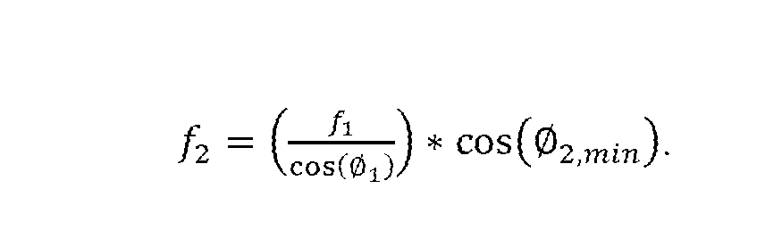
- the second angle (Q 2 ) has a minimum value determined by the equation:
- the second flute pitch if 2 ) relative to the first flute pitch (/ ⁇ ) is determined by the equation:
- the first corrugated media sheet has a third section of a plurality of flutes.
- the flutes of the third section of a plurality of flutes extending at a third angle (Q3) relative to the reference line.
- the third angle is different than the first and second angles
- the flutes of the first section of a plurality of flutes have a positive slope relative to the reference line and the flutes of the third section of a plurality of flutes have a negative slope relative to the reference line.
- the flutes of the second section of a plurality of flutes have a positive slope relative to the reference line.
- flutes of the first section are connected to flutes of the third section forming a continuous flute having a bend where the flutes of the first section are connected to a flutes of the third section.
- the reference line is parallel to a first side of the first sheet and a first side of the second sheet.
- the first side of the first sheet being parallel to the first side of the second sheet.
- the first sheet has first, second, and third sides.
- the first side extends between the second and third sides and in perpendicular relation to the second and third sides.
- the second and third sides are parallel.
- the second sheet has first, second, and third sides.
- the first side extends between the second and third sides and in perpendicular relation to the second and third sides.
- the second and third sides are parallel.
- the reference line is parallel to the first side of the first sheet and parallel to the first side of the second sheet.
- the flutes of the first section of a plurality of flutes extend in parallel relation to one another.
- the flutes of the second section of a plurality of flutes extend in parallel relation to one another.
- the third angle is different than the first angle in that a slope of the flutes of the first section of a plurality of flutes relative to the reference line is positive and a slope of the flutes of the third section of a plurality of flutes is negative relative to the reference line.
- the third angle (Q 3 ) is different than the first angle (qi) in that the magnitude of the third angle (Q 3 ) is greater than a magnitude of the first angle (qi). Both the first and third angles (qi, qi) are acute angles.
- the first sheet includes a fourth side parallel to the first side of the first sheet.
- the second sheet has a fourth side parallel to the first side of the second sheet.
- the fourth sides providing a cooling fluid inlet.
- the second sides provides an air inlet.
- the third side is an air outlet.
- the flutes of the first section of flutes have an upward directed component extending against gravity when moving in a direction extending towards the third side from the second side.
- the flutes of the second section of flutes having an upward directed component extending against gravity when moving in a direction extending towards the third side from the second side.
- the flutes of the third section have a downward directed component extending with gravity when moving in a direction extending towards the third side from the second side.
- the flutes of the third section begin at the second side and do not extend to the third side.
- the flutes of the first section begin offset from the second side and end at the third side.
- the first section of a plurality of llutes are adjacent a first portion of the second section of a plurality of flutes and the third section of a plurality of flutes are adjacent a second portion of the second section of a plurality of flutes, e.g. when the first and second sheets are stacked.
- a plurality of first corrugated media sheets and a plurality of second corrugated media sheet the first and second corrugated media sheets altematingly stacked between first and second corrugated media sheets.
- the bends are positioned between the second and third sides and form an axis that is generally perpendicular to the reference line.
- the axis is positioned closer to the outlet side than the inlet side
- an evaporative cooling system in another example, includes an enclosure having a cooling fluid supply, an air inlet, and an air outlet.
- the system includes an evaporative cooling pack as outlined above positioned within the enclosure between the air inlet and the air outlet.
- the flutes of the first section of a plurality of flutes and the flutes of the second section of a plurality of flutes oriented such that air exiting the evaporative cooling fluid has an upward extending orientation.
- the cooling fluid supply is positioned such that cooling fluid flows through the evaporative cooling pack vertically downward due to gravity.
- FIG. 1 is a schematic representation of nested sheets of an evaporative cooling pack
- FIG. 2 is a schematic representation of sheets of an evaporative cooling pack that are not nested
- FIG. 3 is a schematic illustration of a gas turbine system that includes an evaporative cooling system according to an example of the disclosure
- FIG. 4 is a schematic illustration of a side of an evaporative cooling pack according to the present disclosure
- FIG. 5 is a simplified illustration of a first sheet of the evaporative cooling pack of FIG. 4;
- FIG. 6 is a simplified illustration of a second sheet of the evaporative cooling pack of FIG. 4.
- FIG. 7 is a simplified schematic illustration of the first and second sheets of FIGS. 5 and 6 stacked to show the relative orientations of the flutes of the first and second sheets.
- FIG. 3 is a schematic illustration of a gas turbine system 100 that includes an air intake 102 that supplies air to the gas turbine 104.
- the air intake 102 includes an enclosure 105 that has an air inlet 106 and an air outlet 108.
- Air 109 that is combusted within the gas turbine 104 enters through the inlet 106 and exits through outlet 108.
- An evaporative cooling pack 110 is located within the enclosure 105 between the air inlet 106 and air outlet 108.
- a cooling fluid supply 112 is located within the enclosure 105 to provide cooling fluid 114 to the evaporative cooling pack 110.
- the cooling fluid supply 112 is located vertically above the evaporative cooling pack 110 and the cooling fluid 114 flow's vertically downward through the evaporative cooling pack 110.
- the air 109 flow's laterally through the evaporative cooling pack 110 in a crosswise orientation relative to the flow' of cooling fluid 114.
- the cooling fluid supply 112 may have nozzles spread across the top of the evaporative cooling pack 110.
- the cooling fluid 114 flows vertically downward to maintain the evaporative cooling pack 110 moist so that the air 109 flowing through the evaporative cooling pack 110 can interact with the cooling fluid 114 and transfer heat to the cooling fluid 114.
- side 120 of the evaporative cooling pack 110 forms an inlet side w'here the air 109 enters the evaporative cooling pack 110.
- Opposed side 122 forms an outlet side w'here air 109 exits the evaporative cooling pack 110.
- Side 124 foims the vertical top of the evaporative cooling pack 110 and forms a cooling fluid inlet. Any cooling fluid 114 that is not evaporated will exit the evaporative cooling pack 110 through side 126 which forms the vertical bottom of the evaporative cooling pack 110 and forms a cooling fluid outlet.
- the evaporative cooling pack 110 is rectangular such that sides 120, 122 are parallel to one another and perpendicular to sides 124, 126, which are also parallel to one another.
- the evaporative cooling pack 110 is formed from a plurality of layers of corrugated sheets.
- FIG. 4 illustrates a side view of a evaporative cooling pack 110 in simplified schematic form illustrating a plurality of sheets stacked adjacent one another.
- the peaks and valleys of the sheets 130, 132 form flutes in each sheet 130, 132.
- the flutes in adjacent sheets 130, 132 combine to form flow passages 134 for air to flow through as it is cooled.
- FIG. 5 is a simplified illustration of an example of a first sheet 130 while FIG. 6 is a simplified illustration of an example of a second sheet 132.
- solid lines represent peaks while dashed lines represent valleys between adjacent peaks.
- the sheets 130, 132 are rectangular in shape with each first sheet 130 having first side 136, second side 137, third side 138 and fourth side 139.
- the first and fourth sides 136, 139 being parallel.
- the second and third sides 137, 138 being parallel.
- the first and fourth sides 136, 139 being perpendicular to the second and third sides 137, 138.
- Each second sheet 132 has first side 140, second side 141, third side 142 and fourth side 143.
- the first and fourth sides 140, 143 being parallel.
- the second and third sides 141 , 142 being parallel.
- the first and fourth sides 140, 143 being perpendicular to the second and third sides 141, 142.
- the first sides 136, 140 are adjacent one another
- the second sides 137, 141 are adjacent one another
- the third sides 138, 142 are adjacent one another
- the fourth sides 139, 143 are adjacent one another such that the resulting evaporative cooling pack 110 is a generally rectangular prism.
- the second sides 137, 141 form the air inlet into the evaporative cooling pack 110
- the third sides 138, 142 form the air outlet from the evaporative cooling pack 110 and, when used in a system as illustrated in FIG. 3, the fourth sides 139, 143 from the cooling fluid inlet/receiving end of the evaporative cooling pack 110.
- the peaks and valleys 150 (solid lines), 152 (dashed lines) form flutes 154 that extend between the second and third sides 137, 138.
- the first sheet 130 includes a first section of flutes 156 and a third section of flutes 158.
- a portion of the flute 154 is formed by the first section of flutes 156 and a portion of the flute is formed by the third section of flutes 158.
- the portion of the flute 154 formed in the first section of flutes 156 has a first angle qi (also referred to as a first flute angle) formed between a reference line, e.g. first side 136 while the portion of the flute 154 formed in the third section of flutes 158 has a third angle Q3 (also referred to as a third flute angle) relative to the reference line, again, e.g. first side 136.
- first angle qi also referred to as a first flute angle
- Q3 also referred to as a third flute angle
- the first and third angles qi, 0 3 are different angles. In this example, the angles are different both in magnitude and slope when viewed moving from the second side 137 to the third side 138.
- Third angle Q3 has a larger magnitude than first angle qi.
- the portion of flute 154 in the first section of flutes 156 has a positive slope relative to first side 136. More particularly, it extends vertically upward when moving laterally in a direction extending from the inlet side towards the outlet side while the portion of flute 154 in the third section of flutes 158 has a negative slope relative to first side 136 when moving in the same direction from the second side 137 to the third side 138. More particularly, it extends vertically downward when moving laterally from the inlet side towards the outlet side.
- the first and third angles qi, Q3 are both angles relative to first side 136.
- the portion of Ante 154 within the first section of flutes 156 directs air flow generally vertically against gravity while the portion of flute 154 within the third section of flutes 158 directs air flow generally vertically with gravity.
- the air flow also has a lateral component as the air flows from the inlet side to the outlet side (e.g. from second side 137 to third side 138).
- the difference in angles qi, 0 3 create a bend 160 in each flute 154 when moving from the inlet side, e.g. second side 137 to the outlet side, e.g. third side 138.
- the bends 160 of adjacent flutes generally defines an axis 162 that is generally parallel to second and third sides 137, 138 and generally perpendicular to first and fourth sides 136, 139.
- both portions of each flute 154 extend at non-parallel, nonperpendicular angles to all of the sides 136-139 of the first sheet.
- the portion of the flute 154 within the first section of flutes 156 has a pitch// that is measured generally perpendicular to the extension of the flute 154 within first section of flutes 156.
- all of the portions of the flutes within the first section of flutes 156 are parallel to one another.
- the portions of the flutes 154 within the third section 158 may or may not be parallel to one another.
- first section of flutes 156 has a depth d measured parallel to the reference line, e.g. first side 136.
- depth d is measured between axis 162 and third side 138.
- FIG. 6 illustrates the second sheet 132.
- the second sheet 132 is corrugated and has peaks and valleys 172, 170 illustrated by dash-dot and dotted lines, respectively. Again, the peaks and valleys 172, 170 define flutes 174 that form portions of the air passages through the evaporative cooling pack 110, when stacked with the first sheets 130.
- the flutes 174 are substantially linear their entire extension when moving from second side 141 towards third side 142.
- the entire sheet 132 forms a second section of flutes 178.
- the second section of flutes 178 has a second angle 0 2 relative to the reference line, e.g. first side 140.
- the second angle 02 has a different magnitude than first angle 0i. This is particularly true as both the first and second angles qi, (h have a positive slope relative to the reference line. If the angles were the same, then nesting would be highly probable between first and second sections 156, 178 when stacked to form evaporative cooling pack 110.
- both the first and third sections 156, 158 of the first sheet 130 will be adjacent to corresponding portions of the second section 178 of the second sheet 132.
- the third section 158 has a negative slope and the second section 178 has a positive slope, nesting is unlikely as between those sections.
- the peaks 150 of the first section of flutes 156 of the first sheet 130 will cross/intersect one or more valleys 170 of the second section of flutes 178 of the second sheet 132. This crossing/intersecting therebetween prevents the nesting. Again, this assumes that the second sheet 132 is located on top of the first sheet 130. Alternatively, when the first sheet 130 is on top of the second sheet 132, the valleys 152 of the first section of flutes 156 of the first sheet 130 will cross/intersect one or more peaks 172 of the second section of flutes 178 of the second sheet.
- the intersection of the corresponding peaks 150/valleys 170 occurs in two locations such as proximate axis 162 and proximate the third sides 138, 142 as illustrated in FIG. 7.
- the valleys 170 of the second sheet that intersect at two locations actually intersects two separate peaks 150 of the first sheet. More particularly, a given valley 170 of the second sheet intersects a first peak 150 (e.g adjacent axis 162) and then also intersects a second peak 150 (e.g. adjacent sides 138/142).
- the combinations of the first, second and third angles 0i, 0 2 , 0 3 can control air flow through the evaporative cooling pack and thus how quickly the cooling fluid evaporates. It is desired to keep substantially the entire vertical extent of the evaporative cooling pack 110 moist so that air flowing through all of the flutes at all vertical positions is exposed to the cooling effect of the evaporative cooling pack 110.
Landscapes
- Engineering & Computer Science (AREA)
- Chemical & Material Sciences (AREA)
- Combustion & Propulsion (AREA)
- Mechanical Engineering (AREA)
- General Engineering & Computer Science (AREA)
- Heat-Exchange Devices With Radiators And Conduit Assemblies (AREA)
- Turbine Rotor Nozzle Sealing (AREA)
- Respiratory Apparatuses And Protective Means (AREA)
Abstract
Description


Claims

Priority Applications (5)
| Application Number | Priority Date | Filing Date | Title |
|---|---|---|---|
| CN202180030006.1A CN115885097B (en) | 2020-04-23 | 2021-04-23 | Evaporative cooling pack with co-directional concavities designed to prevent nesting |
| JP2022561096A JP7745566B2 (en) | 2020-04-23 | 2021-04-23 | Evaporative cooling packs designed so that grooves in the same direction do not nest together |
| EP21796094.7A EP4139565A4 (en) | 2020-04-23 | 2021-04-23 | EVAPORATIVE COOLING PACK WITH GROOVES IN THE SAME DIRECTION TO PREVENT NESTING |
| US17/959,391 US12025056B2 (en) | 2020-04-23 | 2022-10-04 | Evaporative cooling pack with same direction flutes designed to prevent nesting |
| SA522440962A SA522440962B1 (en) | 2020-04-23 | 2022-10-18 | Evaporative Cooling Pack With Same Direction Flutes Designed to Prevent Nesting |
Applications Claiming Priority (2)
| Application Number | Priority Date | Filing Date | Title |
|---|---|---|---|
| US202063014233P | 2020-04-23 | 2020-04-23 | |
| US63/014,233 | 2020-04-23 |
Related Child Applications (1)
| Application Number | Title | Priority Date | Filing Date |
|---|---|---|---|
| US17/959,391 Continuation US12025056B2 (en) | 2020-04-23 | 2022-10-04 | Evaporative cooling pack with same direction flutes designed to prevent nesting |
Publications (2)
| Publication Number | Publication Date |
|---|---|
| WO2021222021A2 true WO2021222021A2 (en) | 2021-11-04 |
| WO2021222021A3 WO2021222021A3 (en) | 2022-02-03 |
Family
ID=78373860
Family Applications (1)
| Application Number | Title | Priority Date | Filing Date |
|---|---|---|---|
| PCT/US2021/028855 Ceased WO2021222021A2 (en) | 2020-04-23 | 2021-04-23 | Evaporative cooling pack with same direction flutes designed to prevent nesting |
Country Status (6)
| Country | Link |
|---|---|
| US (1) | US12025056B2 (en) |
| EP (1) | EP4139565A4 (en) |
| JP (1) | JP7745566B2 (en) |
| CN (1) | CN115885097B (en) |
| SA (1) | SA522440962B1 (en) |
| WO (1) | WO2021222021A2 (en) |
Citations (4)
| Publication number | Priority date | Publication date | Assignee | Title |
|---|---|---|---|---|
| US20030150234A1 (en) | 2002-01-09 | 2003-08-14 | Tadahiro Ohmi | Air cooling device and air cooling method |
| JP2009180433A (en) | 2008-01-31 | 2009-08-13 | Tohoku Univ | Wet desiccant air conditioner |
| US20170276386A1 (en) | 2016-03-28 | 2017-09-28 | General Electric Company | Synthetic media pads for an evaporative cooler and method for evaporative cooling |
| US20190120509A1 (en) | 2017-10-20 | 2019-04-25 | Seeley International Pty Ltd | Evaporative media pad with reduced internal spacing |
Family Cites Families (30)
| Publication number | Priority date | Publication date | Assignee | Title |
|---|---|---|---|---|
| SE307963B (en) * | 1962-06-27 | 1969-01-27 | Munters C | |
| SE302778B (en) * | 1963-07-04 | 1968-08-05 | C Munters | |
| FR1380254A (en) | 1964-01-23 | 1964-11-27 | Gen Motors Corp | Heat transfer device for regenerative heat exchanger |
| SE321492B (en) * | 1968-03-12 | 1970-03-09 | Alfa Laval Ab | |
| SU1030619A1 (en) * | 1982-04-08 | 1983-07-23 | Всесоюзный научно-исследовательский и проектно-конструкторский институт металлургической теплотехники цветной металлургии и огнеупоров | Regenerative heat exchanger |
| US5143658A (en) * | 1991-09-23 | 1992-09-01 | Munters Corporation | Alternating sheet evaporative cooling pad |
| US5320651A (en) * | 1993-06-28 | 1994-06-14 | Munters Corporation | Cross-flow film fill media with intergral drift eliminator |
| AUPM777294A0 (en) * | 1994-08-30 | 1994-09-22 | William Allen Trusts Pty Ltd | Spaced evaporative wicks within an air cooler |
| EP0773412B1 (en) * | 1995-11-07 | 2003-12-17 | Kabushiki Kaisha Seibu Giken | A method and a device for refrigeration of fluid and desiccative refrigeration of gas |
| US6260830B1 (en) * | 1998-11-25 | 2001-07-17 | Baltimore Aircoil Company, Inc. | Film fill-pack for inducement of spiraling gas flow in heat and mass transfer contact apparatus with self-spacing fill-sheets |
| US6282915B1 (en) * | 2000-01-24 | 2001-09-04 | Indirex | Evaporative cooler |
| CN2624108Y (en) | 2003-05-07 | 2004-07-07 | 王吉军 | Evaporation cooling and humidification block |
| TR200704377T1 (en) | 2005-01-11 | 2007-08-21 | F F Seeley Nominees Pty Ltd | Methods and materials for the development of vaporised heat exchangers. |
| CN101487671A (en) * | 2005-04-22 | 2009-07-22 | 株式会社电装 | Heat exchanger |
| US20090294548A1 (en) * | 2006-02-10 | 2009-12-03 | Stephan Geiger | Air Humidifier and Evaporation Mat Contained Therein |
| US7625419B2 (en) * | 2006-05-10 | 2009-12-01 | Donaldson Company, Inc. | Air filter arrangement; assembly; and, methods |
| FR2931542A1 (en) | 2008-05-22 | 2009-11-27 | Valeo Systemes Thermiques | HEAT EXCHANGER WITH PLATES, IN PARTICULAR FOR MOTOR VEHICLES |
| US8397523B2 (en) * | 2008-05-30 | 2013-03-19 | Sanyo Electric Co., Ltd. | Electrolytic water generating device, air filtering system, air conditioning and filtering apparatus, and air conditioning and filtering system |
| WO2013113362A1 (en) * | 2012-01-30 | 2013-08-08 | A-Heat Allied Heat Exchange Technology Ag | Heat exchanger |
| US9850816B2 (en) * | 2013-11-04 | 2017-12-26 | General Electric Company | Gas turbine inlet system and related method for cooling gas turbine inlet air |
| US20150377569A1 (en) | 2014-06-30 | 2015-12-31 | General Electric Company | Media Pads for Gas Turbine |
| CN104121792B (en) * | 2014-07-31 | 2016-08-24 | 叶立英 | Indirect evaporating-cooling core body |
| US10767561B2 (en) * | 2014-10-10 | 2020-09-08 | Stellar Energy Americas, Inc. | Method and apparatus for cooling the ambient air at the inlet of gas combustion turbine generators |
| US9551282B2 (en) | 2014-10-17 | 2017-01-24 | General Electric Company | Media pads with mist elimination features |
| EP3144485A1 (en) * | 2015-09-16 | 2017-03-22 | Siemens Aktiengesellschaft | Turbomachine component with cooling features and a method for manufacturing such a turbomachine component |
| US20190011193A1 (en) * | 2016-01-13 | 2019-01-10 | Hisaka Works, Ltd. | Plate heat exchanger |
| US20180266317A1 (en) | 2017-03-20 | 2018-09-20 | General Electric Company | Evaporative cooling medium with micro-channels |
| US10260421B2 (en) * | 2017-03-20 | 2019-04-16 | General Electric Company | Fibrous media drift eliminator |
| US10495000B2 (en) * | 2017-03-20 | 2019-12-03 | General Electric Company | Contoured evaporative cooling medium |
| US11493289B1 (en) * | 2021-06-04 | 2022-11-08 | Grahame Ernest Maisey | Wettable media and method of making the same |
-
2021
- 2021-04-23 JP JP2022561096A patent/JP7745566B2/en active Active
- 2021-04-23 EP EP21796094.7A patent/EP4139565A4/en active Pending
- 2021-04-23 WO PCT/US2021/028855 patent/WO2021222021A2/en not_active Ceased
- 2021-04-23 CN CN202180030006.1A patent/CN115885097B/en active Active
-
2022
- 2022-10-04 US US17/959,391 patent/US12025056B2/en active Active
- 2022-10-18 SA SA522440962A patent/SA522440962B1/en unknown
Patent Citations (4)
| Publication number | Priority date | Publication date | Assignee | Title |
|---|---|---|---|---|
| US20030150234A1 (en) | 2002-01-09 | 2003-08-14 | Tadahiro Ohmi | Air cooling device and air cooling method |
| JP2009180433A (en) | 2008-01-31 | 2009-08-13 | Tohoku Univ | Wet desiccant air conditioner |
| US20170276386A1 (en) | 2016-03-28 | 2017-09-28 | General Electric Company | Synthetic media pads for an evaporative cooler and method for evaporative cooling |
| US20190120509A1 (en) | 2017-10-20 | 2019-04-25 | Seeley International Pty Ltd | Evaporative media pad with reduced internal spacing |
Non-Patent Citations (1)
| Title |
|---|
| See also references of EP4139565A4 |
Also Published As
| Publication number | Publication date |
|---|---|
| JP2023523161A (en) | 2023-06-02 |
| WO2021222021A3 (en) | 2022-02-03 |
| EP4139565A2 (en) | 2023-03-01 |
| US20230040732A1 (en) | 2023-02-09 |
| CN115885097A (en) | 2023-03-31 |
| JP7745566B2 (en) | 2025-09-29 |
| EP4139565A4 (en) | 2024-05-01 |
| CN115885097B (en) | 2025-12-16 |
| SA522440962B1 (en) | 2024-08-28 |
| US12025056B2 (en) | 2024-07-02 |
Similar Documents
| Publication | Publication Date | Title |
|---|---|---|
| US7614443B2 (en) | Heat exchanger tube | |
| US20150241142A1 (en) | Heat Exchanger Insert | |
| US8844504B2 (en) | Heat exchanger and method of manufacturing the same | |
| US9714794B2 (en) | Heat exchanger tube having fins with varying louver inclination angle | |
| US20080011464A1 (en) | Exhaust gas heat exchanger | |
| US6820682B2 (en) | Heat exchanger | |
| US20100071675A1 (en) | Flow channel, heat exchanger, exhaust gas recirculation system, charge air supply system, use of a heat exchanger | |
| US20080087410A1 (en) | Heat exchanger | |
| US6675878B2 (en) | Angled turbulator for use in heat exchangers | |
| KR20080108545A (en) | Automotive Heat Exchanger | |
| US20130153184A1 (en) | Heat exchanger | |
| US20130263829A1 (en) | Gas-to-liquid heat exchanger | |
| JP2014535030A (en) | Wave fin | |
| JP2001263967A (en) | Exhaust heat exchanger | |
| US20090087604A1 (en) | Extruded tube for use in heat exchanger | |
| US20070056719A1 (en) | Heat exchanger for cooling | |
| US12025056B2 (en) | Evaporative cooling pack with same direction flutes designed to prevent nesting | |
| JP6550177B1 (en) | Heat exchanger | |
| EP2530420A2 (en) | Fin and tube heat exchanger | |
| JP6481275B2 (en) | Corrugated fin heat exchanger | |
| US20110308228A1 (en) | Fin and Tube Heat Exchanger | |
| JP2007255857A (en) | Evaporator | |
| JP2012017921A (en) | Heat exchanger and intake air cooling system of engine using the same | |
| JP2012067955A (en) | Heat exchanger and engine intake air cooling device using the same | |
| WO2024053300A1 (en) | Heat exchanger |
Legal Events
| Date | Code | Title | Description |
|---|---|---|---|
| 121 | Ep: the epo has been informed by wipo that ep was designated in this application |
Ref document number: 21796094 Country of ref document: EP Kind code of ref document: A2 |
|
| ENP | Entry into the national phase |
Ref document number: 2022561096 Country of ref document: JP Kind code of ref document: A |
|
| NENP | Non-entry into the national phase |
Ref country code: DE |
|
| ENP | Entry into the national phase |
Ref document number: 2021796094 Country of ref document: EP Effective date: 20221123 |
|
| WWE | Wipo information: entry into national phase |
Ref document number: 522440962 Country of ref document: SA |
|
| WWE | Wipo information: entry into national phase |
Ref document number: 522440962 Country of ref document: SA |
|
| WWG | Wipo information: grant in national office |
Ref document number: 522440962 Country of ref document: SA |