WO2021225084A1 - 損傷評価装置、方法及びプログラム - Google Patents
損傷評価装置、方法及びプログラム Download PDFInfo
- Publication number
- WO2021225084A1 WO2021225084A1 PCT/JP2021/016627 JP2021016627W WO2021225084A1 WO 2021225084 A1 WO2021225084 A1 WO 2021225084A1 JP 2021016627 W JP2021016627 W JP 2021016627W WO 2021225084 A1 WO2021225084 A1 WO 2021225084A1
- Authority
- WO
- WIPO (PCT)
- Prior art keywords
- damage
- specific
- image
- cracks
- crack
- Prior art date
- Legal status (The legal status is an assumption and is not a legal conclusion. Google has not performed a legal analysis and makes no representation as to the accuracy of the status listed.)
- Ceased
Links
Images







Classifications
-
- G—PHYSICS
- G06—COMPUTING OR CALCULATING; COUNTING
- G06T—IMAGE DATA PROCESSING OR GENERATION, IN GENERAL
- G06T7/00—Image analysis
- G06T7/0002—Inspection of images, e.g. flaw detection
-
- G—PHYSICS
- G06—COMPUTING OR CALCULATING; COUNTING
- G06T—IMAGE DATA PROCESSING OR GENERATION, IN GENERAL
- G06T7/00—Image analysis
- G06T7/0002—Inspection of images, e.g. flaw detection
- G06T7/0004—Industrial image inspection
- G06T7/001—Industrial image inspection using an image reference approach
-
- G—PHYSICS
- G06—COMPUTING OR CALCULATING; COUNTING
- G06T—IMAGE DATA PROCESSING OR GENERATION, IN GENERAL
- G06T11/00—Two-dimensional [2D] image generation
- G06T11/60—Creating or editing images; Combining images with text
-
- G—PHYSICS
- G06—COMPUTING OR CALCULATING; COUNTING
- G06T—IMAGE DATA PROCESSING OR GENERATION, IN GENERAL
- G06T7/00—Image analysis
- G06T7/60—Analysis of geometric attributes
-
- G—PHYSICS
- G06—COMPUTING OR CALCULATING; COUNTING
- G06V—IMAGE OR VIDEO RECOGNITION OR UNDERSTANDING
- G06V10/00—Arrangements for image or video recognition or understanding
- G06V10/98—Detection or correction of errors, e.g. by rescanning the pattern or by human intervention; Evaluation of the quality of the acquired patterns
- G06V10/993—Evaluation of the quality of the acquired pattern
-
- G—PHYSICS
- G01—MEASURING; TESTING
- G01N—INVESTIGATING OR ANALYSING MATERIALS BY DETERMINING THEIR CHEMICAL OR PHYSICAL PROPERTIES
- G01N21/00—Investigating or analysing materials by the use of optical means, i.e. using sub-millimetre waves, infrared, visible or ultraviolet light
- G01N21/84—Systems specially adapted for particular applications
- G01N21/88—Investigating the presence of flaws or contamination
- G01N21/8851—Scan or image signal processing specially adapted therefor, e.g. for scan signal adjustment, for detecting different kinds of defects, for compensating for structures, markings, edges
- G01N2021/8883—Scan or image signal processing specially adapted therefor, e.g. for scan signal adjustment, for detecting different kinds of defects, for compensating for structures, markings, edges involving the calculation of gauges, generating models
-
- G—PHYSICS
- G06—COMPUTING OR CALCULATING; COUNTING
- G06T—IMAGE DATA PROCESSING OR GENERATION, IN GENERAL
- G06T2207/00—Indexing scheme for image analysis or image enhancement
- G06T2207/10—Image acquisition modality
- G06T2207/10032—Satellite or aerial image; Remote sensing
-
- G—PHYSICS
- G06—COMPUTING OR CALCULATING; COUNTING
- G06T—IMAGE DATA PROCESSING OR GENERATION, IN GENERAL
- G06T2207/00—Indexing scheme for image analysis or image enhancement
- G06T2207/20—Special algorithmic details
- G06T2207/20081—Training; Learning
-
- G—PHYSICS
- G06—COMPUTING OR CALCULATING; COUNTING
- G06T—IMAGE DATA PROCESSING OR GENERATION, IN GENERAL
- G06T2207/00—Indexing scheme for image analysis or image enhancement
- G06T2207/20—Special algorithmic details
- G06T2207/20084—Artificial neural networks [ANN]
-
- G—PHYSICS
- G06—COMPUTING OR CALCULATING; COUNTING
- G06T—IMAGE DATA PROCESSING OR GENERATION, IN GENERAL
- G06T2207/00—Indexing scheme for image analysis or image enhancement
- G06T2207/20—Special algorithmic details
- G06T2207/20092—Interactive image processing based on input by user
- G06T2207/20096—Interactive definition of curve of interest
-
- G—PHYSICS
- G06—COMPUTING OR CALCULATING; COUNTING
- G06T—IMAGE DATA PROCESSING OR GENERATION, IN GENERAL
- G06T2207/00—Indexing scheme for image analysis or image enhancement
- G06T2207/30—Subject of image; Context of image processing
- G06T2207/30108—Industrial image inspection
- G06T2207/30132—Masonry; Concrete
-
- G—PHYSICS
- G06—COMPUTING OR CALCULATING; COUNTING
- G06T—IMAGE DATA PROCESSING OR GENERATION, IN GENERAL
- G06T2207/00—Indexing scheme for image analysis or image enhancement
- G06T2207/30—Subject of image; Context of image processing
- G06T2207/30181—Earth observation
- G06T2207/30184—Infrastructure
Definitions
- the present invention relates to a damage evaluation device, a method and a program, and particularly relates to a technique for evaluating a structure damage that occurs in connection with the construction of the structure.
- Non-Patent Document 1 it has been proposed to visually evaluate defects that occur in the surface layer of a newly constructed structure and utilize them for validation of construction methods and improvement of construction methods.
- Patent Document 1 an image showing the surface of a structure is image-analyzed to detect cracks on the surface of the structure, and the feature amounts of the detected cracks (crack direction, length, width, edge strength, and edge strength, and (Edge density, etc.) is detected, each crack is grouped based on the detected feature amount, and when displaying a crack image filled with cracks, the crack image is displayed using a different line type or color for each group.
- the image processing method is described.
- the tunnel lining surface image acquired in chronological order can be compared, and the tunnel lining surface image of this time can be corrected so that even a crack changed by about several mm can be recognized.
- the image correction method is described.
- the tunnel lining surface image correction method described in Patent Document 2 detects a position-invariant installation object or joint on the tunnel lining surface, performs image processing to match the positions of the installation object or joint between different time-series images, and performs image processing. By generating a tunnel lining surface image whose position is normalized, the tunnel lining surface image used for time-series management of deformation is corrected.
- Patent Document 1 describes that cracks on the surface of a structure are grouped based on the detected features of the cracks, but there is no description of selecting damages that occur in connection with the construction of the structure.
- Patent Document 2 describes that joints are detected together with cracks in a concrete structure, but the joints whose positions do not change are image processed to match the previous tunnel lining surface image with the current tunnel lining surface image ( It is used to perform affine transformation), not to screen for damage.
- the present invention has been made in view of such circumstances, and provides a damage evaluation device, method and program capable of automatically evaluating damage to the surface layer of a structure that occurs in connection with the construction of the structure.
- the purpose is a damage evaluation device, method and program capable of automatically evaluating damage to the surface layer of a structure that occurs in connection with the construction of the structure.
- the invention according to the first aspect is a damage evaluation device for a structure provided with a processor, wherein the processor acquires an image of the structure and obtains an image.
- Damage detection processing that detects damage to the structure based on it
- feature area detection processing that detects the feature area of the structure related to the construction of the structure based on the acquired image
- the detected structure among the detected damages A sorting process for selecting specific damages related to the characteristic area and an information output processing for outputting information on the selected specific damages are performed.
- the specific damages related to the structure feature area related to the construction of the structure are automatically selected. Since the information on the selected specific damage is output, it is possible to automatically evaluate the damage on the surface layer of the structure that occurs in connection with the construction of the structure, and it is possible to verify the validity of the construction method and improve the construction method. It can be utilized.
- the damage detection process is executed by a first trained model that outputs an area of each damage as a recognition result for each damage of the structure when an image is input. ..
- the damage to the structure is a crack in the structure
- the specific damage is a specific crack generated due to the construction of the structure among the cracks in the structure.
- Specific cracks include, for example, sinking cracks and crescent cracks that occur in the surface layer of a concrete structure.
- the feature region detection process is executed by the second trained model that outputs the structure feature region as a recognition result when an image is input.
- the structure feature region is a region showing a construction mark related to a specific crack which is a specific damage generated due to the construction of the structure.
- Construction marks related to specific cracks are, for example, P-concrete marks, joints, and joints on the surface layer of a concrete structure.
- the sorting process sorts damage that comes into contact with the structure feature region or damage that overlaps with the structure feature region as specific damage.
- the sorting process includes an expansion process for expanding the size of the structure feature region, and the damage or the expanded structure in contact with the expanded structure feature region. It is preferable to select the damage that overlaps the feature area as a specific damage.
- the rate or amount of expansion of the size of the structure feature region may be a preset value or a value appropriately set by the user.
- the processor performs a size specifying process for specifying the size of the specific damage.
- the damage to the structure includes a crack in the structure, and the specific damage is a specific crack generated due to the construction of the structure among the cracks in the structure.
- the relative length between the length on the image of the specific crack and the length on the image of the structure feature region can be calculated, and the calculated relative length can be set as the size of the specific damage.
- the damage to the structure includes a crack in the structure
- the specific damage is a specific crack generated due to the construction of the structure among the cracks in the structure. Therefore, in the size specifying process, it is preferable to calculate the actual size of the specific damage based on the length on the image of the specific crack, the length on the image of the structure feature area, and the actual size of the structure feature area.
- the damage to the structure includes a crack in the structure, and the specific damage is a specific crack generated due to the construction of the structure among the cracks in the structure.
- the image captures a structure with a scale reference whose actual dimensions are known, and the sizing process is the actual size of the specific damage based on the length on the image of the specific crack and the length on the image of the scale reference. It is preferable to calculate the size.
- the damage to the structure includes a crack in the structure
- the specific damage is a specific crack generated due to the construction of the structure among the cracks in the structure. Therefore, in the size specifying process, it is preferable to calculate the actual size of the specific damage based on the length of the specific crack on the image, the shooting conditions of the camera that captured the image, and the camera information.
- the shooting conditions of the camera include, for example, the distance between the camera and the specific crack
- the camera information includes, for example, the focal length, the size of the image sensor, the number of pixels, or the pixel pitch.
- the information output process outputs each specific damage in an identifiable manner according to the attribute of the specific damage.
- Specific damage attributes include damage length, width, area, and so on. Further, it is preferable that each specific damage is color-coded according to the attribute of the specific damage so that the specific damage can be identified by the difference in line type or the like.
- the information output process outputs the structural feature region corresponding to the specific damage in an identifiable manner according to the attribute of the specific damage.
- the processor calculates the ratio between the total number of the structure feature regions and the number of the structure feature regions corresponding to the specific damage, and the information output process calculates the calculated ratio. It is preferable to output.
- the processor gives an editing instruction of at least one of the detected damage detection result and the detected structure feature region detection result from the operation unit operated by the user. It is preferable to perform an editing instruction receiving process for receiving and an editing process for editing the detection result according to the received editing instruction.
- the information output process outputs information on specific damage to a display and displays it, or saves it as a file in a memory.
- the specific damage information includes damage identification information, damage type and size items, and a damage quantity table in which information corresponding to each item is described for each specific damage. Is preferably included.
- the invention according to the nineteenth aspect is a damage evaluation method for evaluating damage to a structure by a processor, and each process of the processor includes a step of acquiring an image of the structure and a structure based on the acquired image.
- the step of detecting the damage of the structure, the step of detecting the structure feature area related to the construction of the structure based on the acquired image, and the specific damage related to the detected structure feature area among the detected damages. Includes a step of sorting out and a step of outputting information on the selected specific damage.
- the invention according to the twentieth aspect is a damage evaluation program for causing a computer to execute a method for evaluating damage to a structure, wherein the method is a step of acquiring an image of a structure and a structure based on the acquired image.
- damage to the surface layer of a structure that occurs in connection with the construction of the structure can be automatically evaluated.
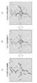
- FIG. 1 is a diagram showing an example of damage to a structure.
- FIG. 2 is a diagram showing an example of a flow from damage detection to selection of specific damage.
- FIG. 3 is a diagram used for explaining a method of selecting whether or not the detected crack is a sinking crack.
- FIG. 4 is a block diagram showing an example of the hardware configuration of the damage evaluation device according to the present invention.
- FIG. 5 is a conceptual diagram showing an embodiment of a damage detection processing unit and a feature area detection processing unit configured by a CPU or the like.
- FIG. 6 is a diagram showing a first display example of an image of a structure to be evaluated and information on specific damage.
- FIG. 7 is a diagram showing a second display example of an image of the structure to be evaluated and information on specific damage.
- FIG. 8 is a diagram showing an example of a display screen in which a color-coded crack image is added to the image shown in FIG. 7 (B).
- FIG. 9 is a diagram showing another example of specific damage related to the structural feature area related to the construction of the structure.
- FIG. 10 is a diagram showing still another example of specific damage related to the structural feature area related to the construction of the structure.
- FIG. 11 is a diagram showing another example of the flow from damage detection to selection of specific damage.
- FIG. 12 is a damage diagram including information on cracks.
- FIG. 13 is a chart showing an example of a damage quantity table included in the damage detection result.
- FIG. 14 is a diagram showing a method of adding vertices to a polyline along a crack.
- FIG. 15 is a diagram showing a method of removing vertices from a polyline along a crack.
- FIG. 16 is a flowchart showing an embodiment of the damage evaluation method according to the present invention.
- FIG. 1 is a diagram showing an example of damage to a structure
- FIG. 1 (A) shows an original image of a concrete structure having a construction mark of the structure
- FIG. 1 (B) shows crack detection.
- a composite image in which the result (cracked image) is superimposed and displayed on the original image is created.
- the construction trace of the structure in this example is the trace of a plastic cone (hereinafter referred to as "P-con"), and P on FIG. 1 indicates the trace of P-con.
- P-con trace P will be described.
- FIG. 1 (B) show cracks around the P-con trace P.
- the cracks C1 to C3 are represented by a crack image in which the crack region detected from the original image of FIG. 1 (A) is filled with a specific color.
- Cracks C1 to C3 around the P-con trace P are classified as sinking cracks and are one of the cracks generated due to the construction of the structure.
- the sinking crack is a crack caused by restraining the displacement due to sinking or bleeding after the concrete is poured by the formwork separator, the formwork on the surface, or the like.
- One aspect of the present invention detects damage to a structure from an image of the structure, selects damage related to the construction of the structure (specific damage) from the detected damage, and selects specific damage. Information is output. This makes it possible to utilize it for verification of the validity of the construction method of the structure and improvement of the construction method.
- the structural feature region related to the construction of the structure is the region of the P-con trace P
- the specific damages related to the region of the P-con trace are the sinking cracks C1 to C3.
- FIG. 2 is a diagram showing an example of a flow from damage detection to selection of specific damage.
- damage to the structure is detected based on an image of the structure. Cracks may be detected by artificial intelligence (AI) or by an image processing algorithm.
- AI artificial intelligence
- the structure feature region (in this example, the region of the P-con trace P) related to the construction of the structure is detected based on the photographed image of the structure.
- the region of the P-con trace P may be detected by AI or by an image processing algorithm. Further, it may be detected by accepting a manual instruction input by the user.
- the submerged cracks (specific cracks) C1 to C4 related to the region of the P-con trace P were selected, and the selected submerged cracks C1 to C4 were selected. Is color-coded so that it can be distinguished from other cracks, or the line type is changed and output.
- FIG. 3 is a diagram used to explain a method of selecting whether or not the detected crack is a sinking crack.
- FIG. 3A shows the detected cracks C1 to C3 and the P-con trace P, respectively.
- Whether or not the cracks C1 to C3 are sinking cracks related to the region of the P-con trace P can be determined when the cracks C1 to C3 come into contact with the region of the P-con trace P or the region of the P-con trace P. If it overlaps with, it is sorted as a sinking crack.
- the size of the region of the P-con trace P is expanded to the size of the region of the P-con trace P1.
- the expansion process of the region of the P-con trace P expands the region of the P-con trace P at a constant ratio in the radial direction from the center of the circular P-con trace P, or expands the outer shape of the circular P-con trace P to a constant.
- the rate or amount of expansion of the area of the P-con trace P may be a preset value or a value appropriately set by the user.
- the cracks C1 to C3 are all in contact with the region of the P-con trace P1 or overlap with the region of the P-con trace P1, so that the cracks are sorted as sinking cracks.
- the region of the P-con trace is not limited to the case where the detected P-con region is expanded by the expansion process, and a region slightly wider than the original P-con trace region is detected as the P-con trace region. You may.
- the distance between the cracks C1 to C3 and the region of the P-con trace P1 may be calculated, and if the distance is within the threshold value, it may be selected as a sinking crack.
- FIG. 4 is a block diagram showing an example of the hardware configuration of the damage evaluation device according to the present invention.
- the damage evaluation device 10 shown in FIG. 1 a personal computer or a workstation can be used.
- the damage evaluation device 10 of this example mainly includes an image acquisition unit 12, an image database 14, a storage unit 16, an operation unit 18, a CPU (Central Processing Unit) 20, a RAM (Random Access Memory) 22, and a ROM. It is composed of (Read Only Memory) 24 and a display control unit 26.
- the image acquisition unit 12 corresponds to an input / output interface, and in this example, acquires an image or the like of a structure to be evaluated.
- the structure to be evaluated includes, for example, walls, columns, beams of bridges, tunnels, buildings and the like.
- the image acquired by the image acquisition unit 12 is, for example, a drone (unmanned aerial vehicle) equipped with a camera, a robot, or a large number of images (image group) obtained by manually photographing a structure. It is preferable that the image group covers the entire structure and the adjacent images are overlapped.
- the image group acquired by the image acquisition unit 12 is stored in the image database 14.
- the storage unit 16 is a memory composed of a hard disk device, a flash memory, and the like.
- the storage unit 16 contains a CAD (computer-aided design) data indicating a structure, and a file, in addition to an operating system and a damage evaluation program. Information on the damage done is stored.
- the damage information includes damage evaluation results such as damage images and damage diagrams (CAD data).
- the CAD data of the structure to be evaluated if the CAD data exists in advance, it can be used. When the CAD data of the structure does not exist, it can be automatically created based on the image group stored in the image database 14.
- the feature points between the images overlapping each other in the image group are extracted, and the feature points are mounted on the drone based on the extracted feature points. It is possible to estimate the position and orientation of the camera, and to generate a three-dimensional point cloud model in which the three-dimensional position of the feature point is estimated at the same time from the estimation result of the position and orientation of the camera.
- Structure from Motion Structure from Motion
- Structure from Motion that tracks the movement of many feature points from a group of images in which the shooting position of the camera is moved by the drone, and simultaneously estimates the three-dimensional structure (Structure) and camera posture (Motion) of the structure.
- SfM three-dimensional structure
- bundle adjustment an optimization calculation method called bundle adjustment has been developed, and it has become possible to output with high accuracy.
- CAD data of the structure can be generated based on the generated 3D point cloud model.
- the operation unit 18 includes a keyboard, a mouse, and the like that are connected to the computer by wire or wirelessly, and functions as an operation unit that gives normal operation instructions to the computer.
- the operation unit 18 has a structure detected based on an image of the structure. It functions as an operation unit that edits the detection result of damage to an object and the detection result of a structural feature area such as a P-con trace by a user operation. Details such as editing the damage detection result will be described later.
- the CPU 20 reads various programs stored in the storage unit 16 or the ROM 24 or the like, controls each unit in an integrated manner, and detects damage to the structure based on a photographed image of the structure. Damage detection processing and construction of the structure. Feature area detection process to detect the structure feature area related to (P-con trace area, etc.), selection process to select specific damage related to the structure feature area among the detected damages, and selected identification. Performs information output processing, etc. to output damage information.
- the damage detection process for detecting damage based on the captured image of the structure and the feature area detection process for detecting the feature area of the structure can be performed by AI, respectively.
- a trained model by a convolutional neural network can be used.
- CNN convolutional neural network
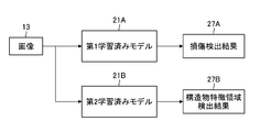
- FIG. 5 is a conceptual diagram showing an embodiment of a damage detection processing unit and a feature area detection processing unit configured by a CPU or the like.
- the damage detection processing unit and the feature area detection processing unit are composed of the first trained model 21A and the second trained model 21B, respectively.
- the first trained model 21A and the second trained model 21B each have an input layer, an intermediate layer, and an output layer, and each layer has a structure in which a plurality of "nodes" are connected by "edges".
- Image 13 of the structure is input to the input layer of CNN.
- the intermediate layer has a plurality of sets including a convolution layer and a pooling layer as one set, and is a portion for extracting features from an image input from an input layer.
- the convolution layer filters nearby nodes in the previous layer (performs a convolution operation using the filter) and acquires a "feature map”.
- the pooling layer reduces the feature map output from the convolution layer to a new feature map.
- the "convolution layer” plays a role of feature extraction such as edge extraction from an image, and the “pooling layer” plays a role of imparting robustness so that the extracted features are not affected by translation or the like.
- the output layer of CNN is the part that outputs the feature map showing the features extracted by the intermediate layer.
- the output layer of the first trained model 21A of this example is inferred, for example, by region classification (segmentation) of the area for each damage of the structure shown in the image in pixel units or in units of several pixels as a group.
- the result (recognition result) is output as the damage detection result 27A
- the output layer of the second trained model 21B of this example is, for example, a structure feature region related to the construction of the structure shown in the image.
- the inference result in which the area is classified in pixel units or in units of a group of several pixels is output as the structure feature area detection result 27B.
- the first trained model 21A is a trained model machine-learned to detect cracks
- the second trained model 21B is a trained model machine-learned to detect P-con traces. be.
- the first trained model 21A and the second trained model 21B may be configured to be composed of one trained model and output a damage detection result 27A and a structure feature region detection result 27B, respectively.
- the CPU 20 is among the damages detected based on the damage detection result 27A and the structure feature region detection result 27B detected by the first trained model 21A and the second trained model 21B, respectively.
- a sorting process is performed to sort out specific damages related to the detected structural feature area.
- sinking cracks specific cracks related to the P-con trace are selected. The selection of sinking cracks can be performed by the method described with reference to FIG. 3, and detailed description thereof will be omitted here.
- the CPU 20 outputs the selected specific damage information to the display unit (display) 30 via the display control unit 26 and displays it, or stores it in the storage unit (memory) 16 as a file. Further, it is preferable that the CPU 20 also outputs the information of the structure feature area to the display unit 30 via the display control unit 26 and displays it, or stores it in the storage unit 16 as a file.
- the RAM 22 is used as a work area of the CPU 20, and is used as a storage unit for temporarily storing the read program and various data.
- the display control unit 26 is a part that creates display data to be displayed on the display unit 30 and outputs the display data to the display unit 30.
- the display unit 30 displays information such as specific damage detected and selected by the CPU 20. It is displayed, and a screen or the like for editing information such as specific damage based on a user operation from the operation unit 18 is displayed on the display unit 30.
- the display unit 30 uses various displays such as a liquid crystal monitor that can be connected to a computer, and displays an image of a structure input from the display control unit 26 as well as information on specific damage detected from the image. It is also used as part of the user interface together with the operation unit 18.
- the processor including the CPU 20 of the damage evaluation device 10 having the above configuration performs each of the above processes by reading the damage evaluation program stored in the storage unit 16 or the ROM 24 and executing the damage evaluation program.
- FIG. 6 is a diagram showing a first display example of an image of a structure to be evaluated and information on specific damage.
- the CPU 20 of the damage evaluation device 10 the damage evaluation program stored in the storage unit 16, the RAM 22 and ROM 24, the display control unit 26, and the like constitute a processor, and the processor performs various processes shown below.
- the processor performs an image acquisition process of acquiring an image of the structure to be evaluated (surface layer of the concrete structure) from the image acquisition unit 12.
- the processor reads the image of the structure to be evaluated from the image database 14.
- the processor acquires a plurality of images and performs image processing for panoramic composition of the plurality of images so that the images in the overlapping regions of the acquired plurality of images match.
- the panoramic composite image to be panoramic composite is preferably an orthographic image projected onto the surface of the concrete structure as shown in FIG. 6 (A).
- a high-resolution image In order to detect cracks of 0.1 mm or less from an image, a high-resolution image is required, so the shooting range of one image becomes small. In order to acquire an image of a structure of a certain size, it is preferable to panoramicly combine a plurality of images, but when a high-resolution camera or a crack detection is required and the crack width is large, one image is used. It may be an image.
- the first trained model 21A Detects cracks based on the input image 13, outputs a damage detection result 27A indicating the detected cracks, and the second trained model 21B detects and detects P-con traces based on the input image 13.
- the structure feature area detection result 27B showing the trace of the P-con is output.
- the processor is related to the structure feature area detection result 27B (P-con trace) of the damage detection results 27A (cracks) based on the damage detection result 27A and the structure feature area detection result 27B.
- the processor performs a size specification process that specifies the size of the specific damage (sinking crack) for each corresponding P-con trace.
- First size identification process the relative length between the length on the image of the sinking crack and the length on the image of the P-con trace corresponding to the sinking crack (in this example, the diameter of the P-con trace) is calculated. , Let the calculated relative length be the size of the sinking crack.
- the size of the sinking crack is specified as X times the diameter of the P-con trace.
- the X-fold may be represented by four levels such as zero (no sinking cracks), less than three times, three times or more and less than five times, and five times or more.
- the second size identification process calculates the actual size of the sinking crack based on the length on the image of the sinking crack, the diameter on the image of the P-con trace corresponding to the sinking crack, and the actual size of the P-con trace. ..
- the actual size of the sinking crack can be calculated by the above (relative length (X times)) ⁇ (actual size of the P-con trace).
- a numerical value input by the user by the operation unit 18 or a default numerical value can be applied.
- the third size identification process is applied in the case of an image in which a structure having a scale standard whose actual size is known is taken.
- the scale reference may be a scale with a scale attached to the surface of the structure, or a steel material, a bolt head, or the like provided on the surface of the structure and whose actual dimensions are known.
- the third size identification process calculates the actual size of the sinking crack based on the length on the image of the sinking crack and the length on the image of the scale reference whose actual size is known.
- the fourth size identification process calculates the actual size of the sinking crack based on the length of the sinking crack on the image, the shooting conditions of the camera that captured the image, and the camera information.
- the shooting conditions of the camera include, for example, the distance between the camera and the sinking crack (shooting distance), the angle between the shooting direction of the camera and the surface of the structure, and the like, and the camera information includes, for example, the focal length of the shooting lens. , Image sensor size, number of pixels, pixel pitch, etc. are included.
- the shooting distance is converted to D
- the focal length of the shooting lens is f
- the length on the image of the sinking crack is converted to the length on the image sensor.
- the longest sinking crack among the plurality of sinking cracks is selected.
- the length of the sinking crack corresponding to the P-con trace be the length (representative length).
- the information on the sinking crack can include the width and area of the sinking crack in addition to the length of the sinking crack.
- FIG. 6B is a diagram showing a first display example of specific damage information and the like displayed on the screen of the display unit.
- the area of the P-con trace corresponding to the sinking crack is color-coded according to the attribute (size, etc.) of the corresponding sinking crack, and the panoramic composite image (FIG. 6).
- the image superimposed on (B)) is displayed, and information and the like related to various P-con traces are displayed.
- the areas of the 24 P-con traces are color-coded into four colors (red, yellow, green, and blue) based on the result of the first size identification process.
- P R (red): P Con mark diameter of 5 times or more sink crack length is occurring
- the total number of P con traces are 24 color-coded P con marks P R, as described above, P Y, P G, the number of P B, respectively There are 2, 6, 7, and 9.
- the processor calculates P con marks P R corresponding to the total number and sink cracked P Con traces, P Y, the ratio between the number of P G (the occurrence rate) (in this example, 63%) that occurrence rate also It is displayed.
- the size of the sinking crack is determined from the presence or absence of the sinking crack in each P-con trace and the color of the P-con trace in which the sinking crack is generated according to the color of the P-con trace. It can be easily confirmed, and information such as the occurrence rate of sinking cracks is also notified.
- the P-con traces are displayed in different colors, but the present invention is not limited to this, and all the detected cracks are colored to display the crack image, or only the selected sinking cracks are displayed.
- the cracked image may be displayed in color, or these may be appropriately switched and displayed.
- FIG. 7 is a diagram showing a second display example of an image of the structure to be evaluated and information on specific damage.
- FIG. 7A shows six images of the structure to be evaluated. Each of these six images is an image taken so that one P-con trace is substantially at the center of the image.
- FIG. 7B is a diagram showing a second display example of specific damage information and the like displayed on the screen of the display unit.
- FIG. 7B six images are displayed side by side on the screen of the display unit, and colors corresponding to the attributes (size, etc.) of sinking cracks are added to the P-con traces of each image. Has been done.
- the color coding of the P-con trace can be performed in the same manner as in FIG. 6 (B).
- the crack detection result may be displayed.
- the crack image is color-coded according to the length of the crack
- the crack image is color-coded according to the width of the crack
- all the detected cracks are colored to display the crack image, or only the selected sinking cracks.
- the cracked image may be displayed by coloring the image, or these may be appropriately switched and displayed.
- FIG. 8 is a diagram showing an example of a display screen in which a color-coded crack image is added to the image shown in FIG. 7 (B).
- cracks C R, C G, C Y sink are color coded as follows.
- FIG. 9 is a diagram showing another example of specific damage related to the structural feature area related to the construction of the structure.
- FIG. 9A is an original image of the structure to be evaluated including joints and cracks.
- Concrete joints have the role of preventing cracks in other parts by making cuts in the surface layer of concrete at regular intervals, as opposed to concrete that is prone to cracking due to shrinkage and expansion due to temperature. Cracks are induced at the joints.
- the joint is filled with a joint material (cushioning material).
- Cracks are detected as damage from the original image shown in FIG. 9A, and joint areas are detected as structural feature areas related to the construction of the structure.
- cracks in which both ends of the cracks are in contact with or overlap with the joint area are selected as specific cracks (so-called “crescent cracks").
- the joint area may be expanded by expanding the detected joint area, or a area slightly wider than the original joint area may be detected as the joint area.
- the shortest distance between both ends of the crack and the joint area may be calculated respectively, and if each calculated distance is within the threshold value, it may be selected as a crescent crack.
- FIG. 9 (B) J represents the joint, C Y represents a crescent cracks at both ends contact with the joint J.
- Figure 9 (B) shows the joint image and cracking image filled the area and crescent cracks C Y each specific color space of the joint J, the superimposed screen displaying the original image in FIG. 9 (A).
- FIG. 10 is a diagram showing still another example of specific damage related to the structural feature area related to the construction of the structure.
- FIG. 10A is another original image of the structure to be evaluated including joints and cracks.
- Figure 10 (B) shows the joint image and cracking image filled with respective specific color region and a region of crescent cracks C Y of joint J, the superimposed screen displaying the original image of FIG. 10 (A).
- FIG. 11 is a diagram showing another example of the flow from damage detection to selection of specific damage.
- damage to the structure is detected based on an image of the structure.
- the crack may be detected by AI or by an image processing algorithm.
- a structure feature region region of joint J in the example of FIG. 11 related to the construction of the structure is detected based on an image obtained by photographing the structure.
- the joint J region may be detected by AI or by an image processing algorithm. Further, it may be detected by accepting a manual instruction input by the user.
- crescent cracks C Y has its both ends in contact with the region of the joint J, is curved in a crescent shape, as cracks indicated above FIG. 11 (C), the only one end of the crack joint What touches the area of J is not a crescent crack.
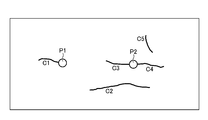
- FIG. 12 is a damage diagram including information on cracks.
- the damage diagram shown in FIG. 12 shows cracks C1 to C5 and P-con traces P1 and P2.
- crack C1 is a sinking crack generated in P-con trace P1
- cracks C4 and C5 are It is a sinking crack generated in the P-con trace P2.
- the damage diagram is represented by a drawing pattern by polylines along each crack C1 to C5, and can be used as CAD data.
- FIG. 13 is a chart showing an example of the damage quantity table included in the damage detection result, and corresponds to the damage chart shown in FIG.
- the damage quantity table shown in FIG. 13 has items of damage identification information (ID: identification), damage type, size (width), size (length), and size (area), and each item corresponds to each damage. Information to be done is described.
- each crack C1 to C5 are quantified, and this information is described in association with the damage ID in the damage quantity table.
- the first trained model 21A shown in FIG. 5 outputs each damaged area as a damage detection result 27A when the image 13 obtained by photographing the structure is input, but the damage detection result 27A is erroneously detected or failed. It may be detected accurately.
- the damaged area is classified in pixel units or in units of a group of several pixels, so it may lack accuracy. Further, it may be better to connect the cracks detected as two cracks as one crack. This is because it can be inferred that cracks are connected inside the concrete.
- the CPU 20 performs an edit instruction reception process for receiving an edit instruction for the damage detection result through an operation with the operation unit 18 (for example, a mouse) operated by the user, and edits the damage detection result according to the received edit instruction. Perform processing.
- the operation unit 18 for example, a mouse
- the damage detection result in the case of linear damage (cracking), in the case of a crack in which the end points of the polylines along the crack are close to each other, editing in which the end points are connected can be considered.
- the distance between the end points of the cracked polyline is measured after the damage detection process, and if the measured distance is less than the threshold value, the end points may be automatically connected or automatically according to the user's instruction. You may connect with.
- the threshold value may be a default value or may be user-configurable.
- a threshold value for the length and width of the crack may be set, and damage detection results smaller than the threshold value may be automatically deleted.
- the damage detection result may be deleted automatically after the damage detection process, or may be deleted according to the user's instruction.
- the threshold value may be a default value or may be user-configurable.
- FIG 14 and 15 are diagrams showing an editing example of the damage detection result, respectively.
- editing the damage detection result it is preferable to set the transparency of the color that fills the crack image to be high so that the image of the structure can be easily seen.
- FIG. 14 is a diagram showing a method of adding vertices to the polyline along the crack.
- the polyline is drawn by connecting a plurality of vertices along the crack (vertices indicated by squares in FIG. 14).
- FIG. 15 is a diagram showing a method of removing vertices from a polyline along a crack.
- the above editing functions include a function to select the entire poly line by clicking the line connecting the vertices and delete the entire poly line at once, and a function to manually add a new poly line to the crack detection omission point. Has.
- FIG. 16 is a flowchart showing an embodiment of the damage evaluation method according to the present invention.
- each step shown in FIG. 16 is performed by, for example, a processor configured by the CPU 20 of the damage evaluation device 10 shown in FIG.
- the processor acquires an image of the structure to be evaluated from the image acquisition unit 12, the image database 14, or the like (step S10).
- the first trained model 21A (FIG. 5) that functions as a damage detection processing unit detects damage (cracks) in the structure based on the image acquired in step S10 (step S12).
- the second trained model and 21B (FIG. 5), which function as the feature area detection process, detect the structure feature area (the area of the P-con trace) related to the construction of the structure based on the image acquired in step S10. (Step S14).
- the processor determines whether or not damage has been detected by the damage detection process performed in step S12 (step S16), and if damage has been detected (in the case of "Yes"), proceeds to step S18.
- step S18 from the damages (cracks) detected in step S12, specific damages (sinking cracks) related to the structural feature region are selected, and the process proceeds to step S20.
- step S20 it is determined whether or not the specific damage has been selected, and if it is determined that the specific damage has been selected (in the case of “Yes”), the processor outputs the information on the specific damage (step S22). ..
- the output of the specific damage information is performed, for example, by superimposing the damage image on the image, displaying the damage image alone on the display unit, or outputting the CAD data showing the damage diagram as a file. Further, it is preferable to specify the size (length) of the specific damage (sinking crack), color-code the sinking crack image according to the specified size, or output the line type differently.
- step S20 if it is determined in step S20 that the specific damage is not sorted (in the case of "No"), the damage (crack) detected in step S12 is output with crack information so that it can be identified as not a sinking crack. (Step S24). For example, a crack image is output with a color different from that of the sink crack or a line type. Note that step S24 may be omitted so that information other than specific damage (sinking and cracking) is not output.
- examples of P-con traces and joints are given as structural feature areas related to the construction of structures, but the present invention is not limited to this, and other structural feature areas such as joints may be detected. good.
- specific damage related to the structural feature area sinking cracks and crescent cracks were mentioned as examples, but water leaked from joints, joints, etc., or flowed out of the concrete member due to water leakage, etc., and water evaporated. Damage such as free lime on which the lime component appears on the surface is a specific damage related to the structural feature area (joint, joint area).
- the hardware that realizes the damage evaluation device according to the present invention can be configured by various processors.
- Various processors include CPUs (Central Processing Units) and FPGAs (Field Programmable Gate Arrays), which are general-purpose processors that execute programs and function as various processing units, and whose circuit configurations can be changed after manufacturing. It includes a dedicated electric circuit, which is a processor having a circuit configuration specially designed for executing a specific process such as a programmable logic device (PLD) and an ASIC (Application Specific Integrated Circuit).
- PLD programmable logic device
- ASIC Application Specific Integrated Circuit
- one processing unit may be composed of a plurality of FPGAs or a combination of a CPU and an FPGA.
- a plurality of processing units may be configured by one processor.
- one processor is configured by a combination of one or more CPUs and software, as represented by a computer such as a client or a server.
- a processor functions as a plurality of processing units.
- SoC System On Chip
- a processor that realizes the functions of the entire system including a plurality of processing units with one IC (Integrated Circuit) chip is used. be.
- the various processing units are configured by using one or more of the above-mentioned various processors as a hardware-like structure.
- the hardware structure of these various processors is, more specifically, an electric circuit (circuitry) in which circuit elements such as semiconductor elements are combined.
- the present invention also includes a damage evaluation program that causes the computer to function as a damage evaluation device according to the present invention by being installed in the computer, and a storage medium in which the damage evaluation program is recorded.
Landscapes
- Engineering & Computer Science (AREA)
- Physics & Mathematics (AREA)
- General Physics & Mathematics (AREA)
- Theoretical Computer Science (AREA)
- Quality & Reliability (AREA)
- Computer Vision & Pattern Recognition (AREA)
- Multimedia (AREA)
- Geometry (AREA)
- Investigating Materials By The Use Of Optical Means Adapted For Particular Applications (AREA)
- Image Analysis (AREA)
Abstract
構造物の施工と関連して発生する構造物の表層の損傷を自動評価することができる損傷評価装置、方法及びプログラムを提供する。プロセッサを備えた構造物の損傷評価装置において、プロセッサは、構造物を撮影した画像を取得する画像取得処理と、取得した画像に基づいて構造物の損傷(ひび割れ)を検出する損傷検出処理と、取得した画像に基づいて構造物の施工に関連した構造物特徴領域(Pコン跡の領域)を検出する特徴領域検出処理と、検出した損傷のうち、検出した構造物特徴領域と関連性のある特定損傷(沈みひび割れ)を選別する選別処理と、選別した特定損傷の情報を出力する情報出力処理と、を行う。このように特定損傷の情報を出力することで、構造物の施工と関連して発生する構造物の表層の損傷を自動評価することができ、施工方法の妥当性の検証や施工方法の改善に活用することができる。
Description
本発明は損傷評価装置、方法及びプログラムに係り、特に構造物の施工と関連して発生する構造物の損傷を評価する技術に関する。
従来、新設の構造物の表層部に生じる不具合を目視評価し、施工方法の妥当性検証や施工方法改善に活かしていくことが、提案されている(非特許文献1)。
しかしながら、目視評価のため人により結果がばらつくという問題があり、統一的な基準での自動評価の実現が望まれる。
また、構造物の維持管理及び補修を行うために構造物の点検評価が行われるが、構造物を撮影した画像に基づいて自動的に構造物の損傷を評価する技術が知られている(特許文献1、2)。
特許文献1には、構造物の表面を示す画像を画像解析して構造物の表面のひび割れを検出するとともに、検出したひび割れの特徴量(ひび割れの方向、長さ、幅、エッジの強度、及びエッジの密度等)を検出し、検出した特徴量に基づいて各ひび割れをグルーピングし、ひび割れを塗り潰したひび割れ画像を表示させる際に、グループごとに異なる線種又は色を用いてひび割れ画像を表示させる画像処理方法が記載されている。
また、特許文献2には、時系列的に取得されたトンネル覆工面画像を対比し、数mm程度変化したひび割れでも認識できるように、今回のトンネル覆工面画像を補正することができるトンネル覆工面画像の補正方法が記載されている。
特許文献2に記載のトンネル覆工面画像の補正方法は、トンネル覆工面における位置不変の設置物又は目地を検出し、異なる時系列画像同士で設置物又は目地の位置を一致させる画像処理を行い、位置が正規化されたトンネル覆工面画像を生成することで、変状の時系列管理に用いるトンネル覆工面画像を補正する。
コンクリート構造物の品質確保の手引き(案)、平成27年12月、(p.17-20, 国土交通省東北地方整備局)、インターネット<http://www.thr.mlit.go.jp/road/sesaku/tebiki/kyoukyaku.pdf>
ところで、構造物の損傷、劣化には、構造物の施工に起因して発生するものがある。
特許文献1には、構造物の表面のひび割れを、検出したひび割れの特徴量に基づいてグルーピングする記載があるが、構造物の施工に関連して発生する損傷を選別する記載はない。
また、特許文献2には、コンクリート構造物のひび割れとともに、目地を検出する記載があるが、位置不変の目地は、前回のトンネル覆工面画像と今回のトンネル覆工面画像とを一致させる画像処理(アフィン変換)を行うために使用するものであり、損傷を選別するために使用されるものではない。
本発明はこのような事情に鑑みてなされたもので、構造物の施工と関連して発生する構造物の表層の損傷を自動評価することができる損傷評価装置、方法及びプログラムを提供することを目的とする。
上記目的を達成するために第1態様に係る発明は、プロセッサを備えた構造物の損傷評価装置であって、プロセッサは、構造物を撮影した画像を取得する画像取得処理と、取得した画像に基づいて構造物の損傷を検出する損傷検出処理と、取得した画像に基づいて構造物の施工に関連した構造物特徴領域を検出する特徴領域検出処理と、検出した損傷のうち、検出した構造物特徴領域と関連性のある特定損傷を選別する選別処理と、選別した特定損傷の情報を出力する情報出力処理と、を行う。
本発明の第1態様によれば、構造物を撮影した画像に基づいて検出した損傷のうち、構造物の施工に関連した構造物特徴領域と関連性のある特定損傷を自動的に選別し、選別した特定損傷の情報を出力するようにしたため、構造物の施工と関連して発生する構造物の表層の損傷を自動評価することができ、施工方法の妥当性の検証や施工方法の改善に活用することができる。
本発明の第2態様に係る損傷評価装置において、損傷検出処理は、画像を入力すると、構造物の損傷ごとに各損傷の領域を認識結果として出力する第1学習済みモデルが実行することが好ましい。
本発明の第3態様に係る損傷評価装置において、構造物の損傷は、構造物のひび割れであり、特定損傷は、構造物のひび割れのうちの構造物の施工に起因して発生した特定ひび割れである。特定ひび割れは、例えば、コンクリート構造物の表層に発生する沈みひび割れ、三日月ひび割れ等である。
本発明の第4態様に係る損傷評価装置において、特徴領域検出処理は、画像を入力すると、構造物特徴領域を認識結果として出力する第2学習済みモデルが実行することが好ましい。
本発明の第5態様に係る損傷評価装置において、構造物特徴領域は、構造物の施工に起因して発生する特定損傷である特定ひび割れに関連する施工跡を示す領域である。特定ひび割れに関連する施工跡は、例えば、コンクリート構造物の表層のPコン跡、目地、打ち継ぎ目などである。
本発明の第6態様に係る損傷評価装置において、選別処理は、構造物特徴領域と接触する損傷、又は構造物特徴領域と重なる損傷を特定損傷として選別することが好ましい。
本発明の第7態様に係る損傷評価装置において、選別処理は、構造物特徴領域のサイズを膨張させる膨張処理を含み、膨張処理された構造物特徴領域と接触する損傷、又は膨張処理された構造物特徴領域と重なる損傷を特定損傷として選別することが好ましい。構造物特徴領域のサイズを膨張させる割合又は膨張量は、予め設定された値でもよいし、ユーザが適宜設定した値でもよい。
本発明の第8態様に係る損傷評価装置において、プロセッサは、特定損傷のサイズを特定するサイズ特定処理を行うことが好ましい。
本発明の第9態様に係る損傷評価装置において、構造物の損傷は、構造物のひび割れを含み、特定損傷は、構造物のひび割れのうちの構造物の施工に起因して発生した特定ひび割れであり、サイズ特定処理は、特定ひび割れの画像上の長さと、構造物特徴領域の画像上の長さとの相対長さを算出し、算出した相対長さを特定損傷のサイズとすることができる。
本発明の第10態様に係る損傷評価装置において、構造物の損傷は、構造物のひび割れを含み、特定損傷は、構造物のひび割れのうちの構造物の施工に起因して発生した特定ひび割れであり、サイズ特定処理は、特定ひび割れの画像上の長さと、構造物特徴領域の画像上の長さと、構造物特徴領域の実寸サイズとに基づいて特定損傷の実寸サイズを算出することが好ましい。
本発明の第11態様に係る損傷評価装置において、構造物の損傷は、構造物のひび割れを含み、特定損傷は、構造物のひび割れのうちの構造物の施工に起因して発生した特定ひび割れであり、画像には、実寸法が既知のスケール基準を有する構造物が撮影され、サイズ特定処理は、特定ひび割れの画像上の長さと、スケール基準の画像上の長さとに基づいて特定損傷の実寸サイズを算出することが好ましい。
本発明の第12態様に係る損傷評価装置において、構造物の損傷は、構造物のひび割れを含み、特定損傷は、構造物のひび割れのうちの構造物の施工に起因して発生した特定ひび割れであり、サイズ特定処理は、特定ひび割れの画像上の長さと、画像を撮影したカメラの撮影条件及びカメラ情報とに基づいて特定損傷の実寸サイズを算出することが好ましい。カメラの撮影条件には、例えば、カメラと特定ひび割れとの距離が含まれ、カメラ情報には、例えば、焦点距離、イメージセンサのサイズ、画素数、又は画素ピッチが含まれる。
本発明の第13態様に係る損傷評価装置において、情報出力処理は、特定損傷の属性に応じて各特定損傷を識別可能に出力することが好ましい。特定損傷の属性には、損傷の長さ、幅、面積などが含まれる。また、特定損傷の属性に応じて各特定損傷を色分け、線種の違いなどにより識別可能にすることが好ましい。
本発明の第14態様に係る損傷評価装置において、情報出力処理は、特定損傷の属性に応じて、特定損傷に対応する構造物特徴領域を識別可能に出力することが好ましい。
本発明の第15態様に係る損傷評価装置において、プロセッサは、構造物特徴領域の総数と特定損傷に対応する構造物特徴領域の個数との割合を算出し、情報出力処理は、算出した割合を出力することが好ましい。
本発明の第16態様に係る損傷評価装置において、プロセッサは、ユーザにより操作される操作部から、検出した損傷の検出結果及び検出した構造物特徴領域の検出結果のうちの少なくとも一方の編集指示を受け付ける編集指示受付処理と、受け付けた編集指示にしたがって検出結果を編集する編集処理と、を行うことが好ましい。
本発明の第17態様に係る損傷評価装置において、情報出力処理は、特定損傷の情報をディスプレイに出力して表示させ、又はファイルにしてメモリに保存させることが好ましい。
本発明の第18態様に係る損傷評価装置において、特定損傷の情報は、損傷識別情報、損傷種類及びサイズの項目を有し、特定損傷ごとに各項目に対応する情報が記載された損傷数量表を含むことが好ましい。
第19態様に係る発明は、プロセッサにより構造物の損傷評価を行う損傷評価方法であって、プロセッサの各処理は、構造物を撮影した画像を取得するステップと、取得した画像に基づいて構造物の損傷を検出するステップと、取得した画像に基づいて構造物の施工に関連した構造物特徴領域を検出するステップと、検出した損傷のうち、検出した構造物特徴領域と関連性のある特定損傷を選別するステップと、選別した特定損傷の情報を出力するステップと、を含む。
第20態様に係る発明は、構造物の損傷評価を行う方法をコンピュータに実行させる損傷評価プログラムであって、方法は、構造物を撮影した画像を取得するステップと、取得した画像に基づいて構造物の損傷を検出するステップと、取得した画像に基づいて構造物の施工に関連した構造物特徴領域を検出するステップと、検出した損傷のうち、検出した構造物特徴領域と関連性のある特定損傷を選別するステップと、選別した特定損傷の情報を出力するステップと、を含む。
本発明によれば、構造物の施工と関連して発生する構造物の表層の損傷を自動評価することができる。
以下、添付図面に従って本発明に係る損傷評価装置、方法及びプログラムの好ましい実施形態について説明する。
[本発明の概要]
図1は、構造物の損傷の一例を示す図であり、図1(A)は、構造物の施工跡を有するコンクリート構造物を撮影した元画像を示し、図1(B)は、ひび割れ検出結果(ひび割れ画像)を元画像上に重畳表示した合成画像をしている。
図1は、構造物の損傷の一例を示す図であり、図1(A)は、構造物の施工跡を有するコンクリート構造物を撮影した元画像を示し、図1(B)は、ひび割れ検出結果(ひび割れ画像)を元画像上に重畳表示した合成画像をしている。
本例の構造物の施工跡は、プラスチックコーン(以下、「Pコン」という)の跡であり、図1上のPは、Pコン跡を示す。以下、Pコン跡Pについて説明する。
壁、柱、梁などのコンクリート構造物の施工は、鉄筋及び型枠を組立ててコンクリートを打設するのが一般的である。型枠は、両端にねじ部を有する棒状のセパレータと、そのセパレータの両端部に取り付けられるPコンとより所望の間隔で固定され、型枠内にコンクリートが流し込まれるが、コンクリートが固まると、型枠及びPコンが外される。
Pコンが外されると、セパレータのねじ部が露出した穴が現れる。この穴をモルタルで塞いだ円形の跡がPコン跡Pである。
図1(B)のC1~C3は、Pコン跡Pの周辺のひび割れを示している。ひび割れC1~C3は、図1(A)の元画像から検出されたひび割れの領域を、特定の色で塗り潰したひび割れ画像で表現されている。
Pコン跡Pの周辺のひび割れC1~C3は、沈みひび割れとして分類され、構造物の施工に起因して発生するひび割れの一つである。沈みひび割れは、コンクリートの打込み後の沈みやブリーディングによる変位を、型枠用セパレータ、表面の型枠などが拘束することによって生じるひび割れである。
本発明の一態様は、構造物を撮影した画像から構造物の損傷を検出し、検出した損傷のうち、構造物の施工に関連性のある損傷(特定損傷)を選別し、選別した特定損傷の情報を出力する。これにより、構造物の施工方法の妥当性の検証や施工方法の改善に活用可能にする。
図1に示す例では、構造物の施工に関連した構造物特徴領域がPコン跡Pの領域であり、Pコン跡の領域と関連性のある特定損傷が、沈みひび割れC1~C3である。
図2は、損傷検出から特定損傷の選別の流れの一例を示す図である。
図2(A)に示すように、構造物を撮影した画像に基づいて構造物の損傷(本例では、ひび割れ)を検出する。ひび割れの検出は、人工知能(AI:artificial intelligence)により行ってもよいし、画像処理アルゴリズムにより行ってもよい。
また、図2(B)に示すように、構造物を撮影した画像に基づいて構造物の施工に関連した構造物特徴領域(本例では、Pコン跡Pの領域)を検出する。Pコン跡Pの領域の検出は、AIにより行ってもよいし、画像処理アルゴリズムにより行ってもよい。また、ユーザの手動による指示入力を受け付けることで検出するようにしてもよい。
続いて、図2(C)に示すように、検出したひび割れのうち、Pコン跡Pの領域と関連性のある沈みひび割れ(特定ひび割れ)C1~C4を選別し、選別した沈みひび割れC1~C4を、他のひび割れと識別可能に色分け、又は線種を変えて出力する。
図3は、検出したひび割れが、沈みひび割れか否かを選別する方法を説明するために用いた図である。
図3(A)は、それぞれ検出されたひび割れC1~C3とPコン跡Pとを示している。
ひび割れC1~C3が、Pコン跡Pの領域と関連性のある沈みひび割れか否かの選別は、ひび割れC1~C3が、Pコン跡Pの領域と接触する場合、又はPコン跡Pの領域と重なる場合に沈みひび割れとして選別する。
この選別方法の場合、ひび割れC1~C3は、いずれもPコン跡Pの領域から離間しているため、沈みひび割れなしと認識される(図3(B))。
一方、図3(C)に示すように、Pコン跡Pの領域のサイズを、Pコン跡P1の領域のサイズに膨張させる。
Pコン跡Pの領域の膨張処理は、円形のPコン跡Pの中心から径方向に一定の割合でPコン跡Pの領域を膨張させ、又は円形のPコン跡Pの外形を一定の膨張量(幅)だけ拡大させることで、Pコン跡Pの領域を膨張させることができる。尚、Pコン跡Pの領域のサイズを膨張させる割合又は膨張量は、予め設定された値でもよいし、ユーザが適宜設定した値でもよい。
そして、ひび割れC1~C3が、膨張処理されたPコン跡P1の領域と接触する場合、又はPコン跡P1の領域と重なる場合に沈みひび割れとして選別する(図3(D))。
この選別方法の場合、ひび割れC1~C3は、いずれもPコン跡P1の領域と接触し、又はPコン跡P1の領域と重なるため、沈みひび割れとして選別される。
尚、Pコン跡の領域は、検出したPコンの領域を膨張処理により拡大する場合に限らず、本来のPコン跡の領域よりもやや広い領域をPコン跡の領域として検出されるようにしてもよい。
また、ひび割れC1~C3とPコン跡P1の領域とが最も接近する距離を算出し、その距離が閾値以内の場合に、沈みひび割れとして選別するようにしてもよい。
[損傷評価装置のハードウエア構成]
図4は、本発明に係る損傷評価装置のハードウエア構成の一例を示すブロック図である。
図4は、本発明に係る損傷評価装置のハードウエア構成の一例を示すブロック図である。
図1に示す損傷評価装置10としては、パーソナルコンピュータ又はワークステーションを使用することができる。本例の損傷評価装置10は、主として画像取得部12と、画像データベース14と、記憶部16と、操作部18と、CPU(Central Processing Unit)20と、RAM(Random Access Memory)22と、ROM(Read Only Memory)24と、表示制御部26とから構成されている。
画像取得部12は、入出力インターフェースに相当し、本例では評価対象の構造物を撮影した画像等を取得する。評価対象の構造物は、例えば、橋梁、トンネル、建物等の壁、柱、梁などを含む。
画像取得部12が取得する画像は、例えば、カメラを搭載したドローン(無人飛行体)やロボット、又は人手により構造物を撮影した多数の画像(画像群)である。画像群は、構造物の全体を網羅するものであり、かつ隣接する各画像は、重複していることが好ましい。
画像取得部12により取得した画像群は、画像データベース14に格納される。
記憶部16は、ハードディスク装置、フラッシュメモリ等から構成されるメモリであり、記憶部16には、オペレーティングシステム、損傷評価プログラムの他、構造物を示すCAD(computer-aided design)データ、及びファイル化された損傷の情報が記憶される。損傷の情報は、損傷画像、損傷図(CADデータ)等の損傷評価結果を含む。
評価対象の構造物のCADデータは、予めCADデータが存在する場合には、それを使用することができる。構造物のCADデータが存在しない場合には、画像データベース14に保存された画像群を元に自動的に作成することができる。
画像データベース14に格納された画像群が、ドローンに搭載されたカメラで撮影されている場合、画像群の互いに重複する画像間の特徴点を抽出し、抽出した特徴点に基づいて、ドローンに搭載されたカメラの位置及び姿勢を推定し、また、カメラの位置及び姿勢の推定結果から同時に特徴点の3次元位置を推定した3次元点群モデルを生成することができる。
ドローンによりカメラの撮影位置が動いていく画像群の中から、多数の特徴点の動きをトラッキングし、構造物の3次元構造(Structure)とカメラ姿勢(Motion)とを同時に推定するStructure from Motion(SfM)手法がある。近年、bundle adjustmentという最適化計算法が開発され、高精度な出力を出せるようになっている。
尚、SfM手法を適用する場合に必要なカメラのパラメータ(焦点距離、イメージセンサの画像サイズ、画素ピッチ等)は、記憶部16に記憶させたものを使用することができる。また、生成した3次元点群モデルに基づいて構造物のCADデータを生成することができる。
操作部18は、コンピュータに有線接続又は無線接続されるキーボード及びマウス等を含み、コンピュータの通常の操作指示を行う操作部として機能する他に、構造物を撮影した画像に基づいて検出された構造物の損傷の検出結果、Pコン跡等の構造物特徴領域の検出結果をユーザ操作により編集する操作部として機能する。尚、損傷の検出結果の編集等の詳細については後述する。
CPU20は、記憶部16又はROM24等に記憶された各種のプログラムを読み出し、各部を統括制御するとともに、構造物を撮影した画像に基づいて構造物の損傷を検出する損傷検出処理、構造物の施工に関連した構造物特徴領域(Pコン跡の領域等)を検出する特徴領域検出処理、検出した損傷のうちの構造物特徴領域と関連性のある特定損傷を選別する選別処理、及び選別した特定損傷の情報を出力する情報出力処理等を行う。
構造物を撮影した画像に基づいて損傷を検出する損傷検出処理、及び構造物特徴領域を検出する特徴領域検出処理は、それぞれAIにより行うことができる。
AIとしては、例えば、畳み込みニューラルネットワーク(CNN:Convolution Neural Network)による学習済みモデルを使用することができる。
図5は、CPU等により構成された損傷検出処理部及び特徴領域検出処理部の実施形態を示す概念図である。
図5において、損傷検出処理部及び特徴領域検出処理部は、それぞれ第1学習済みモデル21A及び第2学習済みモデル21Bから構成されている。
第1学習済みモデル21A及び第2学習済みモデル21Bは、それぞれ入力層と中間層と出力層とを備え、各層は複数の「ノード」が「エッジ」で結ばれる構造となっている。
CNNの入力層には、構造物を撮影した画像13が入力される。中間層は、畳み込み層とプーリング層とを1セットとする複数セットを有し、入力層から入力した画像から特徴を抽出する部分である。畳み込み層は、前の層で近くにあるノードにフィルタ処理し(フィルタを使用した畳み込み演算を行い)、「特徴マップ」を取得する。プーリング層は、畳み込み層から出力された特徴マップを縮小して新たな特徴マップとする。「畳み込み層」は、画像からのエッジ抽出等の特徴抽出の役割を担い、「プーリング層」は抽出された特徴が、平行移動などによる影響を受けないようにロバスト性を与える役割を担う。
CNNの出力層は、中間層により抽出された特徴を示す特徴マップを出力する部分である。本例の第1学習済みモデル21Aの出力層は、例えば、画像に写っている構造物の損傷ごとの領域をピクセル単位、もしくはいくつかのピクセルを一塊にした単位で領域分類(セグメンテーション)した推論結果(認識結果)を、損傷検出結果27Aとして出力し、同様に本例の第2学習済みモデル21Bの出力層は、例えば、画像に写っている構造物の施工に関連した構造物特徴領域をピクセル単位、もしくはいくつかのピクセルを一塊にした単位で領域分類した推論結果を、構造物特徴領域検出結果27Bとして出力する。
例えば、第1学習済みモデル21Aは、ひび割れを検出するように機械学習された学習済みモデルであり、第2学習済みモデル21Bは、Pコン跡を検出するように機械学習された学習済みモデルである。
尚、第1学習済みモデル21A及び第2学習済みモデル21Bは、1つの学習済みモデルで構成し、それぞれ損傷検出結果27A及び構造物特徴領域検出結果27Bを出力するように構成してもよい。
図4に戻って、CPU20は、第1学習済みモデル21A及び第2学習済みモデル21Bによりそれぞれ検出された損傷検出結果27A及び構造物特徴領域検出結果27Bに基づいて、検出された損傷のうち、検出された構造物特徴領域と関連性のある特定損傷を選別する選別処理を行う。本例では、検出されたひび割れのうち、Pコン跡と関連性のある沈みひび割れ(特定ひび割れ)を選別する。沈みひび割れの選別は、図3を使用して説明した方法により行うことができ、ここでは詳細な説明は省略する。
CPU20は、選別した特定損傷の情報を、表示制御部26を介して表示部(ディスプレイ)30に出力して表示させ、又はファイルにして記憶部(メモリ)16に保存させる。また、CPU20は、構造物特徴領域の情報も表示制御部26を介して表示部30に出力して表示させ、又はファイルにして記憶部16に保存させることが好ましい。
RAM22は、CPU20の作業領域として使用され、読み出されたプログラムや各種のデータを一時的に記憶する記憶部として用いられる。
表示制御部26は、表示部30に表示させる表示用データを作成し、表示部30に出力する部分であり、本例ではCPU20により検出され、選別された特定損傷の情報等を表示部30に表示させ、操作部18からのユーザ操作に基づく特定損傷の情報等の編集用の画面等を表示部30に表示させる。
表示部30は、コンピュータに接続可能な液晶モニタ等の各種のディスプレイが用いられ、表示制御部26から入力する構造物を撮影した画像とともに、画像から検出された特定損傷の情報等を表示し、また、操作部18とともにユーザインターフェースの一部として使用される。
上記構成の損傷評価装置10のCPU20を含むプロセッサは、記憶部16又はROM24に記憶されている損傷評価プログラムを読み出し、損傷評価プログラムを実行することで、上記の各処理を行う。
<損傷評価装置の作用>
次に、図4に示した損傷評価装置10の作用について、構造物として橋梁を例に説明する。
次に、図4に示した損傷評価装置10の作用について、構造物として橋梁を例に説明する。
図6は、評価対象の構造物を撮影した画像と特定損傷の情報等の第1表示例を示す図である。
損傷評価装置10のCPU20、記憶部16に記憶された損傷評価プログラム、RAM22及びROM24、表示制御部26等はプロセッサを構成し、プロセッサは、以下に示す各種の処理を行う。
プロセッサは、画像取得部12から評価対象の構造物(コンクリート構造物の表層)を撮影した画像を取得する画像取得処理を行う。画像データベース14に構造物の画像が格納されている場合には、プロセッサは、画像データベース14から評価対象の構造物の画像を読み出す。この場合、プロセッサは、複数枚の画像を取得し、取得した複数枚の画像の各重複領域の画像が一致するように複数枚の画像をパノラマ合成する画像処理を行う。
パノラマ合成されるパノラマ合成画像は、図6(A)に示すようにコンクリート構造物の表面に正射影されたオルソ画像であることが好ましい。
画像から0.1mm以下のひび割れを検出するには、高解像度の画像が要求されるため、1枚の画像の撮影範囲は小さくなる。ある程度の大きさの構造物の画像を取得するには、複数枚の画像をパノラマ合成することが好ましいが、高解像度のカメラやひび割れ検出が要求されるひび割れ幅が大きい場合には、1枚の画像でもよい。
図5に示した損傷検出処理部及び特徴領域検出処理部として機能する第1学習済みモデル21A及び第2学習済みモデル21Bは、パノラマ合成画像(画像13)を入力すると、第1学習済みモデル21Aは、入力した画像13に基づいてひび割れを検出し、検出したひび割れを示す損傷検出結果27Aを出力し、第2学習済みモデル21Bは、入力した画像13に基づいてPコン跡を検出し、検出したPコン跡を示す構造物特徴領域検出結果27Bを出力する。
続いて、プロセッサは、損傷検出結果27Aと構造物特徴領域検出結果27Bとに基づいて、損傷検出結果27A(ひび割れ)のうち、構造物特徴領域検出結果27B(Pコン跡)と関連性のある沈みひび割れを選別する選別処理を行う。この選別処理は、図3を使用して説明したように、ひび割れの領域とPコン跡の領域との接触、又はひび割れの領域とPコン跡の領域と重なりを検出し、Pコン跡の領域と接触又は重なるひび割れを、沈みひび割れとして選別する。
次に、プロセッサは、特定損傷(沈みひび割れ)のサイズを、対応するPコン跡ごとに特定するサイズ特定処理を行う。
以下、沈みひび割れのサイズを特定するサイズ特定処理について説明する。
<第1サイズ特定処理>
第1サイズ特定処理は、沈みひび割れの画像上の長さと、その沈みひび割れに対応するPコン跡の画像上の長さ(本例では、Pコン跡の直径)との相対長さを算出し、算出した相対長さを沈みひび割れのサイズとする。
第1サイズ特定処理は、沈みひび割れの画像上の長さと、その沈みひび割れに対応するPコン跡の画像上の長さ(本例では、Pコン跡の直径)との相対長さを算出し、算出した相対長さを沈みひび割れのサイズとする。
第1サイズ特定処理によれば、沈みひび割れのサイズは、Pコン跡の直径のX倍として特定される。尚、X倍は、例えば、ゼロ(沈みひび割れなし)、3倍未満、3倍以上5倍未満、5倍以上のように4段階の階級で表すようにしてもよい。
<第2サイズ特定処理>
第2サイズ特定処理は、沈みひび割れの画像上の長さと、その沈みひび割れに対応するPコン跡の画像上の直径と、Pコン跡の実寸サイズとに基づいて沈みひび割れの実寸サイズを算出する。
第2サイズ特定処理は、沈みひび割れの画像上の長さと、その沈みひび割れに対応するPコン跡の画像上の直径と、Pコン跡の実寸サイズとに基づいて沈みひび割れの実寸サイズを算出する。
即ち、沈みひび割れの実寸サイズは、上記の(相対長さ(X倍))×(Pコン跡の実寸サイズ)により算出することができる。
Pコン跡の実寸サイズは、ユーザが操作部18により入力した数値、あるいは既定の数値を適用することができる。
<第3サイズ特定処理>
第3サイズ特定処理は、実寸法が既知のスケール基準を有する構造物が撮影された画像の場合に適用される。スケール基準は、構造物の表面に張り付けた目盛り付きのスケールでもよいし、構造物の表面に設けられた実寸法が既知の鋼材、ボルトの頭等でもよい。
第3サイズ特定処理は、実寸法が既知のスケール基準を有する構造物が撮影された画像の場合に適用される。スケール基準は、構造物の表面に張り付けた目盛り付きのスケールでもよいし、構造物の表面に設けられた実寸法が既知の鋼材、ボルトの頭等でもよい。
第3サイズ特定処理は、沈みひび割れの画像上の長さと、実寸法が既知のスケール基準の画像上の長さとに基づいて沈みひび割れの実寸サイズを算出する。
<第4サイズ特定処理>
第4サイズ特定処理は、沈みひび割れの画像上の長さと、画像を撮影したカメラの撮影条件及びカメラ情報とに基づいて沈みひび割れの実寸サイズを算出する。
第4サイズ特定処理は、沈みひび割れの画像上の長さと、画像を撮影したカメラの撮影条件及びカメラ情報とに基づいて沈みひび割れの実寸サイズを算出する。
カメラの撮影条件には、例えば、カメラと沈みひび割れとの距離(撮影距離)、カメラの撮影方向と構造物の表面との角度等が含まれ、カメラ情報には、例えば、撮影レンズの焦点距離、イメージセンサのサイズ、画素数、又は画素ピッチ等が含まれる。
いま、カメラの撮影方向と構造物の表面とが直交している場合、撮影距離をD、撮影レンズの焦点距離をf、沈みひび割れの画像上の長さをイメージセンサ上の長さに換算した長さをu、画素ピッチをpとすると、沈みひび割れの実寸サイズLは、次式、
[数1]
L=D×u×p/f
により算出することができる。
[数1]
L=D×u×p/f
により算出することができる。
尚、上記第1サイズ特定処理から第4サイズ特定処理において、1つのPコン跡の領域に関連して複数本の沈みひび割れが選別された場合、複数本の沈みひび割れのうちの最も長い沈みひび割れの長さを、そのPコン跡に対応する沈みひび割れの長さ(代表長さ)とする。
また、沈みひび割れの情報には、沈みひび割れの長さの他に、沈みひび割れの幅、及び面積を含めることができる。
図6(B)は、表示部の画面に表示される特定損傷の情報等の第1表示例を示す図である。
図6(B)に示すように表示部の画面には、沈みひび割れに対応するPコン跡の領域を、対応する沈みひび割れの属性(サイズ等)に応じて色分けし、パノラマ合成画像(図6(B))に重畳した画像が表示され、また、各種のPコン跡に関する情報等が表示されている。
図6(B)に示す例では、24個のPコン跡の領域が、第1サイズ特定処理の結果に基づいて4色(赤色、黄色、緑色、青色)に色分けされている。
図6(B)上で、Pコン跡を示すPR、PY、PG、PBは、以下の沈みひび割れを有するものである。
PR(赤色):Pコン跡直径の5倍以上の長さの沈みひび割れが発生しているPコン跡
PY(黄色):Pコン跡直径の3倍以上5倍未満の長さの沈みひび割れが発生しているPコン跡
PG(緑色):Pコン跡直径の3倍未満の長さの沈みひび割れが発生しているPコン跡
PB(青色):沈みひび割れが発生していないPコン跡
図6(B)に示すように、Pコン跡の総数は24個であり、上記のように色分けされたPコン跡PR、PY、PG、PBの個数は、それぞれ2個、6個、7個、9個である。プロセッサは、Pコン跡の総数と沈みひび割れに対応するPコン跡PR、PY、PGの個数との割合(発生割合)を算出し、その発生割合(本例では、63%)も表示させている。
PY(黄色):Pコン跡直径の3倍以上5倍未満の長さの沈みひび割れが発生しているPコン跡
PG(緑色):Pコン跡直径の3倍未満の長さの沈みひび割れが発生しているPコン跡
PB(青色):沈みひび割れが発生していないPコン跡
図6(B)に示すように、Pコン跡の総数は24個であり、上記のように色分けされたPコン跡PR、PY、PG、PBの個数は、それぞれ2個、6個、7個、9個である。プロセッサは、Pコン跡の総数と沈みひび割れに対応するPコン跡PR、PY、PGの個数との割合(発生割合)を算出し、その発生割合(本例では、63%)も表示させている。
図6(B)の表示画面によれば、Pコン跡の色により、各Pコン跡における沈みひび割れの有無、及び沈みひび割れが発生しているPコン跡の色から、その沈みひび割れのサイズを容易に確認することができ、また、沈みひび割れの発生割合等の情報も報知される。
尚、図6(B)では、Pコン跡を色分け表示するようにしたが、これに限らず、検出したひび割れの全部に色を付してひび割れ画像を表示し、又は選別した沈みひび割れのみに色を付してひび割れ画像を表示し、又はこれらを適宜切り替えて表示するようにしてもよい。
図7は、評価対象の構造物を撮影した画像と特定損傷の情報等の第2表示例を示す図である。
図7(A)は、評価対象の構造物を撮影した6枚の画像を示している。これらの6枚の画像は、それぞれ1つのPコン跡がほぼ画像中心になるように撮影された画像である。
図7(B)は、表示部の画面に表示される特定損傷の情報等の第2表示例を示す図である。
図7(B)に示すように表示部の画面には、6枚の画像が並べて一覧表示され、かつ各画像のPコン跡には、沈みひび割れの属性(サイズ等)に応じた色が付加されている。Pコン跡の色分けは、図6(B)と同様に行うことができる。
また、ひび割れ検出結果も表示させてもよい。例えば、ひび割れの長さに応じてひび割れ画像を色分けし、ひび割れの幅に応じてひび割れ画像を色分けし、検出したひび割れの全部に色を付してひび割れ画像を表示し、又は選別した沈みひび割れのみに色を付してひび割れ画像を表示し、又はこれらを適宜切り替えて表示するようにしてもよい。
図8は、図7(B)に示した画像に対して色分けしたひび割れ画像を追加した表示画面例を示す図である。
図8において、Pコン跡PRには、3本の沈みひび割れCR、CG、CYが発生しており、Pコン跡PYには、2本の沈みひび割れCG、CYが発生しており、Pコン跡PGには、2本の沈みひび割れCGが発生している。
尚、沈みひび割れCR、CG、CYは、各沈みひび割れの属性(長さ)に応じて、例えば、以下のように色分けされている。
CR(赤色):Pコン跡直径の5倍以上の長さの沈みひび割れ
CY(黄色):Pコン跡直径の3倍以上5倍未満の長さの沈みひび割れ
CG(緑色):Pコン跡直径の3倍未満の長さの沈みひび割れ
<構造物の施工に関連した構造物特徴領域と関連性のある特定損傷の他の例>
図9は、構造物の施工に関連した構造物特徴領域と関連性のある特定損傷の他の例を示す図である。
CY(黄色):Pコン跡直径の3倍以上5倍未満の長さの沈みひび割れ
CG(緑色):Pコン跡直径の3倍未満の長さの沈みひび割れ
<構造物の施工に関連した構造物特徴領域と関連性のある特定損傷の他の例>
図9は、構造物の施工に関連した構造物特徴領域と関連性のある特定損傷の他の例を示す図である。
図9(A)は、目地及びひび割れを含む評価対象の構造物が撮影された元画像である。
コンクリートの目地は、温度による収縮、膨張等でひび割れが発生しやすいコンクリートに対して、一定の間隔でコンクリートの表層に切り込みを入れることで、他の箇所でのひび割れを防止する役割があるが、目地ではひび割れが誘発される。尚、目地には、目地材(緩衝材)が充填される。
図9(A)に示す元画像から損傷としてひび割れを検出し、構造物の施工に関連した構造物特徴領域として目地の領域を検出する。
検出したひび割れのうち、ひび割れの両端が、目地の領域に接し、又は重なるひび割れを、特定ひび割れ(いわゆる「三日月ひび割れ」)として選別する。
尚、目地の領域は、検出した目地の領域を膨張処理により拡大し、あるいは本来の目地の領域よりもやや広い領域を目地の領域として検出されるようにしてもよい。
また、三日月ひび割れを選別する場合に、ひび割れの両端と目地の領域との最短距離をそれぞれ算出し、算出した各距離が閾値以内の場合に、三日月ひび割れとして選別するようにしてもよい。
図9(B)において、Jは、目地を示し、CYは、目地Jに両端が接する三日月ひび割れを示す。図9(B)は、目地Jの領域及び三日月ひび割れCYの領域をそれぞれ特定の色で塗り潰した目地画像及びひび割れ画像を、図9(A)の元画像に重畳表示した画面を示す。
図10は、構造物の施工に関連した構造物特徴領域と関連性のある特定損傷の更に他の例を示す図である。
図10(A)は、目地及びひび割れを含む評価対象の構造物が撮影された他の元画像である。図10(B)は、目地Jの領域及び三日月ひび割れCYの領域をそれぞれ特定の色で塗り潰した目地画像及びひび割れ画像を、図10(A)の元画像に重畳表示した画面を示す。
ユーザは、図9(B)及び図10(B)に示す表示画面により、目地Jに起因する三日月ひび割れCYを容易に認識することができ、目地の施工方法の妥当性の検証や目地の施工方法の改善に活用することができる。
図11は、損傷検出から特定損傷の選別の流れの他の例を示す図である。
図11(A)に示すように、構造物を撮影した画像に基づいて構造物の損傷(本例では、ひび割れ)を検出する。ひび割れの検出は、AIにより行ってもよいし、画像処理アルゴリズムにより行ってもよい。
また、図11(B)に示すように、構造物を撮影した画像に基づいて構造物の施工に関連した構造物特徴領域(図11の例では、目地Jの領域)を検出する。目地J領域の検出は、AIにより行ってもよいし、画像処理アルゴリズムにより行ってもよい。また、ユーザの手動による指示入力を受け付けることで検出するようにしてもよい。
続いて、図11(C)に示すように、検出したひび割れのうち、目地Jの領域と関連性のある三日月ひび割れ(特定ひび割れ)CYを選別し、選別した三日月ひび割れCYを、他のひび割れと識別可能に色分け、又は線種を変えて出力する。
尚、三日月ひび割れCYは、その両端が目地Jの領域に接しており、三日月状に湾曲しており、図11(C)の上方に示したひび割れのように、そのひび割れの一端のみが目地Jの領域に接しているものは、三日月ひび割れではない。
図12は、ひび割れの情報を含む損傷図である。
図12に示す損傷図には、ひび割れC1~C5と、Pコン跡P1、P2が示されており、特にひび割れC1は、Pコン跡P1に発生した沈みひび割れであり、ひび割れC4、C5は、Pコン跡P2に発生した沈みひび割れである。
また、損傷図は、各ひび割れC1~C5に沿ったポリラインによる描画パターンで表現され、CADデータとすることができる。
図13は、損傷検出結果に含まれる損傷数量表の一例を示す図表であり、図12に示した損傷図に対応している。
図13に示す損傷数量表には、損傷識別情報(ID:identification)、損傷種類、サイズ(幅)、サイズ(長さ)、サイズ(面積)の項目を有し、損傷ごとに各項目に対応する情報が記載されている。
ひび割れの場合、各ひび割れC1~C5の長さや幅の定量化が行われ、損傷数量表には、これらの情報が、損傷IDに関連付けられて記載される。
[損傷検出結果の編集]
図5に示した第1学習済みモデル21Aは、構造物を撮影した画像13を入力すると、各損傷領域を損傷検出結果27Aとして出力するが、損傷検出結果27Aは、誤って検出され、又は不正確に検出される場合がある。
図5に示した第1学習済みモデル21Aは、構造物を撮影した画像13を入力すると、各損傷領域を損傷検出結果27Aとして出力するが、損傷検出結果27Aは、誤って検出され、又は不正確に検出される場合がある。
例えば、損傷領域は、ピクセル単位、もしくはいくつかのピクセルを一塊にした単位で領域分類されるため、正確性に欠ける場合がある。また、2本のひび割れとして検出されたひび割れは、1本のひび割れとして連結した方がよい場合がある。コンクリート内部でひび割れが繋がっていると類推できる場合があるからである。
そこで、CPU20は、ユーザにより操作される操作部18(例えば、マウス)での操作を通じて損傷検出結果の編集指示を受け付ける編集指示受付処理を行い、受け付けた編集指示にしたがって損傷検出結果を編集する編集処理を行う。
損傷検出結果の編集例としては、線状損傷(ひび割れ)で、ひび割れに沿ったポリラインの端点同士が近いひび割れの場合には、端点同士を連結する編集が考えられる。この場合の編集は、損傷検出処理後にひび割れのポリラインの端点同士の距離を測定し、測定した距離が閾値以下の場合には、端点同士を自動で連結してもよいし、ユーザの指示により自動で連結してもよい。閾値は、デフォルトの値を使用してもよいし、ユーザが設定できるようにしてもよい。
また、ひび割れの長さや幅に対する閾値を設け、閾値より小さい損傷検出結果を自動で削除するようにしてもよい。この損傷検出結果の削除は、損傷検出処理後に自動で削除してもよいし、ユーザの指示により削除してもよい。閾値は、デフォルトの値を使用してもよいし、ユーザが設定できるようにしてもよい。
図14及び図15は、それぞれ損傷検出結果の編集例を示す図である。尚、損傷検出結果の編集を行う場合には、ひび割れ画像を塗り潰す色の透明度を高く設定し、構造物の画像が視認し易い状態にすることが好ましい。
図14は、ひび割れに沿ったポリラインに頂点を追加する方法を示す図である。
ポリラインは、ひび割れに沿った複数の頂点(図14では、四角で示した頂点)を結んで描画されている。
このポリラインに頂点を追加する場合には、図14(A)に示すように頂点を追加したいポリラインの線上にマウスのカーソルを合わせ、マウスを右クリックし、コンテキストメニューで[追加]を選択する。これにより、図14(B)に示すようにポリラインの線上に新たな頂点を追加することができる。
そして、追加した頂点をドラッグし、本来のひび割れの領域に移動させることで、ひび割れに沿うポリラインを編集することができる。
図15は、ひび割れに沿ったポリラインから頂点を削除する方法を示す図である。
このポリラインから頂点を削除する場合には、図15(A)に示すように削除したい頂点にマウスのカーソルを合わせ、マウスで右クリックし(頂点を選択状態にし)、コンテキストメニューで[削除]を選択する。これにより、図15(B)に示すようにポリラインから頂点を削除することができる。
図15(B)に示すようにポリラインから頂点が削除されると、削除された頂点の前後の頂点の間でポリラインの線が結ばれ、これによりひび割れに沿うポリラインが編集される。
上記の編集機能として、ポリライン全体を、頂点を結ぶ線をクリックする等により選択状態にし、ポリライン全体の一括削除する機能や、ひび割れの検出漏れ箇所に対し、手動でポリラインを新たに追加する機能等を有する。
[損傷評価方法]
図16は、本発明に係る損傷評価方法の実施形態を示すフローチャートである。
図16は、本発明に係る損傷評価方法の実施形態を示すフローチャートである。
図16に示す各ステップの処理は、例えば、図4に示した損傷評価装置10のCPU20等により構成されるプロセッサにより行われる。
図16において、プロセッサは、評価対象の構造物を撮影した画像を画像取得部12又は画像データベース14等から取得する(ステップS10)。
損傷検出処理部として機能する第1学習済みモデル21A(図5)は、ステップS10で取得した画像に基づいて構造物の損傷(ひび割れ)を検出する(ステップS12)。
特徴領域検出処理として機能する第2学習済みモデル及び21B(図5)は、ステップS10で取得した画像に基づいて構造物の施工に関連した構造物特徴領域(Pコン跡の領域)を検出する(ステップS14)。
プロセッサは、ステップS12で行われる損傷検出処理により、損傷が検出されたか否かを判別し(ステップS16)、損傷が検出されている場合(「Yes」の場合)には、ステップS18に進む。
ステップS18では、ステップS12で検出された損傷(ひび割れ)のうち、構造物特徴領域と関連性のある特定損傷(沈みひび割れ)を選別し、ステップS20に進む。
ステップS20では、特定損傷が選別されたか否かを判別し、特定損傷が選別されたことが判別されると(「Yes」の場合)、プロセッサは、特定損傷の情報を出力する(ステップS22)。
特定損傷の情報の出力は、例えば、画像上に損傷画像を重畳し、又は損傷画像単独で表示部に表示し、又は損傷図を示すCADデータをファイル出力することにより行われる。また、特定損傷(沈みひび割れ)のサイズ(長さ)を特定し、特定したサイズに応じて沈みひび割れ画像を色分けし、あるいは線種を変えて出力することが好ましい。
また、ステップS20において、特定損傷が選別されないと判別されると(「No」の場合)、ステップS12で検出された損傷(ひび割れ)に対し、沈みひび割れでないことが識別可能にひび割れの情報を出力する(ステップS24)。例えば、沈みひび割れとは異なる色、又は線種でひび割れ画像を出力する。尚、ステップS24を省略し、特定損傷(沈みひび割れ)以外の情報は出力しないようにしてもよい。
[その他]
本実施形態では、構造物の施工に関連した構造物特徴領域として、Pコン跡、目地の例を挙げたが、これに限らず、打ち継ぎ目などの他の構造物特徴領域を検出してもよい。また、構造物特徴領域と関連性のある特定損傷として、沈みひび割れ、三日月ひび割れを例に挙げたが、目地、打ち継ぎ目などから流出した漏水、あるいは漏水等によりコンクリート部材内から流れ出し、水分が蒸発する際に石灰成分が表面に出る遊離石灰等の損傷は、構造物特徴領域(目地、打ち継ぎ目の領域)と関連性のある特定損傷である。
本実施形態では、構造物の施工に関連した構造物特徴領域として、Pコン跡、目地の例を挙げたが、これに限らず、打ち継ぎ目などの他の構造物特徴領域を検出してもよい。また、構造物特徴領域と関連性のある特定損傷として、沈みひび割れ、三日月ひび割れを例に挙げたが、目地、打ち継ぎ目などから流出した漏水、あるいは漏水等によりコンクリート部材内から流れ出し、水分が蒸発する際に石灰成分が表面に出る遊離石灰等の損傷は、構造物特徴領域(目地、打ち継ぎ目の領域)と関連性のある特定損傷である。
本発明に係る損傷評価装置を実現するハードウエアは、各種のプロセッサ(processor)で構成できる。各種プロセッサには、プログラムを実行して各種の処理部として機能する汎用的なプロセッサであるCPU(Central Processing Unit)、FPGA(Field Programmable Gate Array)などの製造後に回路構成を変更可能なプロセッサであるプログラマブルロジックデバイス(Programmable Logic Device;PLD)、ASIC(Application Specific Integrated Circuit)などの特定の処理を実行させるために専用に設計された回路構成を有するプロセッサである専用電気回路などが含まれる。損傷評価装置を構成する1つの処理部は、上記各種プロセッサのうちの1つで構成されていてもよいし、同種又は異種の2つ以上のプロセッサで構成されてもよい。例えば、1つの処理部は、複数のFPGA、あるいは、CPUとFPGAの組み合わせによって構成されてもよい。また、複数の処理部を1つのプロセッサで構成してもよい。複数の処理部を1つのプロセッサで構成する例としては、第1に、クライアントやサーバなどのコンピュータに代表されるように、1つ以上のCPUとソフトウェアの組み合わせで1つのプロセッサを構成し、このプロセッサが複数の処理部として機能する形態がある。第2に、システムオンチップ(System On Chip;SoC)などに代表されるように、複数の処理部を含むシステム全体の機能を1つのIC(Integrated Circuit)チップで実現するプロセッサを使用する形態がある。このように、各種の処理部は、ハードウエア的な構造として、上記各種プロセッサを1つ以上用いて構成される。更に、これらの各種のプロセッサのハードウエア的な構造は、より具体的には、半導体素子などの回路素子を組み合わせた電気回路(circuitry)である。
また、本発明は、コンピュータにインストールされることにより、コンピュータを本発明に係る損傷評価装置として機能させる損傷評価プログラム、及びこの損傷評価プログラムが記録された記憶媒体を含む。
更にまた、本発明は上述した実施形態に限定されず、本発明の精神を逸脱しない範囲で種々の変形が可能であることは言うまでもない。
10 損傷評価装置
12 画像取得部
13 画像
14 画像データベース
16 記憶部
18 操作部
20 CPU
21A 第1学習済みモデル
21B 第2学習済みモデル
22 RAM
24 ROM
26 表示制御部
27A 損傷検出結果
27B 構造物特徴領域検出結果
30 表示部
C1~C5、CR、CG、CY ひび割れ
J 目地
P、P1、P2、PB、PG、PR、PY Pコン跡
S10~S24 ステップ
12 画像取得部
13 画像
14 画像データベース
16 記憶部
18 操作部
20 CPU
21A 第1学習済みモデル
21B 第2学習済みモデル
22 RAM
24 ROM
26 表示制御部
27A 損傷検出結果
27B 構造物特徴領域検出結果
30 表示部
C1~C5、CR、CG、CY ひび割れ
J 目地
P、P1、P2、PB、PG、PR、PY Pコン跡
S10~S24 ステップ
Claims (21)
- プロセッサを備えた構造物の損傷評価装置であって、
前記プロセッサは、
前記構造物を撮影した画像を取得する画像取得処理と、
前記取得した画像に基づいて前記構造物の損傷を検出する損傷検出処理と、
前記取得した画像に基づいて前記構造物の施工に関連した構造物特徴領域を検出する特徴領域検出処理と、
前記検出した損傷のうち、前記検出した構造物特徴領域と関連性のある特定損傷を選別する選別処理と、
前記選別した前記特定損傷の情報を出力する情報出力処理と、
を行う損傷評価装置。 - 前記損傷検出処理は、前記画像を入力すると、前記構造物の損傷ごとに各損傷の領域を認識結果として出力する第1学習済みモデルが実行する、
請求項1に記載の損傷評価装置。 - 前記構造物の損傷は、前記構造物のひび割れであり、
前記特定損傷は、前記構造物のひび割れのうちの前記構造物の施工に起因して発生した特定ひび割れである、
請求項1又は2に記載の損傷評価装置。 - 前記特徴領域検出処理は、前記画像を入力すると、前記構造物特徴領域を認識結果として出力する第2学習済みモデルが実行する、
請求項1から3のいずれか1項に記載の損傷評価装置。 - 前記構造物特徴領域は、前記構造物の施工に起因して発生する前記特定損傷である特定ひび割れに関連する施工跡を示す領域である、
請求項1から4のいずれか1項に記載の損傷評価装置。 - 前記選別処理は、前記構造物特徴領域と接触する損傷、又は前記構造物特徴領域と重なる損傷を前記特定損傷として選別する、
請求項1から5のいずれか1項に記載の損傷評価装置。 - 前記選別処理は、前記構造物特徴領域のサイズを膨張させる膨張処理を含み、前記膨張処理された前記構造物特徴領域と接触する損傷、又は前記膨張処理された前記構造物特徴領域と重なる損傷を前記特定損傷として選別する、
請求項6に記載の損傷評価装置。 - 前記プロセッサは、前記特定損傷のサイズを特定するサイズ特定処理を行う、
請求項1から7のいずれか1項に記載の損傷評価装置。 - 前記構造物の損傷は、前記構造物のひび割れを含み、
前記特定損傷は、前記構造物のひび割れのうちの前記構造物の施工に起因して発生した特定ひび割れであり、
前記サイズ特定処理は、前記特定ひび割れの前記画像上の長さと、前記構造物特徴領域の前記画像上の長さとの相対長さを算出し、前記算出した相対長さを前記特定損傷のサイズとする、
請求項8に記載の損傷評価装置。 - 前記構造物の損傷は、前記構造物のひび割れを含み、
前記特定損傷は、前記構造物のひび割れのうちの前記構造物の施工に起因して発生した特定ひび割れであり、
前記サイズ特定処理は、前記特定ひび割れの前記画像上の長さと、前記構造物特徴領域の前記画像上の長さと、前記構造物特徴領域の実寸サイズとに基づいて前記特定損傷の実寸サイズを算出する、
請求項8に記載の損傷評価装置。 - 前記構造物の損傷は、前記構造物のひび割れを含み、
前記特定損傷は、前記構造物のひび割れのうちの前記構造物の施工に起因して発生した特定ひび割れであり、
前記画像には、実寸法が既知のスケール基準を有する前記構造物が撮影され、
前記サイズ特定処理は、前記特定ひび割れの前記画像上の長さと、前記スケール基準の前記画像上の長さとに基づいて前記特定損傷の実寸サイズを算出する、
請求項8に記載の損傷評価装置。 - 前記構造物の損傷は、前記構造物のひび割れを含み、
前記特定損傷は、前記構造物のひび割れのうちの前記構造物の施工に起因して発生した特定ひび割れであり、
前記サイズ特定処理は、前記特定ひび割れの前記画像上の長さと、前記画像を撮影したカメラの撮影条件及びカメラ情報とに基づいて前記特定損傷の実寸サイズを算出する、
請求項8に記載の損傷評価装置。 - 前記情報出力処理は、前記特定損傷の属性に応じて各特定損傷を識別可能に出力する、
請求項1から12のいずれか1項に記載の損傷評価装置。 - 前記情報出力処理は、前記特定損傷の属性に応じて、前記特定損傷に対応する前記構造物特徴領域を識別可能に出力する、
請求項1から13のいずれか1項に記載の損傷評価装置。 - 前記プロセッサは、前記構造物特徴領域の総数と前記特定損傷に対応する前記構造物特徴領域の個数との割合を算出し、
前記情報出力処理は、前記算出した割合を出力する、
請求項1から14のいずれか1項に記載の損傷評価装置。 - 前記プロセッサは、
ユーザにより操作される操作部から、前記検出した損傷の検出結果及び前記検出した構造物特徴領域の検出結果のうちの少なくとも一方の編集指示を受け付ける編集指示受付処理と、
前記受け付けた編集指示にしたがって前記検出結果を編集する編集処理と、を行う、
請求項1から15のいずれか1項に記載の損傷評価装置。 - 前記情報出力処理は、前記特定損傷の情報をディスプレイに出力して表示させ、又はファイルにしてメモリに保存させる、
請求項1から16のいずれか1項に記載の損傷評価装置。 - 前記特定損傷の情報は、損傷識別情報、損傷種類及びサイズの項目を有し、前記特定損傷ごとに各項目に対応する情報が記載された損傷数量表を含む、
請求項1から17のいずれか1項に記載の損傷評価装置。 - プロセッサにより構造物の損傷評価を行う損傷評価方法であって、
前記プロセッサの各処理は、
前記構造物を撮影した画像を取得するステップと、
前記取得した画像に基づいて前記構造物の損傷を検出するステップと、
前記取得した画像に基づいて前記構造物の施工に関連した構造物特徴領域を検出するステップと、
前記検出した損傷のうち、前記検出した構造物特徴領域と関連性のある特定損傷を選別するステップと、
前記選別した前記特定損傷の情報を出力するステップと、
を含む損傷評価方法。 - 構造物の損傷評価を行う方法をコンピュータに実行させる損傷評価プログラムであって、
前記方法は、
前記構造物を撮影した画像を取得するステップと、
前記取得した画像に基づいて前記構造物の損傷を検出するステップと、
前記取得した画像に基づいて前記構造物の施工に関連した構造物特徴領域を検出するステップと、
前記検出した損傷のうち、前記検出した構造物特徴領域と関連性のある特定損傷を選別するステップと、
前記選別した前記特定損傷の情報を出力するステップと、
を含む損傷評価プログラム。 - 非一時的かつコンピュータ読取可能な記録媒体であって、請求項20に記載のプログラムが記録された記録媒体。
Priority Applications (4)
| Application Number | Priority Date | Filing Date | Title |
|---|---|---|---|
| JP2022519931A JP7429774B2 (ja) | 2020-05-07 | 2021-04-26 | 損傷評価装置、方法及びプログラム |
| EP21800080.0A EP4148663A4 (en) | 2020-05-07 | 2021-04-26 | Damage evaluating device, method, and program |
| CN202180029334.XA CN115443407B (zh) | 2020-05-07 | 2021-04-26 | 损伤评价装置、方法及记录介质 |
| US18/046,804 US20230113537A1 (en) | 2020-05-07 | 2022-10-14 | Damage evaluation device, method, and program |
Applications Claiming Priority (2)
| Application Number | Priority Date | Filing Date | Title |
|---|---|---|---|
| JP2020081971 | 2020-05-07 | ||
| JP2020-081971 | 2020-05-07 |
Related Child Applications (1)
| Application Number | Title | Priority Date | Filing Date |
|---|---|---|---|
| US18/046,804 Continuation US20230113537A1 (en) | 2020-05-07 | 2022-10-14 | Damage evaluation device, method, and program |
Publications (1)
| Publication Number | Publication Date |
|---|---|
| WO2021225084A1 true WO2021225084A1 (ja) | 2021-11-11 |
Family
ID=78467958
Family Applications (1)
| Application Number | Title | Priority Date | Filing Date |
|---|---|---|---|
| PCT/JP2021/016627 Ceased WO2021225084A1 (ja) | 2020-05-07 | 2021-04-26 | 損傷評価装置、方法及びプログラム |
Country Status (5)
| Country | Link |
|---|---|
| US (1) | US20230113537A1 (ja) |
| EP (1) | EP4148663A4 (ja) |
| JP (1) | JP7429774B2 (ja) |
| CN (1) | CN115443407B (ja) |
| WO (1) | WO2021225084A1 (ja) |
Cited By (2)
| Publication number | Priority date | Publication date | Assignee | Title |
|---|---|---|---|---|
| JP2024121765A (ja) * | 2023-02-27 | 2024-09-06 | コーマッパー カンパニー リミテッド | 構造物の安全診断のための構造物状態の分析方法及び装置 |
| WO2024219359A1 (ja) * | 2023-04-21 | 2024-10-24 | キヤノン株式会社 | 情報処理装置および情報処理方法 |
Families Citing this family (5)
| Publication number | Priority date | Publication date | Assignee | Title |
|---|---|---|---|---|
| KR102332940B1 (ko) * | 2021-06-07 | 2021-12-01 | (주)한스타일엔지니어링 | 안전 진단 대상 건축물에서의 균열선 길이 연산 방법 및 안전 진단 대상 건축물에서의 균열선 길이 연산 방법을 실행시키는 프로그램이 설치된 작업자 단말기 |
| US20230409780A1 (en) * | 2022-06-21 | 2023-12-21 | The Boeing Company | Method and System for Determining Ply-by-Ply Damage in a Composite Structure |
| CN116363464B (zh) * | 2023-03-31 | 2026-04-14 | 阿波罗智联(北京)科技有限公司 | 模型性能信息生成方法、装置及电子设备 |
| KR102895143B1 (ko) * | 2024-06-24 | 2025-12-04 | 엘림 주식회사 | 딥러닝을 이용한 시설물 결함 유형에 따른 측정방법 |
| CN120105030B (zh) * | 2025-05-12 | 2025-09-05 | 天津大学 | 路堤裂缝的评估方法及装置 |
Citations (12)
| Publication number | Priority date | Publication date | Assignee | Title |
|---|---|---|---|---|
| JP2005043324A (ja) * | 2003-07-25 | 2005-02-17 | Matsushita Electric Ind Co Ltd | 路面損傷状態点検方法及び路面損傷位置の特定方法 |
| JP2012225889A (ja) * | 2011-04-22 | 2012-11-15 | Taiheiyo Consultant:Kk | コンクリート構造物の劣化診断用画像表示システム |
| JP2015106238A (ja) * | 2013-11-29 | 2015-06-08 | 公益財団法人鉄道総合技術研究所 | コンクリート壁面画像から目地を検出する方法 |
| JP2015105905A (ja) | 2013-12-02 | 2015-06-08 | 公益財団法人鉄道総合技術研究所 | 変状の時系列管理に用いるトンネル覆工面画像の補正方法 |
| WO2016013133A1 (ja) * | 2014-07-25 | 2016-01-28 | 西日本高速道路エンジニアリング四国株式会社 | トンネル覆工面調査システムおよびトンネル覆工面調査システムに用いる車両 |
| JP2016121953A (ja) * | 2014-12-25 | 2016-07-07 | 西日本高速道路エンジニアリング四国株式会社 | トンネル覆工面画像のひび割れ領域抽出のための画像処理方法 |
| JP2016142601A (ja) * | 2015-01-30 | 2016-08-08 | 前田建設工業株式会社 | 施工品質評価プログラム、施工品質評価方法及び施工品質評価装置 |
| WO2017126367A1 (ja) * | 2016-01-22 | 2017-07-27 | 富士フイルム株式会社 | ひび割れ情報編集装置、ひび割れ情報編集方法およびひび割れ情報編集プログラム |
| WO2019009214A1 (ja) * | 2017-07-07 | 2019-01-10 | キヤノン株式会社 | 画像から変状を検知する画像処理装置、画像処理方法及びプログラム |
| KR20190066789A (ko) * | 2017-12-06 | 2019-06-14 | 서울시립대학교 산학협력단 | 딥러닝을 이용한 영상 기반 콘크리트 균열 탐지 시스템 |
| JP2019194562A (ja) * | 2018-04-26 | 2019-11-07 | キヤノン株式会社 | 情報処理装置、情報処理方法及びプログラム |
| JP2020038227A (ja) | 2016-06-14 | 2020-03-12 | 富士フイルム株式会社 | 画像処理方法、画像処理装置、及び画像処理プログラム |
Family Cites Families (8)
| Publication number | Priority date | Publication date | Assignee | Title |
|---|---|---|---|---|
| US4958306A (en) * | 1988-01-06 | 1990-09-18 | Pacific Northwest Research & Development, Inc. | Pavement inspection apparatus |
| JP2003035528A (ja) * | 2001-07-19 | 2003-02-07 | Ohbayashi Corp | ひび割れ画像計測による構造物の損傷度評価システム及び方法 |
| CN108027301B (zh) * | 2015-09-10 | 2019-07-19 | 富士胶片株式会社 | 损伤信息提取装置、损伤信息提取方法及损伤信息提取程序 |
| EP3596449A4 (en) * | 2017-03-14 | 2021-01-06 | University of Manitoba | DETECTION OF STRUCTURAL DEFECTS USING MACHINE LEARNING ALGORITHMS |
| JP6764842B2 (ja) * | 2017-09-22 | 2020-10-07 | エヌ・ティ・ティ・コムウェア株式会社 | 情報処理装置、情報処理システム、情報処理方法、及び情報処理プログラム |
| JP6516384B2 (ja) * | 2017-09-22 | 2019-05-22 | エヌ・ティ・ティ・コムウェア株式会社 | 情報処理装置、情報処理システム、情報処理方法、及び情報処理プログラム |
| WO2019163329A1 (ja) * | 2018-02-21 | 2019-08-29 | 富士フイルム株式会社 | 画像処理装置及び画像処理方法 |
| CN110378252A (zh) * | 2019-06-28 | 2019-10-25 | 浙江大学 | 一种基于深度迁移学习的混凝土裂缝识别方法 |
-
2021
- 2021-04-26 CN CN202180029334.XA patent/CN115443407B/zh active Active
- 2021-04-26 EP EP21800080.0A patent/EP4148663A4/en active Pending
- 2021-04-26 WO PCT/JP2021/016627 patent/WO2021225084A1/ja not_active Ceased
- 2021-04-26 JP JP2022519931A patent/JP7429774B2/ja active Active
-
2022
- 2022-10-14 US US18/046,804 patent/US20230113537A1/en active Pending
Patent Citations (12)
| Publication number | Priority date | Publication date | Assignee | Title |
|---|---|---|---|---|
| JP2005043324A (ja) * | 2003-07-25 | 2005-02-17 | Matsushita Electric Ind Co Ltd | 路面損傷状態点検方法及び路面損傷位置の特定方法 |
| JP2012225889A (ja) * | 2011-04-22 | 2012-11-15 | Taiheiyo Consultant:Kk | コンクリート構造物の劣化診断用画像表示システム |
| JP2015106238A (ja) * | 2013-11-29 | 2015-06-08 | 公益財団法人鉄道総合技術研究所 | コンクリート壁面画像から目地を検出する方法 |
| JP2015105905A (ja) | 2013-12-02 | 2015-06-08 | 公益財団法人鉄道総合技術研究所 | 変状の時系列管理に用いるトンネル覆工面画像の補正方法 |
| WO2016013133A1 (ja) * | 2014-07-25 | 2016-01-28 | 西日本高速道路エンジニアリング四国株式会社 | トンネル覆工面調査システムおよびトンネル覆工面調査システムに用いる車両 |
| JP2016121953A (ja) * | 2014-12-25 | 2016-07-07 | 西日本高速道路エンジニアリング四国株式会社 | トンネル覆工面画像のひび割れ領域抽出のための画像処理方法 |
| JP2016142601A (ja) * | 2015-01-30 | 2016-08-08 | 前田建設工業株式会社 | 施工品質評価プログラム、施工品質評価方法及び施工品質評価装置 |
| WO2017126367A1 (ja) * | 2016-01-22 | 2017-07-27 | 富士フイルム株式会社 | ひび割れ情報編集装置、ひび割れ情報編集方法およびひび割れ情報編集プログラム |
| JP2020038227A (ja) | 2016-06-14 | 2020-03-12 | 富士フイルム株式会社 | 画像処理方法、画像処理装置、及び画像処理プログラム |
| WO2019009214A1 (ja) * | 2017-07-07 | 2019-01-10 | キヤノン株式会社 | 画像から変状を検知する画像処理装置、画像処理方法及びプログラム |
| KR20190066789A (ko) * | 2017-12-06 | 2019-06-14 | 서울시립대학교 산학협력단 | 딥러닝을 이용한 영상 기반 콘크리트 균열 탐지 시스템 |
| JP2019194562A (ja) * | 2018-04-26 | 2019-11-07 | キヤノン株式会社 | 情報処理装置、情報処理方法及びプログラム |
Non-Patent Citations (2)
| Title |
|---|
| "Guide for Quality Assurance of Concrete Structure (draft", December 2015, TOHOKU REGIONAL DEVELOPMENT BUREAU, pages: 17 - 20 |
| See also references of EP4148663A4 |
Cited By (2)
| Publication number | Priority date | Publication date | Assignee | Title |
|---|---|---|---|---|
| JP2024121765A (ja) * | 2023-02-27 | 2024-09-06 | コーマッパー カンパニー リミテッド | 構造物の安全診断のための構造物状態の分析方法及び装置 |
| WO2024219359A1 (ja) * | 2023-04-21 | 2024-10-24 | キヤノン株式会社 | 情報処理装置および情報処理方法 |
Also Published As
| Publication number | Publication date |
|---|---|
| US20230113537A1 (en) | 2023-04-13 |
| EP4148663A4 (en) | 2023-10-25 |
| EP4148663A1 (en) | 2023-03-15 |
| CN115443407A (zh) | 2022-12-06 |
| JP7429774B2 (ja) | 2024-02-08 |
| CN115443407B (zh) | 2025-12-02 |
| JPWO2021225084A1 (ja) | 2021-11-11 |
Similar Documents
| Publication | Publication Date | Title |
|---|---|---|
| JP7429774B2 (ja) | 損傷評価装置、方法及びプログラム | |
| US12209972B2 (en) | Inspection support device, inspection support method, and inspection support program | |
| JP7102569B2 (ja) | 損傷情報処理装置、損傷情報処理方法、及び損傷情報処理プログラム | |
| US20230080316A1 (en) | Damage diagram creation method, damage diagram creation device, damage diagram creation system, and recording medium | |
| JP7146013B2 (ja) | サーバ装置、画像処理方法、及びプログラム | |
| JP7170023B2 (ja) | 損傷データ編集装置、損傷データ編集方法、プログラム、およびシステム | |
| JP7385942B2 (ja) | コンテキストアウェアな意味的コンピュータ視覚技術を使用して公共基幹施設の異常を検出するシステム及び方法 | |
| US11423511B2 (en) | Image composition method, image composition device, and recording medium | |
| US12106460B2 (en) | Information processing apparatus, information processing method, and non- transitory computer-readable storage medium | |
| CN111684234B (zh) | 修补长度的确定方法及修补长度的确定装置 | |
| JP7597310B2 (ja) | 画像表示装置、方法及びプログラム | |
| JP6894361B2 (ja) | コンクリート表面上のひび割れ方向特定方法、ひび割れ方向特定装置、ひび割れ方向特定システム及びプログラム | |
| Wang et al. | Automatic quality inspection of rebar spacing using vision-based deep learning with RGBD camera | |
| JP7413383B2 (ja) | 情報表示装置、方法及びプログラム | |
| JP7326446B2 (ja) | 画像表示装置、方法及びプログラム | |
| JP7564671B2 (ja) | 情報処理装置、制御方法、及び、プログラム | |
| JP2004021578A (ja) | 画像処理方法 | |
| Ghahremani et al. | Automated 3d image-based section loss detection for finite element model updating | |
| JP4963824B2 (ja) | 変化領域抽出装置及び変化領域抽出方法 | |
| JP7499210B2 (ja) | ひび割れ検出方法とひび割れ検出装置、及びプログラム | |
| CN110570385B (zh) | 基于遥感解译的边界套合方法、系统、存储介质及设备 | |
| JP2024162145A (ja) | ひび割れ検出方法とひび割れ検出装置、及びプログラム |
Legal Events
| Date | Code | Title | Description |
|---|---|---|---|
| 121 | Ep: the epo has been informed by wipo that ep was designated in this application |
Ref document number: 21800080 Country of ref document: EP Kind code of ref document: A1 |
|
| ENP | Entry into the national phase |
Ref document number: 2022519931 Country of ref document: JP Kind code of ref document: A |
|
| NENP | Non-entry into the national phase |
Ref country code: DE |
|
| ENP | Entry into the national phase |
Ref document number: 2021800080 Country of ref document: EP Effective date: 20221207 |