WO2021225178A1 - 冷凍サイクルシステム - Google Patents
冷凍サイクルシステム Download PDFInfo
- Publication number
- WO2021225178A1 WO2021225178A1 PCT/JP2021/017755 JP2021017755W WO2021225178A1 WO 2021225178 A1 WO2021225178 A1 WO 2021225178A1 JP 2021017755 W JP2021017755 W JP 2021017755W WO 2021225178 A1 WO2021225178 A1 WO 2021225178A1
- Authority
- WO
- WIPO (PCT)
- Prior art keywords
- refrigerant
- heat exchanger
- flow path
- utilization
- compressor
- Prior art date
- Legal status (The legal status is an assumption and is not a legal conclusion. Google has not performed a legal analysis and makes no representation as to the accuracy of the status listed.)
- Ceased
Links
Images




Classifications
-
- F—MECHANICAL ENGINEERING; LIGHTING; HEATING; WEAPONS; BLASTING
- F25—REFRIGERATION OR COOLING; COMBINED HEATING AND REFRIGERATION SYSTEMS; HEAT PUMP SYSTEMS; MANUFACTURE OR STORAGE OF ICE; LIQUEFACTION SOLIDIFICATION OF GASES
- F25B—REFRIGERATION MACHINES, PLANTS OR SYSTEMS; COMBINED HEATING AND REFRIGERATION SYSTEMS; HEAT PUMP SYSTEMS
- F25B7/00—Compression machines, plants or systems, with cascade operation, i.e. with two or more circuits, the heat from the condenser of one circuit being absorbed by the evaporator of the next circuit
-
- F—MECHANICAL ENGINEERING; LIGHTING; HEATING; WEAPONS; BLASTING
- F25—REFRIGERATION OR COOLING; COMBINED HEATING AND REFRIGERATION SYSTEMS; HEAT PUMP SYSTEMS; MANUFACTURE OR STORAGE OF ICE; LIQUEFACTION SOLIDIFICATION OF GASES
- F25B—REFRIGERATION MACHINES, PLANTS OR SYSTEMS; COMBINED HEATING AND REFRIGERATION SYSTEMS; HEAT PUMP SYSTEMS
- F25B9/00—Compression machines, plants or systems, in which the refrigerant is air or other gas of low boiling point
- F25B9/10—Compression machines, plants or systems, in which the refrigerant is air or other gas of low boiling point with several cooling stages
-
- F—MECHANICAL ENGINEERING; LIGHTING; HEATING; WEAPONS; BLASTING
- F25—REFRIGERATION OR COOLING; COMBINED HEATING AND REFRIGERATION SYSTEMS; HEAT PUMP SYSTEMS; MANUFACTURE OR STORAGE OF ICE; LIQUEFACTION SOLIDIFICATION OF GASES
- F25B—REFRIGERATION MACHINES, PLANTS OR SYSTEMS; COMBINED HEATING AND REFRIGERATION SYSTEMS; HEAT PUMP SYSTEMS
- F25B13/00—Compression machines, plants or systems, with reversible cycle
-
- F—MECHANICAL ENGINEERING; LIGHTING; HEATING; WEAPONS; BLASTING
- F25—REFRIGERATION OR COOLING; COMBINED HEATING AND REFRIGERATION SYSTEMS; HEAT PUMP SYSTEMS; MANUFACTURE OR STORAGE OF ICE; LIQUEFACTION SOLIDIFICATION OF GASES
- F25B—REFRIGERATION MACHINES, PLANTS OR SYSTEMS; COMBINED HEATING AND REFRIGERATION SYSTEMS; HEAT PUMP SYSTEMS
- F25B49/00—Arrangement or mounting of control or safety devices
- F25B49/02—Arrangement or mounting of control or safety devices for compression type machines, plants or systems
-
- F—MECHANICAL ENGINEERING; LIGHTING; HEATING; WEAPONS; BLASTING
- F25—REFRIGERATION OR COOLING; COMBINED HEATING AND REFRIGERATION SYSTEMS; HEAT PUMP SYSTEMS; MANUFACTURE OR STORAGE OF ICE; LIQUEFACTION SOLIDIFICATION OF GASES
- F25B—REFRIGERATION MACHINES, PLANTS OR SYSTEMS; COMBINED HEATING AND REFRIGERATION SYSTEMS; HEAT PUMP SYSTEMS
- F25B49/00—Arrangement or mounting of control or safety devices
- F25B49/02—Arrangement or mounting of control or safety devices for compression type machines, plants or systems
- F25B49/022—Compressor control arrangements
-
- F—MECHANICAL ENGINEERING; LIGHTING; HEATING; WEAPONS; BLASTING
- F25—REFRIGERATION OR COOLING; COMBINED HEATING AND REFRIGERATION SYSTEMS; HEAT PUMP SYSTEMS; MANUFACTURE OR STORAGE OF ICE; LIQUEFACTION SOLIDIFICATION OF GASES
- F25B—REFRIGERATION MACHINES, PLANTS OR SYSTEMS; COMBINED HEATING AND REFRIGERATION SYSTEMS; HEAT PUMP SYSTEMS
- F25B9/00—Compression machines, plants or systems, in which the refrigerant is air or other gas of low boiling point
- F25B9/002—Compression machines, plants or systems, in which the refrigerant is air or other gas of low boiling point characterised by the refrigerant
- F25B9/008—Compression machines, plants or systems, in which the refrigerant is air or other gas of low boiling point characterised by the refrigerant the refrigerant being carbon dioxide
-
- F—MECHANICAL ENGINEERING; LIGHTING; HEATING; WEAPONS; BLASTING
- F25—REFRIGERATION OR COOLING; COMBINED HEATING AND REFRIGERATION SYSTEMS; HEAT PUMP SYSTEMS; MANUFACTURE OR STORAGE OF ICE; LIQUEFACTION SOLIDIFICATION OF GASES
- F25B—REFRIGERATION MACHINES, PLANTS OR SYSTEMS; COMBINED HEATING AND REFRIGERATION SYSTEMS; HEAT PUMP SYSTEMS
- F25B2313/00—Compression machines, plants or systems with reversible cycle not otherwise provided for
- F25B2313/007—Compression machines, plants or systems with reversible cycle not otherwise provided for three pipes connecting the outdoor side to the indoor side with multiple indoor units
-
- F—MECHANICAL ENGINEERING; LIGHTING; HEATING; WEAPONS; BLASTING
- F25—REFRIGERATION OR COOLING; COMBINED HEATING AND REFRIGERATION SYSTEMS; HEAT PUMP SYSTEMS; MANUFACTURE OR STORAGE OF ICE; LIQUEFACTION SOLIDIFICATION OF GASES
- F25B—REFRIGERATION MACHINES, PLANTS OR SYSTEMS; COMBINED HEATING AND REFRIGERATION SYSTEMS; HEAT PUMP SYSTEMS
- F25B2313/00—Compression machines, plants or systems with reversible cycle not otherwise provided for
- F25B2313/023—Compression machines, plants or systems with reversible cycle not otherwise provided for using multiple indoor units
- F25B2313/0231—Compression machines, plants or systems with reversible cycle not otherwise provided for using multiple indoor units with simultaneous cooling and heating
-
- F—MECHANICAL ENGINEERING; LIGHTING; HEATING; WEAPONS; BLASTING
- F25—REFRIGERATION OR COOLING; COMBINED HEATING AND REFRIGERATION SYSTEMS; HEAT PUMP SYSTEMS; MANUFACTURE OR STORAGE OF ICE; LIQUEFACTION SOLIDIFICATION OF GASES
- F25B—REFRIGERATION MACHINES, PLANTS OR SYSTEMS; COMBINED HEATING AND REFRIGERATION SYSTEMS; HEAT PUMP SYSTEMS
- F25B2313/00—Compression machines, plants or systems with reversible cycle not otherwise provided for
- F25B2313/027—Compression machines, plants or systems with reversible cycle not otherwise provided for characterised by the reversing means
- F25B2313/02791—Compression machines, plants or systems with reversible cycle not otherwise provided for characterised by the reversing means using shut-off valves
-
- F—MECHANICAL ENGINEERING; LIGHTING; HEATING; WEAPONS; BLASTING
- F25—REFRIGERATION OR COOLING; COMBINED HEATING AND REFRIGERATION SYSTEMS; HEAT PUMP SYSTEMS; MANUFACTURE OR STORAGE OF ICE; LIQUEFACTION SOLIDIFICATION OF GASES
- F25B—REFRIGERATION MACHINES, PLANTS OR SYSTEMS; COMBINED HEATING AND REFRIGERATION SYSTEMS; HEAT PUMP SYSTEMS
- F25B2313/00—Compression machines, plants or systems with reversible cycle not otherwise provided for
- F25B2313/031—Sensor arrangements
- F25B2313/0314—Temperature sensors near the indoor heat exchanger
-
- F—MECHANICAL ENGINEERING; LIGHTING; HEATING; WEAPONS; BLASTING
- F25—REFRIGERATION OR COOLING; COMBINED HEATING AND REFRIGERATION SYSTEMS; HEAT PUMP SYSTEMS; MANUFACTURE OR STORAGE OF ICE; LIQUEFACTION SOLIDIFICATION OF GASES
- F25B—REFRIGERATION MACHINES, PLANTS OR SYSTEMS; COMBINED HEATING AND REFRIGERATION SYSTEMS; HEAT PUMP SYSTEMS
- F25B2500/00—Problems to be solved
- F25B2500/26—Problems to be solved characterised by the startup of the refrigeration cycle
-
- F—MECHANICAL ENGINEERING; LIGHTING; HEATING; WEAPONS; BLASTING
- F25—REFRIGERATION OR COOLING; COMBINED HEATING AND REFRIGERATION SYSTEMS; HEAT PUMP SYSTEMS; MANUFACTURE OR STORAGE OF ICE; LIQUEFACTION SOLIDIFICATION OF GASES
- F25B—REFRIGERATION MACHINES, PLANTS OR SYSTEMS; COMBINED HEATING AND REFRIGERATION SYSTEMS; HEAT PUMP SYSTEMS
- F25B2600/00—Control issues
- F25B2600/02—Compressor control
- F25B2600/026—Compressor control by controlling unloaders
- F25B2600/0261—Compressor control by controlling unloaders external to the compressor
-
- F—MECHANICAL ENGINEERING; LIGHTING; HEATING; WEAPONS; BLASTING
- F25—REFRIGERATION OR COOLING; COMBINED HEATING AND REFRIGERATION SYSTEMS; HEAT PUMP SYSTEMS; MANUFACTURE OR STORAGE OF ICE; LIQUEFACTION SOLIDIFICATION OF GASES
- F25B—REFRIGERATION MACHINES, PLANTS OR SYSTEMS; COMBINED HEATING AND REFRIGERATION SYSTEMS; HEAT PUMP SYSTEMS
- F25B2600/00—Control issues
- F25B2600/25—Control of valves
- F25B2600/2501—Bypass valves
-
- F—MECHANICAL ENGINEERING; LIGHTING; HEATING; WEAPONS; BLASTING
- F25—REFRIGERATION OR COOLING; COMBINED HEATING AND REFRIGERATION SYSTEMS; HEAT PUMP SYSTEMS; MANUFACTURE OR STORAGE OF ICE; LIQUEFACTION SOLIDIFICATION OF GASES
- F25B—REFRIGERATION MACHINES, PLANTS OR SYSTEMS; COMBINED HEATING AND REFRIGERATION SYSTEMS; HEAT PUMP SYSTEMS
- F25B2700/00—Sensing or detecting of parameters; Sensors therefor
- F25B2700/19—Pressures
- F25B2700/193—Pressures of the compressor
- F25B2700/1931—Discharge pressures
-
- F—MECHANICAL ENGINEERING; LIGHTING; HEATING; WEAPONS; BLASTING
- F25—REFRIGERATION OR COOLING; COMBINED HEATING AND REFRIGERATION SYSTEMS; HEAT PUMP SYSTEMS; MANUFACTURE OR STORAGE OF ICE; LIQUEFACTION SOLIDIFICATION OF GASES
- F25B—REFRIGERATION MACHINES, PLANTS OR SYSTEMS; COMBINED HEATING AND REFRIGERATION SYSTEMS; HEAT PUMP SYSTEMS
- F25B2700/00—Sensing or detecting of parameters; Sensors therefor
- F25B2700/21—Temperatures
- F25B2700/2104—Temperatures of an indoor room or compartment
-
- F—MECHANICAL ENGINEERING; LIGHTING; HEATING; WEAPONS; BLASTING
- F25—REFRIGERATION OR COOLING; COMBINED HEATING AND REFRIGERATION SYSTEMS; HEAT PUMP SYSTEMS; MANUFACTURE OR STORAGE OF ICE; LIQUEFACTION SOLIDIFICATION OF GASES
- F25B—REFRIGERATION MACHINES, PLANTS OR SYSTEMS; COMBINED HEATING AND REFRIGERATION SYSTEMS; HEAT PUMP SYSTEMS
- F25B2700/00—Sensing or detecting of parameters; Sensors therefor
- F25B2700/21—Temperatures
- F25B2700/2106—Temperatures of fresh outdoor air
-
- F—MECHANICAL ENGINEERING; LIGHTING; HEATING; WEAPONS; BLASTING
- F25—REFRIGERATION OR COOLING; COMBINED HEATING AND REFRIGERATION SYSTEMS; HEAT PUMP SYSTEMS; MANUFACTURE OR STORAGE OF ICE; LIQUEFACTION SOLIDIFICATION OF GASES
- F25B—REFRIGERATION MACHINES, PLANTS OR SYSTEMS; COMBINED HEATING AND REFRIGERATION SYSTEMS; HEAT PUMP SYSTEMS
- F25B2700/00—Sensing or detecting of parameters; Sensors therefor
- F25B2700/21—Temperatures
- F25B2700/2115—Temperatures of a compressor or the drive means therefor
- F25B2700/21152—Temperatures of a compressor or the drive means therefor at the discharge side of the compressor
Definitions
- the present invention relates to a refrigeration cycle system.
- the refrigerant circuit on the secondary side is configured after the compressor constituting the refrigerant circuit on the primary side is started. It is proposed to suppress the transient increase in the discharged refrigerant pressure at the time of starting the refrigerant circuit on the secondary side by activating the compressor.
- the refrigerant on the secondary side No consideration is given to the pressure of the refrigerant on the suction side of the compressor in the circuit. If the compressor is started while the pressure of the refrigerant on the suction side of the compressor in the secondary side refrigerant circuit is high, the pressure of the refrigerant on the discharge side of the compressor in the secondary side refrigerant circuit rises too much. There is a risk that it will end up.
- the refrigeration cycle system includes a first cycle and a second cycle.
- the first cycle has a first compressor, a cascade heat exchanger, a first expansion portion, and a first heat exchanger, which are connected to each other.
- the carbon dioxide refrigerant circulates.
- the first cycle includes a first flow path, a second flow path, a third flow path, and a bypass flow path.
- the first flow path connects the first compressor and the cascade heat exchanger.
- the second flow path connects the cascade heat exchanger and the first expansion portion.
- the third flow path connects the first heat exchanger and the first compressor.
- the bypass flow path connects at least one of the first flow path and the second flow path and the third flow path.
- the second cycle has a cascade heat exchanger.
- a heat medium different from the carbon dioxide refrigerant circulates.
- the cascade heat exchanger is used as the radiator of the first cycle and the heat absorber of the second cycle, after the heat medium flows into the cascade heat exchanger in the second cycle, the first cycle of the first cycle The compressor starts.
- the first flow path may be a flow path extending between the discharge side of the first compressor and one end of the cascade heat exchanger.
- the second flow path may be a flow path extending between the other end of the cascade heat exchanger and the first expansion portion.
- the third flow path may be a flow path extending between one end of the first heat exchanger and the suction side of the first compressor.
- the cascade heat exchanger may be one that causes heat exchange to occur between the carbon dioxide refrigerant that circulates in the first cycle and the heat medium that circulates in the second cycle.
- the first cycle may have a switching mechanism for switching the flow of the refrigerant.
- the third flow path may be a flow path extending from the switching mechanism to the suction side of the first compressor.
- the first flow path may be a flow path extending from the switching mechanism to one end of the cascade heat exchanger.
- At least one of the first flow path and the second flow path and the third flow path may be constantly connected, or a connected state and a non-connected state may be obtained by using an on-off valve or the like. It may be connected so that it can be switched.
- the heat medium that circulates in the second cycle is not particularly limited as long as it is a heat medium different from the carbon dioxide refrigerant, and may be, for example, R32, brine, water, or the like.
- the refrigeration cycle system according to the second aspect is the refrigeration cycle system according to the first aspect, and the second cycle has a second compressor.
- the first compressor is started after the second compressor is started.
- the refrigeration cycle system further includes a sensor for detecting the refrigerant pressure or the refrigerant temperature in the third flow path in the refrigeration cycle system according to the first aspect or the second aspect.
- a sensor for detecting the refrigerant pressure or the refrigerant temperature in the third flow path in the refrigeration cycle system according to the first aspect or the second aspect.
- the refrigeration cycle system further includes a sensor for detecting the refrigerant pressure or the refrigerant temperature in the third flow path in the refrigeration cycle system according to the first aspect or the second aspect.
- a sensor for detecting the refrigerant pressure or the refrigerant temperature in the third flow path in the refrigeration cycle system according to the first aspect or the second aspect.
- the detection value of the sensor is equal to or less than a predetermined value, and the heat medium is cascaded in the second cycle.
- the first compressor is activated when a predetermined time has elapsed from the first flow to the heat exchanger and either of them is satisfied.
- the first cycle when the detection value of the sensor becomes less than the predetermined value, the first cycle can be started quickly, and when the predetermined time elapses without the detection value of the sensor becoming less than the predetermined value. It is possible to prevent the state in which the first cycle is not started from being maintained for a long time.
- the refrigeration cycle system according to the fifth aspect is the refrigeration cycle system according to any one of the first to fourth aspects, and the bypass flow path has a decompression mechanism for depressurizing the refrigerant.
- the refrigeration cycle system according to the sixth aspect is the refrigeration cycle system according to any one of the first to fifth aspects, and the bypass flow path has an on-off valve that can be opened and closed.
- the first compressor when the cascade heat exchanger is used as the radiator of the first cycle and the heat absorber of the second cycle, the first compressor is used after the heat medium starts to flow into the cascade heat exchanger in the second cycle.
- the on-off valve is in the open state until the first compressor is started, and the on-off valve is in the closed state when the first compressor is started or after it is started.
- the on-off valve may be one in which the two states of the open state and the closed state can be switched, or the valve opening may be adjustable.
- the on-off valve may be in the open state from before the heat medium starts to flow into the cascade heat exchanger in the second cycle until when the heat medium starts to flow into the cascade heat exchanger.
- the refrigeration cycle system is the refrigeration cycle system according to any one of the first to sixth aspects, and the first cycle further includes a switching mechanism.
- the switching mechanism switches between a state in which the refrigerant discharged from the first compressor is sent to the cascade heat exchanger and a state in which the refrigerant discharged from the first compressor is sent to the first heat exchanger.
- the third flow path includes a suction flow path that connects the switching mechanism and the first compressor.
- the bypass flow path connects at least one of the first flow path and the second flow path to the suction flow path.
- This refrigeration cycle system has a structure in which the first heat exchanger can be used as a radiator and a heat absorber for the refrigerant, and at the time of starting the first cycle when the first heat exchanger is used as a heat absorber for the refrigerant. It is possible to suppress an increase in the pressure of the refrigerant on the discharge side of the first compressor.
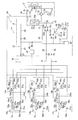
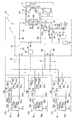
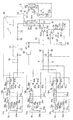
- FIG. It is a schematic block diagram of a refrigeration cycle system. It is a schematic functional block block diagram of the refrigeration cycle system 1.
- FIG. It is a figure which shows the operation (flow of a refrigerant) in a cooling operation of a refrigerating cycle system. It is a figure which shows the operation (flow of a refrigerant) in a heating operation of a refrigerating cycle system. It is a figure which shows the operation (the flow of a refrigerant) in the simultaneous cooling and heating operation (mainly cooling) of a refrigerating cycle system. It is a figure which shows the operation (the flow of a refrigerant) in the simultaneous cooling and heating operation (mainly heating) of a refrigerating cycle system.
- FIG. 1 is a schematic configuration diagram of the refrigeration cycle system 1.
- FIG. 2 is a schematic functional block configuration diagram of the refrigeration cycle system 1.
- the refrigeration cycle system 1 is a device used for heating and cooling indoors of buildings and the like by performing a steam compression refrigeration cycle operation.
- the refrigeration cycle system 1 has a primary side unit 5 and a secondary side unit 4 (corresponding to a refrigeration cycle device), and includes a dual refrigerant circuit that performs a dual refrigeration cycle.
- the primary side unit 5 has a vapor compression type primary side refrigerant circuit 5a (corresponding to the second cycle).
- R32 (corresponding to a heat medium) or the like is sealed in the primary side refrigerant circuit 5a as a refrigerant.
- the secondary side unit 4 has a vapor compression type secondary side refrigerant circuit 10 (corresponding to the first cycle). Carbon dioxide is sealed in the secondary side refrigerant circuit 10 as a refrigerant.
- the primary side unit 5 and the secondary side unit 4 are connected via a cascade heat exchanger 35, which will be described later.
- the secondary side unit 4 includes the first connection pipes 15a, 15b, 15c and the second connection pipes 16a, 16b, 16c corresponding to the plurality of branch units 6a, 6b, 6c corresponding to the plurality of utilization units 3a, 3b, 3c.
- the branch units 6a, 6b, 6c and the heat source unit 2 are connected via the three connecting pipes 7, 8 and 9.
- the plurality of utilization units 3a, 3b, and 3c are the first utilization unit 3a, the second utilization unit 3b, and the third utilization unit 3c.
- the plurality of branch units 6a, 6b, and 6c are the first branch unit 6a, the second branch unit 6b, and the third branch unit 6c.
- the heat source unit 2 is one in this embodiment.
- the three refrigerant connecting pipes are the first connecting pipe 8, the second connecting pipe 9, and the third connecting pipe 7.
- a refrigerant in a supercritical state, a refrigerant in a gas-liquid two-phase state, or a refrigerant in a gas state flows through the first connecting pipe 8 depending on the operating state.
- a refrigerant in a gas-liquid two-phase state or a refrigerant in a gas state flows through the second connecting pipe 9, depending on the operating state.
- a refrigerant in a supercritical state, a refrigerant in a gas-liquid two-phase state, or a refrigerant in a liquid state flows through the third connecting pipe 7, depending on the operating state.
- each of the utilization units 3a, 3b, and 3c can individually perform a cooling operation or a heating operation, and a refrigerant is supplied from the utilization unit that performs the heating operation to the utilization unit that performs the cooling operation. It is configured so that heat can be recovered between the units used by sending it. Specifically, in the present embodiment, heat recovery is performed by performing cooling-based operation or heating-based operation in which cooling operation and heating operation are performed at the same time. Further, in the refrigeration cycle system 1, the heat load of the heat source unit 2 is balanced according to the heat load of the entire plurality of utilization units 3a, 3b, and 3c in consideration of the above heat recovery (cooling main operation and heating main operation). It is configured as follows.
- the primary side unit 5 includes a primary side refrigerant circuit 5a, a primary side fan 75, and a primary side control unit 70.
- the primary side refrigerant circuit 5a includes a primary side compressor 71 (corresponding to a second compressor), a primary side switching mechanism 72, a primary side heat exchanger 74, a primary side expansion valve 76, and a secondary side refrigerant circuit 10. It has a cascade heat exchanger 35, which is shared with.
- the primary side refrigerant circuit 5a constitutes the primary side refrigerant circuit in the refrigeration cycle system 1, and a refrigerant such as R32 circulates inside.
- the primary side compressor 71 is a device for compressing the refrigerant on the primary side. For example, from a scroll type or other positive displacement compressor whose operating capacity can be changed by controlling the compressor motor 71a with an inverter. Become.
- the primary side switching mechanism 72 is the suction side of the primary side compressor 71 and the gas side of the primary side flow path 35b of the cascade heat exchanger 35.
- the fifth connection state is established (see the solid line of the primary side switching mechanism 72 in FIG. 1).
- the primary side switching mechanism 72 of the discharge side of the primary side compressor 71 and the primary side flow path 35b of the cascade heat exchanger 35 is established.
- a sixth connection state is established in which the gas side is connected (see the broken line of the primary side switching mechanism 72 in FIG. 1).
- the primary side switching mechanism 72 is a device capable of switching the flow path of the refrigerant in the primary side refrigerant circuit 5a, and includes, for example, a four-way switching valve. Then, by changing the switching state of the primary side switching mechanism 72, it is possible to make the cascade heat exchanger 35 function as an evaporator or a radiator of the refrigerant on the primary side.
- the cascade heat exchanger 35 is a device for allowing heat exchange between a refrigerant such as R32, which is a refrigerant on the primary side, and carbon dioxide, which is a refrigerant on the secondary side, without mixing with each other.
- the cascade heat exchanger 35 comprises, for example, a plate heat exchanger.
- the cascade heat exchanger 35 has a secondary side flow path 35a belonging to the secondary side refrigerant circuit 10 and a primary side flow path 35b belonging to the primary side refrigerant circuit 5a.
- the gas side of the secondary side flow path 35a is connected to the secondary side switching mechanism 22 via the third heat source pipe 25 (corresponding to the first flow path), and the liquid side thereof is the fourth heat source pipe 26 (second flow path). It is connected to the heat source side expansion valve 36 via (corresponding to).
- the gas side of the primary side flow path 35b is connected to the primary side compressor 71 via the primary side switching mechanism 72, and the liquid side thereof is connected to the primary side expansion valve 76.
- the primary side expansion valve 76 is provided in the liquid pipe between the cascade heat exchanger 35 and the primary side heat exchanger 74 of the primary side refrigerant circuit 5a.
- the primary side expansion valve 76 is an electric expansion valve capable of adjusting the opening degree, which adjusts the flow rate of the primary side refrigerant flowing through the liquid side portion of the primary side refrigerant circuit 5a.
- the primary side heat exchanger 74 is a device for exchanging heat between the primary side refrigerant and the room air, and includes, for example, a fin-and-tube heat exchanger composed of a large number of heat transfer tubes and fins. ..
- the primary side fan 75 is provided in the primary side unit 5, guides outdoor air to the primary side heat exchanger 74, exchanges heat with the primary side refrigerant flowing through the primary side heat exchanger 74, and then outdoors. Creates an air flow that causes the air to be discharged.
- the primary fan 75 is driven by the primary fan motor 75a.
- various sensors are provided on the primary side unit 5. Specifically, an outside air temperature sensor 77 that detects the temperature of the outdoor air before passing through the primary side heat exchanger 74, and a primary side discharge that detects the pressure of the primary side refrigerant discharged from the primary side compressor 71. A pressure sensor 78 is provided.
- the primary side control unit 70 controls the operations of the units 71 (71a), 72, 75 (75a), and 76 constituting the primary side unit 5.
- the primary side control unit 70 has a processor such as a CPU or a microcomputer provided for controlling the primary side unit 5 and a memory, and has a control signal or the like between the remote controller (not shown). And exchange of control signals and the like with the heat source side control unit 20 of the secondary side unit 4, the branch unit control units 60a, 60b, 60c, and the user side control units 50a, 50b, 50c. Can be done.
- the secondary side unit 4 is configured by connecting a plurality of utilization units 3a, 3b, 3c, a plurality of branch units 6a, 6b, 6c, and a heat source unit 2 to each other. ..
- Each utilization unit 3a, 3b, 3c is connected to the corresponding branch units 6a, 6b, 6c on a one-to-one basis.
- the utilization unit 3a and the branch unit 6a are connected via the first connection pipe 15a and the second connection pipe 16a
- the utilization unit 3b and the branch unit 6b are connected to the first connection pipe 15b and the second connection pipe. It is connected via 16b
- the utilization unit 3c and the branch unit 6c are connected via the first connection pipe 15c and the second connection pipe 16c.
- branch units 6a, 6b, and 6c are connected to each other via the heat source unit 2, the third connecting pipe 7, the first connecting pipe 8, and the second connecting pipe 9, which are three connecting pipes.
- the third connecting pipe 7, the first connecting pipe 8, and the second connecting pipe 9 extending from the heat source unit 2 are branched into a plurality of branches and are connected to the respective branch units 6a, 6b, and 6c. ing.
- the utilization units 3a, 3b, and 3c are installed in the ceiling of a building or the like by embedding or hanging them, or by hanging them on the wall surface of the room.
- the utilization units 3a, 3b, and 3c are connected to the heat source unit 2 via the connecting pipes 7, 8, and 9, and have utilization circuits 13a, 13b, and 13c that form a part of the secondary side refrigerant circuit 10. ing.
- the configurations of the utilization units 3a, 3b, and 3c will be described. Since the second utilization unit 3b and the third utilization unit 3c have the same configuration as the first utilization unit 3a, only the configuration of the first utilization unit 3a will be described here, and the second utilization unit 3b and the third utilization unit 3b will be described. Regarding the configuration of the utilization unit 3c, the subscript "b" or “c” is added instead of the subscript "a" of the code indicating each part of the first utilization unit 3a, and the description of each part will be omitted.
- the first utilization unit 3a mainly includes a utilization circuit 13a forming a part of the secondary side refrigerant circuit 10, an indoor fan 53a, and a utilization side control unit 50a.
- the indoor fan 53a has an indoor fan motor 54a.
- the second utilization unit 3b includes a utilization circuit 13b, an indoor fan 53b, a utilization side control unit 50b, and an indoor fan motor 54b.
- the third utilization unit 3c includes a utilization circuit 13c, an indoor fan 53c, a utilization side control unit 50c, and an indoor fan motor 54c.
- the utilization circuit 13a mainly includes a utilization side heat exchanger 52a (corresponding to a first heat exchanger), a first utilization pipe 57a, a second utilization pipe 56a, and a utilization side expansion valve 51a. ..
- the user-side heat exchanger 52a is a device for exchanging heat between the refrigerant and the indoor air, and includes, for example, a fin-and-tube heat exchanger composed of a large number of heat transfer tubes and fins.
- the utilization unit 3a has an indoor fan 53a that sucks indoor air into the unit, exchanges heat with the refrigerant flowing through the utilization side heat exchanger 52a, and then supplies the indoor air as supply air.
- the indoor fan 53a is driven by the indoor fan motor 54a.
- the plurality of utilization-side heat exchangers 52a, 52b, and 52c are connected in parallel to the secondary side switching mechanism 22, the suction flow path 23, and the cascade heat exchanger 35.
- One end of the second utilization pipe 56a is connected to the liquid side (opposite side to the gas side) of the utilization side heat exchanger 52a of the first utilization unit 3a.
- the other end of the second utilization pipe 56a is connected to the second connection pipe 16a.
- the above-mentioned utilization side expansion valve 51a is provided in the middle of the second utilization pipe 56a.
- the user-side expansion valve 51a is an electric expansion valve capable of adjusting the opening degree, which adjusts the flow rate of the refrigerant flowing through the user-side heat exchanger 52a.
- the utilization side expansion valve 51a is provided in the second utilization pipe 56a.
- One end of the first utilization pipe 57a is connected to the gas side of the utilization side heat exchanger 52a of the first utilization unit 3a.
- the first utilization pipe 57a is connected to the side opposite to the utilization side expansion valve 51a side of the utilization side heat exchanger 52a.
- the other end of the first utilization pipe 57a is connected to the first connection pipe 15a.
- various sensors are provided in the utilization unit 3a. Specifically, a liquid-side temperature sensor 58a that detects the temperature of the refrigerant on the liquid side of the user-side heat exchanger 52a is provided. Further, the utilization unit 3a is provided with an indoor temperature sensor 55a that detects an indoor temperature which is air taken in from the room and is the temperature of the air before passing through the utilization side heat exchanger 52a.
- the user-side control unit 50a controls the operations of the units 51a and 53a (54a) constituting the utilization unit 3a.
- the user-side control unit 50a has a processor such as a CPU or a microcomputer provided for controlling the user unit 3a and a memory, and receives a control signal or the like between the remote controller (not shown).
- a processor such as a CPU or a microcomputer provided for controlling the user unit 3a and a memory
- the branch unit control units 60a, 60b, 60c, and the primary side control unit 70 of the primary side unit 5. Can be done.
- Branch unit 6a, 6b, and 6c are connected to the utilization units 3a, 3b, and 3c in a one-to-one correspondence, and are installed in the space behind the ceiling in a building or the like. There is.
- the branch units 6a, 6b, 6c are connected to the heat source unit 2 via the connecting pipes 7, 8 and 9.
- the branch units 6a, 6b, and 6c have branch circuits 14a, 14b, and 14c that form a part of the secondary refrigerant circuit 10.
- the configurations of the branch units 6a, 6b, and 6c will be described. Since the second branch unit 6b and the third branch unit 6c have the same configuration as the first branch unit 6a, only the configuration of the first branch unit 6a will be described here, and the second branch unit 6b and the third branch unit 6b and the third branch unit 6b will be described. Regarding the configuration of the branch unit 6c, the subscript "b" or “c” is added instead of the subscript "a" of the code indicating each part of the first branch unit 6a, and the description of each part will be omitted.
- the first branch unit 6a mainly has a branch circuit 14a forming a part of the secondary side refrigerant circuit 10 and a branch unit control unit 60a.
- the second branch unit 6b has a branch circuit 14b and a branch unit control unit 60b.
- the third branch unit 6c has a branch circuit 14c and a branch unit control unit 60c.
- the branch circuit 14a mainly includes a merging pipe 62a, a first branch pipe 63a, a second branch pipe 64a, a first control valve 66a, a second control valve 67a, and a third branch pipe 61a. ing.
- One end of the merging pipe 62a is connected to the first connecting pipe 15a.
- a first branch pipe 63a and a second branch pipe 64a are branched and connected to the other end of the merging pipe 62a.
- the side of the first branch pipe 63a opposite to the merging pipe 62 side is connected to the first connecting pipe 8.
- the first branch pipe 63a is provided with a first control valve 66a that can be opened and closed.
- the first control valve 66a an electric expansion valve capable of adjusting the opening degree is adopted, but an electromagnetic valve or the like capable of opening and closing only may be adopted.
- the side of the second branch pipe 64a opposite to the merging pipe 62 side is connected to the second connecting pipe 9.
- the second branch pipe 64a is provided with a second control valve 67a that can be opened and closed.
- the second control valve 67a an electric expansion valve capable of adjusting the opening degree is adopted, but an electromagnetic valve or the like capable of only opening and closing may be adopted.
- One end of the third branch pipe 61a is connected to the second connection pipe 16a.
- the other end of the third branch pipe 61a is connected to the third connecting pipe 7.
- the first branch unit 6a can function as follows by opening the first control valve 66a and the second control valve 67a when performing the cooling operation described later.
- the first branch unit 6a sends the refrigerant flowing into the third branch pipe 61a through the third connecting pipe 7 to the second connecting pipe 16a.
- the refrigerant flowing through the second utilization pipe 56a of the first utilization unit 3a through the second connection pipe 16a is sent to the utilization side heat exchanger 52a of the first utilization unit 3a through the utilization side expansion valve 51a.
- the refrigerant sent to the utilization side heat exchanger 52a evaporates by heat exchange with the indoor air, and then flows through the first connection pipe 15a via the first utilization pipe 57a.
- the refrigerant that has flowed through the first connecting pipe 15a is sent to the merging pipe 62a of the first branch unit 6a.
- the refrigerant that has flowed through the merging pipe 62a branches into the first branch pipe 63a and the second branch pipe 64a.
- the refrigerant that has passed through the first control valve 66a in the first branch pipe 63a is sent to the first connecting pipe 8.
- the refrigerant that has passed through the second control valve 67a in the second branch pipe 64a is sent to the second connecting pipe 9.
- the first branch unit 6a keeps the first control valve 66a closed when the first utilization unit 3a cools the room when the cooling main operation and the heating main operation described later are performed.
- the function can be as follows.
- the first branch unit 6a sends the refrigerant flowing into the third branch pipe 61a through the third connecting pipe 7 to the second connecting pipe 16a.
- the refrigerant flowing through the second utilization pipe 56a of the first utilization unit 3a through the second connection pipe 16a is sent to the utilization side heat exchanger 52a of the first utilization unit 3a through the utilization side expansion valve 51a.
- the refrigerant sent to the utilization side heat exchanger 52a evaporates by heat exchange with the indoor air, and then flows through the first connection pipe 15a via the first utilization pipe 57a.
- the refrigerant that has flowed through the first connecting pipe 15a is sent to the merging pipe 62a of the first branch unit 6a.
- the refrigerant that has flowed through the merging pipe 62a flows into the second branch pipe 64a, passes through the second control valve 67a, and is then sent to the second connecting pipe 9.
- the second control valve 67a is opened or closed according to the operating condition as described later, and the first control valve 66a is opened.
- the first branch unit 6a the refrigerant flowing into the first branch pipe 63a through the first connecting pipe 8 passes through the first control valve 66a and is sent to the merging pipe 62a.
- the refrigerant that has flowed through the merging pipe 62a flows through the first utilization pipe 57a of the utilization unit 3a via the first connection pipe 15a and is sent to the utilization side heat exchanger 52a.
- the refrigerant sent to the utilization side heat exchanger 52a dissipates heat by heat exchange with the indoor air, and then passes through the utilization side expansion valve 51a provided in the second utilization pipe 56a.
- the refrigerant that has passed through the second utilization pipe 56a flows through the third branch pipe 61a of the first branch unit 6a via the second connection pipe 16a, and then is sent to the third connecting pipe 7.
- the first branch unit 6a closes the second control valve 67a when the first utilization unit 3a heats the room when the cooling main operation and the heating main operation described later are performed.
- the function can be as follows.
- the refrigerant flowing into the first branch pipe 63a through the first connecting pipe 8 passes through the first control valve 66a and is sent to the merging pipe 62a.
- the refrigerant that has flowed through the merging pipe 62a flows through the first utilization pipe 57a of the utilization unit 3a via the first connection pipe 15a and is sent to the utilization side heat exchanger 52a.
- the refrigerant sent to the utilization side heat exchanger 52a dissipates heat by heat exchange with the indoor air, and then passes through the utilization side expansion valve 51a provided in the second utilization pipe 56a.
- the refrigerant that has passed through the second utilization pipe 56a flows through the third branch pipe 61a of the first branch unit 6a via the second connection pipe 16a, and then is sent to the third connecting pipe 7.
- Such a function has not only the first branch unit 6a but also the second branch unit 6b and the third branch unit 6c. Therefore, the first branch unit 6a, the second branch unit 6b, and the third branch unit 6c each function as a refrigerant evaporator for each of the user side heat exchangers 52a, 52b, and 52c. , It is possible to switch individually whether to function as a refrigerant radiator.
- the branch unit control unit 60a controls the operations of the units 66a and 67a constituting the branch unit 6a.
- the branch unit control unit 60a has a processor such as a CPU or a microcomputer provided for controlling the branch unit 6a and a memory, and receives a control signal or the like between the remote controller (not shown). It is possible to exchange control signals and the like with the heat source side control unit 20 of the secondary side unit 4, the utilization units 3a, 3b, 3c, and the primary side control unit 70 of the primary side unit 5. It has become like.
- the heat source unit 2 is installed in a space different from the space in which the utilization units 3a, 3b, 3c and the branch units 6a, 6b, 6c are arranged, on the rooftop, or the like.
- the heat source unit 2 is connected to the branch units 6a, 6b, 6c via the connecting pipes 7, 8 and 9, and constitutes a part of the secondary side refrigerant circuit 10.
- the heat source unit 2 mainly includes a heat source circuit 12 that forms a part of the secondary side refrigerant circuit 10, and a heat source side control unit 20.
- the heat source circuit 12 mainly includes a secondary side compressor 21 (corresponding to the first compressor), a secondary side switching mechanism 22 (corresponding to the switching mechanism), a first heat source pipe 28, and a second heat source pipe 29.
- the suction flow path 23 (corresponding to the third flow path), the discharge flow path 24, the third heat source pipe 25 (corresponding to the first flow path), and the fourth heat source pipe 26 (corresponding to the second flow path).
- the fifth heat source pipe 27 the cascade heat exchanger 35, the heat source side expansion valve 36 (corresponding to the first expansion valve), the third closing valve 31, the first closing valve 32, and the second closing valve 33. It has an accumulator 30, an oil separator 34, an oil return circuit 40, a connection flow path 45, and a bypass flow path 47.
- the heat source circuit 12 may not have a refrigerant container such as a receiver for storing the refrigerant on the secondary side between the cascade heat exchanger 35 and the third closing valve 31.
- the secondary side compressor 21 is a device for compressing the refrigerant on the secondary side.
- positive displacement compression such as a scroll type capable of varying the operating capacity by controlling the compressor motor 21a with an inverter. It consists of a machine.
- the secondary compressor 21 is controlled so that the larger the load, the larger the operating capacity, depending on the load during operation.
- a compressor 21 having a structure in which the refrigerant cannot or is substantially unable to flow between the discharge side and the suction side when stopped can be used.
- the secondary side switching mechanism 22 is a mechanism capable of switching the connection state of the secondary side refrigerant circuit 10, particularly the flow path of the refrigerant in the heat source circuit 12.
- the secondary side switching mechanism 22 is configured by providing four switching valves 22a, 22b, 22c, and 22d, which are two-way valves, side by side in an annular flow path.
- the secondary side switching mechanism 22 instead of this, a combination of a plurality of three-way switching valves may be used.
- the secondary side switching mechanism 22 is a flow that connects the first switching valve 22a provided in the flow path connecting the discharge flow path 24 and the third heat source pipe 25, and the discharge flow path 24 and the first heat source pipe 28.
- the second switching valve 22b provided in the path, the third switching valve 22c provided in the flow path connecting the suction flow path 23 and the third heat source pipe 25, the suction flow path 23, and the first heat source pipe 28. It has a fourth switching valve 22d provided in the flow path connecting the two.
- the first switching valve 22a, the second switching valve 22b, the third switching valve 22c, and the fourth switching valve 22d are solenoid valves that can switch between the open state and the closed state, respectively.
- the secondary side switching mechanism 22 opens the first switching valve 22a and cascade heat with the discharge side of the secondary compressor 21.
- the first connection state is set in which the third switching valve 22c is closed while connecting to the gas side of the secondary side flow path 35a of the exchanger 35.
- the secondary side switching mechanism 22 opens the third switching valve 22c to the suction side of the secondary compressor 21.
- the second connection state is set in which the first switching valve 22a is closed while connecting to the gas side of the secondary side flow path 35a of the cascade heat exchanger 35.
- the secondary side switching mechanism 22 opens the second switching valve 22b and compresses the secondary side.
- the third connection state is set in which the fourth switching valve 22d is closed while connecting the discharge side of the machine 21 and the first connecting pipe 8.
- the secondary side switching mechanism 22 opens the fourth switching valve 22d and opens the first connecting pipe 8 and the secondary side. While connecting to the suction side of the compressor 21, the second switching valve 22b is closed in the fourth connection state.
- the cascade heat exchanger 35 is a device for allowing heat exchange between a refrigerant such as R32, which is a primary side refrigerant, and carbon dioxide, which is a secondary side refrigerant, without mixing with each other.
- the cascade heat exchanger 35 includes a secondary side flow path 35a through which the secondary side refrigerant of the secondary side refrigerant circuit 10 flows, and a primary side flow path 35b through which the primary side refrigerant of the primary side refrigerant circuit 5a flows. Is shared by the primary side unit 5 and the heat source unit 2.
- the cascade heat exchanger 35 is arranged inside the casing (not shown) of the heat source unit 2, and the refrigerant pipes extending from both ends of the primary side flow path 35b of the cascade heat exchanger 35 are provided. It is provided so as to extend to the outside of the casing (not shown) of the heat source unit 2.
- the heat source side expansion valve 36 is an electric expansion valve connected to the liquid side of the cascade heat exchanger 35 and capable of adjusting the opening degree in order to adjust the flow rate of the refrigerant on the secondary side flowing through the cascade heat exchanger 35. Is.
- the third closing valve 31, the first closing valve 32, and the second closing valve 33 are valves provided at connection ports with external equipment / piping (specifically, connecting pipes 7, 8 and 9). Specifically, the third closing valve 31 is connected to a third connecting pipe 7 drawn from the heat source unit 2. The first closing valve 32 is connected to a first connecting pipe 8 drawn from the heat source unit 2. The second closing valve 33 is connected to a second connecting pipe 9 drawn from the heat source unit 2.
- the first heat source pipe 28 is a refrigerant pipe that connects the first closing valve 32 and the secondary side switching mechanism 22. Specifically, the first heat source pipe 28 connects the first closing valve 32 and the portion of the secondary side switching mechanism 22 between the second switching valve 22b and the fourth switching valve 22d. There is.
- the suction flow path 23 is a flow path that connects the secondary side switching mechanism 22 and the suction side of the secondary side compressor 21. Specifically, the suction flow path 23 has a portion between the third switching valve 22c and the fourth switching valve 22d of the secondary side switching mechanism 22 and the suction side of the secondary side compressor 21. You are connected. An accumulator 30 is provided in the middle of the suction flow path 23.
- the second heat source pipe 29 is a refrigerant pipe that connects the second closing valve 33 and the middle of the suction flow path 23.
- the second heat source pipe 29 is a portion of the suction flow path 23 between the second switching valve 22b and the fourth switching valve 22d in the secondary side switching mechanism 22, and the accumulator 30. It is connected to the suction flow path 23 at the connection point Y, which is a portion between them.
- the discharge flow path 24 is a refrigerant pipe that connects the discharge side of the secondary side compressor 21 and the secondary side switching mechanism 22. Specifically, the discharge flow path 24 has a discharge side of the secondary side compressor 21 and a portion of the secondary side switching mechanism 22 between the first switching valve 22a and the second switching valve 22b. You are connected.
- the third heat source pipe 25 is a refrigerant pipe that connects the secondary side switching mechanism 22 and the gas side of the cascade heat exchanger 35.
- the third heat source pipe 25 includes a portion of the secondary side switching mechanism 22 between the first switching valve 22a and the third switching valve 22c and the secondary side flow path in the cascade heat exchanger 35. It is connected to the gas side end of 35a.
- the fourth heat source pipe 26 connects the liquid side of the cascade heat exchanger 35 (the side opposite to the gas side, the side opposite to the side where the secondary side switching mechanism 22 is provided) and the heat source side expansion valve 36. It is a refrigerant pipe. Specifically, the fourth heat source pipe 26 connects the liquid side end (the end opposite to the gas side) of the secondary side flow path 35a in the cascade heat exchanger 35 and the heat source side expansion valve 36. doing.
- the fifth heat source pipe 27 is a refrigerant pipe that connects the heat source side expansion valve 36 and the third closing valve 31.
- the accumulator 30 is a container capable of storing the refrigerant on the secondary side, and is provided on the suction side of the compressor 21 on the secondary side.
- the oil separator 34 is provided in the middle of the discharge flow path 24.
- the oil separator 34 is a device for separating the refrigerating machine oil discharged from the secondary compressor 21 along with the secondary refrigerant from the secondary refrigerant and returning it to the secondary compressor 21. ..
- the oil return circuit 40 is provided so as to connect the oil separator 34 and the suction flow path 23.
- the oil return circuit 40 extends so that the flow path extending from the oil separator 34 joins the portion of the suction flow path 23 between the accumulator 30 and the suction side of the secondary compressor 21. It has a flow path 41.
- An oil return capillary tube 42 and an oil return on-off valve 44 are provided in the middle of the oil return flow path 41.
- the oil return on-off valve 44 maintains the open state for a predetermined time and the closed state for a predetermined time when the secondary side compressor 21 is in the operating state in the secondary side refrigerant circuit 10. By repeating this, the amount of refrigerating machine oil returned through the oil return circuit 40 is controlled.
- the oil return on-off valve 44 is a solenoid valve whose opening and closing is controlled in the present embodiment, the oil return capillary tube 42 may be omitted while being an electric expansion valve capable of adjusting the opening degree.
- connection flow path 45 is provided so as to connect the fifth heat source pipe 27 and the suction flow path 23.
- the connection flow path 45 is provided so as to connect the fifth heat source pipe 27 and the portion of the suction flow path 23 between the secondary side switching mechanism 22 and the accumulator 30.
- a connection on-off valve 46 is provided in the middle of the connection flow path 45.
- the connection on-off valve 46 is a solenoid valve whose opening and closing is controlled in the present embodiment, it may be an electric expansion valve whose opening degree can be adjusted.
- the connection on-off valve 46 is controlled to be in the open state when the cooling operation or the cooling main operation, which will be described later, is stopped, and is in the closed state during the normal operation in which the secondary compressor 21 is driven. Is maintained at.
- the bypass flow path 47 is provided so as to connect the third heat source pipe 25 and the suction flow path 23.
- the bypass flow path 47 is provided so as to connect the third heat source pipe 25 and the portion of the suction flow path 23 between the secondary side switching mechanism 22 and the accumulator 30.
- a bypass capillary tube 48 (corresponding to a pressure reducing mechanism) and a bypass on-off valve 49 (corresponding to an on-off valve) are provided in the middle of the bypass flow path 47.
- the bypass on-off valve 49 is controlled to be in the open state when the heating operation or the heating main operation, which will be described later, is started, and is in the closed state during the normal operation in which the secondary compressor 21 is driven. Is maintained at.
- the bypass on-off valve 49 is a solenoid valve whose opening and closing is controlled in the present embodiment, the bypass capillary tube 48 may be omitted while being an electric expansion valve capable of adjusting the opening degree.
- the heat source unit 2 is provided with various sensors. Specifically, the secondary side suction pressure sensor 37 that detects the pressure of the secondary side refrigerant on the suction side of the secondary side compressor 21 (corresponding to the sensor that detects the refrigerant pressure or the refrigerant temperature in the third flow path).
- the secondary side discharge pressure sensor 38 that detects the pressure of the secondary side refrigerant on the discharge side of the secondary side compressor 21 and the temperature of the secondary side refrigerant on the discharge side of the secondary side compressor 21 are detected.
- a secondary side discharge temperature sensor 39 is provided.
- the heat source side control unit 20 controls the operations of each unit 21 (21a), 22, 36, 44, 46, 49 constituting the heat source unit 2.
- the heat source side control unit 20 has a processor such as a CPU or a microcomputer provided for controlling the heat source unit 2 and a memory, and the primary side control unit 70 and the utilization unit 3a of the primary side unit 5 are provided. Control signals and the like can be exchanged with the user-side control units 50a, 50b, 50c of 3b and 3c and the branch unit control units 60a, 60b, 60c.
- the heat source side control unit 20 the user side control units 50a, 50b, 50c, the branch unit control units 60a, 60b, 60c, and the primary side control unit 70 are wired or wireless.
- the control unit 80 is configured by being connected to each other so as to be able to communicate with each other. Therefore, the control unit 80 is based on the detection information of various sensors 37, 38, 39, 77, 78, 58a, 58b, 58c and the like and the instruction information received from the remote controller and the like (not shown).
- the refrigeration cycle operation of the refrigeration cycle system 1 can be mainly divided into a cooling operation, a heating operation, a cooling-based operation, and a heating-based operation.
- the utilization side heat exchanger functions as a refrigerant evaporator
- the cascade heat exchanger 35 is used as the secondary side refrigerant with respect to the evaporation load of the entire utilization unit. It is a refrigeration cycle operation that functions as a radiator of.
- the utilization side heat exchanger functions as a refrigerant radiator
- the cascade heat exchanger 35 is used as a secondary side refrigerant evaporator for the heat dissipation load of the entire utilization unit. It is a refrigeration cycle operation that functions as.
- the cooling main operation is an operation in which a utilization unit in which the utilization side heat exchanger functions as a refrigerant evaporator and a utilization unit in which the utilization side heat exchanger functions as a refrigerant radiator are mixed. be.
- the cascade heat exchanger 35 functions as a radiator of the refrigerant on the secondary side with respect to the evaporation load of the entire utilization unit. It is a cycle operation.
- the heating-based operation is an operation in which a utilization unit in which the utilization side heat exchanger functions as a refrigerant evaporator and a utilization unit in which the utilization side heat exchanger functions as a refrigerant radiator are mixed. be.
- the cascade heat exchanger 35 when the heat dissipation load is the main heat load of the entire utilization unit, the cascade heat exchanger 35 functions as an evaporator of the refrigerant on the secondary side with respect to the heat dissipation load of the entire utilization unit. It is a cycle operation.
- the operation of the refrigeration cycle system 1 including these refrigeration cycle operations is performed by the control unit 80 described above.
- one of the utilization units may be in the stopped state.
- the user units 3a, 3b, and 3c are controlled by the user-side control units 50a, 50b, and 50c that have received commands from a remote controller or the like (not shown) to be in an operation stopped state.
- the utilization units 3a, 3b, and 3c are in a state in which the utilization side expansion valves 51a, 51b, 51c are closed or the first control valves 66a, 66b, 66c and the second control valves 67a, 67b, 67c are closed when the operation is stopped. Then, the indoor fans 53a, 53b, and 53c are stopped. As a result, the flow of the refrigerant in the utilization units 3a, 3b, and 3c in the stopped operation state is interrupted.
- Cooling operation for example, all of the heat exchangers 52a, 52b, and 52c on the user side of the utilization units 3a, 3b, and 3c function as refrigerant evaporators, and the cascade heat exchanger 35 Operates to function as a radiator for the refrigerant on the secondary side.
- the primary side refrigerant circuit 5a and the secondary side refrigerant circuit 10 of the refrigeration cycle system 1 are configured as shown in FIG.
- the arrow attached to the primary side refrigerant circuit 5a and the arrow attached to the secondary side refrigerant circuit 10 in FIG. 3 indicate the flow of the refrigerant during the cooling operation.
- the cascade heat exchanger 35 functions as an evaporator of the refrigerant on the primary side by switching the primary side switching mechanism 72 to the fifth connection state.
- the fifth connection state of the primary side switching mechanism 72 is the connection state shown by the solid line in the primary side switching mechanism 72 of FIG.
- the refrigerant on the primary side condensed in the primary side heat exchanger 74 is depressurized in the primary side expansion valve 76, then flows through the primary side flow path 35b of the cascade heat exchanger 35 and evaporates, and passes through the primary side switching mechanism 72. Then, it is sucked into the primary side compressor 71.
- the cascade heat exchanger 35 is made to function as a radiator of the refrigerant on the secondary side by switching the secondary side switching mechanism 22 to the first connection state and the fourth connection state. ing.
- the first connection state of the secondary side switching mechanism 22 is a connection state in which the first switching valve 22a is in the open state and the third switching valve 22c is in the closed state.
- the fourth connection state of the secondary side switching mechanism 22 is a connection state in which the fourth switching valve 22d is in the open state and the second switching valve 22b is in the closed state.
- the opening degree of the heat source side expansion valve 36 is adjusted.
- the first control valves 66a, 66b, 66c and the second control valves 67a, 67b, 67c are controlled to be in the open state.
- all of the user-side heat exchangers 52a, 52b, and 52c of the utilization units 3a, 3b, and 3c function as refrigerant evaporators.
- all of the utilization side heat exchangers 52a, 52b, 52c of the utilization units 3a, 3b and 3c and the suction side of the secondary side compressor 21 of the heat source unit 2 are the first utilization pipes 57a, 57b, 57c, the first.
- the secondary side high-pressure refrigerant compressed and discharged by the secondary side compressor 21 passes through the secondary side switching mechanism 22 to the secondary side flow path of the cascade heat exchanger 35. It is sent to 35a.
- the high-pressure refrigerant on the secondary side flowing through the secondary side flow path 35a dissipates heat, and the refrigerant on the primary side flowing through the primary side flow path 35b of the cascade heat exchanger 35 evaporates.
- the secondary refrigerant dissipated in the cascade heat exchanger 35 passes through the heat source side expansion valve 36 whose opening degree is adjusted, and then is sent to the third connecting pipe 7 through the third closing valve 31.
- the refrigerant sent to the third connecting pipe 7 is branched into three and passes through the third branch pipes 61a, 61b, 61c of the first to third branch units 6a, 6b, 6c, respectively.
- the refrigerant flowing through the second connection pipes 16a, 16b, 16c is sent to the second utilization pipes 56a, 56b, 56c of the first to third utilization units 3a, 3b, 3c, respectively.
- the refrigerant sent to the second utilization pipes 56a, 56b, 56c is sent to the utilization side expansion valves 51a, 51b, 51c of the utilization units 3a, 3b, 3c.
- the refrigerant that has passed through the utilization-side expansion valves 51a, 51b, 51cc whose opening degree is adjusted is the indoor air and heat supplied by the indoor fans 53a, 53b, 53c in the utilization-side heat exchangers 52a, 52b, 52c. Make a replacement.
- the refrigerant flowing through the heat exchangers 52a, 52b, and 52c on the utilization side evaporates and becomes a low-pressure gas refrigerant.
- the indoor air is cooled and supplied to the room. As a result, the indoor space is cooled.
- the low-pressure gas refrigerant evaporated in the user-side heat exchangers 52a, 52b, 52c flows through the first utilization pipes 57a, 57b, 57c, flows through the first connection pipes 15a, 15b, 15c, and then flows through the first to third pipes. It is sent to the merging pipes 62a, 62b, 62c of the branch units 6a, 6b, 6c.
- the low-pressure gas refrigerant sent to the merging pipes 62a, 62b, 62c branches into the first branch pipes 63a, 63b, 63c and the second branch pipes 64a, 64b, 64c and flows.
- the refrigerant that has passed through the first control valves 66a, 66b, 66c in the first branch pipes 63a, 63b, 63c is sent to the first connecting pipe 8.
- the refrigerant that has passed through the second control valves 67a, 67b, 67c in the second branch pipes 64a, 64b, 64c is sent to the second connecting pipe 9.
- the low-pressure gas refrigerant sent to the first connecting pipe 8 and the second connecting pipe 9 is the first closing valve 32, the second closing valve 33, the first heat source pipe 28, the second heat source pipe 29, and the secondary side. It is returned to the suction side of the secondary compressor 21 through the switching mechanism 22, the suction flow path 23, and the accumulator 30.
- the cascade heat exchanger 35 is made to function as a radiator of the refrigerant on the primary side by switching the primary side switching mechanism 72 to the sixth operating state.
- the sixth operating state of the primary side switching mechanism 72 is the connection state shown by the broken line in the primary side switching mechanism 72 of FIG.
- the refrigerant on the primary side condensed in the cascade heat exchanger 35 is depressurized by the expansion valve 76 on the primary side, and then evaporated by exchanging heat with the outside air supplied from the fan 75 on the primary side in the primary heat exchanger 74. , It is sucked into the primary side compressor 71 via the primary side switching mechanism 72.
- the secondary side switching mechanism 22 is switched to the second connection state and the third connection state.
- the cascade heat exchanger 35 functions as an evaporator of the refrigerant on the secondary side.
- the second connection state of the secondary side switching mechanism 22 is a connection state in which the first switching valve 22a is in the closed state and the third switching valve 22c is in the open state.
- the third connection state of the secondary side switching mechanism 22 is a connection state in which the second switching valve 22b is in the open state and the fourth switching valve 22d is in the closed state. Further, the opening degree of the heat source side expansion valve 36 is adjusted.
- the first control valves 66a, 66b, 66c are controlled to be in the open state, and the second control valves 67a, 67b, 67c are controlled to be in the closed state.
- all of the user-side heat exchangers 52a, 52b, and 52c of the utilization units 3a, 3b, and 3c function as refrigerant radiators.
- the utilization side heat exchangers 52a, 52b, 52c of the utilization units 3a, 3b and 3c and the discharge side of the secondary side compressor 21 of the heat source unit 2 are the discharge flow path 24, the first heat source pipe 28, and the first.
- the opening degrees of the utilization side expansion valves 51a, 51b, and 51c are adjusted.
- the plurality of utilization units 3a, 3b, and 3c may include the utilization units in the stopped operation state.
- the high-pressure refrigerant compressed and discharged by the secondary side compressor 21 is a first heat source through the second switching valve 22b controlled to be in the open state by the secondary side switching mechanism 22. It is sent to the pipe 28.
- the refrigerant sent to the first heat source pipe 28 is sent to the first connecting pipe 8 through the first closing valve 32.
- the high-pressure refrigerant sent to the first connecting pipe 8 is branched into three and sent to the first branch pipes 63a, 63b, 63c of the utilization units 3a, 3b, and 3c which are the utilization units during operation. ..
- the high-pressure refrigerant sent to the first branch pipes 63a, 63b, 63c passes through the first control valves 66a, 66b, 66c and flows through the merging pipes 62a, 62b, 62c. After that, the refrigerant flowing through the first connection pipes 15a, 15b, 15c and the first utilization pipes 57a, 57b, 57c is sent to the utilization side heat exchangers 52a, 52b, 52c.
- the high-pressure refrigerant sent to the user-side heat exchangers 52a, 52b, 52c exchanges heat with the indoor air supplied by the indoor fans 53a, 53b, 53c in the user-side heat exchangers 52a, 52b, 52c. ..
- the refrigerant flowing through the user-side heat exchangers 52a, 52b, and 52c dissipates heat.
- the indoor air is heated and supplied to the room. As a result, the indoor space is heated.
- the refrigerant dissipated in the user-side heat exchangers 52a, 52b, 52c flows through the second utilization pipes 56a, 56b, 56c and passes through the utilization-side expansion valves 51a, 51b, 51c whose opening degree is adjusted. After that, the refrigerant that has flowed through the second connection pipes 16a, 16b, 16c flows through the third branch pipes 61a, 61b, 61c of the branch units 6a, 6b, 6c.
- the refrigerant sent to the third branch pipes 61a, 61b, 61c is sent to the third connecting pipe 7 and merges.
- the refrigerant sent to the third connecting pipe 7 is sent to the heat source side expansion valve 36 through the third closing valve 31.
- the refrigerant sent to the heat source side expansion valve 36 is sent to the cascade heat exchanger 35 after the flow rate is adjusted by the heat source side expansion valve 36.
- the refrigerant on the secondary side flowing through the secondary side flow path 35a evaporates to become a low-pressure gas refrigerant and is sent to the secondary side switching mechanism 22, and the primary side flow of the cascade heat exchanger 35.
- the refrigerant on the primary side flowing through the path 35b condenses.
- the low-pressure gas refrigerant on the secondary side sent to the secondary side switching mechanism 22 is returned to the suction side of the secondary compressor 21 through the suction flow path 23 and the accumulator 30.
- the utilization-side heat exchangers 52a and 52b of the utilization units 3a and 3b function as refrigerant evaporators
- the utilization-side heat exchanger 52c of the utilization unit 3c Operates to function as a refrigerant radiator.
- the cascade heat exchanger 35 functions as a radiator for the refrigerant on the secondary side.
- the primary side refrigerant circuit 5a and the secondary side refrigerant circuit 10 of the refrigeration cycle system 1 are configured as shown in FIG.
- the arrows attached to the primary side refrigerant circuit 5a and the arrows attached to the secondary side refrigerant circuit 10 in FIG. 5 indicate the flow of the refrigerant during the cooling main operation.
- the cascade heat exchanger 35 is switched by switching the primary side switching mechanism 72 to the fifth connection state (the state shown by the solid line of the primary side switching mechanism 72 in FIG. 5). It is designed to function as an evaporator for the refrigerant on the primary side.
- the refrigerant on the primary side discharged from the primary side compressor 71 passes through the primary side switching mechanism 72, and the outside air supplied from the primary side fan 75 in the primary side heat exchanger 74. It condenses by exchanging heat with.
- the refrigerant on the primary side condensed in the primary side heat exchanger 74 is depressurized in the primary side expansion valve 76, then flows through the primary side flow path 35b of the cascade heat exchanger 35 and evaporates, and passes through the primary side switching mechanism 72. Then, it is sucked into the primary side compressor 71.
- the secondary side switching mechanism 22 is connected in the first connection state (the first switching valve 22a is in the open state and the third switching valve 22c is in the closed state) and in the third connection state (second switching valve 22b).
- the cascade heat exchanger 35 functions as a radiator of the refrigerant on the secondary side by switching to the closed state of the fourth switching valve 22d in the open state. Further, the opening degree of the heat source side expansion valve 36 is adjusted.
- the first control valve 66c and the second control valves 67a, 67b are controlled to be in the open state, and the first control valves 66a, 66b, and the first 2
- the control valve 67c is controlled to be closed.
- the utilization side heat exchangers 52a and 52b of the utilization units 3a and 3b function as refrigerant evaporators
- the utilization side heat exchangers 52c of the utilization unit 3c function as refrigerant radiators.
- the heat exchangers 52a and 52b on the use side of the use units 3a and 3b and the suction side of the secondary compressor 21 of the heat source unit 2 are connected to each other via the second connecting pipe 9, and are used.
- the user-side heat exchanger 52c of the unit 3c and the discharge side of the secondary compressor 21 of the heat source unit 2 are connected to each other via the first connecting pipe 8.
- the opening degrees of the utilization side expansion valves 51a, 51b, and 51c are adjusted.
- the plurality of utilization units 3a, 3b, and 3c may include the utilization units in the stopped operation state.
- a part of the secondary side high-pressure refrigerant compressed and discharged by the secondary side compressor 21 is the secondary side switching mechanism 22, the first heat source pipe 28, and the second. 1 It is sent to the first connecting pipe 8 through the closing valve 32, and the rest is sent to the secondary side flow path 35a of the cascade heat exchanger 35 through the secondary side switching mechanism 22 and the third heat source pipe 25.
- the high-pressure refrigerant sent to the first connecting pipe 8 is sent to the first branch pipe 63c.
- the high-pressure refrigerant sent to the first branch pipe 63c is sent to the user side heat exchanger 52c of the utilization unit 3c through the first control valve 66c and the merging pipe 62c.
- the high-pressure refrigerant sent to the user-side heat exchanger 52c exchanges heat with the indoor air supplied by the indoor fan 53c in the user-side heat exchanger 52c.
- the refrigerant flowing through the user side heat exchanger 52c dissipates heat.
- the indoor air is heated and supplied into the room to perform the heating operation of the utilization unit 3c.
- the refrigerant dissipated in the user-side heat exchanger 52c flows through the second utilization pipe 56c, and the flow rate is adjusted in the utilization-side expansion valve 51c. After that, the refrigerant flowing through the second connecting pipe 16c is sent to the third branch pipe 61c of the branch unit 6c.
- the high-pressure refrigerant sent to the secondary side flow path 35a of the cascade heat exchanger 35 dissipates heat by exchanging heat with the primary side refrigerant flowing through the primary side flow path 35b in the cascade heat exchanger 35.
- the secondary refrigerant dissipated in the cascade heat exchanger 35 is sent to the third connecting pipe 7 through the third closing valve 31 after the flow rate is adjusted in the heat source side expansion valve 36, and is sent to the third connecting pipe 7 to the user side heat exchanger 52c. It merges with the radiated refrigerant in.
- the refrigerant merged in the third connecting pipe 7 is branched into two and sent to the third branch pipes 61a and 61b of the branch units 6a and 6b, respectively.
- the refrigerant flowing through the second connection pipes 16a and 16b is sent to the second utilization pipes 56a and 56b of the first and second utilization units 3a and 3b, respectively.
- the refrigerant flowing through the second utilization pipes 56a and 56b passes through the utilization side expansion valves 51a and 51b of the utilization units 3a and 3b.
- the refrigerant that has passed through the utilization-side expansion valves 51a and 51b whose opening degree is adjusted exchanges heat with the indoor air supplied by the indoor fans 53a and 53b in the utilization-side heat exchangers 52a and 52b.
- the refrigerant flowing through the heat exchangers 52a and 52b on the utilization side evaporates and becomes a low-pressure gas refrigerant.
- the indoor air is cooled and supplied to the room.
- the indoor space is cooled.
- the low-pressure gas refrigerant evaporated in the user-side heat exchangers 52a and 52b is sent to the merging pipes 62a and 62b of the first and second branch units 6a and 6b.
- the low-pressure gas refrigerant sent to the merging pipes 62a and 62b is sent to the second connecting pipe 9 through the second control valves 67a and 67b and the second branch pipes 64a and 64b and merges.
- the low-pressure gas refrigerant sent to the second connecting pipe 9 is returned to the suction side of the secondary compressor 21 through the second closing valve 33, the second heat source pipe 29, the suction flow path 23, and the accumulator 30. ..
- the utilization-side heat exchangers 52a and 52b of the utilization units 3a and 3b function as refrigerant radiators, and the utilization-side heat exchanger 52c evaporates the refrigerant. Operate to function as a vessel.
- the cascade heat exchanger 35 functions as an evaporator of the refrigerant on the secondary side.
- the primary side refrigerant circuit 5a and the secondary side refrigerant circuit 10 of the refrigeration cycle system 1 are configured as shown in FIG.
- the arrows attached to the primary side refrigerant circuit 5a and the arrows attached to the secondary side refrigerant circuit 10 in FIG. 6 indicate the flow of the refrigerant during the main heating operation.
- the cascade heat exchanger 35 is made to function as a radiator of the refrigerant on the primary side by switching the primary side switching mechanism 72 to the sixth operating state.
- the sixth operating state of the primary side switching mechanism 72 is the connected state shown by the broken line in the primary side switching mechanism 72 of FIG.
- the refrigerant on the primary side condensed in the cascade heat exchanger 35 is depressurized by the expansion valve 76 on the primary side, and then evaporated by exchanging heat with the outside air supplied from the fan 75 on the primary side in the primary heat exchanger 74. , It is sucked into the primary side compressor 71 via the primary side switching mechanism 72.
- the secondary side switching mechanism 22 is switched to the second connection state and the third connection state.
- the second connection state of the secondary side switching mechanism 22 is a connection state in which the first switching valve 22a is in the closed state and the third switching valve 22c is in the open state.
- the third connection state of the secondary side switching mechanism 22 is a connection state in which the second switching valve 22b is in the open state and the fourth switching valve 22d is in the closed state.
- the first control valve 66a, 66b and the second control valve 67c are controlled to be in the open state, and the first control valve 66c and the second control valve 66c and the second control valve are controlled.
- the valves 67a and 67b are controlled to be closed.
- the utilization side heat exchangers 52a and 52b of the utilization units 3a and 3b function as a refrigerant radiator, and the utilization side heat exchanger 52c of the utilization unit 3c functions as a refrigerant evaporator.
- the utilization side heat exchanger 52c of the utilization unit 3c and the suction side of the secondary side compressor 21 of the heat source unit 2 are the first utilization pipe 57c, the first connection pipe 15c, the merging pipe 62c, and the second branch pipe 64c. , And the state of being connected via the second connecting pipe 9. Further, the utilization side heat exchangers 52a and 52b of the utilization units 3a and 3b and the discharge side of the secondary side compressor 21 of the heat source unit 2 are connected to the discharge flow path 24, the first heat source pipe 28, and the first connecting pipe 8.
- the plurality of utilization units 3a, 3b, and 3c may include the utilization units in the stopped operation state.
- the secondary side high-pressure refrigerant compressed and discharged by the secondary side compressor 21 passes through the secondary side switching mechanism 22, the first heat source pipe 28, and the first closing valve 32. , Is sent to the first communication pipe 8.
- the high-pressure refrigerant sent to the first connecting pipe 8 is branched into two, and the first branch is connected to each of the first utilization unit 3a and the second utilization unit 3b, which are the utilization units during operation. It is sent to the first branch pipes 63a and 63b of the unit 6a and the second branch unit 6b.
- the high-pressure refrigerant sent to the first branch pipes 63a and 63b passes through the first control valves 66a and 66b, the merging pipes 62a and 62b, and the first connection pipes 15a and 15b, and the first utilization unit 3a and the second utilization unit 3b. It is sent to the heat exchangers 52a and 52b on the user side.
- the high-pressure refrigerant sent to the user-side heat exchangers 52a and 52b exchanges heat with the indoor air supplied by the indoor fans 53a and 53b in the user-side heat exchangers 52a and 52b.
- the refrigerant flowing through the heat exchangers 52a and 52b on the user side dissipates heat.
- the indoor air is heated and supplied to the room.
- the indoor space is heated.
- the refrigerant dissipated in the user-side heat exchangers 52a and 52b flows through the second utilization pipes 56a and 56b and passes through the utilization-side expansion valves 51a and 51b whose opening degree is adjusted.
- the refrigerant flowing through the second connecting pipes 16a and 16b is sent to the third connecting pipe 7 via the third branch pipes 61a and 61b of the branch units 6a and 6b.
- the refrigerant sent to the third branch pipe 61c flows through the second utilization pipe 56c of the utilization unit 3c via the second connection pipe 16c and is sent to the utilization side expansion valve 51c.
- the refrigerant that has passed through the utilization-side expansion valve 51c whose opening degree is adjusted exchanges heat with the indoor air supplied by the indoor fan 53c in the utilization-side heat exchanger 52c.
- the refrigerant flowing through the user-side heat exchanger 52c evaporates and becomes a low-pressure gas refrigerant.
- the indoor air is cooled and supplied to the room.
- the indoor space is cooled.
- the low-pressure gas refrigerant evaporated in the user-side heat exchanger 52c passes through the first utilization pipe 57c and the first connection pipe 15c and is sent to the merging pipe 62c.
- the low-pressure gas refrigerant sent to the merging pipe 62c is sent to the second connecting pipe 9 through the second control valve 67c and the second branch pipe 64c.
- the low-pressure gas refrigerant sent to the second connecting pipe 9 is returned to the suction side of the secondary compressor 21 through the second closing valve 33, the second heat source pipe 29, the suction flow path 23, and the accumulator 30. ..
- the refrigerant sent to the heat source side expansion valve 36 passes through the heat source side expansion valve 36 whose opening degree is adjusted, and then passes through the primary side flow path 35b in the secondary side flow path 35a of the cascade heat exchanger 35. It exchanges heat with the flowing primary refrigerant.
- the refrigerant flowing through the secondary side flow path 35a of the cascade heat exchanger 35 evaporates to become a low-pressure gas refrigerant, which is sent to the secondary side switching mechanism 22.
- the low-pressure gas refrigerant sent to the secondary side switching mechanism 22 merges with the low-pressure gas refrigerant evaporated in the utilization side heat exchanger 52c in the suction flow path 23.
- the combined refrigerant is returned to the suction side of the secondary compressor 21 via the accumulator 30.
- the control unit 80 starts activation control when it receives an activation instruction from a remote controller (not shown).
- step S1 the control unit 80 controls the connection on-off valve 46, which is in the open state when the cooling operation is stopped or when the cooling main operation is stopped, in the closed state.
- the control unit 80 determines whether or not the first predetermined condition for starting the activation control is satisfied.
- the first predetermined condition is not particularly limited, but may be, for example, a condition that is determined to be satisfied when the temperature of the refrigerant in the suction flow path 23, the outside air temperature, or the like is equal to or higher than the predetermined temperature.
- the pressure equivalent saturation temperature grasped from the pressure detected by the secondary side suction pressure sensor 37 may be used.
- the temperature detected by the outside air temperature sensor 77 may be used.
- the process proceeds to step S3. If the first predetermined condition is not satisfied, the process proceeds to step S6.
- step S3 the control unit 80 activates the primary side compressor 71 with respect to the primary side unit 5 while keeping the primary side switching mechanism 72 in the fifth connected state (see the solid line of the primary side switching mechanism 72 in FIG. 1). Further, the control unit 80 controls the bypass on-off valve 49 in the open state of the secondary side unit 4 while the secondary side compressor 21 is in the stopped state. The control unit 80 keeps the oil return on-off valve 44 in the closed state.
- step S4 the control unit 80 determines whether or not the second predetermined condition is satisfied.
- the second predetermined condition may be a condition that is satisfied when the detection pressure of the secondary suction pressure sensor 37 is equal to or lower than the predetermined pressure, or the time elapsed from the start of the process of step S3 is the predetermined time. It may be a condition that is satisfied when it exceeds, or it may be a condition that is satisfied when either or both of these are satisfied.
- step S5 If the second predetermined condition is not satisfied, step S4 is repeated.
- step S5 the control unit 80 activates the secondary side compressor 21 while setting the connection state of the secondary side switching mechanism 22 to the connection state corresponding to the cooling operation or the refrigerant main operation described above. Further, the control unit 80 controls the bypass on-off valve 49 in the closed state. The control unit 80 ends the start-up control as described above, and thereafter executes the above-mentioned cooling operation or refrigerant-based operation.
- step S6 the control unit 80 activates the primary side compressor 71 with respect to the primary side unit 5 while keeping the primary side switching mechanism 72 in the fifth connected state. Further, the control unit 80 keeps the bypass on-off valve 49 in the closed state of the secondary side unit 4, and changes the connection state of the secondary side switching mechanism 22 to the above-mentioned cooling operation or the cooling main operation. At the same time, the secondary compressor 21 is started. The control unit 80 ends the start-up control as described above, and thereafter, executes the above-mentioned cooling operation or cooling main operation.
- carbon dioxide is used as the refrigerant in the secondary side refrigerant circuit 10, but the refrigerant pressure of this carbon dioxide refrigerant sharply rises due to the influence of the ambient temperature.
- Cheap In particular, when the operation is stopped and the ambient temperature such as the outside air temperature becomes a high temperature environment of 30 ° C. to 40 ° C. to 50 ° C., the refrigerant pressure suddenly increases in the region of the high-pressure refrigerant in the secondary side refrigerant circuit 10. There is a risk of rising.
- connection on-off valve 46 is controlled to be in the open state when the cooling operation or the cooling main operation is stopped, so that the region of the high-pressure refrigerant and the low-pressure refrigerant in the secondary side refrigerant circuit 10 Areas are connected to reduce the refrigerant pressure of the high-pressure refrigerant.
- connection on-off valve 46 is controlled to be in the open state and the high-pressure refrigerant is guided to the suction flow path 23 when the operation is stopped in this way, the refrigerant pressure in the suction flow path 23 tends to increase.
- the refrigerant in the suction flow path 23 which has a relatively high pressure, is further compressed, so that the refrigerant pressure on the discharge side of the secondary compressor 21 suddenly increases. There is a risk of rising to.
- the primary side compressor 71 is started before the secondary side compressor 21 is started, and the bypass on-off valve 49 is operated.
- the start control is performed to control the open state.
- the primary side flow path 35b in the cascade heat exchanger 35 functions as an evaporator of the primary side refrigerant, so that the temperature of the secondary side refrigerant in the secondary side flow path 35a can be lowered.
- the refrigerant in the suction flow path 23 has a bypass capillary tube 48 and a bypass flow path having a bypass on-off valve 49 controlled to be in an open state. It becomes possible to lead to the secondary side flow path 35a via the 47 and the third heat source pipe 25. This makes it possible to keep the refrigerant pressure on the secondary side in the suction flow path 23 low.
- the intake refrigerant suppressed to a relatively low pressure is compressed, so that the refrigerant pressure on the secondary side on the discharge side can also be suppressed to a low level. ..
- the secondary side flow path 35a, the third heat source pipe 25, and the fourth heat source pipe 26 are secondary. The pressure of the refrigerant on the next side is lowered, and it is possible to suppress the high pressure of the secondary refrigerant circuit 10 after the secondary compressor 21 is started to be low.
- the heat source circuit 12 of the present embodiment does not have a refrigerant container such as a receiver for storing the refrigerant on the secondary side between the cascade heat exchanger 35 and the third closing valve 31, and is a high-pressure refrigerant on the secondary side. It is a structure in which the pressure of the However, as described above, in the present embodiment, since the start-up control is performed, it is possible to prevent the high-pressure refrigerant on the secondary side from rising abnormally.
- the oil return circuit 40a may be adopted instead of the bypass flow path 47 and the oil return circuit 40 of the above embodiment.
- the oil return circuit 40a of the present embodiment has a first oil return flow path 41a and a second oil return flow path 43a that connect the oil separator 34 and the suction flow path 23 in parallel with each other.
- An oil return capillary tube 42a is provided in the first oil return flow path 41a.
- An oil return on-off valve 44a is provided in the second oil return flow path 43a. Similar to the oil return on-off valve 44 of the above embodiment, the oil return on-off valve 44a repeats maintaining the open state for a predetermined time and the closed state for a predetermined time, so that the refrigerating machine oil through the oil return circuit 40a can be used. It controls the amount of oil returned.
- the refrigerant on the secondary side in the suction flow path 23 is transferred to the first oil return flow path 41a having the oil return capillary tube 42a, the oil separator 34, the discharge flow path 24, and the secondary. It becomes possible to lead to the secondary side flow path 35a in the cascade heat exchanger 35 via the side switching mechanism 22 (the first switching valve 22a) and the third heat source pipe 25. This makes it possible to achieve the same effect as that of the above embodiment.
- connection on-off valve 46 in order to suppress an increase in the pressure of the high-pressure refrigerant in the secondary side refrigerant circuit 10 when the operation is stopped, the connection on-off valve 46 is controlled to be in an open state when the operation is stopped, whereby the refrigerant in the suction flow path 23 is controlled. It was explained by taking as an example that the pressure of the and, However, the refrigeration cycle system is not limited to a system in which the connection on-off valve 46 is controlled to be in an open state when stopped, and is also limited to a system in which the heat source circuit 12 has a connection flow path 45 and a connection on-off valve 46. I can't.
- the pressure of the secondary side refrigerant in the suction flow path 23 tends to increase. Therefore, the same problem as that of the above embodiment may occur.
- the accumulator 30 is provided in the middle of the suction flow path 23, the above-mentioned problem is likely to occur because the refrigerant in the accumulator 30 is affected by the ambient temperature. Even in these cases, it is possible to prevent the pressure of the carbon dioxide refrigerant from rising abnormally by performing a process of reducing the refrigerant pressure in the suction flow path 23 before starting the secondary compressor 21. can.
- the heat medium circulating in the primary side refrigerant circuit 5a is not particularly limited, and for example, brine, water, or the like may be used.
- the primary side refrigerant circuit 5a is not limited to the one in which the compression type refrigeration cycle is performed, and may be one in which brine or water as a low temperature source is supplied to the cascade heat exchanger 35.
- the secondary side refrigerant circuit 10 has a secondary side switching mechanism 22 for switching between a state in which the cascade heat exchanger 35 functions as a radiator for the refrigerant on the secondary side and a state in which the cascade heat exchanger 35 functions as a heat absorber. This was explained by taking the case of being present as an example.
- the secondary side refrigerant circuit 10 does not have to have the secondary side switching mechanism 22 as described above, and the cascade heat exchanger 35 is operated to function as a radiator of the secondary side refrigerant. Only may be possible.
- the bypass flow path 47 of the above embodiment may be connected to any location from the utilization side heat exchangers 52a, 52b, 52c to the suction side of the secondary side compressor 21. ..
- the heat source side expansion valve 36 provided in the heat source unit 2 the utilization side expansion valves 51a, 51b, 51c provided in the utilization units 3a, 3b, and 3c, and the branch units 6a, 6b, 6c are provided.
- the secondary side unit 4 having the first control valves 66a, 66b, 66c and the second control valves 67a, 67b, 67c, which have been obtained, has been described as an example.
- the secondary side unit 4 of the above embodiment may be configured as, for example, the secondary side unit 4a shown in FIG.
- the secondary side unit 4a is provided with a heat source side expansion mechanism 11 (corresponding to the first expansion portion) in the heat source unit 2 instead of the heat source side expansion valve 36 of the above embodiment.
- the heat source side expansion mechanism 11 is provided between the fourth heat source pipe 26 and the fifth heat source pipe 27.
- the heat source side expansion mechanism 11 has a first heat source side branch flow path 11a and a second heat source side branch flow path 11b, which are flow paths arranged in parallel with each other.
- the first heat source side expansion valve 17a and the first heat source side check valve 18a are provided side by side in the first heat source side branch flow path 11a.
- the second heat source side expansion valve 17b and the second heat source side check valve 18b are provided side by side in the second heat source side branch flow path 11b.
- the first heat source side expansion valve 17a and the second heat source side expansion valve 17b are both electric expansion valves whose opening degree can be adjusted.
- the first heat source side check valve 18a is a check valve that allows only the refrigerant flow flowing from the fourth heat source pipe 26 to the fifth heat source pipe 27 to pass through.
- the second heat source side check valve 18b is a check valve that allows only the refrigerant flow flowing from the fifth heat source pipe 27 to the fourth heat source pipe 26 to pass through.
- the opening degree of the first heat source side expansion valve 17a is controlled when the refrigerant flows from the fourth heat source pipe 26 to the fifth heat source pipe 27, and the second heat source side expansion valve 17b is operated.
- the opening degree is controlled when the refrigerant flows from the fifth heat source pipe 27 to the fourth heat source pipe 26.
- the opening degree of the first heat source side expansion valve 17a is controlled during the cooling operation and the cooling main operation
- the opening degree of the second heat source side expansion valve 17b is controlled during the heating operation and the heating main operation.
- the first heat source side check valve 18a is connected to the first heat source side expansion valve 17a
- the second heat source side check valve 18b is connected to the second heat source side expansion valve 17b. It is connected.
- the refrigerant flow direction passing through the first heat source side expansion valve 17a can be limited to one direction, and the refrigerant flow direction passing through the second heat source side expansion valve 17b can also be limited to one direction. Therefore, even when it is difficult to secure an expansion valve capable of controlling the desired valve opening in a situation where the refrigerant pressure is high or the pressure difference between the high pressure refrigerant and the low pressure refrigerant is large, the control of the heat source side expansion valve 36 of the above embodiment is performed. It is possible to more reliably obtain the same action and effect as the action and effect of.
- the pressure of the high-pressure refrigerant in the refrigeration cycle is higher than when a conventional refrigerant such as R32 or R410A is used. Used in the state.
- many expansion valves open and close the valve and adjust the valve opening degree by moving the needle with respect to the valve seat.
- an expansion valve provided with such a needle
- the tip of the needle applies the pressure of the refrigerant. Will receive.
- the higher the refrigerant pressure acting on the tip of the needle the more the movement of the needle is suppressed, so that it may be difficult to adjust the valve opening degree to a desired value.
- the expansion valve is used in a direction in which the high-pressure refrigerant acts on the tip side of the needle, if the difference in refrigerant pressure before and after the expansion valve is large, even if the expansion valve is controlled to be fully closed.
- valve opening cannot be closed properly, and the refrigerant may pass between the needle and the valve seat, resulting in leakage of the refrigerant. Further, when trying to control the expansion valve to a desired low opening degree, it is not possible to control the valve opening degree to be the intended one, and the valve may open more than the desired low opening degree. As described above, when the refrigerant pressure is high or the pressure difference between the high-pressure refrigerant and the low-pressure refrigerant is large, it may be difficult to control the expansion valve to an intended state. On the other hand, when the heat source side expansion mechanism 11 is adopted, the above problem can be solved.
- the secondary side unit 4a is provided with the use side expansion mechanisms 151a, 151b, 151c in place of the use side expansion valves 51a, 51b, 51c in the use unit 3a, 3b, 3c of the above embodiment.
- the first utilization side expansion mechanism 151a will be described, but the configurations of the second utilization side expansion mechanism 151b and the third utilization side expansion mechanism 151c are each subscript of a code indicating each part of the first utilization side expansion mechanism 151a. Subscripts of "b” or “c” are added instead of "a", and the description of each part is omitted.
- the first utilization side expansion mechanism 151a is provided in the middle of the second utilization pipe 56a.
- the first utilization side expansion mechanism 151a has a first utilization side branch flow path 90a and a second utilization side branch flow path 93a, which are flow paths arranged in parallel with each other.
- the first utilization side expansion valve 91a and the first utilization side check valve 92a are provided side by side in the first utilization side branch flow path 90a.
- the second utilization side expansion valve 94a and the second utilization side check valve 95a are provided side by side in the second utilization side branch flow path 93a.
- Both the first utilization side expansion valve 91a and the second utilization side expansion valve 94a are electric expansion valves whose opening degree can be adjusted.
- the first utilization side check valve 92a is a check valve that allows only the refrigerant flow flowing from the second connection pipe 16a side to the utilization side heat exchanger 52a side to pass through.
- the second utilization side check valve 95a is a check valve that allows only the refrigerant flow that flows from the utilization side heat exchanger 52a side to the second connection pipe 16a side to pass through.
- the opening degree of the first utilization side expansion valve 91a is controlled when the refrigerant flows from the second connection pipe 16a side toward the utilization side heat exchanger 52a side, and the opening degree is controlled to expand the second utilization side.
- the opening degree of the valve 94a is controlled when the refrigerant flows from the user side heat exchanger 52a side toward the second connecting pipe 16a side.
- the first utilization side expansion valve 91a exchanges heat on the utilization side during cooling operation, when the utilization side heat exchanger 52a functions as a refrigerant evaporator during cooling main operation, and during heating main operation.
- the opening degree is controlled when the vessel 52a functions as a refrigerant evaporator.
- the utilization side heat exchanger 52a functions as a refrigerant radiator during heating operation, cooling main operation, and utilization side heat exchanger 52a during heating main operation. When functioning as a radiator, the opening is controlled.
- the first utilization side check valve 92a is connected to the first utilization side expansion valve 91a
- the second utilization side check valve is connected to the second utilization side expansion valve 94a.
- 95a is connected. Therefore, the refrigerant flow direction passing through the first utilization side expansion valve 91a can be limited to one direction, and the refrigerant flow direction passing through the second utilization side expansion valve 94a can also be limited to one direction. Therefore, even when it is difficult to secure an expansion valve capable of controlling the desired valve opening in a situation where the refrigerant pressure is high or the pressure difference between the high pressure refrigerant and the low pressure refrigerant is large, the control of the utilization side expansion valve 51a of the above embodiment is performed. It is possible to more reliably obtain the same action and effect as the action and effect of. The same applies to the second utilization side expansion mechanism 151b and the third utilization side expansion mechanism 151c.
- the secondary side unit 4a replaces the first control valves 66a, 66b, 66c with the first control valves 96a, 96b, 96c and the first check valve 196a.
- 196b, 196c are provided, and instead of the second control valves 67a, 67b, 67c, second control valves 97a, 97b, 97c and second check valves 197a, 197b, 197c are provided.
- the secondary side unit 4a provides connection flow paths 98a, 98b, 98c for connecting the first branch pipes 63a, 63b, 63c and the second branch pipes 64a, 64b, 64c in the branch units 6a, 6b, 6c.
- Check valves 99a, 99b, 99c are provided in the connection flow paths 98a, 98b, 98c.
- first control valve 96a the first control valve 96a, the second control valve 97a, the connection flow path 98a, and the check valve 99a provided in the first branch unit 6a will be described, but the correspondence between the second branch unit 6b and the third branch unit 6c The description of each part will be omitted by substituting "b" or "c” instead of the subscript "a" of the code indicating each part.
- the first control valve 96a and the first check valve 196a are provided side by side in the first branch pipe 63a.
- the second control valve 97a and the second check valve 197a are provided side by side in the second branch pipe 64a.
- Both the first control valve 96a and the second control valve 97a are solenoid valves that can switch between an open state and a closed state.
- the first check valve 196a is a check valve that allows only the refrigerant flow flowing from the first connecting pipe 8 toward the merging pipe 62a to pass through.
- the second check valve 197a is a check valve that allows only the refrigerant flow flowing from the merging pipe 62a toward the second connecting pipe 9 to pass through.
- the connection flow path 98a includes a portion on the first connecting pipe 8 side of the first control valve 96a and the first check valve 196a in the first branch pipe 63a, and the second control valve 97a and the second control valve 97a in the second branch pipe 64a. It is connected to the portion of the second connecting pipe 9 side of the check valve 197a.
- the check valve 99a allows only the refrigerant flow from the second branch pipe 64a to the first branch pipe 63a.
- the second control valve 97a is controlled to be in the open state
- the first control valve 96a is controlled to be in the closed state.
- part of the refrigerant that evaporates in the user-side heat exchanger 52a and passes through the second control valve 97a of the second branch pipe 64a flows through the second connecting pipe 9, and the other part flows through the connecting flow path 98a. It passes through the check valve 99a of the above and flows to the first connecting pipe 8.
- the first control valve 96a is controlled to be in the open state, and the second control valve 97a is controlled to be in the closed state.
- the refrigerant flowing through the first connecting pipe 8 and the refrigerant flowing through the second connecting pipe 9 and passing through the check valve 99a of the connecting flow path 98a merge to form the first It flows so as to pass through the control valve 96a.
- the refrigerant flowing through the first connecting pipe 8 flows so as to pass through the first control valve 96a.
- the utilization side heat exchanger 52a functions as a refrigerant evaporator during the cooling main operation and the heating main operation
- the first control valve 96a is controlled to be in the closed state
- the second control valve 97a is controlled to be in the open state.
- the refrigerant evaporated in the user-side heat exchanger 52a passes through the second control valve 97a of the second branch pipe 64a and flows to the second connecting pipe 9.
- the first control valve 96a is controlled to be in the open state
- the second control valve 97a is controlled to be in the closed state.
- the refrigerant that has flowed through the first connecting pipe 8 passes through the first control valve 96a of the first branch pipe 63a and is sent to the user side heat exchanger 52a.
- Both the first control valve 96a and the second control valve 97a are solenoid valves provided with needles that move with respect to the valve seat, and there is a problem that it becomes difficult to control the above-mentioned intended state. Similar challenges can arise.
- the first control valve 96a and the first check valve 196a and the second control valve 97a and the second check valve 197a are provided in parallel with each other as described above, the first control valve 96a and the first check valve 196a are provided in parallel.
- the refrigerant flow direction passing through the 1 control valve 96a can be limited to one direction, and the refrigerant flow direction passing through the second control valve 97a can also be limited to one direction. Therefore, even when it is difficult to secure a solenoid valve that can be controlled to a desired closed state in a situation where the refrigerant pressure is high or the pressure difference between the high pressure refrigerant and the low pressure refrigerant is large, the first control valve 66a and the second control valve 66a and the second control valve 66a of the above embodiment It is possible to more reliably obtain the same action and effect as the action and effect by controlling the control valve 67a.
- the first control valve 96b and the first check valve 196b and the second control valve 97b and the second check valve 197b are provided in parallel with each other, and the first control valve 96c and the first check valve 196c.
- both the first control valve 96a and the second control valve 97a may be electric expansion valves whose opening degree can be adjusted, instead of solenoid valves.
- the first control valve 96a and the first check valve 196a, which are electric expansion valves, and the second control valve 97a and the second check valve 197a, which are electric expansion valves, are provided in parallel with each other. May be adopted. This point is the same in the second branch unit 6b and the third branch unit 6c.
- the secondary side unit 4a can also perform the same operation as the secondary side unit 4 of the above embodiment.
- the heat source side expansion mechanism 11 is provided instead of the heat source side expansion valve 36 of the above embodiment, and the use side expansion mechanisms 151a, 151b, 151c are provided instead of the utilization side expansion valves 51a, 51b, 51c.
- First control valves 96a, 96b, 96c and first check valves 196a, 196b, 196c are provided in place of the first control valves 66a, 66b, 66c, and a second control valve is provided in place of the second control valves 67a, 67b, 67c.
- connection flow paths 98a, 98b, 98c and the check valves 99a, 99b, 99c while providing the valves 97a, 97b, 97c and the second check valves 197a, 197b, 197c are independent matters. be. Therefore, an embodiment in which these are appropriately combined may be used.
- the utilization units 3a, 3b, 3c provided with the utilization side expansion mechanisms 151a, 151b, 151c, the first check valves 96a, 96b, 96c and the first check valves 196a, 196b, 196c and the second check valve.
- the secondary side unit 4a including the branch units 6a, 6b, 6c in which the 97a, 97b, 97c and the second check valves 197a, 197b, 197c are provided in parallel is also used in the same manner as in the above embodiment.
- a utilization unit in an operation stopped state may be included.
- the operation unit when the utilization units 3a, 3b, and 3c including the utilization side heat exchangers 52a, 52b, and 52c that function as the evaporator of the refrigerant are in the operation stop state, the operation unit is in the operation stop state.
- the utilization-side expansion mechanisms 151a, 151b, and 151c included in the 3a, 3b, and 3c are controlled to be in the closed state. More specifically, the first utilization side expansion valves 91a, 91b, 91c included in the utilization units 3a, 3b, and 3c that are in the operation stopped state are controlled to be in the closed state.
- the control pattern 1 or the control pattern 2 It is controlled by either.
- 94c is controlled to the closed state, and the first control valves 96a, 96b, 96c provided in the branch units 6a, 6b, 6c connected corresponding to the utilization units 3a, 3b, 3c which are in the operation stopped state are closed. Controlled by state.
- the second utilization side expansion valves 94a, 94b, 94c of the utilization side expansion mechanisms 151a, 151b, 151c included in the utilization units 3a, 3b, and 3c in the operation stopped state are controlled to a predetermined low opening degree.
- the first control valves 96a, 96b, 96c included in the branch units 6a, 6b, 6c connected corresponding to the utilization units 3a, 3b, and 3c in the stopped operation state are controlled to be in the open state.
- the cascade heat exchanger 35 is housed inside the heat source casing 2x of the heat source unit 2 and extends to the outside of the primary casing 5x of the primary unit 5. It may be connected to the refrigerant pipe of the primary side refrigerant circuit 5a.
- each device of the heat source unit 2 is housed inside the heat source casing 2x.
- a primary side compressor 71 Inside the primary side casing 5x, as equipment constituting a part of the primary side refrigerant circuit 5a, a primary side compressor 71, a primary side switching mechanism 72, a primary side heat exchanger 74, a primary side expansion valve 76, and a primary side A fan 75, an outside air temperature sensor 77, a primary side discharge pressure sensor 78, a primary side control unit 70, and the like are housed.
- the heat source casing 2x accommodating each of the above-mentioned devices and the primary side casing 5x accommodating each of the above-mentioned devices are both arranged outdoors such as on the roof of a building, and are mutually arranged via the refrigerant pipe of the primary side refrigerant circuit 5a. It may be connected.
- the heat source casing 2x accommodating each of the above-mentioned devices is arranged in an indoor space such as a machine room, which is a space different from the space subject to air conditioning such as indoors
- the primary side casing 5x accommodating each of the above-mentioned devices is a building. It may be arranged outdoors such as on the roof of the building, and both may be connected to each other via the refrigerant pipe of the primary side refrigerant circuit 5a.
- Refrigeration cycle system 2 Heat source unit 3a: 1st utilization unit 3b: 2nd utilization unit 3c: 3rd utilization unit 4: Secondary side unit 5: Primary side unit 5a: Primary side refrigerant circuit (second cycle) 6a, 6b, 6c: Branch unit 7: Liquid refrigerant connecting pipe 8: High and low pressure gas refrigerant connecting pipe 9: Low pressure gas refrigerant connecting pipe 10: Secondary side refrigerant circuit (first cycle) 11: Heat source side expansion mechanism (first expansion part) 12: Heat source circuit 13ac: Utilization circuit 20: Heat source side control unit 21: Secondary side compressor (first compressor) 21a: Compressor motor 22: Secondary side switching mechanism (switching mechanism) 23: Inhalation flow path (third flow path) 24: Discharge flow path 25: Third heat source piping (first flow path) 26: Fourth heat source piping (second flow path) 27: Fifth heat source piping 28: First heat source piping 29: Second heat source piping 30: Accumulator 31: Third closing valve 32: First closing
Landscapes
- Engineering & Computer Science (AREA)
- Physics & Mathematics (AREA)
- Mechanical Engineering (AREA)
- Thermal Sciences (AREA)
- General Engineering & Computer Science (AREA)
- Chemical & Material Sciences (AREA)
- Chemical Kinetics & Catalysis (AREA)
- Compression-Type Refrigeration Machines With Reversible Cycles (AREA)
- Air Conditioning Control Device (AREA)
Abstract
Description
図1は、冷凍サイクルシステム1の概略構成図である。図2は、冷凍サイクルシステム1の概略機能ブロック構成図である。
一次側ユニット5は、一次側冷媒回路5aと、一次側ファン75と、一次側制御部70と、を有している。
二次側ユニット4は、複数の利用ユニット3a、3b、3cと、複数の分岐ユニット6a、6b、6cと、熱源ユニット2と、が互いに接続されて構成されている。各利用ユニット3a、3b、3cは、対応する分岐ユニット6a、6b、6cと、1対1に接続されている。具体的には、利用ユニット3aと分岐ユニット6aとは第1接続管15aおよび第2接続管16aを介して接続され、利用ユニット3bと分岐ユニット6bとは第1接続管15bおよび第2接続管16bを介して接続され、利用ユニット3cと分岐ユニット6cとは第1接続管15cおよび第2接続管16cを介して接続されている。また、各分岐ユニット6a、6b、6cは、熱源ユニット2と、3つの連絡管である第3連絡管7と第1連絡管8と第2連絡管9とを介して接続されている。具体的には、熱源ユニット2から延び出した第3連絡管7と第1連絡管8と第2連絡管9とは、それぞれ複数に分岐して、各分岐ユニット6a、6b、6cに接続されている。
利用ユニット3a、3b、3cは、ビル等の室内の天井に埋め込みや吊り下げ等、または、室内の壁面に壁掛け等により設置されている。利用ユニット3a、3b、3cは、連絡管7、8、9を介して熱源ユニット2に接続されており、二次側冷媒回路10の一部を構成する利用回路13a、13b、13cを有している。
分岐ユニット6a、6b、6cは、利用ユニット3a、3b、3cと1対1に対応しつつ接続されており、ビル等の室内の天井裏の空間等に設置されている。分岐ユニット6a、6b、6cは、連絡管7、8、9を介して熱源ユニット2に接続されている。分岐ユニット6a、6b、6cは、二次側冷媒回路10の一部を構成する分岐回路14a、14b、14cを有している。
熱源ユニット2は、利用ユニット3a、3b、3cや分岐ユニット6a、6b、6cが配置された空間とは異なる空間や屋上等に設置されている。熱源ユニット2は、連絡管7、8、9を介して分岐ユニット6a、6b、6cに接続されており、二次側冷媒回路10の一部を構成している。
冷凍サイクルシステム1では、上述の熱源側制御部20、利用側制御部50a、50b、50c、分岐ユニット制御部60a、60b、60c、一次側制御部70が、有線または無線を介して相互に通信可能に接続されることで、制御部80を構成している。したがって、この制御部80は、各種センサ37、38、39、77、78、58a、58b、58c等の検出情報および図示しないリモコン等から受け付けた指示情報等に基づいて、各部21(21a)、22、36、44、46、49、51a、51b、51c、53a、53b、53c(54a、54b、54c)、66a、66b、66c、67a、67b、67c、71(71a)、72、75(75a)、76の動作を制御する。
次に、冷凍サイクルシステム1の動作について、図3~図6を用いて説明する。
冷房運転では、例えば、利用ユニット3a、3b、3cの利用側熱交換器52a、52b、52cの全てが冷媒の蒸発器として機能する運転を行い、カスケード熱交換器35が二次側の冷媒の放熱器として機能する運転を行う。この冷房運転では、冷凍サイクルシステム1の一次側冷媒回路5aおよび二次側冷媒回路10は、図3に示すように構成される。なお、図3の一次側冷媒回路5aに付された矢印および二次側冷媒回路10に付された矢印は、冷房運転時の冷媒の流れを示している。
暖房運転では、例えば、利用ユニット3a、3b、3cの利用側熱交換器52a、52b、52cの全てが冷媒の放熱器として機能する運転を行う。また、暖房運転では、カスケード熱交換器35が二次側の冷媒の蒸発器として機能する運転を行う。暖房運転では、冷凍サイクルシステム1の一次側冷媒回路5aおよび二次側冷媒回路10は、図4に示すように構成される。図4の一次側冷媒回路5aに付された矢印および二次側冷媒回路10に付された矢印は、暖房運転時の冷媒の流れを示している。
冷房主体運転では、例えば、利用ユニット3a、3bの利用側熱交換器52a、52bが冷媒の蒸発器として機能し、かつ、利用ユニット3cの利用側熱交換器52cが冷媒の放熱器として機能する運転を行う。冷房主体運転では、カスケード熱交換器35は、二次側の冷媒の放熱器として機能する。冷房主体運転では、冷凍サイクルシステム1の一次側冷媒回路5aおよび二次側冷媒回路10は、図5に示されるように構成される。図5の一次側冷媒回路5aに付された矢印および二次側冷媒回路10に付された矢印は、冷房主体運転時の冷媒の流れを示している。
暖房主体運転では、例えば、利用ユニット3a、3bの利用側熱交換器52a、52bが冷媒の放熱器として機能し、かつ、利用側熱交換器52cが冷媒の蒸発器として機能する運転を行う。暖房主体運転では、カスケード熱交換器35は、二次側の冷媒の蒸発器として機能する。暖房主体運転では、冷凍サイクルシステム1の一次側冷媒回路5aおよび二次側冷媒回路10は、図6に示すように構成される。図6の一次側冷媒回路5aに付された矢印および二次側冷媒回路10に付された矢印は、暖房主体運転時の冷媒の流れを示している。
以下、冷凍サイクルシステム1の起動制御について、図7のフローチャートを参照しつつ説明する。
本実施形態の冷凍サイクルシステム1では、二次側冷媒回路10において、冷媒として二酸化炭素が用いられている。このため、地球温暖化係数(GWP)を低く抑えることが可能になっている。また、利用側において冷媒漏洩が生じたとしても、冷媒にフロンが含まれていないため、利用側においてフロンが流出することがない。また、本実施形態の冷凍サイクルシステム1では、二元冷凍サイクルが採用されているため、二次側冷媒回路10において十分な能力を出すことが可能となっている。
(8-1)他の実施形態A
上記実施形態では、吸入流路23と第3熱源配管25とを接続するバイパス流路47を有する熱源回路12を例として挙げて説明した。
上記実施形態では、吸入流路23と第3熱源配管25とを接続するバイパス流路47を有する熱源回路12を例として挙げて説明した。
上記実施形態では、運転停止時の二次側冷媒回路10の高圧冷媒の圧力の上昇を抑制させるために、運転停止時に接続開閉弁46が開状態に制御され、これにより吸入流路23の冷媒の圧力が上昇しうることを例に挙げて説明した。そして、
しかし、冷凍サイクルシステムとしては、停止時に接続開閉弁46が開状態に制御されるものに限られず、また、熱源回路12が接続流路45および接続開閉弁46を有しているものにも限られない。
上記実施形態では、熱媒体としてR32等の冷媒が循環する一次側冷媒回路5aを例に挙げて説明した。
上記実施形態では、カスケード熱交換器35を二次側の冷媒の放熱器として機能させる状態と吸熱器として機能させる状態とを切り換える二次側切換機構22を二次側冷媒回路10が有している場合を例に挙げて説明した。
上記実施形態では、熱源ユニット2に設けられた熱源側膨張弁36と、利用ユニット3a、3b、3cに設けられた利用側膨張弁51a、51b、51cと、分岐ユニット6a、6b、6cに設けられた第1調節弁66a、66b、66cおよび第2調節弁67a、67b、67cと、を有する二次側ユニット4を例に挙げて説明した。
上記実施形態では、熱源ユニット2と一次側ユニット5とで共有されているカスケード熱交換器35について説明した。
2 :熱源ユニット
3a :第1利用ユニット
3b :第2利用ユニット
3c :第3利用ユニット
4 :二次側ユニット
5 :一次側ユニット
5a :一次側冷媒回路(第2サイクル)
6a、6b、6c:分岐ユニット
7 :液冷媒連絡管
8 :高低圧ガス冷媒連絡管
9 :低圧ガス冷媒連絡管
10 :二次側冷媒回路(第1サイクル)
11 :熱源側膨張機構(第1膨張部)
12 :熱源回路
13a-c:利用回路
20 :熱源側制御部
21 :二次側圧縮機(第1圧縮機)
21a :圧縮機モータ
22 :二次側切換機構(切換機構)
23 :吸入流路(第3流路)
24 :吐出流路
25 :第3熱源配管(第1流路)
26 :第4熱源配管(第2流路)
27 :第5熱源配管
28 :第1熱源配管
29 :第2熱源配管
30 :アキュムレータ
31 :第3閉鎖弁
32 :第1閉鎖弁
33 :第2閉鎖弁
34 :油分離器
35 :カスケード熱交換器
35a :二次側流路
35b :一次側流路
36 :二次側膨張弁(第1膨張部)
37 :二次側吸入圧力センサ(第3流路における冷媒圧力または冷媒温度を検出するセンサ)
38 :二次側吐出圧力センサ
39 :二次側吐出温度センサ
40 :油戻し回路
40a :油戻し回路
41 :油戻し流路(バイパス流路)
41a :第1油戻し流路(バイパス流路)
42 :油戻しキャピラリーチューブ
42a :油戻しキャピラリーチューブ
43a :第2油戻し流路
44 :油戻し開閉弁
44a :油戻し開閉弁
45 :接続流路
46 :接続開閉弁
47 :バイパス流路
47a :バイパス流路
48 :バイパスキャピラリーチューブ(減圧機構)
49 :バイパス開閉弁(開閉弁)
50a-c:利用側制御部
51a-c:利用側膨張弁
52a-c:利用側熱交換器(第1熱交換器)
56a、56b、56c:第2利用配管
57a、57b、57c:第1利用配管
58a、58b、58c:液側温度センサ
60a、60b、60c:分岐ユニット制御部
61a、61b、61c:第3分岐配管
62a、62b、62c:合流配管
63a、63b、63c:第1分岐配管
64a、64b、64c:第2分岐配管
66a、66b、66c:第1調節弁
67a、67b、67c:第2調節弁
70 :一次側制御部
71 :一次側圧縮機(第2圧縮機)
72 :一次側切換機構
74 :一次側熱交換器
76 :一次側膨張弁
77 :外気温度センサ
78 :一次側吐出圧力センサ
80 :制御部
Claims (7)
- 第1サイクル(10)と第2サイクル(5a)とを備える冷凍サイクルシステム(1)であって、
前記第1サイクルは、第1圧縮機(21)と、カスケード熱交換器(35)と、第1膨張部(36、11)と、第1熱交換器(52a、52b、52c)とが接続され、二酸化炭素冷媒が循環しており、前記第1圧縮機と前記カスケード熱交換器とを接続する第1流路(25)と、前記カスケード熱交換器と前記第1膨張部とを接続する第2流路(26)と、前記第1熱交換器と前記第1圧縮機とを接続する第3流路(23)と、前記第1流路および前記第2流路の少なくとも一方と前記第3流路とを接続するバイパス流路(47、47a、41、41a)とを含み、
前記第2サイクルは、前記カスケード熱交換器を有し、二酸化炭素冷媒とは異なる熱媒体が循環しており、
前記カスケード熱交換器を前記第1サイクルの放熱器および前記第2サイクルの吸熱器として用いる場合に、前記第2サイクルにおいて前記熱媒体が前記カスケード熱交換器に流れた後に、前記第1サイクルの前記第1圧縮機が起動する、
冷凍サイクルシステム。 - 前記第2サイクルは、第2圧縮機(71)を有しており、
前記カスケード熱交換器を前記第1サイクルの放熱器および前記第2サイクルの吸熱器として用いる場合に、前記第2圧縮機が起動した後に、前記第1圧縮機が起動する、
請求項1に記載の冷凍サイクルシステム。 - 前記第3流路における冷媒圧力または冷媒温度を検出するセンサ(37)をさらに備え、
前記カスケード熱交換器を前記第1サイクルの放熱器および前記第2サイクルの吸熱器として用いる場合に、前記センサの検出値が所定値以下である場合に前記第1圧縮機が起動する、
請求項1または2に記載の冷凍サイクルシステム。 - 前記第3流路における冷媒圧力または冷媒温度を検出するセンサ(37)をさらに備え、
前記カスケード熱交換器を前記第1サイクルの放熱器および前記第2サイクルの吸熱器として用いる場合に、前記センサの検出値が所定値以下であることと、前記第2サイクルにおいて前記熱媒体が前記カスケード熱交換器に流れ初めてから所定時間が経過したことと、のいずれかを満たした場合に前記第1圧縮機が起動する、
請求項1または2に記載の冷凍サイクルシステム。 - 前記バイパス流路は、冷媒を減圧する減圧機構(48)を有している、
請求項1から4のいずれか1項に記載の冷凍サイクルシステム。 - 前記バイパス流路は、開閉可能な開閉弁(49)を有しており、
前記カスケード熱交換器を前記第1サイクルの放熱器および前記第2サイクルの吸熱器として用いる場合に、前記第2サイクルにおいて前記熱媒体が前記カスケード熱交換器に流れ初めた後から前記第1圧縮機が起動するまでの間は前記開閉弁は開状態であり、前記第1圧縮機の起動時または起動した後に前記開閉弁が閉状態となる、
請求項1から5のいずれか1項に記載の冷凍サイクルシステム。 - 前記第1サイクルは、切換機構(22)をさらに含んでおり、
前記切換機構は、前記第1圧縮機から吐出された冷媒を前記カスケード熱交換器に送る状態と、前記第1圧縮機から吐出された冷媒を前記第1熱交換器に送る状態と、を切り換え、
前記第3流路は、前記切換機構と前記第1圧縮機とを接続する吸入流路(23)を含んでおり、
前記バイパス流路は、前記第1流路および前記第2流路の少なくとも一方と前記吸入流路とを接続し、
前記切換機構が前記第1圧縮機から吐出された冷媒を前記カスケード熱交換器に送る状態となっている場合に、前記カスケード熱交換器を前記第1サイクルの放熱器および前記第2サイクルの吸熱器として用いる運転を開始する、
請求項1から6のいずれか1項に記載の冷凍サイクルシステム。
Priority Applications (4)
| Application Number | Priority Date | Filing Date | Title |
|---|---|---|---|
| JP2022519643A JP7473836B2 (ja) | 2020-05-08 | 2021-05-10 | 冷凍サイクルシステム |
| EP21800967.8A EP4148344B1 (en) | 2020-05-08 | 2021-05-10 | Refrigeration cycle system |
| ES21800967T ES3026357T3 (en) | 2020-05-08 | 2021-05-10 | Refrigeration cycle system |
| US17/981,268 US12601526B2 (en) | 2020-05-08 | 2022-11-04 | Refrigeration cycle system |
Applications Claiming Priority (2)
| Application Number | Priority Date | Filing Date | Title |
|---|---|---|---|
| JP2020-082789 | 2020-05-08 | ||
| JP2020082789 | 2020-05-08 |
Related Child Applications (1)
| Application Number | Title | Priority Date | Filing Date |
|---|---|---|---|
| US17/981,268 Continuation US12601526B2 (en) | 2020-05-08 | 2022-11-04 | Refrigeration cycle system |
Publications (1)
| Publication Number | Publication Date |
|---|---|
| WO2021225178A1 true WO2021225178A1 (ja) | 2021-11-11 |
Family
ID=78468019
Family Applications (1)
| Application Number | Title | Priority Date | Filing Date |
|---|---|---|---|
| PCT/JP2021/017755 Ceased WO2021225178A1 (ja) | 2020-05-08 | 2021-05-10 | 冷凍サイクルシステム |
Country Status (5)
| Country | Link |
|---|---|
| US (1) | US12601526B2 (ja) |
| EP (1) | EP4148344B1 (ja) |
| JP (1) | JP7473836B2 (ja) |
| ES (1) | ES3026357T3 (ja) |
| WO (1) | WO2021225178A1 (ja) |
Families Citing this family (1)
| Publication number | Priority date | Publication date | Assignee | Title |
|---|---|---|---|---|
| EP4088565A1 (fr) * | 2021-05-12 | 2022-11-16 | L'Air Liquide, société anonyme pour l'Étude et l'Exploitation des procédés Georges Claude | Procédé de contrôle de l'atmosphère interne à une serre en terme d'humidité et de température |
Citations (9)
| Publication number | Priority date | Publication date | Assignee | Title |
|---|---|---|---|---|
| JPS5938568A (ja) * | 1982-08-27 | 1984-03-02 | 株式会社日立製作所 | 二元ヒ−トポンプ式冷凍装置 |
| JP2000121183A (ja) * | 1998-10-12 | 2000-04-28 | Daikin Ind Ltd | 二元冷凍装置 |
| JP2003028524A (ja) * | 2001-07-19 | 2003-01-29 | Fujitsu General Ltd | 多室形空気調和機 |
| JP2004190917A (ja) | 2002-12-10 | 2004-07-08 | Sanyo Electric Co Ltd | 冷凍装置 |
| JP2005077042A (ja) * | 2003-09-02 | 2005-03-24 | Yukinobu Ikemoto | 冷却システム、及び、冷却システムの施工方法 |
| JP2007248001A (ja) * | 2006-03-17 | 2007-09-27 | Mitsubishi Electric Corp | 冷凍空調装置 |
| JP2012112615A (ja) * | 2010-11-26 | 2012-06-14 | Mitsubishi Electric Corp | 二元冷凍装置 |
| JP2012184873A (ja) * | 2011-03-04 | 2012-09-27 | Mitsubishi Electric Corp | 冷凍装置 |
| WO2018235832A1 (ja) * | 2017-06-23 | 2018-12-27 | ダイキン工業株式会社 | 熱搬送システム |
Family Cites Families (7)
| Publication number | Priority date | Publication date | Assignee | Title |
|---|---|---|---|---|
| JP2007218460A (ja) | 2006-02-15 | 2007-08-30 | Matsushita Electric Ind Co Ltd | 冷凍サイクル装置および保冷庫 |
| JP2008039332A (ja) | 2006-08-09 | 2008-02-21 | Mitsubishi Heavy Ind Ltd | マルチ型ヒートポンプ式空気調和機 |
| JP5962143B2 (ja) | 2012-03-30 | 2016-08-03 | ダイキン工業株式会社 | 冷凍装置 |
| JP5488678B1 (ja) | 2012-11-30 | 2014-05-14 | ダイキン工業株式会社 | 水加熱システム |
| JP6417750B2 (ja) | 2014-06-27 | 2018-11-07 | ダイキン工業株式会社 | 冷暖同時運転型空気調和装置 |
| JP6453475B2 (ja) * | 2015-09-11 | 2019-01-16 | 日立ジョンソンコントロールズ空調株式会社 | 空気調和機 |
| JP6589946B2 (ja) | 2017-07-20 | 2019-10-16 | ダイキン工業株式会社 | 冷凍装置 |
-
2021
- 2021-05-10 WO PCT/JP2021/017755 patent/WO2021225178A1/ja not_active Ceased
- 2021-05-10 ES ES21800967T patent/ES3026357T3/es active Active
- 2021-05-10 EP EP21800967.8A patent/EP4148344B1/en active Active
- 2021-05-10 JP JP2022519643A patent/JP7473836B2/ja active Active
-
2022
- 2022-11-04 US US17/981,268 patent/US12601526B2/en active Active
Patent Citations (9)
| Publication number | Priority date | Publication date | Assignee | Title |
|---|---|---|---|---|
| JPS5938568A (ja) * | 1982-08-27 | 1984-03-02 | 株式会社日立製作所 | 二元ヒ−トポンプ式冷凍装置 |
| JP2000121183A (ja) * | 1998-10-12 | 2000-04-28 | Daikin Ind Ltd | 二元冷凍装置 |
| JP2003028524A (ja) * | 2001-07-19 | 2003-01-29 | Fujitsu General Ltd | 多室形空気調和機 |
| JP2004190917A (ja) | 2002-12-10 | 2004-07-08 | Sanyo Electric Co Ltd | 冷凍装置 |
| JP2005077042A (ja) * | 2003-09-02 | 2005-03-24 | Yukinobu Ikemoto | 冷却システム、及び、冷却システムの施工方法 |
| JP2007248001A (ja) * | 2006-03-17 | 2007-09-27 | Mitsubishi Electric Corp | 冷凍空調装置 |
| JP2012112615A (ja) * | 2010-11-26 | 2012-06-14 | Mitsubishi Electric Corp | 二元冷凍装置 |
| JP2012184873A (ja) * | 2011-03-04 | 2012-09-27 | Mitsubishi Electric Corp | 冷凍装置 |
| WO2018235832A1 (ja) * | 2017-06-23 | 2018-12-27 | ダイキン工業株式会社 | 熱搬送システム |
Non-Patent Citations (1)
| Title |
|---|
| See also references of EP4148344A4 |
Also Published As
| Publication number | Publication date |
|---|---|
| JPWO2021225178A1 (ja) | 2021-11-11 |
| US12601526B2 (en) | 2026-04-14 |
| EP4148344A1 (en) | 2023-03-15 |
| EP4148344A4 (en) | 2023-11-01 |
| US20230056663A1 (en) | 2023-02-23 |
| JP7473836B2 (ja) | 2024-04-24 |
| EP4148344B1 (en) | 2025-04-16 |
| ES3026357T3 (en) | 2025-06-11 |
Similar Documents
| Publication | Publication Date | Title |
|---|---|---|
| JP5774225B2 (ja) | 空気調和装置 | |
| JP5474048B2 (ja) | 空気調和装置 | |
| JP5306449B2 (ja) | 空気調和装置 | |
| JP5595521B2 (ja) | ヒートポンプ装置 | |
| JP5984960B2 (ja) | 空気調和装置 | |
| WO2009133644A1 (ja) | 空気調和装置 | |
| JPWO2010050006A1 (ja) | 空気調和装置 | |
| JP5772904B2 (ja) | 熱回収型冷凍装置 | |
| JP5908183B1 (ja) | 空気調和装置 | |
| JP5959716B2 (ja) | 空気調和装置 | |
| JP6120943B2 (ja) | 空気調和装置 | |
| JP6576603B1 (ja) | 空気調和装置 | |
| WO2022118842A1 (ja) | 冷凍サイクルシステム | |
| WO2024071213A1 (ja) | 冷凍サイクル装置 | |
| JP7442741B2 (ja) | 空気調和装置 | |
| WO2021225178A1 (ja) | 冷凍サイクルシステム | |
| WO2022118841A1 (ja) | 冷凍サイクルシステム | |
| US12480692B2 (en) | Refrigeration cycle system, heat source unit, and refrigeration cycle apparatus | |
| WO2021225176A1 (ja) | 冷凍サイクルシステム、熱源ユニット、および冷凍サイクル装置 | |
| JP7018775B2 (ja) | 空気調和システム | |
| WO2023007803A1 (ja) | 空気調和装置 |
Legal Events
| Date | Code | Title | Description |
|---|---|---|---|
| 121 | Ep: the epo has been informed by wipo that ep was designated in this application |
Ref document number: 21800967 Country of ref document: EP Kind code of ref document: A1 |
|
| ENP | Entry into the national phase |
Ref document number: 2022519643 Country of ref document: JP Kind code of ref document: A |
|
| ENP | Entry into the national phase |
Ref document number: 2021800967 Country of ref document: EP Effective date: 20221208 |
|
| NENP | Non-entry into the national phase |
Ref country code: DE |
|
| WWG | Wipo information: grant in national office |
Ref document number: 2021800967 Country of ref document: EP |