WO2021229701A1 - 車両基地入替システム、制御装置、制御方法、および制御プログラム - Google Patents
車両基地入替システム、制御装置、制御方法、および制御プログラム Download PDFInfo
- Publication number
- WO2021229701A1 WO2021229701A1 PCT/JP2020/019035 JP2020019035W WO2021229701A1 WO 2021229701 A1 WO2021229701 A1 WO 2021229701A1 JP 2020019035 W JP2020019035 W JP 2020019035W WO 2021229701 A1 WO2021229701 A1 WO 2021229701A1
- Authority
- WO
- WIPO (PCT)
- Prior art keywords
- vehicle
- moving machine
- vehicle moving
- command
- unit
- Prior art date
- Legal status (The legal status is an assumption and is not a legal conclusion. Google has not performed a legal analysis and makes no representation as to the accuracy of the status listed.)
- Ceased
Links
Images








Classifications
-
- B—PERFORMING OPERATIONS; TRANSPORTING
- B61—RAILWAYS
- B61L—GUIDING RAILWAY TRAFFIC; ENSURING THE SAFETY OF RAILWAY TRAFFIC
- B61L27/00—Central railway traffic control systems; Trackside control; Communication systems specially adapted therefor
- B61L27/10—Operations, e.g. scheduling or time tables
-
- B—PERFORMING OPERATIONS; TRANSPORTING
- B61—RAILWAYS
- B61L—GUIDING RAILWAY TRAFFIC; ENSURING THE SAFETY OF RAILWAY TRAFFIC
- B61L17/00—Switching systems for classification yards
- B61L17/02—Details, e.g. indicating degree of track filling
-
- B—PERFORMING OPERATIONS; TRANSPORTING
- B61—RAILWAYS
- B61L—GUIDING RAILWAY TRAFFIC; ENSURING THE SAFETY OF RAILWAY TRAFFIC
- B61L23/00—Control, warning or like safety means along the route or between vehicles or trains
- B61L23/04—Control, warning or like safety means along the route or between vehicles or trains for monitoring the mechanical state of the route
- B61L23/041—Obstacle detection
-
- B—PERFORMING OPERATIONS; TRANSPORTING
- B61—RAILWAYS
- B61L—GUIDING RAILWAY TRAFFIC; ENSURING THE SAFETY OF RAILWAY TRAFFIC
- B61L27/00—Central railway traffic control systems; Trackside control; Communication systems specially adapted therefor
- B61L27/04—Automatic systems, e.g. controlled by train; Change-over to manual control
-
- B—PERFORMING OPERATIONS; TRANSPORTING
- B61—RAILWAYS
- B61L—GUIDING RAILWAY TRAFFIC; ENSURING THE SAFETY OF RAILWAY TRAFFIC
- B61L27/00—Central railway traffic control systems; Trackside control; Communication systems specially adapted therefor
- B61L27/10—Operations, e.g. scheduling or time tables
- B61L27/16—Trackside optimisation of vehicle or train operation
-
- B—PERFORMING OPERATIONS; TRANSPORTING
- B61—RAILWAYS
- B61L—GUIDING RAILWAY TRAFFIC; ENSURING THE SAFETY OF RAILWAY TRAFFIC
- B61L27/00—Central railway traffic control systems; Trackside control; Communication systems specially adapted therefor
- B61L27/10—Operations, e.g. scheduling or time tables
- B61L27/14—Following schedules
Definitions
- This disclosure relates to a depot replacement system, a control device, a control method, and a control program for performing rail depot replacement work at a rail depot.
- a driver drives a rolling stock to replace a rail yard.
- the replacement work of the railroad vehicle is, for example, the work of pulling the railroad vehicle located at the end of the main line to the detention position of the depot, or the cleaning machine or the inspection and repair warehouse of the depot for the railroad vehicle detained at the depot. Work such as moving to a certain position.
- Patent Document 1 proposes a vehicle remote control support system capable of replacing railway vehicles by remote control by an operator.
- the present disclosure has been made in view of the above, and an object of the present disclosure is to obtain a depot replacement system capable of efficiently performing rail depot replacement work at a depot.
- the depot replacement system of the present disclosure includes a vehicle moving device and a control device.
- the vehicle moving machine pulls a railroad vehicle at the depot.
- the control device sends a towing command to the vehicle moving machine based on the work schedule.
- the vehicle moving machine moves to the first position specified by the towing command based on the towing command transmitted from the control device, connects with the railroad vehicle, and is designated by the towing command from the first position. Tow the rail car to the second position.
- the figure for demonstrating an example of the inspection method by the vehicle moving machine which concerns on Embodiment 1. A flowchart showing an example of processing by the processing unit of the control device according to the first embodiment.
- a flowchart showing an example of traction processing by the processing unit of the vehicle moving machine according to the first embodiment A flowchart showing an example of patrol processing by the processing unit of the vehicle moving machine according to the first embodiment.
- FIG. 1 is a diagram showing a configuration example of the depot replacement system according to the first embodiment.
- a vehicle base replacement system 100 according to the first embodiment, in the vehicle base 2 carries a plurality of railway vehicles 1 1, 1 2, 1 3, 1 4 replacement work of ⁇ 1 n.
- n is, for example, an integer of 5 or more.
- a plurality of railway vehicles 1 1, 1 2, 1 3, 1 4 to 1 if n respectively shown without individually distinction, may be referred to as railway vehicle 1.
- the railroad vehicle 1 is a railroad vehicle in which a plurality of vehicles are connected, but may be composed of one vehicle.
- Depot 2 includes a plurality of rails 3 13 14, a plurality of switch with 4 1-4 14, and KenOsamuko 5, the interlocking device 6. At least a portion of each of the plurality of rails 3 1-3 7, periodic inspections of the railway vehicle 1, a vehicle body wash railway vehicle 1, replacement of parts railway vehicle 1, the railway vehicle 1 body or parts of the grinding such The railroad vehicle 1 is detained for the purpose of.
- each of the plurality of rails 3 1 to 3 14 is shown without distinction, it may be referred to as rail 3.
- the interlocking device 6 controls a plurality of turnouts 4 1 to 4 14.
- the case shown each of the plurality of switch with 4 1-4 14 without individually distinguished, may be referred to as point lock device 4.
- the depot replacement system 100 includes a control device 7, a plurality of vehicle mobile devices 8 1 , 8 2 , 8 3 , 8 4 to 8 m, and a monitoring terminal 91 in the central monitoring room 9.
- a vehicle moving machine 8 when each of a plurality of vehicle moving machines 8 1 , 8 2 , 8 3 , 8 4 to 8 m is shown without distinction, it may be referred to as a vehicle moving machine 8.
- the control device 7 is communicably connected to each of the interlocking device 6 and the central monitoring room 9.
- the control device 7 switches the switch 4 in response to the switching command to the interlocking device 6 by transmitting a switching command to the interlocking device 6, for example.
- the control device 7 outputs state information indicating the state of each vehicle moving machine 8, the state of each railroad vehicle 1, the state of each turnout 4, and the like to the central monitoring room 9.
- the central monitoring room 9 has a monitoring terminal 91, and the monitoring terminal 91 has a display unit (not shown) showing the state of each vehicle moving machine 8, the state of each railroad vehicle 1, and each turnout 4. Display the status etc.
- the operator of the central monitoring room 9 can grasp the state of each vehicle moving machine 8, the state of each railroad vehicle 1, the state of each turnout 4, and the like.
- the operator of the central monitoring room 9 may be simply referred to as an operator.
- the monitoring terminal 91 of the central monitoring room 9 is provided with an operation unit that accepts operations by the operator, and a control command is issued from the monitoring terminal 91 of the central monitoring room 9 to the control device 7 by the operator's operation on the operation unit. You will be notified.
- the control device 7 controls a plurality of vehicle mobile devices 8 and a plurality of turnouts 4 based on a control command notified from the monitoring terminal 91 of the central monitoring room 9.
- control device 7 controls a plurality of vehicle moving machines 8 and a plurality of turnouts 4 based on a preset work schedule. For example, the control device 7 transmits a traction command to each of the plurality of vehicle moving machines 8 based on a preset work schedule.
- the tow command includes, for example, information on the tow start position, the tow end position, and the movement route. Further, the control device 7 controls one or more of the plurality of turnouts 4 based on the movement route of the vehicle moving device 8 to set the moving route of the vehicle moving device 8.
- each vehicle moving machine 8 moves to the first position designated by the towing command to connect with the railway vehicle 1, and from the towing start position to the towing end position. Tow the railroad car 1 up to.
- the towing start position is a position where the vehicle moving machine 8 starts towing the railway vehicle 1
- the towing end position is a position where the vehicle moving machine 8 ends the towing of the railway vehicle 1.
- the tow start position is an example of the first position
- the tow end position is an example of the second position.
- the towing start position is the position of the boundary region between the end of the main line where the railroad vehicle 1 stops and the entrance / exit of the depot 2.
- the traction end position is the position of the vehicle moving machine 8 when it is assumed that the railway vehicle 1 is moved to the detention position.
- the towing start position is a position where the vehicle moving machine 8 can be connected to the railroad vehicle 1 in the detention position and is towed.
- the end position is the position of the boundary region between the end of the main line and the entrance / exit of the depot 2.
- the position of the boundary region between the end of the main line and the entrance / exit of the depot 2 may be described as the boundary position.
- the first position is the position where the rolling stock 8 can be connected to the railroad vehicle 1 in the detention position.
- the second position is the position of the rolling stock 8 when it is assumed that the railroad car 1 is moved to the washing line or the inspection and repair warehouse 5.
- each vehicle moving machine 8 can tow the railroad vehicle 1 based on the towing command by the control device 7, the driver can drive the vehicle moving machine 8 or the operator remotely. Human error can be reduced or eliminated as compared with the case where the railroad vehicle 1 is replaced by operation. Therefore, in the depot replacement system 100, work errors due to human error can be reduced or eliminated, and the replacement work of the railroad vehicle 1 can be efficiently performed at the depot 2. Further, in the depot replacement system 100, it is not necessary for a qualified person who can drive the rolling stock moving machine to operate the rolling stock moving machine as in the conventional case, and the replacement work of a plurality of railroad cars 1 is monitored by a small number of personnel. Therefore, it is possible to reduce the number of qualified persons at the depot 2. Further, in the depot replacement system 100, it is not necessary to mount the ATO (Automatic Train Operation) on the railroad vehicle 1. Hereinafter, the replacement work of the railway vehicle 1 may be simply described as the replacement work.
- ATO Automatic Train Operation
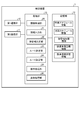
- FIG. 2 is a diagram showing an example of the configuration of the control device according to the first embodiment.
- the control device 7 includes a first communication unit 10, a second communication unit 11, a storage unit 12, and a processing unit 13.
- the first communication unit 10 is connected to each of the interlocking device 6 and the monitoring terminal 91 by a network such as LAN (Local Area Network) or WAN (Wide Area Network) or a dedicated line so as to be able to communicate with each other by wire or wirelessly.
- the second communication unit 11 is wirelessly connected to each vehicle mobile device 8 via a wireless telephone communication network, a wide area data communication network, or the like.
- the second communication unit 11 may be wirelessly connected to each vehicle mobile device 8 via a wireless LAN.
- the storage unit 12 stores work schedule information, patrol schedule information, mobile device status information, railroad vehicle image information, railroad vehicle status information, and the like.
- the work schedule information includes information on the schedule of replacement work of each railroad vehicle 1.
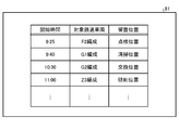
- FIG. 3 is a diagram showing an example of work schedule information according to the first embodiment.
- the work schedule information shown in FIG. 3 includes each information of "work ID (IDentifier)", “start time”, “target railroad vehicle”, “tow start position”, and “tow end position” for each replacement work.
- the "work ID” is identification information unique to the replacement work.
- the “start time” is information indicating the start time of the replacement work.
- the “target railroad vehicle” is information on the railroad vehicle 1 that is the target of the replacement work, and includes, for example, information such as the organization name of the railroad vehicle 1 or the railroad vehicle number of the railroad vehicle 1.
- the "towing start position” is information indicating the position where the vehicle moving machine 8 starts towing the railway vehicle 1. For example, when the railroad vehicle 1 on the main line is towed by the vehicle moving machine 8 to the detention position, the “towing start position” is the position of the boundary region between the end of the main line where the railroad vehicle 1 stops and the entrance / exit of the depot 2. It is information indicating the boundary position which is.
- the "towing end position” is information indicating the position where the vehicle moving machine 8 ends the towing of the railway vehicle 1. For example, when the railroad vehicle 1 on the main line is towed by the vehicle moving machine 8 to the detention position, the “towing end position” is the position of the vehicle moving machine 8 when the railroad vehicle 1 is towed to the detention position.
- the indwelling position is, for example, an inspection position, a cleaning position, a replacement position, a grinding position, or the like.
- the inspection position is a detention position for performing inspection.
- the cleaning position has a detention position for cleaning, and a washer or a washer is arranged.
- the replacement position is a detention position for replacing parts constituting the railway vehicle 1.
- the patrol schedule information stored in the storage unit 12 is information on the patrol schedule in the depot 2 of each vehicle mobile device 8, and includes, for example, information on the travel route and travel time of each vehicle mobile device 8.
- the travel time of each vehicle moving machine 8 included in the patrol schedule information is set to, for example, a time zone in which the replacement work is not performed.
- the mobile device status information includes status information which is information indicating the status of each vehicle mobile device 8.
- the railroad vehicle image information includes information on the captured image of each railroad vehicle 1 and is used for inspection.
- the railroad vehicle image information includes image information obtained by imaging each railroad vehicle 1 in a normal state.
- the railroad vehicle state information includes state information which is information indicating the state of each railroad car 1.
- the state information of the railroad vehicle 1 is information indicating the state of the railroad vehicle 1 detected by the vehicle moving machine 8.
- the processing unit 13 includes an information acquisition unit 20, an information output unit 21, a mobile device determination unit 22, a route determination unit 23, a route setting unit 24, a command processing unit 25, and an inspection processing unit 26.
- the information acquisition unit 20 acquires the state information transmitted wirelessly from each vehicle mobile device 8 and received by the second communication unit 11 from the first communication unit 10.
- the information acquisition unit 20 stores the acquired state information of each vehicle moving machine 8 in the storage unit 12.
- the state information of each vehicle moving machine 8 includes information indicating the current position of the vehicle moving machine 8, information indicating whether or not the vehicle moving machine 8 is working, information indicating the moving distance of the vehicle moving machine 8, and a vehicle. Information such as information indicating the operating time of the mobile device 8, information indicating the remaining capacity of the vehicle mobile device 8, and information indicating the state of each on-board device arranged in the vehicle mobile device 8 is included.
- the state in which the vehicle moving machine 8 is not working may be described as an empty state.
- the moving distance of the vehicle moving machine 8 is the distance moved by the vehicle moving machine 8, for example, the total moving distance or the moving distance in a unit period.
- the operating time of the vehicle moving machine 8 is the time when the vehicle moving machine 8 performs the replacement work. For example, the vehicle moving machine 8 performs the replacement work during the total time or the unit period during which the vehicle moving machine 8 performs the replacement work. It's time.
- the unit period is, for example, one day, one week, or one month.
- the remaining capacity of the vehicle moving machine 8 is the remaining battery capacity when the vehicle moving machine 8 is operated by the battery, and is the remaining fuel when the vehicle moving machine 8 is operated by the fuel.
- the state of each on-vehicle device arranged in the vehicle moving device 8 is, for example, information indicating whether or not each on-vehicle device is operating, or information indicating whether it is normal or abnormal.
- the status information of each vehicle moving machine 8 includes information indicating the progress of the replacement work performed by the vehicle moving machine 8 when the vehicle moving machine 8 is working.
- the progress of the replacement work includes, for example, the progress of the replacement work.
- the information acquisition unit 20 acquires the state information of each railroad vehicle 1 transmitted wirelessly from each vehicle moving machine 8 and received by the second communication unit 11 from the second communication unit 11.
- the information acquisition unit 20 stores the acquired state information of each railroad vehicle 1 in the storage unit 12.
- the state information of the railroad vehicle 1 is information indicating the state of the railroad vehicle 1 detected by the vehicle moving machine 8, and includes, for example, information of a captured image of the railroad vehicle 1.
- the information output unit 21 generates a monitoring image according to a request transmitted from the monitoring terminal 91 and received by the first communication unit 10 by an operation by an operator.
- the information output unit 21 causes the monitoring terminal 91 to transmit the information of the generated monitoring image to the first communication unit 10.
- the information output unit 21 generates a monitoring image including an image showing the position of each rail car 1 and each vehicle moving machine 8 in the depot 2 based on the information stored in the storage unit 12.
- the information of the generated monitoring image is transmitted to the monitoring terminal 91 to the first communication unit 10.
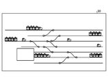
- FIG. 4 is a diagram showing an example of a monitoring image displayed on a monitoring terminal in the central monitoring room according to the first embodiment.
- the surveillance image 80 shown in FIG. 4 is an image in which an image of each railroad vehicle 1 and an image of each vehicle moving machine 8 are superimposed on the layout image of the depot 2.
- the operator of the central monitoring room 9 can easily grasp each state of each railroad vehicle 1 and each vehicle moving machine 8 from the monitoring image 80 shown in FIG. Even if the monitoring image 80 includes identification information of each railroad vehicle 1, identification information of each vehicle moving machine 8, information indicating whether or not each vehicle moving machine 8 is in the process of replacement, and the like are included. good.
- the information output unit 21 shown in FIG. 2 generates a work schedule management image according to a request transmitted from the monitoring terminal 91 and received by the first communication unit 10 by an operation by the operator.
- the information output unit 21 causes the monitoring terminal 91 to transmit the information of the generated work schedule management image to the first communication unit 10.
- FIG. 5 is a diagram showing an example of a work schedule management image displayed on the monitoring terminal of the central monitoring room according to the first embodiment.
- the operator of the central monitoring room 9 can grasp the schedule of the replacement work from the work schedule management image 81 shown in FIG.
- the work schedule management image 81 may include, for example, information indicating the state of each replacement work.
- the information indicating the state of the replacement work is, for example, information indicating whether or not the replacement work has been completed, or information indicating whether or not the replacement work is being executed.
- the operator of the central monitoring room 9 can also change the work schedule, which is the schedule of the replacement work, by operating the monitoring terminal 91.
- the monitoring terminal 91 can transmit the information of the work schedule changed by the operator to the control device 7 as the work schedule information.
- the information acquisition unit 20 of the control device 7 can store the work schedule information transmitted from the monitoring terminal 91 and received by the first communication unit 10 in the storage unit 12. As a result, the work schedule information stored in the storage unit 12 is updated.
- the information output unit 21 shown in FIG. 2 is a monitoring image showing the state of each vehicle mobile device 8 as a monitoring image in response to a request transmitted from the monitoring terminal 91 and received by the first communication unit 10 by an operation by an operator. Can be generated.
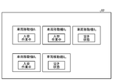
- FIG. 6 is a diagram showing another example of the monitoring image displayed on the monitoring terminal in the central monitoring room according to the first embodiment.
- the monitoring image 82 shown in FIG. 6 includes images showing the states of the vehicle moving machines 8 1 , 8 2 , 8 3 , 8 4 , and 8 m , respectively.
- the monitoring image 82 includes information indicating whether or not the replacement work is being performed as an image showing the state of each vehicle moving machine 8.
- the monitoring image 82 includes, as an image showing the state of the vehicle moving machine 8, information showing the state of the vehicle moving machine 8 in detail in addition to or instead of the information indicating whether or not the replacement work is being performed. May be.
- the information indicating the state of the vehicle moving machine 8 in detail includes, for example, information indicating the current position of the vehicle moving machine 8, information indicating the moving distance of the vehicle moving machine 8, information indicating the operating time of the vehicle moving machine 8, and vehicle movement. At least one of the information indicating the remaining capacity of the machine 8 and the information indicating the state of each on-board device of the vehicle moving machine 8.
- the information output unit 21 generates a monitoring image including information showing in detail the state of the vehicle moving machine 8 selected from the monitoring images 82 shown in FIG. 6, in place of the monitoring image 82, and the generated monitoring image. It is also possible to have the monitoring terminal 91 transmit the information to the first communication unit 10.
- FIG. 7 is a diagram showing still another example of the monitoring image displayed on the monitoring terminal in the central monitoring room according to the first embodiment.
- the monitoring image 83 shown in FIG. 7 is captured by the image sensors of the vehicle moving machines 8 1 , 8 2 , 8 3 selected from the vehicle moving machines 8 1 , 8 2 , 8 3 , 8 4 , and 8 m. The image of the front is included.
- the information output unit 21 shown in FIG. 2 generates a monitoring image including an image of an intruder or an intruder detected by the vehicle moving machine 8 patrolling the vehicle base 2, and the generated monitoring. It is also possible to have the monitoring terminal 91 transmit the image information to the first communication unit 10.
- the information output unit 21 can cause the monitoring terminal 91 to transmit the image corresponding to the request transmitted from the monitoring terminal 91 and received by the first communication unit 10 to the first communication unit 10 by the operation by the operator. ..
- the operator of the central monitoring room 9 can easily grasp the state of the vehicle base 2, the state of each railroad vehicle 1, and the state of each vehicle moving machine 8.
- the information output unit 21 transmits the monitoring images 80, 82, 83 and the work schedule management image 81 to the monitoring terminal 91, but generates the monitoring images 80, 82, 83 and the work schedule management image 81. It is also possible to transmit the image generation information for this purpose to the monitoring terminal 91. In this case, the monitoring terminal 91 generates the monitoring images 80, 82, 83 and the work schedule management image 81 based on the image generation information, and displays the generated monitoring images 80, 82, 83 and the work schedule management image 81. ..
- the operator of the central monitoring room 9 can also operate the monitoring terminal 91 to transmit various commands such as a traction command to each vehicle moving device 8 from the monitoring terminal 91 to the control device 7.
- the information acquisition unit 20 acquires the command from the monitoring terminal 91 from the first communication unit 10 and notifies the information output unit 21 of the acquired command. do.
- the information output unit 21 causes the vehicle mobile device 8 to transmit a command from the monitoring terminal 91 to the second communication unit 11.
- the operator can remotely control the vehicle moving device 8 in an emergency, for example.
- the mobile device determination unit 22 shown in FIG. 2 acquires work schedule information and status information of each vehicle mobile device 8 from the storage unit 12.
- the mobile device determination unit 22 determines the vehicle mobile device 8 to perform each replacement work based on the acquired work schedule information and the state information of each vehicle mobile device 8. For example, when there is only one vehicle moving machine 8 in the vacant state, the moving machine determining unit 22 determines the vehicle moving machine 8 in the vacant state as the vehicle moving machine 8 to perform the replacement work.
- the mobile device determining unit 22 selects the vehicle moving machine 8 closest to the towing start position of the replacement work among the plurality of vacant vehicle moving machines 8. , It is determined as the vehicle moving machine 8 to perform the replacement work.
- the mobile device determination unit 22 determines the vehicle mobile device 8 to perform the replacement work of the work ID “O1”.
- the mobile device determination unit 22 causes the vehicle mobile device 8 closest to the boundary position among the plurality of vehicle mobile devices 8 in the vacant state to perform the vehicle movement for replacing the work ID “O1”. Determined as machine 8.
- the mobile device determination unit 22 causes the vehicle movement to perform the replacement work so that the moving distance or operating time of each vehicle moving machine 8 approaches the average value of the moving distance or the average value of the operating time of all the vehicle moving machines 8.
- the machine 8 can also be determined.
- the mobile device determination unit 22 can also determine the vehicle mobile device 8 to be replaced by giving priority to the vehicle mobile device 8 having a large remaining capacity.
- “k1”, “k2”, “k3”, and “k4" are coefficients.
- “X1”, “x2”, “x3”, and “x4” are parameters for calculating the score Sc. Such a parameter can also be called a feature quantity.
- “X1” is the reachable distance which is the distance from the position of the vehicle moving machine 8 for which the score Sc is calculated to the towing start position of the replacement work.
- “X2” is the moving distance of the vehicle moving machine 8 for which the score Sc is calculated.
- “X3” is the operating time of the vehicle moving machine 8 for which the score Sc is calculated.
- “X4” is the reciprocal of the remaining capacity of the vehicle moving machine 8 for which the score Sc is calculated. It should be noted that one or two or three of “k1”, “k2”, “k3”, and “k4" may be zero.
- the mobile device determination unit 22 determines the vehicle mobile device 8 having the highest score Sc as the vehicle mobile device 8 for performing the replacement work.
- the mobile device determination unit 22 is, for example, on each vehicle arranged in the vehicle mobile device 8 in addition to the above-mentioned reach distance, travel distance, operating time, and remaining capacity as parameters for calculating the score Sc. It is also possible to determine the vehicle moving machine 8 to be replaced, including the state of the device.
- the mobile device determination unit 22 can determine the vehicle mobile device 8 to be replaced based on the score Sc even when there is no vacant vehicle mobile device 8.
- the mobile machine determination unit 22 performs the replacement work using, for example, a formula added to the above formula (1) as a parameter for calculating the score Sc for the time from the current time to the scheduled completion time of the replacement work.
- the vehicle moving machine 8 to be made can be determined.
- the mobile device determination unit 22 can also link a plurality of vehicle mobile devices 8 to each other to pull one railroad vehicle 1 to a plurality of vehicle mobile devices 8.
- the mobile device determination unit 22 determines the vehicle mobile device 8 as the vehicle mobile device 8 to perform the replacement work by the same method as the above-mentioned method. For example, when two vehicle moving machines 8 are assigned to one railroad vehicle 1, the moving machine determination unit 22 has a vehicle moving machine 8 having the lowest score Sc and a vehicle moving machine 8 having the second lowest score Sc. Is determined as the vehicle moving machine 8 for performing the replacement work of one railroad vehicle 1.
- the route determination unit 23 acquires work schedule information from the storage unit 12, and stores information on the current position of the vehicle mobile unit 8 determined by the mobile unit determination unit 22 as the vehicle mobile unit 8 for performing the replacement work. Get from.
- the route determination unit 23 determines the movement route of the vehicle moving machine 8 to perform the replacement work based on the acquired work schedule information and the information of the current position of the vehicle moving machine 8.
- the movement route determined by the route determination unit 23 includes a first movement route from the current position of the vehicle moving machine 8 to be replaced and a towing start position, and a second movement route from the towing start position to the towing end position. Includes travel routes.
- the route determination unit 23 determines, as the first movement route, the movement route from the current position of the vehicle moving machine 8 determined by the moving machine determination unit 22 to the boundary position. Further, the route determination unit 23 determines a movement route from the boundary position to the inspection position as the second movement route.
- the route setting unit 24 generates a switching command based on the movement route determined by the route determining unit 23, and causes the interlocking device 6 to transmit the generated switching command to the first communication unit 10.
- the interlocking device 6 controls one or more turnouts 4 corresponding to the switching command based on the switching command from the route setting unit 24. As a result, the movement route determined by the route determination unit 23 at the depot 2 is set.
- the route setting unit 24 generates a switching command based on the information of the moving route of each vehicle moving machine 8 included in the patrol schedule information in a time zone such as nighttime when the replacement work is not performed, and the generated switching command is generated. Is transmitted to the first communication unit 10 by the interlocking device 6.
- the interlocking device 6 controls one or more turnouts 4 corresponding to the switching command based on the switching command from the route setting unit 24.
- a movement route according to the patrol schedule information at the depot 2 is set.
- the route setting unit 24 can set the second movement route or after the vehicle moving machine 8 can set the first movement route.
- the interlocking device 6 is made to transmit the switching command according to the second movement route to the first communication unit 10.
- the command processing unit 25 causes the second communication unit 11 to transmit a traction command to the vehicle moving machine 8 determined as the vehicle moving machine 8 to be replaced by the moving machine determining unit 22.
- the tow command includes information such as, for example, a tow start position, a tow end position, and a movement route determined by the route determination unit 23. Further, the towing command also includes information on the standby position of the vehicle moving machine 8 after the replacement work is performed.
- the vehicle moving machine 8 moves to the towing start position specified by the towing command based on the towing command transmitted from the control device 7, connects with the railroad vehicle 1, and railroads from the towing start position to the towing end position. Tow vehicle 1.
- the command processing unit 25 decides to have the plurality of vehicle moving machines 8 perform the replacement work of one railroad vehicle 1 by the moving machine determination unit 22, the command processing unit 25 is towed to each of the plurality of vehicle moving machines 8. The command is transmitted to the second communication unit 11.
- the command processing unit 25 moves the vehicle moving machine 8 other than the vehicle moving machine 8 to which the towing command is transmitted among the plurality of vehicle moving machines 8 to the moving route of the vehicle moving machine 8 to perform the replacement work.
- a no-entry command for prohibiting entry is transmitted to the second communication unit 11.
- the depot replacement system 100 can prevent a vehicle moving machine 8 other than the vehicle moving machine 8 for performing the replacement work from entering the moving route of the vehicle moving machine 8 for performing the replacement work.
- the command processing unit 25 gives a patrol command to each vehicle mobile device 8 based on the travel route and travel time information of each vehicle mobile device 8 included in the patrol schedule information during a time zone such as nighttime when replacement work is not performed. Is transmitted to the second communication unit 11.
- the vehicle moving machine 8 performs patrol work at the depot 2 based on the patrol command transmitted from the control device 7.
- the patrol work is a patrol work for detecting the intrusion of the detection target into the depot 2, and the vehicle moving machine 8 patrols the inside of the depot 2 while executing a process of detecting the presence / absence of the detection target. ..
- the vehicle moving device 8 wirelessly transmits the detection result of the detection target to the control device 7.
- the inspection processing unit 26 can inspect the railroad vehicle 1 based on the railroad vehicle state information of the railroad vehicle 1 transmitted from the vehicle moving machine 8. For example, the inspection processing unit 26 scratches the railroad vehicle 1 based on the comparison result between the railroad vehicle image information stored in the storage unit 12 and the information of the captured image of the railroad vehicle 1 transmitted from the vehicle moving machine 8. Alternatively, abnormalities such as deformation can be detected. Further, the inspection processing unit 26 causes the vehicle moving machine 8 to transmit the railway vehicle image information stored in the storage unit 12 to the second communication unit 11 in order to cause the vehicle moving machine 8 to inspect the railway vehicle 1. Can be done.
- FIG. 8 is a diagram showing an example of the configuration of the vehicle moving machine according to the first embodiment.
- the vehicle mobile device 8 includes a wireless communication unit 30, a plurality of sensors 31 1 to 31 k , a coupler 32, a first drive unit 33, a second drive unit 34, and a storage unit. 35 and a processing unit 36 are provided.
- k is an integer of 2 or more.
- the wireless communication unit 30 transmits and receives information by wireless communication to and from the control device 7 via a wireless base station of a wireless telephone communication network or a wireless base station of a wide area data communication network.
- Each sensor 31 1 to 31 k is, for example, a position sensor that calculates the current position of the vehicle moving machine 8, an obstacle sensor that detects an obstacle around the vehicle moving machine 8, and an image that captures the surroundings of the vehicle moving machine 8.
- a sensor a speed sensor that detects the moving speed of the vehicle moving device 8, a sensor that detects an RFID (Radio Frequency IDentification) or a QR (Quick Response) code (registered trademark), and the like.
- one of the plurality of sensors 31 1 to 31 k may be a sensor that detects a barcode instead of a sensor that detects a two-dimensional code such as a QR code.
- the position sensor receives a positioning signal from a positioning satellite such as a GPS (Global Positioning System) satellite, and calculates the current position of the vehicle moving device 8 based on the received positioning signal.
- a positioning satellite such as a GPS (Global Positioning System) satellite
- the coupler 32 is a coupler that is coupled to the coupler of the railway vehicle 1.
- the vehicle moving machine 8 can connect the coupler 32 to the coupler of the railroad vehicle 1 by approaching the railroad vehicle 1 and pressing the coupler 32 against the coupler of the railroad vehicle 1.
- the first drive unit 33 includes a plurality of wheels rotating on the rail 3 and a drive source for rotating at least a part of the plurality of wheels.
- the second drive unit 34 includes a plurality of tires, a drive source for rotating at least a part of the plurality of tires, and a moving mechanism.
- each drive source of the first drive unit 33 and the second drive unit 34 is a motor
- the first drive unit 33 and Each drive source of the second drive unit 34 is an engine.
- the moving mechanism of the second drive unit 34 separates a plurality of wheels from the rail 3 and moves the vehicle moving machine 8 laterally.
- the vehicle moving machine 8 can travel in the area outside the rail 3 with a plurality of tires.
- the lateral direction is a direction orthogonal to the extending direction of the rail 3.
- the moving mechanism of the second drive unit 34 separates a plurality of tires from the area outside the rail 3 and moves the vehicle moving machine 8 laterally to the rail.
- a plurality of wheels can be arranged on the three.
- the storage unit 35 stores command information, mobile device status information, railroad vehicle status information, railroad vehicle image information, and the like.
- the command information includes information on a traction command transmitted from the control device 7, information on a patrol command, information on an entry prohibition command, and the like.
- the mobile device state information is the state information of the vehicle mobile device 8 described above, and is detected by a part of a plurality of sensors 31.
- the railroad vehicle state information is the state information of the railroad vehicle 1 described above, and is detected by a part of a plurality of sensors 31.
- the railroad vehicle image information is image information obtained by imaging the railroad vehicle 1 in a normal state.
- the processing unit 36 includes an information acquisition unit 40, an information output unit 41, a movement control unit 42, a connection control unit 43, a target detection unit 44, and an inspection processing unit 45.
- the information acquisition unit 40 acquires information from the control device 7 received by the wireless communication unit 30, and stores the acquired information in the storage unit 35. Further, the information acquisition unit 40 acquires mobile device state information and railroad vehicle state information from a plurality of sensors 31, and stores the acquired motive state information and railroad vehicle state information in the storage unit 35.
- the information output unit 41 causes the control device 7 to transmit the mobile device state information and the railroad vehicle state information stored in the storage unit 35 to the wireless communication unit 30.
- the movement control unit 42 operates the first drive unit 33 and moves the vehicle moving machine 8 based on the command information acquired by the information acquisition unit 40. For example, when the command information acquired by the information acquisition unit 40 is the information of the traction command, the movement control unit 42 controls the first drive unit 33 to traction from the current position to the traction start position specified by the traction command. The vehicle moving machine 8 is moved by the first movement route specified by the command, and the coupler of the railroad vehicle 1 is connected to the coupler 32 of the vehicle moving machine 8 at the towing start position. After that, the movement control unit 42 controls the first drive unit 33 to move the vehicle moving machine 8 from the towing start position to the towing end position designated by the towing command on the second movement route designated by the towing command. ..
- RFID or QR code is arranged at each towing start position and each towing end position in the depot 2.
- the movement control unit 42 detects that the vehicle moving machine 8 has reached the towing start position or the vicinity of the towing start position when the RFID or QR code corresponding to the towing start position is detected by the sensor 31. Further, the movement control unit 42 detects that the vehicle moving machine 8 has reached the towing end position or the vicinity of the towing end position when the RFID or QR code corresponding to the towing end position is detected by the sensor 31. Further, instead of detecting the RFID or the QR code, the movement control unit 42 causes the vehicle moving machine 8 to pull the tow start position, the tow end position, and the tow start based on the position detected by the position sensor among the plurality of sensors 31. It can also detect that it has reached near the position or near the end of towing position.
- the RFID or QR code may be placed near the towing start position or near the towing end position.
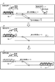
- FIG. 9 is a diagram showing an example of a procedure for towing a railroad vehicle by the vehicle moving machine according to the first embodiment.
- the control device 7 when determining the vehicle movement device 8 2 as the vehicle mobile 8 for pulling the rail vehicle 1 3, the traction command to vehicle movement device 8 2 Send.
- Such a tow command includes information on each of a tow start position, a tow end position, a first movement route, a second movement route, and a standby position.
- the vehicle moving machine 8 2 Upon receiving the traction command from the control device 7, the vehicle moving machine 8 2 receives the traction command, and as shown in the frame B of FIG. 9, the vehicle moving machine 8 2 is designated by the traction command from the current position to the traction start position specified by the traction command. Move the movement route of.
- the traction start position is arranged QR code 50, a vehicle mobile station 82, when detecting the QR code 50, after stopping once, approaches railway vehicle 1 3, coupler 32 railcars 1 By pressing against the coupler of 3, it is connected to the railroad vehicle 13.
- the vehicle mobile station 82 may be connected to the railway vehicle 1 3 towing starting position.
- the vehicle moving machine 8 2 moves from the towing start position to the towing end position specified by the towing command on the second movement route specified by the towing command. ..
- the traction end position is arranged QR code 51, a vehicle mobile station 82 stops moving when it detects the QR code 51, to release the connection between the rail vehicle 1 3. Then, the vehicle moving machine 8 2 moves to the standby position.
- the replacement work of the railroad vehicle 1 can be performed by a plurality of vehicle moving machines 8 in cooperation with each other.
- the control device 7 transmits a towing command to each of the plurality of vehicle moving devices 8.
- Each vehicle moving machine 8 pulls the railway vehicle 1 in cooperation with each other based on the towing command transmitted from the control device 7.
- FIG. 10 is a diagram showing another example of the procedure for towing a railroad vehicle by the vehicle moving machine according to the first embodiment.
- the control device 7 when determining the vehicle movement device 8 2, 8 3 as vehicle mobile pulling the railway vehicle 1 3, the vehicle mobile station 8 2, 8 3 A tow command is sent to it.
- the towing command for each of the vehicle moving machines 8 2 and 8 3 includes information on the towing start position, the towing end position, the movement route, and the standby position.
- towing command to the vehicle mobile station 82 pulling the start position is the current position
- travel route is a second travel route shown in the A frame of FIG. 10.
- moving route is a first route of travel and the second travel route shown in the A frame of FIG. 10.
- the vehicle moving machine 8 3 Upon receiving the traction command from the control device 7, the vehicle moving machine 8 3 receives the traction command, and as shown in the frame B of FIG. 10, the vehicle moving machine 8 3 is designated by the traction command from the current position to the traction start position specified by the traction command. Move the movement route of.
- the traction start position is arranged QR code 53, a vehicle mobile station 8 3, when detecting the QR code 53, after stopping once, approaches railway vehicle 1 3, coupler 32 railcars 1 By pressing against the coupler of 3, it is connected to the railroad vehicle 13.
- the vehicle mobile station 8 3 can be connected to the railway vehicle 1 3 towing starting position.
- the vehicle moving machines 8 2 and 8 3 move on the second movement route specified by the traction command to the traction end position specified by the traction command as shown in the C frame of FIG.
- the traction end position, QR code (not shown) has been arranged, the vehicle mobile station 8 2, 8 3, stops moving when it detects a QR code (not shown), the connection between the railway vehicle 1 3 unlock. Then, the vehicle moving machines 8 2 and 8 3 move to the standby position.
- the one or more vehicle moving machines 8 can tow the railroad vehicle 1 based on the towing command.
- the position detection by the vehicle moving device 8 in FIGS. 9 and 10 is not limited to the detection of the QR code, and may be the detection of RFID or the position detection based on the positioning signal from the positioning satellite. ..
- the railway vehicle 1 to be towed may not exist due to an operation delay or the like.
- the information output unit 41 of the vehicle moving device 8 determines that the railroad vehicle 1 to be towed does not exist, the information output unit 41 causes the control device 7 to transmit information indicating that the railroad vehicle 1 to be towed does not exist to the wireless communication unit 30. ..
- the processing unit 13 of the control device 7 can change the work schedule information based on the information indicating that the railroad vehicle 1 to be towed does not exist.
- the information output unit 41 can determine whether or not the railroad vehicle 1 to be towed exists based on the image captured by the sensor 31 at the towing start position.
- the processing unit 13 of the control device 7 transmits information indicating that the railroad vehicle 1 to be towed does not exist from the vehicle moving machine 8, the processing unit 13 relates to the railroad vehicle operation management system that manages the operation of the railroad vehicle 1. Inquire about the operation status of railroad vehicle 1.
- the processing unit 13 of the control device 7 can change the work schedule information based on the operation status of the railway vehicle 1 notified from the railway vehicle operation management system.
- the processing unit 13 of the control device 7 periodically inquires of the railway vehicle operation management system about the operation status of each railway vehicle 1, and the operation of the railway vehicle 1 is periodically notified by the railway vehicle operation management system. Work schedule information can also be changed based on the situation.
- the information output unit 41 determines, for example, whether or not the railroad vehicle 1 is the target of towing from the image captured by the sensor 31.
- the towing command includes towing target information, which is information on the towing target railroad vehicle 1, and by comparing the towing target information with the information obtained from the image captured by the sensor 31, the towing target railroad. It is determined whether or not the vehicle is 1.
- the information output unit 41 sends information to the control device 7 that the railroad vehicle 1 different from the railroad vehicle 1 to be towed exists. It is transmitted to the wireless communication unit 30.
- the processing unit 13 of the control device 7 can change the work schedule information based on the information indicating that the railroad vehicle 1 different from the railroad vehicle 1 to be towed exists. As described above, the change of the work schedule information by the processing unit 13 of the control device 7 is performed based on the operation status of the railway vehicle 1 obtained from the railway vehicle operation management system that manages the operation of the railway vehicle 1.
- an image sensor that images the front of the vehicle moving machine 8 and an image sensor that images the rear of the vehicle moving machine 8 are arranged as sensors 31, respectively.
- the movement control unit 42 determines that the distance to the other vehicle moving machine 8 is less than the preset distance based on the front image and the rear image of the vehicle moving machine 8 output from these sensors 31. do.
- the movement control unit 42 determines that the distance between the arranged vehicle moving machine 8 and the other vehicle moving machine 8 is less than the preset distance, the moving vehicle moving machine 8 and the other vehicle moving machine 8 are arranged.
- the first drive unit 33 is operated so as not to collide with 8. As a result, it is possible to avoid a collision between the vehicle moving devices 8.
- the movement control unit 42 operates the first drive unit 33 so as to avoid collision between the vehicle mobile devices 8 by transmitting and receiving information to and from the other vehicle mobile devices 8 via the wireless communication unit 30. You can also do it.
- the movement control unit 42 acquires information on the current position of the other vehicle moving machine 8 via the wireless communication unit 30, and the current position of the vehicle moving machine 8 to be arranged and the current position of the other vehicle moving machine 8. Based on the above, the first drive unit 33 can be operated so as to avoid a collision between the vehicle moving devices 8.
- the coupling control unit 43 shown in FIG. 8 drives the coupler 32 after the vehicle moving machine 8 has moved to the towing end position, and disconnects the coupler 32 of the vehicle moving machine 8 from the coupler of the railway vehicle 1.
- the movement control unit 42 operates at least one of the first drive unit 33 and the second drive unit 34 to move the vehicle moving machine 8. ..
- the destination of the vehicle moving machine 8 is, for example, a predetermined position or a standby position designated by a towing command.
- the movement control unit 42 moves the patrol route specified by the patrol command to the vehicle moving machine 8. Further, the movement control unit 42 is designated by the entry prohibition command when the information of the entry prohibition command is acquired by the information acquisition unit 40 while the vehicle moving machine 8 is being moved based on the towing command or the patrol command. Do not allow the vehicle moving machine 8 to enter the moving route.
- the target detection unit 44 detects the intrusion of the detection target into the vehicle base 2, for example, based on the image captured by the image sensor which is the sensor 31. do.
- the detection target is an animal invading the depot 2, and the animal includes a human being.
- the detection target is an intruder into the depot 2 or an animal such as a raccoon dog or a fox invading the depot 2.
- the target detection unit 44 can also detect the intrusion of the detection target into the depot 2 based on the detection result by the infrared sensor or the radar, which is the sensor 31, for example. Further, the target detection unit 44 can also detect the intrusion of the detection target into the depot 2 based on the detection results of the plurality of sensors 31. For example, the target detection unit 44 can detect the intrusion of the detection target into the depot 2 based on the image captured by the image sensor and the detection result by the infrared sensor.
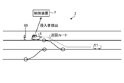
- FIG. 11 is a diagram showing a state of detection of an intruder by patrol of the vehicle moving machine according to the first embodiment.
- the vehicle moving machine 8 detects an intruder 60 while traveling on the patrol route designated by the control device 7, the detection result indicating that the intruder 60 has been detected is transmitted to the control device 7.
- the control device 7 notifies the central monitoring room 9 of the detection result of the intruder 60 by the vehicle moving device 8.
- the operator of the central monitoring room 9 can grasp the intruder 60 who has entered the depot 2.
- the vehicle moving device 8 can also include the image of the intruder 60 in the detection result of the intruder 60 by the sensor 31 and transmit it to the control device 7.
- the inspection processing unit 45 shown in FIG. 8 can inspect the railway vehicle 1 based on the railway vehicle state information stored in the storage unit 35.
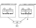
- the inspection processing unit 45 is, for example, based on a comparison result between the image shown by the railway vehicle image information stored in the storage unit 35 and the image of the railway vehicle 1 captured by the sensor 31 which is an image sensor. Abnormalities such as scratches or deformations of 1 can be detected.
- FIG. 12 is a diagram for explaining an example of the inspection method by the vehicle moving machine according to the first embodiment.
- the inspection processing unit 45 compares the image shown by the railway vehicle image information with the image of the railway vehicle 1 captured by the sensor 31 which is an image sensor. Since the railroad vehicle 1 imaged by the sensor 31 has scratches that the railroad car 1 in the normal state does not have, the inspection processing unit 45 detects that the railroad car 1 to be inspected has scratches.
- the movement control unit 42 shown in FIG. 8 determines that the drive source of the vehicle moving device 8 is a battery and the remaining battery level detected by the sensor 31 is equal to or less than the threshold value, the movement control unit 42 moves to the charging stand and charges the vehicle. You can also charge the battery from the stand.
- FIG. 13 is a flowchart showing an example of processing by the processing unit of the control device according to the first embodiment.
- the processing unit 13 of the control device 7 repeatedly executes the processing shown in FIG.
- the processing unit 13 of the control device 7 determines whether or not the replacement work instruction timing has been reached based on the work schedule information stored in the storage unit 12 (step S10).
- the processing unit 13 performs the replacement work based on the work schedule information stored in the storage unit 12 and the state information of each vehicle moving machine 8.
- the vehicle moving machine 8 to be to be moved is determined (step S11).
- the processing unit 13 causes the vehicle moving machine 8 to perform the replacement work based on the work schedule information stored in the storage unit 12 and the information on the current position of the vehicle moving machine 8 determined in the process of step S11.
- the travel route is determined (step S12).
- the processing unit 13 sets the movement route of the vehicle moving machine 8 determined in the processing of step S12 (step S13).
- the processing unit 13 generates a switching command based on the movement route determined in the process of step S12, and causes the interlocking device 6 to transmit the generated switching command to the first communication unit 10.
- the turnout 4 is controlled by the interlocking device 6, and the movement route of the vehicle moving machine 8 is set at the vehicle base 2.
- the processing unit 13 causes the vehicle moving machine 8 determined in the process of step S12 to transmit the traction command to the second communication unit 11 (step S14).
- a tow command includes, for example, information on a tow start position, a tow end position, a movement route, and a standby position.
- step S14 When the processing unit 13 has completed the processing in step S14, or when it is determined that the timing for instructing the replacement work has not arrived (step S10: No), the information from the vehicle moving machine 8 is received by the second communication unit 11. It is determined whether or not it has been done (step S15). When the processing unit 13 determines that the information from the vehicle moving machine 8 has been received (step S15: Yes), the processing unit 13 acquires the information from the vehicle moving machine 8 received by the second communication unit 11, and the acquired information. Is stored in the storage unit 12 (step S16).
- the request from the monitoring terminal 91 is the first communication unit 10. It is determined whether or not it was received in (step S17).
- the processing unit 13 determines that the request from the monitoring terminal 91 has been received by the first communication unit 10 (step S17: Yes)
- the processing unit 13 acquires the request from the monitoring terminal 91 from the first communication unit 10 and the monitoring terminal 91. Information corresponding to the request from is generated, and the generated information is transmitted to the monitoring terminal 91 to the first communication unit 10 (step S18).
- step S18 When the processing of step S18 is completed, or when it is determined that the request from the monitoring terminal 91 has not been received by the first communication unit 10 (step S17: No), the processing unit 13 ends the processing shown in FIG. do.
- FIG. 14 is a flowchart showing an example of processing by the processing unit of the vehicle moving machine according to the first embodiment.
- the processing unit 36 of the vehicle moving machine 8 repeatedly executes the processing shown in FIG.
- the processing unit 36 of the vehicle moving device 8 determines whether or not the traction command has been received by the wireless communication unit 30 (step S20).
- the processing unit 36 determines that the traction command has been received by the wireless communication unit 30 (step S20: Yes)
- the processing unit 36 performs traction processing (step S21).
- the traction process is the process of steps S30 to S34 shown in FIG. 15, which will be described in detail later.
- step S21 When the processing of step S21 is completed or when it is determined that the traction command has not been received (step S20: No), the processing unit 36 determines whether or not the patrol command has been received by the wireless communication unit 30 (step S20: No). Step S22). When it is determined that the patrol command has been received (step S22: Yes), the processing unit 36 performs patrol processing (step S23).
- the patrol process is the process of steps S40 to S43 shown in FIG. 16, which will be described in detail later.
- the processing unit 36 ends the processing shown in FIG. 14 when the processing in step S23 is completed or when it is determined that the patrol command has not been received by the wireless communication unit 30 (step S22: No).
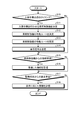
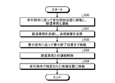
- FIG. 15 is a flowchart showing an example of the traction process by the processing unit of the vehicle moving machine according to the first embodiment.
- the processing unit 36 operates the first drive unit 33 according to the traction command received from the control device 7 by the wireless communication unit 30, moves the vehicle moving machine 8 to the traction start position, and starts traction.
- the vehicle moving machine 8 is connected to the railroad vehicle 1 (step S30).
- the processing unit 36 inspects the railroad vehicle 1 based on the detection result by the sensor 31 that detects the state of the railroad vehicle 1, and causes the control device 7 to transmit the inspected result to the wireless communication unit 30 (step S31). ).
- the processing unit 36 inspects the railway vehicle 1 based on, for example, the image of the railway vehicle 1 captured by the sensor 31, and causes the control device 7 to transmit the inspection result to the wireless communication unit 30. ..
- the processing unit 36 can inspect the vehicle moving machine 8 at a position other than the towing start position in place of or in addition to inspecting the vehicle moving machine 8 at the towing start position.
- the processing unit 36 can inspect the railroad vehicle 1 based on the detection result by the sensor 31 that detects the state of the railroad vehicle 1 while approaching the vehicle moving machine 8. Further, the processing unit 36 can also inspect the vehicle moving machine 8 different from the towing target while moving for the replacement work.
- the processing unit 36 operates the first drive unit 33 in accordance with the traction command to move the vehicle moving machine 8 to the traction end position (step S32). Then, the processing unit 36 controls the coupler 32 to release the connection between the vehicle moving machine 8 and the railroad vehicle 1 (step S33). After breaking the connection between the processing unit 36 and the railway vehicle 1, at least one of the first drive unit 33 and the second drive unit 34 is operated to move the vehicle moving machine 8 to the standby position designated by the traction command. It is moved (step S34), and the process shown in FIG. 15 is terminated.
- FIG. 16 is a flowchart showing an example of patrol processing by the processing unit of the vehicle moving machine according to the first embodiment.
- the processing unit 36 operates the first drive unit 33 according to the patrol command received by the wireless communication unit 30 from the control device 7 to start patrol of the vehicle moving machine 8 (step S40).
- the processing unit 36 determines whether or not the detection target has been detected based on the information acquired from the sensor 31 (step S41). When the processing unit 36 determines that the detection target has been detected (step S41: Yes), the processing unit 36 causes the control device 7 to transmit the detection result indicating that the detection target has been detected to the wireless communication unit 30 (step S42). The processing unit 36 can also cause the control device 7 to transmit the detection result indicating the presence / absence of the detection target to the wireless communication unit 30 regardless of whether or not the detection target is detected.
- step S42 determines whether or not the patrol according to the patrol command is completed (step). S43).
- step S43 determines that the patrol has not been completed (step S43: No)
- step S43 shifts the processing to step S41.
- step S43: Yes the processing unit 36 ends the processing shown in FIG.
- the processing unit 36 can also inspect the vehicle moving machine 8 during the patrol.
- the movement route is determined by the processing unit 13 of the control device 7, but the movement route is the processing of the vehicle moving machine 8 determined as the vehicle moving machine 8 to perform the replacement work by the control device 7.
- the unit 36 can do it.
- the processing unit 36 of the vehicle moving machine 8 can determine the first moving route and the second moving route based on the towing start position and the towing end position included in the towing command.
- the processing unit 36 of the vehicle mobile device 8 can transmit / receive information to / from another vehicle mobile device 8 by wireless communication by the wireless communication unit 30.
- the processing unit 36 of the vehicle moving machine 8 can determine the first moving route and the second moving route based on the information acquired from the other vehicle moving machines 8.
- the information acquired from the other vehicle moving machine 8 is, for example, information on the moving route in the replacement work performed by the other vehicle moving machine 8.
- the processing unit 36 of the vehicle moving machine 8 determines the first moving route and the second moving route, the first moving route and the second moving route to the control device 7 via the wireless communication unit 30. Can be requested.
- the control device 7 can generate a switching command based on the request from the vehicle moving device 8, and cause the interlocking device 6 to transmit the generated switching command to the first communication unit 10.
- the processing unit 36 of the vehicle moving machine 8 may generate a switching command according to the first moving route and the second moving route, and cause the interlocking device 6 to transmit the generated switching command to the wireless communication unit 30. can.
- vehicle base replacement system 100 described above has a configuration having a plurality of vehicle mobile devices 8, the number of vehicle mobile devices 8 may be one. Further, although the vehicle base replacement system 100 described above manages one vehicle base 2, it may be configured to manage a plurality of vehicle bases 2.
- FIG. 17 is a diagram showing an example of each hardware configuration of the processing unit of the control device and the processing unit of the vehicle moving device according to the first embodiment.
- each of the processing units 13 and 36 includes a computer including a processor 101 and a memory 102.
- the processor 101 and the memory 102 can send and receive information to and from each other by, for example, the bus 103.
- the processor 101 executes the function of the processing unit 13 by reading and executing the program stored in the memory 102. Further, the processor 101 executes the function of the processing unit 36 by reading and executing the program stored in the memory 102.
- the processor 101 is, for example, an example of a processing circuit, and includes one or more of a CPU (Central Processing Unit), a DSP (Digital Signal Processor), and a system LSI (Large Scale Integration).
- the memory 102 includes one or more of RAM (Random Access Memory), ROM (Read Only Memory), flash memory, EPROM (Erasable Programmable Read Only Memory), and EEPROM (registered trademark) (Electrically Erasable Programmable Read Only Memory). include. Further, the memory 102 includes a recording medium in which a computer-readable program is recorded. Such recording media include one or more of non-volatile or volatile semiconductor memories, magnetic disks, flexible memories, optical discs, compact disks, and DVDs (Digital Versatile Discs). Each of the processing units 13 and 36 may include integrated circuits such as an ASIC (Application Specific Integrated Circuit) and an FPGA (Field Programmable Gate Array).
- ASIC Application Specific Integrated Circuit
- FPGA Field Programmable Gate Array
- the vehicle base replacement system 100 includes a vehicle moving device 8 and a control device 7.
- the vehicle moving machine 8 pulls the railroad vehicle 1 at the depot 2.
- the control device 7 transmits a towing command to the vehicle moving device 8 based on the work schedule.
- the vehicle moving machine 8 moves to the towing start position specified by the towing command based on the towing command transmitted from the control device 7, connects with the railroad vehicle 1, and is designated by the towing command from the towing start position.
- the railroad vehicle 1 is towed to the towing end position.
- the tow start position is an example of the first position
- the tow end position is an example of the second position.
- the depot replacement system 100 can reduce or eliminate work errors due to human error, and can efficiently perform the replacement work of the railroad vehicle 1 at the depot 2. Further, in the depot replacement system 100, it is not necessary for a qualified person who can drive the rolling stock moving machine to operate the rolling stock moving machine as in the conventional case, and the replacement work of a plurality of railroad cars 1 is monitored by a small number of personnel. Therefore, it is possible to reduce the number of qualified persons at the depot 2.
- control device 7 includes a mobile device determination unit 22.
- the mobile device determination unit 22 determines the vehicle mobile device 8 for transmitting the towing command among the plurality of vehicle mobile devices 8 based on the states of the plurality of vehicle mobile devices 8. Thereby, the vehicle base replacement system 100 can determine an appropriate vehicle moving machine 8 according to the state of the vehicle moving machine 8 as the vehicle moving machine 8 for performing the replacement work.
- control device 7 includes a route determination unit 23.
- the route determination unit 23 determines a first movement route to the towing start position of the vehicle moving machine 8 and a second moving route from the towing start position to the towing end position of the vehicle moving machine 8.
- the depot replacement system 100 can manage the movement route of the vehicle moving machine 8, and can efficiently perform the replacement work of the railroad vehicle 1 at the depot 2.
- control device 7 causes the vehicle moving machine 8 other than the vehicle moving machine 8 to which the towing command is transmitted among the plurality of vehicle moving machines 8 to enter the first moving route and the second moving route. Send a banned entry command.
- the depot replacement system 100 can prevent the replacement work by the vehicle moving machine 8 from being hindered by another vehicle moving machine 8, and efficiently performs the replacement work of the railroad vehicle 1 at the vehicle base 2. be able to.
- the plurality of vehicle moving machines 8 move the railroad vehicle 1 designated by the towing command in cooperation with each other based on the towing command.
- the depot replacement system 100 can efficiently perform the replacement work of the railroad vehicle 1 at the depot 2 even when the railroad vehicle 1 cannot be towed by one vehicle moving machine 8, for example.
- the vehicle mobile device 8 includes a target detection unit 44 that detects the intrusion of the detection target into the depot 2.
- the control device 7 transmits a patrol command to the vehicle mobile device 8 based on a preset patrol schedule.
- the vehicle mobile device 8 is detected by the target detection unit 44 based on the patrol command transmitted from the control device 7.
- the vehicle base 2 is patrolled while detecting the presence or absence of the target.
- the vehicle base replacement system 100 can make the vehicle moving device 8 function as a security equipment, and can simplify the security equipment installed in the vehicle base 2.
- the vehicle moving machine 8 includes one or more sensors 31 for inspecting the railroad vehicle 1 designated by the traction command.
- the control device 7 or the vehicle moving machine 8 inspects the railway vehicle 1 designated by the traction command based on the results detected by one or more sensors 31.
- the depot replacement system 100 can inspect the railroad vehicle 1 in the depot 2.
- the one or more sensors 31 include an image sensor.
- the control device 7 or the vehicle moving machine 8 scratches or deforms the railway vehicle 1 by comparing the image of the railway vehicle 1 specified by the traction command captured by the image sensor with the image of the railway vehicle 1 in the normal state. Detects abnormalities such as. Thereby, the vehicle base replacement system 100 can inspect the railroad vehicle 1 in the vehicle base 2 by using, for example, one or more sensors 31 used for the replacement work.
- the configuration shown in the above embodiment is an example, and can be combined with another known technique, or a part of the configuration may be omitted or changed without departing from the gist. It is possible.
Landscapes
- Engineering & Computer Science (AREA)
- Mechanical Engineering (AREA)
- Train Traffic Observation, Control, And Security (AREA)
- Electric Propulsion And Braking For Vehicles (AREA)
Abstract
Description
図1は、実施の形態1にかかる車両基地入替システムの構成例を示す図である。図1に示すように、実施の形態1にかかる車両基地入替システム100は、車両基地2において、複数の鉄道車両11,12,13,14~1nの入替作業を行う。nは、例えば、5以上の整数である。以下、複数の鉄道車両11,12,13,14~1nの各々を個別に区別せずに示す場合、鉄道車両1と記載する場合がある。なお、図1に示す例では、鉄道車両1は、複数の車両が連結された鉄道車両であるが、1つの車両から構成されてもよい。
Sc=k1×x1+k2×x2+k3×x3+k4×x4 ・・・(1)
Claims (11)
- 車両基地において鉄道車両の牽引を行う車両移動機と、
作業スケジュールに基づいて、前記車両移動機へ牽引指令を送信する制御装置と、を備え、
前記車両移動機は、
前記制御装置から送信される前記牽引指令に基づいて、前記牽引指令で指定される第1の位置まで移動して前記鉄道車両との連結を行い、前記第1の位置から前記牽引指令で指定される第2の位置まで前記鉄道車両を牽引する
ことを特徴とする車両基地入替システム。 - 複数の前記車両移動機を備え、
前記制御装置は、
前記複数の車両移動機の状態に基づいて、前記複数の車両移動機のうち前記牽引指令を送信する前記車両移動機を決定する移動機決定部を備える
ことを特徴とする請求項1に記載の車両基地入替システム。 - 前記制御装置は、
前記車両移動機の前記第1の位置までの第1の移動ルートと、前記車両移動機の前記第1の位置から前記第2の位置までの第2の移動ルートを決定するルート決定部と、
前記ルート決定部によって決定された前記第1の移動ルートと前記第2の移動ルートに基づいて、前記車両基地における転てつ器を連動装置に制御させるルート設定部と、を備える
ことを特徴とする請求項2に記載の車両基地入替システム。 - 前記制御装置は、
前記複数の車両移動機のうち前記牽引指令が送信される車両移動機以外の車両移動機に対して、前記第1の移動ルートおよび前記第2の移動ルートへの進入を禁止する進入禁止指令を送信する
ことを特徴とする請求項3に記載の車両基地入替システム。 - 前記複数の車両移動機は、
前記牽引指令に基づいて、互いに連携して前記牽引指令で指定される鉄道車両を移動させる
ことを特徴とする請求項2から4のいずれか1つに記載の車両基地入替システム。 - 前記車両移動機は、
前記車両基地への検出対象の侵入を検出する対象検出部を備え、
前記制御装置は、
予め設定された巡回スケジュールに基づいて、前記車両移動機へ巡回指令を送信し、
前記車両移動機は、
前記制御装置から送信される前記巡回指令に基づいて、前記対象検出部で前記検出対象の有無を検出しながら前記車両基地を巡回する
ことを特徴とする請求項1から5のいずれか1つに記載の車両基地入替システム。 - 前記車両移動機は、
前記鉄道車両を点検するためのセンサを備え、
前記制御装置または前記車両移動機は、
前記センサで検出された結果に基づいて、前記鉄道車両の点検を行う
ことを特徴とする請求項1から6のいずれか1つに記載の車両基地入替システム。 - 前記センサは、
イメージセンサであり、
前記制御装置または前記車両移動機は、
前記イメージセンサで撮像された前記鉄道車両の画像と正常時の前記鉄道車両の画像とを比較することによって、前記鉄道車両の異状を検出する
ことを特徴とする請求項7に記載の車両基地入替システム。 - 作業スケジュールを取得する取得部と、
車両基地において鉄道車両の牽引を行う車両移動機と通信する通信部と、
前記取得部で取得された前記作業スケジュールに基づいて、前記車両移動機に対し、牽引指令を前記通信部に送信させる制御部と、を備える
ことを特徴とする制御装置。 - コンピュータが実行する制御方法であって、
作業スケジュールを取得する第1のステップと、
前記第1のステップで取得された前記作業スケジュールに基づいて、車両基地において鉄道車両の牽引を行う車両移動機に牽引指令を送信する第2のステップと、を含む
ことを特徴とする制御方法。 - 作業スケジュールを取得する第1のステップと、
前記第1のステップで取得された前記作業スケジュールに基づいて、車両基地において鉄道車両の牽引を行う車両移動機に牽引指令を送信する第2のステップと、をコンピュータに実行させる
ことを特徴とする制御プログラム。
Priority Applications (5)
| Application Number | Priority Date | Filing Date | Title |
|---|---|---|---|
| PCT/JP2020/019035 WO2021229701A1 (ja) | 2020-05-12 | 2020-05-12 | 車両基地入替システム、制御装置、制御方法、および制御プログラム |
| CN202080100309.1A CN115461267A (zh) | 2020-05-12 | 2020-05-12 | 车辆基地调车系统、控制装置、控制方法以及控制程序 |
| JP2020552424A JP6818963B1 (ja) | 2020-05-12 | 2020-05-12 | 車両基地入替システム |
| US17/912,941 US12545305B2 (en) | 2020-05-12 | 2020-05-12 | Rail yard train-switching system, control device, and control method |
| EP20935379.6A EP4151500A4 (en) | 2020-05-12 | 2020-05-12 | Rail yard replacement system, control device, control method, and control program |
Applications Claiming Priority (1)
| Application Number | Priority Date | Filing Date | Title |
|---|---|---|---|
| PCT/JP2020/019035 WO2021229701A1 (ja) | 2020-05-12 | 2020-05-12 | 車両基地入替システム、制御装置、制御方法、および制御プログラム |
Publications (1)
| Publication Number | Publication Date |
|---|---|
| WO2021229701A1 true WO2021229701A1 (ja) | 2021-11-18 |
Family
ID=74200197
Family Applications (1)
| Application Number | Title | Priority Date | Filing Date |
|---|---|---|---|
| PCT/JP2020/019035 Ceased WO2021229701A1 (ja) | 2020-05-12 | 2020-05-12 | 車両基地入替システム、制御装置、制御方法、および制御プログラム |
Country Status (5)
| Country | Link |
|---|---|
| US (1) | US12545305B2 (ja) |
| EP (1) | EP4151500A4 (ja) |
| JP (1) | JP6818963B1 (ja) |
| CN (1) | CN115461267A (ja) |
| WO (1) | WO2021229701A1 (ja) |
Families Citing this family (4)
| Publication number | Priority date | Publication date | Assignee | Title |
|---|---|---|---|---|
| WO2023164180A1 (en) * | 2022-02-24 | 2023-08-31 | Advanced Rail Systems, Llc | Railroad computing system and device |
| KR102942518B1 (ko) * | 2023-07-20 | 2026-03-23 | 한국철도기술연구원 | 철도 차량용 자동 입환 시스템 |
| KR102904880B1 (ko) * | 2023-09-04 | 2025-12-29 | 한국철도기술연구원 | 열차의 가변궤간 선로 운행을 위한 견인 시스템 및 이를 이용한 견인 방법 |
| KR102945294B1 (ko) | 2023-11-02 | 2026-04-09 | 한국철도기술연구원 | 변환궤도 인장력 강화를 위한 랙 피니언 타입 변환궤도 견인 간이대차 |
Citations (3)
| Publication number | Priority date | Publication date | Assignee | Title |
|---|---|---|---|---|
| JP2007001519A (ja) | 2005-06-27 | 2007-01-11 | Hitachi Ltd | 車両基地内の地上情報処理装置、車両遠隔操作支援システム及び方法 |
| JP2013045329A (ja) * | 2011-08-25 | 2013-03-04 | Mitsubishi Heavy Ind Ltd | 軌道系車両管理システムおよび対処決定方法 |
| CN108528477A (zh) * | 2018-04-23 | 2018-09-14 | 西南交通大学 | 一种地铁车辆段/停车场综合自动化系统 |
Family Cites Families (14)
| Publication number | Priority date | Publication date | Assignee | Title |
|---|---|---|---|---|
| JP3296200B2 (ja) | 1996-09-10 | 2002-06-24 | 三菱電機株式会社 | 列車自動入れ替え制御装置 |
| KR19990064774A (ko) | 1999-05-08 | 1999-08-05 | 정종원 | 궤도차량용 차축베어링 이상상태 경보장치 |
| US6446912B1 (en) * | 2000-11-29 | 2002-09-10 | General Electric Company | Railcar maintenance management method |
| CN1284699C (zh) | 2004-03-02 | 2006-11-15 | 北京全路通信信号研究设计院 | 编组站调车机车自动化系统 |
| CN100372720C (zh) * | 2006-03-24 | 2008-03-05 | 北京全路通信信号研究设计院 | 用于编制铁路调车计划的装置和方法 |
| CN101121411A (zh) | 2006-08-07 | 2008-02-13 | 王春花 | 铁路轨道检视车及其在铁路安全行车中的应用 |
| JP6029743B2 (ja) | 2013-03-29 | 2016-11-24 | 三菱重工業株式会社 | 車上装置、信号システム及び移動装置の制御方法 |
| US10894552B2 (en) * | 2014-03-27 | 2021-01-19 | Transportation Ip Holdings, Llc | System and method integrating an energy management system and yard planner system |
| US9878724B2 (en) * | 2015-08-12 | 2018-01-30 | Trackmobile Llc | Traction assist for railcar mover |
| CN105243381B (zh) | 2015-11-25 | 2019-04-19 | 朱金良 | 基于3d信息的故障自动识别检测系统及方法 |
| US10814889B2 (en) * | 2017-10-09 | 2020-10-27 | Trackmobile Llc | Modular drive train for railcar mover |
| CN108639108B (zh) | 2018-05-12 | 2021-02-09 | 西北铁道电子股份有限公司 | 一种机车作业安全防护系统 |
| CN108819990A (zh) * | 2018-05-28 | 2018-11-16 | 丁昆 | 铁路调车场集成控制系统 |
| WO2022201042A1 (en) * | 2021-03-23 | 2022-09-29 | Kaci Intermodal Systems, Llc | Freight handling system and method |
-
2020
- 2020-05-12 WO PCT/JP2020/019035 patent/WO2021229701A1/ja not_active Ceased
- 2020-05-12 EP EP20935379.6A patent/EP4151500A4/en active Pending
- 2020-05-12 JP JP2020552424A patent/JP6818963B1/ja active Active
- 2020-05-12 CN CN202080100309.1A patent/CN115461267A/zh active Pending
- 2020-05-12 US US17/912,941 patent/US12545305B2/en active Active
Patent Citations (3)
| Publication number | Priority date | Publication date | Assignee | Title |
|---|---|---|---|---|
| JP2007001519A (ja) | 2005-06-27 | 2007-01-11 | Hitachi Ltd | 車両基地内の地上情報処理装置、車両遠隔操作支援システム及び方法 |
| JP2013045329A (ja) * | 2011-08-25 | 2013-03-04 | Mitsubishi Heavy Ind Ltd | 軌道系車両管理システムおよび対処決定方法 |
| CN108528477A (zh) * | 2018-04-23 | 2018-09-14 | 西南交通大学 | 一种地铁车辆段/停车场综合自动化系统 |
Non-Patent Citations (1)
| Title |
|---|
| See also references of EP4151500A4 |
Also Published As
| Publication number | Publication date |
|---|---|
| EP4151500A4 (en) | 2023-06-28 |
| US12545305B2 (en) | 2026-02-10 |
| JPWO2021229701A1 (ja) | 2021-11-18 |
| US20230202543A1 (en) | 2023-06-29 |
| CN115461267A (zh) | 2022-12-09 |
| JP6818963B1 (ja) | 2021-01-27 |
| EP4151500A1 (en) | 2023-03-22 |
Similar Documents
| Publication | Publication Date | Title |
|---|---|---|
| JP6818963B1 (ja) | 車両基地入替システム | |
| RU2417912C2 (ru) | Система и способ определения, сцеплен ли локомотив или железнодорожная тяговая установка с железнодорожным вагоном или другой тяговой установкой | |
| JP4197209B2 (ja) | 車両の無人走行システム | |
| US20180339703A1 (en) | Vehicle with remote-controlled operating mode | |
| CN102858615B (zh) | 管理与被引导车辆的移动有关的特殊事件的方法和系统 | |
| US8380361B2 (en) | System, method, and computer readable memory medium for remotely controlling the movement of a series of connected vehicles | |
| CN109979218A (zh) | 自主移动体以及信息收集系统 | |
| CN104050729A (zh) | 收集与自主式工业用车辆的操作有关的视频数据的系统和方法 | |
| WO2024055438A1 (zh) | 一种列车自主感知系统 | |
| CN112441075A (zh) | 轨道交通外部环境感知系统、方法和轨道交通设备 | |
| CN115782981B (zh) | 轨道交通无人列控系统故障场景下的远程应急驾驶系统 | |
| CN111033416A (zh) | 对运输车的控制 | |
| CN115179781A (zh) | 一种无线充电引导系统 | |
| JP2004133585A (ja) | 移動体の運行制御システム | |
| US12094219B2 (en) | Method for inspecting a vehicle, and inspection system | |
| JP7838738B2 (ja) | 管制システム | |
| CN114572279A (zh) | 一种轨道交通远程驾驶智能防护系统 | |
| JP7137714B2 (ja) | 列車制御システム | |
| HK40081182A (en) | Rail yard replacement system, control device, control method, and control program | |
| CN106132803A (zh) | 用于处理铁路网上的行车的方法和具有列车维护装置的铁路网 | |
| CN117698792A (zh) | 一种基于计算机视觉辅助驾驶的动车段智能列车运行系统 | |
| AU2021390156B2 (en) | Method for operating a rail vehicle and arrangement comprising a rail vehicle | |
| CN113146628B (zh) | 一种适用于编组站的制动软管摘结机器人系统 | |
| JP2025509656A (ja) | 自動運転車のフリートの遠隔監視のための方法およびシステム | |
| JP2023144966A (ja) | 自動バレー駐車システム |
Legal Events
| Date | Code | Title | Description |
|---|---|---|---|
| ENP | Entry into the national phase |
Ref document number: 2020552424 Country of ref document: JP Kind code of ref document: A |
|
| 121 | Ep: the epo has been informed by wipo that ep was designated in this application |
Ref document number: 20935379 Country of ref document: EP Kind code of ref document: A1 |
|
| NENP | Non-entry into the national phase |
Ref country code: DE |
|
| ENP | Entry into the national phase |
Ref document number: 2020935379 Country of ref document: EP Effective date: 20221212 |
|
| WWG | Wipo information: grant in national office |
Ref document number: 202227058415 Country of ref document: IN |
|
| WWG | Wipo information: grant in national office |
Ref document number: 17912941 Country of ref document: US |