WO2021229884A1 - 細胞検出装置及び細胞検出方法 - Google Patents
細胞検出装置及び細胞検出方法 Download PDFInfo
- Publication number
- WO2021229884A1 WO2021229884A1 PCT/JP2021/006273 JP2021006273W WO2021229884A1 WO 2021229884 A1 WO2021229884 A1 WO 2021229884A1 JP 2021006273 W JP2021006273 W JP 2021006273W WO 2021229884 A1 WO2021229884 A1 WO 2021229884A1
- Authority
- WO
- WIPO (PCT)
- Prior art keywords
- medium
- filter
- cell detection
- container
- culture
- Prior art date
- Legal status (The legal status is an assumption and is not a legal conclusion. Google has not performed a legal analysis and makes no representation as to the accuracy of the status listed.)
- Ceased
Links
Images








Classifications
-
- C—CHEMISTRY; METALLURGY
- C12—BIOCHEMISTRY; BEER; SPIRITS; WINE; VINEGAR; MICROBIOLOGY; ENZYMOLOGY; MUTATION OR GENETIC ENGINEERING
- C12Q—MEASURING OR TESTING PROCESSES INVOLVING ENZYMES, NUCLEIC ACIDS OR MICROORGANISMS; COMPOSITIONS OR TEST PAPERS THEREFOR; PROCESSES OF PREPARING SUCH COMPOSITIONS; CONDITION-RESPONSIVE CONTROL IN MICROBIOLOGICAL OR ENZYMOLOGICAL PROCESSES
- C12Q1/00—Measuring or testing processes involving enzymes, nucleic acids or microorganisms; Compositions therefor; Processes of preparing such compositions
- C12Q1/02—Measuring or testing processes involving enzymes, nucleic acids or microorganisms; Compositions therefor; Processes of preparing such compositions involving viable microorganisms
- C12Q1/04—Determining presence or kind of microorganism; Use of selective media for testing antibiotics or bacteriocides; Compositions containing a chemical indicator therefor
-
- C—CHEMISTRY; METALLURGY
- C12—BIOCHEMISTRY; BEER; SPIRITS; WINE; VINEGAR; MICROBIOLOGY; ENZYMOLOGY; MUTATION OR GENETIC ENGINEERING
- C12Q—MEASURING OR TESTING PROCESSES INVOLVING ENZYMES, NUCLEIC ACIDS OR MICROORGANISMS; COMPOSITIONS OR TEST PAPERS THEREFOR; PROCESSES OF PREPARING SUCH COMPOSITIONS; CONDITION-RESPONSIVE CONTROL IN MICROBIOLOGICAL OR ENZYMOLOGICAL PROCESSES
- C12Q1/00—Measuring or testing processes involving enzymes, nucleic acids or microorganisms; Compositions therefor; Processes of preparing such compositions
- C12Q1/02—Measuring or testing processes involving enzymes, nucleic acids or microorganisms; Compositions therefor; Processes of preparing such compositions involving viable microorganisms
-
- C—CHEMISTRY; METALLURGY
- C12—BIOCHEMISTRY; BEER; SPIRITS; WINE; VINEGAR; MICROBIOLOGY; ENZYMOLOGY; MUTATION OR GENETIC ENGINEERING
- C12M—APPARATUS FOR ENZYMOLOGY OR MICROBIOLOGY; APPARATUS FOR CULTURING MICROORGANISMS FOR PRODUCING BIOMASS, FOR GROWING CELLS OR FOR OBTAINING FERMENTATION OR METABOLIC PRODUCTS, i.e. BIOREACTORS OR FERMENTERS
- C12M25/00—Means for supporting, enclosing or fixing the microorganisms, e.g. immunocoatings
- C12M25/02—Membranes; Filters
-
- C—CHEMISTRY; METALLURGY
- C12—BIOCHEMISTRY; BEER; SPIRITS; WINE; VINEGAR; MICROBIOLOGY; ENZYMOLOGY; MUTATION OR GENETIC ENGINEERING
- C12M—APPARATUS FOR ENZYMOLOGY OR MICROBIOLOGY; APPARATUS FOR CULTURING MICROORGANISMS FOR PRODUCING BIOMASS, FOR GROWING CELLS OR FOR OBTAINING FERMENTATION OR METABOLIC PRODUCTS, i.e. BIOREACTORS OR FERMENTERS
- C12M25/00—Means for supporting, enclosing or fixing the microorganisms, e.g. immunocoatings
- C12M25/02—Membranes; Filters
- C12M25/04—Membranes; Filters in combination with well or multiwell plates, i.e. culture inserts
-
- C—CHEMISTRY; METALLURGY
- C12—BIOCHEMISTRY; BEER; SPIRITS; WINE; VINEGAR; MICROBIOLOGY; ENZYMOLOGY; MUTATION OR GENETIC ENGINEERING
- C12M—APPARATUS FOR ENZYMOLOGY OR MICROBIOLOGY; APPARATUS FOR CULTURING MICROORGANISMS FOR PRODUCING BIOMASS, FOR GROWING CELLS OR FOR OBTAINING FERMENTATION OR METABOLIC PRODUCTS, i.e. BIOREACTORS OR FERMENTERS
- C12M29/00—Means for introduction, extraction or recirculation of materials, e.g. pumps
-
- C—CHEMISTRY; METALLURGY
- C12—BIOCHEMISTRY; BEER; SPIRITS; WINE; VINEGAR; MICROBIOLOGY; ENZYMOLOGY; MUTATION OR GENETIC ENGINEERING
- C12M—APPARATUS FOR ENZYMOLOGY OR MICROBIOLOGY; APPARATUS FOR CULTURING MICROORGANISMS FOR PRODUCING BIOMASS, FOR GROWING CELLS OR FOR OBTAINING FERMENTATION OR METABOLIC PRODUCTS, i.e. BIOREACTORS OR FERMENTERS
- C12M33/00—Means for introduction, transport, positioning, extraction, harvesting, peeling or sampling of biological material in or from the apparatus
- C12M33/04—Means for introduction, transport, positioning, extraction, harvesting, peeling or sampling of biological material in or from the apparatus by injection or suction, e.g. using pipettes, syringes, needles
-
- C—CHEMISTRY; METALLURGY
- C12—BIOCHEMISTRY; BEER; SPIRITS; WINE; VINEGAR; MICROBIOLOGY; ENZYMOLOGY; MUTATION OR GENETIC ENGINEERING
- C12M—APPARATUS FOR ENZYMOLOGY OR MICROBIOLOGY; APPARATUS FOR CULTURING MICROORGANISMS FOR PRODUCING BIOMASS, FOR GROWING CELLS OR FOR OBTAINING FERMENTATION OR METABOLIC PRODUCTS, i.e. BIOREACTORS OR FERMENTERS
- C12M41/00—Means for regulation, monitoring, measurement or control, e.g. flow regulation
- C12M41/30—Means for regulation, monitoring, measurement or control, e.g. flow regulation of concentration
- C12M41/36—Means for regulation, monitoring, measurement or control, e.g. flow regulation of concentration of biomass, e.g. colony counters or by turbidity measurements
-
- C—CHEMISTRY; METALLURGY
- C12—BIOCHEMISTRY; BEER; SPIRITS; WINE; VINEGAR; MICROBIOLOGY; ENZYMOLOGY; MUTATION OR GENETIC ENGINEERING
- C12M—APPARATUS FOR ENZYMOLOGY OR MICROBIOLOGY; APPARATUS FOR CULTURING MICROORGANISMS FOR PRODUCING BIOMASS, FOR GROWING CELLS OR FOR OBTAINING FERMENTATION OR METABOLIC PRODUCTS, i.e. BIOREACTORS OR FERMENTERS
- C12M41/00—Means for regulation, monitoring, measurement or control, e.g. flow regulation
- C12M41/46—Means for regulation, monitoring, measurement or control, e.g. flow regulation of cellular or enzymatic activity or functionality, e.g. cell viability
-
- C—CHEMISTRY; METALLURGY
- C12—BIOCHEMISTRY; BEER; SPIRITS; WINE; VINEGAR; MICROBIOLOGY; ENZYMOLOGY; MUTATION OR GENETIC ENGINEERING
- C12Q—MEASURING OR TESTING PROCESSES INVOLVING ENZYMES, NUCLEIC ACIDS OR MICROORGANISMS; COMPOSITIONS OR TEST PAPERS THEREFOR; PROCESSES OF PREPARING SUCH COMPOSITIONS; CONDITION-RESPONSIVE CONTROL IN MICROBIOLOGICAL OR ENZYMOLOGICAL PROCESSES
- C12Q1/00—Measuring or testing processes involving enzymes, nucleic acids or microorganisms; Compositions therefor; Processes of preparing such compositions
- C12Q1/26—Measuring or testing processes involving enzymes, nucleic acids or microorganisms; Compositions therefor; Processes of preparing such compositions involving oxidoreductase
-
- G—PHYSICS
- G01—MEASURING; TESTING
- G01N—INVESTIGATING OR ANALYSING MATERIALS BY DETERMINING THEIR CHEMICAL OR PHYSICAL PROPERTIES
- G01N21/00—Investigating or analysing materials by the use of optical means, i.e. using sub-millimetre waves, infrared, visible or ultraviolet light
- G01N21/62—Systems in which the material investigated is excited whereby it emits light or causes a change in wavelength of the incident light
- G01N21/63—Systems in which the material investigated is excited whereby it emits light or causes a change in wavelength of the incident light optically excited
- G01N21/64—Fluorescence; Phosphorescence
- G01N21/6428—Measuring fluorescence of fluorescent products of reactions or of fluorochrome labelled reactive substances, e.g. measuring quenching effects, using measuring "optrodes"
-
- G—PHYSICS
- G01—MEASURING; TESTING
- G01N—INVESTIGATING OR ANALYSING MATERIALS BY DETERMINING THEIR CHEMICAL OR PHYSICAL PROPERTIES
- G01N21/00—Investigating or analysing materials by the use of optical means, i.e. using sub-millimetre waves, infrared, visible or ultraviolet light
- G01N21/62—Systems in which the material investigated is excited whereby it emits light or causes a change in wavelength of the incident light
- G01N21/63—Systems in which the material investigated is excited whereby it emits light or causes a change in wavelength of the incident light optically excited
- G01N21/64—Fluorescence; Phosphorescence
- G01N21/6428—Measuring fluorescence of fluorescent products of reactions or of fluorochrome labelled reactive substances, e.g. measuring quenching effects, using measuring "optrodes"
- G01N2021/6439—Measuring fluorescence of fluorescent products of reactions or of fluorochrome labelled reactive substances, e.g. measuring quenching effects, using measuring "optrodes" with indicators, stains, dyes, tags, labels, marks
Definitions
- the present disclosure relates to a cell detection device and a cell detection method.
- the culture method used for sterility inspection is a method of culturing bacteria in a medium to increase the number of cells for detection, and it takes one day or more to obtain a sufficient number of bacteria for detection.
- the big problem was that it took time. Therefore, in recent years, several rapid test methods have been developed.
- ATP Addenosine Triphosphate
- the ATP method is a method for detecting the ATP of a bacterium by bioluminescence by a luciferin-luciferase reaction, and can generally detect a bacterium of about 100 CFU (colony forming unit, colony forming unit).
- Patent Document 1 discloses that bacterial culture solution and luminescent reagent are dispensed into a plate and luminescence measurement is performed by the ATP method to detect bacterial growth and death with high sensitivity.
- Patent Document 2 the sample is filtered and the bacteria are collected and concentrated on the filter, and the ATP outside the cells is erased to remove the background ATP, and then the ATP inside the cells is extracted. The method of doing so is disclosed.
- the method of Patent Document 2 can detect bacteria with high sensitivity, and can detect bacteria from several cells.
- the cells are repeatedly sampled from the liquid medium, it is necessary to start the culture in a medium volume considering the maximum number of batches, and the bacteria are diluted with the medium to dilute the concentration of the bacteria, so that the detection sensitivity of the bacteria is improved. There is room for.
- the above problems are not limited to bacteria, but are the same for the detection of cells in general for high-sensitivity and rapid detection without destroying a small number of cells such as cultured cells.
- the present disclosure provides a technique for detecting cells with high sensitivity without destroying the cells.
- the cell detection device of the present disclosure comprises a medium addition device for adding a part of the prepared medium to the culture medium holding the cells to be detected, and the culture medium. It is characterized by comprising a medium recovery device for recovering the medium and a detection device for detecting light from a luminescent reagent mixed with the recovered medium.
- cells can be detected with high sensitivity without destroying the cells. Issues, configurations and effects other than the above will be clarified by the following description of the embodiments.
- FIG. 1 is a schematic cross-sectional view showing the cell detection device 100 according to the first embodiment.
- the cell detection device 100 is a device for highly sensitive detection by an extracellular ATP secreted by a bacterium without destroying a bacterium or a fungus (hereinafter referred to as “fungus”) contained in a sample solution.
- the cell detection device 100 includes a syringe 101, a filter holder 103 for holding a filter 102, a collection container 105, a lid 106, and a luminescence measuring device 109.
- the medium 1 is housed in the syringe 101 (medium container, medium addition device), and the syringe 101 is configured so that a predetermined amount (part) of the total amount of the medium 1 can be dispensed.
- the syringe 101 is attached to a drive device (medium addition device) that controls the vertical movement of the syringe 101 itself and the sliding of the plunger of the syringe 101.
- a mesh 104 is provided at the bottom of the filter holder 103 (culture container), and the filter 102 is arranged on the mesh 104.
- the fungus 2 is captured by the filter 102, for example, by filtering the sample solution using a filter 102 and a filtration device (not shown).
- the filter 102 is placed on the mesh 104 of the filter holder 103 after filtering the sample solution for capture of the fungus 2.
- the pore size of the filter 102 is selected to be large enough to capture the bacteria 2 (cells) to be detected.
- a filter having a pore size of 0.5 ⁇ m or less is generally used, and when a particularly small bacterium is targeted for detection, a filter having a pore size of 0.2 ⁇ m or 0.1 ⁇ m is used, for example.
- a filter having a pore size of 1 ⁇ m or the like can be used.
- the shape of the filter 102 may be a circular shape that is generally commercially available, or may be any other shape.
- the diameter can be reduced while maintaining the filter area, and when using multiple filters side by side, the same space can be compared with a circular filter.
- Many filters can be arranged. Further, even if it is circular, it is possible to increase the area of the filter and prevent the filter from being clogged by particles contained in the sample by forming corrugated irregularities instead of making the surface of the filter flat. .. Further, by superimposing a filter having a large pore diameter on a filter having a small pore diameter, it is possible to prevent the filter from being clogged by particles contained in the sample.
- the pore size of the mesh 104 may be such that the medium 1 can pass through by the operation of collecting the medium 1 by the medium recovery device described later.
- the lid 106 is configured to be removable from the filter holder 103 and covers the space on the filter 102. This makes it possible to prevent contamination from the outside.
- a septum 107 is provided on the upper surface of the lid 106, and by passing the needle 108 of the syringe 101 through the septum 107, a predetermined amount of medium 1 is placed on the filter 102 while keeping the space on the filter 102 sealed. Can be supplied. By supplying the medium 1 to the filter 102 from which the sample solution has been filtered, the bacteria 2 captured from the sample and concentrated can be cultured on the filter 102.
- the filter holder 103 is formed in a cylindrical shape having a flange portion on the side surface, a lid 106 is supported on the upper surface of the flange portion, and the bottom surface of the flange portion is supported by the collection container 105.
- the outer diameter of the filter holder 103 is smaller than the inner diameter of the recovery container 105, and the outer diameter of the flange portion of the filter holder 103 can be about the same as the outer diameter of the recovery container 105.
- the recovery container 105 is, for example, a container such as a microtube, and the recovery container 105 contains, for example, a luminescent reagent 3 containing luciferin and luciferase.
- a centrifuge operation is performed with the filter holder 103 and the recovery container 105 connected to each other by, for example, a centrifuge (medium recovery device) to obtain ATP which is a secretion of the bacterium 2.
- the contained medium 1 is collected in the collection container 105.
- the ATP in the medium 1 recovered in the recovery container 105 and the luminescent reagent 3 can be mixed to generate luminescence by the reaction.
- the medium 1 on the filter 102 can be recovered in the recovery container 105
- a medium recovery device other than a centrifuge can also be used.
- the medium 1 may be recovered from the filter 102 to the recovery container 105 by applying a pressure such as air pressure from the side of the lid 106 using a pressure pump or the like.
- the light emission measuring device 109 (detection device) is arranged at a position in the recovery container 105 where light emission from the light emitting reagent 3 can be detected (for example, near the bottom of the recovery container 105).
- the light emission measuring device 109 outputs the detection signal to, for example, an external arithmetic unit.
- the arithmetic unit calculates the amount of light emitted from the detection signal of the light emission measuring device 109, and calculates the amount of ATP corresponding to the amount of light emitted.
- the cell detection device 100 may have at least a temperature controller for controlling the temperature of the filter 102 from the outside.
- the driving device of the syringe 101, the light emission measuring device 109, the temperature controller and the centrifuge are connected to the above-mentioned arithmetic unit, and the arithmetic unit is connected to an input / output device such as a monitor, a keyboard and a touch panel.
- the user can set various parameters by operating the input / output device, and the arithmetic unit operates the drive device, the light emission measuring device 109, the temperature controller, and the centrifuge according to the parameters.
- the storage place (medium container) of the medium 1 As shown in FIG. 1, in the cell detection device 100, the storage place (medium container) of the medium 1, the filter 102 (culture container) in which the bacterium 2 is cultured, and the storage place (collection container) of the luminescent reagent 3 are separated.
- the medium 1 moves in the order of the medium container, the culture container, and the collection container. Further, the medium 1 is characterized in that it can be added to the filter 102 in a fixed amount, not in a total amount, by a syringe 101 (medium addition device).
- the concentration of the ATP secreted by the bacterium 2 in the medium 1 is increased, and the extracellular ATP can be measured with high sensitivity.
- the fungus can be detected quickly.
- the secretion outside the cells is measured, it is not necessary to destroy the bacteria 2, and the change over time with the growth of the same bacterial sample can be measured.
- the cells can be further enriched and cultured for other tests (drug susceptibility test, strain identification test, genetic test, etc.), or the strain can be preserved.
- the luminescent reagent 3 is previously stored in the recovery container 105, and the medium 1 recovered from the filter 102 is repeatedly mixed therein. As described above, since the mechanism for dispensing the luminescent reagent 3 is not required, the cost of the apparatus can be suppressed.
- the recovery container 105, the filter holder 103, and the lid 106 are brought into close contact with each other to maintain the airtightness inside, and the inside is filled with a gas containing no oxygen, and the medium 1 is removed in advance. Carefully fill the syringe 101. This allows anaerobic culture. An anaerobic environment can also be created by adding a reducing agent to the medium 1. On the other hand, since the luminescent reagent in the ATP method requires oxygen, it is preferable to enclose oxygen in the space on the luminescent reagent 3 side.
- FIG. 2 is a functional block diagram of the cell detection device 100 according to the first embodiment.
- the cell detection device 100 includes a medium unit 71 (medium container), a medium addition device 72, a culture unit 73 (culture container), a medium recovery device 74, a medium recovery unit 75 (collection container), and a luminescent reagent.
- a unit 76 (collection container), a light emission measuring device 78 (detection device), a calculation device 79, an input device 80, an output device 81, and a temperature controller 82 are provided.
- the medium unit 71 is a place where a medium suitable for the cells to be detected is stored.
- the culture medium portion 71 is, for example, a storage portion for the culture medium 1 of the syringe 101 shown in FIG.
- a medium addition device 72 is connected to the medium unit 71.
- the medium addition device 72 is, for example, a syringe 101 and a driving device thereof, and the driving device is for pushing a component for fixing the syringe 101, a motor for moving the component, and a plunger of the syringe 101 for a certain distance to discharge the medium 1. It consists of a motor and so on.
- the culture unit 73 holds the bacteria (cells) to be detected.
- the culture unit 73 is, for example, a filter 102 and a filter holder 103 of the cell detection device 100. A part of the medium is supplied from the medium unit 71 to the culture unit 73.
- the medium held in the medium unit 71 and the medium supplied from the medium unit 71 to the culture unit 73 are separated by being housed in different containers, and are separated from the culture medium unit 73. It is configured so that the culture medium and the components in the culture medium do not move to the culture medium unit 71.
- the medium recovery device 74 performs an operation of moving the medium added to the culture unit 73 to the medium recovery unit 75.
- the medium recovery device 74 includes a device for transporting a liquid, such as a centrifuge, a suction pump, a pressure pump, and a tube pump.
- the medium recovery unit 75 accommodates the medium that has moved from the culture unit 73.
- the culture medium recovery unit 75 is, for example, the recovery container 105 shown in FIG.
- the culture medium recovery unit 75 is subjected to the culture medium recovery operation in a state where the culture unit 73 and the culture medium recovery unit 75 are connected.
- the luminescent reagent section 76 is a place for holding a luminescent reagent for a luminescent reaction, for example, a container or a syringe containing the luminescent reagent.
- a luminescent reagent for a luminescent reaction for example, a container or a syringe containing the luminescent reagent.
- the luminescent reagent 3 is housed in the recovery container 105, the luminescent reagent section 76 and the medium recovery section 75 are integrated.
- the luminescence measuring device 78 is a device that detects the light generated by the luminescence reaction in the medium recovery unit 75, and specifically includes a sensor such as a CCD sensor, a CMOS sensor, and a photomultiplier tube.
- the light emission measuring device 78 outputs a light emission detection signal from the light emitting reagent unit 76 to the arithmetic unit 79.
- the arithmetic unit 79 is, for example, a computer terminal such as a personal computer, a smartphone, a tablet, or a mobile phone, and executes processing of a detection signal from the light emission measuring device 78. Specifically, when the arithmetic unit 79 receives the input of the detection signal from the light emission measuring device 78, the arithmetic unit 79 calculates the light emission amount from the detection signal and calculates the ATP amount according to the light emission amount.
- the medium addition device 72 and the medium recovery device 74 are connected to the arithmetic unit 79, and the arithmetic unit 79 controls these operations.
- An input device 80 and an output device 81 are connected to the arithmetic unit 79, and the user can determine measurement parameters via the input device 80, and the arithmetic unit 79 follows the parameters of the medium addition device 72 and the medium recovery device 74. Controls the operation of.
- the output device 81 displays a calculation result of the ATP amount by the arithmetic unit 79, a GUI screen for the user to input measurement parameters, and the like.
- the temperature controller 82 is, for example, an incubator, and adjusts the culture unit 73 to an appropriate temperature according to the type of bacteria.
- the medium section 71, the culture section 73, and the medium recovery section 75 are separately arranged and the medium recovery section 75 is configured to measure luminescence, so that a predetermined amount of medium is provided from the medium section 71 to the culture section 73. Is intermittently added, and the operation of collecting the medium in the medium recovery unit 75 after culturing can be repeated, and the bacteria can be measured non-destructively and with high sensitivity.
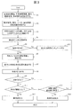
- FIG. 3 is a flowchart showing a cell detection method using the cell detection device 100.
- step S1 the user operates the GUI screen for setting conditions displayed on the output device 81 and the input device 80 to detect the bacteria, the threshold for detecting the bacteria, the culture time (measurement time interval), the maximum culture time, and one culture. Set the amount of medium added to.
- the arithmetic unit 79 stores these set parameters in a storage device (not shown in FIGS. 1 and 2).
- step S2 the user prepares a sample solution that may contain bacteria, a syringe 101 that contains the medium 1, a filter 102, a filter holder 103, a lid 106, a recovery container 105, and a luminescent reagent 3.
- step S3 the user connects the filter holder 103 in which the filter 102 is set to the filtration device (not shown).
- the user connects a funnel (not shown) to the fungus trapping surface side of the filter 102, and pours the sample solution into the funnel to filter.
- the fungus 2 is captured and concentrated on the filter 102, and the solvent is removed.
- a method suitable for the sample such as suction filtration, pressure filtration, and centrifugal filtration can be adopted.
- the filter 102 can be washed and the luminescence measurement background derived from the sample solution can be reduced by further adding a cleaning solution that does not affect the bacteria and filtering.
- the user introduces the luminescent reagent 3 into the recovery container 105, and connects the filter holder 103 to the upper part of the recovery container 105. After that, the user puts a lid 106 on the filter holder 103 to prevent bacteria from entering the filter 102 from the outside world.
- steps S1 to S3 When steps S1 to S3 are completed, the user inputs an operation start instruction to the arithmetic unit 79 by operating the input device 80.
- step S4 the arithmetic unit 79 drives the medium addition device 72 based on the medium addition amount set in step S1 to penetrate the septum 107 of the lid 106 through the needle 108 of the syringe 101, and the syringe 101 through the filter 102.
- the amount of medium 1 to be added can be the minimum amount required for the entire filter 102 to be moistened.
- step S5 the arithmetic unit 79 determines whether the measurement to be executed from now on is the first light emission measurement. In the case of the first measurement (Yes), the process proceeds to step S6.
- step S6 the arithmetic unit 79 drives the medium addition device 72 to pull out the needle 108 of the syringe 101 from the septum 107. After that, the arithmetic unit 79 moves the lid 106, the filter holder 103, and the recovery container 105 to the medium recovery device 74 in a state where they are connected, and transfers the medium in the filter holder 103 (on the filter 102) to the recovery container 105. to recover.
- the medium recovery device 74 is a centrifuge, the medium held in the filter 102 can be dropped to the recovery container 105 side by centrifugal force.
- the recovered medium and the luminescent reagent 3 are mixed (step S7).
- step S8 the luminescence measuring device 109 detects the luminescence generated by the reaction between ATP in the medium and the luminescent reagent 3, and outputs the detection signal to the arithmetic unit 79.
- the arithmetic unit 79 calculates the amount of light emitted based on the detection signal, and stores this in the storage device as the amount of light emitted at the 0th hour of culturing.
- step S9 the arithmetic unit 79 determines whether it was the first measurement. If this is the first measurement, the process returns to step S4. In step S4, the arithmetic unit 79 adds the same amount of medium 1 as in the previous step S4 onto the filter 102. After that, in step S5, the arithmetic unit 79 determines that it is not the first measurement (No), and proceeds to step S10.
- step S10 the arithmetic unit 79 incubates the bacteria on the filter 102 for a predetermined time while keeping the temperature of the filter 102 at an appropriate temperature by the temperature controller 82.
- the temperature may be set according to the bacteria to be detected, such as about 30 to 40 ° C. if the detection target is a bacterium and about 20 to 30 ° C. if the detection target is a mold.
- steps S6 to S9 are executed in the same manner as above.
- the luminescence amount calculated in the second step S8 is stored in the storage device as the luminescence amount for 1 hour after the culturing.
- step S11 the arithmetic unit 79 determines whether the amount of light emitted after culturing is equal to or greater than the threshold value set in step S1. When it is above the threshold value (Yes), the amount of luminescence is increased due to the secretion of ATP in the medium as the bacteria grow, so that the arithmetic unit 79 has detected the bacteria (positive) in step S12. Then, the determination result is output to the output device 81.
- the output device 81 is a monitor, a screen showing a positive result is displayed.
- the output device 81 is a speaker, it emits an alarm sound or the like.
- step S13 the arithmetic unit 79 determines whether the culture time has reached the maximum culture time set in step S1. When the maximum culture time has been reached (Yes), in step S14, the arithmetic unit 79 determines that the bacteria are not detected (negative) and outputs the determination result to the output device 81.
- step S13 If the maximum culture time has not been reached in step S13 (No), the process returns to step S4, and the addition of the medium, the culture, the collection container of the medium, and the luminescence measurement are repeated.
- step S13 it may be determined whether or not the maximum number of measurements has been reached.
- the threshold value set by the user in step S1 may be used for determining the increase in the amount of light emitted in step S11, or the arithmetic unit 79 may automatically calculate from the measurement data. Further, the user may be able to set the condition on the GUI screen for setting the condition displayed on the output device 81 at the stage of step S11. As a result, even if the detection target has different characteristics, the detection conditions can be appropriately set, and the same cell detection device 100 and cell detection method can be used for inspection.
- the determination of the increase in the light emission amount in step S11 is not limited to the method by comparing the light emission amount measured as described above with the threshold value. For example, the difference between the measured light emission amount and the light emission amount at the 0th hour, or the difference between the light emission amount measured this time and the previous light emission amount may be compared with those threshold values.
- the permissible range of the culture time set in step S1 is determined from the growth rate or growth rate of the bacterium, the amount of the medium prepared at the beginning, the amount of the luminescent reagent, and the like.
- the amount of ATP secreted outside the cells is considered to be proportional to the number of bacteria. In general, the number of bacteria in the fastest-dividing strain (such as Escherichia coli) doubles in about 20 minutes. Therefore, in order to detect the growth of bacteria by increasing extracellular ATP, it is considered appropriate that the incubation time is 20 minutes or more, so the measurement interval should be longer than 20 minutes in consideration of measurement variation and measurement sensitivity. can do. For example, 1 hour interval or 2 hour interval.
- the required amount is calculated from the amount of medium added at one time and the set value of the maximum number of measurements. For example, if the amount of medium added to the filter is 50 ⁇ L and the maximum number of times of medium addition is desired to be 20, the amount of medium in the syringe needs to be 1 mL.
- the luminous reagent dilutes and the luminous efficiency decreases in proportion to the concentration each time the medium is mixed with the luminescent reagent, for example, when the dilution ratio of the luminescent reagent is allowed to be diluted 1.5 times.
- the allowable dilution rate of the luminescent reagent can be determined by measuring the relationship between the dilution rate and the luminescence intensity in advance using a standard ATP solution.
- the type of medium to be added can be selected according to the bacteria to be detected.
- bouillon medium or soybean / casein digest medium can be used, but the present invention is not limited to this. It is also possible to use a medium selected for the purpose of detecting only specific bacteria. For example, when the purpose is to detect the Enterobacteriaceae group, an EE bouillon medium for detecting the Enterobacteriaceae group can be used.
- step S4 By reducing the amount of the medium added on the filter 102 as much as possible in step S4, the ATP concentration outside the cells can be increased. On the other hand, it is necessary to spread the medium evenly over the entire filter and add an amount more than sufficient nutrients to the bacteria trapped on the filter. It is also necessary to consider the amount of water that evaporates during incubation.
- the amount of added medium was examined using a PVDF filter having an area of 0.2 cm 2 , a thickness of 0.125 mm, and a pore size of 0.45 ⁇ m.
- the volume of this filter is calculated as area ⁇ thickness, it is 25 ⁇ L.
- 50 ⁇ L of medium was added to this filter to sufficiently moisten the entire filter and then the medium was removed by centrifuge, 5 ⁇ L of medium remained in the filter.
- 50 ⁇ L of the medium was added to the filter, the mixture was placed in a closed container and left in an incubator at 37 ° C. for 2 hours, the water content of the medium on the filter evaporated by about 10 ⁇ L.
- the amount of the medium added to the filter can be 20 ⁇ L, which is obtained by adding the minimum amount required for the luminescence reaction, for example, 5 ⁇ L, to 15 ⁇ L including the residual content and the evaporated content. More preferably, by adding the residual component and the evaporated component to the filter volume to make it 40 ⁇ L or more, the medium can be maintained in a state where the medium is spread over the entire filter even if there is evaporation, and the damage to the bacteria is reduced. Conceivable.
- the amount of the medium added to the filter is about 1/2 to 5 times the area x thickness of the filter and about 1 to 2 times.
- various secretions can be targeted in addition to ATP secreted by the bacterium outside the cells.
- the bacteria can also be detected by adding a substrate that produces fluorescence or luminescence when decomposed by the target enzyme, targeting the enzyme peculiar to the bacterium.
- luciferin derivative that is decomposed by the bacterial esterase to produce luciferin in the medium 1.
- the luciferin derivative is decomposed in proportion to the esterase activity of the bacterium, and luciferin is generated in the medium 1.
- a reagent containing ATP and luciferase as a luminescent reagent, the free luciferin can be quantified.
- bacterial growth can be detected based on the esterase activity.
- a luciferin derivative that is decomposed only into an enzyme specific to the bacterial species to produce luciferin, it is possible to detect only a specific bacterial species.
- a D-luciferin-O- ⁇ -D-glucuronide derivative that is degraded by ⁇ -glucuronidase specific to coliform bacteria
- a luciferin derivative 6-O- ⁇ -Galactopylanosyl that targets ⁇ -galactosidase specific to coliform bacteria.
- -Luciferin and the like a D-luciferin-O- ⁇ -D-glucuronide derivative that is degraded by ⁇ -glucuronidase specific to coliform bacteria.
- the technique of this embodiment can be applied not only to bacteria but also as a method for detecting the activity and proliferation of cultured animal cells and the like. Proliferation of the target cell can be detected by adding a substrate corresponding to various enzymes specific to the target cell.
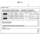
- FIG. 4A is a schematic diagram of a measurement screen 4a showing inspection conditions and inspection status of a plurality of sample solutions.
- a new line is created by clicking the "Create new sample” button, and the sample number, name, and other information are input to set the measurement of the new sample. Can be done.
- the measurement can be started by clicking the "Start” button, and the measurement can be stopped by clicking the "Pause” button.
- the culture start time, the culture elapsed time, the detection positive / negative, or the measurement is in progress for each sample. For samples with test results, the end time is displayed. If the set value of the latest ATP measurement is out of the settable range, an error is displayed.
- the measurement method setting screen opens and the measurement method can be set.
- FIG. 4B is a schematic diagram showing the measurement method setting screen 4b.
- the measurement method setting screen 4b can be called and the measurement method can be set for one or more samples selected on the measurement screen 4a.
- the threshold value which is a criterion for determining that the bacteria are positive
- the measurement time interval (culture time) is set
- the amount of medium added from the medium part to the culture part is set
- the culture time (test time) is set.
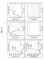
- the graph screen can be called for one or more samples selected on the measurement screen 4a.
- FIG. 4C is a schematic diagram showing a graph screen 4c. As shown in FIG. 4C, on the graph screen 4c, the time course of the measured value, the determination time and result when a positive / negative determination is made, the threshold value used for the determination, and the like are displayed for the selected sample. By using the graph screen 4c, the progress of measurement can be visually confirmed for a plurality of samples.
- the cell detection device 100 includes a syringe (medium container, medium addition device) for accommodating a medium, a filter 102 (culture container) for holding a bacterium 2, a centrifuge, and the like. It has a culture medium recovery device and a recovery container 105 for accommodating the luminescent reagent 3.
- the cell detection device 100 adds a part of the medium 1 in the syringe 101 to the filter 102 by the syringe 101, collects the medium 1 in contact with the bacterium 2 in the recovery container 105 by the medium recovery device, and collects the medium 1 in contact with the bacterium 2 in the recovery container 105, and the luminescence measuring device 109.
- the luminescence from the luminescent reagent 3 is measured by. Since the medium in contact with the bacterium is recovered from the filter 102 in this way, it is possible to add a part of the medium 1 to the filter 102 holding the bacterium 2 again and culture the medium. Therefore, the cell detection device 100 may repeat a series of operations of contacting a part of the above-mentioned medium 1 with the bacterium 2, moving the medium 1 in contact with the bacterium 2, and detecting light a plurality of times every culture time. can.
- the cell detection device 100 can collect the extracellular secretion of the bacterium 2 captured on the filter 102 at a high concentration and measure the luminescence at any culture time. Therefore, the presence or absence of bacterial growth can be detected quickly and with high sensitivity without destroying the bacterial 2. Moreover, since the detected bacterium 2 is non-destructive, it is possible to perform other tests on this bacterium 2.
- FIG. 5A is a schematic cross-sectional view showing the cell detection device 200 according to the second embodiment, and shows a state when the medium 1 is added to the filter 102 for the first time.
- the cell detection device 200 includes five collection containers 105a to 105e (plural collection containers). Further, the light emitting reagent 3 is not introduced in the recovery container 105 in advance. Other configurations are the same as those of the cell detection device 100 of the first embodiment.
- the filter holder 103 and the lid 106 are shown in a simplified manner.
- the number of collection containers 105 is five in FIG. 5A, but is selected according to the number of required light emission measurements.
- the plurality of collection containers 105 are, for example, individual microtubes, and can be individually installed in a centrifuge, a light emission measuring device, or a temperature controller.
- the filter holder 103 having the filter 102 is connected to the first collection container 105a, and the needle 108 of the syringe 101 is pierced into the septum of the lid 106 to pierce a part of the medium 1.
- the needle 108 of the syringe 101 is pulled out.
- the collection container 105a and the filter holder 103 connected the medium 1 on the filter 102 is collected in the collection container 105a by setting it in a centrifuge and centrifuging.
- FIG. 5B shows the state after the medium 1 is collected in the first collection container 105a.
- the syringe 101 and the filter holder 103 are retracted from the first collection container 105a from which the medium 1 has been collected, and these are set in the second collection container 105b.
- the light emitting reagent 3 is added to the first collection container 105a using a syringe 201 containing the light emitting reagent 3, and the light emission measuring device 109 measures the light emission.
- the light emission measuring device 109 measures the light emission.
- the syringe 201 is attached to a drive device (light emitting reagent addition device) that controls the vertical movement of the syringe 201 itself and the sliding of the plunger of the syringe 201.
- a drive device light emitting reagent addition device
- FIG. 6 is a functional block diagram of the cell detection device 200 according to the second embodiment. As shown in FIG. 6, in the cell detection device 200, the culture medium recovery unit 75 and the luminescent reagent unit 76 are separately arranged, and the luminescence reagent addition device 77 is connected to the luminescence reagent unit 76. Other points are the same as those of the cell detection device 100 of the first embodiment shown in FIG.
- the luminescent reagent section 76 is, for example, a storage section for the luminescent reagent 3 of the syringe 201 shown in FIG. 5 (b).
- the luminescent reagent addition device 77 is, for example, a syringe 201 and a driving device thereof.
- the driving device of the syringe 201 includes a component for fixing the syringe 201, a motor for moving the component, a motor for pushing the plunger of the syringe 201 by a certain distance, and a motor for discharging the luminescent reagent 3.
- the arithmetic unit 79 controls the operation of the luminescent reagent addition device 77 in addition to the operation of the culture medium addition device 72 and the culture medium recovery device 74.
- the user can determine the amount of the luminescent reagent 3 to be added via the input device 80, and the arithmetic unit 79 controls the operation of the luminescent reagent adding device 77 according to the parameters.
- steps S1 to S6 are executed in the same manner as above, and the medium 1 is collected in the first collection container 105a.
- the arithmetic unit 79 retracts the filter holder 103 from the first collection container 105a by a mechanism (not shown) and connects them to the new second collection container 105b.
- step S7 the arithmetic unit 79 drives the luminescent reagent adding device 77 to add the luminescent reagent 3 from the syringe 201 to the first collection container 105a.
- steps S8 and S9 are carried out in the same manner as in the first embodiment, and the process returns to step S4, and the arithmetic unit 79 is a filter set in the second collection container 105b.
- the medium is added to 102 from the syringe 101.
- step S5 it is determined that this is the second measurement, the process proceeds to step S10, and the cells are cultured for a predetermined time.
- step S6 the medium 1 is collected in the second collection container 105b.
- the arithmetic unit 79 retracts the filter holder 103 from the second collection container 105b by a mechanism (not shown) and connects them to the new third collection container 105c.
- step S7 the arithmetic unit 79 drives the luminescent reagent adding device 77 to add the luminescent reagent 3 from the syringe 201 to the second collection container 105b.
- steps S8 to S14 are carried out in the same manner as in the first embodiment. The above operation is repeated until a positive or negative detection result is obtained in the light emission measurement in the second collection container 105b or later.
- the cell detection device 200 has a plurality of collection containers, and after culturing the bacteria on the filter 102 in different collection containers for each repeated luminescence measurement.
- the medium 1 is recovered and mixed with the luminescent reagent 3.
- the mixing ratio of the recovered medium 1 and the luminescent reagent 3 can be kept constant, so that luminescence measurement can be performed with the same sensitivity at any culture time. Therefore, the accuracy of detecting bacteria is improved.
- the detection target was Staphylococcus aureus (S. aureus), and the bacterial solution of Staphylococcus was used as a sample solution.
- Three types of bacterial counts were prepared: 0CFU (Colony forming unit), 10CFU or 100CFU.
- microtube was replaced with a new one (first collection container), and 50 ⁇ L of SCD medium was added to the filter. This was centrifuged and the medium added to the filter was collected in a microtube.
- the filter was transferred to a new microtube (second collection container), 50 ⁇ L of SCD medium was added to the filter again, and the filter was covered. After incubating this at 37 ° C. for 2 hours, the medium was collected in a microtube (second collection container) by centrifuge. 30 ⁇ L of the luminescent reagent was added to the collected medium, and the amount of luminescence was measured.
- FIG. 7A is a graph showing the results of two inspections of three types of sample solutions.
- the horizontal axis of the graph of FIG. 7A is the culture time, and the vertical axis is the amount of luminescence (CPS: Count per second) proportional to the amount of ATP.
- CPS Count per second
- the ATP value at each time corresponds to the amount of extracellular ATP secreted into the medium during the 2-hour incubation.
- the ATP value at the 4th hour is the total amount of ATP secreted by the fungus into the medium at the 2nd to 4th hours.
- FIG. 7 (b) is a graph comparing the amount of ATP outside the cells and the amount of ATP inside the cells at the 6th hour of culture.
- the vertical axis of FIG. 7B is the amount of ATP (amol).
- the two bar graphs on the left are obtained by converting the unit of the measurement result of the amount of extrabacterial ATP in 10 CFU of FIG. 7 (a) into amol. That is, staphylococci were cultured at an initial bacterial count of 10 CFU, and the amount of ATP secreted outside the cells during the 4th to 6th hours was plotted.
- the two bar graphs on the right side show the results of measuring the amount of intracellular ATP after measuring the extracellular ATP using a sample of 10 CFU (results of two measurements). That is, it is the result of measuring the amount of ATP contained in the cells after culturing the staphylococci at the initial number of bacteria of 10 CFU for 6 hours.
- the average amount of ATP outside the cells was 15,000 amol, and the amount of ATP inside the cells was 120,000 amol. Therefore, it can be seen that the amount of ATP outside the cells was about 1/8 of the amount of ATP inside the cells.
- Method 1 When a sample is added to a medium and cultured, and ATP in the cells is measured (bacterial destruction). This is a method in which 9 mL of SCD medium is added to 1 mL of a sample of 10 CFU / 1 mL of staphylococcus, and 30 ⁇ L of each is separated while culturing to measure ATP in the cells.
- the initial bacterial concentration after addition of SCD medium is 10 CFU / 10 mL.
- 30 ⁇ L of the culture solution was separated, 10 ⁇ L of the free ATP scavenging reagent and 10 ⁇ L of the intracellular ATP extraction reagent were added, 30 ⁇ L of the luminescent reagent was added, and the luminescence was measured to calculate the ATP amount. Then, it is calculated as 360amol (120,000amol ⁇ 10 mL ⁇ 30 ⁇ L).
- Method 2 When a sample is added to the medium and cultured, and extracellular ATP is measured (non-destructive bacteria).
- the culture was carried out in the same manner as in Method 1, 30 ⁇ L of the luminescent reagent was added to 50 ⁇ L of this culture solution, the amount of luminescence was measured, and the amount of ATP was calculated.
- the amount of ATP was 75 amol (15000 amol ⁇ 10 mL ⁇ 50 ⁇ L).
- Method 3 When culturing bacteria on a filter in a small amount of medium (second embodiment) 1 mL of the sample is filtered through a filter, and 10 CFU of the bacterium is captured on the filter and concentrated. To this, 50 ⁇ L of SCD medium is added, and the cells are cultured at 37 ° C. for 2 hours, and the medium is removed three times. When 30 ⁇ L of the luminescent reagent is added to 50 ⁇ L of the medium collected for the third time and luminescence is measured to calculate the amount of ATP, the amount of ATP is 15,000 amol.
- the sensitivity can be improved by about 50 times even if the bacteria are not destructive, and the bacteria can be detected more quickly, as compared with the method of measuring the luminescence.
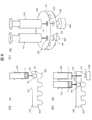
- FIG. 8A is a schematic cross-sectional view showing the cell detection device 300 according to the third embodiment.
- the cell detection device 300 includes a closed container 301 whose inside is sealed.
- the closed container 301 has a disk 302 forming the upper surface and a disk 303 forming the bottom surface.
- One filter holder 103 (culture container) for holding the filter 102 is attached to the disk 302, an opening of the filter holder 103 is formed in the disk 302, and the filter holder 103 is closed by the septum 107.
- a collection container 305 in the form of a plurality of wells is formed on the disk 303.
- the light emitting reagent 3 is not introduced in the recovery container 305 in advance.
- At least one of the disc 302 or the disc 303 is configured to be rotatable about its center as a rotation axis.
- the filter 102 can be positioned above each collection container 305.
- the rotation of the disk 302 or the disk 303 is controlled by, for example, a rotary electric machine driven based on an instruction of the arithmetic unit.
- the space between the disks 302 and 303 is sealed.
- sealed means that there is no gap through which bacteria can invade from the outside.
- the inside of the closed container 301 can be filled with a gas having a composition different from that of the outside air for anaerobic culture, and the airtightness between the inside and the outside is maintained by the closed structure.
- FIG. 8B shows the state after the medium 1 is collected in the first collection container 305.
- the syringe 101 and the filter holder 103 are retracted from above the first collection container 305 from which the medium 1 has been collected, and these are stopped above the second collection container 305.
- the disk 302 is provided with an opening covered with a septum 304.
- a syringe 201 containing the luminescent reagent 3 is used for the first collection container 305, the luminescent reagent 3 is added through the septum 304 with the needle of the syringe 201, and the luminescence is measured by the luminescence measuring device 109. I do.
- FIG. 8 (c) is a perspective view showing the state of FIG. 8 (b).
- the internal structure is shown so as to pass through the side wall surface of the closed container 301.
- the septums 107 and 304 covering the openings provided in the disk 302 are located directly above the two collection containers 305 provided in the disk 303, respectively.
- step S3 the user sets the filter 102 that has captured the bacteria 2 by filtering the sample solution in the filter holder 103 of the disk 302.
- the user may set the filter 102 on the disk 302, add the sample solution to the filter 102, centrifuge the closed container 301, and store the filtrate in one of the plurality of collection containers 305. good.
- the method of the present embodiment is different from the second embodiment in that the positional relationship between the filter 102 and each collection container 305 is changed by rotating the disk 302 or 303.
- the filter 102 for culturing the bacterium and the recovery container 305 for measuring luminescence are arranged in the internal space of the closed container 301, and the bacterium is cultured. And the recovery of the medium 1 and the luminescence measurement are carried out in the closed container 301.
- the gas composition in the closed container 301 can be controlled, the culture conditions can be kept anaerobic or aerobic depending on the type of the bacterium to be detected.
- FIG. 9A is a schematic cross-sectional view for explaining a method of filtering a sample solution using the filter 102.
- the filter 102 is, for example, a filter having a volume of 100 ⁇ L.
- the filter 102 is held in the annular filter holder 403.
- a large amount of liquid sample can be filtered by connecting the funnel 5 to the cell collection surface side of the filter 102 and connecting the filtration table 6 to the opposite surface.
- a suction pump (not shown) to the filtration table 6 and performing suction filtration, bacteria in the sample can be collected and concentrated on the filter 102.
- FIG. 9B is a schematic cross-sectional view showing the cell detection device 400 according to the fourth embodiment.
- the structure of the medium container accommodating the medium 1 and the culture container in which the culture is performed has the same structure as the cell detection device 100 to the third embodiment. It is different from 300.
- the syringe 401 is provided with a check valve 409 that controls the dropping and sealing of the medium 1.
- the check valve 409 allows the medium 1 to flow only in the direction of the filter 102 from the syringe 401. During culturing, the check valve 409 prevents the diffusion of cell-derived substances from the filter 102 into the medium 1.
- the adapter 404 is provided with a valve 410 and a capillary 408 for draining the medium 1 that has passed through the filter 102.
- the valve 410 is configured to allow the medium to flow from the filter 102 to the capillary 408 only when a certain pressure or higher is applied, and the medium of the filter 102 is on the capillary 408 side due to gravity while the cells are being cultured on the filter 102. Prevents flow to.
- the syringe 401 is a drive device (medium addition device) that controls the vertical movement of the syringe 401 itself, the sliding of the plunger of the syringe 401, the drive of the check valve 409, and the drive of the valve 410. Attached to.
- the luminescent reagent 3 is dispensed, for example, in an amount of 200 ⁇ L into a plate-shaped container having a plurality of wells 405 (plural collection containers).
- the well 405 is made of a material that does not transmit light having a wavelength of light emission so that light emission in the adjacent well 405 does not interfere with the measurement. It has become.
- Each well 405 is covered with a seal 406 to keep it sealed. As the seal 406, a rubber seal that can maintain the airtightness even if the capillary 408 penetrates, an aluminum material that prevents deterioration of the light emitting reagent 3, and the like can be used.
- the light emission measuring device 109 is provided with a cover 416 that covers the periphery of one well 405, whereby it is possible to prevent light from adjacent wells 405 from being detected.
- the cell detection method according to the fourth embodiment is substantially the same as the method of the second and third embodiments using a plurality of collection containers.
- the arithmetic unit actually drives each drive device to drive the syringe 401 and the like, but in order to simplify the explanation, the main body of the operation may be simply described as the arithmetic unit.
- the arithmetic unit may operate the syringe 401 to flow the medium 1 and wash the flow path to the filter 102 and the capillary 408. At this time, the medium 1 discharged from the capillary 408 is discarded.
- the amount of the medium 1 added to the filter 102 at one time is the total amount (for example, 200 ⁇ L) of the volumes in the space 402, the valve 410, and the capillary 408 in which the filter 102 is present. Can be done.
- the arithmetic unit inserts the seal 406 through the capillary 408 into one well 405, drops 200 ⁇ L of the medium 1 into the well 405, and mixes it with the luminescent reagent 3.
- the light emission measuring device 109 detects the light emitted by the reaction through the transparent window 415 and transmits the detection signal to the arithmetic unit.
- the arithmetic unit calculates the amount of light emission corresponding to the detection signal, and sets this as the light emission at the 0th hour.
- the arithmetic unit draws out the capillary 408 from the well 405 in which the light emission measurement was performed at the 0th hour, keeps the filter 102 at, for example, 37 ° C. by a temperature controller, and cultures the bacteria on the filter 102.
- the arithmetic unit After culturing for 2 hours, the arithmetic unit penetrates the seal 406 through the capillary 408 and inserts it into the well 405 different from the 0th hour. Then, 200 ⁇ L of the medium 1 is sent by the syringe 401, and the medium containing the substance secreted by the cells on the filter 102 is dropped into the well 405 and mixed with the luminescent reagent 3.
- the light emission measuring device 109 detects the light emitted by the reaction through the transparent window 415 and transmits the detection signal to the arithmetic unit.
- the arithmetic unit calculates the amount of light emission corresponding to the detection signal, and this is used as the light emission for the second hour.
- the arithmetic unit compares the amount of light emitted at the 0th hour with the amount of light emitted at the 2nd hour, and if a significant increase in the amount of light emitted is observed at the 2nd hour, the bacterium is positive. In other cases, the same operation is repeated until an increase in the amount of light emitted is detected as compared with the amount of light emitted at the 0th hour.
- the method is not limited to the method of determining positive or negative by comparing the measured luminescence amount with the luminescence amount at the 0th hour, and the determination may be made by comparison with a predetermined threshold value or the like.
- the cell detection device 400 is used in combination with the syringe 401 that contains and drops the medium 1 and the filter 102 that captures the bacteria, and is inside the syringe 401.
- the medium 1 of the above and the medium 1 added to the filter 102 are separated and arranged. As a result, it is not necessary to move the syringe containing the medium and the filter holder 403 having the filter 102 separately, so that the operation is simple.
- the dispensing mechanism of the luminescent reagent 3 becomes unnecessary, and the configuration of the entire apparatus can be simplified.
- the mixing ratio of the recovered medium 1 and the luminescent reagent 3 can be kept constant, and eventually. Luminescence can be measured with the same sensitivity even during the culture time of. Therefore, the accuracy of detecting bacteria is improved.
- FIG. 10A is a schematic cross-sectional view showing the filter cartridge 502 of the cell detection device 500 according to the fifth embodiment.
- the filter cartridge 502 includes a filter holder 503, a mesh 504, lids 506 and 507, flow paths 508 and 509, and plugs 510 and 511.
- the filter 102 is fixed on the mesh 504 held by the annular filter holder 503.
- the mesh 504 serves to support the filter 102 when the strength of the filter 102 is weak.
- the filter holder 503 is provided with a flow path 508 and a flow path 509, and the flow path 508 and the flow path 509 are sealed with plugs 510 and 511, respectively, before the addition of the medium.
- the flow path 508 is provided on the fungus trapping surface side of the filter 102, and the flow path 509 is provided on the surface side opposite to the fungus trapping surface of the filter 102.
- a funnel is attached to the fungus trapping surface side of the filter 102, a filtration table is attached to the mesh 504 side, and the sample solution is supplied from the funnel to filter the sample and capture the cells in the filter 102.
- disk-shaped lids 506 and 507 (members defining the space) are attached to both sides of the filter 102 so as to surround the filter 102.
- FIG. 10B is a top view showing a configuration in which a medium is added to the filter cartridge 502.
- a medium container 501 is connected to the flow path 508 via a check valve 513 and a liquid feed pump 512, and a capillary 515 is connected to the flow path 509 via a valve 514.
- the flow path 508 is connected to the fungus trapping surface of the filter 102, and the flow path 509 is connected to the opposite surface.
- the medium 1 is supplied to the bacteria trapping surface side of the filter 102 via the check valve 513 and the flow path 508 by the liquid feed pump 512, and flows through the filter 102 to the flow path 509. That is, the flow direction of the medium 1 is substantially parallel to the filter surface. By flowing the medium substantially parallel to the filter surface, the medium can be spread over the entire filter surface even with a small amount of medium as compared with the case where the medium is flowed vertically.
- the cell detection method using the cell detection device 500 of the present embodiment is substantially the same as the cell detection method of the second to fourth embodiments described above, and will be briefly described below.
- the arithmetic unit actually drives each drive unit to drive the liquid feed pump 512 and the like, but for the sake of simplification of the explanation, the main body of the operation may be simply described as the arithmetic unit.
- the arithmetic unit flows a sufficient amount of the medium 1 by the liquid feed pump 512 to wash the filter 102 and the flow paths 508 and 509, and discharges the filter 102 from the capillary 515.
- the operation of cell detection can be performed using a plate having a plurality of wells (collection containers) into which the luminescent reagent has been dispensed in advance, as in the fourth embodiment.
- the arithmetic unit sends a predetermined amount of medium 1 from the medium container 501 into the filter holder 503 by driving the liquid feed pump 512, collects the medium 1 from the capillary 515 into the first well, and emits light.
- Luminous measurement is performed by a measuring device. After that, the arithmetic unit retracts the filter cartridge 502 from the first well, sends a predetermined amount of the medium 1 into the filter holder 503 again, incubates for a predetermined time, and then collects the filter cartridge 502 from the capillary 515 to the second well. Then, the light emission is measured by the light emission measuring device. In this way, the arithmetic unit repeats the operation of adding the medium 1 to the filter 102, culturing for a predetermined time, and measuring the luminescence.
- the cell detection device 500 includes a filter cartridge 502 having a configuration in which the medium 1 is added from a direction substantially parallel to the surface of the filter 102.
- a filter cartridge 502 having a configuration in which the medium 1 is added from a direction substantially parallel to the surface of the filter 102.
- FIG. 11 is a schematic cross-sectional view showing the filter cartridge 602 of the cell detection device 600 according to the sixth embodiment.
- the filter cartridge 602 (culture container) has substantially the same configuration as the filter cartridge (FIG. 10) of the fifth embodiment, but the fixing member 603 is adhered to the back surface of the lid 506. It differs in that.
- the fixing member 603 is in contact with the fungus trapping surface of the filter 102.
- the fungus 2 captured by the filter 102 is fixed by being sandwiched between the filter 102 and the fixing member 603.
- the internal volume of the filter cartridge 602 including the fixing member 603 can be within 5 times the volume (area ⁇ thickness) of the filter 102.
- the material of the fixing member 603 can be used without particular limitation as long as it is the same material as the filter 102, a material such as an agar medium (gel) that can fix the position of the fungus 2 and does not affect the fungus 2.
- a transparent gel is used as the fixing member 603
- the bacteria 2 are detected using the cell detection device 600, the bacteria 2 are further cultured to form visible colonies, and the filter cartridge 602 is taken out. It can be observed as it is.
- the cell detection device 600 includes a filter cartridge 602 having a configuration in which the medium 1 is added from a direction substantially parallel to the surface of the filter 102, and the back surface of the lid 506 of the filter cartridge 602. Is provided with a fixing member 603 for fixing the position of the fungus 2.
- the viable cell count can be counted by forming visible colonies by culturing after detecting the positive bacteria.
- FIG. 12 is a schematic view showing the cell detection device 700 according to the seventh embodiment.
- the cell detection device 700 includes a medium container 501 (medium container) for accommodating the medium 1, a liquid feed pump 512 (medium addition device), a filter cartridge 502 (culture container), a flow path 701, and a switching valve. 702 (selection mechanism, medium recovery device), and a plurality of wells 705 (several recovery containers) containing a luminescent reagent 3 are provided.
- the flow path on the side where the medium 1 is discharged is connected to the flow path 701, and the flow path 701 is connected to the switching valve 702.
- the switching valve 702 has a flow path 703 that is switched so as to communicate with each of the plurality of wells 705, and switching of the flow path 703 is controlled by a valve controller (not shown in FIG. 12) connected to the arithmetic unit. NS.
- the cell detection method using the cell detection device 700 of the present embodiment is substantially the same as the cell detection method of the second to fourth embodiments described above, and will be briefly described below.
- the arithmetic unit Before performing the luminescence measurement, the arithmetic unit flows a sufficient amount of the medium 1 by the liquid feed pump 512 to wash the filter and the flow path 701 and discharge the medium 1. Next, the arithmetic unit connects the flow path 701 to the switching valve 702. Next, as in the fifth embodiment, the arithmetic unit sends a predetermined amount of the medium 1 to the filter cartridge 502 for each culture time, cultures for a predetermined time, and then switches the switching valve 702 to perform the culture. The medium 1 is collected in a different well 705 each time, mixed with a luminescent reagent to cause a luminescence reaction, and luminescence measurement is performed by a luminescence measuring device.
- the cell detection device 700 has a well in which the flow path 701 connected to the filter cartridge 502 is one well as a configuration for collecting the medium 1 in the wells 705 different for each culture time. It has a switching valve 702 that switches the flow path 703 so as to communicate with the 705. As a result, it is possible to measure the luminescence for each culture time while maintaining the hermeticity in the culture medium container 501, the filter cartridge 502 and the well 705, so that contamination from the outside during the culture can be prevented. Further, since it is not necessary to move the filter cartridge 502 to retract from each well 705 or to insert the flow path 701 into each well 705, there is no need for a space for moving the filter cartridge 502, and the apparatus. Can be miniaturized.
- FIG. 13 is a schematic cross-sectional view showing the culture medium container 801 and the filter cartridge 802 of the cell detection device 800 according to the eighth embodiment.
- the filter cartridge 802 (culture container) includes an annular filter holder 803 for holding the filter 102, adapters 806 and 807, valves 809, and capillary 808.
- the filter holder 803 is sandwiched between the adapters 806 and 807 (members that define the space). A recess is formed on the surface of the adapters 806 and 807 facing the filter 102. As a result, a space for accommodating the filter 102 is formed.
- the adapter 806 is provided with two flow paths 804 that communicate this space with the outside.
- a medium container 801 (a plurality of medium containers) for accommodating the medium 1 is connected to each of the two flow paths 804.
- a valve 805 is provided at the boundary between the flow path 804 and the medium container 801 to separate the space in which the filter 102 is housed from the medium 1.
- the medium container 801 is sterilized and contained in the amount of medium 1 required for one culture calculated in advance.
- the bacteria that can grow can be detected according to the type of the medium, the bacteria can be categorized according to which medium the bacteria contained in the sample could or could not grow.
- a device capable of compressing the medium container 801 (a pressure can be applied to the medium container 801) is connected to the medium container 801, and by applying a pressure equal to or higher than a predetermined value to the medium container 801.
- Medium 1 in the medium container 801 passes through the valve 805 and is added onto the filter 102.
- the adapter 227 is provided with a capillary 808 connected to the space in which the filter 102 is housed.
- a valve 809 is provided between the space in the adapters 806 and 807 and the capillary 808, and the drive of the valve 809 is controlled by a drive device (medium addition device) (not shown).
- the cell detection method using the cell detection device 800 of the present embodiment is substantially the same as the cell detection method of the second to fourth embodiments described above, and will be briefly described below.
- a sufficient amount of the medium 1 is flowed from the flow path 804 to wash and discharge the filter 102 and the capillary 808.
- the medium container 801 is connected to each flow path 804.
- one medium container 801 is compressed every culture time, and the entire amount of the medium 1 in the medium container 801 is sent to the filter cartridge 802 and cultured for a predetermined time. .. That is, a part of the total amount of the medium 1 in all the medium containers 801 is sent to the filter cartridge 802.
- the culture medium 1 after culturing is collected in a different well each time, mixed with a luminescent reagent and subjected to a luminescence reaction, and luminescence measurement is performed.
- the cell detection device 800 has a plurality of medium containers 801 containing the amount of medium 1 required for one culture, and is connected to the plurality of medium containers 801 filter cartridge 802. Will be done. This makes it possible to easily add a small amount of medium to the filter 102 multiple times without the need for a precise mechanical mechanism.
- the bacteria detected by the method of each embodiment are non-destructive and can be used for subsequent analysis.
- a cell detection device capable of counting the number of colonies of the detected bacteria has been described. Therefore, in the ninth embodiment, we propose another cell detection device capable of counting the number of colonies of the detected bacteria.
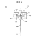
- FIG. 14 is a schematic cross-sectional view showing the filter cartridge 902 of the cell detection device 900 according to the ninth embodiment.
- the filter cartridge 902 (culture vessel) includes an annular filter holder 903 holding the filter 102, a partition wall 904, adapters 906 and 907, valves 905 and 909, and a capillary 908.
- the filter holder 903 is sandwiched between the adapters 906 and 907.
- a recess is formed on the surface of the adapters 906 and 907 facing the filter 102.
- a space for accommodating the filter 102 is formed.
- a valve 905 is provided in the recess of the adapter 906, and a medium container (not shown in FIG. 14) is connected to the valve 905.
- a valve 909 is provided in the recess of the adapter 907, and a capillary 908 is connected to the valve 909.
- the partition wall 904 is arranged on the cell capture surface of the filter 102.
- the septum 904 divides the cell capture surface of the filter 102 into a plurality of cells. Bacteria 2 that have entered each square cannot move to another square.
- the shape of the upper surface of the partition wall 904 is not particularly limited, for example, a grid pattern, a radial pattern, a concentric pattern, or any combination thereof. However, from the viewpoint of accurately counting the bacteria 2, the shape of the partition wall 904 can be selected so that the areas of the cells are substantially equal to each other.
- the partition wall 904 can be made of resin, for example.
- the cell detection method using the cell detection device 900 of the present embodiment is substantially the same as the cell detection method of the second to fourth embodiments described above, and will be briefly described below.
- the filter 102 is installed in the filter holder 903, and the sample solution is added from above the filter 102 to perform filtration with the partition wall 904 arranged on the filter 102. At this time, the fungus 2 contained in the sample is captured by any of the cells.
- the filter holder 903 is sandwiched between the adapters 906 and the adapters 906 and 907, and the filter cartridge 902 is assembled.
- the medium when the medium is added via the valve 905, the medium can spread over the entire surface of the filter 102 due to the capillary phenomenon.
- the medium can be spread over the entire surface of the filter 102 by rotating the filter cartridge 902 on the central axis 910 of the filter cartridge 902 and generating a centrifugal force from the center of the filter 102 toward the edge (diametrically outward). You can also.
- the added medium is collected from the valve 909 and the capillary 908, and the luminescence is measured.
- the addition of the medium, the culture for a predetermined time, the recovery of the medium, and the measurement of luminescence are repeated, and when an increase in the amount of luminescence is observed, the bacteria are positive.
- the adapter 907 is removed from the filter cartridge 902, the filter 102 is placed on an appropriate agar medium or liquid medium, and further culturing is performed to promote cell proliferation in each mass by visual or optical measurement means. Can be confirmed. If the number of cells contained in the original sample is smaller than the total number of cells, the number of cells in which cell proliferation is observed can be considered as the number of viable cells in the original sample.
- a partition wall 904 that forms a mass on the cell capture surface is provided on the filter 102.
- the number of viable bacteria can be counted by further culturing after detecting the bacteria.
- the medium added to the filter is collected by centrifugation in a collection container arranged below the filter.
- a tenth embodiment proposes an example in which the collection container is arranged substantially on the same plane as the filter.
- FIG. 15A is a schematic cross-sectional view showing the filter cartridge 1002 and the recovery container cartridge 1010 of the cell detection device 1000 according to the tenth embodiment.
- the collection container cartridge 1010 is formed in an annular shape and is provided around the annular filter cartridge 1002.
- the filter cartridge 1002 includes an annular filter holder 1003 for holding the filter 102, upper and lower lids 1006 for sealing the inside of the filter holder 1003, and a rotation shaft 1009 provided perpendicular to the filter 102 at the radial ends of the filter holder 1003. Have.
- the filter holder 1003 has a mesh 1004, and a filter 102 on which the fungus 2 is captured is placed on the mesh 1004.
- a septum 1007 is provided at the center of the upper lid 1006.
- the culture medium can be supplied to the space in which the filter 102 is contained by penetrating the septum 1007 through the needle of the capillary or the syringe containing the culture medium connected to the culture medium storage container.
- the filter holder 1003 is provided with a flow path 1008 substantially parallel to the filter 102.
- a plurality of collection containers 1005 are formed along the circumferential direction of the collection container cartridge 1010.
- One of the collection containers 1005 communicates with the flow path 1008 (selection mechanism) of the filter holder 1003.
- the internal space of the recovery container 1005 is divided into upper and lower parts by a destructible seal 1011, and the luminescent reagent 3 is housed on the seal 1011.
- the space below the seal 1011 communicates with the flow path 1008 of the filter holder 1003.
- the upper surface on the side where the luminescent reagent 3 is housed can also be destructible. Thereby, for example, the needle penetrating the upper surface of the recovery container 1005 and the seal 1011 can destroy them, and the light emitting reagent 3 can be added to the space below the seal 1011.
- the collection container cartridge 1010 When communicating the flow path 1008 and the collection container 1005, the collection container cartridge 1010 is aligned with the filter cartridge 1002 by rotating it.
- the filter cartridge 1002 is centered on the rotation shaft 1009 in a state where the filter cartridge 1002 and the collection container cartridge 1010 are assembled (the state in which the flow path 1008 and the collection container 1005 are communicated with each other). It has a rotation mechanism (medium recovery device) that rotates the container. Centrifugal force is applied to the medium existing in the space in which the filter 102 is housed by the rotation about the rotation axis 1009, and the medium moves in the direction away from the rotation axis 1009.
- a rotation mechanism medium recovery device
- FIG. 15B is a schematic top view showing the filter cartridge 1002 and the collection container cartridge 1010. As shown in FIG. 15B, the flow path 1008 is provided on the opposite side of the rotation axis 1009 by 180 °. Due to such a positional relationship, the medium in the filter cartridge 1002 can be recovered in the recovery container 1005 with a high recovery rate and a small amount of residual liquid.
- the cell detection method using the cell detection device 1000 of the present embodiment is substantially the same as the cell detection method of the second to fourth embodiments described above, and will be briefly described below.
- the sample solution is filtered by the filter 102 of the filter cartridge 1002 to capture the bacteria 2.
- the lid 1006 and the rotating shaft 1009 are attached to the filter cartridge 1002
- the collection container cartridge 1010 is attached around the filter cartridge 1002, and the flow path 1008 and the first collection container 1005 are communicated with each other.
- the medium is added into the filter cartridge 1002 from the septum 1007, and the filter cartridge 1002 is rotated around the rotation shaft 1009 by a rotation mechanism, and the first collection container is used.
- the medium is collected in the space below the seal 1011 of 1005.
- a syringe needle for destroying the collection container 1005 and the seal 1011 is used to destroy them, and the medium collected in the first collection container 1005 is reacted with the luminescent reagent.
- a light emission measuring device is arranged at a position where light emission from the bottom surface of the collection container 1005 can be detected, and light emission measurement is performed.
- the collection container cartridge 1010 is rotated with respect to the filter cartridge 1002 so that the flow path 1008 and the second collection container 1005 communicate with each other.
- the medium was added from the septum 1007 into the filter cartridge 1002, and after culturing for a predetermined time, the filter cartridge 1002 was rotated around the rotation shaft 1009 by a rotation mechanism, and the second one. The medium is collected in the space under the seal 1011 of the collection container 1005.
- the filter cartridge 1002 rotates about the shaft 1009.
- the medium can be recovered from the filter 102 into the recovery container 1005 by centrifugal force, so that a high recovery rate can be achieved.
- a medium addition device that adds a part of the prepared medium to the culture vessel that holds the cells to be detected, and a medium addition device.
- a medium recovery device for recovering the medium from the culture container, and a medium recovery device.
- a cell detection device comprising a detection device for detecting light from a luminescent reagent mixed with the collected medium.
- Specified matter 2 characterized in that the volume of the part of the medium added to the culture vessel by the medium addition device is 1 ⁇ 2 or more and 5 times or less the value obtained by multiplying the area and the thickness of the filter.
- the cell detection device according to.
- the luminescent reagent contains luciferase and contains The cell detection apparatus according to Specific Item 1, wherein the light is emitted from the cells by a reaction between adenosine triphosphate or luciferin and the luciferase generated in the medium.
- the above-described item 1 is characterized in that the medium recovery device further includes a selection mechanism for connecting an arbitrary recovery container and the culture container among a plurality of recovery containers in which a part of the medium is recovered. Cell detector.
- the specific item characterized in that the medium addition device adds the entire amount of the medium in the medium container to the culture container from any medium container among a plurality of medium containers each accommodating the partial medium.
- the cell detection device according to 1.
- the medium container, the culture container, and the recovery container move the medium in the order of the medium container containing the prepared medium, the culture container, and the recovery container containing the medium collected from the culture container.
- the cell detection device according to Specific Item 1, further comprising a light emitting reagent adding device for adding the light emitting reagent to the medium recovered by the medium recovery device.
- ⁇ Specific matter 14> 5 The cell detection device according to the specific item 5, wherein the selection mechanism is a valve that switches a flow path for communicating the culture container and one of the plurality of collection containers.
- the cell detection apparatus further comprising a partition wall that is arranged on a surface of the filter that holds the cells and that divides the surface into a plurality of cells.
- the plurality of collection containers are arranged around the culture container, and the plurality of collection containers are arranged around the culture container.
- the selection mechanism is a flow path for communicating the culture container and one of the plurality of collection containers.
- the cell detection device according to the specific item 5, wherein the culture medium recovery device rotates the culture container in a state where one of the culture container and the plurality of recovery containers communicates with each other.
- the culture vessel has a filter with a pore size smaller than the size of the cells.
- the cell detection method is 17.
- ⁇ Specific matter 20> 19 Cell detection according to Specific Item 19, wherein the volume of the part of the medium added to the culture vessel is 1 ⁇ 2 or more and 5 times or less the value obtained by multiplying the area and the thickness of the filter. Method.
- ⁇ Specific matter 22> 19 The cell detection method according to Specific Item 19, wherein the medium is moved to the culture vessel substantially parallel to the filter surface.
- the luminescent reagent contains luciferase and contains The cell detection method according to Specific Item 17, wherein the light is emitted from the cells by the reaction of adenosine triphosphate or luciferin and the luciferase generated in the medium.
Landscapes
- Chemical & Material Sciences (AREA)
- Health & Medical Sciences (AREA)
- Life Sciences & Earth Sciences (AREA)
- Organic Chemistry (AREA)
- Zoology (AREA)
- Wood Science & Technology (AREA)
- Engineering & Computer Science (AREA)
- Bioinformatics & Cheminformatics (AREA)
- General Health & Medical Sciences (AREA)
- Biochemistry (AREA)
- General Engineering & Computer Science (AREA)
- Microbiology (AREA)
- Genetics & Genomics (AREA)
- Biotechnology (AREA)
- Immunology (AREA)
- Proteomics, Peptides & Aminoacids (AREA)
- Analytical Chemistry (AREA)
- Biomedical Technology (AREA)
- Sustainable Development (AREA)
- Physics & Mathematics (AREA)
- Molecular Biology (AREA)
- Biophysics (AREA)
- Nuclear Medicine, Radiotherapy & Molecular Imaging (AREA)
- Optics & Photonics (AREA)
- Pathology (AREA)
- Cell Biology (AREA)
- General Physics & Mathematics (AREA)
- Chemical Kinetics & Catalysis (AREA)
- Toxicology (AREA)
- Apparatus Associated With Microorganisms And Enzymes (AREA)
- Measuring Or Testing Involving Enzymes Or Micro-Organisms (AREA)
Abstract
細胞を破壊せずに高感度に細胞由来の物質を検出する技術を提供する。本開示の細胞検出装置は、検出対象の細胞を保持する培養容器に対し、用意された培地のうち一部の培地を添加する培地添加装置と、前記培養容器から前記培地を回収する培地回収装置と、前記回収した前記培地と混合された発光試薬からの光を検出する検出装置と、を備えることを特徴とする。
Description
本開示は、細胞検出装置及び細胞検出方法に関する。
医薬品等の無菌検査においては、ごく少数の細菌又は真菌(以下、単に「菌」という)を検出する必要がある。従来、無菌検査に用いられてきた培養法は、培地中で菌を培養して細胞数を増加させて検出する方法であり、検出に十分な菌数を得るには1日以上の培養が必要で時間がかかる点が大きな課題であった。そこで近年、いくつかの迅速試験法が開発されてきている。
その中でも、高感度に菌を検出可能な方法として、ATP(Adenosine Triphosphate:アデノシン三リン酸)法による検出方法が知られている。ATP法は、菌のATPをルシフェリン-ルシフェラーゼ反応による生物発光により検出する方法であり、一般に100CFU(Colony forming unit、コロニー形成単位)程度の菌を検出することができる。
例えば特許文献1には、プレートに細菌培養液と発光試薬を分注し、ATP法による発光計測を行うことで、高感度に細菌の増殖・死滅を検出することが開示されている。
また、特許文献2には、試料をフィルタろ過してフィルタ上に菌を捕集して濃縮し、さらに菌体外のATPを消去してバックグラウンドのATPを除いてから菌体内のATPを抽出するという方法が開示されている。特許文献2の方法は、高感度な菌検出が可能であり、菌を数個から検出することができる。
一方、菌有無の試験で菌が検出された場合には、同一の試料を用いて菌種同定などその他の検査を行うことが望まれる。これは、試料に混入した菌の詳細を把握し、菌の混入経路の推定や品質管理への反映を行うためである。しかし、上述のような菌体内ATPを測定する方法では、菌体内のATPを抽出する際に菌を破壊する必要があるため、その後増菌培養することができず、同定検査などを行うことができない。
菌の存在を検出後にさらに増菌培養するためには、菌を部分的に破壊してATP法で検査する方法をとることが考えられる。すなわち、液体培地中で菌を増殖させ、時間ごとにその液体培地の一部を分取して菌体内ATPを測り、ATPの増加を認めた場合に菌が増殖したと見做す方法である。この方法では、元の液体培地中に生菌が残るため、その後増菌培養して他の検査に進むことが可能である。しかし、液体培地から繰り返し分取するため、最大分取回数を考慮した培地容量で培養を開始する必要があり、菌は培地で希釈されて菌濃度が希薄となるので、菌の検出感度に改善の余地がある。
以上の課題は、菌に限らず、培養細胞など少数の細胞を破壊せずに高感度かつ迅速に検出するための、細胞全般の検出においても同様である。
そこで、本開示は、細胞を破壊せずに高感度に細胞を検出する技術を提供する。
上記課題を解決するために、本開示の細胞検出装置は、検出対象の細胞を保持する培養容器に対し、用意された培地のうち一部の培地を添加する培地添加装置と、前記培養容器から前記培地を回収する培地回収装置と、前記回収した前記培地と混合された発光試薬からの光を検出する検出装置と、を備えることを特徴とする。
本開示に関連する更なる特徴は、本明細書の記述、添付図面から明らかになるものである。また、本開示の態様は、要素及び多様な要素の組み合わせ及び以降の詳細な記述と添付される特許請求の範囲の様態により達成され実現される。
本明細書の記述は典型的な例示に過ぎず、本開示の特許請求の範囲又は適用例を如何なる意味に於いても限定するものではない。
本明細書の記述は典型的な例示に過ぎず、本開示の特許請求の範囲又は適用例を如何なる意味に於いても限定するものではない。
本開示の細胞検出装置によれば、細胞を破壊せずに高感度に細胞を検出することができる。
上記以外の課題、構成及び効果は、以下の実施の形態の説明により明らかにされる。
上記以外の課題、構成及び効果は、以下の実施の形態の説明により明らかにされる。
[第1の実施形態]
<細胞検出装置の構成>
図1は、第1の実施形態に係る細胞検出装置100を示す概略断面図である。細胞検出装置100は、試料溶液に含まれる細菌又は真菌(以下、「菌」という)を破壊せず、菌が分泌する菌体外ATPにより高感度に検出するための装置である。図1に示すように、細胞検出装置100は、シリンジ101、フィルタ102を保持するフィルタホルダ103、回収容器105、蓋106及び発光計測装置109を備える。
<細胞検出装置の構成>
図1は、第1の実施形態に係る細胞検出装置100を示す概略断面図である。細胞検出装置100は、試料溶液に含まれる細菌又は真菌(以下、「菌」という)を破壊せず、菌が分泌する菌体外ATPにより高感度に検出するための装置である。図1に示すように、細胞検出装置100は、シリンジ101、フィルタ102を保持するフィルタホルダ103、回収容器105、蓋106及び発光計測装置109を備える。
シリンジ101(培地容器、培地添加装置)には培地1が収容され、シリンジ101は培地1の全量のうち所定量(一部)を分注可能に構成されている。図示は省略しているが、シリンジ101は、シリンジ101自体の上下方向の移動及びシリンジ101のプランジャの摺動を制御する駆動装置(培地添加装置)に取り付けられる。
フィルタホルダ103(培養容器)の底部にはメッシュ104が設けられており、メッシュ104上にフィルタ102が配置される。菌2は、例えば、フィルタ102及びろ過装置(不図示)を用いて試料溶液をろ過することにより、フィルタ102に捕捉される。フィルタ102は、菌2の捕捉のために試料溶液をろ過した後に、フィルタホルダ103のメッシュ104上に配置される。
フィルタ102の孔径は、検出対象の菌2(細胞)を捕捉することができる大きさのものが選択される。例えば細菌を検出する場合は、一般に孔径0.5μm以下のフィルタが用いられ、特に小さい細菌を検出対象とする場合には、例えば孔径0.2μmや0.1μmのフィルタが用いられる。酵母やカビのような大きな細胞を持つものを検出対象とする場合は、例えば孔径1μmなどのフィルタを用いることができる。
フィルタ102の形状は、一般的に市販されている円形状であってもよいし、それ以外の形状であってもよい。例えば筒状やロール状のフィルタを用いることで、フィルタ面積を保ちながらも直径を小さくすることができ、複数のフィルタを並べて用いる際に、同じスペースに対して、円形のフィルタと比較してより多くのフィルタを並べることができる。また、円形であっても、フィルタの表面を平面とするのではなく波型の凹凸を形成することで、フィルタの面積を増加させ、試料に含まれる粒子によるフィルタの詰まりを防止することができる。さらに、孔径の小さいフィルタの上に孔径の大きいフィルタを重ねて用いることによっても、試料に含まれる粒子によるフィルタの詰まりを防止することができる。
メッシュ104の孔径は、後述する培地回収装置による培地1の回収動作により培地1が通過可能な大きさであればよい。
蓋106は、フィルタホルダ103に対し着脱可能に構成され、フィルタ102上の空間を覆う。これにより、外部からのコンタミネーションを防止することができる。蓋106の上面にはセプタム107が設けられており、セプタム107にシリンジ101の針108を貫通させることにより、フィルタ102上の空間を密閉した状態を保ちつつ、フィルタ102上に所定量の培地1を供給することができる。試料溶液をろ過したフィルタ102に培地1を供給することにより、フィルタ102上で、試料中から捕捉して濃縮した菌2の培養を行うことができる。
図1に示す例において、フィルタホルダ103は、側面に鍔部を有する円筒形状に形成され、鍔部の上面に蓋106が支持され、鍔部の底面が回収容器105により支持される。フィルタホルダ103の外径は回収容器105の内径よりも小さく、フィルタホルダ103の鍔部の外径は回収容器105の外径と同等程度とすることができる。
回収容器105は、例えばマイクロチューブ等の容器であり、回収容器105には、例えばルシフェリン及びルシフェラーゼを含む発光試薬3が収容される。フィルタ102上での菌2の培養後、例えば遠心機(培地回収装置)により、フィルタホルダ103及び回収容器105が接続された状態で遠心操作を行うことにより、菌2の分泌物であるATPを含む培地1が回収容器105に回収される。これにより、回収容器105に回収された培地1中のATPと発光試薬3とが混合されて、反応による発光を生じさせることができる。フィルタ102上の培地1を回収容器105に回収可能であれば、遠心機以外の培地回収装置を用いることもできる。例えば圧力ポンプ等を用いて、蓋106の側から空気圧などの圧力を印加することにより、培地1をフィルタ102から回収容器105に回収してもよい。
発光計測装置109(検出装置)は、回収容器105中の発光試薬3からの発光を検出可能な位置(例えば回収容器105の底部付近)に配置される。発光計測装置109は、検出信号を例えば外部の演算装置に出力する。演算装置は、発光計測装置109の検出信号から発光量を算出し、発光量に対応するATP量を算出する。
図示は省略しているが、細胞検出装置100は、少なくともフィルタ102を外部から温調するための温調器を有していてもよい。
シリンジ101の駆動装置、発光計測装置109、温調器及び遠心機は、上述の演算装置に接続されており、演算装置は、モニタ、キーボード、タッチパネルなどの入出力装置と接続されている。ユーザは入出力装置の操作により各種パラメータを設定することができ、演算装置は、当該パラメータに従って駆動装置、発光計測装置109、温調器及び遠心機を動作させる。
図1に示されるように、細胞検出装置100は、培地1の収容場所(培地容器)、菌2が培養されるフィルタ102(培養容器)及び発光試薬3の収容場所(回収容器)が分離して配置され、培地容器、培養容器、回収容器の順に培地1が移動する。さらに、培地1は、シリンジ101(培地添加装置)により、全量ではなく一定量ずつフィルタ102に添加することができることが特徴である。この構成により、少量の培地1をシリンジ101からフィルタ102に添加し、フィルタ102上の菌2を培養し、遠心機(培地回収装置)により培地1を回収容器105に回収して発光試薬3と反応させ、培地1中の菌由来ATPを計測する、という動作を繰り返して行うことができる。フィルタ102に1回に添加される培地1の量については後述する。
フィルタ102上で少量の培地1で菌2を培養することで、菌2が分泌するATPの培地1中の濃度が高まり、菌体外ATPを高感度に計測することができる。結果として、菌の検出を迅速に行うことができる。また、菌体外の分泌物を測定するので、菌2を破壊する必要がなく、同一の菌試料の増殖に伴う経時変化を計測することができる。菌検出後さらに増菌培養して他の検査(薬剤感受性試験、菌種同定検査、遺伝子検査など)にかけたり、菌株を保存したりすることもできる。
細胞検出装置100において、回収容器105には発光試薬3が予め収容されており、ここにフィルタ102から回収される培地1を繰り返し混合する。このように、発光試薬3を分注する機構が必要ないので、装置コストを抑制することができる。
なお、嫌気性菌の検出を目的とする場合は、回収容器105、フィルタホルダ103及び蓋106を密着させて内部の気密を保ち、内部に酸素を含まないガスを充満させ、培地1を予め脱気してシリンジ101に充填しておく。これにより嫌気培養することができる。培地1に還元剤を添加して嫌気環境とすることもできる。一方、ATP法における発光試薬は酸素を必要とするので、発光試薬3側の空間には酸素を封入しておくとよい。
図2は、第1の実施形態に係る細胞検出装置100の機能ブロック図である。図2に示すように、細胞検出装置100は、培地部71(培地容器)、培地添加装置72、培養部73(培養容器)、培地回収装置74、培地回収部75(回収容器)、発光試薬部76(回収容器)、発光計測装置78(検出装置)、演算装置79、入力装置80、出力装置81、温調器82を備える。
培地部71は、検出対象の細胞に適した培地が収容される場所である。培地部71は、例えば図1に示したシリンジ101の培地1の収容部等である。培地部71には培地添加装置72が接続されている。培地添加装置72は、例えばシリンジ101及びその駆動装置であり、当該駆動装置は、シリンジ101を固定する部品、当該部品を移動させるモーター、シリンジ101のプランジャを一定距離押して培地1を吐出するためのモーターなどから構成される。
培養部73には、検出対象の菌(細胞)が保持される。培養部73は、例えば、細胞検出装置100のフィルタ102及びフィルタホルダ103などである。培地部71から培養部73へ、培地の一部が供給される。細胞検出装置100においては、培地部71に保持されている培地と、培地部71から培養部73に供給された培地とは、異なる容器に収容されることにより隔てられており、培養部73から培地部71に培地や培地中の成分が移動することのないように構成されている。
培地回収装置74は、培養部73に添加された培地を培地回収部75に移動させる操作を行う。例えば、培地回収装置74は、例えば遠心機、吸引ポンプ、加圧ポンプ、チューブポンプなど、液体を搬送する装置を備える。
培地回収部75は、培養部73から移動してきた培地を収容する。培地回収部75は、例えば図1に示した回収容器105等である。細胞検出装置100においては、培養部73と培地回収部75が接続された状態で培地回収部75による培地の回収操作に供される。
発光試薬部76は、発光反応のための発光試薬を保持する場所であり、例えば発光試薬の入った容器若しくはシリンジ等である。細胞検出装置100においては、回収容器105に発光試薬3が収容されているので、発光試薬部76と培地回収部75は一体である。
発光計測装置78は、培地回収部75内の発光反応により生じる光を検出する装置であり、具体的にはCCDセンサ、CMOSセンサ、光電子増倍管などのセンサを備える。発光計測装置78は、発光試薬部76からの発光の検出信号を演算装置79に出力する。
演算装置79は、例えばパーソナルコンピュータ、スマートフォン、タブレット、携帯電話などのコンピュータ端末であり、発光計測装置78からの検出信号の処理を実行する。具体的には、演算装置79は、発光計測装置78からの検出信号の入力を受け付けると、検出信号から発光量を算出し、発光量に応じたATP量を算出する。
また、演算装置79には培地添加装置72及び培地回収装置74が接続され、演算装置79はこれらの動作を制御する。演算装置79には入力装置80及び出力装置81が接続され、ユーザは入力装置80を介して計測のパラメータを定めることができ、演算装置79はそのパラメータに従って、培地添加装置72及び培地回収装置74の動作を制御する。出力装置81は、演算装置79によるATP量の算出結果や、ユーザが計測パラメータを入力するためのGUI画面などを表示する。
温調器82は、例えばインキュベータであり、培養部73を菌の種類に応じた適切な温度に調整する。
このように、培地部71、培養部73及び培地回収部75を分離して配置し、培地回収部75において発光計測を行う構成とすることで、培地部71から培養部73に所定量の培地を断続的に添加し、培養後に培地を培地回収部75に回収するという操作を繰り返して行うことが可能となり、菌を非破壊かつ高感度に計測することができる。
<細胞検出方法>
図3は、細胞検出装置100を用いた細胞検出方法を示すフローチャートである。
図3は、細胞検出装置100を用いた細胞検出方法を示すフローチャートである。
ステップS1において、ユーザは、出力装置81に表示された条件設定用のGUI画面と入力装置80の操作により、菌検出の閾値、培養時間(計測時間間隔)、最大培養時間、1回の培養での培地添加量を設定する。演算装置79は、設定されたこれらのパラメータを記憶装置(図1及び2には不図示)に記憶する。
ステップS2において、ユーザは、菌を含む可能性のある試料溶液、培地1を収容するシリンジ101、フィルタ102、フィルタホルダ103、蓋106、回収容器105及び発光試薬3を用意する。
ステップS3において、ユーザは、フィルタ102をセットしたフィルタホルダ103をろ過装置(不図示)に接続する。次に、ユーザは、フィルタ102の菌捕捉面側にファンネル(不図示)を接続し、ファンネルに試料溶液を注いでろ過する。これにより、フィルタ102上に菌2を捕捉し濃縮するとともに、溶媒を除去する。フィルタ102によるろ過は、吸引ろ過、加圧ろ過、遠心ろ過など、試料に適した方法を採用することができる。ろ過の後、さらに、菌には影響を与えない洗浄液を添加してろ過することで、フィルタ102を洗浄して試料溶液由来の発光計測バックグラウンドを低減することができる。
次に、ユーザは、発光試薬3を回収容器105に導入し、フィルタホルダ103を回収容器105の上部に接続する。その後、ユーザは、フィルタホルダ103に蓋106をして、フィルタ102への外界からの菌混入を防ぐ。
ステップS1~S3が完了したら、ユーザは、入力装置80の操作により、演算装置79に動作開始の指示を入力する。
ステップS4において、演算装置79は、ステップS1で設定された培地添加量に基づいて培地添加装置72を駆動して、シリンジ101の針108に蓋106のセプタム107を貫通させ、フィルタ102にシリンジ101から培地1の一部を添加する。添加する培地1の量は、フィルタ102全体が湿るのに必要な最低限の量とすることができる。
ステップS5において、演算装置79は、これから実行される計測が1回目の発光計測であるかを判断する。1回目の計測である場合(Yes)、ステップS6に移行する。
ステップS6において、演算装置79は、培地添加装置72を駆動して、シリンジ101の針108をセプタム107から引き抜く。その後、演算装置79は、蓋106、フィルタホルダ103及び回収容器105が接続された状態で、これらを培地回収装置74に移動させ、フィルタホルダ103内(フィルタ102上)の培地を回収容器105に回収する。培地回収装置74が遠心機である場合は、フィルタ102に保持されている培地を遠心力により回収容器105側に落とすことができる。ステップS6の回収操作により、回収した培地と発光試薬3とが混合される(ステップS7)。
ステップS8において、発光計測装置109は、培地中のATPと発光試薬3との反応により生じる発光を検出し、検出信号を演算装置79に出力する。演算装置79は、検出信号に基づいて発光量を算出し、これを培養0時間目の発光量として記憶装置に記憶する。
ステップS9において、演算装置79は、1回目の計測であったかを判断する。1回目の計測であった場合、ステップS4に戻る。ステップS4において、演算装置79は、前回のステップS4と同じ量の培地1をフィルタ102上に添加する。その後、ステップS5において、演算装置79は、1回目の計測ではない(No)と判断して、ステップS10に移行する。
ステップS10において、演算装置79は、温調器82によりフィルタ102の温度を適温に保ちながら、フィルタ102上の菌を所定時間だけ培養する。温度は、検出対象が細菌であれば30~40℃程度、カビであれば20~30℃程度など、検出対象の菌に従って設定するとよい。
その後、ステップS6~S9を上記と同様に実行する。演算装置79は、1時間の培養を行った場合には、2回目のステップS8において算出した発光量を、培養後1時間の発光量として記憶装置に記憶する。
ステップS11において、演算装置79は、培養後の発光量が、ステップS1において設定された閾値以上であるかを判断する。閾値以上である場合(Yes)、菌の増殖に伴いATPが培地中に分泌されたことによって発光量が増加しているので、ステップS12において、演算装置79は菌を検出した(陽性)と判定して判定結果を出力装置81に出力する。出力装置81がモニタである場合は、陽性との結果を示す画面を表示する。出力装置81がスピーカである場合は、アラーム音などを発する。
ステップS11において培養後の発光量が閾値未満であった場合(No)、ステップS13に移行する。ステップS13において、演算装置79は、培養時間が、ステップS1で設定した最大培養時間に到達したかを判断する。最大培養時間に到達している場合(Yes)は、ステップS14において、演算装置79は菌を非検出(陰性)と判定して判定結果を出力装置81に出力する。
ステップS13において最大培養時間に到達していなかった場合(No)、ステップS4に戻り、再度培地の添加、培養、培地の回収容器及び発光計測を繰り返す。
以上のように、発光量が閾値以上となり陽性と判定されたら、又は、最大培養時間に到達して陰性と判定されたら、菌の検出を終了する。なお、ステップS13における判断において、最大計測回数に到達したかを判断するようにしてもよい。
ステップS11における発光量の増加の判定には、上述のようにステップS1でユーザが設定した閾値を用いてもよいし、演算装置79が計測データから自動で算出するようにしてもよい。また、ステップS11の段階で出力装置81に表示された条件設定用のGUI画面でユーザが設定できるようにしてもよい。これにより、特性が異なる検出対象であっても、検出条件を適切に設定することができ、同じ細胞検出装置100及び細胞検出方法で検査することができる。
また、ステップS11における発光量の増加の判定は、上述のように計測した発光量と閾値との比較による方法に限定されない。例えば、計測した発光量と0時間目の発光量との差分、又は、今回計測した発光量と前回の発光量との差分を、それらの閾値と比較するようにしてもよい。
ステップS1において設定される培養時間は、菌の増殖速度若しくは発育速度、初めに準備する培地の量若しくは発光試薬の量などから許容範囲が決定される。菌体外へのATP分泌量は、菌数に比例すると考えられる。また一般に、最も分裂の早い菌種(大腸菌など)では約20分で菌数が2倍になる。したがって、菌体外ATPの増加によって菌の増殖を検出するためには、インキュベーションの時間は20分以上が妥当と考えられるので、計測のばらつきや計測感度を加味して20分より長い計測間隔とすることができる。例えば1時間間隔、あるいは2時間間隔などである。
ステップS2において用意される培地の量や発光試薬の量については、1回に添加される培地量と最大測定回数の設定値から必要量が計算される。例えば、フィルタへの培地添加量が50μLであり、培地添加の最大回数を20回としたい場合、シリンジ中の培地の量は1mL必要である。また、培地が発光試薬に混合されるごとに発光試薬が薄まり濃度に比例して発光効率が下がっていくことを考慮して、例えば発光試薬の希釈率を1.5倍希釈まで許容する場合は、フィルタから回収される培地量を毎回50μLとし、測定の最大回数を20回とすると、回収容器に予め収容される発光試薬は2mL必要である。なお、発光試薬の許容希釈率は、予め標準ATP溶液を用いて希釈率と発光強度の関係を測定し、決定することができる。
添加する培地の種類は、検出対象の菌に応じて選択することができる。一般的な細菌ではブイヨン培地又はソイビーン・カゼインダイジェスト培地などを用いることができるが、これに限るものではない。特定の菌のみの検出を目的に選択した培地を用いることもできる。例えば腸内細菌科菌群の検出を目的とする場合は、腸内細菌科菌群検出用のEEブイヨン培地を用いることができる。
ステップS4においてフィルタ102上に添加する培地の量をできるだけ少なくすることにより、菌体外のATP濃度を高くすることができる。一方、フィルタ全体に培地が均一に行きわたり、フィルタ上に捕捉された菌に十分栄養分が与えられる量以上を添加する必要がある。また、インキュベーション中に蒸発する水分量も考慮する必要がある。
例として、面積0.2cm2、厚さ0.125mm、孔径0.45μmのPVDFフィルタを用いて添加培地量を検討した。このフィルタの体積を面積×厚さとして計算した場合、25μLである。このフィルタに50μLの培地を添加しフィルタ全体を十分湿らせてから遠心機にかけて培地を除去した場合、フィルタには5μLの培地が残った。また、フィルタに50μLの培地を添加してから密閉容器に入れ、37℃のインキュベータ中で2時間おいた場合、フィルタ上の培地の水分は10μL程度蒸発した。したがって、フィルタに添加する培地の量は、残留分と蒸発分を合わせた15μLに、発光反応に必要な最低限の量、例えば5μL、を足した20μL、とすることができる。より好ましくは、フィルタ体積に残留分と蒸発分とを加えて、40μL以上とすることで、蒸発があってもフィルタ全体に培地がいきわたった状態を保つことができ、菌へのダメージが小さくなると考えられる。
このように、フィルタに添加する培地の量は、フィルタの面積×厚さの1/2倍以上5倍以内程度、1~2倍程度が適切と考えられる。
計測対象物質としては、菌が菌体外に分泌するATPの他にも、各種の分泌物を対象とすることができる。分泌物の他にも、菌が持つ特有の酵素を対象として、目的の酵素により分解されることで蛍光や発光を生じる基質を添加することで菌を検出することもできる。
例えば、培地1に、菌のエステラーゼで分解されてルシフェリンを生じるルシフェリン誘導体を加えることが考えられる。ルシフェリン誘導体は、菌のエステラーゼ活性に比例して分解されルシフェリンが培地1中に生じる。ここに、発光試薬としてATPとルシフェラーゼを含む試薬を添加すると、遊離したルシフェリンを定量することができる。この方法により、エステラーゼ活性を元に菌増殖を検出することができる。
また、菌種に特異的な酵素にのみ分解されてルシフェリンを生じるルシフェリン誘導体を用いることで、特定の菌種のみを検出することもできる。例えば、大腸菌に特異的なβ-グルクロニダーゼで分解されるD-ルシフェリン-O-β-D-グルクロニド誘導体や、大腸菌群に特異的なβ-ガラクトシダーゼを対象としたルシフェリン誘導体6-O-β-Galactopyranosyl-Luciferinなどである。
ここではルシフェリンを用いた生物発光法での定量について述べたが、蛍光物質の誘導体を用い、蛍光検出することも可能である。また、波長の異なる複数の発光物質または蛍光物質の誘導体を用い、異なる酵素活性を同時に検出することもできる。蛍光検出する場合には、発光計測装置78の代わりに、励起光源と光計測装置を用いる。
また、本実施形態の技術は、菌に限らず、培養動物細胞などの活性や増殖を検出する方法としても応用することができる。目的とする細胞に特異的な各種酵素に対応した基質を加えることで、目的細胞の増殖を検知することができる。
<GUI画面の例>
複数の試料溶液について菌の検出を実施する場合における、出力装置81に表示されるGUI画面の例について説明する。
複数の試料溶液について菌の検出を実施する場合における、出力装置81に表示されるGUI画面の例について説明する。
図4Aは、複数の試料溶液の検査条件及び検査状況を示す測定画面4aの模式図である。図4Aに示すように、測定画面4aでは、「Create new sample」ボタンのクリックにより新たな行を作成し、試料の番号、名前、その他の情報を入力することで、新たな試料の計測の設定ができる。「Start」ボタンのクリックにより、計測を開始でき、「Pause」ボタンのクリックにより計測を停止ができる。また、それぞれの試料の培養開始時間、培養経過時間、検出陽性・陰性、あるいは計測中であることが表示される。検査結果が出た試料に関しては、終了時刻が表示される。直近のATP計測を設定値が設定可能範囲外の場合は、エラーを表示する。
ユーザが測定画面4aの「Method」ボタンをクリックすると、計測メソッド設定画面が開き、計測メソッドを設定することができる。
図4Bは、計測メソッド設定画面4bを示す模式図である。図4Bに示すように、測定画面4aで選択した1つ又は複数の試料について、計測メソッド設定画面4bを呼び出し、計測メソッドを設定することができる。計測メソッド設定画面4bには、菌陽性とする判定基準である閾値の設定、計測の時間間隔(培養時間)の設定、培地部から培養部に添加する培地量の設定、培養時間(試験時間)の最大値の設定などが可能な欄が設けられている。演算装置79に予め閾値や時間間隔の計算方法を設定しておき、それを呼び出して使用することもできる。
ユーザが図4Aの測定画面4aの「Show graph」ボタンをクリックすると、測定画面4aで選択した1つ又は複数の試料について、グラフ画面を呼び出すことができる。
図4Cは、グラフ画面4cを示す模式図である。図4Cに示すように、グラフ画面4cでは、選択した検体について、計測値の経時変化、陽性・陰性判定された場合の判定時間及び結果、判定に用いた閾値などが表示される。グラフ画面4cを用いることにより、複数の試料について計測の進捗を目視確認することができる。
<技術的効果>
以上のように、第1の実施形態に係る細胞検出装置100は、培地を収容するシリンジ(培地容器、培地添加装置)と、菌2を保持するフィルタ102(培養容器)と、遠心機などの培地回収装置と、発光試薬3を収容する回収容器105とを有する。細胞検出装置100は、シリンジ101により、シリンジ101中の培地1の一部をフィルタ102に添加し、培地回収装置により、菌2と接触した培地1を回収容器105に回収し、発光計測装置109により発光試薬3からの発光を計測する。このように、菌と接触した培地はフィルタ102から回収されるので、菌2を保持するフィルタ102に再び培地1の一部を添加して培養することが可能である。したがって、細胞検出装置100は、上述の培地1の一部と菌2との接触、菌2と接触した培地1の移動及び光の検出という一連の動作を、培養時間ごとに複数回繰り返すことができる。
以上のように、第1の実施形態に係る細胞検出装置100は、培地を収容するシリンジ(培地容器、培地添加装置)と、菌2を保持するフィルタ102(培養容器)と、遠心機などの培地回収装置と、発光試薬3を収容する回収容器105とを有する。細胞検出装置100は、シリンジ101により、シリンジ101中の培地1の一部をフィルタ102に添加し、培地回収装置により、菌2と接触した培地1を回収容器105に回収し、発光計測装置109により発光試薬3からの発光を計測する。このように、菌と接触した培地はフィルタ102から回収されるので、菌2を保持するフィルタ102に再び培地1の一部を添加して培養することが可能である。したがって、細胞検出装置100は、上述の培地1の一部と菌2との接触、菌2と接触した培地1の移動及び光の検出という一連の動作を、培養時間ごとに複数回繰り返すことができる。
細胞検出装置100は、このような構成を有することにより、いずれの培養時間においても、フィルタ102上に捕捉した菌2の菌体外分泌物を高濃度に回収して発光計測することができる。したがって、菌2を破壊することなく、菌の増殖有無を迅速かつ高感度に検出することができる。また、検出された菌2が非破壊であるので、この菌2についてその他の検査を行うことが可能である。
[第2の実施形態]
第1の実施形態においては、1つの回収容器を有する細胞検出装置を用いて、培養時間ごとに、培養後の培地を同じ回収容器に回収して発光計測する方法について説明した。これに対し、第2の実施形態においては、複数の回収容器を用いて、培養時間ごとに異なる回収容器に培地を回収する方法を提案する。本実施形態において、第1の実施形態と同一の構成には同一の符号を付し、繰り返しの説明は省略する。
第1の実施形態においては、1つの回収容器を有する細胞検出装置を用いて、培養時間ごとに、培養後の培地を同じ回収容器に回収して発光計測する方法について説明した。これに対し、第2の実施形態においては、複数の回収容器を用いて、培養時間ごとに異なる回収容器に培地を回収する方法を提案する。本実施形態において、第1の実施形態と同一の構成には同一の符号を付し、繰り返しの説明は省略する。
<細胞検出装置の構成>
図5(a)は、第2の実施形態に係る細胞検出装置200を示す概略断面図であり、1回目に培地1をフィルタ102に添加する際の状態を示している。図5(a)に示すように、細胞検出装置200は、5つの回収容器105a~105e(複数の回収容器)を備える。また、回収容器105には、発光試薬3が予め導入されていない。その他の構成については第1の実施形態の細胞検出装置100と同様である。なお、フィルタホルダ103及び蓋106は簡略化して図示している。回収容器105の数は、図5(a)では5つであるが、必要な発光計測の回数に応じて選択される。
図5(a)は、第2の実施形態に係る細胞検出装置200を示す概略断面図であり、1回目に培地1をフィルタ102に添加する際の状態を示している。図5(a)に示すように、細胞検出装置200は、5つの回収容器105a~105e(複数の回収容器)を備える。また、回収容器105には、発光試薬3が予め導入されていない。その他の構成については第1の実施形態の細胞検出装置100と同様である。なお、フィルタホルダ103及び蓋106は簡略化して図示している。回収容器105の数は、図5(a)では5つであるが、必要な発光計測の回数に応じて選択される。
複数の回収容器105は、例えば個別のマイクロチューブであり、個別に遠心機、発光計測装置、温調器に設置することができる。図5(a)に示す状態で、1つ目の回収容器105aに、フィルタ102を有するフィルタホルダ103を接続して、シリンジ101の針108を蓋106のセプタムに刺して培地1の一部を添加した後、シリンジ101の針108を引き抜く。その後、回収容器105aとフィルタホルダ103が接続された状態で、遠心機にセットして遠心分離し、回収容器105aにフィルタ102上の培地1を回収する。
図5(b)は、1つ目の回収容器105aに培地1を回収した後の状態を示している。培地1が回収された1つ目の回収容器105aから、シリンジ101とフィルタホルダ103を退避させ、これらを2つ目の回収容器105bにセットする。また、1つ目の回収容器105aに対し、発光試薬3を収容するシリンジ201を用いて発光試薬3を添加して、発光計測装置109により発光計測を行う。発光計測装置109又は回収容器105a~105eのいずれかを移動させることにより、各回収容器105について発光計測を行うことができる。
図示は省略しているが、シリンジ201は、シリンジ201自体の上下方向の移動及びシリンジ201のプランジャの摺動を制御する駆動装置(発光試薬添加装置)に取り付けられる。
図6は、第2の実施形態に係る細胞検出装置200の機能ブロック図である。図6に示すように、細胞検出装置200は、培地回収部75と発光試薬部76とが分離して配置され、発光試薬部76には、発光試薬添加装置77が接続されている。その他の点については、図2に示した第1の実施形態の細胞検出装置100と同様である。
第2の実施形態において、発光試薬部76は、例えば図5(b)に示したシリンジ201の発光試薬3の収容部である。発光試薬添加装置77は、例えばシリンジ201及びその駆動装置である。シリンジ201の駆動装置は、シリンジ201を固定する部品、当該部品を移動させるモーター、シリンジ201のプランジャを一定距離押して発光試薬3を吐出するためのモーターなどから構成される。
演算装置79は、培地添加装置72及び培地回収装置74の動作に加えて、発光試薬添加装置77の動作も制御する。ユーザは入力装置80を介して発光試薬3の添加量を定めることができ、演算装置79はそのパラメータに従って、発光試薬添加装置77の動作を制御する。
<細胞検出方法>
第2の実施形態に係る細胞検出装置200を用いた細胞検出方法は、第1の実施形態(図3)とほぼ同様であるので、以下では第1の実施形態との相違点のみ説明する。
第2の実施形態に係る細胞検出装置200を用いた細胞検出方法は、第1の実施形態(図3)とほぼ同様であるので、以下では第1の実施形態との相違点のみ説明する。
まず、1回目の計測においては、ステップS1~S6までを上記と同様に実行し、1つ目の回収容器105aに培地1を回収する。ステップS6の終了後、演算装置79は、不図示の機構により、フィルタホルダ103を1つ目の回収容器105aから退避させ、これらを新たな2つ目の回収容器105bに接続する。
ステップS7において、演算装置79は、発光試薬添加装置77を駆動して、1つ目の回収容器105aに対し、シリンジ201から発光試薬3を添加する。
その後、1つ目の回収容器105aについて、第1の実施形態と同様にステップS8及びS9を実施して、ステップS4に戻り、演算装置79は、2つ目の回収容器105bにセットされたフィルタ102に対し、シリンジ101から培地を添加する。
次に、ステップS5において、2回目の計測であると判断してステップS10に移行し、所定時間だけ培養する。
次に、ステップS6において、2つ目の回収容器105bに培地1を回収する。ステップS6の終了後、演算装置79は、不図示の機構により、フィルタホルダ103を2つ目の回収容器105bから退避させ、これらを新たな3つ目の回収容器105cに接続する。
ステップS7において、演算装置79は、発光試薬添加装置77を駆動して、2つ目の回収容器105bに対し、シリンジ201から発光試薬3を添加する。
その後、2つ目の回収容器105bについて、第1の実施形態と同様にステップS8~S14を実施する。2つ目の回収容器105b以降での発光計測において、陽性又は陰性との検出結果が得られるまで、以上の操作を繰り返す。
<技術的効果>
以上のように、第2の実施形態に係る細胞検出装置200は、複数の回収容器を有し、繰り返される発光計測の1回ごとに異なる回収容器に、フィルタ102上で菌を培養した後の培地1が回収され、それぞれ発光試薬3と混合される。これにより、回収した培地1と発光試薬3の混合比率を一定に保つことができるので、いずれの培養時間でも同じ感度で発光計測を行うことができる。したがって、菌の検出精度が向上する。
以上のように、第2の実施形態に係る細胞検出装置200は、複数の回収容器を有し、繰り返される発光計測の1回ごとに異なる回収容器に、フィルタ102上で菌を培養した後の培地1が回収され、それぞれ発光試薬3と混合される。これにより、回収した培地1と発光試薬3の混合比率を一定に保つことができるので、いずれの培養時間でも同じ感度で発光計測を行うことができる。したがって、菌の検出精度が向上する。
<実験例>
第2の実施形態に係る細胞検出装置200を用いて、試料溶液中の菌(細胞)を検出する実験を行った。
第2の実施形態に係る細胞検出装置200を用いて、試料溶液中の菌(細胞)を検出する実験を行った。
<<試料及び細胞検出装置の準備>>
検出対象をブドウ球菌(S. aureus)とし、ブドウ球菌の菌液を試料溶液とした。菌数は、0CFU(Colony forming unit)、10CFU又は100CFUの3種類を用意した。
検出対象をブドウ球菌(S. aureus)とし、ブドウ球菌の菌液を試料溶液とした。菌数は、0CFU(Colony forming unit)、10CFU又は100CFUの3種類を用意した。
細胞検出装置200の各構成要素として以下のものを使用した。
フィルタ:面積0.2cm2、孔径0.45μm
回収容器:マイクロチューブ
培地:ソイビーン・カゼインダイジェスト培地(SCD培地)
発光試薬:ルシフェリン及びルシフェラーゼを含む発光試薬
フィルタ:面積0.2cm2、孔径0.45μm
回収容器:マイクロチューブ
培地:ソイビーン・カゼインダイジェスト培地(SCD培地)
発光試薬:ルシフェリン及びルシフェラーゼを含む発光試薬
<<ATP量の測定>>
(1) まず、フィルタ上にブドウ球菌の菌液を添加し、マイクロチューブに載置して蓋をした状態で、遠心機で遠心分離した。これによりフィルタに菌を捕集して濃縮するとともに、溶媒を除去した。
(1) まず、フィルタ上にブドウ球菌の菌液を添加し、マイクロチューブに載置して蓋をした状態で、遠心機で遠心分離した。これによりフィルタに菌を捕集して濃縮するとともに、溶媒を除去した。
(2) 次に、マイクロチューブを新しいもの(1つ目の回収容器)に交換し、フィルタにSCD培地を50μL添加した。これを遠心機にかけて、フィルタに添加した培地をマイクロチューブに回収した。
(3) 回収した培地に発光試薬30μLを添加し、発光量を計測した。発光計測の単位はCPS(Count per second)である。
(4) 次に、フィルタを新たなマイクロチューブ(2つ目の回収容器)に移し、フィルタに再度SCD培地を50μL添加し、蓋をした。これを37℃で2時間インキュベートした後、遠心機にかけてマイクロチューブ(2つ目の回収容器)に培地を回収した。回収した培地に発光試薬30μLを添加し、発光量を計測した。
(5) さらに(4)の操作を2回繰り返して、4時間培養後の発光量、6時間培養後の発光量を計測した。
(6) 0CFU、10CFU又は100CFUの試料それぞれについて、2つずつ試料を作成し、それぞれの試料について(1)~(5)の操作を行った。各試料について、計測した発光量に相当するATP量を算出した。結果を図7(a)に示す。
図7(a)は、3種類の試料溶液について2回ずつ検査を行った結果を示すグラフである。図7(a)のグラフの横軸は培養時間であり、縦軸はATP量に比例した発光量(CPS:Count per second)である。各時間のATP値は、2時間のインキュベーション中に培地中に分泌された菌体外ATP量に相当する。例えば4時間目のATP値は、2~4時間目に菌が培地中に分泌したATPの総量である。
図7(a)に示すように、ブドウ球菌数0CFUでは、0時間から6時間までの間に、ATPの増加は見られなかった。10CFUでは、2時間ではATPの増加は見られなかったが、4時間で増加が見られた。100CFUでは、2時間でATPの増加が見られた。
<<菌体外ATPの量と菌体内ATPの量との比較>>
10CFUの試料について、6時間培養後に、フィルタに残された菌体内のATPを公知の方法で抽出してATP量を計測した。
10CFUの試料について、6時間培養後に、フィルタに残された菌体内のATPを公知の方法で抽出してATP量を計測した。
図7(b)は、培養6時間目における菌体外ATP量と菌体内ATP量を比較したグラフである。図7(b)の縦軸はATP量(amol)である。左側の2本の棒グラフは、図7(a)の10CFUにおける菌体外ATP量の計測結果の単位をamolに変換したものである。すなわち、ブドウ球菌を初菌数10CFUで培養し、4~6時間目の間に菌体外に分泌されたATP量をプロットしたものである。
右側の2本の棒グラフは、それぞれ、10CFUの試料を用いて菌体外ATPを計測後に菌体内ATP量を計測した結果(2回の計測結果)を示している。すなわち、ブドウ球菌を初菌数10CFUで6時間培養した後に菌体内に含まれるATP量を計測した結果である。
菌体外のATP量は平均15000amolであり、菌体内のATP量は120000amolであった。したがって、菌体外ATP量は菌体内ATP量の約1/8の量であったことがわかる。
<<細胞検出の感度の比較>>
ブドウ球菌が10CFU含まれる1mLの試料を用いて、下に示す3通りの方法で6時間の培養を行いATPを測定する場合の感度を、上記のATP量の値を用いて算出して比較した。
ブドウ球菌が10CFU含まれる1mLの試料を用いて、下に示す3通りの方法で6時間の培養を行いATPを測定する場合の感度を、上記のATP量の値を用いて算出して比較した。
(方法1)培地に試料を添加して培養し、菌体内ATPを計測する場合(菌破壊)
ブドウ球菌10CFU/1mLの試料1mLに9mLのSCD培地を添加し、培養しながら30μLずつ分取して菌体内ATPを計測する方法である。
ブドウ球菌10CFU/1mLの試料1mLに9mLのSCD培地を添加し、培養しながら30μLずつ分取して菌体内ATPを計測する方法である。
SCD培地添加後の初菌濃度は10CFU/10mLである。これを37℃で6時間培養した後、培養液30μLを分取し、遊離ATP消去試薬10μL、菌体内ATP抽出試薬を10μL添加し、発光試薬30μLを添加して発光計測し、ATP量を算出すると、360amolと計算される(120000amol÷10mL×30μL)。
(方法2)培地に試料を添加して培養し、菌体外ATPを計測する場合(菌非破壊)
上記方法1と同様に培養し、この培養液50μLに発光試薬30μLを添加して発光量を計測し、ATP量を算出すると、ATP量は75amolとなる(15000amol÷10mL×50μL)。
上記方法1と同様に培養し、この培養液50μLに発光試薬30μLを添加して発光量を計測し、ATP量を算出すると、ATP量は75amolとなる(15000amol÷10mL×50μL)。
(方法3)フィルタ上で少量の培地で菌を培養する場合(第2の実施形態)
フィルタに試料1mLをろ過し、フィルタ上に菌10CFUを捕捉して濃縮する。ここに、SCD培地50μLを添加して、37℃で2時間培養し、培地を除去することを3回行う。3回目に回収された培地50μLに発光試薬30μLを添加して発光計測し、ATP量を算出すると、ATP量は15000amolとなる。
フィルタに試料1mLをろ過し、フィルタ上に菌10CFUを捕捉して濃縮する。ここに、SCD培地50μLを添加して、37℃で2時間培養し、培地を除去することを3回行う。3回目に回収された培地50μLに発光試薬30μLを添加して発光計測し、ATP量を算出すると、ATP量は15000amolとなる。
このように、本実施形態ではフィルタ上に濃縮した菌を少量の培地で培養して菌体外の分泌物を計測することで、通常の培養液から時間ごとに試料を分取してATP量を発光計測する方法と比較して、菌非破壊であっても50倍程度感度を向上することができ、より迅速な菌検出が可能となることが分かった。
[第3の実施形態]
第2の実施形態においては、それぞれ個別の複数の回収容器を有する細胞検出装置について説明した。これに対し、第3の実施形態においては、一体に形成された複数の回収容器を有する細胞検出装置を提案する。
第2の実施形態においては、それぞれ個別の複数の回収容器を有する細胞検出装置について説明した。これに対し、第3の実施形態においては、一体に形成された複数の回収容器を有する細胞検出装置を提案する。
<細胞検出装置の構成>
図8(a)は、第3の実施形態に係る細胞検出装置300を示す概略断面図である。図8に示すように、細胞検出装置300は、内部が密閉された密閉容器301を備える。密閉容器301は、上面を形成する円盤302、底面を形成する円盤303を有する。
図8(a)は、第3の実施形態に係る細胞検出装置300を示す概略断面図である。図8に示すように、細胞検出装置300は、内部が密閉された密閉容器301を備える。密閉容器301は、上面を形成する円盤302、底面を形成する円盤303を有する。
円盤302には、フィルタ102を保持するフィルタホルダ103(培養容器)が1つ取り付けられ、フィルタホルダ103の開口が円盤302に形成され、セプタム107により塞がれている。
円盤303には、複数のウェルの形態の回収容器305が形成されている。回収容器305には、発光試薬3が予め導入されていない。円盤302又は円盤303の少なくとも一方は、その中心を回転軸として回転可能に構成される。これにより、各回収容器305の上方にフィルタ102を位置させることができる。円盤302又は303の回転の妨げにならないよう、回収容器305の開口とフィルタ102との間には、培地が漏れ出さない程度の隙間があり、回収容器305の開口径はフィルタ102の大きさより大きくなっている。円盤302又は円盤303の回転は、例えば、演算装置の指示に基づいて駆動する回転電機により制御される。
円盤302及び303の間の空間は密閉されている。本明細書において「密閉」とは、外部から菌が侵入できるような隙間がないことを指す。密閉容器301の内部には、嫌気培養のために外気と異なる組成のガスを封入することができ、密閉構造によって内部と外部の気密が保たれる。
図8(b)は、1つ目の回収容器305に培地1を回収した後の状態を示している。円盤302又は303の回転により、培地1が回収された1つ目の回収容器305の上方から、シリンジ101とフィルタホルダ103を退避させ、これらを2つ目の回収容器305の上方で停止させる。円盤302には、セプタム304で覆われた開口が設けられている。また、1つ目の回収容器305に対し、発光試薬3を収容するシリンジ201を用いて、シリンジ201の針でセプタム304を貫通して発光試薬3を添加して、発光計測装置109により発光計測を行う。
図8(c)は、図8(b)の状態を示す斜視図である。図8(c)において、密閉容器301の側壁面を透過して内部の構成が見えるように図示している。図8(c)に示すように、円盤302に設けられた開口を覆うセプタム107及び304は、それぞれ円盤303に設けられた2つの回収容器305の直上に位置する。発光計測装置109の位置を固定する場合は、円盤302を固定して円盤303を回転させることにより、円盤303の回転のみで複数の回収容器305を用いて発光計測を行うことができる。もちろん、円盤303を固定して円盤302を回転させ、各回収容器305における発光計測の度に発光計測装置109の位置を変更してもよい。
<細胞検出方法>
第3の実施形態に係る細胞検出装置300を用いた細胞検出方法は、第2の実施形態とほぼ同様であるので、以下では第2の実施形態との相違点のみ説明する。
第3の実施形態に係る細胞検出装置300を用いた細胞検出方法は、第2の実施形態とほぼ同様であるので、以下では第2の実施形態との相違点のみ説明する。
本実施形態の方法では、ステップS3において、ユーザは、試料溶液をろ過して菌2を捕捉したフィルタ102を円盤302のフィルタホルダ103にセットする。あるいは、ユーザは、円盤302にフィルタ102をセットしてからフィルタ102に試料溶液を添加し、密閉容器301を遠心機にかけ、ろ液を複数の回収容器305のうちの1つに収容してもよい。
また、本実施形態の方法では、フィルタ102と、各回収容器305との位置関係を、円盤302又は303を回転させることにより変更する点で、第2の実施形態と異なっている。
<技術的効果>
以上のように、第3の実施形態に係る細胞検出装置300においては、菌の培養のためのフィルタ102及び発光計測のための回収容器305が密閉容器301の内部空間に配置され、菌の培養及び培地1の回収、並びに発光計測が密閉容器301内で実施される。これにより、フィルタ102を異なる回収容器305の上方に移動させる際に回収容器に移す際に外部から菌が混入するリスクを低減することができる。また、密閉容器301内の気体組成をコントロールすることもできるので、検出対象の菌の種類に応じて、培養条件を嫌気又は好気条件に保つことができる。
以上のように、第3の実施形態に係る細胞検出装置300においては、菌の培養のためのフィルタ102及び発光計測のための回収容器305が密閉容器301の内部空間に配置され、菌の培養及び培地1の回収、並びに発光計測が密閉容器301内で実施される。これにより、フィルタ102を異なる回収容器305の上方に移動させる際に回収容器に移す際に外部から菌が混入するリスクを低減することができる。また、密閉容器301内の気体組成をコントロールすることもできるので、検出対象の菌の種類に応じて、培養条件を嫌気又は好気条件に保つことができる。
[第4の実施形態]
第2及び第3の実施形態においては、複数の回収容器のそれぞれに対し、発光計測の度にシリンジにより発光試薬を添加する方法を説明した。これに対し、第4の実施形態においては、複数の回収容器に予め発光試薬が分注された細胞検出装置を提案する。
第2及び第3の実施形態においては、複数の回収容器のそれぞれに対し、発光計測の度にシリンジにより発光試薬を添加する方法を説明した。これに対し、第4の実施形態においては、複数の回収容器に予め発光試薬が分注された細胞検出装置を提案する。
<細胞検出装置の構成>
図9(a)は、フィルタ102を用いた試料溶液のろ過方法を説明するための概略断面図である。フィルタ102は、例えば体積100μLのフィルタである。図9(a)に示すように、フィルタ102は、環状のフィルタホルダ403に保持されている。フィルタ102の細胞捕集面側にファンネル5を接続し、反対側の面にろ過台6を接続することにより、大量の液体試料をろ過することができる。ろ過台6に吸引ポンプ(不図示)を接続して吸引ろ過することにより、試料中の菌をフィルタ102上に捕集して濃縮することができる。
図9(a)は、フィルタ102を用いた試料溶液のろ過方法を説明するための概略断面図である。フィルタ102は、例えば体積100μLのフィルタである。図9(a)に示すように、フィルタ102は、環状のフィルタホルダ403に保持されている。フィルタ102の細胞捕集面側にファンネル5を接続し、反対側の面にろ過台6を接続することにより、大量の液体試料をろ過することができる。ろ過台6に吸引ポンプ(不図示)を接続して吸引ろ過することにより、試料中の菌をフィルタ102上に捕集して濃縮することができる。
図9(b)は、第4の実施形態に係る細胞検出装置400を示す概略断面図である。図9(b)に示すように、細胞検出装置400においては、培地1を収容する培地容器と、培養が行われる培養容器の構造が、第1~第3の実施形態の細胞検出装置100~300と異なっている。
フィルタ102に菌を捕捉した後、フィルタホルダ403からファンネル5及びろ過台6を外し、フィルタホルダ403の細胞捕集面側にシリンジ401(培地容器、培地添加装置)、反対側の面にアダプタ404(空間を画定する部材)が接続される。これにより、シリンジ401の底面、フィルタホルダ403の内壁面及びアダプタ404に囲まれた空間402(培養容器)が形成され、空間402内にフィルタ102が収容された状態となる。
シリンジ401には、培地1の滴下及び封止を制御する逆止弁409が設けられている。逆止弁409により、シリンジ401からフィルタ102の方向にのみ培地1を流すことができる。培養中は、逆止弁409によりフィルタ102から培地1への細胞由来物質の拡散が防止される。
アダプタ404には、フィルタ102を通過した培地1を流出させるための弁410及びキャピラリ408が設けられている。弁410は、一定以上の圧力がかかった場合にのみフィルタ102からキャピラリ408へ培地を流すように構成されており、フィルタ102上で細胞を培養中に、フィルタ102の培地が重力によってキャピラリ408側へ流れることを防止する。
図示は省略しているが、シリンジ401は、シリンジ401自体の上下方向の移動、シリンジ401のプランジャの摺動、逆止弁409の駆動及び弁410の駆動を制御する駆動装置(培地添加装置)に取り付けられる。
発光試薬3は、複数のウェル405(複数の回収容器)を有するプレート状の容器に、例えば200μLずつ分注されている。ウェル405は、隣接するウェル405内での発光が計測を妨害しないよう、発光の波長の光を透過しない素材で形成されており、発光計測装置109で発光計測する面付近のみ、透明窓415となっている。各ウェル405は、密閉を保つためのシール406で覆われている。シール406としては、キャピラリ408が貫通しても密閉性を保つことのできるゴムシールや、発光試薬3の劣化を防ぐアルミ素材などを使用することができる。
発光計測装置109には、1つのウェル405の周囲を覆う覆い416が設けられており、これにより隣接するウェル405からの光が検出されることを防止することができる。
<細胞検出方法>
第4の実施形態に係る細胞検出方法は、複数の回収容器を用いる第2及び第3の実施形態の方法とほぼ同様である。本方法では、実際には演算装置が各駆動装置を駆動することにより、シリンジ401等を駆動するが、説明を簡略化するため、単に動作の主体を演算装置として説明する場合がある。
第4の実施形態に係る細胞検出方法は、複数の回収容器を用いる第2及び第3の実施形態の方法とほぼ同様である。本方法では、実際には演算装置が各駆動装置を駆動することにより、シリンジ401等を駆動するが、説明を簡略化するため、単に動作の主体を演算装置として説明する場合がある。
図3を参照して上述したステップS3及びS4の間に、演算装置は、シリンジ401を操作して培地1を流し、フィルタ102及びキャピラリ408までの流路を洗浄してもよい。このとき、キャピラリ408から排出された培地1は廃棄する。
また、本実施形態においては、一度にフィルタ102上に添加する培地1の添加量を、フィルタ102の存在する空間402、弁410及びキャピラリ408内の体積を合計した量(例えば200μL)とすることができる。
培養0時間目の発光計測において、演算装置は、キャピラリ408にシール406を貫通させて1つのウェル405に挿入し、200μLの培地1をウェル405内に滴下し、発光試薬3と混合させる。発光計測装置109は、反応により生じた発光を、透明窓415を介して検出し、演算装置に検出信号を送信する。演算装置は、検出信号に対応する発光量を算出し、これを0時間目の発光とする。
次に、演算装置は、0時間目の発光計測を行ったウェル405からキャピラリ408を引き抜き、フィルタ102を温調器により例えば37℃に保ち、フィルタ102上の菌を培養する。
2時間の培養後、演算装置は、キャピラリ408にシール406を貫通させて、0時間目とは異なるウェル405に挿入する。そして、200μLの培地1をシリンジ401で送液し、フィルタ102上の細胞が分泌した物質を含む培地をウェル405内に滴下し、発光試薬3と混合させる。発光計測装置109は、反応により生じた発光を、透明窓415を介して検出し、演算装置に検出信号を送信する。演算装置は、検出信号に対応する発光量を算出し、これを2時間目の発光とする。
演算装置は、0時間目の発光量と2時間目の発光量とを比較し、2時間目で有意に発光量の増加が見られた場合に菌陽性とする。それ以外の場合は、同様の操作を、0時間目の発光量と比較して発光量の増加が検出されるまで繰り返す。上述のように、計測した発光量と0時間目の発光量との比較により陽性か陰性かを判断する方式に限定されず、予め定めた所定の閾値との比較などにより判断してもよい。
<技術的効果>
以上のように、第4の実施形態に係る細胞検出装置400は、培地1を収容して滴下するシリンジ401と、菌が捕捉されるフィルタ102とが組み合わされて用いられ、かつ、シリンジ401内の培地1と、フィルタ102に添加された培地1とが分離されて配置される。これにより、培地を収容するシリンジと、フィルタ102を有するフィルタホルダ403を別々に移動させる必要がないため、操作が簡便である。
以上のように、第4の実施形態に係る細胞検出装置400は、培地1を収容して滴下するシリンジ401と、菌が捕捉されるフィルタ102とが組み合わされて用いられ、かつ、シリンジ401内の培地1と、フィルタ102に添加された培地1とが分離されて配置される。これにより、培地を収容するシリンジと、フィルタ102を有するフィルタホルダ403を別々に移動させる必要がないため、操作が簡便である。
また、予め複数のウェル405に発光試薬3が分注されているので、発光試薬3の分注機構が不要となり、装置全体の構成を簡易化することができる。
さらに、第2の実施形態と同様に、所定量の発光試薬3が分注された複数のウェル405を用いるので、回収した培地1と発光試薬3の混合比率を一定に保つことができ、いずれの培養時間でも同じ感度で発光計測を行うことができる。したがって、菌の検出精度が向上する。
[第5の実施形態]
第1~第4の実施形態においては、フィルタ面に対し、略垂直方向から培地を添加する構成の細胞検出装置について説明した。これに対し、第5の実施形態においては、フィルタ面に対し略水平方向から培地を添加する構成を提案する。
第1~第4の実施形態においては、フィルタ面に対し、略垂直方向から培地を添加する構成の細胞検出装置について説明した。これに対し、第5の実施形態においては、フィルタ面に対し略水平方向から培地を添加する構成を提案する。
<細胞検出装置の構成>
図10(a)は、第5の実施形態に係る細胞検出装置500のフィルタカートリッジ502を示す概略断面図である。図10(a)に示すように、フィルタカートリッジ502は、フィルタホルダ503、メッシュ504、蓋506及び507、流路508及び509、並びにプラグ510及び511を備える。
図10(a)は、第5の実施形態に係る細胞検出装置500のフィルタカートリッジ502を示す概略断面図である。図10(a)に示すように、フィルタカートリッジ502は、フィルタホルダ503、メッシュ504、蓋506及び507、流路508及び509、並びにプラグ510及び511を備える。
フィルタ102は、環状のフィルタホルダ503に保持されたメッシュ504上に固定されている。メッシュ504は、フィルタ102の強度が弱い場合にフィルタ102を支持する役割を果たす。
フィルタホルダ503には流路508及び流路509が設けられており、培地の添加前には流路508及び流路509はそれぞれプラグ510及び511で密閉されている。流路508は、フィルタ102の菌捕捉面側に設けられ、流路509は、フィルタ102の菌捕捉面と反対の面側に設けられている。
フィルタ102の菌捕捉面側にはファンネルを取り付け、メッシュ504側にはろ過台を取り付け、ファンネルから試料溶液を供給することで、試料をろ過してフィルタ102に細胞を捕捉することができる。試料のろ過後、フィルタ102の両面側に、フィルタ102を囲むように円盤状の蓋506及び507(空間を画定する部材)が取り付けられる。フィルタホルダ503に蓋506及び507を設けることで、フィルタ102がフィルタ体積の2倍以内程度の小さい体積の容器中に密閉された状態のフィルタカートリッジ502(培養容器)となる。
図10(b)は、フィルタカートリッジ502に培地を添加する構成を示す上面図である。
図10(b)に示すように、2か所の流路508及び流路509を密閉していたプラグ510及び511は取り外される。流路508には、逆止弁513及び送液ポンプ512を介して培地容器501が接続され、流路509には、弁514を介してキャピラリ515が接続される。流路508はフィルタ102の菌捕捉面とつながっており、流路509は反対側の面とつながっている。培地1は、送液ポンプ512により逆止弁513及び流路508を介してフィルタ102の菌捕捉面側に供給され、フィルタ102内を通って流路509へと流れる。つまり、培地1の流れる方向はフィルタ面と略平行である。フィルタ面と略平行に培地を流すことで、垂直に流す場合と比較して、少量の培地でもフィルタ面全体に培地を行きわたらせることができる。
<細胞検出方法>
本実施形態の細胞検出装置500を用いた細胞検出方法は、上述の第2~第4の実施形態の細胞検出方法とほぼ同様であるので、以下では簡単に説明する。本方法では、実際には演算装置が各駆動装置を駆動することにより、送液ポンプ512等を駆動するが、説明を簡略化するため、単に動作の主体を演算装置として説明する場合がある。
本実施形態の細胞検出装置500を用いた細胞検出方法は、上述の第2~第4の実施形態の細胞検出方法とほぼ同様であるので、以下では簡単に説明する。本方法では、実際には演算装置が各駆動装置を駆動することにより、送液ポンプ512等を駆動するが、説明を簡略化するため、単に動作の主体を演算装置として説明する場合がある。
まず、発光計測を行う前に、演算装置は、送液ポンプ512により十分量の培地1を流してフィルタ102と流路508及び509を洗浄し、キャピラリ515から排出する。その後、例えば第4の実施形態と同様の、発光試薬が予め分注されたウェル(回収容器)を複数有するプレートを用いて、細胞検出の操作を実行することができる。具体的には、演算装置は、送液ポンプ512の駆動により、培地容器501から所定量の培地1をフィルタホルダ503内に送液し、キャピラリ515から1つ目のウェルに回収して、発光計測装置により発光計測を行う。その後、演算装置は、フィルタカートリッジ502を1つ目のウェルから退避させ、再度所定量の培地1をフィルタホルダ503内に送液し、所定時間培養後、キャピラリ515から2つ目のウェルに回収し、発光計測装置による発光計測を行う。演算装置は、このようにして、培地1をフィルタ102に添加して所定時間の培養を行い、発光計測を行うという操作を繰り返す。
<技術的効果>
以上のように、第5の実施形態に係る細胞検出装置500は、フィルタ102の面に対し略平行方向から培地1が添加される構成のフィルタカートリッジ502を備える。これにより、広い面積のフィルタであっても、フィルタの周縁部に培地が滞留することなく、少量の培地を効率よく回収することができる。
以上のように、第5の実施形態に係る細胞検出装置500は、フィルタ102の面に対し略平行方向から培地1が添加される構成のフィルタカートリッジ502を備える。これにより、広い面積のフィルタであっても、フィルタの周縁部に培地が滞留することなく、少量の培地を効率よく回収することができる。
[第6の実施形態]
第1~第5の実施形態においては、試料溶液をろ過したフィルタ102を用いて菌の有無を検査する細胞検出装置について説明した。各実施形態の手法で検出された菌は非破壊であるので、その後の分析にも用いることができる。そこで、第6の実施形態においては、検出した菌のコロニー数の計数が可能な細胞検出装置を提案する。
第1~第5の実施形態においては、試料溶液をろ過したフィルタ102を用いて菌の有無を検査する細胞検出装置について説明した。各実施形態の手法で検出された菌は非破壊であるので、その後の分析にも用いることができる。そこで、第6の実施形態においては、検出した菌のコロニー数の計数が可能な細胞検出装置を提案する。
<細胞検出装置の構成>
図11は、第6の実施形態に係る細胞検出装置600のフィルタカートリッジ602を示す概略断面図である。図11に示すように、フィルタカートリッジ602(培養容器)は、第5の実施形態のフィルタカートリッジ(図10)とほぼ同様の構成を有するが、蓋506の裏面に固定部材603が接着されている点で異なっている。固定部材603は、フィルタ102の菌捕捉面と接する。フィルタ102に捕捉された菌2は、フィルタ102と固定部材603に挟まれることで固定される。固定部材603を含むフィルタカートリッジ602の内容積は、フィルタ102の体積(面積×厚さ)の5倍以内とすることができる。
図11は、第6の実施形態に係る細胞検出装置600のフィルタカートリッジ602を示す概略断面図である。図11に示すように、フィルタカートリッジ602(培養容器)は、第5の実施形態のフィルタカートリッジ(図10)とほぼ同様の構成を有するが、蓋506の裏面に固定部材603が接着されている点で異なっている。固定部材603は、フィルタ102の菌捕捉面と接する。フィルタ102に捕捉された菌2は、フィルタ102と固定部材603に挟まれることで固定される。固定部材603を含むフィルタカートリッジ602の内容積は、フィルタ102の体積(面積×厚さ)の5倍以内とすることができる。
固定部材603の材質は、例えばフィルタ102と同じ材質、寒天培地(ゲル)など、菌2の位置を固定可能であり菌2に影響を与えない材質であれば特に限定なく使用することができる。固定部材603として透明なゲルを用いた場合、細胞検出装置600を用いて菌2の検出を行った後、菌2をさらに培養して目視可能なコロニーを形成させ、フィルタカートリッジ602を取り出せば、そのまま観察することができる。
<技術的効果>
以上のように、第6の実施形態に係る細胞検出装置600は、フィルタ102の面に対し略平行方向から培地1が添加される構成のフィルタカートリッジ602を備え、フィルタカートリッジ602の蓋506の裏面に、菌2の位置を固定する固定部材603が設けられている。これにより、菌陽性を検出した後に、培養することにより目視可能なコロニーを形成させることで、生菌数を計数することができる。
以上のように、第6の実施形態に係る細胞検出装置600は、フィルタ102の面に対し略平行方向から培地1が添加される構成のフィルタカートリッジ602を備え、フィルタカートリッジ602の蓋506の裏面に、菌2の位置を固定する固定部材603が設けられている。これにより、菌陽性を検出した後に、培養することにより目視可能なコロニーを形成させることで、生菌数を計数することができる。
[第7の実施形態]
上述の第5の実施形態においては、フィルタを内蔵するフィルタカートリッジを用いて、培養時間ごとに異なるウェル(回収容器)に培地を回収して発光計測を行う手法を説明した。異なるウェルに培地を回収するために、第5の実施形態ではフィルタカートリッジ502を移動させてキャピラリ515を各ウェルに挿入するが、第7の実施形態では、フィルタカートリッジ502を移動させずに複数のウェルに培地を回収する手法を提案する。
上述の第5の実施形態においては、フィルタを内蔵するフィルタカートリッジを用いて、培養時間ごとに異なるウェル(回収容器)に培地を回収して発光計測を行う手法を説明した。異なるウェルに培地を回収するために、第5の実施形態ではフィルタカートリッジ502を移動させてキャピラリ515を各ウェルに挿入するが、第7の実施形態では、フィルタカートリッジ502を移動させずに複数のウェルに培地を回収する手法を提案する。
<細胞検出装置の構成>
図12は、第7の実施形態に係る細胞検出装置700を示す概略図である。図12に示すように、細胞検出装置700は、培地1を収容する培地容器501(培地容器)、送液ポンプ512(培地添加装置)、フィルタカートリッジ502(培養容器)、流路701、切り替えバルブ702(選択機構、培地回収装置)、発光試薬3が収容される複数のウェル705(複数の回収容器)を備える。
図12は、第7の実施形態に係る細胞検出装置700を示す概略図である。図12に示すように、細胞検出装置700は、培地1を収容する培地容器501(培地容器)、送液ポンプ512(培地添加装置)、フィルタカートリッジ502(培養容器)、流路701、切り替えバルブ702(選択機構、培地回収装置)、発光試薬3が収容される複数のウェル705(複数の回収容器)を備える。
フィルタカートリッジ502において、培地1が排出される側の流路が流路701に接続され、流路701は、切り替えバルブ702に接続されている。
切り替えバルブ702は、複数のウェル705のそれぞれに連通するように切り替えられる流路703を有し、演算装置に接続されたバルブコントローラ(図12には不図示)により流路703の切り替えが制御される。
<細胞検出方法>
本実施形態の細胞検出装置700を用いた細胞検出方法は、上述の第2~第4の実施形態の細胞検出方法とほぼ同様であるので、以下では簡単に説明する。
本実施形態の細胞検出装置700を用いた細胞検出方法は、上述の第2~第4の実施形態の細胞検出方法とほぼ同様であるので、以下では簡単に説明する。
まず、発光計測を行う前に、演算装置は、送液ポンプ512により十分量の培地1を流してフィルタと流路701を洗浄して排出する。次に、演算装置は、流路701を切り替えバルブ702と接続する。次に、演算装置は、第5の実施形態と同様に、培養時間ごとに所定量の培地1をフィルタカートリッジ502に送液して、所定時間培養後、切り替えバルブ702の切り替えによって、培養後の培地1を毎回異なるウェル705に回収し、発光試薬と混合して発光反応させ、発光計測装置による発光計測を行う。
<技術的効果>
以上のように、第7の実施形態に係る細胞検出装置700は、培養時間ごとに異なるウェル705へ培地1を回収するための構成として、フィルタカートリッジ502に接続された流路701が1つのウェル705と連通するように流路703を切り替える切り替えバルブ702を有している。これにより、培地容器501、フィルタカートリッジ502及びウェル705内の密閉を保ちながら、培養時間ごとの発光計測を行うことが可能であるので、培養中における外部からの夾雑物混入を防ぐことができる。また、フィルタカートリッジ502を各ウェル705から退避させたり、流路701を各ウェル705に挿入したりするための移動が不要になるので、このフィルタカートリッジ502の移動のためのスペースが必要なく、装置の小型化を実現できる。
以上のように、第7の実施形態に係る細胞検出装置700は、培養時間ごとに異なるウェル705へ培地1を回収するための構成として、フィルタカートリッジ502に接続された流路701が1つのウェル705と連通するように流路703を切り替える切り替えバルブ702を有している。これにより、培地容器501、フィルタカートリッジ502及びウェル705内の密閉を保ちながら、培養時間ごとの発光計測を行うことが可能であるので、培養中における外部からの夾雑物混入を防ぐことができる。また、フィルタカートリッジ502を各ウェル705から退避させたり、流路701を各ウェル705に挿入したりするための移動が不要になるので、このフィルタカートリッジ502の移動のためのスペースが必要なく、装置の小型化を実現できる。
[第8の実施形態]
上述の第1~第7の実施形態では、培地が収容される容器(培地容器)を1つのみ有し、培地のうち所定量をフィルタに添加する構成の細胞検出装置について説明した。第8の実施形態においては、培地が収容される容器を複数有する細胞検出装置を提案する。
上述の第1~第7の実施形態では、培地が収容される容器(培地容器)を1つのみ有し、培地のうち所定量をフィルタに添加する構成の細胞検出装置について説明した。第8の実施形態においては、培地が収容される容器を複数有する細胞検出装置を提案する。
<細胞検出装置の構成>
図13は、第8の実施形態に係る細胞検出装置800の培地容器801及びフィルタカートリッジ802を示す概略断面図である。図13に示すように、フィルタカートリッジ802(培養容器)は、フィルタ102を保持する環状のフィルタホルダ803、アダプタ806及び807、弁809、キャピラリ808を備える。
図13は、第8の実施形態に係る細胞検出装置800の培地容器801及びフィルタカートリッジ802を示す概略断面図である。図13に示すように、フィルタカートリッジ802(培養容器)は、フィルタ102を保持する環状のフィルタホルダ803、アダプタ806及び807、弁809、キャピラリ808を備える。
フィルタホルダ803は、アダプタ806及び807(空間を画定する部材)に挟持される。アダプタ806及び807のフィルタ102と対向する面には凹部が形成されている。これにより、フィルタ102が収容される空間が形成される。アダプタ806には、この空間と外部とを連通する流路804が2つ設けられている。2つの流路804には、培地1を収容する培地容器801(複数の培地容器)がそれぞれ接続されている。流路804と培地容器801との境界部には弁805が設けられており、フィルタ102が収容される空間と培地1とが隔てられている。
培地容器801には、予め計算した1回の培養に必要な量の培地1が滅菌されて収容される。
培地容器801のそれぞれに、異なる種類の培地を収容させることもできる。この場合、培地の種類に応じて生育可能な菌を検出することができるので、試料に含まれていた菌がどの培地で生育できたか若しくは生育できなかったかによって、菌のカテゴリ分けができる。
培地容器801には、例えば培地容器801を圧縮可能な(培地容器801に圧力を印加可能な)装置(培地添加装置)が接続され、培地容器801に所定値以上の圧力を印加することにより、培地容器801内の培地1が弁805を通過して、フィルタ102上に添加される。
アダプタ227には、フィルタ102が収容される空間に接続されるキャピラリ808が設けられる。アダプタ806及び807内の空間とキャピラリ808との間には弁809が設けられ、弁809の駆動は不図示の駆動装置(培地添加装置)により制御される。
<細胞検出方法>
本実施形態の細胞検出装置800を用いた細胞検出方法は、上述の第2~第4の実施形態の細胞検出方法とほぼ同様であるので、以下では簡単に説明する。
本実施形態の細胞検出装置800を用いた細胞検出方法は、上述の第2~第4の実施形態の細胞検出方法とほぼ同様であるので、以下では簡単に説明する。
まず、発光計測を行う前に、流路804から十分量の培地1を流してフィルタ102とキャピラリ808を洗浄して排出する。次に、各流路804に培地容器801を接続する。次に、第5の実施形態と同様に、培養時間ごとに、1つの培地容器801を圧縮して、当該培地容器801中の培地1の全量をフィルタカートリッジ802に送液して所定時間培養する。すなわち、すべての培地容器801の培地1の合計量のうち一部をフィルタカートリッジ802に送液する。その後、培養後の培地1を毎回異なるウェルに回収し、発光試薬と混合して発光反応させ、発光計測を行う。
<技術的効果>
以上のように、第8の実施形態に係る細胞検出装置800は、1度の培養に必要な量の培地1を収容する培地容器801を複数有し、複数の培地容器801フィルタカートリッジ802に接続される。これにより、精密な機械機構を必要とせず、簡便に少量の培地を複数回、フィルタ102に添加することができる。
以上のように、第8の実施形態に係る細胞検出装置800は、1度の培養に必要な量の培地1を収容する培地容器801を複数有し、複数の培地容器801フィルタカートリッジ802に接続される。これにより、精密な機械機構を必要とせず、簡便に少量の培地を複数回、フィルタ102に添加することができる。
[第9の実施形態]
上述のように、各実施形態の手法で検出された菌は非破壊であるので、その後の分析にも用いることができる。第6の実施形態では、検出した菌のコロニー数の計数が可能な細胞検出装置について説明した。そこで、第9の実施形態においては、検出した菌のコロニー数の計数が可能な他の細胞検出装置を提案する。
上述のように、各実施形態の手法で検出された菌は非破壊であるので、その後の分析にも用いることができる。第6の実施形態では、検出した菌のコロニー数の計数が可能な細胞検出装置について説明した。そこで、第9の実施形態においては、検出した菌のコロニー数の計数が可能な他の細胞検出装置を提案する。
<細胞検出装置の構成>
図14は、第9の実施形態に係る細胞検出装置900のフィルタカートリッジ902を示す概略断面図である。図14に示すように、フィルタカートリッジ902(培養容器)は、フィルタ102を保持する環状のフィルタホルダ903、隔壁904、アダプタ906及び907、弁905及び909、キャピラリ908を備える。
図14は、第9の実施形態に係る細胞検出装置900のフィルタカートリッジ902を示す概略断面図である。図14に示すように、フィルタカートリッジ902(培養容器)は、フィルタ102を保持する環状のフィルタホルダ903、隔壁904、アダプタ906及び907、弁905及び909、キャピラリ908を備える。
フィルタホルダ903は、アダプタ906及び907に挟持される。アダプタ906及び907のフィルタ102と対向する面には凹部が形成されている。これにより、フィルタ102が収容される空間が形成される。アダプタ906の凹部には弁905が設けられ、弁905には培地容器(図14には不図示)が接続される。これにより、フィルタ102が収容される空間が培地容器と連通可能となっている。アダプタ907の凹部には弁909が設けられ、弁909にはキャピラリ908が接続される。
隔壁904は、フィルタ102の細胞捕捉面上に配置されている。隔壁904は、フィルタ102の細胞捕捉面を複数のマスに分割する。各マスに入った菌2は別のマスに移動することはできない。
隔壁904の上面形状は、例えば格子状、放射状、同心円状又はこれらの任意の組み合わせなど、特に限定されない。ただし、菌2を正確に計数するという観点からは、各マスの面積がほぼ等しくなるように、隔壁904の形状を選択することができる。隔壁904は、例えば樹脂製とすることができる。
<細胞検出方法>
本実施形態の細胞検出装置900を用いた細胞検出方法は、上述の第2~第4の実施形態の細胞検出方法とほぼ同様であるので、以下では簡単に説明する。
本実施形態の細胞検出装置900を用いた細胞検出方法は、上述の第2~第4の実施形態の細胞検出方法とほぼ同様であるので、以下では簡単に説明する。
まず、フィルタホルダ903にフィルタ102を設置し、フィルタ102上に隔壁904を配置した状態で、試料溶液をフィルタ102の上方から添加してろ過を行う。このとき、試料に含まれる菌2はいずれかのマスに捕捉される。
その後、アダプタ906アダプタ906及び907間にフィルタホルダ903を挟持させ、フィルタカートリッジ902を組み立てる。
次に、弁905を介して培地を添加すると、培地は毛細管現象によりフィルタ102の全面に広がることができる。あるいは、フィルタカートリッジ902の中心軸910でこのフィルタカートリッジ902を回転させ、フィルタ102の中心から縁方向(径方向外側)に向かって遠心力を生じさせることで、培地をフィルタ102の全面に広げることもできる。
次に、添加された培地を弁909及びキャピラリ908から回収し、発光計測を行う。これまで説明してきたように、培地の添加、所定時間の培養、培地の回収及び発光計測を繰り返し、発光量の増加を認めたときに、菌陽性とする。
その後、フィルタカートリッジ902からアダプタ907を取り外し、フィルタ102を適切な寒天培地若しくは液体培地上に載置し、さらに培養を行うことで、目視又は光計測的な手段によって各マス内での細胞増殖を確認することができる。元の試料中に含まれていた細胞数がマスの総数より小さかった場合は、細胞増殖を認めたマス数を元の試料中の生菌数と考えることができる。
<技術的効果>
以上のように、第9の実施形態に係る細胞検出装置900においては、フィルタ102上に、細胞捕捉面にマスを形成する隔壁904が設けられる。これにより、菌検出後さらに培養を行うことで、生菌数をカウントすることができる。
以上のように、第9の実施形態に係る細胞検出装置900においては、フィルタ102上に、細胞捕捉面にマスを形成する隔壁904が設けられる。これにより、菌検出後さらに培養を行うことで、生菌数をカウントすることができる。
[第10の実施形態]
第1~第9の実施形態においては、フィルタに添加された培地が、遠心分離により、フィルタの下方に配置された回収容器に回収されることを説明した。第10の実施形態では、回収容器がフィルタと略同一平面上に配置されている例を提案する。
第1~第9の実施形態においては、フィルタに添加された培地が、遠心分離により、フィルタの下方に配置された回収容器に回収されることを説明した。第10の実施形態では、回収容器がフィルタと略同一平面上に配置されている例を提案する。
<細胞検出装置の構成>
図15(a)は、第10の実施形態に係る細胞検出装置1000のフィルタカートリッジ1002及び回収容器カートリッジ1010を示す概略断面図である。図15に示すように、回収容器カートリッジ1010は環状に形成され、環状のフィルタカートリッジ1002の周囲に設けられている。
図15(a)は、第10の実施形態に係る細胞検出装置1000のフィルタカートリッジ1002及び回収容器カートリッジ1010を示す概略断面図である。図15に示すように、回収容器カートリッジ1010は環状に形成され、環状のフィルタカートリッジ1002の周囲に設けられている。
フィルタカートリッジ1002は、フィルタ102を保持する環状のフィルタホルダ1003、フィルタホルダ1003の内部を密閉する上下の蓋1006、フィルタホルダ1003の径方向端部に、フィルタ102と垂直に設けられた回転軸1009を有する。
フィルタホルダ1003はメッシュ1004を有し、メッシュ1004上に、菌2が捕捉されたフィルタ102が載置される。上側の蓋1006の中央部にはセプタム1007が設けられている。セプタム1007に、培地の収容容器に接続されるキャピラリ又は培地を収容するシリンジの針を貫通させることで、フィルタ102が収容された空間に培地を供給することができる。フィルタホルダ1003には、フィルタ102と略平行な流路1008が設けられている。
回収容器カートリッジ1010の内部には、回収容器カートリッジ1010の周方向に沿って、複数の回収容器1005が形成されている。回収容器1005の1つは、フィルタホルダ1003の流路1008(選択機構)と連通する。回収容器1005の内部空間は、破壊可能なシール1011により上下に分割されており、シール1011上には発光試薬3が収容される。シール1011の下方の空間がフィルタホルダ1003の流路1008と連通する。回収容器1005は、例えば、発光試薬3が収容される側の上面も破壊可能とすることができる。これにより、例えば回収容器1005の上面とシール1011とを貫通する針によってこれらを破壊し、シール1011の下方の空間に発光試薬3を添加することができる。
流路1008と回収容器1005とを連通させる際には、フィルタカートリッジ1002に対し回収容器カートリッジ1010を回転させることで位置合わせする。
図示は省略しているが、細胞検出装置1000は、フィルタカートリッジ1002及び回収容器カートリッジ1010が組み立てられた状態(流路1008及び回収容器1005が連通した状態)で回転軸1009を中心にフィルタカートリッジ1002を回転させる回転機構(培地回収装置)を有する。回転軸1009を中心とした回転によって、フィルタ102が収容される空間に存在する培地に遠心力が加わり、培地は回転軸1009から離れる方向に移動する。
図15(b)は、フィルタカートリッジ1002及び回収容器カートリッジ1010を示す概略上面図である。図15(b)に示すように、流路1008は、回転軸1009と180°反対側に設けられている。このような位置関係により、フィルタカートリッジ1002中の培地を高回収率で、残液が少なく回収容器1005に回収することができる。
<細胞検出方法>
本実施形態の細胞検出装置1000を用いた細胞検出方法は、上述の第2~第4の実施形態の細胞検出方法とほぼ同様であるので、以下では簡単に説明する。
本実施形態の細胞検出装置1000を用いた細胞検出方法は、上述の第2~第4の実施形態の細胞検出方法とほぼ同様であるので、以下では簡単に説明する。
まず、フィルタカートリッジ1002のフィルタ102により試料溶液をろ過して菌2を捕捉する。次に、フィルタカートリッジ1002に蓋1006及び回転軸1009を取り付け、フィルタカートリッジ1002の周囲に回収容器カートリッジ1010を取り付け、流路1008と1つ目の回収容器1005を連通させる。
次に、例えば培地が収容されたシリンジを用いて、セプタム1007からフィルタカートリッジ1002内に培地を添加して、回転機構により回転軸1009を中心としてフィルタカートリッジ1002を回転し、1つ目の回収容器1005のシール1011の下側の空間に培地を回収する。
次に、例えば回収容器1005及びシール1011を破壊するためのシリンジ針により、これらを破壊して、1つ目の回収容器1005に回収された培地と発光試薬とを反応させる。回収容器1005の底面からの発光を検出可能な位置に発光計測装置が配置されており、発光計測を行う。
次に、フィルタカートリッジ1002に対して回収容器カートリッジ1010を回転させ、流路1008と2つ目の回収容器1005とを連通させる。
次に、シリンジを用いて、セプタム1007からフィルタカートリッジ1002内に培地を添加して、所定時間の培養を行った後、回転機構により回転軸1009を中心としてフィルタカートリッジ1002を回転し、2つ目の回収容器1005のシール1011の下側の空間に培地を回収する。
以下、1つ目の回収容器1005と同様にして発光計測を行う。これまで説明してきたように、培地の添加、所定時間の培養、培地の回収及び発光計測を繰り返し、発光量の増加を認めたときに、菌陽性とする。
<技術的効果>
以上のように、第10の実施形態に係る細胞検出装置1000においては、フィルタ102が収容される空間と1つの回収容器1005とが連通した状態で、フィルタカートリッジ1002の周縁部に設けられた回転軸1009を中心としてフィルタカートリッジ1002が回転する。これにより、遠心力によりフィルタ102から培地を回収容器1005に回収することができるので、高い回収率を達成できる。
以上のように、第10の実施形態に係る細胞検出装置1000においては、フィルタ102が収容される空間と1つの回収容器1005とが連通した状態で、フィルタカートリッジ1002の周縁部に設けられた回転軸1009を中心としてフィルタカートリッジ1002が回転する。これにより、遠心力によりフィルタ102から培地を回収容器1005に回収することができるので、高い回収率を達成できる。
また、回収容器1005に培地を回収する際に、フィルタカートリッジ1002及び回収容器カートリッジ307を別途用意した遠心機に移動させる必要がない。これにより、フィルタカートリッジ1002及び回収容器カートリッジ1010を移動させるためのスペースが不要となるので、装置の小型化を実現できる。
[変形例]
本開示は、上述した実施形態に限定されるものでなく、様々な変形例を含んでいる。例えば、上述した実施形態は、本開示を分かりやすく説明するために詳細に説明したものであり、必ずしも説明した全ての構成を備える必要はない。また、ある実施形態の一部を他の実施形態の構成に置き換えることができる。また、ある実施形態の構成に他の実施形態の構成を加えることもできる。また、各実施形態の構成の一部について、他の実施形態の構成の一部を追加、削除又は置換することもできる。
本開示は、上述した実施形態に限定されるものでなく、様々な変形例を含んでいる。例えば、上述した実施形態は、本開示を分かりやすく説明するために詳細に説明したものであり、必ずしも説明した全ての構成を備える必要はない。また、ある実施形態の一部を他の実施形態の構成に置き換えることができる。また、ある実施形態の構成に他の実施形態の構成を加えることもできる。また、各実施形態の構成の一部について、他の実施形態の構成の一部を追加、削除又は置換することもできる。
[付記]
<特定事項1>
検出対象の細胞を保持する培養容器に対し、用意された培地のうち一部の培地を添加する培地添加装置と、
前記培養容器から前記培地を回収する培地回収装置と、
前記回収した前記培地と混合された発光試薬からの光を検出する検出装置と、を備えることを特徴とする細胞検出装置。
<特定事項1>
検出対象の細胞を保持する培養容器に対し、用意された培地のうち一部の培地を添加する培地添加装置と、
前記培養容器から前記培地を回収する培地回収装置と、
前記回収した前記培地と混合された発光試薬からの光を検出する検出装置と、を備えることを特徴とする細胞検出装置。
<特定事項2>
前記培養容器は、前記細胞の大きさよりも小さい孔径のフィルタを有し、前記フィルタに前記細胞が保持されることを特徴とする特定事項1に記載の細胞検出装置。
前記培養容器は、前記細胞の大きさよりも小さい孔径のフィルタを有し、前記フィルタに前記細胞が保持されることを特徴とする特定事項1に記載の細胞検出装置。
<特定事項3>
前記培地添加装置により前記培養容器に添加される前記一部の培地の容量は、前記フィルタの面積と厚さを乗算した値の1/2以上5倍以内であることを特徴とする特定事項2に記載の細胞検出装置。
前記培地添加装置により前記培養容器に添加される前記一部の培地の容量は、前記フィルタの面積と厚さを乗算した値の1/2以上5倍以内であることを特徴とする特定事項2に記載の細胞検出装置。
<特定事項4>
前記発光試薬がルシフェラーゼを含み、
前記光は、前記細胞から前記培地中に生じたアデノシン三リン酸又はルシフェリンと前記ルシフェラーゼとの反応による発光であることを特徴とする特定事項1に記載の細胞検出装置。
前記発光試薬がルシフェラーゼを含み、
前記光は、前記細胞から前記培地中に生じたアデノシン三リン酸又はルシフェリンと前記ルシフェラーゼとの反応による発光であることを特徴とする特定事項1に記載の細胞検出装置。
<特定事項5>
前記培地回収装置は、前記一部の培地がそれぞれ回収される複数の回収容器のうち任意の回収容器と前記培養容器とを接続する選択機構をさらに備えることを特徴とする特定事項1に記載の細胞検出装置。
前記培地回収装置は、前記一部の培地がそれぞれ回収される複数の回収容器のうち任意の回収容器と前記培養容器とを接続する選択機構をさらに備えることを特徴とする特定事項1に記載の細胞検出装置。
<特定事項6>
前記培地添加装置は、前記フィルタ面と略平行に前記培養容器に前記培地を添加することを特徴とする特定事項2に記載の細胞検出装置。
前記培地添加装置は、前記フィルタ面と略平行に前記培養容器に前記培地を添加することを特徴とする特定事項2に記載の細胞検出装置。
<特定事項7>
前記培養容器は、前記フィルタの前記細胞を保持する面を覆う部材を有することを特徴とする特定事項2に記載の細胞検出装置。
前記培養容器は、前記フィルタの前記細胞を保持する面を覆う部材を有することを特徴とする特定事項2に記載の細胞検出装置。
<特定事項8>
前記培地添加装置は、それぞれ前記一部の培地を収容する複数の培地容器のうち任意の培地容器から、当該培地容器中の前記培地の全量を前記培養容器に添加することを特徴とする特定事項1に記載の細胞検出装置。
前記培地添加装置は、それぞれ前記一部の培地を収容する複数の培地容器のうち任意の培地容器から、当該培地容器中の前記培地の全量を前記培養容器に添加することを特徴とする特定事項1に記載の細胞検出装置。
<特定事項9>
前記培養容器から回収された前記培地を収容する回収容器の少なくとも一部は、前記発光試薬からの前記光を透過することを特徴とする特定事項1に記載の細胞検出装置。
前記培養容器から回収された前記培地を収容する回収容器の少なくとも一部は、前記発光試薬からの前記光を透過することを特徴とする特定事項1に記載の細胞検出装置。
<特定事項10>
前記用意された培地を収容する培地容器、前記培養容器、前記培養容器から回収した前記培地を収容する回収容器の順に前記培地が移動するように、前記培地容器、前記培養容器及び前記回収容器が配置されることを特徴とする特定事項1に記載の細胞検出装置。
前記用意された培地を収容する培地容器、前記培養容器、前記培養容器から回収した前記培地を収容する回収容器の順に前記培地が移動するように、前記培地容器、前記培養容器及び前記回収容器が配置されることを特徴とする特定事項1に記載の細胞検出装置。
<特定事項11>
前記培地回収装置により回収された前記培地に対し、前記発光試薬を添加する発光試薬添加装置をさらに備えることを特徴とする特定事項1に記載の細胞検出装置。
前記培地回収装置により回収された前記培地に対し、前記発光試薬を添加する発光試薬添加装置をさらに備えることを特徴とする特定事項1に記載の細胞検出装置。
<特定事項12>
前記培養容器及び前記回収された前記培地を収容する回収容器が、同一の密閉空間内において離れた位置に配置されることを特徴とする特定事項1に記載の細胞検出装置。
前記培養容器及び前記回収された前記培地を収容する回収容器が、同一の密閉空間内において離れた位置に配置されることを特徴とする特定事項1に記載の細胞検出装置。
<特定事項13>
前記培養容器は、前記フィルタを保持するフィルタホルダと、前記フィルタを収容する空間を画定する部材と、を有することを特徴とする特定事項2に記載の細胞検出装置。
前記培養容器は、前記フィルタを保持するフィルタホルダと、前記フィルタを収容する空間を画定する部材と、を有することを特徴とする特定事項2に記載の細胞検出装置。
<特定事項14>
前記選択機構が、前記培養容器と前記複数の回収容器のうち1つとを連通させる流路を切り替えるバルブであることを特徴とする特定事項5に記載の細胞検出装置。
前記選択機構が、前記培養容器と前記複数の回収容器のうち1つとを連通させる流路を切り替えるバルブであることを特徴とする特定事項5に記載の細胞検出装置。
<特定事項15>
前記フィルタの前記細胞を保持する面に配置され、前記面を複数のマスに分割する隔壁をさらに備えることを特徴とする特定事項2に記載の細胞検出装置。
前記フィルタの前記細胞を保持する面に配置され、前記面を複数のマスに分割する隔壁をさらに備えることを特徴とする特定事項2に記載の細胞検出装置。
<特定事項16>
前記複数の回収容器が前記培養容器の周囲に配置され、
前記選択機構が、前記培養容器と前記複数の回収容器のうち1つとを連通させる流路であり、
前記培地回収装置は、前記培養容器と前記複数の回収容器のうち1つが連通した状態で、前記培養容器を回転させることを特徴とする特定事項5に記載の細胞検出装置。
前記複数の回収容器が前記培養容器の周囲に配置され、
前記選択機構が、前記培養容器と前記複数の回収容器のうち1つとを連通させる流路であり、
前記培地回収装置は、前記培養容器と前記複数の回収容器のうち1つが連通した状態で、前記培養容器を回転させることを特徴とする特定事項5に記載の細胞検出装置。
<特定事項17>
検出対象の細胞を保持する培養容器に対し、用意された培地のうち一部の培地を添加することと、
前記培養容器から前記培地を回収することと、
前記回収した前記培地と混合された発光試薬からの光を検出することと、を含む細胞検出方法。
検出対象の細胞を保持する培養容器に対し、用意された培地のうち一部の培地を添加することと、
前記培養容器から前記培地を回収することと、
前記回収した前記培地と混合された発光試薬からの光を検出することと、を含む細胞検出方法。
<特定事項18>
前記培地を添加すること、前記培地を回収すること、及び前記光を検出することを複数回繰り返すことと、
前記複数回の前記検出の結果を比較することと、をさらに含むことを特徴とする特定事項17に記載の細胞検出方法。
前記培地を添加すること、前記培地を回収すること、及び前記光を検出することを複数回繰り返すことと、
前記複数回の前記検出の結果を比較することと、をさらに含むことを特徴とする特定事項17に記載の細胞検出方法。
<特定事項19>
前記培養容器は、前記細胞の大きさよりも小さい孔径のフィルタを有し、
前記細胞検出方法は、
前記フィルタに前記細胞を捕捉することをさらに含むことを特徴とする特定事項17に記載の細胞検出方法。
前記培養容器は、前記細胞の大きさよりも小さい孔径のフィルタを有し、
前記細胞検出方法は、
前記フィルタに前記細胞を捕捉することをさらに含むことを特徴とする特定事項17に記載の細胞検出方法。
<特定事項20>
前記培養容器に添加される前記一部の培地の容量は、前記フィルタの面積と厚さを乗算した値の1/2以上5倍以内であることを特徴とする特定事項19に記載の細胞検出方法。
前記培養容器に添加される前記一部の培地の容量は、前記フィルタの面積と厚さを乗算した値の1/2以上5倍以内であることを特徴とする特定事項19に記載の細胞検出方法。
<特定事項21>
前記複数回の繰り返しにおいて、1回ごとに異なる回収容器に前記培地を回収することを特徴とする特定事項18に記載の細胞検出方法。
前記複数回の繰り返しにおいて、1回ごとに異なる回収容器に前記培地を回収することを特徴とする特定事項18に記載の細胞検出方法。
<特定事項22>
前記フィルタ面と略平行に前記培養容器に前記培地を移動させることを特徴とする特定事項19に記載の細胞検出方法。
前記フィルタ面と略平行に前記培養容器に前記培地を移動させることを特徴とする特定事項19に記載の細胞検出方法。
<特定事項23>
前記培養容器に対し、前記フィルタの前記細胞を保持する面を覆う部材を設けることをさらに含むことを特徴とする特定事項19に記載の細胞検出方法。
前記培養容器に対し、前記フィルタの前記細胞を保持する面を覆う部材を設けることをさらに含むことを特徴とする特定事項19に記載の細胞検出方法。
<特定事項24>
前記発光試薬はルシフェラーゼを含み、
前記光は、前記細胞から前記培地中に生じたアデノシン三リン酸又はルシフェリンと前記ルシフェラーゼとの反応による発光であることを特徴とする特定事項17に記載の細胞検出方法。
前記発光試薬はルシフェラーゼを含み、
前記光は、前記細胞から前記培地中に生じたアデノシン三リン酸又はルシフェリンと前記ルシフェラーゼとの反応による発光であることを特徴とする特定事項17に記載の細胞検出方法。
<特定事項25>
前記複数回の繰り返しにおいて、1回ごとに異なる培地容器から、前記培地の全量を前記培養容器に添加することを特徴とする特定事項18に記載の細胞検出方法。
前記複数回の繰り返しにおいて、1回ごとに異なる培地容器から、前記培地の全量を前記培養容器に添加することを特徴とする特定事項18に記載の細胞検出方法。
<特定事項26>
前記比較により、前記細胞に由来する物質の量が増加したと判定された場合、前記細胞について陽性と判断し、前記物質の量が増加していないと判定された場合、前記細胞について陰性と判断することをさらに含むことを特徴とする特定事項18に記載の細胞検出方法。
前記比較により、前記細胞に由来する物質の量が増加したと判定された場合、前記細胞について陽性と判断し、前記物質の量が増加していないと判定された場合、前記細胞について陰性と判断することをさらに含むことを特徴とする特定事項18に記載の細胞検出方法。
<特定事項27>
前記陽性と判断された後、前記培養容器で前記細胞を培養することをさらに含む特定事項26に記載の細胞検出方法。
前記陽性と判断された後、前記培養容器で前記細胞を培養することをさらに含む特定事項26に記載の細胞検出方法。
1…培地
2…菌
3…発光試薬
100~1000…細胞検出装置
101…シリンジ
102…フィルタ
103…フィルタホルダ
104…メッシュ
105…回収容器
106…蓋
107…セプタム
108…シリンジの針
109…発光計測装置
2…菌
3…発光試薬
100~1000…細胞検出装置
101…シリンジ
102…フィルタ
103…フィルタホルダ
104…メッシュ
105…回収容器
106…蓋
107…セプタム
108…シリンジの針
109…発光計測装置
Claims (13)
- 検出対象の細胞を保持する培養容器に対し、用意された培地のうち一部の培地を添加する培地添加装置と、
前記培養容器から前記培地を回収する培地回収装置と、
前記回収した前記培地と混合された発光試薬からの光を検出する検出装置と、を備えることを特徴とする細胞検出装置。 - 前記培養容器は、前記細胞の大きさよりも小さい孔径のフィルタを有し、前記フィルタに前記細胞が保持されることを特徴とする請求項1に記載の細胞検出装置。
- 前記培地添加装置により前記培養容器に添加される前記一部の培地の容量は、前記フィルタの面積と厚さを乗算した値の1/2以上5倍以内であることを特徴とする請求項2に記載の細胞検出装置。
- 前記発光試薬がルシフェラーゼを含み、
前記光は、前記細胞から前記培地中に生じたアデノシン三リン酸又はルシフェリンと前記ルシフェラーゼとの反応による発光であることを特徴とする請求項1に記載の細胞検出装置。 - 前記培地回収装置は、前記一部の培地がそれぞれ回収される複数の回収容器のうち任意の回収容器と前記培養容器とを接続する選択機構をさらに備えることを特徴とする請求項1に記載の細胞検出装置。
- 前記培地添加装置は、前記フィルタ面と略平行に前記培養容器に前記培地を添加することを特徴とする請求項2に記載の細胞検出装置。
- 前記培養容器は、前記フィルタの前記細胞を保持する面を覆う部材を有することを特徴とする請求項2に記載の細胞検出装置。
- 前記培地添加装置は、それぞれ前記一部の培地を収容する複数の培地容器のうち任意の培地容器から、当該培地容器中の前記培地の全量を前記培養容器に添加することを特徴とする請求項1に記載の細胞検出装置。
- 前記培養容器から回収された前記培地を収容する回収容器の少なくとも一部は、前記発光試薬からの前記光を透過することを特徴とする請求項1に記載の細胞検出装置。
- 前記用意された培地を収容する培地容器、前記培養容器、前記培養容器から回収した前記培地を収容する回収容器の順に前記培地が移動するように、前記培地容器、前記培養容器及び前記回収容器が配置されることを特徴とする請求項1に記載の細胞検出装置。
- 検出対象の細胞を保持する培養容器に対し、用意された培地のうち一部の培地を添加することと、
前記培養容器から前記培地を回収することと、
前記回収した前記培地と混合された発光試薬からの光を検出することと、を含む細胞検出方法。 - 前記培地を添加すること、前記培地を回収すること、及び前記光を検出することを複数回繰り返すことと、
前記複数回の前記検出の結果を比較することと、をさらに含むことを特徴とする請求項11に記載の細胞検出方法。 - 前記複数回の繰り返しにおいて、1回ごとに異なる回収容器に前記培地を回収することを特徴とする請求項12に記載の細胞検出方法。
Priority Applications (2)
| Application Number | Priority Date | Filing Date | Title |
|---|---|---|---|
| EP21802928.8A EP4151711A4 (en) | 2020-05-14 | 2021-02-19 | CELL DETECTION DEVICE AND CELL DETECTION METHOD |
| US17/922,703 US20230193345A1 (en) | 2020-05-14 | 2021-02-19 | Cell detection device and cell detection method |
Applications Claiming Priority (2)
| Application Number | Priority Date | Filing Date | Title |
|---|---|---|---|
| JP2020-085387 | 2020-05-14 | ||
| JP2020085387A JP7637477B2 (ja) | 2020-05-14 | 2020-05-14 | 細胞検出装置及び細胞検出方法 |
Publications (1)
| Publication Number | Publication Date |
|---|---|
| WO2021229884A1 true WO2021229884A1 (ja) | 2021-11-18 |
Family
ID=78509679
Family Applications (1)
| Application Number | Title | Priority Date | Filing Date |
|---|---|---|---|
| PCT/JP2021/006273 Ceased WO2021229884A1 (ja) | 2020-05-14 | 2021-02-19 | 細胞検出装置及び細胞検出方法 |
Country Status (4)
| Country | Link |
|---|---|
| US (1) | US20230193345A1 (ja) |
| EP (1) | EP4151711A4 (ja) |
| JP (2) | JP7637477B2 (ja) |
| WO (1) | WO2021229884A1 (ja) |
Cited By (1)
| Publication number | Priority date | Publication date | Assignee | Title |
|---|---|---|---|---|
| WO2022201657A1 (ja) * | 2021-03-24 | 2022-09-29 | 株式会社日立ハイテク | 遠心ろ過カートリッジ及び微生物検査方法 |
Citations (3)
| Publication number | Priority date | Publication date | Assignee | Title |
|---|---|---|---|---|
| JP2004313028A (ja) * | 2003-04-11 | 2004-11-11 | Hitachi Ltd | 生物発光測定装置及び細胞内atp測定キット |
| WO2016147313A1 (ja) * | 2015-03-17 | 2016-09-22 | 株式会社日立製作所 | 薬剤感受性試験装置及び薬剤感受性試験キット並びに薬剤感受性試験方法 |
| WO2019230548A1 (ja) * | 2018-05-29 | 2019-12-05 | 株式会社日立ハイテクノロジーズ | 細胞検出装置及び細胞検出方法 |
Family Cites Families (9)
| Publication number | Priority date | Publication date | Assignee | Title |
|---|---|---|---|---|
| AT391371B (de) * | 1989-05-12 | 1990-09-25 | Avl Ag | Verfahren und vorrichtung zur feststellung biologischer aktivitaeten in einer probe |
| GB0117715D0 (en) * | 2001-07-19 | 2001-09-12 | Mrbp Res Ltd | Microwave biochemical analysis |
| FR2876703B1 (fr) * | 2004-10-19 | 2007-02-02 | Testlife Technologies Sarl | Atp-metrie a partir de nucleotides adenyliques intracellulaires pour detecter et denombrer des cellules, utilisation et procede de mise en oeuvre pour la determination de bacteries notamment depourvues d'atp |
| WO2011021008A1 (en) * | 2009-08-20 | 2011-02-24 | James Paul Meighan | Bioluminescent bacterial detection |
| JP5882177B2 (ja) * | 2012-10-19 | 2016-03-09 | 株式会社日立製作所 | 生体物質回収方法及び生体物質回収装置 |
| JP6158124B2 (ja) * | 2014-03-20 | 2017-07-05 | 株式会社日立プラントサービス | 微生物計測システム、微生物計測方法 |
| US10619182B2 (en) * | 2014-12-26 | 2020-04-14 | Hitachi, Ltd. | Method, device and system for testing drug sensitivity |
| KR102211270B1 (ko) * | 2016-01-14 | 2021-02-04 | 디퍼이 신테스 프로덕츠, 인코포레이티드 | Hutc의 동결보존을 위한 조성물 및 방법 |
| EP3503911A4 (en) * | 2016-08-26 | 2020-07-29 | Nal Pharmaceutical Group Limited | COMPOSITIONS CONTAINING HYBRID ALBUMIN PROTEIN AND ANALOGUES THEREOF, PROCESSES FOR THE PRODUCTION AND USE OF THE SAME |
-
2020
- 2020-05-14 JP JP2020085387A patent/JP7637477B2/ja active Active
-
2021
- 2021-02-19 US US17/922,703 patent/US20230193345A1/en active Pending
- 2021-02-19 WO PCT/JP2021/006273 patent/WO2021229884A1/ja not_active Ceased
- 2021-02-19 EP EP21802928.8A patent/EP4151711A4/en active Pending
-
2024
- 2024-12-11 JP JP2024216343A patent/JP7794938B2/ja active Active
Patent Citations (3)
| Publication number | Priority date | Publication date | Assignee | Title |
|---|---|---|---|---|
| JP2004313028A (ja) * | 2003-04-11 | 2004-11-11 | Hitachi Ltd | 生物発光測定装置及び細胞内atp測定キット |
| WO2016147313A1 (ja) * | 2015-03-17 | 2016-09-22 | 株式会社日立製作所 | 薬剤感受性試験装置及び薬剤感受性試験キット並びに薬剤感受性試験方法 |
| WO2019230548A1 (ja) * | 2018-05-29 | 2019-12-05 | 株式会社日立ハイテクノロジーズ | 細胞検出装置及び細胞検出方法 |
Non-Patent Citations (1)
| Title |
|---|
| See also references of EP4151711A4 * |
Cited By (3)
| Publication number | Priority date | Publication date | Assignee | Title |
|---|---|---|---|---|
| WO2022201657A1 (ja) * | 2021-03-24 | 2022-09-29 | 株式会社日立ハイテク | 遠心ろ過カートリッジ及び微生物検査方法 |
| JP2022148594A (ja) * | 2021-03-24 | 2022-10-06 | 株式会社日立ハイテク | 遠心ろ過カートリッジ及び微生物検査方法 |
| JP7446255B2 (ja) | 2021-03-24 | 2024-03-08 | 株式会社日立ハイテク | 遠心ろ過カートリッジ及び微生物検査方法 |
Also Published As
| Publication number | Publication date |
|---|---|
| JP7794938B2 (ja) | 2026-01-06 |
| JP2021177737A (ja) | 2021-11-18 |
| JP7637477B2 (ja) | 2025-02-28 |
| US20230193345A1 (en) | 2023-06-22 |
| EP4151711A1 (en) | 2023-03-22 |
| JP2025026674A (ja) | 2025-02-21 |
| EP4151711A4 (en) | 2024-11-13 |
Similar Documents
| Publication | Publication Date | Title |
|---|---|---|
| EP2868742B1 (en) | Filtering member and filtering method | |
| JP7794938B2 (ja) | 細胞検出装置及び細胞検出方法 | |
| JP7383079B2 (ja) | 細胞検出装置 | |
| JP7038070B2 (ja) | 細胞検出装置及び細胞検出方法 | |
| US20100136608A1 (en) | Multiple Filter Array Assay | |
| JP7457772B2 (ja) | 発光計測装置、及び発光計測方法 | |
| JP6490755B2 (ja) | フィルタリング部材 | |
| JP2019162034A (ja) | 自動微生物検査装置 | |
| JP5030015B2 (ja) | 微生物計測システム | |
| JP7446255B2 (ja) | 遠心ろ過カートリッジ及び微生物検査方法 | |
| US20250084451A1 (en) | Method and Device for Detecting Presence, Concentration, and Antibiotic Resistance of Bacteria in Urine Samples | |
| CN117448164A (zh) | 基于高通量生物芯片的细菌分离方法 |
Legal Events
| Date | Code | Title | Description |
|---|---|---|---|
| 121 | Ep: the epo has been informed by wipo that ep was designated in this application |
Ref document number: 21802928 Country of ref document: EP Kind code of ref document: A1 |
|
| NENP | Non-entry into the national phase |
Ref country code: DE |
|
| ENP | Entry into the national phase |
Ref document number: 2021802928 Country of ref document: EP Effective date: 20221214 |