WO2021230307A1 - 還元鉄の製造方法 - Google Patents
還元鉄の製造方法 Download PDFInfo
- Publication number
- WO2021230307A1 WO2021230307A1 PCT/JP2021/018156 JP2021018156W WO2021230307A1 WO 2021230307 A1 WO2021230307 A1 WO 2021230307A1 JP 2021018156 W JP2021018156 W JP 2021018156W WO 2021230307 A1 WO2021230307 A1 WO 2021230307A1
- Authority
- WO
- WIPO (PCT)
- Prior art keywords
- gas
- reducing
- shaft furnace
- nitrogen gas
- nitrogen
- Prior art date
- Legal status (The legal status is an assumption and is not a legal conclusion. Google has not performed a legal analysis and makes no representation as to the accuracy of the status listed.)
- Ceased
Links
Images





Classifications
-
- C—CHEMISTRY; METALLURGY
- C21—METALLURGY OF IRON
- C21B—MANUFACTURE OF IRON OR STEEL
- C21B13/00—Making spongy iron or liquid steel, by direct processes
- C21B13/0073—Selection or treatment of the reducing gases
-
- C—CHEMISTRY; METALLURGY
- C21—METALLURGY OF IRON
- C21B—MANUFACTURE OF IRON OR STEEL
- C21B13/00—Making spongy iron or liquid steel, by direct processes
- C21B13/02—Making spongy iron or liquid steel, by direct processes in shaft furnaces
-
- F—MECHANICAL ENGINEERING; LIGHTING; HEATING; WEAPONS; BLASTING
- F27—FURNACES; KILNS; OVENS; RETORTS
- F27B—FURNACES, KILNS, OVENS OR RETORTS IN GENERAL; OPEN SINTERING OR LIKE APPARATUS
- F27B1/00—Shaft or like vertical or substantially vertical furnaces
- F27B1/10—Details, accessories or equipment specially adapted for furnaces of these types
- F27B1/16—Arrangements of tuyeres
-
- F—MECHANICAL ENGINEERING; LIGHTING; HEATING; WEAPONS; BLASTING
- F27—FURNACES; KILNS; OVENS; RETORTS
- F27D—DETAILS OR ACCESSORIES OF FURNACES, KILNS, OVENS OR RETORTS, IN SO FAR AS THEY ARE OF KINDS OCCURRING IN MORE THAN ONE KIND OF FURNACE
- F27D17/00—Arrangements for using waste heat; Arrangements for using, or disposing of, waste gases
-
- F—MECHANICAL ENGINEERING; LIGHTING; HEATING; WEAPONS; BLASTING
- F27—FURNACES; KILNS; OVENS; RETORTS
- F27D—DETAILS OR ACCESSORIES OF FURNACES, KILNS, OVENS OR RETORTS, IN SO FAR AS THEY ARE OF KINDS OCCURRING IN MORE THAN ONE KIND OF FURNACE
- F27D17/00—Arrangements for using waste heat; Arrangements for using, or disposing of, waste gases
- F27D17/10—Arrangements for using waste heat
-
- F—MECHANICAL ENGINEERING; LIGHTING; HEATING; WEAPONS; BLASTING
- F27—FURNACES; KILNS; OVENS; RETORTS
- F27D—DETAILS OR ACCESSORIES OF FURNACES, KILNS, OVENS OR RETORTS, IN SO FAR AS THEY ARE OF KINDS OCCURRING IN MORE THAN ONE KIND OF FURNACE
- F27D7/00—Forming, maintaining or circulating atmospheres in heating chambers
- F27D7/06—Forming or maintaining special atmospheres or vacuum within heating chambers
-
- C—CHEMISTRY; METALLURGY
- C21—METALLURGY OF IRON
- C21B—MANUFACTURE OF IRON OR STEEL
- C21B2100/00—Handling of exhaust gases produced during the manufacture of iron or steel
- C21B2100/20—Increasing the gas reduction potential of recycled exhaust gases
- C21B2100/22—Increasing the gas reduction potential of recycled exhaust gases by reforming
-
- C—CHEMISTRY; METALLURGY
- C21—METALLURGY OF IRON
- C21B—MANUFACTURE OF IRON OR STEEL
- C21B2100/00—Handling of exhaust gases produced during the manufacture of iron or steel
- C21B2100/20—Increasing the gas reduction potential of recycled exhaust gases
- C21B2100/26—Increasing the gas reduction potential of recycled exhaust gases by adding additional fuel in recirculation pipes
-
- C—CHEMISTRY; METALLURGY
- C21—METALLURGY OF IRON
- C21B—MANUFACTURE OF IRON OR STEEL
- C21B2100/00—Handling of exhaust gases produced during the manufacture of iron or steel
- C21B2100/20—Increasing the gas reduction potential of recycled exhaust gases
- C21B2100/28—Increasing the gas reduction potential of recycled exhaust gases by separation
-
- C—CHEMISTRY; METALLURGY
- C21—METALLURGY OF IRON
- C21B—MANUFACTURE OF IRON OR STEEL
- C21B2100/00—Handling of exhaust gases produced during the manufacture of iron or steel
- C21B2100/40—Gas purification of exhaust gases to be recirculated or used in other metallurgical processes
-
- C—CHEMISTRY; METALLURGY
- C21—METALLURGY OF IRON
- C21B—MANUFACTURE OF IRON OR STEEL
- C21B2100/00—Handling of exhaust gases produced during the manufacture of iron or steel
- C21B2100/40—Gas purification of exhaust gases to be recirculated or used in other metallurgical processes
- C21B2100/44—Removing particles, e.g. by scrubbing, dedusting
-
- C—CHEMISTRY; METALLURGY
- C21—METALLURGY OF IRON
- C21B—MANUFACTURE OF IRON OR STEEL
- C21B2100/00—Handling of exhaust gases produced during the manufacture of iron or steel
- C21B2100/60—Process control or energy utilisation in the manufacture of iron or steel
- C21B2100/64—Controlling the physical properties of the gas, e.g. pressure or temperature
-
- Y—GENERAL TAGGING OF NEW TECHNOLOGICAL DEVELOPMENTS; GENERAL TAGGING OF CROSS-SECTIONAL TECHNOLOGIES SPANNING OVER SEVERAL SECTIONS OF THE IPC; TECHNICAL SUBJECTS COVERED BY FORMER USPC CROSS-REFERENCE ART COLLECTIONS [XRACs] AND DIGESTS
- Y02—TECHNOLOGIES OR APPLICATIONS FOR MITIGATION OR ADAPTATION AGAINST CLIMATE CHANGE
- Y02P—CLIMATE CHANGE MITIGATION TECHNOLOGIES IN THE PRODUCTION OR PROCESSING OF GOODS
- Y02P10/00—Technologies related to metal processing
- Y02P10/10—Reduction of greenhouse gas [GHG] emissions
- Y02P10/134—Reduction of greenhouse gas [GHG] emissions by avoiding CO2, e.g. using hydrogen
-
- Y—GENERAL TAGGING OF NEW TECHNOLOGICAL DEVELOPMENTS; GENERAL TAGGING OF CROSS-SECTIONAL TECHNOLOGIES SPANNING OVER SEVERAL SECTIONS OF THE IPC; TECHNICAL SUBJECTS COVERED BY FORMER USPC CROSS-REFERENCE ART COLLECTIONS [XRACs] AND DIGESTS
- Y02—TECHNOLOGIES OR APPLICATIONS FOR MITIGATION OR ADAPTATION AGAINST CLIMATE CHANGE
- Y02P—CLIMATE CHANGE MITIGATION TECHNOLOGIES IN THE PRODUCTION OR PROCESSING OF GOODS
- Y02P10/00—Technologies related to metal processing
- Y02P10/10—Reduction of greenhouse gas [GHG] emissions
- Y02P10/143—Reduction of greenhouse gas [GHG] emissions of methane [CH4]
Definitions
- the method for producing reduced iron using a shaft furnace is a representative of the direct reduction process for producing reduced iron from iron oxide raw materials, mainly in areas (oil-producing countries) where natural gas can be obtained at low cost. It is widespread.
- the iron oxide raw material for example, iron oxide pellets
- the reducing gas 300 is blown from below the shaft furnace 100.
- the reducing gas is heated to a predetermined temperature (for example, about 900 to 950 ° C.) and then blown into the shaft furnace 100.
- Table 1 shows the preconditions (calculation conditions) provided for the case study. In light of the purpose of evaluating macroscopic heat and mass transfer, this calculation condition was set based on typical operating conditions so that the generality of the results would not be impaired.
- the calculation target of the mathematical model was the space corresponding to the reduction reaction zone of the shaft furnace.
- it is a method for producing reduced iron by reducing iron oxide charged in a shaft furnace, wherein the reduced iron contains 90% by volume or more of hydrogen gas.
- a method for producing reduced iron which comprises a step of heating a mixed gas containing nitrogen gas and a step of blowing the heated mixed gas into a shaft furnace.
- a step of separating and recovering at least unreacted hydrogen gas and nitrogen gas from the top gas of the shaft furnace and a step of reusing the separated and recovered hydrogen gas and nitrogen gas as a part of the mixed gas are included. You may go out.
- the reducing gas intensity can be reduced even when a reducing gas containing a high concentration of hydrogen gas is used.
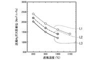
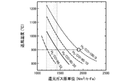
- FIG. 2 shows the relationship between the blowing temperature (° C.) of the mixed gas 30 and the hydrogen gas intensity (Nm 3 / t—Fe) for each addition amount of the nitrogen gas 32.
- Graph L1 shows the above relationship when nitrogen gas is not added
- graph L2 shows the above relationship when nitrogen gas is added to the reducing gas 31 at 250 Nm 3 / t-Fe
- graph L3 shows the relationship where nitrogen gas is added to the reduced gas 31 at 500 Nm 3.
- the above relationship when / t-Fe is added is shown. Therefore, the graphs L2 and L3 correspond to the shaft furnace operation according to the first embodiment. Since the hydrogen gas concentration of the reducing gas 31 is 100% by volume here, the hydrogen gas basic unit can be read as the reduced gas basic unit.
- the blowing temperatures of these graphs are 800 ° C., 840 ° C., 860 ° C., 880 ° C., 900 ° C., 920 ° C., 940 ° C., 960 ° C., 980 ° C., 1000 ° C., 1020 ° C., 1050 ° C., 1100 ° C. from the top. ing.
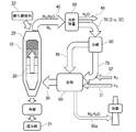
- the furnace top gas 40 is introduced into the separation / recovery device 60, and the top gas 40 is cooled in the separation / recovery device 60.
- the furnace top gas 40 is dust-removed.
- water vapor is removed from the furnace top gas 40 as water 65, and unreacted hydrogen gas 31a and nitrogen gas 32 are separated and recovered as circulating gas 70.
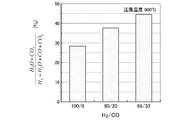
- the reducing gas 31 contains a reducing gas (CO or the like) other than hydrogen gas
- the circulating gas 70 may contain an oxide of the reducing gas (CO 2 or the like) in addition to the unreacted reducing gas.
- the circulating gas 70 contains these gases, there is no operational problem.
- the process flow of the method for producing reduced iron (shaft furnace operation) according to the second embodiment will be described with reference to FIG. 7.
- the second embodiment also contains the reducing gas 31 containing 90% by volume or more of hydrogen gas and the nitrogen gas 32, and blows the mixed gas 30 at a predetermined temperature into the shaft furnace 100. That is.
- the method for producing reduced iron according to the second embodiment is different from the first embodiment in that the reducing gas 31 and the nitrogen gas 32 are individually heated and then mixed.
- a step of individually heating the reducing gas 31 and the nitrogen gas 32 and a mixing of the heated reduced gas 31 and the nitrogen gas 32 are performed.
- the steps other than these may be the same as those of the existing shaft furnace operation.
- the heated reduction gas 31 and the nitrogen gas 32 are mixed in the mixing section 55 (for example, the confluence portion between the piping of the reduction gas 31 and the piping of the nitrogen gas 32). That is, the heated nitrogen gas 32 is added to the heated reducing gas 31. As a result, the mixed gas 30 having a predetermined temperature is produced. Then, the mixed gas 30 is blown into the shaft furnace 10. Subsequent steps are the same as in the first embodiment. Therefore, the heating temperature of the reducing gas 31 and the nitrogen gas 32 is adjusted so that the temperature of the mixed gas 30 after mixing becomes a predetermined temperature.
- the predetermined temperature is preferably 900 ° C. or lower as described above.
- the lower limit of the predetermined temperature is not particularly limited as long as the shaft furnace can be operated according to the second embodiment, but may be, for example, about 750 ° C.
- the amount of nitrogen gas 32 added is set to 330 Nm 3 / t-Fe to generate a hydrogen gas source.
- the blowing temperature of the mixed gas 30 can be reduced to 900 ° C. without increasing the unit (point P2).
- the reducing gas 31 and the nitrogen gas 32 are individually heated, and the heating temperature of the nitrogen gas 32 is raised to about 1350 ° C. to raise the heating temperature of the reducing gas 31 to about 800 ° C. It can be reduced (point P3).
Landscapes
- Engineering & Computer Science (AREA)
- Chemical & Material Sciences (AREA)
- Manufacturing & Machinery (AREA)
- Materials Engineering (AREA)
- Metallurgy (AREA)
- Organic Chemistry (AREA)
- General Engineering & Computer Science (AREA)
- Mechanical Engineering (AREA)
- Environmental & Geological Engineering (AREA)
- Manufacture Of Iron (AREA)
- Furnace Details (AREA)
- Manufacture And Refinement Of Metals (AREA)
- Compounds Of Iron (AREA)
- Waste-Gas Treatment And Other Accessory Devices For Furnaces (AREA)
- Control And Safety Of Cranes (AREA)
Abstract
Description
本願は、2020年5月14日に、日本に出願された特願2020-85078号に基づき優先権を主張し、その内容をここに援用する。

Fe2O3+3H2→2Fe+3H2O -854MJ/t-Fe ・・・・・(1)
Fe2O3+3CO→2Fe+3CO2 +246MJ/t-Fe ・・・・(2)
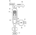
まず、図1に基づいて第1の実施形態に係る還元鉄の製造方法(シャフト炉操業)のプロセスフローを説明する。第1の実施形態は、概略的には、水素ガスを90体積%以上含有する還元ガス31と窒素ガス32とを含み、かつ加熱された混合ガス30をシャフト炉10に吹き込む、というものである。
つぎに、図5に基づいて第1の実施形態の第1の変形例を説明する。実際のシャフト炉操業では、還元ガス31及び窒素ガス32を有効利用することも重要である。そこで、第1の変形例では、炉頂ガス40から未反応の水素ガス31a及び窒素ガス32を分離回収し、混合ガス30の一部として再利用する。
つぎに、図6に基づいて第1の実施形態の第2の変形例を説明する。第2の変形例も第1の変形例と同様に炉頂ガス40から未反応の水素ガス31a及び窒素ガス32を分離回収し、混合ガス30の一部として再利用する。第2の変形例では、第1の変形例と同様の処理を行うほか、循環系内を循環する窒素ガス32の量を調整することができる。
つぎに、図7に基づいて第2の実施形態に係る還元鉄の製造方法(シャフト炉操業)のプロセスフローを説明する。第2の実施形態も、第1の実施形態と同様に、水素ガスを90体積%以上含有する還元ガス31と窒素ガス32とを含み、かつ所定温度の混合ガス30をシャフト炉100に吹き込む、というものである。ただし、第2の実施形態に係る還元鉄の製造方法は、還元ガス31と窒素ガス32とを個別に加熱した後に混合するという点で第1の実施形態と異なる。
つぎに、図9に基づいて第2の実施形態の変形例を説明する。本変形例は、概略的には、第1の実施形態の第1の変形例を第2の実施形態に適用したものである。つまり、本変形例では、炉頂ガス40から未反応の水素ガス31a及び窒素ガス32を個別に分離回収し、加熱対象の還元ガス31及び窒素ガス32として再利用する。
20 酸化鉄原料
30 混合ガス
31 還元ガス
32 窒素ガス
40 炉頂ガス
50 加熱炉
60 分離回収装置
70 循環ガス
80 分岐管
85 燃料用ガス
Claims (9)
- シャフト炉に装入された酸化鉄を還元することで還元鉄を製造する還元鉄の製造方法であって、
水素ガスを90体積%以上含有する還元ガスと窒素ガスとを含み、かつ加熱された混合ガスを前記シャフト炉に吹き込むことを特徴とする還元鉄の製造方法。 - シャフト炉に装入された酸化鉄を還元することで還元鉄を製造する還元鉄の製造方法であって、
水素ガスを90体積%以上含有する還元ガスと窒素ガスとを含む混合ガスを加熱する工程と、
前記加熱された混合ガスをシャフト炉に吹き込む工程と、を含むことを特徴とする、還元鉄の製造方法。 - 前記シャフト炉の炉頂ガスから少なくとも未反応の前記水素ガス及び前記窒素ガスを分離回収する工程と、
分離回収された前記水素ガス及び前記窒素ガスを前記混合ガスの一部として再使用する工程と、を含むことを特徴とする、請求項2に記載の還元鉄の製造方法。 - 分離回収された前記水素ガス及び前記窒素ガスの一部を、前記混合ガスを加熱する際の燃料用ガスとして使用することを特徴とする、請求項3に記載の還元鉄の製造方法。
- シャフト炉に装入された酸化鉄を還元することで還元鉄を製造する還元鉄の製造方法であって、
水素ガスを90体積%以上含有する還元ガスと窒素ガスとを個別に加熱する工程と、
加熱された前記還元ガスと前記窒素ガスとを混合することで、混合ガスを作製する工程と、
前記混合ガスをシャフト炉に吹き込む工程と、を含むことを特徴とする、還元鉄の製造方法。 - 前記窒素ガスの加熱温度を前記還元ガスの加熱温度よりも高くすることを特徴とする、請求項5記載の還元鉄の製造方法。
- 前記シャフト炉の炉頂ガスから少なくとも未反応の前記水素ガス及び前記窒素ガスを個別に分離回収する工程と、
分離回収された前記水素ガス及び前記窒素ガスを加熱対象の前記還元ガス及び前記窒素ガスとして再使用する工程と、を含むことを特徴とする、請求項5または6に記載の還元鉄の製造方法。 - 前記混合ガスは、前記窒素ガスを前記還元ガスの90体積%以下の割合で含有することを特徴とする、請求項1~7の何れか1項に記載の還元鉄の製造方法。
- 前記シャフト炉に吹き込まれる際の前記混合ガスの温度は900℃以下であることを特徴とする、請求項1~8の何れか1項に記載の還元鉄の製造方法。
Priority Applications (10)
| Application Number | Priority Date | Filing Date | Title |
|---|---|---|---|
| EP21804039.2A EP4151754A4 (en) | 2020-05-14 | 2021-05-13 | PROCESS FOR PRODUCING REDUCED IRON |
| MX2022014023A MX2022014023A (es) | 2020-05-14 | 2021-05-13 | Metodo para producir hierro reducido. |
| CA3176131A CA3176131A1 (en) | 2020-05-14 | 2021-05-13 | Method for producing reduced iron |
| KR1020227038898A KR20220160694A (ko) | 2020-05-14 | 2021-05-13 | 환원철의 제조 방법 |
| BR112022021572A BR112022021572A2 (pt) | 2020-05-14 | 2021-05-13 | Método para produzir ferro reduzido |
| CN202180034277.4A CN115552041A (zh) | 2020-05-14 | 2021-05-13 | 还原铁的制造方法 |
| JP2022522188A JP7575697B2 (ja) | 2020-05-14 | 2021-05-13 | 還元鉄の製造方法 |
| AU2021272824A AU2021272824B2 (en) | 2020-05-14 | 2021-05-13 | Method for producing reduced iron |
| US17/921,654 US12486548B2 (en) | 2020-05-14 | 2021-05-13 | Method for producing reduced iron |
| JP2024091753A JP2024113093A (ja) | 2020-05-14 | 2024-06-05 | 還元鉄の製造方法 |
Applications Claiming Priority (2)
| Application Number | Priority Date | Filing Date | Title |
|---|---|---|---|
| JP2020085078 | 2020-05-14 | ||
| JP2020-085078 | 2020-05-14 |
Publications (1)
| Publication Number | Publication Date |
|---|---|
| WO2021230307A1 true WO2021230307A1 (ja) | 2021-11-18 |
Family
ID=78524497
Family Applications (1)
| Application Number | Title | Priority Date | Filing Date |
|---|---|---|---|
| PCT/JP2021/018156 Ceased WO2021230307A1 (ja) | 2020-05-14 | 2021-05-13 | 還元鉄の製造方法 |
Country Status (11)
| Country | Link |
|---|---|
| US (1) | US12486548B2 (ja) |
| EP (1) | EP4151754A4 (ja) |
| JP (2) | JP7575697B2 (ja) |
| KR (1) | KR20220160694A (ja) |
| CN (1) | CN115552041A (ja) |
| AU (1) | AU2021272824B2 (ja) |
| BR (1) | BR112022021572A2 (ja) |
| CA (1) | CA3176131A1 (ja) |
| MX (1) | MX2022014023A (ja) |
| TW (1) | TWI788843B (ja) |
| WO (1) | WO2021230307A1 (ja) |
Cited By (5)
| Publication number | Priority date | Publication date | Assignee | Title |
|---|---|---|---|---|
| SE2250610A1 (en) * | 2022-05-20 | 2023-11-21 | Greeniron H2 Ab | Method and device for producing direct reduced metal |
| WO2024018692A1 (ja) | 2022-07-21 | 2024-01-25 | 住友金属鉱山株式会社 | 含ニッケル酸化鉱石の製錬方法 |
| WO2025028432A1 (ja) | 2023-07-28 | 2025-02-06 | 住友金属鉱山株式会社 | 含ニッケル酸化鉱石の製錬方法 |
| EP4288571B1 (en) | 2021-02-03 | 2025-06-18 | HYBRIT Development AB | Bleed-off gas recovery in a direct reduction process |
| WO2025158579A1 (ja) * | 2024-01-24 | 2025-07-31 | 日本製鉄株式会社 | 還元鉄の製造方法及びシャフト炉 |
Families Citing this family (1)
| Publication number | Priority date | Publication date | Assignee | Title |
|---|---|---|---|---|
| CN116734616A (zh) * | 2023-06-02 | 2023-09-12 | 东北大学 | 一种氢基竖炉炉顶煤气的膜法回收利用装置及方法 |
Citations (12)
| Publication number | Priority date | Publication date | Assignee | Title |
|---|---|---|---|---|
| US2862808A (en) | 1957-07-31 | 1958-12-02 | Alan N Mann | Apparatus and method for reducing iron oxide pellets |
| JPS4947208A (ja) * | 1972-03-11 | 1974-05-07 | ||
| DE2422641A1 (de) | 1973-05-18 | 1974-12-05 | Centre Rech Metallurgique | Verfahren zur erzreduktion |
| US4363654A (en) * | 1980-04-08 | 1982-12-14 | Geoffrey Frederick | Production of reducing gas for furnace injection |
| JPS63171817A (ja) | 1987-01-09 | 1988-07-15 | Nkk Corp | 高炉付帯設備 |
| US6027545A (en) | 1998-02-20 | 2000-02-22 | Hylsa, S.A. De C.V. | Method and apparatus for producing direct reduced iron with improved reducing gas utilization |
| CN101787406A (zh) * | 2010-01-12 | 2010-07-28 | 北京科技大学 | 一种超细赤铁矿粉非熔态还原工艺及装置 |
| KR20120075201A (ko) * | 2010-12-28 | 2012-07-06 | 주식회사 포스코 | 환원철의 제조방법 및 제조장치 |
| CN105219907A (zh) | 2015-10-14 | 2016-01-06 | 钢铁研究总院 | 高磷鲕状赤铁矿气基直接还原-磨矿磁选的炼铁工艺 |
| US20170239700A1 (en) | 2016-02-23 | 2017-08-24 | Bilstein Gmbh & Co. Kg | Method of and apparatus for rolling strip of fluctuating thickness |
| CA3103187A1 (en) | 2018-06-12 | 2019-12-19 | Primetals Technologies Austria GmbH | Method for carburization of hdri produced in h2 based direct reduction process |
| JP2020085078A (ja) | 2018-11-20 | 2020-06-04 | Kyb株式会社 | 流体圧制御装置 |
Family Cites Families (8)
| Publication number | Priority date | Publication date | Assignee | Title |
|---|---|---|---|---|
| US2609288A (en) | 1949-03-08 | 1952-09-02 | Isobel E Stuart | Process for the reduction of metal oxides by gases |
| GB729146A (en) * | 1952-06-18 | 1955-05-04 | Stanley Edward Matthews | Apparatus and process for the reduction of metal oxides by gases |
| US3135598A (en) * | 1960-04-27 | 1964-06-02 | Yawata Iron & Steel Co | Rapid direct reduction method of iron oxide |
| AU543499B2 (en) * | 1979-04-24 | 1985-04-26 | Foster Wheeler Ltd. | Producing hydrogen and injecting into direct reduction furnaces or blast furnaces |
| ZA802257B (en) | 1979-04-24 | 1982-02-24 | Foster Wheeler Ltd | Production of reducing gas for furnace injection |
| JP6152221B2 (ja) | 2013-07-31 | 2017-06-21 | ミドレックス テクノロジーズ,インコーポレイテッド | 天然ガスを用いた酸化鉄の金属鉄への還元 |
| UA117374C2 (uk) * | 2013-07-31 | 2018-07-25 | Мідрекс Текнолоджиз, Інк. | Відновлення оксиду заліза до металевого заліза із застосуванням коксового газу та газу зі сталеплавильної печі з подачею кисню |
| JP5714750B1 (ja) * | 2014-06-02 | 2015-05-07 | 新日鉄住金エンジニアリング株式会社 | 直接還元鉄の製造設備、及び直接還元鉄の製造方法 |
-
2021
- 2021-05-13 WO PCT/JP2021/018156 patent/WO2021230307A1/ja not_active Ceased
- 2021-05-13 US US17/921,654 patent/US12486548B2/en active Active
- 2021-05-13 KR KR1020227038898A patent/KR20220160694A/ko not_active Ceased
- 2021-05-13 AU AU2021272824A patent/AU2021272824B2/en active Active
- 2021-05-13 MX MX2022014023A patent/MX2022014023A/es unknown
- 2021-05-13 TW TW110117325A patent/TWI788843B/zh active
- 2021-05-13 EP EP21804039.2A patent/EP4151754A4/en active Pending
- 2021-05-13 CN CN202180034277.4A patent/CN115552041A/zh active Pending
- 2021-05-13 JP JP2022522188A patent/JP7575697B2/ja active Active
- 2021-05-13 CA CA3176131A patent/CA3176131A1/en active Pending
- 2021-05-13 BR BR112022021572A patent/BR112022021572A2/pt not_active Application Discontinuation
-
2024
- 2024-06-05 JP JP2024091753A patent/JP2024113093A/ja active Pending
Patent Citations (13)
| Publication number | Priority date | Publication date | Assignee | Title |
|---|---|---|---|---|
| US2862808A (en) | 1957-07-31 | 1958-12-02 | Alan N Mann | Apparatus and method for reducing iron oxide pellets |
| JPS4947208A (ja) * | 1972-03-11 | 1974-05-07 | ||
| DE2422641A1 (de) | 1973-05-18 | 1974-12-05 | Centre Rech Metallurgique | Verfahren zur erzreduktion |
| US4363654A (en) * | 1980-04-08 | 1982-12-14 | Geoffrey Frederick | Production of reducing gas for furnace injection |
| JPS63171817A (ja) | 1987-01-09 | 1988-07-15 | Nkk Corp | 高炉付帯設備 |
| US6027545A (en) | 1998-02-20 | 2000-02-22 | Hylsa, S.A. De C.V. | Method and apparatus for producing direct reduced iron with improved reducing gas utilization |
| CN101787406A (zh) * | 2010-01-12 | 2010-07-28 | 北京科技大学 | 一种超细赤铁矿粉非熔态还原工艺及装置 |
| KR20120075201A (ko) * | 2010-12-28 | 2012-07-06 | 주식회사 포스코 | 환원철의 제조방법 및 제조장치 |
| CN105219907A (zh) | 2015-10-14 | 2016-01-06 | 钢铁研究总院 | 高磷鲕状赤铁矿气基直接还原-磨矿磁选的炼铁工艺 |
| US20170239700A1 (en) | 2016-02-23 | 2017-08-24 | Bilstein Gmbh & Co. Kg | Method of and apparatus for rolling strip of fluctuating thickness |
| CA3103187A1 (en) | 2018-06-12 | 2019-12-19 | Primetals Technologies Austria GmbH | Method for carburization of hdri produced in h2 based direct reduction process |
| WO2019238720A1 (de) | 2018-06-12 | 2019-12-19 | Primetals Technologies Austria GmbH | Herstellung von karburiertem eisenschwamm mittels wasserstoffbasierter direktreduktion |
| JP2020085078A (ja) | 2018-11-20 | 2020-06-04 | Kyb株式会社 | 流体圧制御装置 |
Non-Patent Citations (7)
| Title |
|---|
| ANONYMOUS: "Program of the Conference ''METEC & 4th ESTAD 2019", WWW.METEC-ESTAD2019.COM, 1 January 2019 (2019-01-01), pages 1 - 96, XP093177874, Retrieved from the Internet <URL:www.metec-estad2019.com> |
| CHEVRIER V.: "MIDREX H2 Ultra Low CO2 Ironmaking in the transition to the Hydrogen Economy", MIDREX, 27 June 2019 (2019-06-27), pages 1 - 7, XP093177868 |
| HARA ET AL., TETSU-TO-HAGANE, vol. 62, 1976, pages 315 |
| HARUNA, KAZUO ET AL.: "Gas Separation by Pressure Swing Adsorption", JOURNAL OF THE VACUUM SOCIETY OF JAPAN, vol. 43, no. 12, 20 December 2000 (2000-12-20), pages 1088 - 1093, XP009537906, ISSN: 1882-2398, DOI: 10.3131/jvsj.43.1088 |
| MIDREX TECHNOLOGIES: "Midrex Technologies_DIRECT FROM MIDREX - 3rd QUARTER 2017", WWW.MIDREX.COM, 1 January 2017 (2017-01-01), pages 1 - 15, XP093177856, Retrieved from the Internet <URL:https://www.midrex.com/wp-content/uploads/Midrex_2017_DFM3QTR_FinalPrint.pdf> |
| See also references of EP4151754A1 |
| YAMAOKA ET AL., TETSU-TO-HAGANE, vol. 74, 1988, pages 2254 |
Cited By (9)
| Publication number | Priority date | Publication date | Assignee | Title |
|---|---|---|---|---|
| EP4288571B1 (en) | 2021-02-03 | 2025-06-18 | HYBRIT Development AB | Bleed-off gas recovery in a direct reduction process |
| SE2250610A1 (en) * | 2022-05-20 | 2023-11-21 | Greeniron H2 Ab | Method and device for producing direct reduced metal |
| WO2023224541A1 (en) * | 2022-05-20 | 2023-11-23 | Greeniron H2 Ab | Method and device for producing direct reduced metal |
| SE545792C2 (en) * | 2022-05-20 | 2024-02-06 | Greeniron H2 Ab | Method and device for producing direct reduced metal |
| WO2024018692A1 (ja) | 2022-07-21 | 2024-01-25 | 住友金属鉱山株式会社 | 含ニッケル酸化鉱石の製錬方法 |
| KR20250025468A (ko) | 2022-07-21 | 2025-02-21 | 스미토모 긴조쿠 고잔 가부시키가이샤 | 니켈 함유 산화광석의 제련 방법 |
| WO2025028432A1 (ja) | 2023-07-28 | 2025-02-06 | 住友金属鉱山株式会社 | 含ニッケル酸化鉱石の製錬方法 |
| WO2025158579A1 (ja) * | 2024-01-24 | 2025-07-31 | 日本製鉄株式会社 | 還元鉄の製造方法及びシャフト炉 |
| JP7737064B1 (ja) * | 2024-01-24 | 2025-09-10 | 日本製鉄株式会社 | 還元鉄の製造方法及びシャフト炉 |
Also Published As
| Publication number | Publication date |
|---|---|
| TW202146667A (zh) | 2021-12-16 |
| JP2024113093A (ja) | 2024-08-21 |
| US12486548B2 (en) | 2025-12-02 |
| CN115552041A (zh) | 2022-12-30 |
| EP4151754A4 (en) | 2023-09-13 |
| MX2022014023A (es) | 2022-11-30 |
| EP4151754A1 (en) | 2023-03-22 |
| TWI788843B (zh) | 2023-01-01 |
| BR112022021572A2 (pt) | 2022-12-06 |
| US20230167516A1 (en) | 2023-06-01 |
| JPWO2021230307A1 (ja) | 2021-11-18 |
| AU2021272824A1 (en) | 2022-11-24 |
| AU2021272824B2 (en) | 2024-10-03 |
| JP7575697B2 (ja) | 2024-10-30 |
| KR20220160694A (ko) | 2022-12-06 |
| CA3176131A1 (en) | 2021-11-18 |
Similar Documents
| Publication | Publication Date | Title |
|---|---|---|
| WO2021230307A1 (ja) | 還元鉄の製造方法 | |
| WO2021241272A1 (ja) | 還元鉄の製造方法 | |
| RU2679817C2 (ru) | Способ эксплуатации доменной печи | |
| CN113423845B (zh) | 高炉操作方法 | |
| CN115011746B (zh) | 一种基于co2循环的全氧/高富氧炼铁造气系统及运行方法 | |
| WO2011087036A1 (ja) | 製鉄方法 | |
| EP4350011A1 (en) | Method for producing reduced iron | |
| EP4353841A1 (en) | Shaft furnace operation method and reduce iron production method | |
| JP7272517B1 (ja) | 還元鉄の製造方法 | |
| CN117545858A (zh) | 直接还原过程中的氢气再循环 | |
| CN116203901A (zh) | 一种稳定碳循环的高炉生产控制方法、系统、电子设备及存储介质 | |
| JP7055082B2 (ja) | 高炉の操業方法 | |
| WO2024135697A1 (ja) | 還元鉄の製造方法 | |
| KR102548309B1 (ko) | 이산화탄소 배출 저감형 용철 제조장치 및 그 제조방법 | |
| JP7719423B1 (ja) | 還元鉄の製造方法及び還元鉄の製造装置 | |
| JP2016513004A (ja) | 二酸化炭素を使用済みガスから分離する方法、及び装置 | |
| JP2026052010A (ja) | 高炉ガスの調整方法、水素の回収方法及び二酸化炭素の気体源の回収方法 | |
| WO2025187531A1 (ja) | 高炉の操業方法 | |
| WO2025134546A1 (ja) | 還元鉄の製造方法 | |
| CN121272136A (zh) | 基于气体组分调控的化学自热还原冶金方法 | |
| KR20010003726A (ko) | 용융로의 로열관리방법 | |
| JP2004204292A (ja) | アイアンカーバイドを用いた水素及び鉄の製造方法並びに装置 |
Legal Events
| Date | Code | Title | Description |
|---|---|---|---|
| 121 | Ep: the epo has been informed by wipo that ep was designated in this application |
Ref document number: 21804039 Country of ref document: EP Kind code of ref document: A1 |
|
| ENP | Entry into the national phase |
Ref document number: 2022522188 Country of ref document: JP Kind code of ref document: A |
|
| ENP | Entry into the national phase |
Ref document number: 3176131 Country of ref document: CA |
|
| WWE | Wipo information: entry into national phase |
Ref document number: 202217061608 Country of ref document: IN |
|
| REG | Reference to national code |
Ref country code: BR Ref legal event code: B01A Ref document number: 112022021572 Country of ref document: BR |
|
| ENP | Entry into the national phase |
Ref document number: 20227038898 Country of ref document: KR Kind code of ref document: A |
|
| ENP | Entry into the national phase |
Ref document number: 2021272824 Country of ref document: AU Date of ref document: 20210513 Kind code of ref document: A |
|
| ENP | Entry into the national phase |
Ref document number: 112022021572 Country of ref document: BR Kind code of ref document: A2 Effective date: 20221024 |
|
| NENP | Non-entry into the national phase |
Ref country code: DE |
|
| ENP | Entry into the national phase |
Ref document number: 2021804039 Country of ref document: EP Effective date: 20221214 |