WO2021240729A1 - 冷凍サイクル装置 - Google Patents
冷凍サイクル装置 Download PDFInfo
- Publication number
- WO2021240729A1 WO2021240729A1 PCT/JP2020/021141 JP2020021141W WO2021240729A1 WO 2021240729 A1 WO2021240729 A1 WO 2021240729A1 JP 2020021141 W JP2020021141 W JP 2020021141W WO 2021240729 A1 WO2021240729 A1 WO 2021240729A1
- Authority
- WO
- WIPO (PCT)
- Prior art keywords
- heat medium
- heat exchanger
- load device
- bypass valve
- passage
- Prior art date
- Legal status (The legal status is an assumption and is not a legal conclusion. Google has not performed a legal analysis and makes no representation as to the accuracy of the status listed.)
- Ceased
Links
Images


Classifications
-
- F—MECHANICAL ENGINEERING; LIGHTING; HEATING; WEAPONS; BLASTING
- F24—HEATING; RANGES; VENTILATING
- F24F—AIR-CONDITIONING; AIR-HUMIDIFICATION; VENTILATION; USE OF AIR CURRENTS FOR SCREENING
- F24F5/00—Air-conditioning systems or apparatus not covered by F24F1/00 or F24F3/00, e.g. using solar heat or combined with household units such as an oven or water heater
- F24F5/0007—Air-conditioning systems or apparatus not covered by F24F1/00 or F24F3/00, e.g. using solar heat or combined with household units such as an oven or water heater cooling apparatus specially adapted for use in air-conditioning
- F24F5/001—Compression cycle type
-
- F—MECHANICAL ENGINEERING; LIGHTING; HEATING; WEAPONS; BLASTING
- F24—HEATING; RANGES; VENTILATING
- F24F—AIR-CONDITIONING; AIR-HUMIDIFICATION; VENTILATION; USE OF AIR CURRENTS FOR SCREENING
- F24F11/00—Control or safety arrangements
- F24F11/70—Control systems characterised by their outputs; Constructional details thereof
- F24F11/80—Control systems characterised by their outputs; Constructional details thereof for controlling the temperature of the supplied air
- F24F11/83—Control systems characterised by their outputs; Constructional details thereof for controlling the temperature of the supplied air by controlling the supply of heat-exchange fluids to heat-exchangers
- F24F11/84—Control systems characterised by their outputs; Constructional details thereof for controlling the temperature of the supplied air by controlling the supply of heat-exchange fluids to heat-exchangers using valves
-
- F—MECHANICAL ENGINEERING; LIGHTING; HEATING; WEAPONS; BLASTING
- F24—HEATING; RANGES; VENTILATING
- F24F—AIR-CONDITIONING; AIR-HUMIDIFICATION; VENTILATION; USE OF AIR CURRENTS FOR SCREENING
- F24F11/00—Control or safety arrangements
- F24F11/62—Control or safety arrangements characterised by the type of control or by internal processing, e.g. using fuzzy logic, adaptive control or estimation of values
- F24F11/63—Electronic processing
- F24F11/65—Electronic processing for selecting an operating mode
-
- F—MECHANICAL ENGINEERING; LIGHTING; HEATING; WEAPONS; BLASTING
- F25—REFRIGERATION OR COOLING; COMBINED HEATING AND REFRIGERATION SYSTEMS; HEAT PUMP SYSTEMS; MANUFACTURE OR STORAGE OF ICE; LIQUEFACTION SOLIDIFICATION OF GASES
- F25B—REFRIGERATION MACHINES, PLANTS OR SYSTEMS; COMBINED HEATING AND REFRIGERATION SYSTEMS; HEAT PUMP SYSTEMS
- F25B13/00—Compression machines, plants or systems, with reversible cycle
-
- F—MECHANICAL ENGINEERING; LIGHTING; HEATING; WEAPONS; BLASTING
- F25—REFRIGERATION OR COOLING; COMBINED HEATING AND REFRIGERATION SYSTEMS; HEAT PUMP SYSTEMS; MANUFACTURE OR STORAGE OF ICE; LIQUEFACTION SOLIDIFICATION OF GASES
- F25B—REFRIGERATION MACHINES, PLANTS OR SYSTEMS; COMBINED HEATING AND REFRIGERATION SYSTEMS; HEAT PUMP SYSTEMS
- F25B25/00—Machines, plants or systems, using a combination of modes of operation covered by two or more of the groups F25B1/00 - F25B23/00
- F25B25/005—Machines, plants or systems, using a combination of modes of operation covered by two or more of the groups F25B1/00 - F25B23/00 using primary and secondary systems
-
- F—MECHANICAL ENGINEERING; LIGHTING; HEATING; WEAPONS; BLASTING
- F25—REFRIGERATION OR COOLING; COMBINED HEATING AND REFRIGERATION SYSTEMS; HEAT PUMP SYSTEMS; MANUFACTURE OR STORAGE OF ICE; LIQUEFACTION SOLIDIFICATION OF GASES
- F25B—REFRIGERATION MACHINES, PLANTS OR SYSTEMS; COMBINED HEATING AND REFRIGERATION SYSTEMS; HEAT PUMP SYSTEMS
- F25B41/00—Fluid-circulation arrangements
- F25B41/20—Disposition of valves, e.g. of on-off valves or flow control valves
-
- F—MECHANICAL ENGINEERING; LIGHTING; HEATING; WEAPONS; BLASTING
- F25—REFRIGERATION OR COOLING; COMBINED HEATING AND REFRIGERATION SYSTEMS; HEAT PUMP SYSTEMS; MANUFACTURE OR STORAGE OF ICE; LIQUEFACTION SOLIDIFICATION OF GASES
- F25B—REFRIGERATION MACHINES, PLANTS OR SYSTEMS; COMBINED HEATING AND REFRIGERATION SYSTEMS; HEAT PUMP SYSTEMS
- F25B49/00—Arrangement or mounting of control or safety devices
- F25B49/02—Arrangement or mounting of control or safety devices for compression type machines, plants or systems
-
- F—MECHANICAL ENGINEERING; LIGHTING; HEATING; WEAPONS; BLASTING
- F24—HEATING; RANGES; VENTILATING
- F24F—AIR-CONDITIONING; AIR-HUMIDIFICATION; VENTILATION; USE OF AIR CURRENTS FOR SCREENING
- F24F2110/00—Control inputs relating to air properties
- F24F2110/10—Temperature
- F24F2110/12—Temperature of the outside air
-
- F—MECHANICAL ENGINEERING; LIGHTING; HEATING; WEAPONS; BLASTING
- F24—HEATING; RANGES; VENTILATING
- F24F—AIR-CONDITIONING; AIR-HUMIDIFICATION; VENTILATION; USE OF AIR CURRENTS FOR SCREENING
- F24F2140/00—Control inputs relating to system states
- F24F2140/20—Heat-exchange fluid temperature
-
- F—MECHANICAL ENGINEERING; LIGHTING; HEATING; WEAPONS; BLASTING
- F25—REFRIGERATION OR COOLING; COMBINED HEATING AND REFRIGERATION SYSTEMS; HEAT PUMP SYSTEMS; MANUFACTURE OR STORAGE OF ICE; LIQUEFACTION SOLIDIFICATION OF GASES
- F25B—REFRIGERATION MACHINES, PLANTS OR SYSTEMS; COMBINED HEATING AND REFRIGERATION SYSTEMS; HEAT PUMP SYSTEMS
- F25B2313/00—Compression machines, plants or systems with reversible cycle not otherwise provided for
- F25B2313/003—Indoor unit with water as a heat sink or heat source
-
- F—MECHANICAL ENGINEERING; LIGHTING; HEATING; WEAPONS; BLASTING
- F25—REFRIGERATION OR COOLING; COMBINED HEATING AND REFRIGERATION SYSTEMS; HEAT PUMP SYSTEMS; MANUFACTURE OR STORAGE OF ICE; LIQUEFACTION SOLIDIFICATION OF GASES
- F25B—REFRIGERATION MACHINES, PLANTS OR SYSTEMS; COMBINED HEATING AND REFRIGERATION SYSTEMS; HEAT PUMP SYSTEMS
- F25B2313/00—Compression machines, plants or systems with reversible cycle not otherwise provided for
- F25B2313/027—Compression machines, plants or systems with reversible cycle not otherwise provided for characterised by the reversing means
- F25B2313/02741—Compression machines, plants or systems with reversible cycle not otherwise provided for characterised by the reversing means using one four-way valve
-
- Y—GENERAL TAGGING OF NEW TECHNOLOGICAL DEVELOPMENTS; GENERAL TAGGING OF CROSS-SECTIONAL TECHNOLOGIES SPANNING OVER SEVERAL SECTIONS OF THE IPC; TECHNICAL SUBJECTS COVERED BY FORMER USPC CROSS-REFERENCE ART COLLECTIONS [XRACs] AND DIGESTS
- Y02—TECHNOLOGIES OR APPLICATIONS FOR MITIGATION OR ADAPTATION AGAINST CLIMATE CHANGE
- Y02B—CLIMATE CHANGE MITIGATION TECHNOLOGIES RELATED TO BUILDINGS, e.g. HOUSING, HOUSE APPLIANCES OR RELATED END-USER APPLICATIONS
- Y02B30/00—Energy efficient heating, ventilation or air conditioning [HVAC]
- Y02B30/54—Free-cooling systems
Definitions
- This disclosure relates to a refrigeration cycle device.
- Patent Document 1 discloses an air-conditioning operation method using free cooling.
- a low-temperature cold water tank and a high-temperature cold water tank are provided. Is supplied to a high-temperature cold water tank for microheat treatment.
- the low-temperature cold water produced by the refrigerator or the low-temperature cold water produced by the cooling tower is used to produce the high-temperature cold water in the high-temperature cold water tank.
- the above-mentioned conventional technique requires two water tanks and two pumps for sending water between each water tank and the load, so that there is a problem that the cost is high.
- the present disclosure has been made to solve the above-mentioned problems, and an object of the present disclosure is to provide a refrigeration cycle device having a simple configuration and advantageous in increasing opportunities to utilize free cooling.
- the refrigeration cycle apparatus of the present disclosure includes a compressor that compresses the refrigerant, a first heat exchanger that cools the refrigerant compressed by the compressor with outdoor air, a decompression device that reduces the pressure of the refrigerant, and a decompression device.
- the second heat exchanger that cools the heat medium with the generated refrigerant, the third heat exchanger that cools the heat medium with the outdoor air, and the heat medium outlet of the third heat exchanger are the heat medium inlets of the second heat exchanger.
- the first heat medium passage connected to the first heat medium passage, the first bypass valve for flowing the heat medium from the first heat medium passage into the first load device, and the second heat medium flowing out from the second heat exchanger to flow into the second load device.
- Two heat medium passages Two heat medium passages, a second bypass valve that allows the heat medium flowing out of the second heat exchanger to flow into the first load device, a heat medium returned from the first load device, and a heat medium returned from the second load device.
- FIG. 1 It is a figure which shows the refrigeration cycle apparatus by Embodiment 1.
- FIG. 2 It is a figure which shows the state which the refrigerating cycle apparatus is operating in the free cooling combined operation mode. It is a figure which shows the refrigeration cycle apparatus by Embodiment 2.
- FIG. 2 It is a figure which shows the refrigeration cycle apparatus by Embodiment 3.
- FIG. 1 It is a figure which shows the refrigeration cycle apparatus by Embodiment 1.
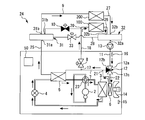
- FIG. 1 is a diagram showing a refrigeration cycle device 1 according to the first embodiment.
- the refrigeration cycle device 1 reduces the pressure of the refrigerant, the compressor 2 that compresses the refrigerant, the first heat exchanger 3 that cools the refrigerant compressed by the compressor 2 with the outdoor air, and the refrigerant.
- a decompression device 4 a second heat exchanger 5 that cools the heat medium with the refrigerant decompressed by the decompression device 4, a third heat exchanger 6 that cools the heat medium with outdoor air, and a third heat exchanger 6.
- the first heat medium passage 7 connecting the heat medium outlet to the heat medium inlet of the second heat exchanger 5, the first bypass valve 8 for flowing the heat medium from the first heat medium passage 7 into the first load device 100, and the first.
- a second heat medium passage 9 that allows the heat medium flowing out of the second heat exchanger 5 to flow into the second load device 200, and a second bypass that causes the heat medium flowing out of the second heat exchanger 5 to flow into the first load device 100.
- the return passage 11 through which the valve 10, the heat medium returned from the first load device 100, and the heat medium returned from the second load device 200 pass, and the heat medium do not pass through the return passage 11 to the third heat exchanger 6.
- a flow path switching valve 12 for switching between a first mode in which the heat medium flows into the first heat medium passage 7 and a second mode in which the heat medium flows into the third heat exchanger 6 from the return passage 11 is provided.
- the substance used as the refrigerant in the present disclosure is not particularly limited , but may be, for example, CO 2 , HFC, HFO, or a hydrocarbon.
- the substance used as a heat medium in the present disclosure is typically liquid water.
- a liquid other than water such as an aqueous solution of calcium chloride, an aqueous solution of ethylene glycol, an aqueous solution of propylene glycol, or alcohol, may be used as a heat medium.
- a heat medium pump 13 for circulating the heat medium is provided in the return passage 11.
- the first heat exchanger 3 is configured to cool the heat medium by heat exchange using outdoor air.
- the first heat exchanger 3 may be configured to directly exchange heat between the outdoor air and the heat medium in a closed cooling tower.
- the first heat exchanger 3 may be configured to exchange heat between the cooling water cooled by the outdoor air and the heat medium in the open cooling tower.
- the third heat exchanger 6 is configured to cool the heat medium by heat exchange using outdoor air.
- the third heat exchanger 6 may be configured to directly exchange heat between the outdoor air and the heat medium in a closed cooling tower.
- the third heat exchanger 6 may be configured to exchange heat between the cooling water cooled by the outdoor air and the heat medium in the open cooling tower.
- the first heat exchanger 3 and the third heat exchanger 6 are arranged next to each other. Further, in the illustrated example, a blower 14 for sending outdoor air to the first heat exchanger 3 and the third heat exchanger 6 is provided. The blower 14 may be omitted. Instead of the illustrated example, the third heat exchanger 6 may be arranged at a place away from the first heat exchanger 3. In that case, a blower that sends outdoor air to the first heat exchanger 3 and a blower that sends outdoor air to the third heat exchanger 6 may be individually provided.
- first load device 100 and the second load device 200 are configured to perform air conditioning in the room by using a heat medium.
- the present disclosure is not limited to a system that performs air conditioning.
- either or both of the first load device 100 and the second load device 200 may be configured to cool the production device using a heat medium.
- the first load device 100 may have a heat exchanger that exchanges heat between the indoor air and the heat medium.
- the first load device 100 may be configured by, for example, a fan coil unit.
- the first load device 100 may be configured primarily to handle the sensible heat load in air conditioning. That is, the first load device 100 may be configured to lower the temperature of the indoor air.
- FIG. 1 shows a state in which the refrigerating cycle device 1 is operated in the chiller independent operation mode.
- the heat medium is cooled by operating the compressor 2 without performing free cooling by the third heat exchanger 6.
- the refrigeration cycle device 1 in the chiller independent operation mode operates as follows.
- the high-temperature and high-pressure refrigerant compressed by the compressor 2 flows into the first heat exchanger 3.
- the refrigerant cooled by the outdoor air in the first heat exchanger 3 is decompressed when passing through the decompression device 4.
- the first bypass valve 8 is closed.
- the second bypass valve 10 is open.
- the flow path switching valve 12 is in the first mode.
- the heat medium is cooled by exchanging heat between the low-temperature low-pressure refrigerant flowing out of the decompression device 4 and the heat medium.
- a part of the heat medium flowing out of the second heat exchanger 5 is supplied to the first load device 100 through the second bypass valve 10.
- the rest of the heat medium flowing out of the second heat exchanger 5 is supplied to the second load device 200 through the second heat medium passage 9.
- the heat medium returned from the first load device 100 and the heat medium returned from the second load device 200 merge and flow through the return passage 11.
- the heat medium flows from the return passage 11 into the first heat medium passage 7 without passing through the third heat exchanger 6.
- the entire amount of the heat medium that has flowed into the first heat medium passage 7 flows into the second heat exchanger 5.
- FIG. 2 is a diagram showing a state in which the refrigerating cycle device 1 is operated in the free cooling combined operation mode.
- the heat medium is cooled by using the free cooling by the third heat exchanger 6 and the operation of the compressor 2 in combination.
- the refrigerating cycle device 1 in the free cooling combined operation mode operates as follows.
- the refrigerant circulates through the same path as in the chiller independent operation mode.
- the first bypass valve 8 is open.
- the second bypass valve 10 is closed.
- the flow path switching valve 12 is in the second mode.
- the heat medium returned from the first load device 100 and the heat medium returned from the second load device 200 merge and flow through the return passage 11.
- the heat medium that has passed through the return passage 11 flows into the third heat exchanger 6.
- the heat medium cooled by the outdoor air in the third heat exchanger 6 flows into the first heat medium passage 7.
- a part of the heat medium flowing through the first heat medium passage 7 is supplied to the first load device 100 through the first bypass valve 8.
- the rest of the heat medium flowing through the first heat medium passage 7 flows into the second heat exchanger 5.
- the heat medium cooled by the refrigerant in the second heat exchanger 5 is supplied to the second load device 200 through the second heat medium passage 9.
- the temperature of the heat medium flowing from the second heat exchanger 5 to the second load device 200 needs to be lower than the dew point temperature.
- the power consumption of the compressor 2 when the heat medium is cooled to the same temperature increases as the flow rate of the heat medium flowing through the second heat exchanger 5 increases.
- the flow rate of the heat medium flowing through the second heat exchanger 5 in the free cooling combined operation mode is smaller than that in the chiller independent operation mode. Therefore, in the free cooling combined operation mode, the power consumption of the compressor 2 can be reduced and energy saving can be achieved as compared with the chiller independent operation mode.
- the heat medium cooled by the free cooling of the third heat exchanger 6 flows into the first load device 100.
- the temperature of the heat medium cooled by free cooling changes according to the outside air temperature.
- the temperature of the heat medium flowing into the first load device 100 that processes the sensible heat may be higher than the dew point temperature.
- the heat medium cooled by the free cooling can be supplied to the first load device 100, and the heat medium further cooled by the second heat exchanger 5 to a temperature lower than the dew point temperature can be supplied. It can be supplied to the second load device 200. Therefore, in the case of the refrigerating cycle apparatus 1 of the present embodiment, free cooling can be utilized even when the temperature of the heat medium cooled by free cooling is higher than the dew point temperature.
- the above effect can be achieved by the refrigerating cycle apparatus 1 having a simple structure, so that the product cost can be suppressed.
- a simple configuration is achieved by eliminating the need for a tank for separately storing the heat medium cooled by free cooling and the heat medium further cooled by the second heat exchanger 5.
- a simple configuration is achieved by circulating both the heat medium cooled by free cooling and the heat medium further cooled by the second heat exchanger 5 by the common heat medium pump 13. ..
- the second bypass valve 10 may be opened a little in the free cooling combined operation mode. As a result, the heat medium that has passed through the first bypass valve 8 is mixed with the heat medium that has passed through the second bypass valve 10, so that the temperature of the heat medium that flows into the first load device 100 can be lowered.
- the refrigeration cycle device 1 may further include a control circuit 50 configured to control the operation of the first bypass valve 8, the operation of the second bypass valve 10, and the operation of the flow path switching valve 12. ..
- a control circuit 50 configured to control the operation of the first bypass valve 8, the operation of the second bypass valve 10, and the operation of the flow path switching valve 12. ..
- the control circuit 50 may be configured to close the first bypass valve 8 and open the second bypass valve 10 when the flow path switching valve 12 is in the first mode. This makes it possible to automate the operation of the chiller independent operation mode.
- the control circuit 50 may be configured to perform a process of opening the first bypass valve 8 and a process of closing the second bypass valve 10 when the flow path switching valve 12 is in the second mode. Further, the control circuit 50 determines the process of opening the first bypass valve 8 and the opening degree of the second bypass valve 10 when the flow path switching valve 12 is in the second mode, and the flow path switching valve 12 is in the first mode. It may be configured to perform a process of making the opening smaller than the opening at the time of. As a result, the operation of the free cooling combined operation mode can be automated.
- the refrigerating cycle device 1 may be operated in a free cooling independent operation mode in which the heat medium is cooled only by free cooling without operating the compressor 2.
- the free cooling independent operation mode the compressor 2 is stopped, the flow path switching valve 12 is set to the second mode, the first bypass valve 8 is opened, and the second bypass valve 10 is fully closed.
- the control circuit 50 may be configured to adjust the ability to cool the heat medium by making the operating speed of the compressor 2 variable, for example, by inverter control.
- the control circuit 50 may be configured to further control at least one of the operation of the decompression device 4, the operation of the heat medium pump 13, and the operation of the blower 14.
- the pressure reducing device 4 may be an expansion valve whose opening degree can be adjusted.
- the control circuit 50 may be configured to adjust the circulation flow rate of the heat medium by making the operating speed of the heat medium pump 13 variable by, for example, inverter control.
- the control circuit 50 may be configured to adjust the amount of blown air by making the operating speed of the blower 14 variable, for example, by inverter control.
- the control circuit 50 includes the operating speed of the compressor 2, the circulation flow rate of the heat medium, the opening degree of the decompression device 4, and the blower so that each of the first load device 100 and the second load device 200 satisfies the required capacities. At least one of the 14 operating speeds may be controlled.
- the refrigeration cycle device 1 may further include an outside air temperature sensor 15 for detecting the outside air temperature and a return temperature sensor 16 for detecting the return temperature.
- the control circuit 50 may switch the flow path switching valve 12 from the first mode to the second mode when the outside air temperature is lower than the return temperature and the difference between the return temperature and the outside air temperature is larger than the standard. good. That is, when the outside air temperature is lower than the return temperature and the difference between the return temperature and the outside air temperature is larger than the above standard, the control circuit 50 shifts from the chiller independent operation mode to the free cooling combined operation mode. It may be configured as follows. As a result, the opportunity to use the free cooling combined operation mode instead of the chiller independent operation mode increases, so that energy saving can be achieved.
- the refrigeration cycle device 1 may further include a capacity shortage detection unit for detecting a shortage of supply cooling capacity.
- the control circuit 50 may have the function of the capacity shortage detection unit.
- the capacity shortage detection unit has, for example, a supply cooling capacity with respect to the sensible heat capacity which is the cooling capacity required by the first load device 100 and the latent heat capacity which is the cooling capacity required by the second load device 200. It may be determined whether it is sufficient.
- the capacity shortage detection unit may detect the lack of supply cooling capacity based on the information obtained from the indoor sensor (not shown) that detects the temperature and humidity of the indoor air. For example, the capacity shortage detection unit may detect a shortage of supply cooling capacity based on the difference between the actual room temperature and the target value and the difference between the actual room humidity and the target value.
- the control circuit 50 reduces the opening degree of the first bypass valve 8 and increases the opening degree of the second bypass valve 10. You may. That is, when the supply cooling capacity is insufficient during the execution of the free cooling combined operation mode, the control circuit 50 reduces the opening degree of the first bypass valve 8 and increases the opening degree of the second bypass valve 10. It may be configured. When the opening degree of the first bypass valve 8 decreases and the opening degree of the second bypass valve 10 increases, the flow rate of the heat medium flowing into the second heat exchanger 5 and being cooled by the refrigerant increases, so that supply cooling is performed. Increases ability. As a result, the shortage of supply cooling capacity is resolved.
- control circuit 50 may shift to the free cooling independent operation mode according to the difference between the return temperature and the outside air temperature. Alternatively, during the execution of the free cooling combined operation mode, the control circuit 50 may shift to the free cooling independent operation mode depending on the sufficient supply cooling capacity.
- the inlet of the first bypass valve 8 is connected to a branch portion 17 provided in the first heat medium passage 7.
- the outlet of the first bypass valve 8 is connected to the heat medium inlet of the first load device 100 by the heat medium passage 18.
- the second heat medium passage 9 connects the heat medium outlet of the second heat exchanger 5 to the heat medium inlet of the second load device 200.
- the inlet of the second bypass valve 10 is connected to a branch portion 19 provided in the second heat medium passage 9.
- the outlet of the second bypass valve 10 is connected to a branch portion 20 provided in the heat medium passage 18.
- the upstream portion of the return passage 11 is connected to both the heat medium outlet of the first load device 100 and the heat medium outlet of the second load device 200.
- the flow path switching valve 12 corresponds to a three-way valve having an inlet 12a, a first outlet 12b, and a second outlet 12c.
- the entrance 12a is connected to the downstream portion of the return passage 11.
- the first outlet 12b is connected to a branch portion 21 provided in the first heat medium passage 7.
- the second outlet 12c is connected to the heat medium inlet of the third heat exchanger 6 by the heat medium passage 22.
- the flow path switching valve 12 communicates the inlet 12a with the first outlet 12b and closes the second outlet 12c in the first mode.
- the flow path switching valve 12 communicates the inlet 12a with the second outlet 12c and closes the first outlet 12b in the second mode.
- the refrigeration cycle device 1 in the illustrated example further includes a refrigerant circuit switching valve 23 that switches between a forward cycle circuit and a reverse cycle circuit.
- the positive cycle circuit is a circuit in which the high-temperature and high-pressure refrigerant discharged from the compressor 2 flows into the first heat exchanger 3 through the refrigerant circuit switching valve 23.
- the reverse cycle circuit is a circuit in which the high-temperature and high-pressure refrigerant discharged from the compressor 2 flows into the second heat exchanger 5 through the refrigerant circuit switching valve 23.
- the heat medium is heated by the high temperature and high pressure refrigerant in the second heat exchanger 5.
- the room can be heated by supplying the heat medium heated by the heating operation to the first load device 100 and the second load device 200.
- the high-pressure refrigerant that has passed through the second heat exchanger 5 is decompressed by the decompression device 4.
- the decompressed refrigerant evaporates by absorbing the heat of the outdoor air in the first heat exchanger 3.
- the evaporated refrigerant is sucked into the compressor 2.
- the refrigeration cycle device 1 of the present disclosure may not include the refrigerant circuit switching valve 23, that is, the device may not perform the heating operation using the reverse cycle circuit.
- Each function of the control circuit 50 may be realized by a processing circuit.
- the processing circuit of the control circuit 50 may include at least one processor and at least one memory. At least one processor may realize each function of the control circuit 50 by reading and executing a program stored in at least one memory.
- the processing circuit of the control circuit 50 may include at least one dedicated hardware.
- Embodiment 2 Next, the second embodiment will be described with reference to FIG. 3, but the differences from the first embodiment will be mainly described, and the elements common to or corresponding to the above-mentioned elements have the same reference numerals. Is added to simplify or omit the common explanation.
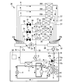
- FIG. 3 is a diagram showing a refrigeration cycle device 24 according to the second embodiment.
- the refrigeration cycle device 24 according to the second embodiment further includes a forward header 31, a return header 32, and an inter-header bypass valve 33.
- the forward header 31 has a predetermined volume.
- the return header 32 has a predetermined volume. Note that FIG. 3 shows a state in the free cooling combined operation mode.
- the outgoing header 31 includes an inlet 31a and a plurality of exits 31b.
- the inlet 31a is connected to the heat medium outlet of the second heat exchanger 5 by the heat medium passage 25.
- the second heat medium passage 9 connects one of the plurality of outlets 31b to the heat medium inlet of the second load device 200.
- the inlet of the second bypass valve 10 is connected to the other one of the plurality of outlets 31b.
- the return header 32 includes an exit 32a and a plurality of entrances 32b.
- the upstream portion of the return passage 11 is connected to the exit 32a.
- One of the plurality of inlets 32b is connected to the heat medium outlet of the first load device 100 by the heat medium passage 26.
- the other one of the plurality of inlets 32b is connected to the heat medium outlet of the second load device 200 by the heat medium passage 27.
- the inter-header bypass passage 28 returns the outgoing header 31 and connects it to the header 32.
- a header-to-header bypass valve 33 is provided in the header-to-header bypass passage 28. When the inter-header bypass valve 33 is opened, the heat medium can move between the forward header 31 and the return header 32 through the inter-header bypass passage 28.
- the difference between the pressure of the heat medium in the forward header 31 and the pressure of the heat medium in the return header 32 is referred to as "pressure difference between headers".
- the pressure difference between the headers can be adjusted by changing the opening degree of the bypass valve 33 between the headers.
- the control circuit 50 may be configured to control the operation of the inter-header bypass valve 33 so that the inter-header pressure difference detected by a sensor (not shown) meets the target.
- Embodiment 3 Next, the third embodiment will be described with reference to FIG. 4, but the differences between the first and second embodiments described above will be mainly described, and the elements common to or corresponding to the above-mentioned elements will be described. Have the same reference numerals to simplify or omit common descriptions.
- FIG. 4 is a diagram showing a refrigeration cycle device 30 according to the third embodiment.
- the refrigeration cycle device 30 according to the third embodiment further includes a forward header 31, a return header 32, and an inter-header bypass valve 33. Further, a plurality of first load devices 100 and a plurality of second load devices 200 are connected to the forward header 31 and the return header 32.
- the refrigeration cycle device 30 includes a plurality of second bypass valves 10 corresponding to the plurality of first load devices 100. Note that FIG. 4 shows a state in the free cooling combined operation mode.
- each second load device 200 is connected to one outlet 31b corresponding to the second load device 200 among the plurality of outlets 31b of the forward header 31 by the second heat medium passage 9. ing.
- the inlet of each second bypass valve 10 is connected to one outlet 31b corresponding to the second bypass valve 10 among the plurality of outlets 31b of the forward header 31 by a heat medium passage 34.
- the upstream portion of the heat medium passage 35 is connected to the outlet of the first bypass valve 8.
- the downstream portion of the heat medium passage 35 has a plurality of branch pipes 36 corresponding to the plurality of first load devices 100.
- Each branch pipe 36 is connected to the heat medium inlet of one of the first load devices 100 corresponding to the branch pipe 36 among the plurality of first load devices 100.
- Each branch pipe 36 is provided with a check valve 37 and a branch portion 38.
- the outlet of each second bypass valve 10 refers to the branch portion 38 of the branch pipe 36 connected to one first load device 100 corresponding to the second bypass valve 10 among the plurality of first load devices 100. And are connected by a heat medium passage 39.
- the heat medium flowing out from the second heat exchanger 5 to the forward header 31 corresponds to the second bypass valve 10 of the plurality of first load devices 100. It flows into one first load device 100. At this time, the check valve 37 prevents the heat medium from flowing into the other first load device 100.
- the system may be configured so that the number of the first load devices 100 operated among the plurality of first load devices 100 can be changed.
- the operation is performed by closing a valve (not shown) provided in each heat medium passage 26 or each branch pipe 36 to stop the supply of the heat medium to the first load device 100 for stopping the operation.
- the number of the first load devices 100 may be changed.
- the number of 100 may be changed.
- the system may be configured so that the number of the second load devices 200 operated among the plurality of second load devices 200 can be changed. For example, by closing the valve (not shown) provided in each second heat medium passage 9 or each heat medium passage 27, the supply of the heat medium to the second load device 200 for stopping the operation is stopped. , The number of second load devices 200 to be operated may be changed. Alternatively, a second load device operated by providing a bypass passage (not shown) that bypasses each second load device 200 and allowing a heat medium to flow so as to bypass the second load device 200 that stops operation. The number of 200 may be changed.
- the flow rate of the heat medium supplied to each first load device 100 and each second load device 200 are reached. It is possible to more reliably guarantee that the flow rate of the supplied heat medium is an appropriate value. In particular, even when the number of the first load devices 100 to be operated or the number of the second load devices 200 to be operated changes, it is possible to reliably supply a heat medium having an appropriate flow rate.
- the second heat exchanger 5 flows into the first load device 100 in the free cooling combined operation mode. It is possible to individually adjust the amount of heat medium to be used. For example, among the plurality of second bypass valves 10, by opening only the second bypass valve 10 corresponding to the first load device 100 having insufficient cooling capacity, only the first load device 100 having insufficient cooling capacity can be used.
- the heat medium can be supplied from the two heat exchangers 5.
- 1 refrigeration cycle device 2 compressor, 3 first heat exchanger, 4 decompression device, 5 second heat exchanger, 6 third heat exchanger, 7 first heat medium passage, 8 first bypass valve, 9 second Heat medium passage, 10 second bypass valve, 11 return passage, 12 flow path switching valve, 12a inlet, 12b first outlet, 12c second outlet, 13 heat medium pump, 14 blower, 15 outside air temperature sensor, 16 return temperature sensor , 17 branch part, 18 heat medium passage, 19 branch part, 20 branch part, 21 branch part, 22 heat medium passage, 23 refrigerant circuit switching valve, 24 refrigeration cycle device, 25 heat medium passage, 26 heat medium passage, 27 heat.
Landscapes
- Engineering & Computer Science (AREA)
- Mechanical Engineering (AREA)
- General Engineering & Computer Science (AREA)
- Physics & Mathematics (AREA)
- Thermal Sciences (AREA)
- Combustion & Propulsion (AREA)
- Chemical & Material Sciences (AREA)
- Signal Processing (AREA)
- Fuzzy Systems (AREA)
- Mathematical Physics (AREA)
- Life Sciences & Earth Sciences (AREA)
- Sustainable Development (AREA)
- Other Air-Conditioning Systems (AREA)
- Air Conditioning Control Device (AREA)
Abstract
Description
図1は、実施の形態1による冷凍サイクル装置1を示す図である。図1に示すように、冷凍サイクル装置1は、冷媒を圧縮する圧縮機2と、圧縮機2により圧縮された冷媒を室外空気により冷却する第一熱交換器3と、冷媒の圧力を低下させる減圧装置4と、減圧装置4により減圧された冷媒により熱媒を冷却する第二熱交換器5と、室外空気により熱媒を冷却する第三熱交換器6と、第三熱交換器6の熱媒出口を第二熱交換器5の熱媒入口につなぐ第一熱媒通路7と、第一熱媒通路7から熱媒を第一負荷装置100に流入させる第一バイパス弁8と、第二熱交換器5から流出した熱媒を第二負荷装置200に流入させる第二熱媒通路9と、第二熱交換器5から流出した熱媒を第一負荷装置100に流入させる第二バイパス弁10と、第一負荷装置100から還った熱媒と、第二負荷装置200から還った熱媒とが通る還り通路11と、熱媒が還り通路11から第三熱交換器6を通らずに第一熱媒通路7に流入する第一モードと、熱媒が還り通路11から第三熱交換器6に流入する第二モードとを切り替える流路切替弁12とを備えている。
図1は、チラー単独運転モードで冷凍サイクル装置1が運転されている状態を示している。チラー単独運転モードでは、第三熱交換器6によるフリークーリングを行うことなく、圧縮機2を作動させることで、熱媒が冷却される。チラー単独運転モードのときの冷凍サイクル装置1は、以下のように作動する。圧縮機2により圧縮された高温高圧の冷媒が第一熱交換器3に流入する。第一熱交換器3にて室外空気により冷却された冷媒は、減圧装置4を通るときに減圧される。第一バイパス弁8は、閉じている。第二バイパス弁10は、開いている。流路切替弁12は、第一モードにある。第二熱交換器5では、減圧装置4から流出した低温低圧の冷媒と、熱媒との間で熱が交換されることで、熱媒が冷却される。第二熱交換器5から流出した熱媒の一部は、第二バイパス弁10を通って、第一負荷装置100へ供給される。第二熱交換器5から流出した熱媒の残りは、第二熱媒通路9を通って、第二負荷装置200へ供給される。第一負荷装置100から還った熱媒と、第二負荷装置200から還った熱媒とが合流して還り通路11を流れる。熱媒は、還り通路11から第三熱交換器6を通らずに第一熱媒通路7に流入する。第一熱媒通路7に流入した熱媒の全量が第二熱交換器5に流入する。
図2は、フリークーリング併用運転モードで冷凍サイクル装置1が運転されている状態を示す図である。フリークーリング併用運転モードでは、第三熱交換器6によるフリークーリングと、圧縮機2の作動とを併用することで、熱媒が冷却される。フリークーリング併用運転モードのときの冷凍サイクル装置1は、以下のように作動する。冷媒は、チラー単独運転モードのときと同じ経路を通って循環する。第一バイパス弁8は、開いている。第二バイパス弁10は、閉じている。流路切替弁12は、第二モードにある。第一負荷装置100から還った熱媒と、第二負荷装置200から還った熱媒とが合流して還り通路11を流れる。還り通路11を通過した熱媒は、第三熱交換器6に流入する。第三熱交換器6にて室外空気により冷却された熱媒は、第一熱媒通路7に流入する。第一熱媒通路7を流れる熱媒の一部は、第一バイパス弁8を通って、第一負荷装置100へ供給される。第一熱媒通路7を流れる熱媒の残りは、第二熱交換器5に流入する。第二熱交換器5にて冷媒により冷却された熱媒は、第二熱媒通路9を通って、第二負荷装置200へ供給される。
図示を省略するが、冷凍サイクル装置1は、圧縮機2を作動させることなく、フリークーリングのみにより熱媒を冷却するフリークーリング単独運転モードで運転されてもよい。フリークーリング単独運転モードでは、圧縮機2が停止され、流路切替弁12が第二モードとされ、第一バイパス弁8が開かれ、第二バイパス弁10が全閉とされる。
次に、図3を参照して、実施の形態2について説明するが、前述した実施の形態1との相違点を中心に説明し、前述した要素と共通または対応する要素には、同一の符号を付して、共通する説明を簡略化または省略する。
次に、図4を参照して、実施の形態3について説明するが、前述した実施の形態1及び実施の形態2との相違点を中心に説明し、前述した要素と共通または対応する要素には、同一の符号を付して、共通する説明を簡略化または省略する。
Claims (7)
- 冷媒を圧縮する圧縮機と、
前記圧縮機により圧縮された前記冷媒を室外空気により冷却する第一熱交換器と、
前記冷媒の圧力を低下させる減圧装置と、
前記減圧装置により減圧された前記冷媒により熱媒を冷却する第二熱交換器と、
前記室外空気により前記熱媒を冷却する第三熱交換器と、
前記第三熱交換器の熱媒出口を前記第二熱交換器の熱媒入口につなぐ第一熱媒通路と、
前記第一熱媒通路から前記熱媒を第一負荷装置に流入させる第一バイパス弁と、
前記第二熱交換器から流出した前記熱媒を第二負荷装置に流入させる第二熱媒通路と、
前記第二熱交換器から流出した前記熱媒を前記第一負荷装置に流入させる第二バイパス弁と、
前記第一負荷装置から還った前記熱媒と、前記第二負荷装置から還った前記熱媒とが通る還り通路と、
前記熱媒が前記還り通路から前記第三熱交換器を通らずに前記第一熱媒通路に流入する第一モードと、前記熱媒が前記還り通路から前記第三熱交換器に流入する第二モードとを切り替える流路切替弁と、
を備える冷凍サイクル装置。 - 前記第一バイパス弁の動作と、前記第二バイパス弁の動作と、前記流路切替弁の動作とを制御する制御回路をさらに備える請求項1に記載の冷凍サイクル装置。
- 前記室外空気の温度である外気温度を検出する外気温度センサと、
前記還り通路を通る前記熱媒の温度である還り温度を検出する還り温度センサと、
をさらに備え、
前記制御回路は、前記還り温度よりも前記外気温度が低く、かつ、前記還り温度と前記外気温度との差が基準に比べて大きい場合に、前記流路切替弁を前記第二モードに切り替える請求項2に記載の冷凍サイクル装置。 - 前記流路切替弁が前記第一モードにあるときに、前記制御回路は、前記第一バイパス弁を閉じて前記第二バイパス弁を開き、
前記流路切替弁が前記第二モードにあるときに、前記制御回路は、前記第一バイパス弁を開く処理と、前記第二バイパス弁を閉じるか前記第二バイパス弁の開度を前記第一モードのときの開度よりも小さくする処理とを行う前記請求項2または請求項3に記載の冷凍サイクル装置。 - 前記冷凍サイクル装置が前記第一負荷装置及び前記第二負荷装置へ供給する前記熱媒による冷却能力である供給冷却能力の不足を検出する能力不足検出部をさらに備え、
前記流路切替弁が前記第二モードにあるときに前記供給冷却能力が不足すると、前記制御回路は、前記第一バイパス弁の開度を低下させ、かつ、前記第二バイパス弁の開度を増大させる請求項2から請求項4のいずれか一項に記載の冷凍サイクル装置。 - 室内空気と前記熱媒との間で熱を交換する熱交換器を有する前記第一負荷装置と、
室外から室内へ流入する換気空気と前記熱媒との間で熱を交換する熱交換器を有する前記第二負荷装置と、
を備える請求項1から請求項5のいずれか一項に記載の冷凍サイクル装置。 - 前記第二熱交換器の熱媒出口、前記第二バイパス弁、及び前記第二熱媒通路のそれぞれに接続された往きヘッダーと、
前記還り通路、前記第一負荷装置、及び前記第二負荷装置のそれぞれに接続された還りヘッダーと、
前記往きヘッダーを前記還りヘッダーにつなぐヘッダー間バイパス通路と、
前記ヘッダー間バイパス通路に設けられたヘッダー間バイパス弁と、
をさらに備える請求項1から請求項6のいずれか一項に記載の冷凍サイクル装置。
Priority Applications (5)
| Application Number | Priority Date | Filing Date | Title |
|---|---|---|---|
| CN202080101142.0A CN115667815A (zh) | 2020-05-28 | 2020-05-28 | 制冷循环装置 |
| EP20937397.6A EP4160107A4 (en) | 2020-05-28 | 2020-05-28 | REFRIGERATION CYCLE DEVICE |
| JP2022527397A JP7306582B2 (ja) | 2020-05-28 | 2020-05-28 | 冷凍サイクル装置 |
| US17/911,837 US20230137885A1 (en) | 2020-05-28 | 2020-05-28 | Refrigeration cycle apparatus |
| PCT/JP2020/021141 WO2021240729A1 (ja) | 2020-05-28 | 2020-05-28 | 冷凍サイクル装置 |
Applications Claiming Priority (1)
| Application Number | Priority Date | Filing Date | Title |
|---|---|---|---|
| PCT/JP2020/021141 WO2021240729A1 (ja) | 2020-05-28 | 2020-05-28 | 冷凍サイクル装置 |
Publications (1)
| Publication Number | Publication Date |
|---|---|
| WO2021240729A1 true WO2021240729A1 (ja) | 2021-12-02 |
Family
ID=78723132
Family Applications (1)
| Application Number | Title | Priority Date | Filing Date |
|---|---|---|---|
| PCT/JP2020/021141 Ceased WO2021240729A1 (ja) | 2020-05-28 | 2020-05-28 | 冷凍サイクル装置 |
Country Status (5)
| Country | Link |
|---|---|
| US (1) | US20230137885A1 (ja) |
| EP (1) | EP4160107A4 (ja) |
| JP (1) | JP7306582B2 (ja) |
| CN (1) | CN115667815A (ja) |
| WO (1) | WO2021240729A1 (ja) |
Cited By (2)
| Publication number | Priority date | Publication date | Assignee | Title |
|---|---|---|---|---|
| WO2025203468A1 (ja) * | 2024-03-28 | 2025-10-02 | 三菱電機株式会社 | 空気調和装置 |
| WO2026078959A1 (ja) * | 2024-10-07 | 2026-04-16 | 株式会社デンソー | 冷凍サイクル装置 |
Citations (4)
| Publication number | Priority date | Publication date | Assignee | Title |
|---|---|---|---|---|
| JPH0719523A (ja) * | 1991-01-31 | 1995-01-20 | Sanki Eng Co Ltd | 自然冷却空調装置 |
| JP2006275323A (ja) * | 2005-03-28 | 2006-10-12 | Sanki Eng Co Ltd | 熱源システム最適運転制御方法及び装置 |
| JP2010107184A (ja) * | 2008-09-30 | 2010-05-13 | Hitachi Plant Technologies Ltd | 空調方法及び空調システム |
| JP5503461B2 (ja) * | 2010-08-26 | 2014-05-28 | 株式会社朝日工業社 | フリークーリングを用いた空調運転方法 |
Family Cites Families (13)
| Publication number | Priority date | Publication date | Assignee | Title |
|---|---|---|---|---|
| US6082128A (en) * | 1998-11-12 | 2000-07-04 | Daimlerchrysler Corporation | Reversible air conditioning and heat pump HVAC system for electric vehicles |
| AU751294C (en) * | 2001-07-13 | 2005-04-07 | Baltimore Aircoil Company Inc. | System and method of cooling |
| JP4829147B2 (ja) * | 2007-03-01 | 2011-12-07 | 三機工業株式会社 | 空気調和設備 |
| US7997092B2 (en) * | 2007-09-26 | 2011-08-16 | Carrier Corporation | Refrigerant vapor compression system operating at or near zero load |
| CN201539928U (zh) * | 2009-09-09 | 2010-08-04 | 北京康孚环境控制有限公司 | 冷却塔和冷水机组联合供冷系统 |
| JP6314821B2 (ja) * | 2014-01-29 | 2018-04-25 | 株式会社デンソー | 車両用空調装置 |
| JP6385436B2 (ja) * | 2014-07-18 | 2018-09-05 | 三菱電機株式会社 | 空気調和装置 |
| US10520233B2 (en) * | 2015-01-13 | 2019-12-31 | Mitsubishi Electric Corporation | Air-conditioning apparatus for a plurality of parallel outdoor units |
| US10655504B2 (en) * | 2016-05-27 | 2020-05-19 | Denso International America, Inc. | Heat pump for warming engine coolant |
| EP3561407B1 (en) * | 2016-12-21 | 2022-08-31 | Mitsubishi Electric Corporation | Air conditioner |
| JP7316872B2 (ja) * | 2019-08-06 | 2023-07-28 | サンデン株式会社 | 車両搭載発熱機器の温度調整装置及びそれを備えた車両用空気調和装置 |
| CN110513900A (zh) * | 2019-08-23 | 2019-11-29 | 捷通智慧科技股份有限公司 | 一种基于闭式冷却塔与冷水机组联合使用的冷却装置 |
| JP7243694B2 (ja) * | 2019-10-15 | 2023-03-22 | 株式会社デンソー | 冷凍サイクル装置 |
-
2020
- 2020-05-28 CN CN202080101142.0A patent/CN115667815A/zh active Pending
- 2020-05-28 WO PCT/JP2020/021141 patent/WO2021240729A1/ja not_active Ceased
- 2020-05-28 JP JP2022527397A patent/JP7306582B2/ja active Active
- 2020-05-28 US US17/911,837 patent/US20230137885A1/en not_active Abandoned
- 2020-05-28 EP EP20937397.6A patent/EP4160107A4/en not_active Withdrawn
Patent Citations (4)
| Publication number | Priority date | Publication date | Assignee | Title |
|---|---|---|---|---|
| JPH0719523A (ja) * | 1991-01-31 | 1995-01-20 | Sanki Eng Co Ltd | 自然冷却空調装置 |
| JP2006275323A (ja) * | 2005-03-28 | 2006-10-12 | Sanki Eng Co Ltd | 熱源システム最適運転制御方法及び装置 |
| JP2010107184A (ja) * | 2008-09-30 | 2010-05-13 | Hitachi Plant Technologies Ltd | 空調方法及び空調システム |
| JP5503461B2 (ja) * | 2010-08-26 | 2014-05-28 | 株式会社朝日工業社 | フリークーリングを用いた空調運転方法 |
Non-Patent Citations (1)
| Title |
|---|
| See also references of EP4160107A4 * |
Cited By (2)
| Publication number | Priority date | Publication date | Assignee | Title |
|---|---|---|---|---|
| WO2025203468A1 (ja) * | 2024-03-28 | 2025-10-02 | 三菱電機株式会社 | 空気調和装置 |
| WO2026078959A1 (ja) * | 2024-10-07 | 2026-04-16 | 株式会社デンソー | 冷凍サイクル装置 |
Also Published As
| Publication number | Publication date |
|---|---|
| JP7306582B2 (ja) | 2023-07-11 |
| EP4160107A1 (en) | 2023-04-05 |
| CN115667815A (zh) | 2023-01-31 |
| JPWO2021240729A1 (ja) | 2021-12-02 |
| US20230137885A1 (en) | 2023-05-04 |
| EP4160107A4 (en) | 2023-07-12 |
Similar Documents
| Publication | Publication Date | Title |
|---|---|---|
| US20250085036A1 (en) | Air conditioning system with capacity control and controlled hot water generation | |
| JP6685409B2 (ja) | 空気調和装置 | |
| JP6644154B2 (ja) | 空気調和装置 | |
| JP3943092B2 (ja) | 空気調和機及びその制御方法 | |
| KR101146460B1 (ko) | 냉매시스템 | |
| US9279591B2 (en) | Air-conditioning apparatus | |
| EP2541169A1 (en) | Air conditioner and air-conditioning hot-water-supplying system | |
| WO2020186906A1 (zh) | 空调器化霜控制方法及空调器 | |
| JP5872052B2 (ja) | 空気調和装置 | |
| KR101973204B1 (ko) | 냉장 냉동 복합 시스템 및 그 제어방법 | |
| JP2023503192A (ja) | 空気調和装置 | |
| KR100822432B1 (ko) | 보조 열교환기를 갖는 공기조화기 | |
| WO2021014520A1 (ja) | 空気調和装置 | |
| JP7306582B2 (ja) | 冷凍サイクル装置 | |
| WO2022239212A1 (ja) | 空気調和装置、及び空気調和システム | |
| KR102059047B1 (ko) | 히트펌프 시스템 및 그 제어방법 | |
| JP2008175430A (ja) | 空気調和機 | |
| JP2015117902A (ja) | 冷凍サイクル装置 | |
| JP2018063090A (ja) | 冷暖房機能付きヒートポンプ給湯機 | |
| EP3715735B1 (en) | Air conditioning apparatus | |
| WO2022230034A1 (ja) | 空気調和装置 | |
| JP2013117360A (ja) | 空気調和装置及び方法 | |
| CN216203942U (zh) | 热泵系统 | |
| US11397015B2 (en) | Air conditioning apparatus | |
| JP7394876B2 (ja) | 空気調和装置 |
Legal Events
| Date | Code | Title | Description |
|---|---|---|---|
| 121 | Ep: the epo has been informed by wipo that ep was designated in this application |
Ref document number: 20937397 Country of ref document: EP Kind code of ref document: A1 |
|
| ENP | Entry into the national phase |
Ref document number: 2022527397 Country of ref document: JP Kind code of ref document: A |
|
| NENP | Non-entry into the national phase |
Ref country code: DE |
|
| ENP | Entry into the national phase |
Ref document number: 2020937397 Country of ref document: EP Effective date: 20230102 |
|
| WWW | Wipo information: withdrawn in national office |
Ref document number: 2020937397 Country of ref document: EP |