WO2021246490A1 - 地切り制御装置、及び、クレーン - Google Patents
地切り制御装置、及び、クレーン Download PDFInfo
- Publication number
- WO2021246490A1 WO2021246490A1 PCT/JP2021/021225 JP2021021225W WO2021246490A1 WO 2021246490 A1 WO2021246490 A1 WO 2021246490A1 JP 2021021225 W JP2021021225 W JP 2021021225W WO 2021246490 A1 WO2021246490 A1 WO 2021246490A1
- Authority
- WO
- WIPO (PCT)
- Prior art keywords
- boom
- ground cutting
- load
- control device
- winch
- Prior art date
- Legal status (The legal status is an assumption and is not a legal conclusion. Google has not performed a legal analysis and makes no representation as to the accuracy of the status listed.)
- Ceased
Links
Images




Classifications
-
- B—PERFORMING OPERATIONS; TRANSPORTING
- B66—HOISTING; LIFTING; HAULING
- B66C—CRANES; LOAD-ENGAGING ELEMENTS OR DEVICES FOR CRANES, CAPSTANS, WINCHES, OR TACKLES
- B66C13/00—Other constructional features or details
- B66C13/04—Auxiliary devices for controlling movements of suspended loads, or preventing cable slack
- B66C13/06—Auxiliary devices for controlling movements of suspended loads, or preventing cable slack for minimising or preventing longitudinal or transverse swinging of loads
- B66C13/063—Auxiliary devices for controlling movements of suspended loads, or preventing cable slack for minimising or preventing longitudinal or transverse swinging of loads electrical
-
- B—PERFORMING OPERATIONS; TRANSPORTING
- B66—HOISTING; LIFTING; HAULING
- B66C—CRANES; LOAD-ENGAGING ELEMENTS OR DEVICES FOR CRANES, CAPSTANS, WINCHES, OR TACKLES
- B66C13/00—Other constructional features or details
- B66C13/04—Auxiliary devices for controlling movements of suspended loads, or preventing cable slack
- B66C13/06—Auxiliary devices for controlling movements of suspended loads, or preventing cable slack for minimising or preventing longitudinal or transverse swinging of loads
- B66C13/066—Auxiliary devices for controlling movements of suspended loads, or preventing cable slack for minimising or preventing longitudinal or transverse swinging of loads for minimising vibration of a boom
-
- B—PERFORMING OPERATIONS; TRANSPORTING
- B66—HOISTING; LIFTING; HAULING
- B66C—CRANES; LOAD-ENGAGING ELEMENTS OR DEVICES FOR CRANES, CAPSTANS, WINCHES, OR TACKLES
- B66C13/00—Other constructional features or details
- B66C13/16—Applications of indicating, registering, or weighing devices
-
- B—PERFORMING OPERATIONS; TRANSPORTING
- B66—HOISTING; LIFTING; HAULING
- B66C—CRANES; LOAD-ENGAGING ELEMENTS OR DEVICES FOR CRANES, CAPSTANS, WINCHES, OR TACKLES
- B66C13/00—Other constructional features or details
- B66C13/18—Control systems or devices
- B66C13/46—Position indicators for suspended loads or for crane elements
-
- B—PERFORMING OPERATIONS; TRANSPORTING
- B66—HOISTING; LIFTING; HAULING
- B66C—CRANES; LOAD-ENGAGING ELEMENTS OR DEVICES FOR CRANES, CAPSTANS, WINCHES, OR TACKLES
- B66C13/00—Other constructional features or details
- B66C13/18—Control systems or devices
- B66C13/48—Automatic control of crane drives for producing a single or repeated working cycle; Program control
-
- B—PERFORMING OPERATIONS; TRANSPORTING
- B66—HOISTING; LIFTING; HAULING
- B66C—CRANES; LOAD-ENGAGING ELEMENTS OR DEVICES FOR CRANES, CAPSTANS, WINCHES, OR TACKLES
- B66C23/00—Cranes comprising essentially a beam, boom, or triangular structure acting as a cantilever and mounted for translatory of swinging movements in vertical or horizontal planes or a combination of such movements, e.g. jib-cranes, derricks, tower cranes
- B66C23/18—Cranes comprising essentially a beam, boom, or triangular structure acting as a cantilever and mounted for translatory of swinging movements in vertical or horizontal planes or a combination of such movements, e.g. jib-cranes, derricks, tower cranes specially adapted for use in particular purposes
- B66C23/36—Cranes comprising essentially a beam, boom, or triangular structure acting as a cantilever and mounted for translatory of swinging movements in vertical or horizontal planes or a combination of such movements, e.g. jib-cranes, derricks, tower cranes specially adapted for use in particular purposes mounted on road or rail vehicles; Manually-movable jib-cranes for use in workshops; Floating cranes
-
- B—PERFORMING OPERATIONS; TRANSPORTING
- B66—HOISTING; LIFTING; HAULING
- B66C—CRANES; LOAD-ENGAGING ELEMENTS OR DEVICES FOR CRANES, CAPSTANS, WINCHES, OR TACKLES
- B66C23/00—Cranes comprising essentially a beam, boom, or triangular structure acting as a cantilever and mounted for translatory of swinging movements in vertical or horizontal planes or a combination of such movements, e.g. jib-cranes, derricks, tower cranes
- B66C23/18—Cranes comprising essentially a beam, boom, or triangular structure acting as a cantilever and mounted for translatory of swinging movements in vertical or horizontal planes or a combination of such movements, e.g. jib-cranes, derricks, tower cranes specially adapted for use in particular purposes
- B66C23/36—Cranes comprising essentially a beam, boom, or triangular structure acting as a cantilever and mounted for translatory of swinging movements in vertical or horizontal planes or a combination of such movements, e.g. jib-cranes, derricks, tower cranes specially adapted for use in particular purposes mounted on road or rail vehicles; Manually-movable jib-cranes for use in workshops; Floating cranes
- B66C23/42—Cranes comprising essentially a beam, boom, or triangular structure acting as a cantilever and mounted for translatory of swinging movements in vertical or horizontal planes or a combination of such movements, e.g. jib-cranes, derricks, tower cranes specially adapted for use in particular purposes mounted on road or rail vehicles; Manually-movable jib-cranes for use in workshops; Floating cranes with jibs of adjustable configuration, e.g. foldable
-
- B—PERFORMING OPERATIONS; TRANSPORTING
- B66—HOISTING; LIFTING; HAULING
- B66C—CRANES; LOAD-ENGAGING ELEMENTS OR DEVICES FOR CRANES, CAPSTANS, WINCHES, OR TACKLES
- B66C23/00—Cranes comprising essentially a beam, boom, or triangular structure acting as a cantilever and mounted for translatory of swinging movements in vertical or horizontal planes or a combination of such movements, e.g. jib-cranes, derricks, tower cranes
- B66C23/88—Safety gear
-
- B—PERFORMING OPERATIONS; TRANSPORTING
- B66—HOISTING; LIFTING; HAULING
- B66C—CRANES; LOAD-ENGAGING ELEMENTS OR DEVICES FOR CRANES, CAPSTANS, WINCHES, OR TACKLES
- B66C2700/00—Cranes
- B66C2700/03—Cranes with arms or jibs; Multiple cranes
- B66C2700/0321—Travelling cranes
- B66C2700/0357—Cranes on road or off-road vehicles, on trailers or towed vehicles; Cranes on wheels or crane-trucks
- B66C2700/0364—Cranes on road or off-road vehicles, on trailers or towed vehicles; Cranes on wheels or crane-trucks with a slewing arm
- B66C2700/0371—Cranes on road or off-road vehicles, on trailers or towed vehicles; Cranes on wheels or crane-trucks with a slewing arm on a turntable
Definitions
- the present invention relates to a ground cutting control device and a crane for suppressing load runout when lifting a suspended load from the ground.
- the vertical ground cutting control device described in Patent Document 1 detects the engine rotation speed by an engine rotation speed sensor and raises and lowers the boom. It is configured to correct to a value according to the engine speed.
- an object of the present invention is to provide a ground cutting control device capable of quickly grounding a suspended load while suppressing load runout, and a crane equipped with a ground cutting control device.
- ground cutting control device is a ground cutting control device that is mounted on a crane having a boom and a winch that winds up a wire rope and controls the ground cutting of suspended loads.
- a load detector that detects the load acting on the boom, It is equipped with a control unit that controls the winding operation of the winch and the raising and lowering operation of the boom.
- the control unit controls the raising and lowering of the boom by a control signal that is generated based on the time change of the detection value of the load detection unit and applies a filter that attenuates the frequency component in a predetermined range, and causes the sway of the suspended load. Suppress.
- a ground cutting control device capable of quickly grounding a suspended load while suppressing load runout, and a crane equipped with a ground cutting control device.
- FIG. 1 is an explanatory diagram illustrating load runout of a suspended load.
- FIG. 2 is a side view of the mobile crane.
- FIG. 3 is a block diagram of the ground cutting control device.
- FIG. 4 is a block diagram of the entire ground cutting control device.
- FIG. 5 is a block diagram of ground cutting control.
- FIG. 6 is a block diagram relating to the application of the band removal filter.
- FIG. 7 is a flowchart of ground cutting control.
- FIG. 8 is a graph illustrating a method for determining ground cutting.
- FIG. 9 is a graph showing the relationship between load and undulation angle.
- FIG. 10 is an explanatory diagram of the notch filter characteristics.
- examples of the mobile crane include a rough terrain crane, an all terrain crane, and a truck crane.
- a rough terrain crane will be described as an example of the work vehicle according to the present embodiment, but the ground cutting control device according to the present invention can also be applied to other mobile cranes. Further, the ground cutting control device according to the present invention can be applied to a crawler crane and a tower crane.
- the rough terrain crane 1 of the present embodiment can turn horizontally to the vehicle body 10 which is the main body portion of the vehicle having a traveling function, the outriggers 11 provided at the four corners of the vehicle body 10, and the vehicle body 10. It includes a swivel base 12 attached and a boom 14 attached to the rear of the swivel base 12.
- the out trigger 11 can slide out / slide outward from the vehicle body 10 in the width direction, and by expanding and contracting the jack cylinder, the jack can be extended / jack stored in the vertical direction from the vehicle body 10. Is.
- the swivel base 12 has a pinion gear to which the power of the swivel motor 61 is transmitted, and the pinion gear meshes with a circular gear provided on the vehicle body 10 to rotate around a swivel shaft.
- the swivel table 12 has a cockpit 18 arranged on the right front side and a counterweight 19 arranged on the rear side.
- a winch 13 for winding and lowering the wire rope 16 is arranged behind the swivel table 12.
- the winch 13 By rotating the winch motor 64 in the forward direction or the reverse direction, the winch 13 rotates in two directions, a winding direction (winding direction) and a winding direction (feeding direction).
- the boom 14 is configured in a nested manner by a base end boom 141, an intermediate boom 142 (s), and a tip boom 143, and expands and contracts by a telescopic cylinder 63 arranged inside.
- a sheave is arranged on the state-of-the-art boom head 144 of the tip boom 143, and a wire rope 16 is hung around the sheave to hang a hook 17.
- the base end portion of the base end boom 141 is rotatably attached to a support shaft installed on the swivel base 12.
- the base end boom 141 can undulate up and down with the support shaft as the center of rotation.
- An undulating cylinder 62 is bridged between the swivel base 12 and the lower surface of the base end boom 141. By expanding and contracting the undulating cylinder 62, the entire boom 14 is undulated.
- the ground cutting control device D is configured around a controller 40 as a control unit.
- the controller 40 is a general-purpose microcomputer having an input port, an output port, an arithmetic unit, and the like.
- the controller 40 receives an operation signal from the operation levers 51 to 54 (swivel lever 51, undulation lever 52, telescopic lever 53, winch lever 54), and the actuators 61 to 64 (swivel motor 61, via a control valve (not shown)).
- the undulating cylinder 62, the telescopic cylinder 63, and the winch motor 64 are controlled.
- the controller 40 of the present embodiment includes a ground cutting switch 20A for starting or stopping the ground cutting control, a winch speed setting means 20B for setting the speed of the winch 13 in the ground cutting control, and a boom 14.
- a pressure measuring instrument 21 as a load detecting unit for detecting an acting load, an attitude measuring means 23 for detecting the attitude information of the boom 14, and a rotation speed measuring instrument 22 for measuring the rotation speed of the winch 13 are connected. Has been done.
- the posture measuring means 23 corresponds to an example of the posture detecting unit.
- the ground cutting switch 20A is an input device for instructing the start or stop of ground cutting control.
- the ground cutting switch 20A may be configured to be added to the safety device of the rough terrain crane 1, for example.
- the ground cutting switch 20A is preferably arranged in the cockpit 18.
- the winch speed setting means 20B is an input device for setting the speed of the winch 13 in the ground cutting control.
- the winch speed setting means 20B includes a method of selecting an appropriate speed from preset speeds and a method of inputting with a numeric keypad. Further, the winch speed setting means 20B may be configured to be added to the safety device of the rough terrain crane 1 in the same manner as the ground cutting switch 20A.
- the winch speed setting means 20B is preferably arranged in the cockpit 18. By adjusting the speed of the winch 13 by the winch speed setting means 20B, the time required for ground cutting control can be adjusted.
- the pressure measuring instrument 21 as a load detecting unit is a measuring device that measures the load acting on the boom 14.
- the pressure measuring instrument 21 is, for example, a pressure gauge that measures the pressure acting on the undulating cylinder 62.
- the pressure signal measured by the pressure measuring instrument 21 is transmitted to the controller 40.
- the rotation speed measuring instrument 22 is installed near the rotation axis of the winch (drum) 13 and measures the rotation speed (rotation speed) of the winch (drum) 13.
- the rotation speed (rotational speed) measured by the rotation speed measuring instrument 22 is transmitted to the controller 40 and used for calculating the winch winding speed and the length of the wire rope.
- the posture measuring means 23 is a measuring device that detects the posture information of the boom 14, and is composed of an undulation angle meter 231 that measures the undulation angle of the boom 14 and an undulation angular velocity meter 232 that measures the undulation angular velocity.
- the undulation angle meter 231 is, for example, a potentiometer.
- the undulation angular velocity meter 232 is, for example, a stroke sensor attached to the undulation cylinder 15. The undulation angle signal measured by the undulation angle meter 231 and the undulation angular velocity signal measured by the undulation angular velocity meter 232 are transmitted to the controller 40.
- the controller 40 is a control unit that controls the operation of the boom 14 and the winch 13.
- the controller 40 is based on the time change of the load measured by the pressure measuring device 21 as the load detecting unit when the winch 13 is wound up and the suspended load is grounded by turning on the ground cutting switch 20A.
- the amount of change in the undulation angle of the boom 14 is predicted, and the boom 14 is raised to compensate for the predicted amount of change.
- the controller 40 corresponds to an example of a control unit, and as a functional unit, the selection function unit 40a of the characteristic table or the transfer function and the ground cutting by determining whether or not the ground is actually cut. It has a ground cutting determination function unit 40b for stopping control.
- the selection function unit 40a of the characteristic table or the transfer function inputs the initial value of the pressure from the pressure measuring instrument 21 as the load detection unit and the initial value of the undulation angle from the undulation angle meter 231 as the attitude detection unit. Receive and determine the characteristic table or transfer function to apply.
- the transfer function a relationship using the linear coefficient a can be applied as follows.
- the load and undulation angle (tip-to-ground angle) are adjusted so that the boom tip position is always directly above the suspended load so that load runout does not occur.
- the load Load 1 changes to Load 2 between time t 1 and time t 2 during the ground cutting
- the relationship between the undulation angle ⁇ and the load Road the relationship between the undulation angle ⁇ 1 and the load Load 1
- the relationship between the undulation angle ⁇ 2 and the load Load 2 is expressed by the following equation.
- a is a constant (linear coefficient). That is, in the undulation angle control, the time change (differentiation) of the load is input.
- the ground cutting determination function unit 40b monitors the time series data of the load value calculated from the pressure signal from the pressure measuring instrument 21 as the load detecting unit, and determines the presence or absence of ground cutting. The method of determining the ground cutting will be described later with reference to FIG.
- the load change calculation unit 71 the load change is calculated based on the time series data of the load measured by the pressure measuring instrument 21 as the load detection unit.
- the calculated load change is input to the target shaft velocity calculation unit 72.
- the input / output relationship in the target axis speed calculation unit 72 will be described later with reference to FIG.
- the target shaft speed calculation unit 72 calculates the target shaft speed based on the initial value of the undulation angle, the set winch speed, and the input load change.
- the target axis velocity is here the target undulation angular velocity (and, but not required, the target winch velocity).
- the calculated target axis speed is input to the axis speed controller 73.
- the control of the first half up to this point is the process related to the ground cutting control of the present embodiment.
- the operation amount is input to the control target 75 via the axis speed controller 73 and the operation amount conversion processing unit 74 of the axis speed.
- the control of the latter half is a process related to normal control, and feedback control is performed based on the measured undulation angular velocity.
- the input / output relationship of the elements in the target axis velocity calculation unit 72 of the ground cutting control will be described with reference to the block diagram of FIG.
- the initial value of the undulation angle is input to the selection function unit 81 (40a) of the characteristic table / transfer function.
- the selection function unit 81 the most appropriate constant (linear coefficient) a is selected by using the characteristic table (lookuptable) or the transfer function (expression).
- the numerical differentiation unit 82 the numerical differentiation (differentiation with respect to time) of the load change is performed, and the target undulation angle velocity is calculated by multiplying the result of this numerical differentiation by the constant a. That is, the target undulation angular velocity is calculated by executing the above-mentioned calculation (Equation 3). In this way, the control of the target undulation angular velocity is feedforward controlled using the characteristic table (or transfer function).
- the second control signal generation unit 92 instructs the PID control unit 94 of the target undulation angular velocity based on the target undulation angle ⁇ d and the measured undulation angular velocity.
- the PID control unit 94 generates an undulation angular velocity control signal by PID control. That is, the undulation angular velocity control signal is generated based on the difference between the measured undulation angular velocity and the target undulation angular velocity.
- This undulation angular velocity control is feedback controlled based on the measured load and the measured undulation angular velocity (see FIGS. 4 and 5).
- the measured load pressure value
- the filter application unit 95 is used for ground cutting determination to trigger the activation of the filter application unit 95.
- the controller 40 determines whether or not there is a ground cut based on the time-series data of the measured rope length or the time-series data of the measured load (pressure value).
- the filter application unit 95 applies a band removal filter that attenuates a predetermined band to the undulation angular velocity control signal.
- the filter application unit 95 does not apply the band removal filter to the undulation angular velocity control signal.
- the filter application unit 95 may always apply the band removal filter to the undulation angular velocity control signal regardless of whether or not the ground cutting is completed.
- the band elimination filter (band stop filter) is applied when the undulation angular velocity control signal is generated.
- the band-stop filter has a frequency characteristic that allows most frequencies to pass through as it is, but attenuates only a predetermined range of frequency components to a very low level.
- As the band elimination filter it is preferable to use a notch filter having a narrow blocking band. In the following embodiment, a specific example to which the notch filter is applied will be described, but this is an example, and another band removal filter can also be used.
- the characteristics of the notch filter are shown in the explanatory diagram of FIG.
- the notch filter when the notch filter is applied, the amplitude is greatly attenuated before and after the center frequency.
- the phase lag characteristic is obtained on the lower frequency side than the center frequency, and the phase lead characteristic is obtained on the high frequency side.
- the natural frequency of the boom 14 depends on the state of the boom 14.
- the state of the boom 14 is, for example, the length of the boom 14 and / or the expansion / contraction pattern of the boom 14. That is, even if the length of the boom 14 is the same, if the expansion / contraction pattern of the boom 14 is different, the natural frequency of the boom 14 is different.
- the mobile crane it is preferable to calculate and measure the natural frequency for each length of the boom 14 and / or for each expansion / contraction pattern in advance and store it. That is, it is preferable that the storage unit of the mobile crane stores the natural frequency in association with the length and / or expansion / contraction pattern of the boom 14. It is also preferable to actually measure the natural frequency of the work vehicle for each vehicle when shipping from the factory.
- the target speed of the winch 13 is set via the winch speed setting means 20B before or after the start of the ground cutting control.
- the controller 40 starts winch control at the target speed (step S1).
- This target speed is, for example, a constant speed.
- Step S2 the suspended load load measurement (undulating cylinder pressure detection) is started by the pressure measuring instrument 21 as the load detecting unit, and the load value (pressure value) is input to the controller 40 (. Step S2).
- the selection function unit 40a receives the input of the initial value of the load value (pressure value) and the initial value of the undulation angle from the undulation angle meter 231 as the attitude detection unit, and applies the characteristic table or transmission.
- the function is determined (step S3).
- the controller 40 the undulation angular velocity is calculated based on the applied characteristic table or transfer function and the load change (step S3). That is, the undulation angular velocity is controlled by the feedforward control. Twice
- a time-series change in rope length is detected for use in later ground cutting determination (step S4).
- the measurement result of the rotation speed measured by the rotation speed measuring instrument 22 and the posture (undulating angle, undulating angular velocity, boom length) measured by the posture measuring means 23 is input to the controller 40, and the rope length is calculated. It is calculated and its time-series changes are monitored.
- step S5 the presence or absence of ground cutting is determined based on the time-series data of the measured load and / or the rope length. The determination method will be described later. As a result of the determination, if the ground is not cut (NO in step S5), the process returns to step S3 and the feedforward control based on the load is repeated (steps S3 to S5).
- the notch filter is activated when the slow stop control is performed (step S6). That is, the controller 40 applies a notch filter (band removal filter) when generating an undulating angular velocity control signal based on the undulating angular velocity target value in the slow stop of the undulating operation after ground cutting.
- a notch filter corresponding to the length of the boom 14 is selected. The timing at which this notch filter is applied can be applied only for a predetermined time from the time when it is determined that the ground has been cut, or only while a predetermined number of vibrations have been measured.
- the generated undulation angular velocity control signal is used in the next step S7.
- step S7 the ground cutting control is slowly stopped using the undulation angular velocity control signal after the notch filter is applied. That is, the raising and lowering motion of the boom 14 by the undulating cylinder 62 is stopped while gradually reducing the speed (step S7).
- Slow stop can be achieved, for example, by linearly reducing the angular velocity.
- vibration is suppressed by moving this undulation drive so as to avoid the natural frequency of the boom 14 when the undulation drive is stopped while slowing down (that is, when the undulation angular velocity is slowly stopped). Become so.
- the natural frequency of the boom 14 changes depending on the boom length, but in the present embodiment, by expressing it by a function based on the measurement data, it is possible to correspond to an arbitrary boom length and / or expansion / contraction pattern. .. Further, in the present embodiment, the rotation speed of the winch 13 and the undulation angle of the undulation cylinder 62 are controlled, but the winch 13 is operated at a constant speed, and only the undulation angle is slowly stopped as a control target.
- One of the features is that it should be done.
- step S8 the ground cutting control ends
- the controller 40 monitors the time-series data of the measured load while the winch 13 is being wound up in the ground-cutting control, and captures the first maximum value of the time-series data to perform ground-cutting. It is judged that it has been done.
- the time-series data of the load data overshoots at the moment after the ground cutting, further undershoots, and then continues to vibrate. Therefore, by capturing the time of the peak of the first peak of vibration, that is, the first maximum value, it is possible to determine that the ground has been cut. However, in reality, at the time when the first maximum value is recorded, which is the time when it is determined that the ground is cut off, it is considered that the vehicle is slightly overshooting due to the inertial force.
- the load data shown in FIG. 8 is a value calculated based on the measured value of the pressure measuring instrument 21 or the measured value of the pressure measuring instrument 21 (hereinafter, simply referred to as “measured value of the pressure measuring instrument 21”). .. That is, the measured value of the pressure measuring instrument 21 changes (vibrates) so as to repeatedly move up and down after cutting the ground. Such a change (vibration) in the measured value of the pressure measuring instrument 21 is affected by the natural frequency of the boom 14. Therefore, the natural frequency of the boom 14 can be calculated based on the change (vibration) of the measured value of the pressure measuring instrument 21. The natural frequency calculated in this way may be applied to the band-stop filter (notch filter) described above as the center frequency.
- band-stop filter notch filter
- the controller 40 of the present embodiment has a time change of the measured load and a time change of the measured rope length when the winch 13 is wound up and the suspended load is grounded in the ground cutting control. It can also be configured to determine the ground cutting based on.
- the controller 40 as a control unit sets the rope length at the time when the measured load starts to change when the winch 13 is wound up and cuts the suspended load, and the rope length is set to the rope length. When it becomes shorter than the threshold value set from the initial rope length, it is determined that the ground has been cut.
- the controller 40 as a control unit sets the time change of the rope length at the time when the measured load starts to change when the winch 13 is wound up and cuts the suspended load as the initial winding speed, and the time of the rope length is set.
- the winding speed which is a change, becomes faster than the threshold set from the initial winding speed, it is determined that the ground has been cut.
- the ground cutting control device D of the present embodiment is a boom 14, a winch 13, a pressure measuring instrument 21, and a controller 40 as a control unit for controlling the boom 14 and the winch 13. Then, when the winch 13 is wound up and the suspended load is grounded, the amount of change in the undulation angle of the boom 14 is obtained based on the time change of the measured load, and the boom 14 is raised to compensate for the amount of change.
- a controller 40 is provided, and the controller 40 applies a band removal filter that attenuates a predetermined band when generating an undulating angular velocity control signal based on an undulating angular velocity target value in a slow stop of the undulating motion after ground cutting. do. With such a configuration, the ground cutting control device D can quickly cut the suspended load while suppressing the load runout.
- the ground cutting control device D of the present embodiment attention is paid to the linear relationship between the load and the undulation angle compensation amount, and the feedforward control is performed based only on the time change of the load value. It is possible to quickly cut the suspended load without implementing complicated feedback control as in the case of.
- the natural frequency of the boom 14 is used by using the function of the natural frequency according to the boom length. Vibration is suppressed by moving it so as to avoid the frequency. Specifically, for example, vibration is suppressed while slowly stopping by an operation such as temporarily increasing the raising and lowering speed of the boom 14 and then slowing it down.
- the controller 40 calculates a predetermined band to be attenuated based on the natural frequency of the boom 14 according to the length of the boom 14. With such a configuration, by attenuating the band around the actual natural frequency of the boom 14, vibration can be efficiently suppressed and the ground cutting control can be quickly terminated.
- the controller 40 is adapted to apply the band removal filter for a predetermined time after determining that the ground has been cut. With such a configuration, it is possible to prevent the phase of the undulating angular velocity from being delayed in a scene other than ground cutting.
- the posture measuring means 23 for detecting the posture information of the boom 14 is further provided, and the controller 40 responds based on the measured initial value of the posture of the boom 14 and the measured initial value of the load. It is preferable that the characteristic table or transfer function to be selected is selected, and the amount of change in the undulation angle of the boom 14 is obtained from the time change of the measured load by using the characteristic table or transfer function.
- the winch 13 is wound at a constant speed, the undulation angle control amount is calculated from the characteristic table (or transfer function) according to the load change, and feedforward control is performed. Therefore, it is possible to quickly cut the ground without shaking. In addition, by reducing the number of parameters to be adjusted, factory adjustment can be performed quickly and easily.
- the controller 40 is configured to wind the winch 13 at a constant speed when the winch 13 is wound up and the suspended load is grounded. With this configuration, it is possible to facilitate the ground cutting determination by suppressing the influence of disturbance such as inertial force and stabilizing the response (measured load value).
- the controller 40 is configured to adjust the time required for ground cutting by adjusting the speed of the winch 13 when the winch 13 is wound up and the suspended load is grounded. .. With this configuration, it is possible to work safely and efficiently by selecting an appropriate winch 13 speed according to the weight of the suspended load and the environmental conditions.
- the controller 40 of the present embodiment monitors the time-series data of the measured load when the winch 13 is wound up and the suspended load is grounded, and captures the first maximum value of the time-series data. It is configured to determine that the ground has been cut. By controlling based only on the load in this way, it is possible to easily and quickly determine the ground cutting.
- the rough terrain crane 1 which is the mobile crane of the present embodiment is provided with any of the above-mentioned ground cutting control devices D, so that the suspended load is quickly grounded while suppressing the load runout. It becomes a rough terrain crane 1 that can be used.
- the ground cutting control device D of the present invention is applied regardless of whether the ground cutting is performed using the main winch as the winch 13 or the ground cutting using the sub winch. be able to.
- the ground cutting control device according to the present invention can be applied not only to mobile cranes but also to various cranes.
- D Ground cutting control device a Linear coefficient 1 Rough terrain crane 10 Body 12 Swing table 13 Winch 14 Boom 16 Wire rope 17 Hook 20A Ground cutting switch 20B Winch Speed setting means 21 Pressure measuring instrument 22 Rotation speed measuring instrument 23 Attitude detecting means 231 Undulation Angle meter 232 Undulating angle speed meter 40 Controller 40a Selection function unit 40b Ground cutting judgment function unit 51 Swing lever 52 Undulating lever 53 Telescopic lever 54 Winch lever 61 Swing motor 62 Undulating cylinder 63 Telescopic cylinder 64 Winch motor 91 First control signal generator 92 2nd control signal generator 93 Crane (controlled object) 94 PID control unit 95 Filter application unit
Landscapes
- Engineering & Computer Science (AREA)
- Mechanical Engineering (AREA)
- Automation & Control Theory (AREA)
- Control And Safety Of Cranes (AREA)
- Jib Cranes (AREA)
Abstract
Description
ブーム、及び、ワイヤロープを巻上げるウインチを有するクレーンに搭載され、吊荷の地切り制御を行う地切り制御装置であって、
ブームに作用する荷重を検出する荷重検出部と、
ウインチの巻上げ動作及びブームの起仰動作を制御する制御部と、を備え、
制御部は、荷重検出部の検出値の時間変化に基づいて生成され、且つ、所定範囲の周波数成分を減衰させるフィルタを適用した制御信号により、ブームの起仰を制御して吊荷の揺れを抑制する。
本実施形態では、移動式クレーンとしては、例えば、ラフテレーンクレーン、オールテレーンクレーン、及びトラッククレーンが挙げられる。以下、本実施形態に係る作業車両としてラフテレーンクレーンを例に説明するが、他の移動式クレーンにも、本発明に係る地切り制御装置を適用することができる。さらに、クローラクレーンやタワークレーンにも本発明に係る地切り制御装置を適用することができる。
まず、図2を用いて、移動式クレーンの構成について説明する。本実施形態のラフテレーンクレーン1は、図2に示すように、走行機能を有する車両の本体部分となる車体10と、車体10の四隅に設けられたアウトリガ11と、車体10に水平旋回可能に取り付けられた旋回台12と、旋回台12の後方に取り付けられたブーム14と、を備えている。
次に、図3のブロック図を用いて、本実施形態の地切り制御装置Dの制御系の構成について説明する。地切り制御装置Dは、制御部としてのコントローラ40を中心として構成されている。コントローラ40は、入力ポート、出力ポート、演算装置などを有する汎用のマイクロコンピュータである。コントローラ40は、操作レバー51~54(旋回レバー51、起伏レバー52、伸縮レバー53、ウインチレバー54)からの操作信号を受けて、図示しない制御バルブを介してアクチュエータ61~64(旋回モータ61、起伏シリンダ62、伸縮シリンダ63、ウインチモータ64)を制御する。


ここで、aは定数(線形係数)である。
すなわち、起伏角制御は、荷重の時間変化(微分)が入力になる。
次に、図4のブロック線図を用いて、本実施形態に係る地切り制御を含む全体の要素間の入力・出力関係を詳細に説明する。まず、荷重変化算出部71において、荷重検出部としての圧力計測器21によって計測された荷重の時系列データに基づいて荷重変化が計算される。計算された荷重変化は、目標軸速度算出部72に入力される。この目標軸速度算出部72における入力・出力関係については、図5を用いて後述する。
次に、図5のブロック線図を用いて、特に地切り制御の目標軸速度算出部72における要素の入力・出力関係について説明する。まず、起伏角度の初期値が、特性テーブル/伝達関数の選択機能部81(40a)に入力される。選択機能部81では、特性テーブル(LookupTable)又は伝達関数(式)を使用して、最も適切な定数(線形係数)aが選択される。
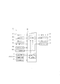
次に、図6のブロック線図を用いて、目標起伏角速度(起伏角速度目標値)に基づいて、起伏角速度制御信号を生成する際に、所定の帯域を減衰する帯域除去フィルタを適用する動作について説明する。まず、開始指令によって、第1制御信号生成部91は、ウインチ13の速度を一定の回転速度γdに維持するように制御対象であるクレーン93(ウインチモータ64)に指示する。このウインチ速度制御は、計測されたロープ長に基づいてフィードバック制御される。計測されたロープ長は、他方では、地切り判定に用いられることで、フィルタ適用部95の起動のトリガーとなる。
次に、図7のフローチャートを用いて、本実施形態の地切り制御の全体の流れについて説明する。
次に、図8のグラフを用いて、本実施形態の地切り判定の手法について説明する。本実施形態では、コントローラ40は、地切り制御においてウインチ13を巻き上げている途中に、計測された荷重の時系列データを監視しており、この時系列データの最初の極大値を捉えて地切りしたものと判定する。
上述の手法とは別に、本実施形態のコントローラ40は、地切り制御において、ウインチ13を巻上げて吊荷を地切りする際に、計測された荷重の時間変化と計測されたロープ長の時間変化に基づいて地切りを判定するように構成することもできる。
次に、本実施形態の地切り制御装置Dの奏する効果を列挙して説明する。
a 線形係数
1 ラフテレーンクレーン
10 車体
12 旋回台
13 ウインチ
14 ブーム
16 ワイヤロープ
17 フック
20A 地切りスイッチ
20B ウインチ速度設定手段
21 圧力計測器
22 回転数計測器
23 姿勢検出手段
231 起伏角度計
232 起伏角速度計
40 コントローラ
40a 選択機能部
40b 地切り判定機能部
51 旋回レバー
52 起伏レバー
53 伸縮レバー
54 ウインチレバー
61 旋回モータ
62 起伏シリンダ
63 伸縮シリンダ
64 ウインチモータ
91 第1制御信号生成部
92 第2制御信号生成部
93 クレーン(制御対象)
94 PID制御部
95 フィルタ適用部
Claims (8)
- ブーム、及び、ワイヤロープを巻上げるウインチを有するクレーンに搭載され、吊荷の地切り制御を行う地切り制御装置であって、
前記ブームに作用する荷重を検出する荷重検出部と、
前記ウインチの巻上げ動作及び前記ブームの起仰動作を制御する制御部と、を備え、
前記制御部は、前記荷重検出部の検出値の時間変化に基づいて生成され、且つ、所定範囲の周波数成分を減衰させるフィルタを適用した制御信号により、前記ブームの起仰を制御して前記吊荷の揺れを抑制する、
地切り制御装置。 - 前記フィルタは、前記ブームの長さ及び/又は前記ブームの伸縮パターンに応じた前記ブームの固有振動数を減衰させる周波数特性を有する、請求項1に記載の地切り制御装置。
- 前記制御部は、地切りが完了した後、前記制御信号に前記フィルタを適用して、前記起仰動作を停止させる、請求項1又は2に記載の地切り制御装置。
- 前記制御部は、前記荷重検出部の検出値における最初の極大値を検出した場合に、地切が完了したと判定する、請求項3に記載の地切り制御装置。
- 前記制御部は、前記地切り制御において、前記ウインチを定速で巻上げるように前記ウインチを制御する、請求項1~4の何れか一項に記載の地切り制御装置。
- 前記制御部は、
前記荷重の時間変化に基づいて前記ブームの起伏角度の変化量を算出し、
算出した前記変化量に応じた目標起伏角速度を算出し、
前記目標起伏角速度に基づいて前記制御信号を生成する、
請求項1~5の何れか一項に記載の地切り制御装置。 - 前記ブームの姿勢情報を検出する姿勢検出部を、更に備え、
前記制御部は、
前記姿勢情報の初期値及び前記荷重の初期値に基づいて対応する特性テーブル又は伝達関数を選択し、
前記特性テーブル又は前記伝達関数と前記荷重の時間変化とに基づいて、前記ブームの起伏角度の変化量を算出する、
請求項6に記載の地切り制御装置。 - 請求項1~7の何れか一項に記載の地切り制御装置を備える、クレーン。
Priority Applications (4)
| Application Number | Priority Date | Filing Date | Title |
|---|---|---|---|
| CN202180037921.3A CN115667122A (zh) | 2020-06-03 | 2021-06-03 | 吊离地面控制装置及起重机 |
| EP21817598.2A EP4163245B1 (en) | 2020-06-03 | 2021-06-03 | Dynamic lift-off control device, and crane |
| US18/007,597 US20230227290A1 (en) | 2020-06-03 | 2021-06-03 | Dynamic lift-off control device, and crane |
| JP2022528893A JP7323070B2 (ja) | 2020-06-03 | 2021-06-03 | 地切り制御装置、及び、クレーン |
Applications Claiming Priority (2)
| Application Number | Priority Date | Filing Date | Title |
|---|---|---|---|
| JP2020097023 | 2020-06-03 | ||
| JP2020-097023 | 2020-06-03 |
Publications (1)
| Publication Number | Publication Date |
|---|---|
| WO2021246490A1 true WO2021246490A1 (ja) | 2021-12-09 |
Family
ID=78831250
Family Applications (1)
| Application Number | Title | Priority Date | Filing Date |
|---|---|---|---|
| PCT/JP2021/021225 Ceased WO2021246490A1 (ja) | 2020-06-03 | 2021-06-03 | 地切り制御装置、及び、クレーン |
Country Status (5)
| Country | Link |
|---|---|
| US (1) | US20230227290A1 (ja) |
| EP (1) | EP4163245B1 (ja) |
| JP (1) | JP7323070B2 (ja) |
| CN (1) | CN115667122A (ja) |
| WO (1) | WO2021246490A1 (ja) |
Families Citing this family (3)
| Publication number | Priority date | Publication date | Assignee | Title |
|---|---|---|---|---|
| JP7485211B2 (ja) * | 2021-04-20 | 2024-05-16 | 株式会社タダノ | 巻層数の推定装置及びクレーン |
| CN117208759B (zh) * | 2023-09-28 | 2026-03-24 | 沈阳理工大学 | 塔吊、滤波器设计方法、计算机装置、可读存储介质 |
| CN117886241B (zh) * | 2024-03-14 | 2024-06-04 | 山东中建众力机械工程有限公司 | 基于振动分析的塔式起重机自检系统 |
Citations (6)
| Publication number | Priority date | Publication date | Assignee | Title |
|---|---|---|---|---|
| JPH01256496A (ja) * | 1988-04-04 | 1989-10-12 | Tadano Ltd | ブームを有するクレーンの吊荷地切時荷振防止装置 |
| JPH08188379A (ja) | 1995-01-10 | 1996-07-23 | Kobe Steel Ltd | クレーンの鉛直地切り制御装置 |
| JP2018087069A (ja) * | 2016-11-29 | 2018-06-07 | 株式会社タダノ | クレーン |
| JP2019001584A (ja) * | 2017-06-13 | 2019-01-10 | 株式会社タダノ | クレーン |
| WO2019167893A1 (ja) * | 2018-02-28 | 2019-09-06 | 株式会社タダノ | クレーン及び玉掛け具の長さ取得方法 |
| JP2020097023A (ja) | 2018-12-18 | 2020-06-25 | 三菱ケミカルアクア・ソリューションズ株式会社 | 排水の処理方法および排水の処理システム |
Family Cites Families (32)
| Publication number | Priority date | Publication date | Assignee | Title |
|---|---|---|---|---|
| US5282136A (en) * | 1990-03-30 | 1994-01-25 | Kabushiki Kaisha Kobe Seiko Sho | Vertical releasing control device of crane hanging load |
| JP3056915B2 (ja) * | 1993-06-21 | 2000-06-26 | 株式会社神戸製鋼所 | クレーンの鉛直地切り制御装置 |
| US5960969A (en) * | 1996-01-26 | 1999-10-05 | Habisohn; Chris Xavier | Method for damping load oscillations on a crane |
| US5908122A (en) * | 1996-02-29 | 1999-06-01 | Sandia Corporation | Sway control method and system for rotary cranes |
| EP1326798B1 (de) * | 2000-10-19 | 2006-04-05 | Liebherr-Werk Nenzing GmbH | Kran oder bagger zum umschlagen von einer an einem lastseil hängenden last mit lastpendelungsdämpfung |
| US7426423B2 (en) * | 2003-05-30 | 2008-09-16 | Liebherr-Werk Nenzing—GmbH | Crane or excavator for handling a cable-suspended load provided with optimised motion guidance |
| CN100425520C (zh) * | 2003-08-05 | 2008-10-15 | 新东工业株式会社 | 起重机及其控制器 |
| US7289875B2 (en) * | 2003-11-14 | 2007-10-30 | Siemens Technology-To-Business Center Llc | Systems and methods for sway control |
| US7341158B2 (en) * | 2004-01-09 | 2008-03-11 | Kobelco Cranes Co., Ltd. | Traveling crane and assembling/disassembling method thereof |
| DE102006048988A1 (de) * | 2006-10-17 | 2008-04-24 | Liebherr-Werk Nenzing Gmbh, Nenzing | Steuerungssystem für einen Auslegerkran |
| US8491025B2 (en) * | 2007-02-13 | 2013-07-23 | Edw. C. Levy Co. | Magnet controller for controlling a lifting magnet |
| JP5384813B2 (ja) * | 2007-09-10 | 2014-01-08 | 株式会社タダノ | 作業機の安全装置 |
| US8352129B2 (en) * | 2008-10-16 | 2013-01-08 | Eaton Corporation | Motion control of work vehicle |
| DE102009032269A1 (de) * | 2009-07-08 | 2011-01-13 | Liebherr-Werk Nenzing Gmbh | Kransteuerung zur Ansteuerung eines Hubwerkes eines Kranes |
| NO337712B1 (no) * | 2010-03-24 | 2016-06-06 | Nat Oilwell Varco Norway As | Anordning og fremgangsmåte for å redusere dynamiske laster i kraner |
| DE102011107754B4 (de) * | 2011-06-10 | 2021-07-22 | Liebherr-Werk Ehingen Gmbh | Winkelbezogenes Verfahren zur Überwachung der Kransicherheit während des Rüstvorgangs, sowie Kran und Kransteuerung |
| JP6147062B2 (ja) * | 2013-04-02 | 2017-06-14 | 株式会社タダノ | 作業機の作業状態確認装置 |
| JP6451271B2 (ja) * | 2014-12-09 | 2019-01-16 | 株式会社タダノ | 移動式クレーン |
| US10384915B2 (en) * | 2015-03-19 | 2019-08-20 | Tadano Ltd. | Pivoting device |
| JP6693842B2 (ja) * | 2016-09-08 | 2020-05-13 | 住友重機械建機クレーン株式会社 | クレーン |
| JP6684240B2 (ja) * | 2017-03-06 | 2020-04-22 | 日立建機株式会社 | 建設機械 |
| JP6834887B2 (ja) * | 2017-09-29 | 2021-02-24 | 株式会社タダノ | クレーン |
| CN108303883A (zh) * | 2018-01-22 | 2018-07-20 | 五邑大学 | 基于一阶动态滑模变结构的桥吊防摆方法 |
| JP6956645B2 (ja) * | 2018-02-06 | 2021-11-02 | 住友重機械建機クレーン株式会社 | 吊荷重演算装置 |
| JP7172206B2 (ja) * | 2018-07-10 | 2022-11-16 | 株式会社タダノ | クレーン |
| JP7484731B2 (ja) * | 2019-02-14 | 2024-05-16 | 株式会社タダノ | 地切り制御装置及びクレーン |
| US20220098009A1 (en) * | 2019-02-14 | 2022-03-31 | Tadano Ltd. | Lifting control device and mobile crane |
| JP7126981B2 (ja) * | 2019-03-29 | 2022-08-29 | 住友重機械建機クレーン株式会社 | クレーン |
| US12422790B2 (en) * | 2019-10-11 | 2025-09-23 | Tadano Ltd. | Control system, and crane |
| EP4163244A4 (en) * | 2020-06-03 | 2024-06-19 | Tadano Ltd. | DYNAMIC LIFT AND CRANE CONTROL DEVICE |
| JP7517071B2 (ja) * | 2020-10-21 | 2024-07-17 | 株式会社タダノ | クレーン、クレーンの特性変化判定装置、及びクレーンの特性変化判定システム |
| CN116964283A (zh) * | 2021-09-30 | 2023-10-27 | 日立建机株式会社 | 作业机械 |
-
2021
- 2021-06-03 WO PCT/JP2021/021225 patent/WO2021246490A1/ja not_active Ceased
- 2021-06-03 CN CN202180037921.3A patent/CN115667122A/zh active Pending
- 2021-06-03 JP JP2022528893A patent/JP7323070B2/ja active Active
- 2021-06-03 EP EP21817598.2A patent/EP4163245B1/en active Active
- 2021-06-03 US US18/007,597 patent/US20230227290A1/en active Pending
Patent Citations (6)
| Publication number | Priority date | Publication date | Assignee | Title |
|---|---|---|---|---|
| JPH01256496A (ja) * | 1988-04-04 | 1989-10-12 | Tadano Ltd | ブームを有するクレーンの吊荷地切時荷振防止装置 |
| JPH08188379A (ja) | 1995-01-10 | 1996-07-23 | Kobe Steel Ltd | クレーンの鉛直地切り制御装置 |
| JP2018087069A (ja) * | 2016-11-29 | 2018-06-07 | 株式会社タダノ | クレーン |
| JP2019001584A (ja) * | 2017-06-13 | 2019-01-10 | 株式会社タダノ | クレーン |
| WO2019167893A1 (ja) * | 2018-02-28 | 2019-09-06 | 株式会社タダノ | クレーン及び玉掛け具の長さ取得方法 |
| JP2020097023A (ja) | 2018-12-18 | 2020-06-25 | 三菱ケミカルアクア・ソリューションズ株式会社 | 排水の処理方法および排水の処理システム |
Non-Patent Citations (1)
| Title |
|---|
| See also references of EP4163245A4 |
Also Published As
| Publication number | Publication date |
|---|---|
| EP4163245A1 (en) | 2023-04-12 |
| JP7323070B2 (ja) | 2023-08-08 |
| EP4163245B1 (en) | 2025-08-06 |
| JPWO2021246490A1 (ja) | 2021-12-09 |
| CN115667122A (zh) | 2023-01-31 |
| EP4163245A4 (en) | 2024-06-26 |
| US20230227290A1 (en) | 2023-07-20 |
Similar Documents
| Publication | Publication Date | Title |
|---|---|---|
| JPWO2020166721A1 (ja) | 地切り制御装置及びクレーン | |
| WO2021246490A1 (ja) | 地切り制御装置、及び、クレーン | |
| JP6822603B2 (ja) | クレーン | |
| JPWO2020166690A1 (ja) | 地切り制御装置、及び移動式クレーン | |
| JPH0710469A (ja) | クレーンの鉛直地切り制御装置 | |
| WO2021246491A1 (ja) | 地切り制御装置、及び、クレーン | |
| CN110709348B (zh) | 起重机 | |
| CN111836774B (zh) | 起重机及起重机的控制方法 | |
| JPWO2021246490A5 (ja) | ||
| WO2021060463A1 (ja) | 制御システム及び作業機 | |
| JPWO2020166688A1 (ja) | 地切り判定装置、地切り制御装置、移動式クレーン、及び、地切り判定方法 | |
| WO2020166689A1 (ja) | 地切り判定装置、地切り制御装置、及び移動式クレーン | |
| JP2021187653A (ja) | 地切り制御装置、及び、移動式クレーン | |
| JP2026503624A (ja) | 旋回式ジブクレーンを運転する方法及び装置、旋回式ジブクレーン、及び、プログラム | |
| JP7396495B2 (ja) | 地切り制御装置、及び、移動式クレーン | |
| JP2024167103A (ja) | 地切り制御装置、及び、移動式クレーン | |
| JP2011105429A (ja) | 可変ピッチプロペラを用いた振動制御装置 | |
| AU2024285844A1 (en) | A system and a method for handling a load in an elevated position | |
| WO2022050023A1 (ja) | クレーンの旋回振れ止め装置およびこれを備えたクレーン | |
| JP6565275B2 (ja) | アクチュエータの制御装置 |
Legal Events
| Date | Code | Title | Description |
|---|---|---|---|
| 121 | Ep: the epo has been informed by wipo that ep was designated in this application |
Ref document number: 21817598 Country of ref document: EP Kind code of ref document: A1 |
|
| ENP | Entry into the national phase |
Ref document number: 2022528893 Country of ref document: JP Kind code of ref document: A |
|
| NENP | Non-entry into the national phase |
Ref country code: DE |
|
| ENP | Entry into the national phase |
Ref document number: 2021817598 Country of ref document: EP Effective date: 20230103 |
|
| WWG | Wipo information: grant in national office |
Ref document number: 2021817598 Country of ref document: EP |