WO2021250878A1 - デマンド調停装置、車両、及びデマンド調停システム - Google Patents
デマンド調停装置、車両、及びデマンド調停システム Download PDFInfo
- Publication number
- WO2021250878A1 WO2021250878A1 PCT/JP2020/023133 JP2020023133W WO2021250878A1 WO 2021250878 A1 WO2021250878 A1 WO 2021250878A1 JP 2020023133 W JP2020023133 W JP 2020023133W WO 2021250878 A1 WO2021250878 A1 WO 2021250878A1
- Authority
- WO
- WIPO (PCT)
- Prior art keywords
- vehicle
- belonging
- unit
- demand arbitration
- demand
- Prior art date
- Legal status (The legal status is an assumption and is not a legal conclusion. Google has not performed a legal analysis and makes no representation as to the accuracy of the status listed.)
- Ceased
Links
Images





Classifications
-
- G—PHYSICS
- G01—MEASURING; TESTING
- G01C—MEASURING DISTANCES, LEVELS OR BEARINGS; SURVEYING; NAVIGATION; GYROSCOPIC INSTRUMENTS; PHOTOGRAMMETRY OR VIDEOGRAMMETRY
- G01C21/00—Navigation; Navigational instruments not provided for in groups G01C1/00 - G01C19/00
- G01C21/26—Navigation; Navigational instruments not provided for in groups G01C1/00 - G01C19/00 specially adapted for navigation in a road network
- G01C21/34—Route searching; Route guidance
- G01C21/3407—Route searching; Route guidance specially adapted for specific applications
-
- G—PHYSICS
- G08—SIGNALLING
- G08G—TRAFFIC CONTROL SYSTEMS
- G08G1/00—Traffic control systems for road vehicles
- G08G1/09—Arrangements for giving variable traffic instructions
- G08G1/0962—Arrangements for giving variable traffic instructions having an indicator mounted inside the vehicle, e.g. giving voice messages
- G08G1/0968—Systems involving transmission of navigation instructions to the vehicle
- G08G1/096805—Systems involving transmission of navigation instructions to the vehicle where the transmitted instructions are used to compute a route
- G08G1/096811—Systems involving transmission of navigation instructions to the vehicle where the transmitted instructions are used to compute a route where the route is computed offboard
- G08G1/096816—Systems involving transmission of navigation instructions to the vehicle where the transmitted instructions are used to compute a route where the route is computed offboard where the complete route is transmitted to the vehicle at once
-
- G—PHYSICS
- G01—MEASURING; TESTING
- G01C—MEASURING DISTANCES, LEVELS OR BEARINGS; SURVEYING; NAVIGATION; GYROSCOPIC INSTRUMENTS; PHOTOGRAMMETRY OR VIDEOGRAMMETRY
- G01C21/00—Navigation; Navigational instruments not provided for in groups G01C1/00 - G01C19/00
- G01C21/26—Navigation; Navigational instruments not provided for in groups G01C1/00 - G01C19/00 specially adapted for navigation in a road network
- G01C21/34—Route searching; Route guidance
- G01C21/3407—Route searching; Route guidance specially adapted for specific applications
- G01C21/3438—Rendezvous; Ride sharing
-
- G—PHYSICS
- G01—MEASURING; TESTING
- G01C—MEASURING DISTANCES, LEVELS OR BEARINGS; SURVEYING; NAVIGATION; GYROSCOPIC INSTRUMENTS; PHOTOGRAMMETRY OR VIDEOGRAMMETRY
- G01C21/00—Navigation; Navigational instruments not provided for in groups G01C1/00 - G01C19/00
- G01C21/26—Navigation; Navigational instruments not provided for in groups G01C1/00 - G01C19/00 specially adapted for navigation in a road network
- G01C21/34—Route searching; Route guidance
- G01C21/3453—Special cost functions, i.e. other than distance or default speed limit of road segments
- G01C21/3492—Special cost functions, i.e. other than distance or default speed limit of road segments employing speed data or traffic data, e.g. real-time or historical
-
- G—PHYSICS
- G01—MEASURING; TESTING
- G01C—MEASURING DISTANCES, LEVELS OR BEARINGS; SURVEYING; NAVIGATION; GYROSCOPIC INSTRUMENTS; PHOTOGRAMMETRY OR VIDEOGRAMMETRY
- G01C21/00—Navigation; Navigational instruments not provided for in groups G01C1/00 - G01C19/00
- G01C21/26—Navigation; Navigational instruments not provided for in groups G01C1/00 - G01C19/00 specially adapted for navigation in a road network
- G01C21/34—Route searching; Route guidance
- G01C21/36—Input/output arrangements for on-board computers
- G01C21/3691—Retrieval, searching and output of information related to real-time traffic, weather, or environmental conditions
-
- G—PHYSICS
- G06—COMPUTING OR CALCULATING; COUNTING
- G06Q—INFORMATION AND COMMUNICATION TECHNOLOGY [ICT] SPECIALLY ADAPTED FOR ADMINISTRATIVE, COMMERCIAL, FINANCIAL, MANAGERIAL OR SUPERVISORY PURPOSES; SYSTEMS OR METHODS SPECIALLY ADAPTED FOR ADMINISTRATIVE, COMMERCIAL, FINANCIAL, MANAGERIAL OR SUPERVISORY PURPOSES, NOT OTHERWISE PROVIDED FOR
- G06Q10/00—Administration; Management
- G06Q10/04—Forecasting or optimisation specially adapted for administrative or management purposes, e.g. linear programming or "cutting stock problem"
- G06Q10/047—Optimisation of routes or paths, e.g. travelling salesman problem
-
- G—PHYSICS
- G06—COMPUTING OR CALCULATING; COUNTING
- G06Q—INFORMATION AND COMMUNICATION TECHNOLOGY [ICT] SPECIALLY ADAPTED FOR ADMINISTRATIVE, COMMERCIAL, FINANCIAL, MANAGERIAL OR SUPERVISORY PURPOSES; SYSTEMS OR METHODS SPECIALLY ADAPTED FOR ADMINISTRATIVE, COMMERCIAL, FINANCIAL, MANAGERIAL OR SUPERVISORY PURPOSES, NOT OTHERWISE PROVIDED FOR
- G06Q10/00—Administration; Management
- G06Q10/06—Resources, workflows, human or project management; Enterprise or organisation planning; Enterprise or organisation modelling
- G06Q10/063—Operations research, analysis or management
- G06Q10/0631—Resource planning, allocation, distributing or scheduling for enterprises or organisations
-
- G—PHYSICS
- G06—COMPUTING OR CALCULATING; COUNTING
- G06Q—INFORMATION AND COMMUNICATION TECHNOLOGY [ICT] SPECIALLY ADAPTED FOR ADMINISTRATIVE, COMMERCIAL, FINANCIAL, MANAGERIAL OR SUPERVISORY PURPOSES; SYSTEMS OR METHODS SPECIALLY ADAPTED FOR ADMINISTRATIVE, COMMERCIAL, FINANCIAL, MANAGERIAL OR SUPERVISORY PURPOSES, NOT OTHERWISE PROVIDED FOR
- G06Q50/00—Information and communication technology [ICT] specially adapted for implementation of business processes of specific business sectors, e.g. utilities or tourism
- G06Q50/40—Business processes related to the transportation industry
-
- G—PHYSICS
- G08—SIGNALLING
- G08G—TRAFFIC CONTROL SYSTEMS
- G08G1/00—Traffic control systems for road vehicles
- G08G1/01—Detecting movement of traffic to be counted or controlled
- G08G1/0104—Measuring and analyzing of parameters relative to traffic conditions
- G08G1/0108—Measuring and analyzing of parameters relative to traffic conditions based on the source of data
- G08G1/0112—Measuring and analyzing of parameters relative to traffic conditions based on the source of data from the vehicle, e.g. floating car data [FCD]
-
- G—PHYSICS
- G08—SIGNALLING
- G08G—TRAFFIC CONTROL SYSTEMS
- G08G1/00—Traffic control systems for road vehicles
- G08G1/01—Detecting movement of traffic to be counted or controlled
- G08G1/0104—Measuring and analyzing of parameters relative to traffic conditions
- G08G1/0125—Traffic data processing
- G08G1/0133—Traffic data processing for classifying traffic situation
-
- G—PHYSICS
- G08—SIGNALLING
- G08G—TRAFFIC CONTROL SYSTEMS
- G08G1/00—Traffic control systems for road vehicles
- G08G1/01—Detecting movement of traffic to be counted or controlled
- G08G1/0104—Measuring and analyzing of parameters relative to traffic conditions
- G08G1/0137—Measuring and analyzing of parameters relative to traffic conditions for specific applications
- G08G1/0141—Measuring and analyzing of parameters relative to traffic conditions for specific applications for traffic information dissemination
-
- G—PHYSICS
- G08—SIGNALLING
- G08G—TRAFFIC CONTROL SYSTEMS
- G08G1/00—Traffic control systems for road vehicles
- G08G1/01—Detecting movement of traffic to be counted or controlled
- G08G1/0104—Measuring and analyzing of parameters relative to traffic conditions
- G08G1/0137—Measuring and analyzing of parameters relative to traffic conditions for specific applications
- G08G1/0145—Measuring and analyzing of parameters relative to traffic conditions for specific applications for active traffic flow control
-
- G—PHYSICS
- G08—SIGNALLING
- G08G—TRAFFIC CONTROL SYSTEMS
- G08G1/00—Traffic control systems for road vehicles
- G08G1/09—Arrangements for giving variable traffic instructions
- G08G1/0962—Arrangements for giving variable traffic instructions having an indicator mounted inside the vehicle, e.g. giving voice messages
- G08G1/0967—Systems involving transmission of highway information, e.g. weather, speed limits
- G08G1/096708—Systems involving transmission of highway information, e.g. weather, speed limits where the received information might be used to generate an automatic action on the vehicle control
-
- G—PHYSICS
- G08—SIGNALLING
- G08G—TRAFFIC CONTROL SYSTEMS
- G08G1/00—Traffic control systems for road vehicles
- G08G1/09—Arrangements for giving variable traffic instructions
- G08G1/0962—Arrangements for giving variable traffic instructions having an indicator mounted inside the vehicle, e.g. giving voice messages
- G08G1/0967—Systems involving transmission of highway information, e.g. weather, speed limits
- G08G1/096733—Systems involving transmission of highway information, e.g. weather, speed limits where a selection of the information might take place
- G08G1/096741—Systems involving transmission of highway information, e.g. weather, speed limits where a selection of the information might take place where the source of the transmitted information selects which information to transmit to each vehicle
-
- G—PHYSICS
- G08—SIGNALLING
- G08G—TRAFFIC CONTROL SYSTEMS
- G08G1/00—Traffic control systems for road vehicles
- G08G1/09—Arrangements for giving variable traffic instructions
- G08G1/0962—Arrangements for giving variable traffic instructions having an indicator mounted inside the vehicle, e.g. giving voice messages
- G08G1/0967—Systems involving transmission of highway information, e.g. weather, speed limits
- G08G1/096766—Systems involving transmission of highway information, e.g. weather, speed limits where the system is characterised by the origin of the information transmission
- G08G1/096775—Systems involving transmission of highway information, e.g. weather, speed limits where the system is characterised by the origin of the information transmission where the origin of the information is a central station
-
- G—PHYSICS
- G08—SIGNALLING
- G08G—TRAFFIC CONTROL SYSTEMS
- G08G1/00—Traffic control systems for road vehicles
- G08G1/09—Arrangements for giving variable traffic instructions
- G08G1/0962—Arrangements for giving variable traffic instructions having an indicator mounted inside the vehicle, e.g. giving voice messages
- G08G1/0968—Systems involving transmission of navigation instructions to the vehicle
- G08G1/096833—Systems involving transmission of navigation instructions to the vehicle where different aspects are considered when computing the route
- G08G1/096844—Systems involving transmission of navigation instructions to the vehicle where different aspects are considered when computing the route where the complete route is dynamically recomputed based on new data
-
- G—PHYSICS
- G08—SIGNALLING
- G08G—TRAFFIC CONTROL SYSTEMS
- G08G1/00—Traffic control systems for road vehicles
- G08G1/20—Monitoring the location of vehicles belonging to a group, e.g. fleet of vehicles, countable or determined number of vehicles
- G08G1/202—Dispatching vehicles on the basis of a location, e.g. taxi dispatching
-
- G—PHYSICS
- G08—SIGNALLING
- G08G—TRAFFIC CONTROL SYSTEMS
- G08G1/00—Traffic control systems for road vehicles
- G08G1/22—Platooning, i.e. convoy of communicating vehicles
Definitions
- the present application relates to a demand arbitration device, a vehicle, and a demand arbitration system.
- Patent Document 1 discloses a server that changes a destination and transmits a travel route to the destination in response to a request from a user in a vehicle.
- Patent Document 1 is a technique assuming that one vehicle travels to a destination independently, and does not consider a case where a vehicle group of a plurality of vehicles travels to a common destination.
- a travel route of each vehicle is individually generated. Therefore, the traveling routes set for each of the plurality of vehicles may be different from each other. Therefore, due to changes in the road conditions (traffic jams, etc.) and weather conditions of each vehicle, the arrival time of each vehicle at the destination tends to vary, and when trying to stop at a common drive-through, etc. on the way, Since the roads are different, it is difficult to stop at a common destination on the way smoothly.
- an object of the present application is to provide a demand arbitration device, a vehicle, and a demand arbitration system capable of suppressing the travel routes of each vehicle from being different from each other when a vehicle group of a plurality of vehicles travels to a common destination. And.
- the demand arbitration device is A communication unit that communicates with multiple vehicles, A group control unit that manages a vehicle group that groups multiple vehicles, A demand arbitration unit that sets a common destination for the vehicle group based on a request received from a vehicle belonging to the vehicle group.
- Each belonging vehicle belonging to the vehicle group is provided with a guidance route generation unit that generates a traveling route from the current position of each belonging vehicle to the common destination and transmits the traveling route to each belonging vehicle.
- the guidance route generation unit generates a travel route of each belonging vehicle so that the traveling routes of the belonging vehicles overlap each other.
- the vehicle according to the present application is A communication unit that communicates with the demand arbitration device that generates and transmits the travel route of each belonging vehicle belonging to the vehicle group,
- the demand arbitration device that generates and transmits the travel route of each belonging vehicle belonging to the vehicle group.
- the group setting unit to be transmitted to the demand arbitration device and
- a demand transmission unit that transmits the request to the demand arbitration device and a demand transmission unit.
- the demand arbitration device includes a travel route receiving unit that receives the travel route of the own vehicle among the vehicles belonging to the vehicle group and sets the received travel route as the travel route of the own vehicle. be.
- the demand arbitration system is With the above demand arbitration device, It is equipped with a plurality of the above-mentioned vehicles.
- the travel route of each affiliation vehicle is generated so that the travel route of each affiliation vehicle overlaps with each other. It is possible to reduce the difference in (traffic jam, etc.) and reduce the difference in arrival time of each belonging vehicle to the destination. Further, when a stop-off point occurs during traveling, it is easy to duplicate the travel route to the stop-off point of each belonging vehicle, and it is easy to align the arrival time to the stop-off point.
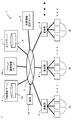
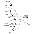
- FIG. It is a figure for demonstrating the generation of the traveling path which concerns on Embodiment 1.
- FIG. It is a schematic block diagram of the demand arbitration system which concerns on Embodiment 1.
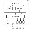
- FIG. It is a block diagram of the vehicle system which concerns on Embodiment 1.
- FIG. It is a hardware block diagram of the vehicle system which concerns on Embodiment 1.
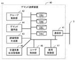
- FIG. It is a block diagram of the demand arbitration apparatus which concerns on Embodiment 1.
- FIG. It is a hardware block diagram of the demand arbitration apparatus which concerns on Embodiment 1.
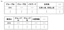
- FIG. It is a figure for demonstrating the data of the user database which concerns on Embodiment 1.
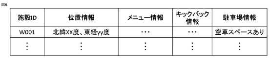
- FIG. It is a figure for demonstrating the data of the facility database which concerns on Embodiment 1.
- FIG. It is a figure for demonstrating the data of the group database which concerns on Embodiment 1.
- FIG. It is a figure for demonstrating the generation of the traveling path which concerns on Embodiment 1.
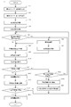
- FIG. It is a flowchart for demonstrating the processing procedure of the vehicle system which concerns on Embodiment 1.
- FIG. It is a figure for demonstrating the generation of the traveling path which concerns on Embodiment 2.
- the self-driving vehicle needs to change its travel route so as to go to the final destination via the facility.
- the traveling route may not always be the same even if the same destination is set.
- the left side of FIG. 1 shows a case where the same destination is input to three vehicles having the same current position, but different from the present embodiment, different traveling routes are set individually. If the plan is changed so that each vehicle stops at the same drive-through or other facility at some point while traveling on a different driving route, the arrival time of each vehicle greatly depends on the road conditions on which each vehicle is traveling. Will be done.
- the circle on the left side of FIG. 1 is the position of each vehicle at the time when the plan was changed to stop at the facility.
- the first vehicle 20A is caught in a traffic jam on the way and has a short mileage.
- the second vehicle 20B has good road conditions and has the longest mileage.
- the mileage of the third vehicle 20C is between the mileage of the first vehicle 20A and the mileage of the second vehicle 20B.
- the travel route and position of each vehicle at the time when the plan was changed are different, the travel route to the stop point of each vehicle is different for each vehicle, and the arrival time at the stop point is different for each vehicle.
- the third vehicle 20C has passed the stop point and then turned back toward the stop point. In this way, it is considered that the user's convenience is impaired when the vehicle waits for another vehicle at the stop-off point and turns back toward the stop-off point.
- the traveling route set for each of the plurality of vehicles may be different from each other.
- the traveling routes of the vehicles overlap each other. Is generated. Therefore, it is possible to reduce the difference in road conditions (traffic jam, etc.) affected by each vehicle while traveling to the destination, and reduce the difference in the arrival time of each vehicle to the destination.
- the circle on the right side of FIG. 1 indicates the position of each vehicle at the time when the plan was changed so as to stop by the facility, and the positions of the vehicles are almost the same. Therefore, it is easy to overlap the traveling routes from the circles of each vehicle to the stop-off point, and it is easy to align the arrival times at the stop-off points.
- FIG. 2 is a diagram showing a schematic overall configuration of the demand arbitration system 1.
- the demand arbitration system 1 includes a demand arbitration device 40 and a plurality of vehicles 20 to which a travel route is transmitted from the demand arbitration device 40.
- the demand arbitration system 1 includes a DM providing server 5, an edge server 7, and a weather information providing server 6.
- the demand arbitration device 40, the plurality of vehicles 20, the DM providing server 5, the edge server 7, and the weather information providing server 6 are communicably connected to each other via the network 3.
- the network network 3 is, for example, an internet network or a wireless communication network such as a wireless LAN (Local Area Network).
- a plurality of facilities 70 (restaurants and the like) are connected to the network network 3, and the demand arbitration device 40 communicates with each facility 70 according to the user's request to make a reservation for the facility or to make a menu. Or place an order for.
- the demand arbitration device 40 is provided in the server connected to the network network 3. That is, the function of the demand arbitration device 40 is realized by the server executing the application (program) of the demand arbitration device 40.
- the server is, for example, a cloud server.
- the network network 3 is, for example, a core network.
- the demand arbitration device 40 and the server may be set near the area to be controlled.
- the DM providing server 5 has a DM database 5a (for example, a hard disk) that holds a dynamic map that is dynamic road environment information necessary for realizing automatic driving of the vehicle 20.
- the DM providing server 5 periodically and repeatedly updates the dynamic map stored in the DM database 5a.
- the DM providing server 5 acquires dynamic map data from the DM database 5a and transmits it to the vehicle 20 or the demand arbitration device 40 each time in response to a periodic request from the vehicle 20 or the demand arbitration device 40.
- the dynamic map is, for example, a combination of static, high-precision three-dimensional map data and information on positions where dynamic changes such as road congestion information, traffic restrictions due to accidents or road construction have occurred. It is digital map data.
- the vehicle 20 has a peripheral area based on the detection output of a sensor (for example, a millimeter wave radar, an ultrasonic sensor, an optical camera, etc.) mounted on the vehicle. Automatic operation can be performed while accurately estimating environmental information.
- the edge server 7 is appropriately (for example, a plurality of units) for determining the state of the real-time road environment on which the vehicle 20 travels (for example, detection and collection of dynamic changes such as the above-mentioned traffic jam, accident, or road construction). Be placed.
- the edge server 7 has, for example, a sensor detection information database 7a in which a plurality of monitoring sensors are connected to one edge server 7 and holds information (sensor detection information) detected by the plurality of monitoring sensors.
- the plurality of monitoring sensors are arranged on, for example, utility poles on roads, poles or guardrails on highways, etc., in order to detect real-time road environmental conditions.
- the edge server 7 determines that, for example, a traffic jam, an accident, or road construction has occurred on a road based on sensor detection information detected by a plurality of monitoring sensors, and provides DM of road information including information on the position of the occurrence. It is transmitted to the server 5 and the vehicle 20. This road information is used, for example, when updating the dynamic map on the DM providing server 5.
- the weather information providing server 6 constantly collects and updates weather information such as weather, temperature, and humidity, and meets the weather each time in response to periodic requests from the vehicle 20 and the demand arbitration device 40. Information is transmitted to the vehicle 20 and the demand arbitration device 40.
- Each vehicle 20 is connected to a nearby base station 4 by wireless communication.
- a plurality of base stations 4 are dispersedly provided at each point so as to cover the road network.
- the base station 4 is a wireless station that wirelessly communicates with a vehicle system 25 mounted on a vehicle existing in a communication range by using a cellular wireless communication standard such as 4G or 5G, and is connected to a network network 3. ing. Therefore, each vehicle 20 and the demand arbitration device 40 are communicated and connected via the base station 4 and the network network 3.
- FIG. 3 shows a schematic configuration of a vehicle system 25 mounted on each vehicle 20.
- the vehicle system 25 includes a communication unit 26, a group setting unit 27, a demand transmission unit 28, and a travel route reception unit 29.
- the vehicle system 25 includes an environment recognition unit 30, a target travel track generation unit 31, and an automatic driving control unit 32 for automatic driving. Further, the vehicle system 25 includes a user input unit 35, sensors S1 to Sm (m is an integer of 2 or more), and a vehicle drive device 36.
- the vehicle system 25 includes an arithmetic processing unit 90, a storage device 91, an input / output device 92 for inputting / outputting an external signal to the arithmetic processing unit 90, and the like.
- CPU Central Processing Unit
- ASIC Application Specific Integrated Circuit
- IC Integrated Circuit
- DSP Digital Signal Processor
- FPGA Field Programmable Gate Array
- GPU Graphics Processing Unit
- AI Artificial Intelligence
- RAM RandomAccessMemory
- ROM ReadOnlyMemory
- flash memory EEPROM (ElectricallyErasableProgrammableReadOnlyMemory)
- hard disk a hard disk
- DVD device a DVD device
- the input / output device 92 is provided with a communication device, an A / D converter, a drive circuit, and the like.
- a user input unit 35, sensors S1 to Sm, a communication unit 26 (wireless communication device), a vehicle drive device 36, and the like are connected to the input / output device 92.
- the vehicle system 25 may be configured by a single control unit or may be configured by being distributed by a plurality of control units.
- the vehicle system 25 operates according to the program and data stored in the storage device 91.
- the target driving track generation unit 31 travels along the traveling route of the own vehicle received from the demand arbitration device 40 by the traveling route receiving unit 29 in consideration of the traveling information around the own vehicle recognized by the environment recognition unit 30.
- the automatic driving control unit 32 controls the vehicle driving device 36 to automatically drive the own vehicle along the target traveling track.
- the automatic driving of the vehicle 20 takes into consideration the distance from obstacles (for example, other vehicles, two-wheeled vehicles such as motorcycles, pedestrians, guardrails, utility poles, poles, facilities), and speeds in advance so that the vehicle can stop safely without collision. Includes the function of dropping the vehicle and stopping the vehicle 20. Further, the automatic driving of the vehicle 20 includes a function of following the vehicle 20 in front of the vehicle 20 while maintaining a certain distance from the other vehicle. Further, the automatic driving of the vehicle 20 includes a function of controlling the steering of the vehicle 20 so as not to go out of the lane, but each of the above-mentioned functions is an example of automatic driving and is not limited to these functions.
- obstacles for example, other vehicles, two-wheeled vehicles such as motorcycles, pedestrians, guardrails, utility poles, poles, facilities
- speeds in advance so that the vehicle can stop safely without collision. Includes the function of dropping the vehicle and stopping the vehicle 20.
- the automatic driving of the vehicle 20 includes a function of following the vehicle 20 in front of the vehicle 20
- the user input unit 35 is a device capable of inputting various data or information by a vehicle user (for example, a driver or a passenger of the vehicle 20), and is, for example, an HMI (Human Machine Interface) mounted in the vehicle 20. Accepts user operations on the displayed destination setting screen.
- the user input unit 35 outputs the information input by the user (for example, destination information, vehicle group setting information) to the vehicle system 25.
- the user input unit 35 may be an information terminal device such as a smartphone or tablet PC owned by the user.
- the user input unit 35 is connected to the group setting unit 27, and a vehicle group can be created and a vehicle group can be joined on the group setting screen.
- the group name, the vehicle ID registered in the vehicle group, the common destination, the password (which does not need to be set) and the like are input, and the vehicle group is created.
- Input of group information is a part and is not limited to this.
- the group setting unit 27 transmits the vehicle group information to the demand arbitration device 40 via the communication unit 26.
- Vehicle group information (group name, vehicle ID registered in the group, password, etc.) is stored in the group database DBc of the demand arbitration device 40.
- the group setting unit 27 transmits the group name to the demand arbitration device 40.
- Vehicle group candidates are sent from the demand arbitration device 40.
- the vehicle user selects a vehicle group in which the own vehicle participates from the candidates. If a password has been set, prompt the user to enter the password.
- the vehicle group selection information is transmitted to the demand arbitration device 40 via the communication unit 26, and the demand arbitration device 40 stores the vehicle ID in the group database DBc in order to register the vehicle in the vehicle group.
- the demand transmission unit 28 transmits a request related to the setting of a common destination of the vehicle group, which is set by the user of the own vehicle via the user input unit 35, to the demand arbitration device 40 via the communication unit 26. ..
- the HMI has a facility proposed by the demand arbitration device 40 (for example, a facility where the vehicle 20 can stop by) based on the user's operation, which will be described in detail later. (There are convenience stores, restaurants, drive-throughs, service areas, etc.) selection screens are displayed. In this case, a user operation (for example, an approval operation for approving the proposed facility) is input to the facility selection screen in the user input unit 35.
- a user operation for example, an approval operation for approving the proposed facility
- the sensors S1 to Sm are provided in the vehicle 20 in order to detect the environment around the vehicle 20, and the information detected by the respective sensors S1 to Sm is output to the environment recognition unit 30.
- the sensors S1 to Sm include, for example, a GPS receiver (Global Positioning System), an in-vehicle camera, an around view camera, a radar, and a laser range finder.
- the GPS receiver receives a plurality of signals indicating the time transmitted from the plurality of GPS satellites and the position (coordinates) of each GPS satellite, and based on the received plurality of signals, the GPS receiver is the vehicle 20.
- the position information of is output to the vehicle system 25.
- the in-vehicle camera is a camera having an image sensor such as a CCD (Charge Coupled Device) or a CMOS (Complementary Metal Oxide Semiconductor).
- the camera is installed in the center of the front part of the vehicle body of the vehicle 20, for example, and captures an image in the center of the front as a detection range.
- the camera detects obstacles and traffic lights existing in front of the own vehicle.
- the camera can perform image processing using the data of the captured image, and information indicating the relationship between the obstacle detected by the image processing and the own vehicle (for example, the speed of the obstacle with respect to the own vehicle and the like). It can detect the position information), the position and size of the traffic light, and the color of the signal light.
- the around view camera detects a white line in the vicinity of the vehicle 20 and other vehicles in the adjacent lane.
- the radar is configured by using a plurality of (for example, two) radars installed in the front of the vehicle body and the rear of the vehicle body of the vehicle 20 respectively.
- the radar may be installed only in front of the vehicle body of the vehicle 20.
- the radar is configured by using, for example, a millimeter wave radar, a sonar radar, and a lidar (LiDAR: Light Detection And Ringing, Laser Imaging Detection And Ringing).
- the radar irradiates electromagnetic waves such as ultrasonic waves or millimeter waves while scanning them in a limited angle range, receives the reflected light, and detects the time difference between the start time of irradiation and the reception time of the reflected light. It detects the distance between the own vehicle and the obstacle, and the direction of the obstacle as seen from the own vehicle.
- the laser range finder is installed on the front right side of the vehicle body, the front left side of the vehicle body, the right side of the vehicle body, the left side of the vehicle body, the right side of the rear of the vehicle body, and the left side of the rear of the vehicle body, respectively.
- the laser range finder detects obstacles and the like existing on the front right side, the front left side, the side right side, the side left side, the rear right side, and the rear left side of the vehicle 20, respectively.
- the laser range finder irradiates the laser light while scanning it in a fixed wide angle range, receives the reflected light, and detects the time difference between the start time of the irradiation and the light receiving time of the reflected light. By doing so, the distance between the own vehicle and the obstacle, and the direction of the obstacle as seen from the own vehicle are detected.
- the sensors constituting the sensors S1 to Sm are not limited to the above-mentioned in-vehicle camera, around view camera, radar, and laser range finder, and are, for example, a gyro sensor, an acceleration sensor, a geomagnetic sensor, an inclination sensor, a temperature sensor, and a pressure sensor.
- a humidity sensor and an illuminance sensor may be included.
- the communication unit 26 is composed of a wireless communication device that performs wireless communication using a cellular standard such as 4G or 5G.
- the communication unit 26 is connected to an external device (demand arbitration device 40, DM providing server 5, edge server 7, and weather information providing server 6) via the base station 4 and the network network 3.
- the communication unit 26 transmits the data and information transmitted from the external device to each part of the vehicle system 25, and transmits the data and information transmitted from each part of the vehicle system 25 to the external device.
- the communication unit 26 (wireless communication device) may be a mobile communication device such as a smartphone owned by the user.
- the travel route receiving unit 29 receives from the demand arbitration device 40 the travel route of the own vehicle among the vehicles belonging to the vehicle group via the communication unit 26, and the received travel route is the travel route of the own vehicle.
- the travel route transmitted from the demand arbitration device 40 is composed of information on a plurality of nodes to a common destination, a target time passing through each node, and the like.
- the group setting unit 27 sets a vehicle group in which a plurality of vehicles including the own vehicle are grouped by the user of the own vehicle via the user input unit 35, or participates in an existing vehicle group.
- the information of the user's setting or participation request is transmitted to the demand arbitration device 40 via the communication unit 26.
- the demand transmission unit 28 transmits a request related to the setting of a common destination of the vehicle group, which is set by the user of the own vehicle via the user input unit 35, to the demand arbitration device 40 via the communication unit 26. ..
- the environment recognition unit 30 recognizes environmental information around the own vehicle including the current position of the own vehicle based on the detection information of the plurality of sensors S1 to Sm, and outputs the recognition result to the target travel track generation unit 31. ..
- the target travel track generation unit 31 generates a target travel track that travels along the travel path of the own vehicle received from the demand arbitration device 40 in consideration of the surrounding environmental conditions.
- the target traveling track generation unit 31 includes a local track generation unit and a route evaluation unit.
- the local track generation unit provides road information and weather information corresponding to the position of the own vehicle acquired from the environment recognition unit 30 from the dynamic map data provided by the DM providing server 5 and the weather information providing server 6. Obtained from the weather information. Then, the local track generation unit has information on the surrounding environment (road information, weather information, other vehicles, etc.) regarding the local route in the predetermined distance section in front of the own vehicle among the traveling routes transmitted from the demand arbitration device 40. Obstacles, traffic information) will be taken into consideration to generate a target driving track that allows safe driving. Further, when it is necessary to bypass the travel route transmitted from the demand arbitration device 40, the local track generation unit generates a travel route and a target travel track that bypass the travel route.
- the target travel track is time-series data consisting of time, latitude, longitude, vehicle speed, and vehicle orientation (for example, the direction of the vehicle in the front-rear direction).
- the route evaluation unit objectively evaluates the suitability of the travel route transmitted from the demand arbitration device 40 according to a predetermined algorithm. Whether the route evaluation unit can arrive at the desired arrival time set by the user for the travel route of the demand arbitration device 40, for example, based on the traffic regulation on the route, the presence / absence of obstacles, and the prediction result of the arrival time. Evaluate whether or not, and calculate the score as the evaluation result. When the calculated score value becomes less than a predetermined threshold value, the route evaluation unit instructs the demand arbitration device 40 to regenerate the route.
- the automatic driving control unit 32 automatically drives the own vehicle along the target traveling track.
- the automatic driving control unit 32 has a command value of the driving force of the wheel, a command value of the braking force of the wheel, a command value of the steering angle of the wheel, a direction indicator, etc. for traveling the own vehicle along the target traveling track. Calculate the operation command value of the light of. Then, the automatic driving control unit 32 transmits each control command value to the vehicle driving device 36.
- the vehicle driving device 36 includes a power device, a braking device, a steering device, a light device, and the like.
- the power unit has a driving force source such as an internal combustion engine and an electric motor, and the driving force output from the driving force source is transmitted to the wheels.
- the power unit outputs a driving force according to a command value of the driving force.
- the braking device has an electric brake and generates a braking force according to a command value of the braking force.
- the steering device has an electric steering device, and changes the steering angle according to a command value of the steering angle.
- the light device has a direction indicator, a headlight, a brake lamp, and the like, and turns on each light according to an operation command value of the direction indicator and the like.
- the demand arbitration device 40 includes a communication unit 41, a group control unit 42, a guidance route generation unit 43, a demand arbitration unit 44, a traffic weather condition management unit 45, a user control unit 46, and a facility control unit 47. Etc. are provided.
- the demand arbitration device 40 includes an arithmetic processing unit 80, a storage device 81, an input / output device 82 for inputting / outputting an external signal to the arithmetic processing unit 80, and the like.
- the arithmetic processing device 80 is provided with a CPU, ASIC, IC, DSP, FPGA, GPU, AI chip, various logic circuits, various signal processing circuits, and the like. Further, the arithmetic processing unit 80 may be provided with a plurality of the same type or different types, and each processing may be shared and executed.
- the storage device 81 various storage devices such as RAM, ROM, flash memory, EEPROM, hard disk, and DVD device are used.
- the input / output device 82 is provided with a communication device or the like connected to the network network 3.
- the demand arbitration device 40 operates according to the program and data stored in the storage device 81.
- the communication unit 41 is mainly composed of the communication device of the input / output device 82.
- the communication unit 41 communicates with a plurality of vehicles 20, a DM providing server 5, an edge server 7, a weather information providing server 6, information terminal devices of a plurality of facilities 70, and the like via the network network 3.
- the traffic weather condition management unit 45 constantly receives the dynamic map data provided by the DM providing server 5 and the weather information provided by the weather information providing server 6 and stores them in the storage device 81.
- the traffic weather condition management unit 45 outputs the received dynamic map data and weather information to the guidance route generation unit 43.
- the user control unit 46 accesses the user database DBa stored in the storage device 81 and manages information (for example, extraction, new registration, update, deletion) regarding the vehicle and the user registered as the user of the demand arbitration system 1. Etc.).
- the facility control unit 47 accesses the facility database DBb stored in the storage device 81, and manages facility information corresponding to the information terminal devices 70 of a plurality of facilities communicably connected to the demand arbitration device 40. (For example, extraction, new registration, update, deletion, etc.).
- the user database DBa is configured by, for example, RDB (Relational Data Base), and holds information of a user registered as a user of the demand arbitration system 1.
- FIG. 7 is a diagram showing a structural example of user data registered in the user database DBa.
- the user database DBa stores user data configured by combining user information of one record for each user.
- the user information includes the visit date and time of the facility, the name of the visit facility, the order history, the preference information (that is, the information regarding the user's food preference), and the user feel stress for each user ID which is the identification information of the user. It is the information associated with the information of the allowable waiting time to the extent that there is no such thing. For example, according to the user information of the user ID "A001", the user likes “hamburgers, carbonated drinks, " and visited facility A on March 20, 2020 and ordered " ⁇ set". It is possible to find out. Further, according to the user information of the user ID "A001", it can be recognized that the user can wait "20 minutes” to receive the ordered food such as drive-through (that is, the possible waiting time).
- the facility database DBb is configured using, for example, an RDB, and holds information about a plurality of facilities registered as usage destinations of the demand arbitration system 1.
- FIG. 8 is a diagram showing a structural example of facility data registered in the facility database DBb.
- the facility database DBb stores facility data composed of a combination of facility information of one record for each facility.
- the facility information includes location information indicating the location of the facility for each facility ID, which is identification information of the facility, menu information of food (food and drink) that can be provided to customers such as users at the facility, and the facility as a kickback target. This is information that associates information about the selected food (food and drink) with parking lot information.
- the parking lot information indicates the availability of a parking lot owned by the facility or a parking lot that can be used by customers in cooperation with the owner or the like. The availability of the parking lot may be simply information indicating whether or not there is an empty car space, and may be not limited to that information but may be quantitative information indicating specifically how many empty car spaces are available.
- the facility information of the facility ID "W001” the facility is located at "north latitude xx degrees, east longitude yy degrees", and information on menus that can be provided at the facility, parking lot availability, etc. are shown. It is possible to find out the parking lot information and the information on the food (food and drink) to be kicked back.
- the group database DBc is stored in the storage device 81.
- the group database DBc is managed by the group control unit 42.
- the group database DBc is configured by using, for example, RDB, and holds information on the vehicle group.
- FIG. 9 is a diagram showing a structural example of group data registered in the group database DBc.
- the group database DBc stores group data composed of a combination of group information of one record for each group and vehicle data composed of a combination of group information of one record for each vehicle.
- the group information is information in which the group name, the password, and the destination information are associated with each group ID, which is the identification information of the vehicle group.
- the vehicle information is information in which the group ID and the group name are associated with each vehicle ID, which is the identification information of the vehicle.
- the route database DBd is stored in the storage device 81.
- the route database DBd stores the travel routes of each belonging vehicle generated by the guidance route generation unit 43, which will be described later, and is appropriately read out.
- the group control unit 42 manages a vehicle group in which a plurality of vehicles are grouped.
- the group control unit 42 sets the vehicle group based on a plurality of vehicle IDs included in the vehicle group setting information. Further, when a vehicle that does not belong to the vehicle group requests to join the vehicle group, the group control unit 42 additionally registers the requested vehicle in the vehicle group. If this additional registration is re-registered and a password is set for the vehicle group, password authentication may be performed.
- the group control unit 42 stores and manages the vehicle group information in the group database DBc described above.
- the demand arbitration unit 44 sets a common destination of the vehicle group based on the request received from the vehicle belonging to the vehicle group. For example, the demand arbitration unit 44 sets the destination received at the time of setting the first vehicle group as a common destination.
- the demand arbitration unit 44 sets the stop point to a common destination on the way when each belonging vehicle receives a request for a stop point from the belonging vehicle while traveling along the traveling route to a common destination. do.
- the demand arbitration unit 44 when the demand arbitration unit 44 receives the facility information as a request of the belonging vehicle (user), the demand arbitration unit 44 searches the map data (dynamic map in this example) for a facility that matches the received facility information. And set it to a common destination.
- the demand arbitration unit 44 receives the type of facility, the desired stop-by time, and the like as a request for the vehicle to which it belongs. For example, when the demand arbitration unit 44 receives a user's request "I want to go to a restaurant located within a travel distance of 30 minutes from the destination", the demand arbitration unit 44 searches for a restaurant that meets the request from the dynamic map. Send the searched multiple restaurants to the vehicle to which the request was made. Further, at this time, the demand arbitration unit 44 refers to the facility database DBb and uses the stored facility information.
- the vehicle system 25 (demand transmission unit 28) of the belonging vehicle presents the received information on the plurality of restaurants to the user via the user input unit 35, and causes the user to select one restaurant from the plurality of restaurants. ..
- the vehicle system 25 (demand transmission unit 28) transmits information on the restaurant selected by the user to the demand arbitration device 40 (demand arbitration unit 44).
- the demand arbitration unit 44 sets the received restaurant as a common destination on the way.
- the demand arbitration unit 44 may be configured to obtain the consent of other belonging vehicles belonging to the vehicle group when setting a common destination on the way. The process of searching for and selecting a facility that meets this requirement may be performed when setting the first common destination.
- the demand arbitration unit 44 determines the reservation time based on the scheduled arrival time at the facility, communicates with the facility, and makes a reservation for the facility at the reservation time. For example, when the user requests a facility reservation, the demand arbitration unit 44 obtains information on the estimated arrival time of each belonging vehicle from the traveling route of each belonging vehicle to the facility generated by the guidance route generation unit 43. Acquire and determine the reserved time based on the estimated arrival time of each belonging vehicle. For example, the demand arbitration unit 44 determines the reservation time according to the scheduled arrival time of the belonging vehicle arriving at the facility earliest or the latest, and makes a reservation for the facility at the reservation time.
- the demand arbitration unit 44 notifies the user to that effect, and causes the user to select the facility again, go to the facility without reservation, or cancel the request to go to the facility. , Performs processing according to the user's selection.
- the processing of reservations for this facility may be done when setting the first common destination.
- the demand arbitration unit 44 communicates with the restaurant based on the request of the user of the belonging vehicle, orders the menu, and plans the eating and drinking. Notify the arrival time at the store. For example, the demand arbitration unit 44 transmits the menu information to each belonging vehicle when the information on the menu of the restaurant set at the destination can be acquired and the order can be placed in advance.
- the vehicle system 25 (demand transmission unit 28) of the belonging vehicle causes the user to present the received menu information via the user input unit 35 and select the menu to be ordered.
- the vehicle system 25 (demand transmission unit 28) transmits information on the menu selected by the user to the demand arbitration device 40 (demand arbitration unit 44).
- the demand arbitration unit 44 transmits the information of the selection menu received from each belonging vehicle to the restaurant, places an order, and informs the scheduled arrival time. At this time, the demand arbitration unit 44 may make a reservation for the restaurant at the scheduled arrival time.
- the guidance route generation unit 43 generates a travel route from the current position of each belonging vehicle to a common destination for each belonging vehicle belonging to the vehicle group, and transmits the traveling route to each belonging vehicle. At this time, the guidance route generation unit 43 generates the travel route of each belonging vehicle so that the traveling route of each belonging vehicle overlaps with each other.
- the travel routes of the vehicles belonging to each affiliation are generated so that the travel routes of the vehicles belonging to each affiliation overlap with each other. It is possible to reduce the difference in arrival time of each belonging vehicle to the destination. Further, when a stop-off point occurs during traveling, it is easy to duplicate the travel route to the stop-off point of each belonging vehicle, and it is easy to align the arrival time to the stop-off point.
- the guidance route generation unit 43 When the current positions of the vehicles belonging to each affiliation are the same, the guidance route generation unit 43 generates the traveling routes of the vehicles belonging to each affiliation so that all the traveling routes of the vehicles belonging to each affiliation overlap with each other. For example, the guidance route generation unit 43 sets one belonging vehicle as a representative vehicle, generates a traveling route from the current position of the representative vehicle to a common destination, and generates a traveling route of the representative vehicle for the other belonging vehicles. Generates a travel route that travels on the same route (eg, node) as.
- the guidance route generation unit 43 When the current position of each belonging vehicle is different, the guidance route generation unit 43 generates a traveling route of each belonging vehicle so that the traveling routes of the belonging vehicles overlap each other at least in front of the common destination. do. For example, the guidance route generation unit 43 sets one belonging vehicle as a representative vehicle, and generates a travel route from the current position to a common destination for the representative vehicle.
- the representative vehicle may be set to the affiliation vehicle that first created the vehicle group, may be set to the affiliation vehicle that requested the setting of a common destination, and may be set to the affiliation vehicle randomly determined using random numbers or the like. May be done. Then, the guidance route generation unit 43 generates a travel route for each of the other belonging vehicles so that the route (node) overlaps with the travel route of the representative vehicle as much as possible.
- the guidance route generation unit 43 generates a travel route from the current position of another belonging vehicle to each point of the travel route of the representative vehicle, and determines a point where the evaluation point of the travel route to each point is the best.
- the evaluation points are calculated based on the length of the traveling route, the traveling time, the presence or absence of reverse driving, and the like.
- the difference between the arrival time of the other belonging vehicle to the destination and the arrival time of the representative vehicle to the destination when the travel route to each point is used is It may be evaluated. The smaller the difference in arrival time, the better the evaluation score.
- the guidance route generation unit 43 includes a route portion from a common destination in the travel route of the representative vehicle to the point having the best evaluation point, and a travel route from the point having the best evaluation point to the current position of another belonging vehicle. And are set as the travel route of the other belonging vehicle.
- the end point of the traveling route of the representative vehicle from the current position of the other belonging vehicle that is, that is.
- the evaluation point of the travel route to the common destination is the best, and the travel route of another belonging vehicle that does not overlap with the travel route of the representative vehicle may be set.
- the first vehicle 20A is set as the representative vehicle. For each node of the traveling route of the first vehicle 20A (plural nodes Nd1 to Nd8), a traveling route from the current position of the second vehicle 20B to each node of the traveling route of the representative vehicle is generated, and the traveling route to each node is generated. The node with the best evaluation score is determined. In the example of FIG. 10, the travel route to the third node Nd3 has the shortest travel route length and travel time, and the third node Nd3 has the best evaluation point.
- the traveling route of the second vehicle 20B is the route portion from the destination (8th node Nd8) to the 3rd node Nd3 in the traveling route of the 1st vehicle 20A and the current position of the 3rd node Nd3 to the 2nd vehicle 20B. It is set to the travel route up to.
- the guidance route generation unit 43 generates a travel route to a common destination of each belonging vehicle in consideration of road conditions, weather conditions, etc. of the dynamic map.
- the travel route includes information on a plurality of nodes to a common destination and a target time for passing each node.
- the guidance route generation unit 43 transmits the generated travel route of each belonging vehicle to each belonging vehicle via the communication unit 41. Further, the guidance route generation unit 43 stores the generated travel route of each belonging vehicle in the route database DBd.
- the guidance route generation unit 43 considers the road condition, the weather condition, etc., and the common destination of each belonging vehicle. You may regenerate the travel route up to and send it to each belonging vehicle.
- the guidance route generation unit 43 generates a travel route of each belonging vehicle so that the arrival time of the common destination of each belonging vehicle falls within the allowable time difference range. According to this configuration, it is possible to suppress that the waiting time of the belonging vehicle arriving earlier becomes larger than the allowable time difference, and it is possible to improve the convenience of the user. It should be noted that the presence / absence of the allowable time difference and the set value of the allowable time difference may be configured so that the user of the belonging vehicle can set it.
- the guidance route generation unit 43 increases or decreases the traveling speed of each belonging vehicle and expands or contracts the traveling route of each belonging vehicle so that the arrival time of each belonging vehicle falls within the allowable time difference range.
- the guidance route generation unit 43 determines each belonging vehicle so that the traveling routes of the belonging vehicles overlap with each other. Generates a travel route from the current position of the vehicle to a common destination on the way, and sends it to each belonging vehicle. The generation of the travel route to the common destination on the way is performed in the same manner as the generation of the travel route to the first common destination described above, and thus the description thereof will be omitted. Further, the guidance route generation unit 43 generates a travel route from a common destination on the way to the final common destination so that the travel routes of the vehicles belonging to each belong to each other, and the traveling routes are generated for each belonging vehicle. Send. A common destination on the way may be set, and a traveling route to stop in order may be set.
- the environment recognition unit 30 constantly recognizes environmental information around the own vehicle, including the current position of the own vehicle, based on the detection information of the plurality of sensors S1 to Sm, and outputs the recognized information to each part of the vehicle system 25. is doing.
- step St1 the group setting unit 27 receives the vehicle group setting by the operation of the user of the own vehicle via the user input unit 35 (for example, HMI).
- the demand transmission unit 28 receives the setting of a common destination of the vehicle group by the operation of the user of the own vehicle via the user input unit 35 (for example, HMI).
- step St2 the group setting unit 27 and the demand transmission unit 28 transmit the created vehicle group information and the common destination information to the demand arbitration device 40 via the communication unit 26.
- the demand arbitration device 40 generates a travel route of each belonging vehicle based on the received information and transmits it to each belonging vehicle.
- step St3 the travel route receiving unit 29 receives the travel route of the own vehicle transmitted from the demand arbitration device 40 via the communication unit 26, as described above. Then, in step St4, the travel route receiving unit 29 causes the user to select whether or not to approve the automatic driving along the received new travel route via the user input unit 35, and if approved, the user inputs.
- the received travel route is set as a new travel route of the own vehicle, and the automatic driving process is started.
- step St5 the demand transmission unit 28 makes a request related to the setting of a common destination of the vehicle group (for example, the setting of a stop-by point) via the user input unit 35 by the user of the own vehicle during automatic driving. It is determined whether or not the request has been made, and if the request is made, the process proceeds to step St6, and if the request is not made, the process proceeds to step St8.
- step St6 the demand transmission unit 28 transmits the user's request to the demand arbitration device 40.
- the demand arbitration device 40 When the vehicle system 25 requests the setting of a destination, the demand arbitration device 40 generates a travel route to a new common destination of each belonging vehicle and transmits the traveling route to each belonging vehicle. ..
- step St7 the travel route receiving unit 29 receives the travel route of the own vehicle transmitted from the demand arbitration device 40. Then, the travel route receiving unit 29 causes the user to select whether or not to approve the automatic driving along the received new travel route via the user input unit 35, and if approved, the received travel route. Is set as a new driving route for the own vehicle.
- step St8 the target travel track generation unit 31 generates a target travel track that travels along the travel path of the own vehicle received from the demand arbitration device 40 in consideration of the surrounding environmental conditions. Then, in step St9, the automatic driving control unit 32 automatically drives the own vehicle along the target traveling track as described above.
- step St10 the environment recognition unit 30 acquires information on the current position of the own vehicle based on the signal of the GPS receiver. As described above, the environment recognition unit 30 is constantly acquiring information on the current position, not only at the time of step St10.
- step St11 the target traveling track generation unit 31 determines whether or not the vehicle has arrived at the destination, and if it is determined that the vehicle has not arrived, the process proceeds to step St12. If it is determined that the vehicle has arrived, the vehicle proceeds to step St15. .. If the vehicle arrives at a common destination, it is determined that the vehicle is not in automatic operation.
- step St12 the travel route receiving unit 29 confirms whether or not a new travel route of the own vehicle is transmitted from the demand arbitration device 40, and if it is transmitted, proceeds to step St6 and is not transmitted. If so, the process proceeds to step St13.
- the transmission of a new travel route is performed when there is a request for a stop-off point for another vehicle belonging to the vehicle, or when there is a change in road conditions or weather conditions.
- step St13 the target travel track generation unit 31 estimates the estimated arrival time to arrive at a common destination from the current position of the own vehicle.
- step St14 the target travel track generation unit 31 transmits information on the estimated arrival time and information on the current position of the own vehicle to the demand arbitration device 40, and then returns to step St5.
- step St15 the target travel track generation unit 31 ends the generation of the target travel track and ends the automatic operation. Then, in step S16, the target travel track generation unit 31 transmits to the demand arbitration device 40 that it has arrived at a common destination via the communication unit 41.
- step St17 the target traveling track generation unit 31 determines whether or not the vehicle has arrived at the final common destination based on the information on the current position of the own vehicle, and if it is determined that the vehicle has arrived, step St18. If it is determined that the vehicle has not arrived, the process returns to step St5. At step St18, the vehicle system 25 ends the automatic driving according to the instruction of the demand arbitration device 40.
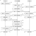
- step St40 the user (passenger) of the first vehicle has performed an operation of registering the vehicle group and setting the destination via the user input unit 35, so that the first vehicle (group setting of the vehicle system 25) is set.
- the unit 27 and the demand transmission unit 28) transmit the vehicle group setting information and the destination setting information input by the user to the demand arbitration device 40.
- step St41 the demand arbitration device 40 (group control unit 42) registers the vehicle group based on the vehicle group information received from the first vehicle, and stores the vehicle group information in the group database DBc.
- the demand arbitration device 40 (demand arbitration unit 44) sets a common destination of the vehicle group based on the destination information received from the first vehicle, and stores the common destination information in the group database DBc. ..
- step St42 an operation in which a user of the second vehicle not registered in the vehicle group searches based on the group name or the like via the user input unit 35 and requests participation in the vehicle group registered by the first vehicle.
- the second vehicle (group setting unit 27) transmits a request for participation in the vehicle group registered by the first vehicle to the demand arbitration device 40.
- the second vehicle (group setting unit 27) causes the user of the second vehicle to input the password via the user input unit 35 to perform authentication.
- step St43 the demand arbitration device 40 (group control unit 42) additionally registers the second vehicle in the vehicle group, and saves the changed vehicle group information in the group database DBc. Then, in step St44, the demand arbitration device 40 (group control unit 42) transmits the changed vehicle group information to each belonging vehicle of the vehicle group. In step St45, the group setting unit 27 of the first vehicle and the second vehicle each receives the vehicle group information transmitted from the demand arbitration device 40 and stores it in the storage device 91.
- step St46 the demand arbitration device 40 (guidance route generation unit 43) has a common destination for each belonging vehicle (in this example, the first vehicle and the second vehicle) belonging to the vehicle group from the current position of each belonging vehicle.
- the travel route up to is generated and transmitted to each belonging vehicle, and the traveling route of each belonging vehicle is saved in the route database DBd.
- the demand arbitration device 40 (guidance route generation unit 43) generates a travel route of each belonging vehicle so that the traveling routes of the belonging vehicles overlap each other.
- step St47 the travel route receiving units 29 of the first vehicle and the second vehicle each receive the travel route of their own vehicle transmitted from the demand arbitration device 40. Then, the target travel track generation unit 31 of the first vehicle and the second vehicle, respectively, considers the environmental conditions around the own vehicle and travels along the travel route of the own vehicle received from the demand arbitration device 40. Generate an orbit. Then, the automatic driving control unit 32 of the first vehicle and the second vehicle starts the automatic driving of the own vehicle along the target traveling track, respectively.
- step St48 during automatic driving, the user of the first vehicle performed an operation requesting a stop at a restaurant via the user input unit 35, so that the first vehicle (demand transmission unit 28) stopped by.
- the request for the point is transmitted to the demand arbitration device 40.
- step St49 the demand arbitration device 40 (demand arbitration unit 44) searches for candidates for a plurality of facilities (for example, restaurants) from the dynamic map based on the request for the stop-off point received from the first vehicle.
- the demand arbitration device 40 uses the user database DBa to display the past order history and preference information of the user of the first vehicle. And, the information of the allowable waiting time is acquired, and the candidate of a plurality of restaurants matching the acquired information of the user is searched.
- step St50 the demand arbitration device 40 (demand arbitration unit 44) inquires of the searched facilities about the facility status such as the congestion status of the scheduled arrival time, the availability of reservation, and the availability of the parking lot, and there is a problem with the situation. Exclude certain facilities from facility candidates.
- step St51 the demand arbitration device 40 (demand arbitration unit 44) transmits the determined candidates for the plurality of facilities to the first vehicle.
- step St52 the vehicle system 25 (demand transmission unit 28) of the first vehicle presents the received information on the plurality of facilities to the user via the user input unit 35, and causes the user to select one facility from the plurality of facilities. ..
- the vehicle system 25 (demand transmission unit 28) transmits information on the facility selected by the user to the demand arbitration device 40 (demand arbitration unit 44).
- the demand arbitration unit 44 sets the received facility as a common destination on the way.
- the demand arbitration unit 44 may be configured to obtain the consent of the second vehicle when setting a common destination on the way.
- the demand arbitration unit 44 when the demand arbitration unit 44 makes a reservation for a facility, an order for a menu, etc., the demand arbitration unit 44 confirms the request with the first vehicle and the second vehicle, communicates with the facility, and makes a reservation for the facility, an order for the menu, etc. according to the request. I do.
- step St53 the guidance route generation unit 43 generates a travel route for the first vehicle and the second vehicle from the current positions of the first vehicle and the second vehicle to a common destination on the way, and the first vehicle and the second vehicle. Send to the second vehicle. At this time, the guidance route generation unit 43 generates the travel routes of the first vehicle and the second vehicle so that the travel routes of the first vehicle and the second vehicle overlap each other.
- step St54 the travel route receiving units 29 of the first vehicle and the second vehicle each receive the travel route of the new own vehicle transmitted from the demand arbitration device 40. Then, the target travel track generation unit 31 of the first vehicle and the second vehicle, respectively, considers the environmental conditions around the own vehicle and travels along the travel route of the own vehicle received from the demand arbitration device 40. Generate an orbit. Then, the automatic driving control unit 32 of the first vehicle and the second vehicle automatically drives the own vehicle along the target traveling track, respectively.
- the demand arbitration device 40, the vehicle 20, and the demand arbitration system 1 according to the second embodiment will be described.
- the description of the same components as those in the first embodiment will be omitted.
- the basic configuration and processing of the demand arbitration device 40 and the like according to the present embodiment are the same as those of the first embodiment.
- the group control unit 42 of the demand arbitration device 40 is different from the first embodiment in that it determines the parent vehicle of a plurality of vehicles belonging to the vehicle group.
- the group control unit 42 of the demand arbitration device 40 determines a parent vehicle having the final decision-making authority and a child vehicle according to the determination of the parent vehicle from a plurality of belonging vehicles belonging to the vehicle group.
- the demand arbitration unit 44 of the demand arbitration device 40 obtains the approval of the parent vehicle when setting a common destination.
- the group control unit 42 may set the vehicle for which the vehicle group was first created as the parent vehicle, or may set the belonging vehicle with the consent of each belonging vehicle as the parent vehicle, and may use random numbers or the like. The randomly determined belonging vehicle may be determined as the parent vehicle.
- the group control unit 42 sets a vehicle belonging to a vehicle other than the parent vehicle as a child vehicle.
- the group control unit 42 stores the setting information of the parent vehicle and the child vehicle in the group database DBc.
- the demand arbitration unit 44 obtains the approval of the parent vehicle when setting a common destination of the vehicle group based on the request received from the vehicle belonging to the vehicle group. For example, when the demand arbitration unit 44 receives a request for a stop-off point from a child vehicle, the demand arbitration unit 44 inquires of the parent vehicle whether or not the stop-off point may be set as a common destination.
- the demand transmission unit 28 of the parent vehicle presents the information of the stop point requested by the child vehicle to the user via the user input unit 35, and causes the user to select whether or not to set the stop point as a common destination. ,
- the selection result (approval result) is transmitted to the demand arbitration device 40. If the approval of the parent vehicle is not obtained, the demand arbitration unit 44 transmits to that effect to the child vehicle and does not set the stop point as a common destination. On the other hand, when the approval of the parent vehicle is obtained, the demand arbitration unit 44 transmits to that effect to the child vehicle and sets the stop-by point as a common destination.
- the demand arbitration unit 44 receives a request for a stop-off point from the parent vehicle, the demand arbitration unit 44 sets the stop-off point as a common destination without obtaining the approval of the child vehicle.
- the guidance route generation unit 43 of the demand arbitration device 40 generates a travel route from the current position of the parent vehicle to a common destination, and the travel route of the child vehicle overlaps with the travel route of the parent vehicle. As such, a travel route from the current position of the child vehicle to a common destination is generated.
- the rules for generating the travel route of each belonging vehicle are clarified, the confusion of decision making can be suppressed, and the processing load can be reduced.
- the guidance route generation unit 43 When the current positions of the vehicles belonging to each belong to the same, the guidance route generation unit 43 generates the travel route of the child vehicle so that all the travel routes of the slave vehicle overlap with the travel route of the parent vehicle. For example, the guidance route generation unit 43 generates a travel route for the child vehicle that travels on the same route (for example, a node) as the travel route of the parent vehicle.
- the guidance route generation unit 43 of the child vehicle When the current position of each belonging vehicle is different, the guidance route generation unit 43 of the child vehicle so that the travel route of the child vehicle overlaps with the travel route of the parent vehicle at least in front of the common destination. Generate a travel route. Then, the guidance route generation unit 43 generates a travel route for the child vehicle so that the route (node) overlaps with the travel route of the parent vehicle as much as possible.
- the guidance route generation unit 43 generates a travel route from the current position of the child vehicle to each point of the travel route of the parent vehicle, and determines a point where the evaluation point of the travel route to each point is the best.
- the evaluation points are calculated based on the length of the traveling route, the traveling time, the presence or absence of reverse driving, and the like.
- the difference between the arrival time of the child vehicle to the destination and the arrival time of the parent vehicle to the destination when the travel route to each point is used is evaluated. You may. The smaller the difference in arrival time, the better the evaluation score.
- the guidance route generation unit 43 includes a route portion from a common destination in the travel route of the parent vehicle to the point having the best evaluation point, and a travel route from the point having the best evaluation point to the current position of the child vehicle. Is set as the travel route of the child vehicle.
- the end point of the travel route of the parent vehicle from the current position of the child vehicle (that is, a common destination).
- the evaluation point of the travel route up to) is the best, and the travel route of the child vehicle that does not overlap with the travel route of the parent vehicle may be set.
- a travel route from the current position of the child vehicle to each node of the travel route of the parent vehicle is generated, and the evaluation points of the travel route to each node are generated.
- the best node is determined.
- the travel route to the third node Nd3 has the shortest travel route length and travel time, and the third node Nd3 has the best evaluation point.
- the travel route of the child vehicle includes the route portion from the destination (8th node Nd8) to the 3rd node Nd3 in the travel route of the parent vehicle, the travel route from the 3rd node Nd3 to the current position of the child vehicle, and the travel route. Is set as the travel route of the child vehicle.
- the vehicle system 25 includes an environment recognition unit 30, a target travel track generation unit 31, and an automatic travel control unit 256 for automatic driving has been described as an example.
- the vehicle system 25 may be configured to be driven by the user.
- the driver operates the steering wheel, the accelerator pedal, the brake pedal, and the like to give a command to the vehicle drive device 36 so that the driver travels along the travel path received from the demand arbitration device 40.
Landscapes
- Engineering & Computer Science (AREA)
- Physics & Mathematics (AREA)
- General Physics & Mathematics (AREA)
- Radar, Positioning & Navigation (AREA)
- Remote Sensing (AREA)
- Business, Economics & Management (AREA)
- Human Resources & Organizations (AREA)
- Automation & Control Theory (AREA)
- Economics (AREA)
- Strategic Management (AREA)
- Atmospheric Sciences (AREA)
- Life Sciences & Earth Sciences (AREA)
- Chemical & Material Sciences (AREA)
- Analytical Chemistry (AREA)
- Theoretical Computer Science (AREA)
- Marketing (AREA)
- Tourism & Hospitality (AREA)
- Entrepreneurship & Innovation (AREA)
- General Business, Economics & Management (AREA)
- Game Theory and Decision Science (AREA)
- Operations Research (AREA)
- Quality & Reliability (AREA)
- Development Economics (AREA)
- Ecology (AREA)
- Biodiversity & Conservation Biology (AREA)
- Environmental & Geological Engineering (AREA)
- Environmental Sciences (AREA)
- Mathematical Physics (AREA)
- Primary Health Care (AREA)
- Health & Medical Sciences (AREA)
- Educational Administration (AREA)
- General Health & Medical Sciences (AREA)
- Traffic Control Systems (AREA)
- Navigation (AREA)
Abstract
Description
複数の車両と通信する通信部と、
複数の車両をグループ化した車両グループを管理するグループ制御部と、
前記車両グループに属する所属車両から受信した要求に基づいて、前記車両グループの共通の目的地を設定するデマンド調停部と、
前記車両グループに属する各所属車両について、各所属車両の現在位置から前記共通の目的地までの走行経路を生成して、各所属車両に送信する誘導経路生成部と、を備え、
前記誘導経路生成部は、各所属車両の走行経路が互いに重複するように、各所属車両の走行経路を生成するものである。
車両グループに所属する各所属車両の走行経路の生成及び送信を行うデマンド調停装置と通信する通信部と、
自車両のユーザにより、自車両を含む複数の車両をグループ化した車両グループの設定、又は既に存在する車両グループへの参加の要求が行われた場合に、ユーザの設定又は参加の要求の情報を前記デマンド調停装置に送信するグループ設定部と、
自車両のユーザにより、前記車両グループの共通の目的地の設定に関わる要求が行われた場合に、当該要求を前記デマンド調停装置に送信するデマンド送信部と、
前記デマンド調停装置から、車両グループに所属する各所属車両の内、自車両の走行経路を受信し、受信した走行経路を自車両の走行経路に設定する走行経路受信部と、を備えたものである。
上記のデマンド調停装置と、
上記の車両の複数と、を備えたものである。
実施の形態1に係るデマンド調停装置40、車両20、及びデマンド調停システム1について図面を参照して説明する。図2は、デマンド調停システム1の概略全体構成を示す図である。
デマンド調停システム1は、デマンド調停装置40と、デマンド調停装置40から走行経路が送信される複数の車両20と、を備えている。本実施の形態では、デマンド調停システム1は、DM提供サーバ5と、エッジサーバ7と、気象情報提供サーバ6と、を備えている。
図3に、各車両20に搭載された車両システム25の概略構成を示す。車両システム25は、通信部26、グループ設定部27、デマンド送信部28、及び走行経路受信部29を備えている。車両システム25は、自動運転を行うために、環境認識部30、目標走行軌道生成部31、及び自動運転制御部32を備えている。また、車両システム25は、ユーザ入力部35、センサS1~Sm(mは、2以上の整数)、及び車両駆動装置36を備えている。
図5に示すように、デマンド調停装置40は、通信部41、グループ制御部42、誘導経路生成部43、デマンド調停部44、交通気象状況管理部45、ユーザ制御部46、及び施設制御部47等を備えている。
グループ制御部42は、複数の車両をグループ化した車両グループを管理する。グループ制御部42は、車両から車両グループの設定の要求が送信された場合は、車両グループの設定情報に含まれる複数の車両IDに基づいて車両グループを設定する。また、グループ制御部42は、車両グループに属していない車両から、車両グループに参加したいと要求があった場合は、要求があった車両を車両グループに追加登録する。この追加登録の再、車両グループにパスワードが設定されている場合は、パスワード認証を行ってもよい。グループ制御部42は、車両グループの情報を、上述したグループデータベースDBcに保存し管理する。
デマンド調停部44は、車両グループに属する所属車両から受信した要求に基づいて、車両グループの共通の目的地を設定する。例えば、デマンド調停部44は、最初の車両グループの設定時に受信した目的地を、共通の目的地に設定する。
誘導経路生成部43は、車両グループに属する各所属車両について、各所属車両の現在位置から共通の目的地までの走行経路を生成して、各所属車両に送信する。この際、誘導経路生成部43は、各所属車両の走行経路が互いに重複するように、各所属車両の走行経路を生成する。
次に、車両システム25の処理手順について、図11のフローチャートを参照して説明する。環境認識部30は、複数のセンサS1~Smの検出情報に基づいて、自車両の現在位置を含む、自車両の周辺の環境情報を常時認識し、認識した情報を車両システム25の各部に出力している。
次に、デマンド調停システム1の処理手順について、図12のシーケンス図を参照して説明する。
次に、実施の形態2に係るデマンド調停装置40、車両20、及びデマンド調停システム1について説明する。上記の実施の形態1と同様の構成部分は説明を省略する。本実施の形態に係るデマンド調停装置40等の基本的な構成及び処理は実施の形態1と同様である。本実施の形態では、デマンド調停装置40のグループ制御部42は、車両グループの複数の所属車両の親車両を決定する点が、実施の形態1と異なる。
上記の各実施の形態では、車両システム25は、自動運転を行うために、環境認識部30、目標走行軌道生成部31、及び自動走行制御部256を備えている場合を例に説明した。しかし、車両システム25は、ユーザが運転するように構成されてもよい。この場合は、運転者が、デマンド調停装置40から受信した走行経路に沿って走行するように、ハンドル、アクセルペダル、及びブレーキペダル等を操作して、車両駆動装置36に指令を与える。
Claims (11)
- 複数の車両と通信する通信部と、
複数の車両をグループ化した車両グループを管理するグループ制御部と、
前記車両グループに属する所属車両から受信した要求に基づいて、前記車両グループの共通の目的地を設定するデマンド調停部と、
前記車両グループに属する各所属車両について、各所属車両の現在位置から前記共通の目的地までの走行経路を生成して、各所属車両に送信する誘導経路生成部と、を備え、
前記誘導経路生成部は、各所属車両の走行経路が互いに重複するように、各所属車両の走行経路を生成するデマンド調停装置。 - 前記誘導経路生成部は、各所属車両の前記共通の目的地の到着時刻が、許容時間差の範囲に収まるように、各所属車両の走行経路を生成する請求項1に記載のデマンド調停装置。
- 前記デマンド調停部は、各所属車両が前記共通の目的地までの走行経路に沿って走行中に、所属車両から立ち寄り地点の要求を受信した場合に、前記立ち寄り地点を、途中の共通の目的地に設定し、
前記誘導経路生成部は、各所属車両の走行経路が互いに重複するように、各所属車両の現在位置から前記途中の共通の目的地までの走行経路を生成して、各所属車両に送信する請求項1又は2に記載のデマンド調停装置。 - 前記デマンド調停部は、所属車両の要求として施設の情報を受信した場合は、地図データから、受信した施設の情報に合致する施設を検索して、前記共通の目的地に設定する請求項1から3のいずれか一項に記載のデマンド調停装置。
- 前記デマンド調停部は、予定される前記施設への到着時間に基づいて、予約時間を決定し、前記施設と通信を行って、前記予約時間で前記施設の予約を行う請求項4に記載のデマンド調停装置。
- 前記デマンド調停部は、施設の情報が飲食店の情報である場合は、所属車両のユーザの要求に基づいて、前記飲食店と通信を行って、メニューの注文を行うと共に、予定される前記飲食店への到着時間を連絡する請求項4又は5に記載のデマンド調停装置。
- 前記グループ制御部は、前記車両グループに属する複数の所属車両から、最終的な決定権のある親車両と、前記親車両の決定に従う子車両を決定し、
前記デマンド調停部は、前記共通の目的地を設定する際に、前記親車両の承認を得る請求項1から6のいずれか一項に記載のデマンド調停装置。 - 前記誘導経路生成部は、前記親車両の現在位置から前記共通の目的地までの走行経路を生成し、前記子車両の走行経路が前記親車両の走行経路に重複するように、前記子車両の現在位置から前記共通の目的地までの走行経路を生成する請求項7に記載のデマンド調停装置。
- 車両グループに所属する各所属車両の走行経路の生成及び送信を行うデマンド調停装置と通信する通信部と、
自車両のユーザにより、自車両を含む複数の車両をグループ化した車両グループの設定、又は既に存在する車両グループへの参加の要求が行われた場合に、ユーザの設定又は参加の要求の情報を前記デマンド調停装置に送信するグループ設定部と、
自車両のユーザにより、前記車両グループの共通の目的地の設定に関わる要求が行われた場合に、当該要求を前記デマンド調停装置に送信するデマンド送信部と、
前記デマンド調停装置から、車両グループに所属する各所属車両の内、自車両の走行経路を受信し、受信した走行経路を自車両の走行経路に設定する走行経路受信部と、を備えた車両。 - 自車両の現在位置を含む、自車両の周辺の環境情報を認識する環境認識部と、
前記周辺の環境状況を考慮し、前記デマンド調停装置から受信した自車両の走行経路に沿って走行する目標走行軌道を生成する目標走行軌道生成部と、
前記目標走行軌道に沿って自車両を自動運転する自動運転制御部と、を備えた請求項9に記載の車両。 - 請求項1から8のいずれか一項に記載の前記デマンド調停装置と、
請求項9又は10に記載の前記車両の複数と、を備えたデマンド調停システム。
Priority Applications (5)
| Application Number | Priority Date | Filing Date | Title |
|---|---|---|---|
| PCT/JP2020/023133 WO2021250878A1 (ja) | 2020-06-12 | 2020-06-12 | デマンド調停装置、車両、及びデマンド調停システム |
| CN202080101635.4A CN115699126A (zh) | 2020-06-12 | 2020-06-12 | 需求调解装置、车辆以及需求调解系统 |
| US18/000,248 US20230204365A1 (en) | 2020-06-12 | 2020-06-12 | Demand arbitration apparatus, vehicle, and demand arbitration system |
| JP2022529982A JP7270847B2 (ja) | 2020-06-12 | 2020-06-12 | デマンド調停装置 |
| EP20939742.1A EP4167207A4 (en) | 2020-06-12 | 2020-06-12 | DEMAND SETTING DEVICE, VEHICLE, AND DEMAND SETTING SYSTEM |
Applications Claiming Priority (1)
| Application Number | Priority Date | Filing Date | Title |
|---|---|---|---|
| PCT/JP2020/023133 WO2021250878A1 (ja) | 2020-06-12 | 2020-06-12 | デマンド調停装置、車両、及びデマンド調停システム |
Publications (1)
| Publication Number | Publication Date |
|---|---|
| WO2021250878A1 true WO2021250878A1 (ja) | 2021-12-16 |
Family
ID=78847091
Family Applications (1)
| Application Number | Title | Priority Date | Filing Date |
|---|---|---|---|
| PCT/JP2020/023133 Ceased WO2021250878A1 (ja) | 2020-06-12 | 2020-06-12 | デマンド調停装置、車両、及びデマンド調停システム |
Country Status (5)
| Country | Link |
|---|---|
| US (1) | US20230204365A1 (ja) |
| EP (1) | EP4167207A4 (ja) |
| JP (1) | JP7270847B2 (ja) |
| CN (1) | CN115699126A (ja) |
| WO (1) | WO2021250878A1 (ja) |
Cited By (1)
| Publication number | Priority date | Publication date | Assignee | Title |
|---|---|---|---|---|
| JP2023120649A (ja) * | 2022-02-18 | 2023-08-30 | 株式会社日立製作所 | 経路計画装置、その適用設備、並びに経路計画方法 |
Families Citing this family (6)
| Publication number | Priority date | Publication date | Assignee | Title |
|---|---|---|---|---|
| JP7199622B2 (ja) * | 2020-12-04 | 2023-01-05 | 三菱電機株式会社 | サーバ装置、制御回路、記憶媒体、プログラムおよび交通支援方法 |
| US12209871B2 (en) * | 2022-04-11 | 2025-01-28 | Toyota Motor North America, Inc. | Systems, vehicles, and methods for creating a vehicle network |
| KR20240011959A (ko) * | 2022-07-20 | 2024-01-29 | 현대자동차주식회사 | 서버 장치 및 서버 장치의 제어 방법 |
| US12441362B2 (en) * | 2022-10-07 | 2025-10-14 | Transportation Ip Holdings, Llc | Vehicle control system |
| JP2025025771A (ja) * | 2023-08-10 | 2025-02-21 | トヨタ自動車株式会社 | 管理システム |
| US12620309B2 (en) * | 2024-06-21 | 2026-05-05 | Torc Robotics, Inc. | Systems and methods for crash detection on autonomous vehicles |
Citations (4)
| Publication number | Priority date | Publication date | Assignee | Title |
|---|---|---|---|---|
| JP2016509287A (ja) * | 2013-01-01 | 2016-03-24 | トムトム デベロップメント ジャーマニー ゲーエムベーハーTomTom Development Germany GmbH | 車両管理システム |
| WO2019111979A1 (ja) * | 2017-12-05 | 2019-06-13 | 東芝デジタルソリューションズ株式会社 | 輸送サービス方法および車両隊列運行方法、車両グループ運行システム、連携走行可能な自走式車両、グループ車両誘導機 |
| WO2019189525A1 (ja) | 2018-03-27 | 2019-10-03 | パナソニックIpマネジメント株式会社 | 自動運転制御装置、車両およびデマンド調停システム |
| JP2020074181A (ja) * | 2017-06-16 | 2020-05-14 | 本田技研工業株式会社 | 送迎管理装置、送迎管理方法、およびプログラム |
Family Cites Families (11)
| Publication number | Priority date | Publication date | Assignee | Title |
|---|---|---|---|---|
| DE602005001841T2 (de) * | 2005-01-14 | 2008-04-17 | Alcatel Lucent | Navigationsdienst |
| US20120068858A1 (en) * | 2010-09-22 | 2012-03-22 | Edward Fredkin | Traffic negotiation system |
| CN102176289B (zh) * | 2011-01-26 | 2014-05-07 | 深圳市车友互联科技有限公司 | 车队领航方法、车队领航装置及车队导航系统 |
| US8930122B2 (en) * | 2013-03-15 | 2015-01-06 | GM Global Technology Operations LLC | Methods and systems for associating vehicles en route to a common destination |
| WO2016109670A1 (en) * | 2014-12-31 | 2016-07-07 | Robert Bosch Gmbh | Systems and methods for controlling multiple autonomous vehicles in a connected drive mode |
| DE102015001469A1 (de) * | 2015-01-30 | 2016-08-04 | Technisat Digital Gmbh | Bestimmen einer Route unter Verwendung einer ersten Navigationseinrichtung und einer zweiten Navigationseinrichtung |
| US20190003848A1 (en) * | 2016-02-05 | 2019-01-03 | Mitsubishi Electric Corporation | Facility-information guidance device, server device, and facility-information guidance method |
| US10705536B2 (en) * | 2016-11-22 | 2020-07-07 | Baidu Usa Llc | Method and system to manage vehicle groups for autonomous vehicles |
| EP3372959A3 (en) * | 2017-02-16 | 2018-11-28 | Gurunavi, Inc. | Information processing apparatus, information processing method and program |
| KR102665630B1 (ko) * | 2017-12-07 | 2024-05-14 | 라이온 가부시키가이샤 | 수성 안과용 조성물 및 에멀션 입자의 미립화 방법 |
| CN112384757B (zh) * | 2018-11-07 | 2024-10-29 | 谷歌有限责任公司 | 鉴于另一设备而向一个设备提供导航指令 |
-
2020
- 2020-06-12 WO PCT/JP2020/023133 patent/WO2021250878A1/ja not_active Ceased
- 2020-06-12 EP EP20939742.1A patent/EP4167207A4/en not_active Withdrawn
- 2020-06-12 US US18/000,248 patent/US20230204365A1/en not_active Abandoned
- 2020-06-12 JP JP2022529982A patent/JP7270847B2/ja active Active
- 2020-06-12 CN CN202080101635.4A patent/CN115699126A/zh not_active Withdrawn
Patent Citations (4)
| Publication number | Priority date | Publication date | Assignee | Title |
|---|---|---|---|---|
| JP2016509287A (ja) * | 2013-01-01 | 2016-03-24 | トムトム デベロップメント ジャーマニー ゲーエムベーハーTomTom Development Germany GmbH | 車両管理システム |
| JP2020074181A (ja) * | 2017-06-16 | 2020-05-14 | 本田技研工業株式会社 | 送迎管理装置、送迎管理方法、およびプログラム |
| WO2019111979A1 (ja) * | 2017-12-05 | 2019-06-13 | 東芝デジタルソリューションズ株式会社 | 輸送サービス方法および車両隊列運行方法、車両グループ運行システム、連携走行可能な自走式車両、グループ車両誘導機 |
| WO2019189525A1 (ja) | 2018-03-27 | 2019-10-03 | パナソニックIpマネジメント株式会社 | 自動運転制御装置、車両およびデマンド調停システム |
Cited By (2)
| Publication number | Priority date | Publication date | Assignee | Title |
|---|---|---|---|---|
| JP2023120649A (ja) * | 2022-02-18 | 2023-08-30 | 株式会社日立製作所 | 経路計画装置、その適用設備、並びに経路計画方法 |
| JP7770648B2 (ja) | 2022-02-18 | 2025-11-17 | 株式会社日立製作所 | 経路計画装置、その適用設備、並びに経路計画方法 |
Also Published As
| Publication number | Publication date |
|---|---|
| CN115699126A (zh) | 2023-02-03 |
| JPWO2021250878A1 (ja) | 2021-12-16 |
| EP4167207A1 (en) | 2023-04-19 |
| EP4167207A4 (en) | 2023-08-02 |
| US20230204365A1 (en) | 2023-06-29 |
| JP7270847B2 (ja) | 2023-05-10 |
Similar Documents
| Publication | Publication Date | Title |
|---|---|---|
| JP7270847B2 (ja) | デマンド調停装置 | |
| JP7246007B2 (ja) | デマンド調停システムおよびデマンド調停システムの制御方法 | |
| CN109285373B (zh) | 一种面向整体道路网的智能网联交通系统 | |
| CN108475474B (zh) | 用于确定和提供与预先规定的环境有关的、含有环境数据的数据库的方法 | |
| CN109521764A (zh) | 车辆远程辅助模式 | |
| CN115107807A (zh) | 自动驾驶车辆的控制装置、控制方法以及程序 | |
| US20190279119A1 (en) | Vehicle control system, vehicle control method, and storage medium | |
| CN110297485A (zh) | 远程驾驶管理装置以及计算机可读存储介质 | |
| JPWO2018230533A1 (ja) | 配車サービス提供装置、配車サービス提供方法、およびプログラム | |
| CN111862669B (zh) | 自动驾驶车辆管理系统 | |
| WO2019163194A1 (ja) | 車両制御システム、車両制御装置、および車両制御方法 | |
| CN114170822A (zh) | 车辆调配系统、车辆调配服务器以及车辆调配方法 | |
| CN114981852A (zh) | 控制装置、移动体、管理服务器、基站、通信系统以及通信方法 | |
| US12264922B2 (en) | Pick-up/drop-off zone tracking system | |
| CN113544713A (zh) | 行进路线的确定和处理 | |
| JP7395717B2 (ja) | 配車システム、配車方法及び配車装置 | |
| US12403926B2 (en) | Method for building an ad hoc virtual network and system | |
| CN120283246A (zh) | 利用外部服务的搭乘体验增强 | |
| US20240094013A1 (en) | Device and method for setting line within polygonservice area | |
| CN114973643A (zh) | 自动驾驶车辆的管理装置 | |
| JP2022138773A (ja) | 自動運転車両の管理装置 | |
| US12412130B1 (en) | Arranging tour trips using autonomous vehicles | |
| JP7800496B2 (ja) | 情報処理装置、情報処理方法およびプログラム | |
| US20240302177A1 (en) | Information processing device, information processing method, and non-transitory storage medium | |
| US12579891B2 (en) | Information processing device, information processing method, and storage medium |
Legal Events
| Date | Code | Title | Description |
|---|---|---|---|
| 121 | Ep: the epo has been informed by wipo that ep was designated in this application |
Ref document number: 20939742 Country of ref document: EP Kind code of ref document: A1 |
|
| ENP | Entry into the national phase |
Ref document number: 2022529982 Country of ref document: JP Kind code of ref document: A |
|
| ENP | Entry into the national phase |
Ref document number: 2020939742 Country of ref document: EP Effective date: 20230112 |
|
| NENP | Non-entry into the national phase |
Ref country code: DE |
|
| WWW | Wipo information: withdrawn in national office |
Ref document number: 2020939742 Country of ref document: EP |