WO2021250921A1 - 回転電機用ロータ - Google Patents
回転電機用ロータ Download PDFInfo
- Publication number
- WO2021250921A1 WO2021250921A1 PCT/JP2021/000990 JP2021000990W WO2021250921A1 WO 2021250921 A1 WO2021250921 A1 WO 2021250921A1 JP 2021000990 W JP2021000990 W JP 2021000990W WO 2021250921 A1 WO2021250921 A1 WO 2021250921A1
- Authority
- WO
- WIPO (PCT)
- Prior art keywords
- rotor core
- rotor
- magnet hole
- bridge portion
- peripheral surface
- Prior art date
- Legal status (The legal status is an assumption and is not a legal conclusion. Google has not performed a legal analysis and makes no representation as to the accuracy of the status listed.)
- Ceased
Links
Images



Classifications
-
- H—ELECTRICITY
- H02—GENERATION; CONVERSION OR DISTRIBUTION OF ELECTRIC POWER
- H02K—DYNAMO-ELECTRIC MACHINES
- H02K1/00—Details of the magnetic circuit
- H02K1/06—Details of the magnetic circuit characterised by the shape, form or construction
- H02K1/22—Rotating parts of the magnetic circuit
- H02K1/27—Rotor cores with permanent magnets
- H02K1/2706—Inner rotors
- H02K1/272—Inner rotors the magnetisation axis of the magnets being perpendicular to the rotor axis
- H02K1/274—Inner rotors the magnetisation axis of the magnets being perpendicular to the rotor axis the rotor consisting of two or more circumferentially positioned magnets
- H02K1/2753—Inner rotors the magnetisation axis of the magnets being perpendicular to the rotor axis the rotor consisting of two or more circumferentially positioned magnets the rotor consisting of magnets or groups of magnets arranged with alternating polarity
- H02K1/276—Magnets embedded in the magnetic core, e.g. interior permanent magnets [IPM]
- H02K1/2766—Magnets embedded in the magnetic core, e.g. interior permanent magnets [IPM] having a flux concentration effect
-
- H—ELECTRICITY
- H02—GENERATION; CONVERSION OR DISTRIBUTION OF ELECTRIC POWER
- H02K—DYNAMO-ELECTRIC MACHINES
- H02K1/00—Details of the magnetic circuit
- H02K1/06—Details of the magnetic circuit characterised by the shape, form or construction
- H02K1/22—Rotating parts of the magnetic circuit
- H02K1/27—Rotor cores with permanent magnets
- H02K1/2706—Inner rotors
- H02K1/272—Inner rotors the magnetisation axis of the magnets being perpendicular to the rotor axis
- H02K1/274—Inner rotors the magnetisation axis of the magnets being perpendicular to the rotor axis the rotor consisting of two or more circumferentially positioned magnets
- H02K1/2753—Inner rotors the magnetisation axis of the magnets being perpendicular to the rotor axis the rotor consisting of two or more circumferentially positioned magnets the rotor consisting of magnets or groups of magnets arranged with alternating polarity
- H02K1/276—Magnets embedded in the magnetic core, e.g. interior permanent magnets [IPM]
-
- H—ELECTRICITY
- H02—GENERATION; CONVERSION OR DISTRIBUTION OF ELECTRIC POWER
- H02K—DYNAMO-ELECTRIC MACHINES
- H02K2201/00—Specific aspects not provided for in the other groups of this subclass relating to the magnetic circuits
- H02K2201/03—Machines characterised by aspects of the air-gap between rotor and stator
-
- H—ELECTRICITY
- H02—GENERATION; CONVERSION OR DISTRIBUTION OF ELECTRIC POWER
- H02K—DYNAMO-ELECTRIC MACHINES
- H02K2213/00—Specific aspects, not otherwise provided for and not covered by codes H02K2201/00 - H02K2211/00
- H02K2213/03—Machines characterised by numerical values, ranges, mathematical expressions or similar information
-
- Y—GENERAL TAGGING OF NEW TECHNOLOGICAL DEVELOPMENTS; GENERAL TAGGING OF CROSS-SECTIONAL TECHNOLOGIES SPANNING OVER SEVERAL SECTIONS OF THE IPC; TECHNICAL SUBJECTS COVERED BY FORMER USPC CROSS-REFERENCE ART COLLECTIONS [XRACs] AND DIGESTS
- Y02—TECHNOLOGIES OR APPLICATIONS FOR MITIGATION OR ADAPTATION AGAINST CLIMATE CHANGE
- Y02T—CLIMATE CHANGE MITIGATION TECHNOLOGIES RELATED TO TRANSPORTATION
- Y02T10/00—Road transport of goods or passengers
- Y02T10/60—Other road transportation technologies with climate change mitigation effect
- Y02T10/64—Electric machine technologies in electromobility
Definitions
- This disclosure relates to a rotor for rotary electric machines.
- a rotor core in which a radial inner magnet hole and a radial outer magnet hole are formed for each of the magnetic poles is provided, and a q-axis magnetic path entrance / exit portion between the radial inner magnet hole and the radial outer magnet hole is provided.
- the technology to widen is known.
- a bridge portion connecting each portion partitioned by the magnet hole or the like is often formed. Since the bridge portion causes inconveniences such as leakage of magnetic flux passing through the bridge portion (and a decrease in torque accompanying it), it is desirable to reduce the width from the viewpoint of reducing such inconveniences. However, if the width of the bridge portion is reduced, a stress problem is likely to occur.
- an object of the present disclosure is to reduce the stress of the bridge portion in a rotor for a rotary electric machine in which a magnet hole on the inner side in the radial direction and a magnet hole on the outer side in the radial direction are formed in the rotor core.
- a rotor for a rotary electric machine having a plurality of magnetic poles along the circumferential direction.
- a rotor core in which a first magnet hole on the outer side in the radial direction and a second magnet hole on the inner side in the radial direction are formed with respect to each of the magnetic poles.
- a plurality of permanent magnets provided in the first magnet hole and the second magnet hole and forming the plurality of magnetic poles are provided.
- the rotor core extends radially both sides to the outer peripheral surface of the rotor core through a first portion radially outside the first magnet hole and between the first magnet hole and the second magnet hole.
- the second portion, the third portion extending radially inside from the second magnet hole and both sides extending in the circumferential direction to the outer peripheral surface of the rotor core, and the second portion and the first portion are connected to each other.
- a first bridge portion forming a part of the outer peripheral surface of the rotor core, and a second bridge portion connecting the third portion and the second portion and forming a part of the outer peripheral surface of the rotor core are included.
- the first bridge portion is provided with a rotor for a rotary electric machine, which is arranged radially inside the second bridge portion.
- FIG. 1 It is sectional drawing which shows schematic the sectional structure of the motor according to one Example. It is a cross-sectional view of a rotor (cross-sectional view by a plane perpendicular to the axial direction). It is a cross-sectional view which expanded a part of the rotor by this Example. It is explanatory drawing of the rotor by the comparative example. It is explanatory drawing of the stress reduction principle by this Example. As a comparison, it is explanatory drawing of the force generated in the rotor by the comparative example. It is an enlarged cross-sectional view of a part of a rotor by 1st modification. It is an enlarged cross-sectional view of a part of the rotor by the 2nd modification.
- FIG. 1 is a cross-sectional view schematically showing a cross-sectional structure of a motor 1 (an example of a rotary electric machine) according to an embodiment.
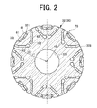
- FIG. 2 is a cross-sectional view of the rotor 30 (cross-sectional view taken along a plane perpendicular to the axial direction).
- a reference reference numeral may be attached only to a part of a plurality of parts having the same attribute.
- FIG. 1 shows the rotating shaft 12 of the motor 1.
- the axial direction refers to the direction in which the rotation axis (rotation center) 12 of the motor 1 extends
- the radial direction refers to the radial direction centered on the rotation shaft 12. Therefore, the radial outer side refers to the side away from the rotating shaft 12, and the radial inner side refers to the side toward the rotating shaft 12. Further, the circumferential direction corresponds to the rotation direction around the rotation axis 12.
- the motor 1 may be a vehicle driving motor used in, for example, a hybrid vehicle or an electric vehicle. However, the motor 1 may be used for any other purpose.
- the motor 1 is an inner rotor type, and the stator 21 is provided so as to surround the radial outside of the rotor 30.
- the outer side of the stator 21 is fixed to the motor housing 10.
- the stator 21 includes, for example, a stator core 211 made of an annular magnetic laminated steel plate, and a plurality of slots (not shown) around which the coil 22 is wound are formed inside the stator core 211 in the radial direction.
- the rotor 30 is arranged inside the stator 21 in the radial direction.
- the rotor 30 includes a rotor core 32, a rotor shaft 34, end plates 35A and 35B, and permanent magnets 61 and 62.
- the rotor core 32 is fixed to the radial outer surface of the rotor shaft 34 and rotates integrally with the rotor shaft 34.
- the rotor core 32 has a shaft hole 320 (see FIG. 2), and the rotor shaft 34 is fitted into the shaft hole 320.
- the rotor core 32 may be fixed to the rotor shaft 34 by shrink fitting, press fitting, or the like.
- the rotor core 32 may be coupled to the rotor shaft 34 by key coupling or spline coupling.
- the rotor shaft 34 is rotatably supported by the motor housing 10 via bearings 14a and 14b.
- the rotor shaft 34 defines the rotating shaft 12 of the motor 1.
- the rotor core 32 is formed of, for example, an annular magnetic laminated steel plate. Permanent magnets 61 and 62 (see FIG. 2) are embedded in the rotor core 32. That is, the rotor core 32 has magnet holes 321 and 322 (see FIG. 2) penetrating in the axial direction, and the permanent magnets 61 and 62 are inserted and fixed in the magnet holes 321 and 322.
- the rotor core 32 may be formed of a green compact obtained by compressing and solidifying the magnetic powder.
- the rotor core 32 is designed in a circular shape having a first radius r1, and the outer peripheral surface of the rotor core 32 includes a portion having a first radius r1 (outer peripheral surface portion 328B, portion 328C, etc., which will be described later).
- the outer peripheral surface of the rotor core 32 has a first radius r1 except for the recess 70 described later.
- the circular shape of the rotor core 32 does not have to be a perfect circle, and may be, for example, a circular shape having a notch in a part thereof.
- the rotor core 32 has a rotationally symmetric form centered on the rotation axis 12 when viewed in the axial direction.
- the rotor core 32 has a form in which the permanent magnets 61 and 62 of each set overlap each time the rotor core 32 rotates 45 degrees with respect to the rotation shaft 12.
- the plurality of permanent magnets 61 and 62 may be formed of neodymium or the like.
- the plurality of permanent magnets 61 and 62 are substantially V-shaped (diameter) in which two types of permanent magnets 61 and 62 are paired with each other when viewed in the axial direction. It is arranged in a substantially V-shape in which the outside in the direction opens.
- a common magnetic pole is formed between the pair of permanent magnets 61 and between the pair of permanent magnets 62.
- the plurality of permanent magnets 61 and 62 are arranged in such a manner that S poles and N poles appear alternately in the circumferential direction. In this embodiment, the number of magnetic poles is eight, but the number of magnetic poles is arbitrary.
- FIG. 1 shows a motor 1 having a specific structure
- the structure of the motor 1 is not limited to such a specific structure.
- the rotor shaft 34 is hollow, but may be solid.
- the end plates 35A and 35B have substantially the same outer diameter as the outer diameter of the rotor core 32 and have substantially the same inner diameter as the inner diameter of the rotor core 32, but are not limited thereto.
- the end plates 35A and 35B may have an outer diameter significantly smaller than the outer diameter of the rotor core 32.
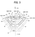
- FIG. 3 is an enlarged view of a portion related to one magnetic pole shown in FIG.
- the configuration relating to one magnetic pole is basically symmetrical with respect to the d-axis (in English, "d-axis" in FIG. 3).
- the outer side in the circumferential direction refers to the side away from the d-axis.
- the rotor core 32 has a magnet hole 321 on the outer side in the radial direction (hereinafter referred to as “first magnet hole 321”) and a magnet hole 322 on the inner side in the radial direction (hereinafter referred to as “second magnet hole 322”). It is formed.
- the first magnet hole 321 is formed in a substantially V shape (a substantially V shape in which the outer side in the radial direction opens) in pairs.
- two first magnet holes 321 may be formed in a straight line as a pair, or only one may be formed in a straight line (a straight line perpendicular to the d-axis). ..
- a permanent magnet 61 is provided in each of the first magnet holes 321.
- a gap may be provided between the first magnet hole 321 and the permanent magnet 61 at both ends of the permanent magnet 61 in the longitudinal direction.
- the gap may be hollow or may be filled with resin or the like.
- the second magnet hole 322 is provided radially inside the first magnet hole 321.
- the second magnet hole 322 is formed in a substantially V-shape (a substantially V-shape in which the outer side in the radial direction opens) in pairs.
- the pair of second magnet holes 322 has a wider extending range in the circumferential direction than the pair of first magnet holes 321.
- a permanent magnet 62 is provided in each of the second magnet holes 322.
- a gap may be provided between the second magnet hole 322 and the permanent magnet 62 at both ends of the permanent magnet 62 in the longitudinal direction.
- the gap may be hollow or may be filled with resin or the like.
- the rotor core 32 has three portions 3211, 3212, and 3213 (hereinafter, first portion 3211) that are connected only via a bridge portion in the radial direction. , Second site 3212, also referred to as third site 3213).
- the first portion 3211 extends radially outward from the first magnet hole 321.
- the first portion 3211 forms a part 328A of the outer peripheral surface 328 of the rotor core 32.
- the second portion 3212 passes between the second magnet hole 322 and the first magnet hole 321 and extends on both sides in the circumferential direction to the outer peripheral surface 328 of the rotor core 32.
- the second portion 3212 forms a part 328B of the outer peripheral surface 328 of the rotor core 32 (hereinafter, also referred to as “the outer peripheral surface portion 328B of the second portion 3212”) on both sides in the circumferential direction of the first portion 3211.
- the second portion 3212 forms a magnetic path of the q-axis magnetic flux.
- the q-axis magnetic flux is applied to the second magnet hole 322 and the first magnet hole 321 from one end (one side outer peripheral surface portion 328B) to the other end (the other side outer peripheral surface portion 328B) of the second portion 3212. It flows through between.
- the third portion 3213 passes radially inside the second magnet hole 322 and extends on both sides in the circumferential direction to the outer peripheral surface 328 of the rotor core 32.
- the third portion 3213 forms a part 328C of the outer peripheral surface 328 of the rotor core 32 on both sides in the circumferential direction of the second portion 3212.
- the mass of the third site 3213 is significantly larger than the mass of the second site 3212, and the mass of the second site 3212 is significantly larger than the mass of the first site 3211.
- the rotor core 32 has a plurality of bridge portions 41, 42, 43, 44 connecting the three portions 3211, 3212, 3213 by having such three portions 3211, 3212, 3213.
- the bridge portion 41 (hereinafter referred to as “first bridge portion 41”) supports the first portion 3211 radially outward with respect to the second portion 3212. That is, the first bridge portion 41 connects the second portion 3212 and the first portion 3211 and extends in the circumferential direction.
- the first bridge portions 41 are provided in pairs on both sides in the circumferential direction (outside in the circumferential direction) of the first portion 3211.
- the first bridge portion 41 extends between the outer peripheral surface 328 of the rotor core 32 and the first magnet hole 321.
- the first bridge portion 41 extends radially inward from the outermost diameter position (position of the first radius r1) of the rotor core 32.
- the rotor core 32 has a concave portion 70 recessed inward in the radial direction on the outer peripheral surface 328, and the first bridge portion 41 is located between the concave portion 70 and the first magnet hole 321.
- the outer peripheral surface 328 of the rotor core 32 has a recess 70 having a second radius r2 smaller than the first radius r1, and the first bridge portion 41 has the outer peripheral surface of the second radius r2 and the first magnet hole 321. Form a part of the peripheral wall surface of.
- the second radius r2 related to the recess 70 does not have to be constant, and as can be seen from FIG. 3, the second radius r2 is continuous from the first radius r1 along the circumferential direction in such a manner that it is minimized near the center in the circumferential direction. May change to.
- the first bridge portion 41 extends in the circumferential direction in a form in which the width is wider at both ends than the central portion. That is, the width of the first bridge portion 41 becomes wider at the connection position P1 with the first portion 3211 and the connection position P2 with the second portion 3212. This makes it possible to reduce or eliminate the stress concentration that may occur at both ends of the first bridge portion 41.
- connection position P1 or P2 connection position P2
- connection position P2 connection position P2
- the first bridge portion 41 may extend in the circumferential direction in a manner in which the center position in the width direction is located concentrically along the circumferential direction, but as shown in FIG. 3, the aspect is the same. It may extend in the circumferential direction in a different manner. In the example shown in FIG. 3, the first bridge portion 41 extends in the circumferential direction in such a manner that the center position in the width direction gradually moves inward in the radial direction toward the outside in the circumferential direction.
- the bridge portion 42 (hereinafter referred to as “second bridge portion 42”) supports the second portion 3212 radially outward with respect to the third portion 3213. That is, the second bridge portion 42 connects the third portion 3213 and the second portion 3212 and extends in the circumferential direction.
- the second bridge portions 42 are provided in pairs on both sides in the circumferential direction (outside in the circumferential direction) of the second portion 3212.
- the second bridge portion 42 extends between the outer peripheral surface 328 of the rotor core 32 and the second magnet hole 322.
- the second bridge portion 42 extends radially outside the first bridge portion 41 in the circumferential direction. That is, the first bridge portion 41 is arranged radially inside the second bridge portion 42.
- the radial positional relationship of each bridge such as the first bridge portion 41 and the second bridge portion 42 is determined based on the radial positional relationship between the center positions such as the centroid position and the center of gravity position. May be done.
- the radial positional relationship between the first bridge portion 41 and the second bridge portion 42 is the relationship between the radius of the center position between the connection positions P1 and P2 and the radius of the center position between the connection positions P3 and P4 described later. It may be judged based on.
- the second bridge portion 42 forms a part of the outer peripheral surface 328 of the rotor core 32.
- the outer peripheral surface portion formed by the second bridge portion 42 on the outer peripheral surface 328 of the rotor core 32 is a portion without a recess such as the recess 70. That is, the second bridge portion 42 forms the outermost diameter position (position of the first radius r1) of the rotor core 32.
- the second bridge portion 42 may also be formed between the recess such as the recess 70 and the second magnet hole 322.
- the recess is formed so that the recess in the radial direction is shallower than that of the recess 70. That is, the second bridge portion 42 is formed so that its outermost diameter position is radially outside the outermost diameter position of the first bridge portion 41.
- the width of the second bridge portion 42 is substantially constant, and the center position in the width direction is located concentrically along the circumferential direction, and extends in the circumferential direction. Not limited to this. Further, in the example shown in FIG. 3, the second bridge portion 42 extends in the circumferential direction in a form in which the width is wider at both ends than the central portion. That is, the width of the second bridge portion 42 becomes wider at the connection position P3 with the second portion 3212 and the connection position P4 with the third portion 3213. This makes it possible to reduce or eliminate the stress concentration that may occur at both ends of the second bridge portion 42.
- the second bridge portion 42 is the radial inner side surface (second magnet hole 322).
- the width is widened in such a manner that only the wall surface) moves inward in the radial direction.
- the bridge portion 43 (hereinafter referred to as “first center bridge portion 43”) supports the first portion 3211 on the d-axis with respect to the second portion 3212.
- the bridge portion 44 (hereinafter referred to as "second center bridge portion 44") supports the second portion 3212 on the d-axis with respect to the third portion 3213.
- the width of the second center bridge portion 44 may be larger than the width of the first center bridge portion 43.
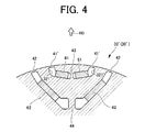
- FIG. 4 is an explanatory view of the rotor 30'by a comparative example, and is a cross-sectional view in comparison with FIG.
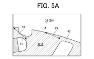
- FIG. 5A is an explanatory diagram of the force generated in the rotor 30 according to the present embodiment, and is an explanatory diagram of the stress reduction principle.
- FIG. 5B is an explanatory diagram of the force generated in the rotor 30'by the comparative example as a comparison.
- the rotor 30'according to the comparative example is different from the rotor 30 according to the present embodiment in that the rotor core 32 is replaced with the rotor core 32'.
- the first magnet hole 321 is replaced with the first magnet hole 321'and the first bridge portion 41 is replaced with the first bridge portion 41'with respect to the rotor core 32 according to the present embodiment.
- the points that were made are different.
- the first bridge portion 41' extends to the outermost diameter position of the rotor core 32 as shown in FIG. 4, unlike the first bridge portion 41 according to the present embodiment.
- a centrifugal force (see arrow R0), which is an outward force along the radial direction, acts on the rotor 30.
- the first bridge portion 41 and the first center bridge portion 43 resist the centrifugal force corresponding to the mass of the first portion 3211 and the permanent magnet 61 to the second portion 3212.
- the first site 3211 is supported.
- the second bridge portion 42 and the second center bridge portion 44 have a third portion against the centrifugal force corresponding to the mass of the first portion 3211, the permanent magnet 61, the second portion 3212, and the permanent magnet 62.
- the second site 3212 is supported with respect to the site 3213. Since the centrifugal force increases as the mass increases, the centrifugal force acting on the second bridge portion 42 and the second center bridge portion 44 is larger than the centrifugal force acting on the first bridge portion 41 and the first center bridge portion 43. Will also grow. Therefore, relatively high stress is likely to occur at both end positions (connection positions P3 and P4) of the second bridge portion 42 and in the vicinity thereof.
- the second bridge portion 42 is located when centrifugal force is generated.
- the stress for example, the stress that can occur at or near both ends of the second bridge portion 42
- the stress can be reduced.
- the first bridge portion 41' is formed.
- a force F1 that is pulled in the d-axis direction is generated. Since such a force F1 acts at the same outermost diameter position as the second bridge portion 42, it also acts on the second bridge portion 42 as a force F2 pulled in the d-axis direction.
- the second bridge portion 42 is deformed in a curved manner due to the force F1, and stress concentration is likely to occur.
- the first bridge portion 41 At the end of the second portion 3212 in the above, a force F3 that is pulled in the d-axis direction is generated.
- the end portion on the second portion 3212 side is located radially inside the outermost diameter position, so that the force F3 is reduced. It is a component of the force that pulls inward in the radial direction from the second bridge portion 42.
- the direction of the force F4 acting on the second bridge portion 42 due to the direction of the force F3 changes from the direction of the same force F2 in the case of the comparative example.
- the component along the radial direction of the force F4 (the component outward in the radial direction) is reduced.
- the stress of the second bridge portion 42 (for example, the stress that can occur at or near both ends of the second bridge portion 42) can be reduced when centrifugal force is generated.
- the second bridge portion reaches when centrifugal force is generated.
- the curvature of 42 can be relaxed.
- the stress of the second bridge portion 42 can be reduced when centrifugal force is generated.
- the end portion of the first bridge portion 41 on the second portion 3212 side (see the connection position P2 in FIG. 3) is located radially inside the outermost diameter position of the rotor core 32. However, it contributes to the stress reduction of the second bridge portion 42. More essentially, the end of the first bridge 41 on the second portion 3212 side (see connection position P2 in FIG. 3) is the end of the second bridge 42 on the second portion 3212 side (connection in FIG. 3). The position on the inner side in the radial direction from the position P3) contributes to the stress reduction of the second bridge portion 42. Therefore, when such a positional relationship is realized, the same effect can be obtained even if the structure is slightly different from the specific structure shown in FIG. For example, although not shown, the end portion of the first bridge portion 41 on the first portion 3211 side (see the connection position P1 in FIG. 3) may be located radially outside of FIG. 3, for example, the outermost diameter. It may be located in a position.
- FIG. 6 is an enlarged cross-sectional view of a part of the rotor 30A according to the first modification.
- FIG. 6 shows a configuration relating to one magnetic pole as in FIG. 3 described above, but the same may apply to a configuration relating to another magnetic pole.
- the configuration related to one magnetic pole is symmetrical with respect to the d-axis, as in the rotor 30 according to the above-described embodiment.
- the rotor 30A according to the first modification is different from the rotor 30 according to the above-described embodiment in that the rotor core 32 is replaced with the rotor core 32A and the two permanent magnets 61 are replaced with the single permanent magnet 61A. ..
- the rotor core 32A is different from the above-mentioned rotor 30 in that the two first magnet holes 321 are replaced by a single first magnet hole 321A and the hole 323 penetrating in the axial direction is provided. Further, the rotor core 32A does not include the first center bridge portion 43 because the two first magnet holes 321 are replaced by the single first magnet hole 321A.
- the first magnet hole 321A extends linearly in the circumferential tangential direction (direction perpendicular to the d-axis). Also in this case, the first magnet hole 321A cooperates with the recess 70 to form the first portion 3211.
- a permanent magnet 61A is provided in the first magnet hole 321A.
- the permanent magnet 61A also extends in the tangential direction in the circumferential direction. In this case, the permanent magnet 61A does not form a V shape.
- the hole 323 is provided between the pair of second magnet holes 322.
- the second portion 3212 extends between the hole 323 and the first magnet hole 321A and between the second magnet hole 322 and the first magnet hole 321A to the outer peripheral surface 328 of the rotor core 32 on both sides in the circumferential direction.
- two second center bridge portions 44A are formed on both sides of the hole 323 in the circumferential direction (see the portions 441 and 442 in FIG. 6).
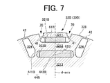
- FIG. 7 is an enlarged cross-sectional view of a part of the rotor 30B according to the second modification.
- FIG. 7 shows a configuration relating to one magnetic pole as in FIG. 3 described above, but the same may apply to a configuration relating to another magnetic pole.
- the configuration related to one magnetic pole is symmetrical with respect to the d-axis, as in the rotor 30 according to the above-described embodiment.
- the rotor core 32B has a point where two first magnet holes 321 are replaced with a single first magnet hole 321B and two second magnet holes 322 are a single second magnet hole with respect to the rotor 30 described above.
- the point replaced by 322B and the point where the hole 324 is provided are different.
- the rotor core 32B does not include the first center bridge portion 43 because the two first magnet holes 321 are replaced by the single first magnet hole 321B.
- the first magnet hole 321B extends in the tangential direction in the circumferential direction, like the first magnet hole 321A according to the first modification described above. Also in this case, the first magnet hole 321B cooperates with the recess 70 to form the first portion 3211.
- a permanent magnet 61B is provided in the first magnet hole 321B.
- the permanent magnet 61B also extends in the tangential direction in the circumferential direction. In this case, the permanent magnet 61B does not form a V shape.
- the second magnet hole 322B extends in the tangential direction in the circumferential direction.
- the second magnet hole 322B is arranged radially inside the first magnet hole 321B, which is the same as the above-described embodiment and the first modification.
- a permanent magnet 62B is provided in the second magnet hole 322B.
- the permanent magnet 62B does not form a V shape.
- the holes 324 are provided on both sides of the second magnet hole 322B in the circumferential direction in a paired manner.
- the second portion 3212 passes between each hole 324 and the first magnet hole 321B, and between the second magnet hole 322B and the first magnet hole 321B, and both sides in the circumferential direction reach the outer peripheral surface 328 of the rotor core 32. It is postponed. Since the holes 324 are provided on both sides of the second magnet hole 322B in the circumferential direction, the second center bridge portion 44B is formed on both sides of the second magnet hole 322B in the circumferential direction (see the portions 441B and 442B in FIG. 7). ).
Landscapes
- Engineering & Computer Science (AREA)
- Power Engineering (AREA)
- Permanent Field Magnets Of Synchronous Machinery (AREA)
- Iron Core Of Rotating Electric Machines (AREA)
Abstract
Description
そこで、本開示は、ロータコアに径方向内側の磁石孔と径方向外側の磁石孔とが形成された回転電機用ロータにおいて、ブリッジ部の応力を低減することを目的とする。
磁極のそれぞれに対して径方向外側の第1磁石孔と径方向内側の第2磁石孔とが形成されたロータコアと、
前記第1磁石孔及び前記第2磁石孔に設けられ、前記複数の磁極を形成する複数の永久磁石とを備え、
前記ロータコアは、前記第1磁石孔よりも径方向外側の第1部位と、前記第1磁石孔と前記第2磁石孔との間を通って周方向両側が前記ロータコアの外周面まで延在する第2部位と、前記第2磁石孔よりも径方向内側を通って周方向両側が前記ロータコアの外周面まで延在する第3部位と、前記第2部位と前記第1部位とを連結しかつ前記ロータコアの外周面の一部を形成する第1ブリッジ部と、前記第3部位と前記第2部位とを連結しかつ前記ロータコアの外周面の一部を形成する第2ブリッジ部とを含み、
前記第1ブリッジ部は、前記第2ブリッジ部よりも径方向内側に配置される、回転電機用ロータが提供される。
ロータコア32は、第1半径r1の円形状で設計され、ロータコア32の外周面は、第1半径r1を有する部分(後述する外周面部328B、部分328C等)を含む。本実施例では、ロータコア32の外周面は、後述する凹部70を除き、第1半径r1を有する。なお、変形例では、ロータコア32の円形状は、真円である必要はなく、例えば一部に切り欠きを有する円形状であってもよい。
Claims (5)
- 周方向に沿って複数の磁極を有する回転電機用ロータであって、
磁極のそれぞれに対して径方向外側の第1磁石孔と径方向内側の第2磁石孔とが形成されたロータコアと、
前記第1磁石孔及び前記第2磁石孔に設けられ、前記複数の磁極を形成する複数の永久磁石とを備え、
前記ロータコアは、前記第1磁石孔よりも径方向外側の第1部位と、前記第1磁石孔と前記第2磁石孔との間を通って周方向両側が前記ロータコアの外周面まで延在する第2部位と、前記第2磁石孔よりも径方向内側を通って周方向両側が前記ロータコアの外周面まで延在する第3部位と、前記第2部位と前記第1部位とを連結しかつ前記ロータコアの外周面の一部を形成する第1ブリッジ部と、前記第3部位と前記第2部位とを連結しかつ前記ロータコアの外周面の一部を形成する第2ブリッジ部とを含み、
前記第1ブリッジ部は、前記第2ブリッジ部よりも径方向内側に配置される、回転電機用ロータ。 - 前記ロータコアは、第1半径の円形状で設計され、前記ロータコアの外周面は、前記第1半径を有する部分を含み、
前記第2ブリッジ部は、前記ロータコアにおける前記第1半径の外周面の一部を形成する、請求項1に記載の回転電機用ロータ。 - 前記ロータコアの外周面は、前記第1半径よりも小さい第2半径を有する凹部を更に含み、
前記第1ブリッジ部は、前記凹部と前記第1磁石孔との間に位置する、請求項2に記載の回転電機用ロータ。 - 前記第1ブリッジ部は、前記複数の磁極のそれぞれごとに、前記第1部位の周方向両側に対で設けられ、
前記第2ブリッジ部は、前記複数の磁極のそれぞれごとに、前記第2部位の周方向両側に対で設けられる、請求項1から3のうちのいずれか1項に記載の回転電機用ロータ。 - 前記第2磁石孔は、前記複数の磁極のそれぞれごとに、回転電機の回転軸を通り径方向に平行な直線に関して対称に、径方向外側が開くV字状に対で配置され、
前記第1磁石孔は、前記複数の磁極のそれぞれごとに、前記直線に関して対称に、径方向外側が開くV字状に対で配置される、請求項1から4のうちのいずれか1項に記載の回転電機用ロータ。
Priority Applications (4)
| Application Number | Priority Date | Filing Date | Title |
|---|---|---|---|
| JP2022530016A JP7468640B2 (ja) | 2020-06-08 | 2021-01-14 | 回転電機用ロータ |
| EP21822462.4A EP4102686A4 (en) | 2020-06-08 | 2021-01-14 | ROTOR FOR DYNAMOELECTRIC MACHINE |
| CN202180037703.XA CN115668694B (zh) | 2020-06-08 | 2021-01-14 | 旋转电机用转子 |
| US17/926,941 US12283848B2 (en) | 2020-06-08 | 2021-01-14 | Rotor for rotary electric machine |
Applications Claiming Priority (2)
| Application Number | Priority Date | Filing Date | Title |
|---|---|---|---|
| JP2020-099190 | 2020-06-08 | ||
| JP2020099190 | 2020-06-08 |
Publications (1)
| Publication Number | Publication Date |
|---|---|
| WO2021250921A1 true WO2021250921A1 (ja) | 2021-12-16 |
Family
ID=78847156
Family Applications (1)
| Application Number | Title | Priority Date | Filing Date |
|---|---|---|---|
| PCT/JP2021/000990 Ceased WO2021250921A1 (ja) | 2020-06-08 | 2021-01-14 | 回転電機用ロータ |
Country Status (5)
| Country | Link |
|---|---|
| US (1) | US12283848B2 (ja) |
| EP (1) | EP4102686A4 (ja) |
| JP (1) | JP7468640B2 (ja) |
| CN (1) | CN115668694B (ja) |
| WO (1) | WO2021250921A1 (ja) |
Cited By (3)
| Publication number | Priority date | Publication date | Assignee | Title |
|---|---|---|---|---|
| CN116830425A (zh) * | 2022-01-05 | 2023-09-29 | 株式会社东芝 | 转子 |
| JP2023154479A (ja) * | 2022-04-07 | 2023-10-20 | 株式会社豊田中央研究所 | 回転電機 |
| EP4576502A4 (en) * | 2022-10-27 | 2025-12-17 | Aisin Corp | ROTOR |
Families Citing this family (2)
| Publication number | Priority date | Publication date | Assignee | Title |
|---|---|---|---|---|
| US20230318375A1 (en) * | 2020-08-31 | 2023-10-05 | Nidec Corporation | Rotary electric machine |
| JP7404557B2 (ja) * | 2021-11-05 | 2023-12-25 | 株式会社東芝 | 回転電機の回転子 |
Citations (4)
| Publication number | Priority date | Publication date | Assignee | Title |
|---|---|---|---|---|
| JP2012075208A (ja) * | 2010-09-28 | 2012-04-12 | Honda Motor Co Ltd | ロータ |
| JP2012161227A (ja) * | 2011-02-03 | 2012-08-23 | Toyota Motor Corp | 回転電機用回転子 |
| JP2012161226A (ja) | 2011-02-03 | 2012-08-23 | Toyota Motor Corp | 回転電機用回転子 |
| JP2016032424A (ja) * | 2014-07-30 | 2016-03-07 | トヨタ自動車株式会社 | ロータコアの製造方法 |
Family Cites Families (5)
| Publication number | Priority date | Publication date | Assignee | Title |
|---|---|---|---|---|
| JP2000316241A (ja) * | 1999-04-27 | 2000-11-14 | Toyota Motor Corp | 永久磁石埋め込み式モータ |
| JP4248778B2 (ja) | 2001-10-25 | 2009-04-02 | アイチエレック株式会社 | 永久磁石形電動機の回転子 |
| GB201619856D0 (en) | 2016-11-24 | 2017-01-11 | Jaguar Land Rover Ltd | Electric machine apparatus |
| GB201620300D0 (en) * | 2016-11-30 | 2017-01-11 | Jaguar Land Rover Ltd | Electric machine apparatus |
| JP6740940B2 (ja) * | 2017-03-16 | 2020-08-19 | トヨタ自動車株式会社 | 回転電機のロータ |
-
2021
- 2021-01-14 US US17/926,941 patent/US12283848B2/en active Active
- 2021-01-14 JP JP2022530016A patent/JP7468640B2/ja active Active
- 2021-01-14 EP EP21822462.4A patent/EP4102686A4/en active Pending
- 2021-01-14 WO PCT/JP2021/000990 patent/WO2021250921A1/ja not_active Ceased
- 2021-01-14 CN CN202180037703.XA patent/CN115668694B/zh active Active
Patent Citations (4)
| Publication number | Priority date | Publication date | Assignee | Title |
|---|---|---|---|---|
| JP2012075208A (ja) * | 2010-09-28 | 2012-04-12 | Honda Motor Co Ltd | ロータ |
| JP2012161227A (ja) * | 2011-02-03 | 2012-08-23 | Toyota Motor Corp | 回転電機用回転子 |
| JP2012161226A (ja) | 2011-02-03 | 2012-08-23 | Toyota Motor Corp | 回転電機用回転子 |
| JP2016032424A (ja) * | 2014-07-30 | 2016-03-07 | トヨタ自動車株式会社 | ロータコアの製造方法 |
Non-Patent Citations (1)
| Title |
|---|
| See also references of EP4102686A4 |
Cited By (6)
| Publication number | Priority date | Publication date | Assignee | Title |
|---|---|---|---|---|
| CN116830425A (zh) * | 2022-01-05 | 2023-09-29 | 株式会社东芝 | 转子 |
| EP4462650A4 (en) * | 2022-01-05 | 2025-08-27 | Toshiba Kk | ROTOR |
| US12537404B2 (en) | 2022-01-05 | 2026-01-27 | Kabushiki Kaisha Toshiba | Rotor |
| JP2023154479A (ja) * | 2022-04-07 | 2023-10-20 | 株式会社豊田中央研究所 | 回転電機 |
| JP7784341B2 (ja) | 2022-04-07 | 2025-12-11 | 株式会社豊田中央研究所 | 回転電機 |
| EP4576502A4 (en) * | 2022-10-27 | 2025-12-17 | Aisin Corp | ROTOR |
Also Published As
| Publication number | Publication date |
|---|---|
| JP7468640B2 (ja) | 2024-04-16 |
| EP4102686A4 (en) | 2023-08-09 |
| CN115668694A (zh) | 2023-01-31 |
| EP4102686A1 (en) | 2022-12-14 |
| US20230198324A1 (en) | 2023-06-22 |
| JPWO2021250921A1 (ja) | 2021-12-16 |
| US12283848B2 (en) | 2025-04-22 |
| CN115668694B (zh) | 2026-03-24 |
Similar Documents
| Publication | Publication Date | Title |
|---|---|---|
| WO2021250921A1 (ja) | 回転電機用ロータ | |
| US20190348879A1 (en) | Rotor for rotating electric machine | |
| US11264878B2 (en) | Rotor for rotary electric machine and method of manufacturing rotary electric machine | |
| KR20120110025A (ko) | 회전 전기 기계용 영구 자석 매설형 회전자 및 회전 전기 기계 | |
| US11190070B2 (en) | Rotor for rotating electrical machine | |
| US8519593B2 (en) | Brushless motor with low cogging torque | |
| US20230412018A1 (en) | Rotor core | |
| EP3142224A1 (en) | Single phase permanent magnet motor | |
| JPWO2020194709A1 (ja) | 回転電機 | |
| US12519356B2 (en) | Rotor and rotating electric machine | |
| KR100624381B1 (ko) | 영구자석 매립형 전동기의 회전자와 그 제조방법 | |
| EP3866305A1 (en) | Rotor, and rotary electric machine provided with same | |
| JP2015220846A (ja) | 回転電機の回転子 | |
| WO2023276680A1 (ja) | 回転電機 | |
| JP7619233B2 (ja) | 回転電機用ロータ | |
| CN109980814A (zh) | 内置式永磁电机转子和永磁电机 | |
| EP4668544A1 (en) | Rotating electric machine rotor | |
| CN116458033A (zh) | 旋转电机的转子 | |
| EP4664726A1 (en) | Rotor for rotating electric machine | |
| JP7852733B2 (ja) | 回転電機用ロータ | |
| US20250070605A1 (en) | Rotor for rotating electrical machine | |
| EP4718685A1 (en) | Rotor for rotary electric machine | |
| JP2014096869A (ja) | 磁石埋込型モータの回転子 | |
| US11962190B2 (en) | Rotor of rotary electric machine | |
| JP2024059134A (ja) | 回転電機用ロータ |
Legal Events
| Date | Code | Title | Description |
|---|---|---|---|
| 121 | Ep: the epo has been informed by wipo that ep was designated in this application |
Ref document number: 21822462 Country of ref document: EP Kind code of ref document: A1 |
|
| ENP | Entry into the national phase |
Ref document number: 2022530016 Country of ref document: JP Kind code of ref document: A |
|
| ENP | Entry into the national phase |
Ref document number: 2021822462 Country of ref document: EP Effective date: 20220905 |
|
| NENP | Non-entry into the national phase |
Ref country code: DE |
|
| WWG | Wipo information: grant in national office |
Ref document number: 17926941 Country of ref document: US |