WO2021255877A1 - 長尺状医療用装置 - Google Patents
長尺状医療用装置 Download PDFInfo
- Publication number
- WO2021255877A1 WO2021255877A1 PCT/JP2020/023859 JP2020023859W WO2021255877A1 WO 2021255877 A1 WO2021255877 A1 WO 2021255877A1 JP 2020023859 W JP2020023859 W JP 2020023859W WO 2021255877 A1 WO2021255877 A1 WO 2021255877A1
- Authority
- WO
- WIPO (PCT)
- Prior art keywords
- pulley
- tip
- end side
- bent
- medical device
- Prior art date
- Legal status (The legal status is an assumption and is not a legal conclusion. Google has not performed a legal analysis and makes no representation as to the accuracy of the status listed.)
- Ceased
Links
Images






Classifications
-
- A—HUMAN NECESSITIES
- A61—MEDICAL OR VETERINARY SCIENCE; HYGIENE
- A61M—DEVICES FOR INTRODUCING MEDIA INTO, OR ONTO, THE BODY; DEVICES FOR TRANSDUCING BODY MEDIA OR FOR TAKING MEDIA FROM THE BODY; DEVICES FOR PRODUCING OR ENDING SLEEP OR STUPOR
- A61M25/00—Catheters; Hollow probes
- A61M25/01—Introducing, guiding, advancing, emplacing or holding catheters
- A61M25/0105—Steering means as part of the catheter or advancing means; Markers for positioning
- A61M25/0133—Tip steering devices
- A61M25/0147—Tip steering devices with movable mechanical means, e.g. pull wires
-
- A—HUMAN NECESSITIES
- A61—MEDICAL OR VETERINARY SCIENCE; HYGIENE
- A61M—DEVICES FOR INTRODUCING MEDIA INTO, OR ONTO, THE BODY; DEVICES FOR TRANSDUCING BODY MEDIA OR FOR TAKING MEDIA FROM THE BODY; DEVICES FOR PRODUCING OR ENDING SLEEP OR STUPOR
- A61M25/00—Catheters; Hollow probes
- A61M25/01—Introducing, guiding, advancing, emplacing or holding catheters
- A61M25/0105—Steering means as part of the catheter or advancing means; Markers for positioning
- A61M25/0133—Tip steering devices
- A61M25/0136—Handles therefor
-
- A—HUMAN NECESSITIES
- A61—MEDICAL OR VETERINARY SCIENCE; HYGIENE
- A61M—DEVICES FOR INTRODUCING MEDIA INTO, OR ONTO, THE BODY; DEVICES FOR TRANSDUCING BODY MEDIA OR FOR TAKING MEDIA FROM THE BODY; DEVICES FOR PRODUCING OR ENDING SLEEP OR STUPOR
- A61M25/00—Catheters; Hollow probes
- A61M25/01—Introducing, guiding, advancing, emplacing or holding catheters
- A61M25/09—Guide wires
- A61M2025/09116—Design of handles or shafts or gripping surfaces thereof for manipulating guide wires
-
- A—HUMAN NECESSITIES
- A61—MEDICAL OR VETERINARY SCIENCE; HYGIENE
- A61M—DEVICES FOR INTRODUCING MEDIA INTO, OR ONTO, THE BODY; DEVICES FOR TRANSDUCING BODY MEDIA OR FOR TAKING MEDIA FROM THE BODY; DEVICES FOR PRODUCING OR ENDING SLEEP OR STUPOR
- A61M25/00—Catheters; Hollow probes
- A61M25/01—Introducing, guiding, advancing, emplacing or holding catheters
- A61M25/09—Guide wires
- A61M2025/0915—Guide wires having features for changing the stiffness
Definitions
- the present invention relates to a long medical device such as a catheter device and an endoscope.
- the catheter device inserted into the heart from a blood vessel needs to appropriately guide the tip of the flexible catheter body to the target site in the heart.
- it is necessary to appropriately guide the imaging site at the tip from the nasal cavity or oral cavity to the target site and in particular, there is a long medical device provided with a site that bends in a desired direction on the tip side. is doing.
- Patent Document 1 describes a technique for bending the tip of a catheter body in two opposite directions by rotating an operation wire holding handle integrally connected to a wire stop disk to which a pair of wires are connected with a fingertip. Is disclosed.
- the present invention has been made in view of the above problems, and an object of the present invention is to provide a technique capable of easily bending the tip of the main body of a long medical device.
- the long medical device is arranged on the tip side, and the bendable portion and the tip portion of the bend portion are spaced apart from each other in a predetermined first direction. It is provided with two connected operation lines and an operation unit that can be operated by a user and whose base end side of the two operation lines is connected at intervals in the first direction. By bending the operating portion in the first direction, the bent portion can be bent with respect to the first direction depending on the tension state of the operation lines of the two systems.
- the operation unit is provided with two drive-side pulleys that can be independently driven by power from the user and has a common rotation axis, and the tip portion of the bending portion is the first.
- Two sets of two operating lines connected at intervals in one direction are provided at intervals in the second direction intersecting the first direction, and a pulley portion having a rotating surface intersecting with the drive side pulley is further provided.
- the two drive-side pulleys can move in the first direction around the rotation axis of the pulley portion, and each of the drive-side pulleys is connected to one end side of the tip end side of the bend portion in the first direction.
- the two operating lines lined up in the second direction and the two operating lines lined up in the second direction connected to the other end side of the first direction are respectively via the pulley portion.
- the tip portion of the bending portion is bent. Is bendable in the first direction, and when the two drive-side pulleys are rotated by rotating the operation portion in the second direction, the tip portion of the bent portion can be bent in the second direction. May be good.
- a lumen accommodating an operation line of each system may be formed in the bent portion.
- the bent portion is provided with a lumen for inserting a predetermined device or injecting a drug solution, and a tube communicating with the lumen is radially outward from the bent portion. It may have an opening to derive.
- the bent portion is provided with a lumen for inserting a predetermined device or injecting a drug solution
- the pulley portion is provided on an extension of the central axis of the bent portion.
- a first through hole for inserting a tube communicating with the lumen may be formed in a fixed shaft serving as a rotation center of the above, and a second through hole for inserting the tube may be formed in the operation portion.
- the second through hole may be formed so that the inner diameter on the proximal end side is larger than the inner diameter on the distal end side.
- the tip of the main body of a long medical device can be easily bent.
- FIG. 3 is a cross-sectional view taken along the line AA shown in FIG. 1 of the main body of the catheter device. It is a front view of the tip part of a catheter device. It is a schematic block diagram of a catheter device. It is sectional drawing of the operation part of the catheter device. It is a wiring diagram of a wire rope in a catheter device. It is a figure explaining the vertical bending operation of a catheter device. It is a figure explaining the lateral bending motion of a catheter device. It is a perspective view of the catheter device which concerns on a modification. It is sectional drawing of the catheter device. It is a schematic block diagram of a catheter device. It is sectional drawing of the operation part of the catheter device.
- the "tip side” and the “tip direction” mean the side and the direction in which the portion to be inserted into the body cavity of the long medical device is located.
- the “base end side” and the “base end direction” mean the side and the direction in which the operation unit for applying the power for bending the long medical device is located.
- the “tip” refers to the end portion on the distal end side of any member or portion, and the “base end” indicates the end portion on the proximal end side of any member or portion.
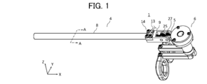
- FIG. 1 is a perspective view of the catheter device according to the embodiment.
- FIG. 2 is a cross-sectional view thereof.
- the illustrated X-axis, Y-axis, and Z-axis are appropriately used. Further, the directions of the X-axis, the Y-axis, and the Z-axis in each figure are basically the same.
- the positive direction of the X-axis indicates the proximal end side, and the opposite indicates the distal end side.
- the Z-axis direction is the vertical direction
- the X-axis is the longitudinal direction
- the Y-axis is the longitudinal direction. It is an orthogonal short direction. Therefore, the Z-axis direction may be referred to as a vertical direction
- the Y-axis direction may be referred to as a left-right direction or a lateral direction.
- the catheter device 1 is an example of a long medical device, for example, a minimally invasive surgical instrument that is guided to a predetermined site in the heart through a blood vessel to perform a predetermined procedure.
- the catheter device 1 includes a main body portion 4, a pulley fixing portion 9, a connecting portion 5, and an operating portion 6.
- the portion (tip portion) on the tip end side of the main body portion 4 can be bent up and down and bent left and right.
- the main body portion 4 is an example of a bent portion, and includes a shaft 8 and a metal ring 10.
- the shaft 8 may be made of, for example, a synthetic resin or the like.
- the metal ring 10 is a metal ring-shaped member, and is connected to the tip of the shaft 8.
- the pulley fixing portion 9 is connected to the base end side of the shaft 8.
- the connecting portion 5 connects the operating portion 6 to the pulley fixing portion 9 so as to be rotatable in the vertical direction.
- the operation unit 6 can rotate in the vertical direction about the rotation axis of the pulley unit 27.
- the operation unit 6 is a portion for a user (for example, a surgeon) to operate the tip side of the main body unit 4 in order to perform a vertical bending operation and a left / right bending operation.
- FIG. 3 is a cross-sectional view of the main body of the catheter device, and shows a cross-sectional view taken along the line AA shown in FIG.
- a lumen (lumen, passage) 12A to 12D for inserting a plurality of (four in this example) wire ropes (an example of an operation line), and the main body 4
- a device used for treatment on the tip side and a treatment lumen 11 for supplying a chemical solution to the tip side are arranged.
- the wire rope 20A is inserted into the lumen 12A
- the wire rope 20B is inserted into the lumen 12B
- the wire rope 20C is inserted into the lumen 12C
- the wire rope 20D is inserted into the lumen 12D.
- the lumens 12A to 12D may be configured by a tube.
- the treatment lumen 11 is formed by a tube 13.
- FIG. 4 is a front view of the tip portion of the catheter device.
- a metal ring 10 is connected to a shaft 8 at the tip of the main body 4. According to the metal ring 10, the tip side of the lumens 12A to 12D is sealed, while the tip side of the treatment lumen 11 is open.
- Wire ropes 20A to 20D are connected to the metal ring 10. As a method of connecting the wire ropes 20A to 20D to the metal ring 10, for example, welding may be performed or bonding may be performed.
- the wire ropes 20A and 20D are at the same height position (lower side) in the Z-axis direction in the metal ring 10 when the treatment lumen 11 is centered in the front view of the tip portion of the main body portion 4.
- the wire ropes 20B and 20C are connected to the same height position (upper side) in the Z-axis direction. That is, the wire ropes 20A and 20D and the wire ropes 20B and 20C are connected at intervals in the Z-axis direction (an example of the first direction).
- the wire ropes 20A and 20B are connected to the same position (left side) in the Y-axis direction in the metal ring 10, and the wire ropes 20C and 20D are connected to the same position (right side) in the Y-axis direction. That is, the wire ropes 20A and 20B and the wire ropes 20C and 20D are connected at intervals in the Y-axis direction (an example of the second direction) intersecting the Z-axis.
- FIG. 5A and 5B are schematic configuration views of the catheter device, FIG. 5A is a top view thereof, FIG. 5B is a side view of the catheter device facing the Y-axis direction, and FIG. 5C is an X-axis view. It is a side view from a direction.
- the pulley portion 25 and the pulley portion 27 are rotatably supported around the rotating shafts 31 and 33, respectively.
- the rotation axis of the pulley portion 25 and the pulley portion 27 is an axis parallel to the Y axis, and the rotation plane is an XX plane (vertical plane).
- an opening 14 for leading out the tube 13 communicating with the treatment lumen 11 of the main body portion 4 upward is formed.
- the pulley portion 25 has four pulleys 26A to 26D.
- the pulleys 26A to 26D are disk-shaped members having a groove portion formed on the outer periphery of the pulley to which a wire rope can be hung, and can rotate independently about the rotation shaft 31.
- the rotary shaft 31 is a non-rotatable fixed shaft, and the pulleys 26A to 26D are rotatable with respect to the rotary shaft 31.
- the pulleys 26A to 26D may be made of, for example, medical stainless steel.
- the pulley portion 27 has four pulleys 28A to 28D.
- the pulleys 28A to 28D are disk-shaped members having a groove formed on the outer periphery on which a wire rope can be hung, and can rotate independently about the rotation shaft 33.
- the rotary shaft 33 is a non-rotatable fixed shaft, and the pulleys 28A to 28D are rotatable with respect to the rotary shaft 33.
- the pulleys 28A to 28D may be made of, for example, medical stainless steel.
- the diameters (pulley diameters) of the pulleys 26A to 26D and 28A to 28D are, for example, 9 mm.
- FIG. 6 is a cross-sectional view of the operation unit of the catheter device.
- the operation unit 6 includes a base end side pulley (drive side pulley) 40, 41, a solid shaft 42 and a hollow shaft 43 as an example of the operation shaft, bearings 44, 45, and keys 46, 47, 50, 51. , With finger hooks 48, 49.
- the base end side pulleys 40 and 41 are disk-shaped members having a groove portion formed on the outer periphery of the pulley so that a wire rope can be hung on the outer periphery thereof, and can rotate independently about the operation shaft.
- the proximal end side pulley 40 is above the proximal end side pulley 41 (plus direction of the Z axis).
- Their rotation axes are common to the axis parallel to the Z axis (vertical axis), and the rotation plane is the XY plane (horizontal plane).
- the rotation axis of the proximal end side pulleys 40 and 41 is perpendicular to the rotation axis 33 of the pulley unit 27, in other words.
- the rotating surface of the base end side pulleys 40 and 41 is perpendicular to the rotating surface of the pulley portion 27.
- the proximal end side pulley 40 and the proximal end side pulley 41 may be made of, for example, medical stainless steel.
- Two lines of wire ropes 20A and 20D are hung on the groove portion of the base end side pulley 40, and one end of each of the two lines of wire rope is fixed.
- Two lines of wire ropes 20B and 20C are hung on the groove portion of the base end side pulley 41, and one end of each of the two lines of wire rope is fixed.
- the wire ropes 20A to 20D are formed by, for example, twisting a plurality of wires (wires).
- the finger hooks 48 and 49 are the parts where one finger of one hand of the user of the catheter device 1 is inserted and the driving force for operating the catheter device 1 is applied.
- the finger hooks 48 and 49 are configured to be located at a position distant from the tip side with respect to the operation axis in the reference state.
- the solid shaft 42 is inserted into the hollow portion of the hollow shaft 43, and is rotatably provided on the inner circumference of the hollow shaft 43 via bearings 44 and 45.
- the base end side pulley 40 is fixed to the solid shaft 42 by the key 46, and can rotate integrally with the solid shaft 42.
- the base end side pulley 41 is fixed to the hollow shaft 43 by the key 47, and can rotate integrally with the hollow shaft 43.
- the finger hook 48 is fixed to the hollow shaft 43 by the key 50 and can rotate integrally with the hollow shaft 43.
- the finger hook 49 is fixed to the solid shaft 42 by the key 51 and can rotate integrally with the solid shaft 42. Therefore, when the user rotates the finger hook 48, the proximal end side pulley 41 rotates in the same direction, and when the user rotates the finger hook 49, the proximal end side pulley 40 rotates in the same direction. ..
- the finger hooks 48 and 49 are located away from the drive shafts (solid shaft 42 and hollow shaft 43), the base end side pulleys 40 and 41 can be rotated by a relatively small force. can.
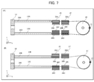
- FIG. 7A shows the wiring of the wire rope between the metal ring 10 and the proximal end side pulley 40
- FIG. 7B shows the arrangement of the wire rope between the metal ring 10 and the proximal end.
- the wiring of the wire rope to and from the side pulley 41 is shown.
- one end of the wire rope 20A is connected to the position on the positive side of the Y axis of the metal ring 10 at the tip of the main body 4.
- the wire rope 20A is hung from the metal ring 10 through the lumen 12A to the proximal end side pulley 40 via the groove on the lower side of the pulley 26A and the groove on the upper side of the pulley 28A.
- the other end of the wire rope 20A is fixed by the fixing member 15.
- One end of the wire rope 20D is connected to the position on the minus side of the Y axis of the metal ring 10 at the tip of the main body 4.
- the wire rope 20D runs from the metal ring 10 through the lumen 12D to the proximal end pulley 40 via the groove on the lower side of the pulley 26D and the groove on the upper side of the pulley 28D.
- the other end of the wire rope 20D is fixed by the fixing member 15.
- one end of the wire rope 20B is connected to the position on the positive side of the Y axis of the metal ring 10 at the tip of the main body 4.
- the wire rope 20B runs from the metal ring 10 through the lumen 12B to the proximal end pulley 41 via the groove on the upper side of the pulley 26B and the groove on the lower side of the pulley 28A.
- the other end of the wire rope 20B is fixed by the fixing member 17.
- One end of the wire rope 20C is connected to the position on the minus side of the Y axis of the metal ring 10 at the tip of the main body 4.
- the wire rope 20C is passed from the metal ring 10 through the lumen 12C to the proximal end side pulley 41 via the groove on the upper side of the pulley 26C and the groove on the upper side of the pulley 28C.
- the other end of the wire rope 20C is fixed by the fixing member 17.
- FIG. 8 is a diagram illustrating a vertical bending operation of the catheter device.
- the side (lower side) can be easily moved in the direction away from the base end side. As a result, the tip of the main body 8 is bent upward. Since each of the wire ropes 20A to D is inserted into the lumens 12A to 12D and the position is restricted, the wire ropes 20A to D do not adversely affect the surrounding parts in the shaft 8.
- the operation unit 6 itself in order to bend the tip end side of the main body 4 upward or downward, the operation unit 6 itself may be rotated, so that the operation unit 6 itself may be bent by the force of a fingertip as compared with the case of bending. A relatively large force can be easily applied, and the tip end side of the main body 4 can be easily bent upward or downward.
- FIG. 9 is a diagram illustrating a lateral bending motion of the catheter device.
- the proximal end side pulley 41 is rotated counterclockwise with respect to the metal ring 10 connected via the wire ropes 20B and 20C.
- a force for bending around is applied, and as a result, the tip of the main body 4 bends in the negative direction of the Y axis, while when the finger hook 48 is rotated clockwise, the base end side pulley 41 turns clockwise.
- a force that moves and bends the metal ring 10 connected via the wire ropes 20B and 20C in a clockwise direction is applied, and as a result, the tip end portion of the main body portion 4 bends in the positive direction of the Y axis.
- the finger hook 48 and the finger hook 49 are moved in the same direction, a force for rotating the tip portion of the main body portion 4 in the same direction is applied, and a lateral bending motion can be realized.
- the tip portion of the main body portion 4 can be bent in the negative direction of the Y axis as shown in FIG.
- the tip portion of the main body portion 4 can be bent in the positive direction of the Y axis.
- the four wire ropes (20A, 20B, 20C, 20D) can realize the vertical bending operation and the lateral bending operation of the tip portion of the main body portion 4. Further, by combining the operation on the operation unit 6 in the vertical bending operation and the operation on the operating unit 6 in the lateral bending operation, it is possible to realize a bending operation in which the vertical bending operation and the lateral bending operation are combined.
- FIG. 10 is a perspective view thereof
- FIG. 11 is a cross-sectional view.
- the same parts as those of the catheter device according to the above embodiment are designated by the same reference numerals, and redundant description will be omitted.
- the tube 13 communicating with the treatment lumen 11 is led out from the opening 14 of the pulley fixing portion 9, and the main body portion 4 is used. It is a device that can be derived from the extension of the central axis of.
- the tube 13 can be led out to the proximal end side from the through hole 52 formed in the operating portion 6.
- FIG. 12A and 12B are schematic configuration views of the catheter device, FIG. 12A is a top view thereof, FIG. 12B is a side view of the catheter device facing the Y-axis direction, and FIG. 12C is an X-axis view. It is a side view from a direction.
- a through hole 32 (first through hole) through which the tube 13 can be conducted is formed on the rotation shaft 31 of the pulley portion 25 on an extension line of the central axis of the main body portion 4. Further, the rotating shaft 32 of the pulley portion 27 is formed with a through hole 34 (first through hole) through which the tube 13 can be conducted, on an extension line of the central axis of the main body portion 4. Further, a through hole 52 (second through hole) capable of conducting the tube 13 is formed on the extension line of the central axis of the main body portion 4 of the operation portion 6.
- FIG. 13 is a cross-sectional view of the operation unit of the catheter device.
- a through hole 52 extending on an extension line of the central shaft of the main body portion 4 is formed in the drive shaft portion between the proximal end side pulley 40 and the proximal end side pulley 41.
- the maximum diameter of the through hole 52 on the base end side is larger than the maximum diameter on the tip end side.
- the drive shaft (solid shaft 42, hollow shaft 43) of the operation unit 6 is rotated or moved in the vertical direction by the user's operation.
- the through hole 52 also rotates or moves in the vertical direction as the drive shaft moves.
- the moving range of the through hole 52 becomes wider toward the proximal end side.
- the through hole 52 has a wide moving range, and the maximum diameter on the proximal end side is larger than the maximum diameter on the distal end side. Therefore, the operation unit 6 is rotated or moved. In this case, it is possible to reduce the situation where the outer peripheral portion of the through hole 52 comes into contact with the tube 13 and bends the tube 13.
- wire ropes 20A, 20B, 20C, and 20D are separated from each other, that is, four wire ropes are used, but the present invention is not limited to this. Instead, for example, two wire ropes attached to each of the same base end side pulleys 40 and 41 may be configured as one wire rope.
- the wire rope is arranged so that the tip end side of the main body 4 is bent upward when the operation portion 6 is bent upward.
- the wire rope may be arranged so that the tip portion of the main body portion 4 is bent downward. ..
- the pulleys of the pulley portion were independently rotatable about the center of the rotation axis, but the present invention is not limited to this, and at least a part of the pulleys may be non-rotatable.
- the groove portion of the pulley that does not rotate may be made of a member having a low frictional resistance in which the wire rope easily slides.
- a wire rope was used as the operation line, a wire may be used instead of the wire rope, or an elastic string member may be used.
- the shaft 8 of the main body 4 is provided with one treatment lumen, but the present invention is not limited to this, and a plurality of treatment lumens may be provided.
- the rotation surface of the base end side pulley and the pulley portion provided on the rotation shaft for rotating the base end side pulley in the vertical direction is configured to be vertical, but the present invention is not limited to this, and these The rotating surfaces may be configured to intersect at any angle other than 90 degrees.
- the catheter device has been described as an example of a long medical device, but the present invention is not limited to this, and any long medical device may be used, for example, an endoscope or the like having a bendable portion at the tip. ..
Landscapes
- Health & Medical Sciences (AREA)
- Life Sciences & Earth Sciences (AREA)
- Engineering & Computer Science (AREA)
- Anesthesiology (AREA)
- Biophysics (AREA)
- Pulmonology (AREA)
- Biomedical Technology (AREA)
- Heart & Thoracic Surgery (AREA)
- Hematology (AREA)
- Animal Behavior & Ethology (AREA)
- General Health & Medical Sciences (AREA)
- Public Health (AREA)
- Veterinary Medicine (AREA)
- Mechanical Engineering (AREA)
- Media Introduction/Drainage Providing Device (AREA)
Abstract
先端部を容易に屈曲できるようにする。カテーテル装置1を、先端側に配置され、屈曲可能な本体部4と、本体部4の先端部に所定の第1方向に間隔を空けて接続された2系統のワイヤーロープ20A,20Bと、ユーザの操作により操作可能であって、2系統のワイヤーロープ10A,20Bの基端側が、第1方向に間隔を空けて接続された操作部6と、を備え、操作部6を、第1方向に屈曲させることにより、2系統のワイヤーロープ20A,20Bの引張状態によって本体部4を第1方向に対して屈曲可能であるように構成する。
Description
本発明は、例えば、カテーテル装置、内視鏡等の長尺状医療用装置に関する。
血管から心臓内に挿入されるカテーテル装置は、可撓性を有するカテーテル本体の先端部を心臓内の目的部位に適切に誘導する必要がある。また、内視鏡は、鼻腔や口腔から目的部位に先端の撮像部位を適切に誘導する必要があり、特に先端側に所望の方向に屈曲する部位が設けられた長尺状医療用装置が存在している。
長尺状医療用装置がカテーテル装置である場合において、目的部位に適切に誘導させるべく、カテーテル本体の先端部を屈曲させる技術として、カテーテル本体の先端に取り付けられたワイヤーを手元のハンドル部を指先で牽引操作することによりカテーテル本体の先端付近を屈曲させる技術が知られている(特許文献1参照)。特許文献1には、1対のワイヤーが連結されたワイヤー止め円盤に一体的に連結された操作ワイヤー保持ハンドルを指先で回転操作することにより、カテーテル本体の先端を相反する2方向に屈曲させる技術が開示されている。
カテーテル本体の先端を屈曲させるワイヤーを引くためには、比較的大きな力を要することが多い。カテーテル本体の屈曲操作は、手技の間、断続的に行う必要があり、指先に大きな力を逐次入れる必要があり、術者(ユーザ)に対して負荷が掛かる問題がある。
本発明は、以上のような問題を鑑みてなされたものであり、その目的は、長尺状医療用装置の本体の先端部を容易に屈曲させることのできる技術を提供することにある。
かかる課題を解決するために、一観点に係る長尺状医療用装置は、先端側に配置され、屈曲可能な屈曲部と、前記屈曲部の先端部に所定の第1方向に間隔を空けて接続された2系統の操作線と、ユーザの操作により操作可能であって、前記2系統の操作線の基端側が、前記第1方向に間隔を空けて接続された操作部と、を備え、前記操作部を、前記第1方向に屈曲させることにより、前記2系統の操作線の引張状態によって前記屈曲部を前記第1方向に対して屈曲可能である。
上記長尺状医療用装置において、前記操作部は、ユーザからの動力により独立して駆動可能であり、且つ回転軸を共通とする2つの駆動側プーリを備え、前記屈曲部の先端部に第1方向に間隔を空けて接続された2系統の操作線を第1方向と交差する第2方向に間隔を空けて2組備え、駆動側プーリと交わる回転面を有するプーリ部を更に備え、前記2つの駆動側プーリは、前記プーリ部の回転軸を中心に第1方向の移動が可能であり、それぞれの前記駆動側プーリには、前記屈曲部の先端側の第1方向の一端側に接続された前記第2方向に並ぶ2系統の操作線と、前記第1方向の他端側に接続された前記第2方向に並ぶ2系統の操作線とのそれぞれが、前記プーリ部を介して、異なる駆動側プーリに掛け渡され、前記操作部を屈曲させることにより、前記2つの駆動側プーリを前記プーリ部に対して回転軸を中心に第1方向に移動させると、前記屈曲部の先端部を第1方向に屈曲可能であり、操作部を第2方向に回転させることにより、前記2つの駆動側プーリを回転させると、前記屈曲部の先端部を前記第2方向に屈曲可能であってもよい。
上記長尺状医療用装置において、前記屈曲部には、各系統の操作線を収容するルーメンが形成されていてもよい。
上記長尺状医療用装置において、前記屈曲部には、所定のデバイスを挿入する又は、薬液を注入するためのルーメンが設けられており、前記ルーメンに連通するチューブを屈曲部から径方向外側に導出する開口部を有していてもよい。
上記長尺状医療用装置において、前記屈曲部には、所定のデバイスを挿入する又は、薬液を注入するためのルーメンが設けられており、前記屈曲部の中心軸の延長上において、前記プーリ部の回転中心となる固定軸に前記ルーメンに連通するチューブを挿通する第1貫通孔が形成されるとともに、前記操作部に前記チューブを挿通する第2貫通孔が形成されていてもよい。
上記長尺状医療用装置において、前記第2貫通孔は、前記先端側の内径よりも基端側の内径の方が大きく形成されていてもよい。
本発明によると、長尺状医療用装置の本体の先端部を容易に屈曲させることができる。
実施形態に係る長尺状医療用装置について図面を参照して説明するが、本発明は、当該図面に記載の実施形態にのみ限定されるものではない。なお、本明細書において、「先端側」及び「先端方向」とは、長尺状医療用装置の体腔内に挿入される部位が位置する側及び方向を意味する。「基端側」及び「基端方向」とは、長尺状医療用装置を屈曲させる動力を加える操作部が位置する側及び方向を意味する。また、「先端」とは、任意の部材または部位における先端側の端部、「基端」とは、任意の部材または部位における基端側の端部をそれぞれ示す。
図1は、一実施形態に係るカテーテル装置の斜視図である。図2は、その断面図である。なお、図における方向を説明する際には、図示したX軸,Y軸,Z軸を適宜用いる。また、各図におけるX軸、Y軸、Z軸の方向は、基本的には、同一の方向を示すものとする。ここで、X軸のプラスの方向(X軸を示す矢印の方向)が基端側を示し、その逆が先端側を示す。また、カテーテル装置1の長手方向を水平にした状態(基準状態という)とした場合には、Z軸方向は、垂直方向であり、X軸は、長手方向であり、Y軸は、長手方向と直交する短手方向である。そこで、Z軸方向のことを上下方向、Y軸方向のことを左右方向又は横方向ということもある。
カテーテル装置1は、長尺状医療用装置の一例であり、例えば、血管を通して心臓内の所定の部位に誘導されて、所定の処置を行うための低侵襲手術器具である。カテーテル装置1は、本体部4と、プーリ固定部9と、連接部5と、操作部6とを備える。本体部4の先端側の部位(先端部)は、上下屈曲動作、左右屈曲動作が可能である。
本体部4は、屈曲部の一例であり、シャフト8と、メタルリング10とを備える。シャフト8は、例えば、合成樹脂等で構成されてよい。メタルリング10は、金属製のリング状の部材であり、シャフト8の先端に接続されている。プーリ固定部9は、シャフト8の基端側に接続されている。
連接部5は、操作部6をプーリ固定部9に対して上下方向に回動可能に接続する。本実施形態では、操作部6は、プーリ部27の回転軸を中心として上下方向に回動可能となっている。操作部6は、本体部4の先端側を、上下屈曲動作、左右屈曲動作させるためにユーザ(例えば、外科医)が操作するための部位である。
図3は、カテーテル装置の本体部の断面図であり、図1に示すA-A線での断面を示す。本体部4のシャフト8の内部には、複数(本例では、4つ)のワイヤーロープ(操作線の一例)を挿通させるためのルーメン(内腔、通路)12A~12Dと、本体部4の先端側での処置に用いるデバイスや、先端側へ薬液を供給するための処置用ルーメン11とが配置されている。本実施形態においては、ルーメン12Aには、ワイヤーロープ20Aが挿通され、ルーメン12Bには、ワイヤーロープ20Bが挿通され、ルーメン12Cには、ワイヤーロープ20Cが挿通され、ルーメン12Dには、ワイヤーロープ20Dが挿通される。ルーメン12A~12Dは、チューブによって構成されていてもよい。また、本実施形態では、処置用ルーメン11は、チューブ13によって形成されている。
図4は、カテーテル装置の先端部分の正面図である。本体部4の先端部分には、シャフト8に、メタルリング10が接続されている。メタルリング10によると、ルーメン12A~12Dの先端側が密閉されている一方、処置用ルーメン11の先端側は解放されている。メタルリング10には、ワイヤーロープ20A~20Dが接続されている。ワイヤーロープ20A~20Dをメタルリング10に接続する方法としては、例えば、溶接であってもよく、接着であってもよい。
本実施形態では、ワイヤーロープ20A、20Dは、本体部4の先端部分の正面視において処置用ルーメン11を中心としたときの、メタルリング10中でZ軸方向の同じ高さ位置(下側)に接続され、ワイヤーロープ20B、20Cは、Z軸方向の同じ高さ位置(上側)に接続されている。すなわち、ワイヤーロープ20A及び20Dと、ワイヤーロープ20B及び20Cとは、Z軸方向(第1方向の一例)に間隔を空けて接続されている。
ワイヤーロープ20A、20Bは、メタルリング10中でY軸方向の同じ位置(左側)に接続され、ワイヤーロープ20C、20Dは、Y軸方向の同じ位置(右側)に接続されている。すなわち、ワイヤーロープ20A及び20Bと、ワイヤーロープ20C及び20Dとは、Z軸と交差するY軸方向(第2方向の一例)に間隔を空けて接続されている。
図5は、カテーテル装置の概略構成図であり、(A)は、その上面図であり、(B)は、Y軸方向を向いたカテーテル装置の側面図であり、(C)は、X軸方向からの側面図である。
プーリ固定部9には、プーリ部25と、プーリ部27とがそれぞれ回転軸31,33を中心に回転可能に軸支されている。カテーテル装置1が基準状態である場合には、プーリ部25とプーリ部27との回転軸は、Y軸に平行な軸となっており、回転面は、X-Z平面(垂直面)となっている。また、プーリ固定部9の上方には、本体部4の処置用ルーメン11に連通するチューブ13を上方に導出する開口部14が形成されている。
プーリ部25は、4つのプーリ26A~26Dを有している。プーリ26A~26Dは、外周上にワイヤーロープを掛け渡すことのできる溝部が形成された円盤状部材であり、回転軸31を中心にそれぞれ独立して回転可能である。本実施形態では、回転軸31は、回転不能に固定された軸であり、各プーリ26A~26Dは、回転軸31に対して回転可能となっている。プーリ26A~26Dは、例えば、医療用のステンレスで構成されてもよい。
プーリ部27は、4つのプーリ28A~28Dを有している。プーリ28A~28Dは、外周上にワイヤーロープを掛け渡すことのできる溝部が形成された円盤状部材であり、回転軸33を中心にそれぞれ独立して回転可能である。本実施形態では、回転軸33は、回転不能に固定された軸であり、各プーリ28A~28Dは、回転軸33に対して回転可能となっている。プーリ28A~28Dは、例えば、医療用のステンレスで構成されてもよい。
本実施形態では、プーリ26A~26D,28A~28Dの径(プーリ径)は、例えば、9mmである。
図6は、カテーテル装置の操作部の断面図である。操作部6は、基端側プーリ(駆動側プーリ)40,41と、操作軸の一例としての中実軸42及び中空軸43と、軸受44,45と、キー46,47,50,51と、指掛け48,49と、を備える。
基端側プーリ40,41は、それぞれ外周上にワイヤーロープを掛け渡すことのできる溝部が形成された円盤状部材であり、操作軸を中心にそれぞれ独立して回転可能である。カテーテル装置1が基準状態であり且つ操作部6が上下に回動されていない状態(図5に示す状態)においては、基端側プーリ40が基端側プーリ41の上方(Z軸のプラス方向)に位置し、それらの回転軸は、Z軸に平行な軸(垂直な軸)で共通であり、回転面は、X-Y平面(水平面)となっている。したがって、操作部6が本体部4に対して上下に回動された場合であっても、基端側プーリ40,41の回転軸は、プーリ部27の回転軸33と垂直である、言い換えれば、基端側プーリ40,41の回転面は、プーリ部27の回転面と、垂直である。基端側プーリ40と基端側プーリ41とは、例えば、医療用のステンレスで構成されてもよい。
基端側プーリ40には、2系統のワイヤーロープ20A,20Dが溝部に掛けられており、それら2系統のワイヤーロープのそれぞれの一端が固定されている。基端側プーリ41には、2系統のワイヤーロープ20B,20Cが溝部に掛けられており、それら2系統のワイヤーロープのそれぞれの一端が固定されている。ここで、ワイヤーロープ20A~20Dは、例えば、複数本のワイヤー(素線)を撚って形成されている。
指掛け48,49は、それぞれカテーテル装置1のユーザの片手の1本の指が挿入され、カテーテル装置1を操作するための駆動力が加えられる部位である。本実施形態では、指掛け48,49は、基準状態においては、操作軸に対して先端側の離れた場所に位置するように構成されている。
中実軸42は、中空軸43の中空部分に挿入され、軸受け44,45を介して中空軸43の内周に回転自在に設けられている。基端側プーリ40は、キー46によって中実軸42に固定され、中実軸42と一体的に回転可能となっている。基端側プーリ41は、キー47によって中空軸43に固定され、中空軸43と一体的に回転可能となっている。
指掛け48は、キー50によって中空軸43に固定され、中空軸43と一体的に回転可能となっている。指掛け49は、キー51によって中実軸42に固定され、中実軸42と一体的に回転可能となっている。したがって、ユーザが指掛け48を回転させると、基端側プーリ41が同じ方向に回転することとなり、また、ユーザが指掛け49を回転させると、基端側プーリ40が同じ方向に回転することとなる。本実施形態では、指掛け48,49は、駆動軸(中実軸42、中空軸43)と離れた場所に位置するので、比較的小さい力によって、基端側プーリ40,41を回転させることができる。
次に、カテーテル装置1における本体部4のメタルリング10と、基端側プーリ40,41との間に掛け渡されるワイヤーロープ20A~20Dの配索を説明する。図7は、ワイヤーロープの配索図であり、(A)は、メタルリング10と基端側プーリ40との間のワイヤーロープの配索を示し、(B)は、メタルリング10と基端側プーリ41との間のワイヤーロープの配索を示している。
図7(A)に示すように、本体部4の先端のメタルリング10のY軸のプラス側の位置に対して、ワイヤーロープ20Aの一端が接続されている。ワイヤーロープ20Aは、メタルリング10からルーメン12Aを通り、プーリ26Aの下側の溝、及びプーリ28Aの上側の溝を介して、基端側プーリ40まで掛け渡されている。基端側プーリ40において、ワイヤーロープ20Aの他端が固定部材15により固定されている。
本体部4の先端のメタルリング10のY軸のマイナス側の位置に対して、ワイヤーロープ20Dの一端が接続されている。ワイヤーロープ20Dは、メタルリング10からルーメン12Dを通り、プーリ26Dの下側の溝、及びプーリ28Dの上側の溝を介して、基端側プーリ40まで掛け渡されている。基端側プーリ40において、ワイヤーロープ20Dの他端が固定部材15により固定されている。
この構成により、指掛け49を反時計回りに回動させると、基端側プーリ40が反時計周りに回動し、ワイヤーロープ20A,20Dを介して接続されたメタルリング10に対して反時計周りに回動させるような力が印加され、結果として、本体部4の先端がY軸のマイナス側に屈曲する。
図7(B)に示すように、本体部4の先端のメタルリング10のY軸のプラス側の位置に対して、ワイヤーロープ20Bの一端が接続されている。ワイヤーロープ20Bは、メタルリング10からルーメン12Bを通り、プーリ26Bの上側の溝、及びプーリ28Aの下側の溝を介して、基端側プーリ41まで掛け渡されている。基端側プーリ41において、ワイヤーロープ20Bの他端が固定部材17により固定されている。
本体部4の先端のメタルリング10のY軸のマイナス側の位置に対して、ワイヤーロープ20Cの一端が接続されている。ワイヤーロープ20Cは、メタルリング10からルーメン12Cを通り、プーリ26Cの上側の溝、及びプーリ28Cの上側の溝を介して、基端側プーリ41まで掛け渡されている。基端側プーリ41において、ワイヤーロープ20Cの他端が固定部材17により固定されている。
この構成により、指掛け48を反時計回りに回動させると、基端側プーリ41が反時計周りに回動し、ワイヤーロープ20B,20Cを介して接続されたメタルリング10に対して反時計周りに回動させるような力が印加され、結果として、本体部4の先端がY軸のマイナス側に屈曲する。
次に、カテーテル装置1における上下屈曲動作について説明する。図8は、カテーテル装置の上下屈曲動作を説明する図である。
操作部6を上方に回動させると、操作部6は、プーリ27の回転軸33を中心に回動することとなる。これにより、下側の基端側プーリ41に接続された2系統のワイヤーロープ20B,20Cが基端側に引っ張られる一方、上側の基端側プーリ40に接続された2系統のワイヤーロープ20A,20Dが緩むようになる。この結果、ワイヤーロープ20B,20Cに接続されたメタルプレート10のZ軸のプラス側(上側)が基端側に引っ張られる一方、ワイヤーロープ20A,20Dに接続されたメタルプレート10のZ軸のマイナス側(下側)が基端側から離れる方向に移動容易となる。この結果、本体部8の先端は、上方に屈曲することとなる。なお、各ワイヤーロープ20A~Dは、それぞれがルーメン12A~12Dに挿通されており、位置が規制されるので、シャフト8内の周囲の部位に対して悪影響を及ぼさない。
一方、操作部6を下方に回動させると、4系統のワイヤーロープ20A,20B,20C,20Dによって、本体部8の先端は、下方に屈曲することとなる。
本実施形態によると、本体部4の先端側を上方又は下方に屈曲させるために、操作部6自体を回動させればよいので、指先の力で操作して屈曲させる場合に比して、比較的大きい力を容易に加えることができ、本体部4の先端側を上方又は下方に容易に屈曲させることができる。
次に、カテーテル装置1における横方向の屈曲動作について説明する。図9は、カテーテル装置の横方向の屈曲動作を説明する図である。
カテーテル装置1では、指掛け48を反時計回りに回動させると、基端側プーリ41が反時計周りに回動し、ワイヤーロープ20B,20Cを介して接続されたメタルリング10に対して反時計周りに屈曲させる力が印加され、結果として、本体部4の先端部がY軸のマイナス方向に屈曲する一方、指掛け48を時計回りに回動させると、基端側プーリ41が時計周りに回動し、ワイヤーロープ20B,20Cを介して接続されたメタルリング10に対して時計周りに屈曲させる力が印加され、結果として、本体部4の先端部がY軸のプラス方向に屈曲する。
指掛け49を反時計回りに回動させると、本体部4の先端部がY軸のマイナス方向に屈曲する一方、指掛け49を時計回りに回動させると、本体部4の先端部がY軸のプラス方向に屈曲する。
そこで、指掛け48と、指掛け49とを同一方向に動かすと、本体部4の先端部を同じ方向に回転させる力が印加され、横方向の屈曲動作を実現できる。具体的には、指掛け48と指掛け49とを基準位置から反時計回り方向に回転させると、図9に示すように、本体部4の先端部をY軸のマイナス方向に屈曲させることができ、指掛け48と指掛け49とを基準位置から時計回り方向に回転させると、本体部4の先端部をY軸のプラス方向に屈曲させることができる。
以上説明したように、上記実施形態によると、4系統のワイヤーロープ(20A,20B,20C,20D)によって、本体部4の先端部の上下屈曲動作、横方向の屈曲動作を実現できる。また、上下屈曲動作における操作部6に対する操作と、横方向の屈曲動作における操作部6に対する操作とを組み合わせることにより、上下屈曲動作及び横方向の屈曲動作とを合わせた屈曲動作を実現できる。
次に、変形例に係るカテーテル装置について説明する。図10は、その斜視図であり、図11は、断面図である。なお、上記実施形態に係るカテーテル装置と同様な部分については、同一符号を付し、重複する説明を省略する。
変形例に係るカテーテル装置1Aは、上記した実施形態に係るカテーテル装置1において、処置用ルーメン11に連通するチューブ13を、プーリ固定部9の開口部14から導出していたものを、本体部4の中心軸の延長線上から導出できるようにした装置である。
カテーテル装置1Aにおいて、チューブ13は、操作部6に形成された貫通孔52から基端側に導出可能となっている。
図12は、カテーテル装置の概略構成図であり、(A)は、その上面図であり、(B)は、カテーテル装置のY軸方向を向いた側面図であり、(C)は、X軸方向からの側面図である。
プーリ部25の回転軸31には、本体部4の中心軸の延長線上に、チューブ13を導通可能な貫通孔32(第1貫通孔)が形成されている。また、プーリ部27の回転軸32には、本体部4の中心軸の延長線上に、チューブ13を導通可能な貫通孔34(第1貫通孔)が形成されている。また、操作部6の本体部4の中心軸の延長線上には、チューブ13を導通可能な貫通孔52(第2貫通孔)が形成されている。
図13は、カテーテル装置の操作部の断面図である。操作部6において、基端側プーリ40と、基端側プーリ41との間の駆動軸部分に、本体部4の中心軸の延長線上に延びる貫通孔52が形成されている。貫通孔52の基端側の最大径は、先端側の最大径よりも大きくなっている。
ここで、操作部6の駆動軸(中実軸42、中空軸43)は、ユーザの操作によって、回転したり、上下方向に移動したりする。この場合に、駆動軸の移動に伴って貫通孔52も回動したり、上下方向に移動したりする。この貫通孔52の移動範囲は、基端側になるほどほど広くなる。本実施例では、上記したように、貫通孔52は、移動範囲が広い基端側の最大径が先端側の最大径よりも大きくなっているので、操作部6を回転させたり、移動させたりした場合において、貫通孔52の外周部が、チューブ13に接触して、チューブ13を屈曲させてしまう状況を低減することができる。
本明細書で開示している技術は、上述の実施形態及び変形例に限られるものではなく、その要旨を逸脱しない範囲において種々の形態に変形することができ、例えば次のような変形も可能である。
例えば、上述の実施形態又は変形例では、4系統のワイヤーロープ20A,20B,20C,20Dをそれぞれ別体、すなわち、4本のワイヤーロープとした例を用いていたが、本発明はこれに限られず、例えば、同一の基端側プーリ40及び41のそれぞれに取り付けられる2本のワイヤーロープを、1本のワイヤーロープとして構成してもよい。
上述の実施形態又は変形例では、操作部6を上方に屈曲させた場合に、本体部4の先端側を上方に屈曲させるように、ワイヤーロープを配索するようにしていたが、本発明はこれに限られず、例えば、プーリ部の数を変えて、操作部6を上方に屈曲させた場合に、本体部4の先端部を下方に屈曲させるように、ワイヤーロープを配索させてもよい。
プーリ部のプーリを、それぞれ独立して回転軸中心に回転可能としていたが、本発明はこれに限られず、少なくとも一部のプーリを回転不能としてもよい。この場合には、回転しないプーリの溝部は、ワイヤーロープが摺動しやすい摩擦抵抗の低い部材で構成してもよい。
操作線としてワイヤーロープを使用していたが、ワイヤーロープに代えて、ワイヤーを使用してもよく、弾性体の紐部材を使用してもよい。
本体部4のシャフト8内に、1つの処置用ルーメンを備えるようにしていたが、本発明はこれに限られず、複数の処置用ルーメンを備えるようにしてもよい。
基端側プーリと、基端側プーリを上下方向に回転させる回転軸に設けられたプーリ部との回転面を垂直となるように構成していたが、本発明はこれに限られず、それらの回転面が90度以外の任意の角度で交差するように構成してもよい。
長尺状医療用装置の一例として、カテーテル装置を説明したが、本発明はこれに限られず、例えば、内視鏡等の先端に屈曲可能な部分を有する長尺状医療用装置であればよい。
本発明は、上述した実施形態の構成に限定されるものではなく、特許請求の範囲によって示され、特許請求の範囲と均等の意味および範囲内での全ての変更が含まれることが意図される。
1、1A カテーテル装置
4 本体部
8 シャフト
9 プーリ固定部
10 メタルリング
11 処置用ルーメン
12A~12D ルーメン
13 チューブ
14 開口部
15,17 固定部材
20A~20D ワイヤーロープ
25 プーリ部
26A~26D プーリ
27 プーリ部
28A~28D プーリ
31,33 回転軸
32,34 貫通孔
40,41 基端側プーリ
42 中実軸
43 中空軸
44,45 軸受け
46,47,50,51 キー
48,49 指掛け
52 貫通孔
4 本体部
8 シャフト
9 プーリ固定部
10 メタルリング
11 処置用ルーメン
12A~12D ルーメン
13 チューブ
14 開口部
15,17 固定部材
20A~20D ワイヤーロープ
25 プーリ部
26A~26D プーリ
27 プーリ部
28A~28D プーリ
31,33 回転軸
32,34 貫通孔
40,41 基端側プーリ
42 中実軸
43 中空軸
44,45 軸受け
46,47,50,51 キー
48,49 指掛け
52 貫通孔
Claims (6)
- 長尺状医療用装置であって、
先端側に配置され、屈曲可能な屈曲部と、
前記屈曲部の先端部に所定の第1方向に間隔を空けて接続された2系統の操作線と、
ユーザの操作により操作可能であって、前記2系統の操作線の基端側が、前記第1方向に間隔を空けて接続された操作部と、を備え、
前記操作部を、前記第1方向に屈曲させることにより、前記2系統の操作線の引張状態によって前記屈曲部を前記第1方向に対して屈曲可能な
長尺状医療用装置。 - 前記操作部は、ユーザからの動力により独立して駆動可能であり、且つ回転軸を共通とする2つの駆動側プーリを備え、
前記屈曲部の先端部に第1方向に間隔を空けて接続された2系統の操作線を第1方向と交差する第2方向に間隔を空けて2組備え、
駆動側プーリと交わる回転面を有するプーリ部を更に備え、
前記2つの駆動側プーリは、前記プーリ部の回転軸を中心に第1方向の移動が可能であり、
それぞれの前記駆動側プーリには、前記屈曲部の先端側の第1方向の一端側に接続された前記第2方向に並ぶ2系統の操作線と、前記第1方向の他端側に接続された前記第2方向に並ぶ2系統の操作線とのそれぞれが、前記プーリ部を介して、異なる駆動側プーリに掛け渡され、
前記操作部を屈曲させることにより、前記2つの駆動側プーリを前記プーリ部に対して回転軸を中心に第1方向に移動させると、前記屈曲部の先端部を第1方向に屈曲可能であり、操作部を第2方向に回転させることにより、前記2つの駆動側プーリを回転させると、前記屈曲部の先端部を前記第2方向に屈曲可能である
請求項1に記載の長尺状医療用装置。 - 前記屈曲部には、各系統の操作線を収容するルーメンが形成されている
請求項2に記載の長尺状医療用装置。 - 前記屈曲部には、所定のデバイスを挿入する又は、薬液を注入するためのルーメンが設けられており、
前記ルーメンに連通するチューブを屈曲部から径方向外側に導出する開口部を有する
請求項2又は請求項3に記載の長尺状医療用装置。 - 前記屈曲部には、所定のデバイスを挿入する又は、薬液を注入するためのルーメンが設けられており、
前記屈曲部の中心軸の延長上において、前記プーリ部の回転中心となる固定軸に前記ルーメンに連通するチューブを挿通する第1貫通孔が形成されるとともに、前記操作部に前記チューブを挿通する第2貫通孔が形成されている
請求項2又は請求項3に記載の長尺状医療用装置。 - 前記第2貫通孔は、前記先端側の内径よりも基端側の内径の方が大きく形成されている請求項5に記載の長尺状医療用装置。
Priority Applications (5)
| Application Number | Priority Date | Filing Date | Title |
|---|---|---|---|
| PCT/JP2020/023859 WO2021255877A1 (ja) | 2020-06-17 | 2020-06-17 | 長尺状医療用装置 |
| JP2022531183A JPWO2021255877A1 (ja) | 2020-06-17 | 2020-06-17 | |
| EP20941357.4A EP4169563A4 (en) | 2020-06-17 | 2020-06-17 | ELONGATED MEDICAL DEVICE |
| CN202080102077.3A CN115916318A (zh) | 2020-06-17 | 2020-06-17 | 长条状医疗用装置 |
| US18/082,845 US20230121016A1 (en) | 2020-06-17 | 2022-12-16 | Elongated medical device |
Applications Claiming Priority (1)
| Application Number | Priority Date | Filing Date | Title |
|---|---|---|---|
| PCT/JP2020/023859 WO2021255877A1 (ja) | 2020-06-17 | 2020-06-17 | 長尺状医療用装置 |
Related Child Applications (1)
| Application Number | Title | Priority Date | Filing Date |
|---|---|---|---|
| US18/082,845 Continuation US20230121016A1 (en) | 2020-06-17 | 2022-12-16 | Elongated medical device |
Publications (1)
| Publication Number | Publication Date |
|---|---|
| WO2021255877A1 true WO2021255877A1 (ja) | 2021-12-23 |
Family
ID=79267669
Family Applications (1)
| Application Number | Title | Priority Date | Filing Date |
|---|---|---|---|
| PCT/JP2020/023859 Ceased WO2021255877A1 (ja) | 2020-06-17 | 2020-06-17 | 長尺状医療用装置 |
Country Status (5)
| Country | Link |
|---|---|
| US (1) | US20230121016A1 (ja) |
| EP (1) | EP4169563A4 (ja) |
| JP (1) | JPWO2021255877A1 (ja) |
| CN (1) | CN115916318A (ja) |
| WO (1) | WO2021255877A1 (ja) |
Families Citing this family (1)
| Publication number | Priority date | Publication date | Assignee | Title |
|---|---|---|---|---|
| CN114555172B (zh) * | 2019-10-23 | 2023-08-01 | 朝日英达科株式会社 | 丝材送出装置 |
Citations (7)
| Publication number | Priority date | Publication date | Assignee | Title |
|---|---|---|---|---|
| JP2000139944A (ja) * | 1998-11-10 | 2000-05-23 | Olympus Optical Co Ltd | 高周波処置具 |
| JP2010094484A (ja) | 2008-10-20 | 2010-04-30 | River Seiko:Kk | カテーテルの湾曲操作装置 |
| JP2012050538A (ja) * | 2010-08-31 | 2012-03-15 | Terumo Corp | アブレーションデバイス |
| JP3179789U (ja) * | 2012-09-07 | 2012-11-15 | 日本ベルパーツ株式会社 | 先端操作機構 |
| JP2015506724A (ja) * | 2011-11-23 | 2015-03-05 | リブスメド インコーポレーテッド | 差動部材 |
| JP2016002226A (ja) * | 2014-06-17 | 2016-01-12 | オリンパス株式会社 | ガイド装置および手術システム |
| JP2018518276A (ja) * | 2015-06-10 | 2018-07-12 | デジタル エンドスコピー ゲーエムベーハー | 偏向移動伝達装置、内視鏡湾曲制御装置、及び内視鏡 |
Family Cites Families (8)
| Publication number | Priority date | Publication date | Assignee | Title |
|---|---|---|---|---|
| WO1993020886A1 (en) * | 1992-04-13 | 1993-10-28 | Ep Technologies, Inc. | Articulated systems for cardiac ablation |
| JP5090045B2 (ja) * | 2007-04-03 | 2012-12-05 | テルモ株式会社 | マニピュレータ及びその制御方法 |
| US20130331826A1 (en) * | 2010-12-09 | 2013-12-12 | Agile Endosurgery, Inc. | Surgical instrument |
| US20130218005A1 (en) * | 2012-02-08 | 2013-08-22 | University Of Maryland, Baltimore | Minimally invasive neurosurgical intracranial robot system and method |
| EP3125738A4 (en) * | 2014-03-31 | 2017-12-06 | Human Extensions Ltd. | Steerable medical device |
| WO2015195277A1 (en) * | 2014-06-20 | 2015-12-23 | Cook Medical Technologies Llc | Mechanism of small drive wire retention on spool |
| KR102153407B1 (ko) * | 2015-02-17 | 2020-09-08 | 주식회사 리브스메드 | 수술용 인스트루먼트 |
| CA3035415A1 (en) * | 2016-05-23 | 2017-11-30 | Imperial Innovations Limited | Surgical instrument, robotic arm and control system for a robotic arm |
-
2020
- 2020-06-17 JP JP2022531183A patent/JPWO2021255877A1/ja active Pending
- 2020-06-17 WO PCT/JP2020/023859 patent/WO2021255877A1/ja not_active Ceased
- 2020-06-17 EP EP20941357.4A patent/EP4169563A4/en not_active Withdrawn
- 2020-06-17 CN CN202080102077.3A patent/CN115916318A/zh not_active Withdrawn
-
2022
- 2022-12-16 US US18/082,845 patent/US20230121016A1/en not_active Abandoned
Patent Citations (7)
| Publication number | Priority date | Publication date | Assignee | Title |
|---|---|---|---|---|
| JP2000139944A (ja) * | 1998-11-10 | 2000-05-23 | Olympus Optical Co Ltd | 高周波処置具 |
| JP2010094484A (ja) | 2008-10-20 | 2010-04-30 | River Seiko:Kk | カテーテルの湾曲操作装置 |
| JP2012050538A (ja) * | 2010-08-31 | 2012-03-15 | Terumo Corp | アブレーションデバイス |
| JP2015506724A (ja) * | 2011-11-23 | 2015-03-05 | リブスメド インコーポレーテッド | 差動部材 |
| JP3179789U (ja) * | 2012-09-07 | 2012-11-15 | 日本ベルパーツ株式会社 | 先端操作機構 |
| JP2016002226A (ja) * | 2014-06-17 | 2016-01-12 | オリンパス株式会社 | ガイド装置および手術システム |
| JP2018518276A (ja) * | 2015-06-10 | 2018-07-12 | デジタル エンドスコピー ゲーエムベーハー | 偏向移動伝達装置、内視鏡湾曲制御装置、及び内視鏡 |
Non-Patent Citations (1)
| Title |
|---|
| See also references of EP4169563A4 |
Also Published As
| Publication number | Publication date |
|---|---|
| CN115916318A (zh) | 2023-04-04 |
| JPWO2021255877A1 (ja) | 2021-12-23 |
| EP4169563A1 (en) | 2023-04-26 |
| US20230121016A1 (en) | 2023-04-20 |
| EP4169563A4 (en) | 2024-04-03 |
Similar Documents
| Publication | Publication Date | Title |
|---|---|---|
| CN107708597B (zh) | 手术用机器人 | |
| EP3321047A1 (en) | Surgical robot | |
| US7955321B2 (en) | Surgical operation apparatus and manipulator for use therein | |
| KR20220070334A (ko) | 다중 케이블 의료 기기 | |
| JP6153678B2 (ja) | マニピュレータ及びマニピュレータシステム | |
| JP6214464B2 (ja) | 内視鏡システム | |
| US20190159852A1 (en) | Surgical tool, medical treatment instrument, and surgical system | |
| EP3321046A1 (en) | Slewing device and surgical instrument | |
| JP6296869B2 (ja) | 処置具および手術システム | |
| US20210228296A1 (en) | Bimanual neuroendoscopic robot | |
| KR20110100990A (ko) | 수술용 인스트루먼트 | |
| US20170071458A1 (en) | Guiding device and surgical system | |
| JP2015130898A (ja) | 操作部材 | |
| US20230121016A1 (en) | Elongated medical device | |
| JPWO2017126100A1 (ja) | 医療器具 | |
| CN116492020A (zh) | 一种手术器械组件、装置及机器人 | |
| CN116250930A (zh) | 一种手术钳末端控制装置 | |
| JP2023517285A (ja) | 内視鏡手術器具用エンドエフェクタ | |
| CN114129228B (zh) | 手术执行器 | |
| CN222853979U (zh) | 手术器械及医疗系统 | |
| US9345863B2 (en) | Bending operation member, and medical apparatus | |
| CN222870639U (zh) | 手术器械及医疗系统 | |
| CN116919484A (zh) | 一种末端执行机构、手术器械及手术机器人 | |
| CN119488324A (zh) | 柔性臂、器械杆及手术设备 | |
| CN115211975A (zh) | 一种用于手术机器人的内窥镜连续体装置 |
Legal Events
| Date | Code | Title | Description |
|---|---|---|---|
| 121 | Ep: the epo has been informed by wipo that ep was designated in this application |
Ref document number: 20941357 Country of ref document: EP Kind code of ref document: A1 |
|
| ENP | Entry into the national phase |
Ref document number: 2022531183 Country of ref document: JP Kind code of ref document: A |
|
| NENP | Non-entry into the national phase |
Ref country code: DE |
|
| ENP | Entry into the national phase |
Ref document number: 2020941357 Country of ref document: EP Effective date: 20230117 |