WO2021255887A1 - 交流回転電機の制御装置及び電動パワーステアリング装置 - Google Patents
交流回転電機の制御装置及び電動パワーステアリング装置 Download PDFInfo
- Publication number
- WO2021255887A1 WO2021255887A1 PCT/JP2020/023916 JP2020023916W WO2021255887A1 WO 2021255887 A1 WO2021255887 A1 WO 2021255887A1 JP 2020023916 W JP2020023916 W JP 2020023916W WO 2021255887 A1 WO2021255887 A1 WO 2021255887A1
- Authority
- WO
- WIPO (PCT)
- Prior art keywords
- phase
- zero
- voltage
- value
- electric machine
- Prior art date
- Legal status (The legal status is an assumption and is not a legal conclusion. Google has not performed a legal analysis and makes no representation as to the accuracy of the status listed.)
- Ceased
Links
Images


Classifications
-
- H—ELECTRICITY
- H02—GENERATION; CONVERSION OR DISTRIBUTION OF ELECTRIC POWER
- H02P—CONTROL OR REGULATION OF ELECTRIC MOTORS, ELECTRIC GENERATORS OR DYNAMO-ELECTRIC CONVERTERS; CONTROLLING TRANSFORMERS, REACTORS OR CHOKE COILS
- H02P21/00—Arrangements or methods for the control of electric machines by vector control, e.g. by control of field orientation
- H02P21/05—Arrangements or methods for the control of electric machines by vector control, e.g. by control of field orientation specially adapted for damping motor oscillations, e.g. for reducing hunting
-
- H—ELECTRICITY
- H02—GENERATION; CONVERSION OR DISTRIBUTION OF ELECTRIC POWER
- H02P—CONTROL OR REGULATION OF ELECTRIC MOTORS, ELECTRIC GENERATORS OR DYNAMO-ELECTRIC CONVERTERS; CONTROLLING TRANSFORMERS, REACTORS OR CHOKE COILS
- H02P27/00—Arrangements or methods for the control of AC motors characterised by the kind of supply voltage
- H02P27/04—Arrangements or methods for the control of AC motors characterised by the kind of supply voltage using variable-frequency supply voltage, e.g. inverter or converter supply voltage
- H02P27/06—Arrangements or methods for the control of AC motors characterised by the kind of supply voltage using variable-frequency supply voltage, e.g. inverter or converter supply voltage using DC to AC converters or inverters
- H02P27/08—Arrangements or methods for the control of AC motors characterised by the kind of supply voltage using variable-frequency supply voltage, e.g. inverter or converter supply voltage using DC to AC converters or inverters with pulse width modulation
-
- B—PERFORMING OPERATIONS; TRANSPORTING
- B62—LAND VEHICLES FOR TRAVELLING OTHERWISE THAN ON RAILS
- B62D—MOTOR VEHICLES; TRAILERS
- B62D5/00—Power-assisted or power-driven steering
- B62D5/04—Power-assisted or power-driven steering electrical, e.g. using an electric servo-motor connected to, or forming part of, the steering gear
- B62D5/0409—Electric motor acting on the steering column
-
- B—PERFORMING OPERATIONS; TRANSPORTING
- B62—LAND VEHICLES FOR TRAVELLING OTHERWISE THAN ON RAILS
- B62D—MOTOR VEHICLES; TRAILERS
- B62D5/00—Power-assisted or power-driven steering
- B62D5/04—Power-assisted or power-driven steering electrical, e.g. using an electric servo-motor connected to, or forming part of, the steering gear
- B62D5/0457—Power-assisted or power-driven steering electrical, e.g. using an electric servo-motor connected to, or forming part of, the steering gear characterised by control features of the drive means as such
- B62D5/046—Controlling the motor
-
- H—ELECTRICITY
- H02—GENERATION; CONVERSION OR DISTRIBUTION OF ELECTRIC POWER
- H02P—CONTROL OR REGULATION OF ELECTRIC MOTORS, ELECTRIC GENERATORS OR DYNAMO-ELECTRIC CONVERTERS; CONTROLLING TRANSFORMERS, REACTORS OR CHOKE COILS
- H02P23/00—Arrangements or methods for the control of AC motors characterised by a control method other than vector control
- H02P23/04—Arrangements or methods for the control of AC motors characterised by a control method other than vector control specially adapted for damping motor oscillations, e.g. for reducing hunting
-
- H—ELECTRICITY
- H02—GENERATION; CONVERSION OR DISTRIBUTION OF ELECTRIC POWER
- H02P—CONTROL OR REGULATION OF ELECTRIC MOTORS, ELECTRIC GENERATORS OR DYNAMO-ELECTRIC CONVERTERS; CONTROLLING TRANSFORMERS, REACTORS OR CHOKE COILS
- H02P29/00—Arrangements for regulating or controlling electric motors, appropriate for both AC and DC motors
- H02P29/50—Reduction of harmonics
Definitions
- the present application relates to a control device for an AC rotary electric machine and an electric power steering device.
- Patent Document 1 in order to provide an AC rotating electric machine having low electrical noise, a plurality of carrier waves having different frequencies are prepared, and one of the prepared plurality of carrier waves is randomly selected at predetermined time intervals.
- a technique for driving an AC rotary electric machine by performing PWM control using a selected carrier wave is disclosed.
- a control device including at least one register is used as a method for reducing noise (EMI) by dithering the switching frequency, and signal communication with the motor is used to control the motor based on its operating parameters.
- the switching frequency of pulse modulation based on the step of setting, the step of selecting the first hopping period, and the defined number of at least one register, the first clock frequency, and the first hopping frequency.
- a technique comprising a process of randomly modulating the frequency is disclosed.
- an offset voltage calculation unit that calculates an offset voltage and a modified three-phase voltage command value that outputs a modified three-phase voltage command value by adding an offset voltage equally to each of the three-phase voltage command values.
- the offset voltage calculation unit includes a calculation unit, and the offset voltage calculation unit switches and outputs n offset candidate voltages having different values at set time intervals to output the voltage applied to the three-phase winding.
- EMI noise
- Patent Document 1 and Patent Document 2 have the following problems (1) and (2).
- (1) In a method in which a plurality of carrier wave frequencies are prepared and one is selected from the plurality of frequencies, it is necessary to store a plurality of carrier waves, and the carrier waves having a plurality of frequencies are supported. Since it is necessary to perform PWM control, the memory capacity and the processing load increase, and it is not easy to mount it on an inexpensive microcomputer (CPU).
- (2) It is not easy to mount it on a microcomputer (CPU) so that the carrier wave can be changed arbitrarily.
- Patent Document 3 does not describe how to set n offset candidate voltages so that the noise of the AC rotary electric machine does not increase due to the mechanical resonance cycle of the AC rotary electric machine.
- the present application provides a control device for an AC rotary electric machine and an electric power steering device that can suppress an increase in noise of the AC rotary electric machine while reducing noise (EMI) in consideration of the mechanical resonance cycle of the AC rotary electric machine.
- the purpose is to do.
- the control device for an AC rotary electric machine is a control device for an AC rotary electric machine that controls an AC rotary electric machine having a stator and a rotor wound with three-phase windings via an inverter having a plurality of switching elements. And, A command voltage vector representing the three-phase voltage command value applied to the three-phase winding or the voltage applied to the three-phase winding in a two-axis fixed coordinate system associated with the three-phase winding. Voltage command calculation unit to calculate A zero-phase voltage value calculation unit that calculates n zero-phase candidate voltage values with different values (n is a natural number of 2 or more) as a zero-phase voltage value by switching in order for each switching cycle.
- a voltage command correction unit that corrects the three-phase voltage command value or the command voltage vector based on the zero-phase voltage value.
- a PWM control unit that controls on / off of the plurality of switching elements based on the corrected voltage command value of the three phases or the corrected command voltage vector by the voltage command correction unit is provided.
- the deviation between the zero-phase voltage value and the time-delayed zero-phase voltage value obtained by delaying the zero-phase voltage value by j times the switching cycle (j is a natural number of 1 or more) is defined as the zero-phase time-delayed deviation value.
- j is a natural number that minimizes the difference between the half cycle of the mechanical resonance cycle of the AC rotary electric machine and the j-fold value of the switching cycle.
- the n zero-phase candidate voltage values are preset so that the effective value of the zero-phase time delay deviation value is smaller than the effective value of the AC component of the zero-phase voltage value. ..
- the electric power steering device is With the control device of the above AC rotary electric machine, With the inverter With the AC rotary electric machine, A driving force transmission mechanism for transmitting the driving force of the AC rotary electric machine to the steering device of the vehicle is provided.
- the PWM cycle of the PWM control unit is set to 60 ⁇ s or less, and the PWM cycle is set to 60 ⁇ s or less.
- the mechanical resonance period of the AC rotary electric machine is in the range of 200 ⁇ s or more and 500 ⁇ s or less.
- the mechanical resonance period component included in the zero-phase voltage value and the zero-phase time delay deviation value can be reduced, and resonance can be achieved. It is possible to suppress the increase in noise of the AC rotary electric machine due to the above. Therefore, according to the control device and the electric power steering device of the AC rotary electric machine according to the present application, it is possible to suppress the increase of the noise of the AC rotary electric machine while reducing the noise (EMI).
- EMI noise
- FIG. 1 It is a schematic block diagram of the AC rotary electric machine, the inverter, and the control device which concerns on Embodiment 1.
- FIG. It is a block diagram of the control device which concerns on Embodiment 1.
- FIG. It is a hardware block diagram of the control device which concerns on Embodiment 1.
- FIG. It is a time chart explaining the PWM control which concerns on Embodiment 1.
- FIG. It is a time chart for demonstrating PWM control after addition of a zero-phase voltage value which concerns on Embodiment 1.
- FIG. 9 is a time chart of a zero-phase voltage value and a zero-phase time delay deviation value which concerns on a comparative example. It is a figure which shows the frequency analysis result of the zero-phase voltage value and the zero-phase time delay deviation value which concerns on a comparative example. It is a figure which shows the actual measurement result of the noise level when the setting of the zero-phase voltage value which concerns on Embodiment 1 is changed.
- FIG. 9 is a time chart of a zero-phase voltage value and a zero-phase time delay deviation value which concerns on a comparative example. It is a figure which shows the frequency analysis result of the zero-phase voltage value and the zero-phase time delay deviation value
- FIG. 2 It is a schematic block diagram of the AC rotary electric machine, the inverter, and the control device which concerns on Embodiment 2.
- FIG. It is a time chart explaining PWM control and current detection which concerns on Embodiment 2. It is a figure which shows the equivalent circuit of the series circuit for one phase when the resistor which concerns on Embodiment 2 is not provided. It is a figure which shows the equivalent circuit of the series circuit for one phase when the resistor which concerns on Embodiment 2 is provided. It is a figure which shows the actual measurement result of the noise level at the time of changing the setting of the zero-phase voltage value in the state which the winding current is small which concerns on Embodiment 2.
- FIG. 2 It is a figure which shows the actual measurement result of the noise level at the time of changing the setting of the zero-phase voltage value in the state which the winding current is large which concerns on Embodiment 2.
- FIG. It is a figure explaining the voltage vector which concerns on Embodiment 3. It is a figure explaining 8 on-off patterns and voltage vectors which concerns on Embodiment 3.
- FIG. It is a time chart explaining the PWM control which concerns on Embodiment 3.
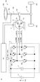
- FIG. 1 is a schematic configuration diagram of an AC rotary electric machine 1, an inverter 4, and a control device 10 according to the present embodiment.
- the AC rotary electric machine 1 is the driving force source of the electric power steering device 100
- the AC rotary electric machine 1, the inverter 4, and the control device 10 constitute the electric power steering device 100.
- AC rotary electric machine 1 The AC rotary electric machine 1 has three-phase windings Cu, Cv, and Cw of U phase, V phase, and W phase.
- the AC rotary electric machine 1 includes a stator and a rotor arranged radially inside the stator. Three-phase windings Cu, Cv, and Cw are wound around the stator.
- the rotor is provided with a permanent magnet, which is a permanent magnet type synchronous rotating machine.
- the three-phase windings may be star-connected or delta-connected.
- the rotor is provided with a rotation detection circuit 2 for detecting the rotation angle of the rotor.
- a resolver, an encoder, an MR sensor, or the like is used in the rotation detection circuit 2.
- the output signal of the rotation detection circuit 2 is input to the control device 10.
- the inverter 4 is a series circuit (leg) in which the switching element SP on the positive electrode side connected to the positive electrode side of the DC power supply 3 and the switching element SN on the negative electrode side connected to the negative electrode side of the DC power supply 3 are connected in series. Three sets are provided corresponding to each of the three phases. Then, the connection point of the two switching elements in the series circuit of each phase is connected to the winding of the corresponding phase.
- the switching element SPu on the positive electrode side of the U phase and the switching element SNu on the negative electrode side of the U phase are connected in series, and the connection point of the two switching elements is the winding of the U phase. It is connected to Cu.
- the switching element SPv on the positive electrode side of the V phase and the switching element SNv on the negative electrode side of the V phase are connected in series, and the connection points of the two switching elements are connected to the winding Cv of the V phase.
- the switching element SPw on the positive electrode side of W and the switching element SNw on the negative electrode side of W phase are connected in series, and the connection points of the two switching elements are connected to the winding Cw of W phase. ..
- the smoothing capacitor 5 is connected between the positive electrode side and the negative electrode side of the DC power supply 3.
- an IGBT Insulated Gate Bipolar Transistor
- MOSFET Metal Oxide Semiconductor Field Effect Transistor
- bipolar transistor in which diodes are connected in anti-parallel connection, etc.
- the gate terminal of each switching element is connected to the control device 10 via a gate drive circuit or the like.
- Each switching element is turned on or off by the switching signals GPU to GNw output from the control device 10.
- the DC power supply 3 outputs a DC voltage Vdc to the inverter 4.
- the DC voltage Vdc is set to 12V.
- the DC power supply 3 may be any device as long as it is a device that outputs a DC voltage Vdc, such as a battery, a DC-DC converter, a diode rectifier, and a PWM rectifier.
- the DC power supply 3 may be provided with a voltage sensor for detecting the DC voltage Vdc, and the output signal of the voltage sensor may be input to the control device 10.
- the control device 10 may perform control using the detected DC voltage Vdc.
- the electric power steering device 100 includes a control device 10 of an AC rotary electric machine, an inverter 4, an AC rotary electric machine 1, and a driving force transmission mechanism 101 that transmits the driving force of the AC rotary electric machine 1 to the steering device 102 of the vehicle. I have.
- the rotating shaft of the rotor of the AC rotary electric machine 1 is connected to the steering device 102 of the wheel 103 via the driving force transmission mechanism 101.
- the electric power steering device 100 is attached to a handle 104 in which the driver rotates left and right, a shaft 105 connected to the handle 104 and transmitting the steering torque of the handle 104 to the steering device 102 of the wheel 103, and the shaft 105. It is provided with a torque sensor 106 that detects the steering torque Ts by the handle 104, and a driving force transmission mechanism 101 such as a worm gear mechanism that connects the rotating shaft of the AC rotary electric machine 1 to the shaft 105.
- the output signal of the torque sensor 106 is input to the control device 10 (input circuit 92).
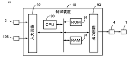
- Control device 10 The control device 10 controls the AC rotary electric machine 1 via the inverter 4. As shown in FIG. 2, the control device 10 includes a rotation detection unit 31, a voltage command calculation unit 32, a zero-phase voltage value calculation unit 33, a voltage command correction unit 34, a PWM control unit 35, and the like. Each function of the control device 10 is realized by a processing circuit provided in the control device 10. Specifically, as shown in FIG. 3, the control device 10 includes an arithmetic processing unit 90 (computer) such as a CPU (Central Processing Unit), a storage device 91 for exchanging data with the arithmetic processing unit 90, as a processing circuit. The arithmetic processing unit 90 includes an input circuit 92 for inputting an external signal, an output circuit 93 for outputting a signal from the arithmetic processing unit 90 to the outside, and the like.
- arithmetic processing unit 90 computer
- the arithmetic processing unit 90 includes an input circuit 92 for inputting an external signal, an output circuit 93 for outputting
- the arithmetic processing device 90 is provided with an ASIC (Application Specific Integrated Circuit), an IC (Integrated Circuit), a DSP (Digital Signal Processor), an FPGA (Field Programmable Gate Array), various logic circuits, and various signal processing circuits. You may. Further, as the arithmetic processing unit 90, a plurality of the same type or different types may be provided, and each processing may be shared and executed.
- the storage device 91 includes a RAM (RandomAccessMemory) configured to be able to read and write data from the arithmetic processing unit 90, a ROM (ReadOnlyMemory) configured to be able to read data from the arithmetic processing unit 90, and the like. Has been done.
- the input circuit 92 includes an A / D converter and the like to which various sensors and switches such as a rotation detection circuit 2 and a torque sensor 106 are connected and the output signals of these sensors and switches are input to the arithmetic processing device 90.
- the output circuit 93 is provided with a drive circuit or the like to which an electric load such as a gate drive circuit for driving the switching element on and off is connected and a control signal is output from the arithmetic processing device 90 to these electric loads.
- the arithmetic processing unit 90 executes software (program) stored in the storage device 91 such as a ROM, and the storage device 91 and the input circuit 92. , And by cooperating with other hardware of the control device 10 such as the output circuit 93.
- the setting data such as n zero-phase candidate voltage values Vzc_1 to Vzc_n and the switching cycle Tv used by the control units 31 to 35 and the like are stored in a storage device 91 such as a ROM as a part of the software (program). ing.
- a storage device 91 such as a ROM
- the rotation detection unit 31 detects the magnetic pole position ⁇ (rotation angle ⁇ of the rotor) and the rotation angular velocity ⁇ of the rotor at the electric angle. In the present embodiment, the rotation detection unit 31 detects the magnetic pole position ⁇ (rotation angle ⁇ ) and the rotation angular velocity ⁇ of the rotor based on the output signal of the rotation detection circuit 2.
- the magnetic pole position ⁇ is set in the direction of the north pole of the permanent magnet provided in the rotor.
- the rotation detection unit 31 is configured to estimate the rotation angle (pole position) based on the current information obtained by superimposing the harmonic component on the current command value without using the rotation sensor. It is also good (so-called sensorless method).
- the voltage command calculation unit 32 calculates the three-phase voltage command values Vub, Vvb, and Vwb to be applied to the three-phase winding.
- the voltage command calculation unit 32 detects the steering torque Ts of the driver based on the output signal of the torque sensor 106.
- the voltage command calculation unit 32 calculates the three-phase voltage command values Vub, Vvb, and Vwb based on the steering torque Ts and the magnetic pole position ⁇ .
- the voltage command calculation unit 32 sets the current command value Iqo on the q-axis based on the steering torque Ts, and sets the current command value Ido on the d-axis to 0.
- Ka is a constant, but may be changed according to the steering torque Ts, the traveling speed of the vehicle, and the like.
- the current command value Iqo on the q-axis may be set based on known compensation control according to the steering condition.
- the d-axis and q-axis current command values Ido and Iqo may be determined by a known vector control method such as maximum torque current control and weak magnetic flux control.
- the d-axis is set in the direction of the magnetic pole position ⁇ (N pole), and the q-axis is set in the direction advanced by 90 ° in electrical angle from the d-axis.
- the voltage command calculation unit 32 sets the d-axis and q-axis current command values Ido and Iqo to the specifications of the AC rotary electric machine 1 (winding resistance value R, d-axis inductance Ld, q-axis). Based on the inductance Lq, the interlinkage magnetic flux ⁇ ) by the permanent magnet, and the rotation angle velocity ⁇ , the voltage command value Vdo on the d-axis and the voltage command value Vqo on the q-axis are converted.
- Vdo R x Ido- ⁇ x Lq x Iqo
- Vqo R ⁇ Iqo- ⁇ ⁇ (Ld ⁇ Ido + ⁇ ) ⁇ ⁇ ⁇ (1-2)
- the voltage command calculation unit 32 performs fixed coordinate conversion and two-phase three-phase conversion on the voltage command values Vdo and Vqo on the d-axis and the q-axis based on the magnetic pole position ⁇ . It is converted into three-phase voltage command values Vub, Vvb, and Vwb.
- the voltage command calculation unit 32 may apply known modulation such as third-order harmonic superposition to the three-phase voltage command values Vub, Vvb, and Vwb.
- ⁇ Zero-phase voltage value calculation unit 33 The zero-phase voltage value calculation unit 33 sequentially switches n zero-phase candidate voltage values Vzc_1, Vzc_2, ... Vzc_n having different values (n is a natural number of 2 or more) for each switching cycle Tv, and the zero-phase voltage. Calculated as the value Vz.
- the set values of n zero-phase candidate voltage values Vzc_1 to Vzc_n will be described later.
- the zero-phase voltage value calculation unit 33 refers to the zero-phase candidate voltage value table data in which 80 zero-phase candidate voltage values Vzc_1 to Vzc_80 are set in advance, and the first zero-phase candidate voltage value for each switching cycle Tv.
- the 80th zero-phase candidate voltage value Vzc_80 is sequentially selected from Vzc_1, and the selected zero-phase candidate voltage value Vzzc is calculated as the zero-phase voltage value Vz.
- the first zero-phase candidate voltage value Vzc_1 is selected.
- the voltage command correction unit 34 corrects the three-phase voltage command values Vub, Vvb, and Vwb based on the zero-phase voltage value Vz.
- the voltage command correction unit 34 adds the zero-phase voltage value Vz to each of the three-phase voltage command values Vub, Vvb, and Vwb as shown in the following equation, and the corrected three-phase.
- the voltage command values Vuc, Vvc, and Vwc of are calculated.
- Vuc Vub + Vz
- Vvc Vvb + Vz ... (1-4)
- Vwc Vwb + Vz
- the PWM control unit 35 controls on / off of a plurality of switching elements of the inverter 4 based on the corrected three-phase voltage command values Vuc, Vvc, and Vwc by the voltage command correction unit 34.
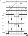
- the PWM control unit 35 compares the carrier wave CA vibrating in the PWM cycle Tc with each of the corrected three-phase voltage command values Vuc, Vvc, and Vwc, and turns on and off a plurality of switching elements based on the comparison result. Control.
- the carrier wave CA is a triangular wave that vibrates with an amplitude of Vdc / 2, which is half the DC voltage, centered on 0 in the PWM period Tc.
- the PWM control unit 35 turns on the switching signal GP of the switching element on the positive electrode side (1 in this example) to switch the switching element on the positive electrode side.
- the switching signal GP of the switching element on the positive electrode side is turned off (0 in this example), and the switching element on the positive electrode side is turned off.
- the PWM control unit 35 turns off the switching signal GN of the switching element on the negative electrode side (0 in this example) to switch on the negative electrode side.
- the switching element on the negative electrode side is turned off, and the carrier wave CA exceeds the voltage command value, the switching signal GN of the switching element on the negative electrode side is turned on (1 in this example) to turn on the negative electrode. Turn on the switching element on the side.
- a short-circuit prevention period in which both the switching element on the positive electrode side and the switching element on the negative electrode side are turned off. May be provided.
- FIG. 6 shows an example of PWM control after addition of the zero-phase voltage value Vz.
- the switching cycle Tv of the zero-phase voltage value Vz is set to be the same as the PWM cycle Tc, and the zero-phase voltage value Vz is switched at the timing of the apex of the valley of the carrier wave CA.
- the switching cycle Tv may be set differently from the PWM cycle Tc.
- the switching cycle Tv may be set to a natural number multiple of the PWM cycle Tc, or may be set to a natural number multiple of the half cycle of the PWM cycle Tc.
- the zero-phase voltage value Vz is set in order.
- the three-phase voltage command values Vub, Vvb, and Vwb are set to 0. Therefore, the three-phase voltage command values Vuc, Vvc, and Vwc after the addition of the zero-phase voltage value Vz are all the same value.
- the voltage command values Vuc, Vvc, Vwc of the three phases after addition are compared with the carrier wave CA, and switching signals on the positive electrode side and the negative electrode side of the three phases are generated.
- a DC voltage Vdc is applied to the three-phase winding when the switching signal on the positive electrode side of the three phase is on, and 0V is applied when the switching signal on the positive electrode side of the three phase is off.
- FIG. 6 shows the applied voltages Vu_PWM, Vv_PWM, and Vw_PWM applied to the three-phase windings.
- the three-phase voltage command values Vub, Vvb, and Vwb are constant values, by adding the zero-phase voltage values Vz, each of the reference timings tb_1, tb_2, and tb_3 at the peak of the valley of the carrier wave CA.
- the period of timing when the applied voltage Vu_PWM, Vv_PWM, Vw_PWM of the phase is cut from 0V to the DC voltage Vdc, and the timing when the applied voltages Vu_PWM, Vv_PWM, Vw_PWM of each phase are cut from 0V to the DC voltage Vdc.
- the periods ⁇ toff_1, ⁇ toff_2, and ⁇ toff_3 fluctuate equally in three phases.
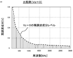
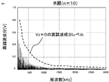
- FIG. 7 shows the frequency analysis result of the applied voltage Vu_PWM of the U-phase winding when the zero-phase voltage value Vz is always set to 0, that is, when the zero-phase voltage value Vz is not added (frequency range of analysis: 150 kHz to 3000 kHz).
- the dotted line is the level of the harmonic component connecting the levels of each component. In order to reduce the noise generated by the inverter 4, it is necessary to reduce the level of this high frequency component.
- FIG. 8 shows the frequency analysis result of the applied voltage Vu_PWM of the U-phase winding when the zero-phase voltage values Vz based on the 80 zero-phase candidate voltage values of FIG. 4 are added.
- the level of the harmonic component when the zero-phase voltage value Vz shown in FIG. 7 is not added is shown by a dotted line. From the figure, the on-timing and off-timing of the applied voltage fluctuate equally in all phases due to the addition of the zero-phase voltage value Vz, so that the harmonic components are reduced in many bands from 150 kHz to 3000 kHz, compared to the inverter 4.
- the generated noise (EMI) can be reduced.
- FIG. 9 is a measurement result of the noise sensitivity characteristic with respect to the winding current measured by the AC rotary electric machine 1 for the electric power steering device.
- a peak exists in the vicinity of 2500 Hz. This is because the mechanical resonance frequency of the frame of the AC rotary electric machine 1 is around 2500 Hz (resonance period Tm is 400 ⁇ s).
- the mechanical resonance of the AC rotary electric machine 1 is caused by the frame of the AC rotary electric machine 1, the power pack in which the AC rotary electric machine 1, the inverter 4, and the control device 10 are integrated, or the frame or the power pack and the gear mechanism. It occurs in power devices and the like including.
- the component of the frequency close to the mechanical resonance frequency of the AC rotary electric machine 1 tends to be noise of the AC rotary electric machine 1. .. Therefore, it is desired to reduce the component of the mechanical resonance period Tm of the AC rotary electric machine 1 included in the zero-phase voltage value Vz.
- n zero-phase candidate voltage values in the present application is based on the following concept A.
- Way of thinking A As shown in the following equation, the effective value Vzdif_rms of the zero-phase time delay deviation value Vzdif is smaller than the effective value VzAC_rms of the AC component VzAC of the zero-phase voltage value Vz for the n zero-phase candidate voltage values Vzc_1 to Vzc_n. It is set in advance so as to be.
- the effective value VzAC_rms of the AC component VzAC of the zero-phase voltage value is the square root of the value obtained by averaging the squared value of the AC component VzAC of the zero-phase voltage value in one cycle Tvn, as shown in the following equation.
- t is time.
- the zero-phase time delay deviation value Vzdif is the time in which the zero-phase voltage value Vz and the zero-phase voltage value Vz are delayed by j times the switching cycle Tv (j is a natural number of 1 or more) as shown in the following equation. It is the deviation from the delayed zero-phase voltage value.
- j is set to a natural number that minimizes the difference between the half-cycle Tm / 2 of the mechanical resonance cycle of the AC rotary electric machine and the j-fold value of the switching cycle Tv.
- the effective value Vzdif_rms of the zero-phase time-delayed deviation value Vzdif is the square root of the squared value of the zero-phase time-delayed deviation value Vzdif averaged over a round period Tvn.
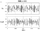
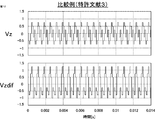
- the upper part of FIG. 10 shows the zero-phase voltage values Vz (t) in which the 80 zero-phase candidate voltage values shown in FIG. 4 are sequentially output in the switching cycle Tv.
- the time delay zero in which the zero-phase voltage value Vz (t) is delayed by j times the switching cycle Tv (100 ⁇ s ⁇ 2 200 ⁇ s in this example) from the zero-phase voltage value Vz (t).
- the zero-phase time delay deviation value Vzdif (t) obtained by subtracting the phase voltage value Vz (t-200 ⁇ s) is shown.
- Vzdif_rms the effective value Vzdif_rms of the zero-phase time delay deviation value Vzdif (t) in the lower part of FIG. 10 is calculated using the equation (1-8)
- Vzdif_rms 0.329V. Therefore, as shown in the equation (1-5), 80 zero-phase candidate voltage values are set so that VzAC_rms> Vzdif_rms, and the above concept A is satisfied.
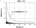
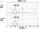
- the upper part of FIG. 11 shows the frequency analysis result of the zero-phase voltage value Vz in the upper part of FIG. 10, and the lower part of FIG. 11 shows the frequency analysis result of the zero-phase time delay deviation value Vzdif in the lower part of FIG.
- the components of the mechanical resonance frequency (near 2500 Hz) included in the zero-phase voltage value Vz and the zero-phase time delay deviation value Vzdif are small.
- the component of the mechanical resonance period Tm of the AC rotary electric machine 1 included in the zero-phase voltage value Vz can be reduced, and the noise of the AC rotary electric machine 1 can be reduced.
- the upper part of FIG. 12 shows the zero-phase voltage value Vz (t) when the seven zero-phase candidate voltage values of Patent Document 3 are used, and the lower part of FIG. 12 shows the zero-phase voltage value Vz (t).
- the zero-phase voltage value Vz (t) is delayed by 200 ⁇ s, and the zero-phase voltage value Vz (t-200 ⁇ s) is subtracted to show the zero-phase time-delay deviation value Vzdif (t).
- VzAC_rms 0.500V.
- Vzdif_rms 0.7789V of the zero-phase time delay deviation value Vzdif (t) in the lower part of FIG. Therefore, VzAC_rms ⁇ Vzdif_rms, which does not satisfy the above idea A.
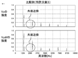
- the upper part of FIG. 13 shows the frequency analysis result of the zero-phase voltage value Vz of Patent Document 3 in the upper part of FIG. 12, and the lower part of FIG. 11 shows the zero-phase time delay deviation value Vzdif of Patent Document 3 in the lower part of FIG.
- the frequency analysis result is shown.
- the components of the mechanical resonance frequency (near 2500 Hz) included in the zero-phase voltage value Vz and the zero-phase time delay deviation value Vzdif are large.
- the component of the mechanical resonance period Tm of the AC rotary electric machine 1 included in the zero-phase voltage value Vz is large, and the noise of the AC rotary electric machine 1 is increased.
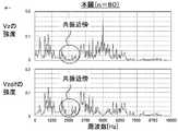
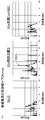
- FIG. 14 shows the actual measurement results of the noise level when the setting of the zero-phase voltage value Vz is changed in the AC rotary electric machine 1 for the electric power steering device having the sensitivity characteristic of FIG.
- the right side of FIG. 14 is the case of the zero-phase voltage value Vz (t) based on the 80 zero-phase candidate voltage values of FIG. In the case of Patent Document 3 which does not satisfy the concept A in the center of FIG.
- the mechanical resonance frequency band of the AC rotary electric machine 1 is included. In many frequency bands, the noise of the AC rotary electric machine 1 can be reduced.
- n zero-phase candidate voltage values may be set so as to satisfy the idea A, and are not limited to the 80 zero-phase candidate voltage values in FIG. Specific examples will be described below.
- the upper part of FIG. 16 shows the frequency analysis result of the zero-phase voltage value Vz in the upper part of FIG. 15, and the lower part of FIG. 16 shows the frequency analysis result of the zero-phase time delay deviation value Vzdif in the lower part of FIG.
- the components of the mechanical resonance frequency (near 2500 Hz) included in the zero-phase voltage value Vz and the zero-phase time delay deviation value Vzdif are small.
- the component of the mechanical resonance period Tm of the AC rotary electric machine 1 included in the zero-phase voltage value Vz can be reduced, and the noise of the AC rotary electric machine 1 can be reduced.
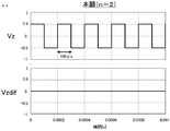
- FIG. 17 shows the frequency analysis result of the applied voltage Vu_PWM of the U-phase winding when the zero-phase voltage value Vz based on the two zero-phase candidate voltage values is added.
- the level of the harmonic component when the zero-phase voltage value Vz shown in FIG. 7 is not added is shown by a dotted line. From the figure, since the on-timing and off-timing of the applied voltage fluctuate equally in all phases due to the addition of the zero-phase voltage value Vz, the harmonic component is reduced in many bands from 150 kHz to 3000 kHz, compared to the inverter 4. The generated noise can be reduced. Since the concept A is satisfied, the noise of the AC rotary electric machine 1 can be reduced in many frequency bands including the mechanical resonance frequency band of the AC rotary electric machine 1.
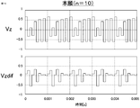
- the zero-phase voltage value calculation unit 33 sequentially selects from the first zero-phase candidate voltage value Vzc_1 to the tenth zero-phase candidate voltage value Vzc_10 for each switching cycle Tv, and zeros the selected zero-phase candidate voltage value Vzc. Calculated as the phase voltage value Vz. After the tenth zero-phase candidate voltage value Vzc_1, the first zero-phase candidate voltage value Vzc_1 is selected.
- VzAC_rms 5.07V
- Vzdif_rms the effective value of the zero-phase time delay deviation value Vzdif (t) in the lower part of FIG. VzAC_rms> Vzdif_rms, and the idea A is satisfied.
- the upper part of FIG. 20 shows the frequency analysis result of the zero-phase voltage value Vz in the upper part of FIG. 19, and the lower part of FIG. 20 shows the frequency analysis result of the zero-phase time delay deviation value Vzdif in the lower part of FIG.
- the components of the mechanical resonance frequency (near 2500 Hz) included in the zero-phase voltage value Vz and the zero-phase time delay deviation value Vzdif are small.
- the component of the mechanical resonance period Tm of the AC rotary electric machine 1 included in the zero-phase voltage value Vz can be reduced, and the noise of the AC rotary electric machine 1 can be reduced.
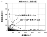
- FIG. 21 shows the frequency analysis result of the applied voltage Vu_PWM of the U-phase winding when the zero-phase voltage value Vz based on the ten zero-phase candidate voltage values is added.
- the level of the harmonic component when the zero-phase voltage value Vz shown in FIG. 7 is not added is shown by a dotted line. From the figure, since the on-timing and off-timing of the applied voltage fluctuate equally in all phases due to the addition of the zero-phase voltage value Vz, the harmonic component is reduced in many bands from 150 kHz to 3000 kHz, compared to the inverter 4. The generated noise can be reduced. Further, since the concept A is satisfied, the noise of the AC rotary electric machine 1 can be reduced in many frequency bands including the mechanical resonance frequency band of the AC rotary electric machine 1.
- the zero-phase voltage value calculation unit 33 sequentially selects from the first zero-phase candidate voltage value Vzc_1 to the 40th zero-phase candidate voltage value Vzc_40 for each switching cycle Tv, and zeros the selected zero-phase candidate voltage value Vzc. Calculated as the phase voltage value Vz. After the 40th zero-phase candidate voltage value Vzc_40, the first zero-phase candidate voltage value Vzc_1 is selected.
- VzAC_rms 3.94V
- Vzdif_rms the effective value of the zero-phase time delay deviation value Vzdif (t) in the lower part of FIG. VzAC_rms> Vzdif_rms, and the idea A is satisfied.
- the upper part of FIG. 24 shows the frequency analysis result of the zero-phase voltage value Vz in the upper part of FIG. 23, and the lower part of FIG. 24 shows the frequency analysis result of the zero-phase time delay deviation value Vzdif in the lower part of FIG.
- the components of the mechanical resonance frequency (near 2500 Hz) included in the zero-phase voltage value Vz and the zero-phase time delay deviation value Vzdif are small.
- the component of the mechanical resonance period Tm of the AC rotary electric machine 1 included in the zero-phase voltage value Vz can be reduced, and the noise of the AC rotary electric machine 1 can be reduced.
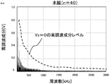
- FIG. 25 shows the frequency analysis result of the applied voltage Vu_PWM of the U-phase winding when the zero-phase voltage value Vz based on the 40 zero-phase candidate voltage values is added.
- the level of the harmonic component when the zero-phase voltage value Vz shown in FIG. 7 is not added is shown by a dotted line. From the figure, since the on-timing and off-timing of the applied voltage fluctuate equally in all phases due to the addition of the zero-phase voltage value Vz, the harmonic component is reduced in many bands from 150 kHz to 3000 kHz, compared to the inverter 4. The generated noise can be reduced. Further, since the concept A is satisfied, the noise of the AC rotary electric machine 1 can be reduced in many frequency bands including the mechanical resonance frequency band of the AC rotary electric machine 1.
- An object of the present application is to reduce the noise (EMI) generated by the inverter 4 and to reduce the noise of the AC rotary electric machine 1. Therefore, in the present application, the machine of the AC rotary electric machine 1 included in the zero-phase voltage value Vz and the zero-phase time delay deviation value Vzdif by setting n zero-phase candidate voltage values so as to satisfy the idea A.
- the component of the target resonance period Tm can be reduced, and the noise of the AC rotary electric machine 1 can be reduced. From a plurality of specific examples, as n is increased, the component of 150 kHz to 3000 kHz included in the applied voltage of the winding tends to decrease.
- n zero-phase candidate voltage values are determined so as to satisfy the idea A, and the component of the mechanical resonance period Tm of the AC rotary electric machine 1 included in the zero-phase voltage value Vz is reduced. do. Then, the component of 150 kHz to 3000 kHz included in the applied voltage of the winding may satisfy the specification, but if it is not satisfied, n may be increased and it may be confirmed whether the specification is satisfied again. However, at least two n are required.
- FIG. 26 shows the frequency analysis result of the applied voltage Vu_PWM of the U-phase winding when all the 10 zero-phase candidate voltage values shown in FIG. 18 are doubled and used. Compared with FIG. 21 which is not doubled, in FIG. 26 which is doubled, the harmonic component in the vicinity of approximately 300 kHz to 500 kHz is reduced. Therefore, adjusting the amplitudes of n zero-phase candidate voltage values is effective for adjusting the noise level.
- the maximum value among the n zero-phase candidate voltage values and the minimum value among the n zero-phase candidate voltage values are used.
- the n zero-phase candidate voltage values may be preset so that the difference is 10% or more of the DC voltage Vdc supplied to the inverter.
- N zero-phase candidate voltage values may be preset so as to be 5% or more of the supplied DC voltage Vdc.
- the mechanical resonance period Tm of the AC rotary electric machine 1 for the electric power steering device according to the present application is within the range of 200 ⁇ s or more and 500 ⁇ s or less (mechanical resonance frequency is 2 kHz or more and 5 kHz or less). More preferably, the mechanical resonance period Tm is in the range of 300 ⁇ s or more and 400 ⁇ s or less (mechanical resonance frequency is 2.5 kHz or more and 3.3 kHz or less). Further, when the PWM cycle Tc is 60 ⁇ s or less and 6.67 ⁇ s or more, it is suitable for use in the electric power steering device 100 that reduces noise and reduces noise of the AC rotary electric machine 1.
- the PWM cycle Tc is 60 ⁇ s or less and 6.67 ⁇ s or more
- the PWM frequency (1 / Tc) becomes 16 kHz or more and 150 kHz or less
- the noise reduction effect is lowered at 150 kHz or more
- AC rotation is performed at less than 16 kHz. Since the sound of the PWM frequency component of the electric machine 1 is conspicuous, the noise in the human audible range is exacerbated.
- FIG. 27 is a schematic configuration diagram of an AC rotary electric machine 1, an inverter 4, and a control device 10 according to the present embodiment.
- the three-phase series circuit of the inverter 4 has a U-phase resistor Ru, a V-phase resistor Rv, and a W-phase resistor Rw connected in series to the switching element SN on the negative electrode side of each phase.
- the resistors Ru, Rv, and Rw of each phase are connected in series to the negative electrode side of the switching element SN on the negative electrode side.
- the three-phase resistors Ru, Rv, and Rw are shunt resistors for current detection, and the amplifiers 21, 22, and 23 detect the potential difference between both ends of the resistance of each phase, and control the potential difference between both ends. It is input to the device 10. Therefore, the inverter 4 of the present embodiment is a so-called lower arm 3 shunt type inverter.
- the resistance of each phase may be connected in series to the switching element SP on the positive electrode side.
- a resistor may be connected in series to the bus on the positive electrode side or the bus on the negative electrode side that connects the inverter 4 and the DC power supply 3.
- the voltage command calculation unit 32 detects the currents Iud, Ivd, and Iwd flowing in the windings of each phase based on the potential differences between the resistors Ru, Rv, and Rw of each phase. Then, as shown in the following equation, the voltage command calculation unit 32 performs three-phase two-phase conversion and rotational coordinate conversion on the three-phase current detection values Iud, Ivd, and Iwd based on the magnetic pole position ⁇ , and the d-axis. It is converted into the current detection value Idd and the current detection value Iqd of the q-axis.
- the voltage command calculation unit 32 calculates the bus current based on the potential difference between both ends of the resistor. Using a known method for detection, the winding currents Iud, Ivd, and Iwd of each phase are detected based on the on / off pattern of the switching element of each phase at the time when the bus current is detected and the bus current.
- the voltage command calculation unit 32 detects the steering torque Ts of the driver based on the output signal of the torque sensor 106. As shown in the equation (1-1), the voltage command calculation unit 32 sets the current command value Iqo on the q-axis based on the steering torque Ts, and sets the current command value Ido on the d-axis to 0.
- the voltage command calculation unit 32 receives the three-phase voltage command values Vub, Vvb, so that the current detection values Idd and Iqd on the d-axis and the q-axis approach the current command values Ido and Iqo on the d-axis and the q-axis. Change Vwb. As shown in the following equation, the voltage command calculation unit 32 changes the voltage command value Vdo of the d-axis by PI control so that the current detection value Idd of the d-axis approaches the current command value Ido of the d-axis, and the q-axis.
- the voltage command value Vqo of the q-axis is changed by PI control so that the current detection value Iqd of the above approaches the current command value Iqo of the q-axis.
- feedforward control such as for non-interference between the d-axis current and the q-axis current may be performed.
- Kd and Kq are proportional gains
- Td and Tq are integral time constants
- s is a Laplace operator.
- the voltage command calculation unit 32 sets the voltage command values Vdo and Vqo of the d-axis and the q-axis based on the magnetic pole position ⁇ as shown in the equation (1-3). Fixed coordinate conversion and two-phase three-phase conversion are performed to convert to three-phase voltage command values Vub, Vvb, and Vwb.
- the zero-phase voltage value calculation unit 33 sequentially switches n zero-phase candidate voltage values Vzc_1 to Vzc_n having different values (n is a natural number of 2 or more) in each switching cycle Tv. Calculated as the zero-phase voltage value Vz.
- the n zero-phase candidate voltage values Vzc_1 to Vzc_n are preset so as to satisfy the idea A.
- the voltage command correction unit 34 corrects the three-phase voltage command values Vub, Vvb, and Vwb based on the zero-phase voltage value Vz. As shown in the equation (1-4), the voltage command correction unit 34 adds the zero-phase voltage value Vz to each of the three-phase voltage command values Vub, Vvb, and Vwb to obtain the corrected three-phase voltage. The voltage command values Vuc, Vvc, and Vwc are calculated.
- the PWM control unit 35 controls on / off of a plurality of switching elements of the inverter 4 based on the corrected three-phase voltage command values Vuc, Vvc, and Vwc.
- ⁇ Current detection timing> The current detection timing based on the potential difference between both ends of the resistor will be described.
- the U-phase winding current Iu can be detected at any timing as long as the switching element SNu on the negative electrode side of the U-phase is on.
- the detection of the winding current Iv of the V phase can be performed at any timing as long as the switching element SNv on the negative electrode side of the V phase is on.
- the detection of the winding current Iw of the W phase can be performed at any timing as long as the switching element SNw on the negative electrode side of the W phase is on.
- the voltage command calculation unit 32 determines each phase at the timing of the peak of the peak of the carrier wave, based on the potential difference between the resistors Ru, Rv, and Rw of each phase. The currents Iud, Ivd, and Iwd flowing through the windings of the above are detected.
- the voltage command calculation unit 32 determines the resistors Ru, Rv of each phase at the timing of the peak of the valley of the carrier wave.
- Rw is configured to detect currents Iud, Ivd, Iwd flowing through the windings of each phase based on the potential difference between both ends.
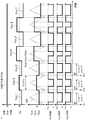
- FIG. 28 shows the control behavior for three cycles of the PWM cycle Tc. Similar to the first embodiment, the switching cycle Tv of the zero-phase voltage value Vz is set to be the same as the PWM cycle Tc, and the zero-phase voltage value Vz is switched at the timing of the apex of the valley of the carrier wave CA. There is.
- the first zero-phase candidate voltage value Vzc_1, the second zero-phase candidate voltage value Vzc_2, and the third zero-phase candidate voltage value Vzc_3 are sequentially set to the zero-phase voltage value Vz in each switching cycle Tv. Has been done.
- the three-phase voltage command values Vub, Vvb, and Vwb are set to different values. Therefore, the three-phase voltage command values Vuc, Vvc, and Vwc after the addition of the zero-phase voltage value Vz have different values, and change according to the change of the zero-phase voltage value Vz for each switching cycle Tv. ..
- FIG. 28 shows the current Iu flowing in the U-phase winding, the current Iv flowing in the V-phase winding, and the current Iw flowing in the W-phase winding. Further, the moving average values Iu_ave, Iv_ave, and Iw_ave between the PWM cycles Tc of the currents Iu, Iv, and Iw of each phase are shown.
- the winding currents Iu, Iv, and Iw of each phase include a ripple component with respect to the average values Iu_ave, Iv_ave, and Iw_ave of the winding currents of each phase.
- the winding currents Iu, Iv, and Iw of each phase correspond to the average values Iu_ave, Iv_ave, and Iw_ave of the winding currents of each phase. Therefore, by setting the current detection timing to the apex of the peak of the carrier wave CA, the fundamental wave component of the rotation cycle can be detected from the winding current including the ripple component.
- the control of the AC rotary electric machine 1 for the electric power steering device it is required to detect the winding current with high accuracy.
- the detected value of the winding current having an error with respect to the true value is controlled so as to match the current command value, and the output of the AC rotary electric machine 1 is output.
- Torque ripple occurs in the torque. Torque ripple is transmitted to the steering wheel 104 via the shaft 105, which deteriorates the steering feeling of the driver.
- the fundamental wave can be detected from the winding current including the ripple component. Therefore, the winding current can be detected with high accuracy, the generation of torque ripple due to the current detection error is suppressed, and a good steering feeling of the steering wheel can be obtained by the driver.
- FIG. 29 shows an equivalent circuit of a series circuit for one phase of the inverter 4 when the resistor R is not provided.
- the switching element SP on the positive electrode side and the switching element SN on the negative electrode side are represented by switches, and conduction resistance is ignored.
- Vout_ave D ⁇ Vdc ⁇ ⁇ ⁇ (2-3)
- the line voltage is not affected by the addition of the zero-phase voltage value Vz.
- the resistor R is not provided, the winding current of the AC rotary electric machine 1 flows based on the line voltage, so that the influence of the zero-phase voltage value Vz does not appear in the winding current.
- FIG. 30 shows an equivalent circuit of a series circuit for one phase of the inverter 4 when the resistor R is provided.
- a resistor R is connected in series to the negative electrode side of the switching element SN on the negative electrode side.
- Vout_ave D x Vdc + (1-D) x (-R x I) ... (2-7)
- Voutu_ave (Du + ⁇ D) x Vdc + (1- (Du + ⁇ D)) x (-R x Iu)
- Voutv_ave (Dv + ⁇ D) x Vdc + (1- (Dv + ⁇ D)) x (-R x Iv) ... (2-9)
- the resistance when the switching element SN on the negative side is turned on such as the lower arm 3 shunt type inverter, the upper arm 3 shunt type inverter, and the bus 1 shunt type inverter as in this embodiment.
- the influence of the addition of the zero-phase voltage value Vz appears in the line voltage and winding current.
- FIG. 31 and 32 show the setting of the zero-phase voltage value Vz in the AC rotary electric machine 1 for the electric power steering device having the sensitivity characteristic of FIG. 9 in the lower arm 3 shunt type inverter according to the present embodiment.
- the actual measurement result of the noise level in the case of the case is shown.
- n zero-phase candidate voltage values are set so as to satisfy the idea A.
- Vz the zero-phase voltage value
- Embodiment 3 The AC rotary electric machine 1, the inverter 4, and the control device 10 according to the third embodiment will be described. The description of the same components as those in the first embodiment will be omitted.
- the basic configuration of the AC rotary electric machine 1, the inverter 4, and the control device 10 according to the present embodiment is the same as that of the first and second embodiments, but the control device 10 sets the command voltage vector and the zero-phase voltage. It differs from the first and second embodiments in that the command voltage vector is corrected based on the value Vz and the on / off control of the switching element is performed based on the corrected command voltage vector.
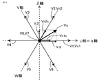
- the voltage command calculation unit 32 calculates a command voltage vector Vo in which the voltage applied to the three-phase winding is represented by a two-axis fixed coordinate system associated with the three-phase winding.
- the two-axis fixed coordinate system is set in the ⁇ -axis determined in the direction of the U-phase winding Cu and in the direction 90 ° ahead of the ⁇ -axis by the electric angle. It consists of a ⁇ axis.
- the magnetic pole position ⁇ is the angle of the d-axis with respect to the ⁇ -axis.
- the voltage command calculation unit 32 calculates the voltage command value Vdo on the d-axis and the voltage command value Vqo on the q-axis by using the same method as in the first or second embodiment.
- the voltage command calculation unit 32 performs fixed coordinate conversion of the voltage command value Vdo on the d-axis and the voltage command value Vqo on the q-axis based on the magnetic pole position ⁇ , as shown in the following equation. It is converted into the voltage command value V ⁇ on the ⁇ axis and the voltage command value V ⁇ on the ⁇ axis. The voltage vector represented by the voltage command value V ⁇ on the ⁇ axis and the voltage command value V ⁇ on the ⁇ axis becomes the command voltage vector Vo.
- the voltage command calculation unit 32 determines four on / off patterns of a plurality of switching elements to be set during the PWM cycle Tc based on the command voltage vector Vo, and determines the periods of the four on / off patterns in the PWM cycle Tc. do.
- the four on / off patterns determined include two on / off patterns corresponding to the zero voltage vector. This process is the same as the known space vector PWM.
- the on / off patterns of the plurality of switching elements of the inverter 4 that can be set are eight in total.
- “1” indicates that the switching element is turned on
- “0” indicates that the switching element is turned off.
- the eight on / off patterns correspond to the eight basic voltage vectors V0 to V7 shown in FIG. 33.
- the 0th basic voltage vector V0 is a zero voltage vector. That is, in the 0th basic voltage vector V0, the switching elements SPu, SPv, and SPw on the positive electrode side of the three phases are all turned off, and the switching elements SNu, SNv, and SNw on the negative electrode side of the three phases are all turned on. No DC voltage Vdc is applied to the phase windings.
- the seventh fundamental voltage vector V7 is a zero voltage vector. That is, in the 7th basic voltage vector V7, the switching elements SPu, SPv, and SPw on the positive electrode side of the three phases are all turned on, and the switching elements SNu, SNv, and SNw on the negative electrode side of the three phases are all turned off. No DC voltage Vdc is applied to the phase windings.
- the first fundamental voltage vector V1 is a vector in the direction of the U-phase winding
- the second fundamental voltage vector V2 is a vector in the direction opposite to the direction of the W-phase winding
- the third fundamental voltage vector V3 is.
- the fourth fundamental voltage vector V4 is the vector opposite to the U-phase winding direction
- the fifth fundamental voltage vector V5 is the W-phase winding direction. It becomes a vector
- the sixth fundamental voltage vector V6 becomes a vector in the direction opposite to the winding direction of the V phase.
- the voltage command calculation unit 32 has two fundamental voltage vectors (hereinafter, close to each other) that are close to the command voltage vector Vo from the six fundamental voltage vectors V1 to V6 excluding the zero voltage vectors 0 and 7 fundamental voltage vectors V0 and V7.
- the basic voltage vectors Vn1 and Vn2) are determined. Then, the voltage command calculation unit 32 sets the two determined proximity basic voltage vectors Vn1 and Vn2 and the 0th and 7th basic voltage vectors V0 and V7 during the PWM cycle Tc (hereinafter, four basic voltage vectors). , Set as the basic voltage vector).
- the first fundamental voltage vector V1 and the second fundamental voltage vector V2, which are close to the command voltage vector Vo, are determined as the two proximity fundamental voltage vectors Vn1 and Vn2.
- the voltage command calculation unit 32 decomposes the command voltage vector Vo into the components Vn1c and Vn2c of the two proximity basic voltage vectors Vn1 and Vn2. Then, as shown in the following equation, the voltage command calculation unit 32 has two proximity basic voltages in the PWM cycle Tc based on the respective magnitudes of the components Vn1c and Vn2c of the two proximity basic voltage vectors with respect to the DC voltage Vdc. The ratios Dn1 and Dn2 of the respective set periods of the vectors Vn1 and Vn2 are calculated.
- the magnitudes of the components Vn1c and Vn2c of the two proximity fundamental voltage vectors are calculated as follows based on the voltage command value V ⁇ on the ⁇ axis and the voltage command value V ⁇ on the ⁇ axis. To.
- the voltage command calculation unit 32 sets so that the ratios D0 and D7 of the respective setting periods of the 0th and 7th basic voltage vectors V0 and V7, which are the zero voltage vectors in the PWM cycle Tc, satisfy the following equation.
- D0 + D7 1- (Dn1 + Dn2) ... (3-4)
- the period other than the setting period of the two proximity basic voltage vectors Vn1 and Vn2 in the PWM cycle Tc can be arbitrarily allocated and set to the zero voltage vectors V0 and V7.
- the ratios D0 and D7 of the setting period of V0 and V7 are set evenly as in the following equation.
- the period obtained by multiplying each of the ratios Dn1, Dn2, D0, and D7 of the setting periods of the four setting basic voltage vectors by the PWM cycle Tc is the setting period of the four setting basic voltage vectors.
- ⁇ Zero-phase voltage value calculation unit 33 Similar to the first embodiment, the zero-phase voltage value calculation unit 33 sequentially switches n zero-phase candidate voltage values Vzc_1 to Vzc_n having different values (n is a natural number of 2 or more) in each switching cycle Tv. Calculated as the zero-phase voltage value Vz.
- the n zero-phase candidate voltage values Vzc_1 to Vzc_n are preset so as to satisfy the idea A.
- the voltage command correction unit 34 corrects the command voltage vector Vo based on the zero-phase voltage value Vz.
- the voltage command correction unit 34 sets the period of the two on / off patterns corresponding to the zero voltage vector (in this example, the setting period of the 0th and 7th basic voltage vectors V0 and V7) according to the zero-phase voltage value Vz. Change the total period of the two so that they do not change.
- the voltage command correction unit 34 divides the zero-phase voltage value Vz by the DC voltage Vdc to calculate the zero-phase voltage correction period ratio Dz.
- Dz Vz / Vdc ⁇ ⁇ ⁇ (3-6)
- the voltage command correction unit 34 adds the zero-phase voltage correction period ratio Dz to the ratio D0 of the setting period of the 0th fundamental voltage vector V0, and the corrected 0th fundamental voltage vector V0.
- the ratio D0c of the set period is calculated, the zero-phase voltage correction period ratio Dz is subtracted from the ratio D7 of the set period of the 7th fundamental voltage vector V7, and the ratio D7c of the set period of the 7th fundamental voltage vector V7 after correction is calculated.
- the period obtained by multiplying each of the corrected ratios D0c and D7c of the 0th and 7th fundamental voltage vectors by the PWM cycle Tc is the setting period of the 0th and 7th fundamental voltage vectors.
- the ratios Dn1 and Dn2 of the set periods of the two proximity basic voltage vectors Vn1 and Vn2 are not changed by the zero-phase voltage value Vz.
- the PWM control unit 35 has four on / off patterns (in this example, two proximity basic voltage vectors Vn1, Vn2, and 0th and 7th basic voltage vectors V0, V7) determined by the voltage command calculation unit 32, and a voltage.
- a plurality of switching elements are on / off controlled based on the period of four on / off patterns (Dn1, Dn2, D0c, D7c in this example) determined and corrected by the command calculation unit 32 and the voltage command correction unit 34.
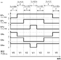
- the PWM control unit 35 has four set basic voltage vectors (Vn1, Vn2, V0, V7) set in the PWM cycle Tc and a ratio (Dn1, Dn2, D0c) of the set periods of the four set basic voltage vectors in the PWM cycle Tc. Based on D7c), switching signals GPu to GNw of each switching element are generated. For example, in the example of FIG. 33, as shown in FIG. 35, switching signals GPU to GNw of each switching element are generated.
- the voltage obtained by multiplying the switching signals GPu, GPv, GPw of the switching element on the positive electrode side of each phase by the DC voltage Vdc corresponds to the applied voltages Vu_PWM, Vv_PWM, Vw_PWM of the windings of each phase.
- the applied voltages Vu_PWM, Vv_PWM, and Vw_PWM of the windings of each phase are turned on and off.
- the timing fluctuates equally in all phases. Therefore, as in the first and second embodiments, the harmonic component of the applied voltage of the winding of each phase can be reduced in many bands of 150 kHz to 3000 kHz, and the noise generated by the inverter 4 can be reduced. can. Further, since the zero-phase voltage value Vz satisfies the concept A, the noise of the AC rotary electric machine 1 can be reduced in many frequency bands including the mechanical resonance frequency band of the AC rotary electric machine 1.
- the zero-phase voltage value calculation unit 33 may change the magnitude of the zero-phase voltage value Vz according to the amplitude of the voltage applied to the three-phase winding.
- the amplitude of the voltage applied to the three-phase winding is set to the amplitude of the fundamental wave components of the three-phase voltage command values Vub, Vvb, and Vwb.
- the amplitude of the voltage applied to the three-phase winding is set to the magnitude of the command voltage vector Vo.
- the zero-phase voltage value calculation unit 33 sets the gain according to the amplitude of the voltage applied to the three-phase winding, and switches n zero-phase candidate voltage values Vzc_1 to Vzc_n in order for each switching cycle Tv.
- the zero-phase voltage value Vz is set by multiplying the set voltage value by the gain. For example, the zero-phase voltage value calculation unit 33 reduces the gain as the amplitude of the voltage applied to the three-phase winding increases. Further, the zero-phase voltage value calculation unit 33 reduces the gain as the rotation speed of the AC rotary electric machine 1 increases.
- the zero-phase voltage value calculation unit 33 may change the magnitude of the zero-phase voltage value Vz according to the DC voltage Vdc.
- the zero-phase voltage value calculation unit 33 sets the gain according to the DC voltage Vdc, and the n zero-phase candidate voltage values Vzc_1 to Vzc_n are sequentially switched for each switching cycle Tv to obtain a gain.
- the AC rotary electric machine 1 may be a rotary electric machine provided with three-phase windings, for example, a field winding type synchronous rotary machine provided with an electromagnet in the rotor, or a permanent magnet in the rotor. It may be an induction machine that is not provided. Further, the AC rotary electric machine 1 may be a rotary electric machine provided with a plurality of sets of three-phase windings. The configuration of the present application can be applied to each set of three-phase windings.
- a current sensor may be provided on the electric wire connecting the inverter 4 and the three-phase winding.
- the AC rotary electric machine 1 may be used as a driving force source for various devices other than the electric power steering device 100.
- the AC rotary electric machine 1 may be used as a driving force source for wheels.
Landscapes
- Engineering & Computer Science (AREA)
- Power Engineering (AREA)
- Chemical & Material Sciences (AREA)
- Combustion & Propulsion (AREA)
- Transportation (AREA)
- Mechanical Engineering (AREA)
- Control Of Ac Motors In General (AREA)
- Power Steering Mechanism (AREA)
- Steering Control In Accordance With Driving Conditions (AREA)
Abstract
交流回転電機の機械的な共振周期を考慮し、ノイズを低減しつつ、交流回転電機の騒音の増加を抑制できる交流回転電機の制御装置及び電動パワーステアリング装置を提供する。n個の零相候補電圧値を、切換周期(Tv)毎に順番に切り替えて零相電圧値(Vz)として算出し、零相電圧値(Vz)により補正した電圧指令値に基づいて、スイッチング素子をオンオフ制御し、零相電圧値(Vz)と、零相電圧値(Vz)を切換周期(Tv)のj倍値だけ遅らせた値との偏差を零相時間遅れ偏差値(Vzdif)とし、jは、交流回転電機の機械的な共振周期(Tm)の半周期と、切換周期(Tv)のj倍値との差を最小にする自然数であり、n個の零相候補電圧値は、零相電圧値の交流成分の実効値(VzAC_rms)に比べて、零相時間遅れ偏差値の実効値(Vzdif_rms)が小さくなるように、予め設定されている交流回転電機の制御装置(10)。
Description
本願は、交流回転電機の制御装置及び電動パワーステアリング装置に関するものである。
特許文献1には、電気ノイズが小さい交流回転電機を提供するために、異なる周波数の複数のキャリア波を用意し、用意した複数のキャリア波から所定の時間毎にランダムに1つを選択し、選択したキャリア波を用いてPWM制御を行い、交流回転電機を駆動する技術が開示されている。
特許文献2には、スイッチング周波数のディザリングによるノイズ(EMI)の低減手法として、少なくとも1つのレジスタを含んでいる制御装置を用い、その動作パラメータに基づいてモータを制御するためにモータと信号通信する制御装置を提供する工程と、第1のクロック周波数を選択する工程と、第1のスイッチング周波数を選択する工程と、少なくとも1つのレジスタを初期化し、それにより、定められた少なくとも1つの数を設定する工程と、第1のホッピング期間を選択する工程と、少なくとも1つのレジスタの定められた少なくとも1つの数、第1のクロック周波数、及び第1のホッピング周波数に基づいて、パルス変調のスイッチング周波数をランダムに変調する工程と、を備える技術が開示されている。
特許文献3には、オフセット電圧を演算するオフセット電圧演算部と、3相の電圧指令値のそれぞれに等しくオフセット電圧を加算することによって、修正三相電圧指令値を出力する修正三相電圧指令値演算部と、を備え、オフセット電圧演算部は、オフセット電圧として、値が異なるn個のオフセット候補電圧を、設定された時間毎に切り替えて出力することにより、3相巻線への印加電圧のオンタイミング及びオフタイミングを等しく変動させ、ノイズ(EMI)を低減する技術が開示されている。
特許文献1及び特許文献2の技術には、以下(1)及び(2)の課題がある。
(1)キャリア波の周波数を複数用意して、その複数の周波数から1つを選択するような方法においては、複数のキャリア波を記憶する必要があり、複数の周波数のキャリア波に対応させてPWM制御を行う必要があるため、メモリー容量及び処理負荷が増加し、廉価なマイコン(CPU)への実装が容易でない。
(2)キャリア波を任意に変更できるように、マイコン(CPU)に実装することは容易でない。
(1)キャリア波の周波数を複数用意して、その複数の周波数から1つを選択するような方法においては、複数のキャリア波を記憶する必要があり、複数の周波数のキャリア波に対応させてPWM制御を行う必要があるため、メモリー容量及び処理負荷が増加し、廉価なマイコン(CPU)への実装が容易でない。
(2)キャリア波を任意に変更できるように、マイコン(CPU)に実装することは容易でない。
そこで、特許文献3においては、(1)、(2)の課題に対して、PWM制御そのものを変更することなく、処理の追加が容易なオフセット電圧の加算を用い、ノイズ(EMI)を低減している。
しかし、特許文献3の技術では、交流回転電機の機械的な共振周期の特性が考慮されておらず、値が異なるn個のオフセット候補電圧から順番に選択されたランダムなオフセット電圧の加算により、印加電圧に含まれる機械的な共振周期の成分が増大し、交流回転電機の騒音が増大されてしまう場合がある。特許文献3には、どのように、n個のオフセット候補電圧を設定すれば、交流回転電機の機械的な共振周期により、交流回転電機の騒音が増大しないようになるか記載されていない。
そこで、本願は、交流回転電機の機械的な共振周期を考慮し、ノイズ(EMI)を低減しつつ、交流回転電機の騒音の増加を抑制できる交流回転電機の制御装置及び電動パワーステアリング装置を提供することを目的とする。
本願に係る交流回転電機の制御装置は、3相の巻線が巻装されたステータとロータとを有する交流回転電機を、複数のスイッチング素子を有するインバータを介して制御する交流回転電機の制御装置であって、
前記3相の巻線に印加する3相の電圧指令値、又は前記3相の巻線に印加する電圧を、前記3相の巻線に関連付けた2軸の固定座標系で表した指令電圧ベクトルを算出する電圧指令算出部と、
値が異なるn個(nは2以上の自然数)の零相候補電圧値を、切換周期毎に順番に切り替えて零相電圧値として算出する零相電圧値算出部と、
前記零相電圧値に基づいて、前記3相の電圧指令値又は前記指令電圧ベクトルを補正する電圧指令補正部と、
前記電圧指令補正部による、補正後の前記3相の電圧指令値又は補正後の前記指令電圧ベクトルに基づいて、前記複数のスイッチング素子をオンオフ制御するPWM制御部と、を備え、
前記零相電圧値と、前記零相電圧値を前記切換周期のj倍値(jは1以上の自然数)だけ遅らせた時間遅れ零相電圧値との偏差を零相時間遅れ偏差値とし、
jは、前記交流回転電機の機械的な共振周期の半周期と、前記切換周期のj倍値との差を最小にする自然数であり、
前記n個の零相候補電圧値は、前記零相電圧値の交流成分の実効値に比べて、前記零相時間遅れ偏差値の実効値が小さくなるように、予め設定されているものである。
本願に係る電動パワーステアリング装置は、
上記の交流回転電機の制御装置と、
前記インバータと、
前記交流回転電機と、
前記交流回転電機の駆動力を車両の操舵装置に伝達する駆動力伝達機構と、を備え、
前記PWM制御部のPWM周期は、60μs以下に設定され、
前記交流回転電機の機械的な前記共振周期は、200μs以上、500μs以下の範囲内である。
上記の交流回転電機の制御装置と、
前記インバータと、
前記交流回転電機と、
前記交流回転電機の駆動力を車両の操舵装置に伝達する駆動力伝達機構と、を備え、
前記PWM制御部のPWM周期は、60μs以下に設定され、
前記交流回転電機の機械的な前記共振周期は、200μs以上、500μs以下の範囲内である。
n個の零相候補電圧値が、上記のように予め設定されることで、零相電圧値及び零相時間遅れ偏差値に含まれる機械的な共振周期の成分が小さくすることができ、共振による交流回転電機の騒音の増加を抑制することができる。よって、本願に係る交流回転電機の制御装置及び電動パワーステアリング装置によれば、ノイズ(EMI)を低減しつつ、交流回転電機の騒音の増加を抑制できる。
1.実施の形態1
実施の形態1に係る交流回転電機の制御装置10(以下、単に制御装置10と称す)について図面を参照して説明する。図1は、本実施の形態に係る交流回転電機1、インバータ4、及び制御装置10の概略構成図である。本実施の形態では、交流回転電機1が、電動パワーステアリング装置100の駆動力源となっており、交流回転電機1、インバータ4及び制御装置10が、電動パワーステアリング装置100を構成している。
実施の形態1に係る交流回転電機の制御装置10(以下、単に制御装置10と称す)について図面を参照して説明する。図1は、本実施の形態に係る交流回転電機1、インバータ4、及び制御装置10の概略構成図である。本実施の形態では、交流回転電機1が、電動パワーステアリング装置100の駆動力源となっており、交流回転電機1、インバータ4及び制御装置10が、電動パワーステアリング装置100を構成している。
1-1.交流回転電機1
交流回転電機1は、U相、V相、W相の3相の巻線Cu、Cv、Cwを有している。交流回転電機1は、ステータと、ステータの径方向内側に配置されたロータと、を備えている。ステータには、3相の巻線Cu、Cv、Cwが巻装されている。本実施の形態では、ロータには永久磁石が設けられており、永久磁石式の同期回転機とされている。3相の巻線は、スター結線されてもよいし、デルタ結線されてもよい。
交流回転電機1は、U相、V相、W相の3相の巻線Cu、Cv、Cwを有している。交流回転電機1は、ステータと、ステータの径方向内側に配置されたロータと、を備えている。ステータには、3相の巻線Cu、Cv、Cwが巻装されている。本実施の形態では、ロータには永久磁石が設けられており、永久磁石式の同期回転機とされている。3相の巻線は、スター結線されてもよいし、デルタ結線されてもよい。
ロータには、ロータの回転角度を検出するための回転検出回路2が備えられている。回転検出回路2には、レゾルバ、エンコーダ、MRセンサ等が用いられる。回転検出回路2の出力信号は、制御装置10に入力される。
1-2.インバータ4
インバータ4は、直流電源3の正極側に接続される正極側のスイッチング素子SPと直流電源3の負極側に接続される負極側のスイッチング素子SNとが直列接続された直列回路(レッグ)を、3相各相に対応して3セット設けている。そして、各相の直列回路における2つのスイッチング素子の接続点が、対応する相の巻線に接続されている。
インバータ4は、直流電源3の正極側に接続される正極側のスイッチング素子SPと直流電源3の負極側に接続される負極側のスイッチング素子SNとが直列接続された直列回路(レッグ)を、3相各相に対応して3セット設けている。そして、各相の直列回路における2つのスイッチング素子の接続点が、対応する相の巻線に接続されている。
具体的には、U相の直列回路では、U相の正極側のスイッチング素子SPuとU相の負極側のスイッチング素子SNuとが直列接続され、2つのスイッチング素子の接続点がU相の巻線Cuに接続されている。V相の直列回路では、V相の正極側のスイッチング素子SPvとV相の負極側のスイッチング素子SNvとが直列接続され、2つのスイッチング素子の接続点がV相の巻線Cvに接続されている。W相の直列回路では、Wの正極側のスイッチング素子SPwとW相の負極側のスイッチング素子SNwとが直列接続され、2つのスイッチング素子の接続点がW相の巻線Cwに接続されている。平滑コンデンサ5が、直流電源3の正極側と負極側との間に接続されている。
スイッチング素子には、ダイオードが逆並列接続されたIGBT(Insulated Gate Bipolar Transistor)、MOSFET(Metal Oxide Semiconductor Field Effect Transistor)、ダイオードが逆並列接続されたバイポーラトランジスタ等が用いられる。各スイッチング素子のゲート端子は、ゲート駆動回路等を介して、制御装置10に接続されている。各スイッチング素子は、制御装置10から出力されたスイッチング信号GPu~GNwによりオン又はオフされる。
直流電源3は、インバータ4に直流電圧Vdcを出力する。本実施の形態では、直流電圧Vdcは、12Vとされている。直流電源3として、バッテリー、DC-DCコンバータ、ダイオード整流器、PWM整流器等、直流電圧Vdcを出力する機器であれば、どのような機器であってもよい。直流電源3には、直流電圧Vdcを検出する電圧センサが設けられ、電圧センサの出力信号が制御装置10に入力されてもよい。制御装置10は、検出した直流電圧Vdcを用いて、制御を行ってもよい。
1-3.電動パワーステアリング装置100
電動パワーステアリング装置100は、交流回転電機の制御装置10と、インバータ4と、交流回転電機1と、交流回転電機1の駆動力を車両の操舵装置102に伝達する駆動力伝達機構101と、を備えている。
電動パワーステアリング装置100は、交流回転電機の制御装置10と、インバータ4と、交流回転電機1と、交流回転電機1の駆動力を車両の操舵装置102に伝達する駆動力伝達機構101と、を備えている。
交流回転電機1のロータの回転軸は、駆動力伝達機構101を介して車輪103の操舵装置102に連結される。例えば、電動パワーステアリング装置100は、運転者が左右に回転するハンドル104と、ハンドル104に連結されて、ハンドル104による操舵トルクを車輪103の操舵装置102に伝達するシャフト105と、シャフト105に取り付けられ、ハンドル104による操舵トルクTsを検出するトルクセンサ106と、交流回転電機1の回転軸をシャフト105に連結するウォームギヤ機構等の駆動力伝達機構101と、を備えている。トルクセンサ106の出力信号は、制御装置10(入力回路92)に入力される。
1-4.制御装置10
制御装置10は、インバータ4を介して交流回転電機1を制御する。図2に示すように、制御装置10は、回転検出部31、電圧指令算出部32、零相電圧値算出部33、電圧指令補正部34、及びPWM制御部35等を備えている。制御装置10の各機能は、制御装置10が備えた処理回路により実現される。具体的には、制御装置10は、図3に示すように、処理回路として、CPU(Central Processing Unit)等の演算処理装置90(コンピュータ)、演算処理装置90とデータのやり取りする記憶装置91、演算処理装置90に外部の信号を入力する入力回路92、及び演算処理装置90から外部に信号を出力する出力回路93等を備えている。
制御装置10は、インバータ4を介して交流回転電機1を制御する。図2に示すように、制御装置10は、回転検出部31、電圧指令算出部32、零相電圧値算出部33、電圧指令補正部34、及びPWM制御部35等を備えている。制御装置10の各機能は、制御装置10が備えた処理回路により実現される。具体的には、制御装置10は、図3に示すように、処理回路として、CPU(Central Processing Unit)等の演算処理装置90(コンピュータ)、演算処理装置90とデータのやり取りする記憶装置91、演算処理装置90に外部の信号を入力する入力回路92、及び演算処理装置90から外部に信号を出力する出力回路93等を備えている。
演算処理装置90として、ASIC(Application Specific Integrated Circuit)、IC(Integrated Circuit)、DSP(Digital Signal Processor)、FPGA(Field Programmable Gate Array)、各種の論理回路、及び各種の信号処理回路等が備えられてもよい。また、演算処理装置90として、同じ種類のもの又は異なる種類のものが複数備えられ、各処理が分担して実行されてもよい。記憶装置91として、演算処理装置90からデータを読み出し及び書き込みが可能に構成されたRAM(Random Access Memory)、演算処理装置90からデータを読み出し可能に構成されたROM(Read Only Memory)等が備えられている。入力回路92は、回転検出回路2、トルクセンサ106等の各種のセンサ、スイッチが接続され、これらセンサ、スイッチの出力信号を演算処理装置90に入力するA/D変換器等を備えている。出力回路93は、スイッチング素子をオンオフ駆動するゲート駆動回路等の電気負荷が接続され、これら電気負荷に演算処理装置90から制御信号を出力する駆動回路等を備えている。
そして、制御装置10が備える各制御部31~35等の各機能は、演算処理装置90が、ROM等の記憶装置91に記憶されたソフトウェア(プログラム)を実行し、記憶装置91、入力回路92、及び出力回路93等の制御装置10の他のハードウェアと協働することにより実現される。なお、各制御部31~35等が用いるn個の零相候補電圧値Vzc_1~Vzc_n、切換周期Tv等の設定データは、ソフトウェア(プログラム)の一部として、ROM等の記憶装置91に記憶されている。以下、制御装置10の各機能について詳細に説明する。
<回転検出部31>
回転検出部31は、電気角でのロータの磁極位置θ(ロータの回転角度θ)及び回転角速度ωを検出する。本実施の形態では、回転検出部31は、回転検出回路2の出力信号に基づいて、ロータの磁極位置θ(回転角度θ)及び回転角速度ωを検出する。磁極位置θは、ロータに設けられた永久磁石のN極の向きに設定される。なお、回転検出部31は、電流指令値に高調波成分を重畳することによって得られる電流情報等に基づいて、回転センサを用いずに、回転角度(磁極位置)を推定するように構成されてもよい(いわゆる、センサレス方式)。
回転検出部31は、電気角でのロータの磁極位置θ(ロータの回転角度θ)及び回転角速度ωを検出する。本実施の形態では、回転検出部31は、回転検出回路2の出力信号に基づいて、ロータの磁極位置θ(回転角度θ)及び回転角速度ωを検出する。磁極位置θは、ロータに設けられた永久磁石のN極の向きに設定される。なお、回転検出部31は、電流指令値に高調波成分を重畳することによって得られる電流情報等に基づいて、回転センサを用いずに、回転角度(磁極位置)を推定するように構成されてもよい(いわゆる、センサレス方式)。
<電圧指令算出部32>
電圧指令算出部32は、3相の巻線に印加する3相の電圧指令値Vub、Vvb、Vwbを算出する。
電圧指令算出部32は、3相の巻線に印加する3相の電圧指令値Vub、Vvb、Vwbを算出する。
本実施の形態では、電圧指令算出部32は、トルクセンサ106の出力信号に基づいて、運転者の操舵トルクTsを検出する。電圧指令算出部32は、操舵トルクTs及び磁極位置θに基づいて、3相の電圧指令値Vub、Vvb、Vwbを算出する。以下、詳細に説明する。
電圧指令算出部32は、次式に示すように、操舵トルクTsに基づいてq軸の電流指令値Iqoを設定し、d軸の電流指令値Idoを0に設定する。
Iqo=Ka×Ts
Ido=0 ・・・(1-1)
Iqo=Ka×Ts
Ido=0 ・・・(1-1)
ここで、Kaは、定数であるが、操舵トルクTs及び車両の走行速度等に応じて変化されてもよい。また、q軸の電流指令値Iqoは、操舵状況に応じた公知の補償制御に基づいて設定されてもよい。また、d軸及びq軸の電流指令値Ido、Iqoは、最大トルク電流制御、弱め磁束制御等の公知のベクトル制御法によって、決定されてもよい。なお、d軸は、磁極位置θ(N極)の方向に定められ、q軸は、d軸より電気角で90°進んだ方向に定められる。
電圧指令算出部32は、次式に示すように、d軸及びq軸の電流指令値Ido、Iqoを、交流回転電機1の諸元(巻線の抵抗値R、d軸インダクタンスLd、q軸インダクタンスLq、永久磁石による鎖交磁束ψ)、及び回転角速度ωに基づいて、d軸の電圧指令値Vdo及びq軸の電圧指令値Vqoに変換する。
Vdo=R×Ido-ω×Lq×Iqo
Vqo=R×Iqo-ω×(Ld×Ido+ψ) ・・・(1-2)
Vdo=R×Ido-ω×Lq×Iqo
Vqo=R×Iqo-ω×(Ld×Ido+ψ) ・・・(1-2)
そして、電圧指令算出部32は、次式に示すように、d軸及びq軸の電圧指令値Vdo、Vqoを、磁極位置θに基づいて、固定座標変換及び2相3相変換を行って、3相の電圧指令値Vub、Vvb、Vwbに変換する。

なお、電圧指令算出部32は、3相の電圧指令値Vub、Vvb、Vwbに対して、3次高調波重畳等の公知の変調を加えてもよい。
<零相電圧値算出部33>
零相電圧値算出部33は、値が異なるn個(nは2以上の自然数)の零相候補電圧値Vzc_1、Vzc_2、・・・Vzc_nを、切換周期Tv毎に順番に切り替えて零相電圧値Vzとして算出する。なお、n個の零相候補電圧値Vzc_1~Vzc_nの設定値については、後述する。
零相電圧値算出部33は、値が異なるn個(nは2以上の自然数)の零相候補電圧値Vzc_1、Vzc_2、・・・Vzc_nを、切換周期Tv毎に順番に切り替えて零相電圧値Vzとして算出する。なお、n個の零相候補電圧値Vzc_1~Vzc_nの設定値については、後述する。
例えば、図4に、n=80の場合の80個の零相候補電圧値Vzc_1~Vzc_80の設定例を示す。零相電圧値算出部33は、80個の零相候補電圧値Vzc_1~Vzc_80が予め設定された零相候補電圧値テーブルデータを参照し、切換周期Tv毎に、1番目の零相候補電圧値Vzc_1から80番目の零相候補電圧値Vzc_80まで順番に選択し、選択した零相候補電圧値Vzcを零相電圧値Vzとして算出する。なお、80番目の零相候補電圧値Vzc_80の次は、1番目の零相候補電圧値Vzc_1が選択される。よって、切換周期Tvのn倍値が、n個の零相候補電圧値Vzc_1~Vzc_nが一巡して、零相電圧値Vzに設定される一巡周期Tvn(=n×Tv)になる。
<電圧指令補正部34>
電圧指令補正部34は、零相電圧値Vzに基づいて、3相の電圧指令値Vub、Vvb、Vwbを補正する。本実施の形態では、電圧指令補正部34は、次式に示すように、3相の電圧指令値Vub、Vvb、Vwbのそれぞれに、零相電圧値Vzを加算して、補正後の3相の電圧指令値Vuc、Vvc、Vwcを算出する。
Vuc=Vub+Vz
Vvc=Vvb+Vz ・・・(1-4)
Vwc=Vwb+Vz
電圧指令補正部34は、零相電圧値Vzに基づいて、3相の電圧指令値Vub、Vvb、Vwbを補正する。本実施の形態では、電圧指令補正部34は、次式に示すように、3相の電圧指令値Vub、Vvb、Vwbのそれぞれに、零相電圧値Vzを加算して、補正後の3相の電圧指令値Vuc、Vvc、Vwcを算出する。
Vuc=Vub+Vz
Vvc=Vvb+Vz ・・・(1-4)
Vwc=Vwb+Vz
<PWM制御部35>
PWM制御部35は、電圧指令補正部34による、補正後の3相の電圧指令値Vuc、Vvc、Vwcに基づいて、インバータ4の複数のスイッチング素子をオンオフ制御する。PWM制御部35は、PWM周期Tcで振動するキャリア波CAと、補正後の3相の電圧指令値Vuc、Vvc、Vwcのそれぞれとを比較し、比較結果に基づいて、複数のスイッチング素子をオンオフ制御する。
PWM制御部35は、電圧指令補正部34による、補正後の3相の電圧指令値Vuc、Vvc、Vwcに基づいて、インバータ4の複数のスイッチング素子をオンオフ制御する。PWM制御部35は、PWM周期Tcで振動するキャリア波CAと、補正後の3相の電圧指令値Vuc、Vvc、Vwcのそれぞれとを比較し、比較結果に基づいて、複数のスイッチング素子をオンオフ制御する。
図5に示すように、キャリア波CAは、PWM周期Tcで0を中心に直流電圧の半分値Vdc/2の振幅で振動する三角波とされている。PWM制御部35は、各相について、キャリア波CAが電圧指令値を下回った場合は、正極側のスイッチング素子のスイッチング信号GPをオン(本例では、1)して、正極側のスイッチング素子をオンし、キャリア波CAが電圧指令値を上回った場合は、正極側のスイッチング素子のスイッチング信号GPをオフ(本例では、0)して、正極側のスイッチング素子をオフする。一方、PWM制御部35は、各相について、キャリア波CAが電圧指令値を下回った場合は、負極側のスイッチング素子のスイッチング信号GNをオフ(本例では、0)して、負極側のスイッチング素子をオフして、負極側のスイッチング素子をオフし、キャリア波CAが電圧指令値を上回った場合は、負極側のスイッチング素子のスイッチング信号GNをオン(本例では、1)して、負極側のスイッチング素子をオンする。なお、各相について、正極側のスイッチング素子のオン期間と負極側のスイッチング素子のオン期間との間には、正極側及び負極側のスイッチング素子の双方をオフにする短絡防止期間(デッドタイム)が設けられてもよい。
<零相電圧値Vzの加算後のPWM制御の例>
図6に、零相電圧値Vzの加算後のPWM制御の例を示す。零相電圧値Vzの切換周期Tvは、PWM周期Tcと同じに設定されており、キャリア波CAの谷の頂点のタイミングで、零相電圧値Vzが切り替えられている。切換周期Tvは、PWM周期Tcと異なるように設定されてもよい。例えば、切換周期Tvは、PWM周期Tcの自然数倍に設定されてもよいし、PWM周期Tcの半周期の自然数倍に設定されてもよい。
図6に、零相電圧値Vzの加算後のPWM制御の例を示す。零相電圧値Vzの切換周期Tvは、PWM周期Tcと同じに設定されており、キャリア波CAの谷の頂点のタイミングで、零相電圧値Vzが切り替えられている。切換周期Tvは、PWM周期Tcと異なるように設定されてもよい。例えば、切換周期Tvは、PWM周期Tcの自然数倍に設定されてもよいし、PWM周期Tcの半周期の自然数倍に設定されてもよい。
切換周期Tv毎に、1番目の零相候補電圧値Vzc_1、2番目の零相候補電圧値Vzc_2、3番目の零相候補電圧値Vzc_3、4番目の零相候補電圧値Vzc_4、・・・の順に、順番に零相電圧値Vzに設定されている。図6では、簡単化のため、3相の電圧指令値Vub、Vvb、Vwbが0に設定されている。そのため、零相電圧値Vzの加算後の3相の電圧指令値Vuc、Vvc、Vwcが全て同じ値になっている。
上述したように、加算後の3相の電圧指令値Vuc、Vvc、Vwcとキャリア波CAとが比較され、3相の正極側及び負極側のスイッチング信号が生成される。その結果、3相の巻線には、3相の正極側のスイッチング信号がオンの場合は、直流電圧Vdcが印加され、3相の正極側のスイッチング信号がオフの場合は、0Vが印加される。図6には、3相の巻線に印加される印加電圧Vu_PWM、Vv_PWM、Vw_PWMを示している。3相の電圧指令値Vub、Vvb、Vwbが一定値であるにも関わらず、零相電圧値Vzを加算することによって、キャリア波CAの谷の頂点の基準タイミングtb_1、tb_2、tb_3に対する、各相の印加電圧Vu_PWM、Vv_PWM、Vw_PWMが、0Vから直流電圧Vdcに切り関わるタイミングの期間Δton_1、Δton_2、Δton_3、及び各相の印加電圧Vu_PWM、Vv_PWM、Vw_PWMが0Vから直流電圧Vdcに切り関わるタイミングの期間Δtoff_1、Δtoff_2、Δtoff_3が、3相等しく変動している。
<PWM制御による印加電圧への高調波成分の重畳>
PWM制御により、3相巻線の印加電圧Vu_PWM、Vv_PWM、Vw_PWMは、PWM周期Tcの矩形波となり、本来印加したい3相の電圧指令値の成分の他に、多くの高調波成分が含まれる。その高調波成分に起因して、インバータ4から周辺機器へノイズ(EMI)が伝導又は放射し、周辺機器を誤動作させる要因になる。よって、3相巻線の印加電圧Vu_PWM、Vv_PWM、Vw_PWMに含まれる高調波成分は可能な限り低減することが好ましい。
PWM制御により、3相巻線の印加電圧Vu_PWM、Vv_PWM、Vw_PWMは、PWM周期Tcの矩形波となり、本来印加したい3相の電圧指令値の成分の他に、多くの高調波成分が含まれる。その高調波成分に起因して、インバータ4から周辺機器へノイズ(EMI)が伝導又は放射し、周辺機器を誤動作させる要因になる。よって、3相巻線の印加電圧Vu_PWM、Vv_PWM、Vw_PWMに含まれる高調波成分は可能な限り低減することが好ましい。
図7に、零相電圧値Vzを常に0に設定した場合、すなわち、零相電圧値Vzを加算しない場合の、U相巻線の印加電圧Vu_PWMの周波数解析結果(解析の周波数範囲:150kHz~3000kHz)である。同図において、点線が各成分のレベルを繋いだ高調波成分のレベルである。インバータ4より生じるノイズを低減するためには、この高周波成分のレベルを低減する必要がある。
<零相電圧値Vzの加算による高調波成分の低減>
図8に、図4の80個の零相候補電圧値による零相電圧値Vzを加算した場合の、U相巻線の印加電圧Vu_PWMの周波数解析結果を示す。なお、Tc=Tv=50μsに設定さている。図8には、図7に示した零相電圧値Vzを加算しない場合の高調波成分のレベルを点線で示している。同図より、零相電圧値Vzの加算により、印加電圧のオンタイミング及びオフタイミングが全相等しく変動するため、150kHz~3000kHzの多くの帯域において、高調波成分が低減しており、インバータ4より生じるノイズ(EMI)を低減することができる。
図8に、図4の80個の零相候補電圧値による零相電圧値Vzを加算した場合の、U相巻線の印加電圧Vu_PWMの周波数解析結果を示す。なお、Tc=Tv=50μsに設定さている。図8には、図7に示した零相電圧値Vzを加算しない場合の高調波成分のレベルを点線で示している。同図より、零相電圧値Vzの加算により、印加電圧のオンタイミング及びオフタイミングが全相等しく変動するため、150kHz~3000kHzの多くの帯域において、高調波成分が低減しており、インバータ4より生じるノイズ(EMI)を低減することができる。
<零相電圧値Vzに含まれる機械的共振成分の低減の必要性>
インバータ4を含む交流回転電機1により生じる騒音を低減するためには、零相電圧値Vzに含まれる交流回転電機1の機械的な共振周期Tmの成分を可能な限り低減することが重要である。特に、電動パワーステアリング装置100においては、静粛性が求められるため、このことが非常に重要である。
インバータ4を含む交流回転電機1により生じる騒音を低減するためには、零相電圧値Vzに含まれる交流回転電機1の機械的な共振周期Tmの成分を可能な限り低減することが重要である。特に、電動パワーステアリング装置100においては、静粛性が求められるため、このことが非常に重要である。
ここで、ノイズ低減のための零相電圧値Vzの加算により、交流回転電機1に騒音が生じる理由について説明する。零相電圧値Vzは、3相の電圧指令値Vub、Vvb、Vwbに3相等しく加算されるので、対称座標法における「零相電圧」に相当する。そのため、交流回転電機1が3相3線式であるならば、零相電圧値Vzの加算により、2つの相電圧の間の線間電圧は変化せず、3相の巻線電流Iu、Iv、Iwは変化しない。しかし、現実には、インバータ4の正極側のスイッチング素子と負極側のスイッチング素子との間における、導通抵抗の差、ドレイン-ソース間の電圧差(MOSFETの場合)、コレクタ-エミッタ間の電圧差(IGBT、バイポーラトランジスタの場合)が生じることにより、零相電圧値Vzの加算により、3相の巻線電流Iu、Iv、Iwが変化する。これによって、周波数帯によって、交流回転電機1から騒音が生じる場合がある。
図9は、電動パワーステアリング装置用の交流回転電機1で測定した、巻線電流に対する騒音の感度特性の測定結果である。縦軸のゲインが大きいほど、電流のノイズ成分の振幅に対して、交流回転電機1の騒音が大きくなる。この交流回転電機1では、2500Hz近傍にピークが存在する。これは、交流回転電機1のフレームの機械的な共振周波数が2500Hz付近(共振周期Tmは、400μs)であることによる。
なお、交流回転電機1の機械的な共振は、交流回転電機1のフレーム、或いは交流回転電機1、インバータ4、及び制御装置10が一体となったパワーパック、或いはフレーム又はパワーパックとギヤ機構とを含む動力装置等において生じる。
零相電圧値Vzの加算により生じる巻線電流の変動成分に含まれる様々な周波数のうち、交流回転電機1の機械的な共振周波数に近い周波数の成分は、交流回転電機1の騒音になりやすい。よって、零相電圧値Vzに含まれる交流回転電機1の機械的な共振周期Tmの成分を低減することが望まれる。
<考え方Aを満たすn個の零相候補電圧値の設定>
次に、零相電圧値Vzに含まれる機械的な共振周期Tmの成分を低減するn個の零相候補電圧値の設定法について説明する。
次に、零相電圧値Vzに含まれる機械的な共振周期Tmの成分を低減するn個の零相候補電圧値の設定法について説明する。
本願のn個の零相候補電圧値の設定は、以下の考え方Aに基づく。
考え方A:
次式に示すように、n個の零相候補電圧値Vzc_1~Vzc_nを、零相電圧値Vzの交流成分VzACの実効値VzAC_rmsに比べて、零相時間遅れ偏差値Vzdifの実効値Vzdif_rmsが小さくなるように、予め設定する。
VzAC_rms>Vzdif_rms ・・・(1-5)
考え方A:
次式に示すように、n個の零相候補電圧値Vzc_1~Vzc_nを、零相電圧値Vzの交流成分VzACの実効値VzAC_rmsに比べて、零相時間遅れ偏差値Vzdifの実効値Vzdif_rmsが小さくなるように、予め設定する。
VzAC_rms>Vzdif_rms ・・・(1-5)
ここで、零相電圧値Vzの交流成分VzACは、次式に示すように、零相電圧値Vzから直流成分(零相電圧値Vzの一巡周期Tvn(=n×Tv)の平均値)を減算した値になる。零相電圧値の交流成分VzACの実効値VzAC_rmsは、次式に示すように、零相電圧値の交流成分VzACの2乗値を、一巡周期Tvnで平均した値の平方根になる。ここで、tは、時間である。
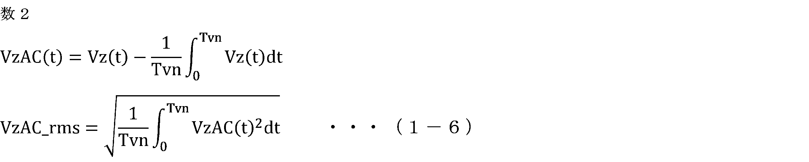
また、零相時間遅れ偏差値Vzdifは、次式に示すように、零相電圧値Vzと、零相電圧値Vzを切換周期Tvのj倍値(jは1以上の自然数)だけ遅らせた時間遅れ零相電圧値との偏差である。ここで、jは、交流回転電機の機械的な共振周期の半周期Tm/2と、切換周期Tvのj倍値との差を最小にする自然数に設定される。
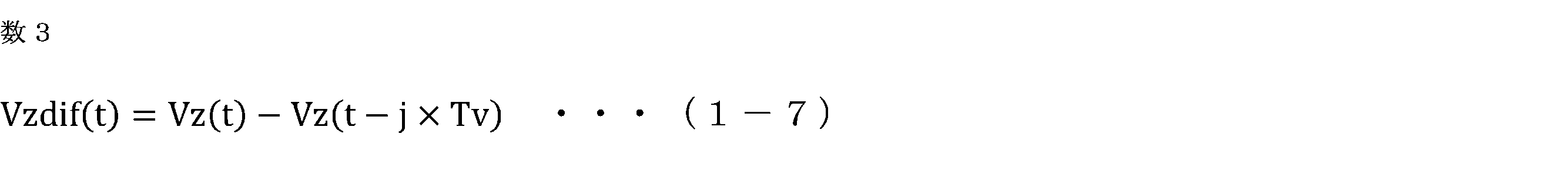
零相時間遅れ偏差値Vzdifの実効値Vzdif_rmsは、次式に示すように、零相時間遅れ偏差値Vzdifの2乗値を、一巡周期Tvnで平均した値の平方根になる。

以上が、考え方Aである。
<n個の零相候補電圧値の設定例>
次に、図9に示したように、交流回転電機1の機械的な共振周期周波数が2500Hz(機械的な共振周期Tm=400us)であり、零相電圧値Vzの切換周期Tv=100μsである場合は、共振周期の半周期Tm/2と、切換周期Tvのj倍値との差を最小にするjは、j=2になる。図10の上段に、図4に示した80個の零相候補電圧値を切換周期Tvで順番に出力された零相電圧値Vz(t)を示す、図10の下段に、式(1-7)に示すように、零相電圧値Vz(t)から、零相電圧値Vz(t)を切換周期Tvのj倍値(本例では、100μs×2=200μs)だけ遅らせた時間遅れ零相電圧値Vz(t-200μs)を減算した零相時間遅れ偏差値Vzdif(t)を示す。
次に、図9に示したように、交流回転電機1の機械的な共振周期周波数が2500Hz(機械的な共振周期Tm=400us)であり、零相電圧値Vzの切換周期Tv=100μsである場合は、共振周期の半周期Tm/2と、切換周期Tvのj倍値との差を最小にするjは、j=2になる。図10の上段に、図4に示した80個の零相候補電圧値を切換周期Tvで順番に出力された零相電圧値Vz(t)を示す、図10の下段に、式(1-7)に示すように、零相電圧値Vz(t)から、零相電圧値Vz(t)を切換周期Tvのj倍値(本例では、100μs×2=200μs)だけ遅らせた時間遅れ零相電圧値Vz(t-200μs)を減算した零相時間遅れ偏差値Vzdif(t)を示す。
式(1-6)を用い、図10の上段の零相電圧値Vz(t)の交流成分の実効値VzAC_rmsを計算すると、VzAC_rms=0.3445Vである。一方、式(1-8)を用い、図10の下段の零相時間遅れ偏差値Vzdif(t)の実効値Vzdif_rmsを計算すると、Vzdif_rms=0.329Vである。よって、式(1-5)のように、VzAC_rms>Vzdif_rmsになるように、80個の零相候補電圧値が設定されており、上記の考え方Aを満たしている。
図11の上段に、図10の上段の零相電圧値Vzの周波数解析結果を示し、図11の下段に、図10の下段の零相時間遅れ偏差値Vzdifの周波数解析結果を示す。考え方Aを満たす場合は、図11に示すように、零相電圧値Vz及び零相時間遅れ偏差値Vzdifに含まれる機械的共振周波数(2500Hz近傍)の成分が小さくなっている。これにより、零相電圧値Vzに含まれる交流回転電機1の機械的な共振周期Tmの成分を低減することができ、交流回転電機1の騒音を低減することができる。
次に、考え方Aを満たさないn個の零相候補電圧値の設定例として、特許文献3(段落0036~0038)に記載された7個の零相候補電圧値(Vzc_1=-0.75V、Vzc_2=-0.5V、Vzc_3=0V、Vzc_4=0.75V、Vzc_5=0.5V、Vzc_6=-0.25V、Vzc_7=0.25V)を用いて説明する。
図12の上段に、特許文献3の7個の零相候補電圧値を用いた場合の零相電圧値Vz(t)を示す、図12の下段に、零相電圧値Vz(t)から、零相電圧値Vz(t)を200μsだけ遅らせた時間遅れ零相電圧値Vz(t-200μs)を減算した零相時間遅れ偏差値Vzdif(t)を示す。図12の上段の特許文献3の零相電圧値Vz(t)の交流成分の実効値VzAC_rmsを計算すると、VzAC_rms=0.500Vである。一方、図12の下段の特許文献3の零相時間遅れ偏差値Vzdif(t)の実効値Vzdif_rms=0.7789Vである。よって、VzAC_rms<Vzdif_rmsであり、上記の考え方Aを満足しない。
図13の上段に、図12の上段の特許文献3の零相電圧値Vzの周波数解析結果を示し、図11の下段に、図12の下段の特許文献3の零相時間遅れ偏差値Vzdifの周波数解析結果を示す。考え方Aを満足しない場合は、図13に示すように、零相電圧値Vz及び零相時間遅れ偏差値Vzdifに含まれる機械的な共振周波数(2500Hz近傍)の成分が大きくなっている。これにより、零相電圧値Vzに含まれる交流回転電機1の機械的な共振周期Tmの成分が大きく、交流回転電機1の騒音が大きくなる。
図14に、図9の感度特性を有する電動パワーステアリング装置用の交流回転電機1における、零相電圧値Vzの設定を変えた場合の騒音レベルの実測結果を示す。図14の左側は、零相電圧値Vz(t)=0の場合であり、図14の中央は、特許文献3の7個の零相候補電圧値による零相電圧値Vz(t)の場合であり、図14の右側は、図4の80個の零相候補電圧値による零相電圧値Vz(t)の場合である。図14の中央の考え方Aを満たしていない特許文献3の場合は、左側の零相電圧値Vz=0の場合よりも騒音が悪化している(特に、機械的共振周波数に近い2.8kHz)。一方、図14の右側の考え方Aを満たす本願の場合は、左側の零相電圧値Vz=0の場合よりも全体的に騒音が低下しており、機械的共振周波数においても、騒音が増加しておらず、低下している。
よって、考え方Aを満たすようにn個の零相候補電圧値を設定し、零相電圧値Vzを3相電圧指令値に加算することで、交流回転電機1の機械的共振周波数帯を含み、多くの周波数帯において、交流回転電機1の騒音を低減することができる。
<n個の零相候補電圧値の第1変形例>
n個の零相候補電圧値の変形例について説明する。n個の零相候補電圧値は、考え方Aを満たすように設定されればよく、図4の80個の零相候補電圧値に限定されない。以下、具体例を述べていく。
n個の零相候補電圧値の変形例について説明する。n個の零相候補電圧値は、考え方Aを満たすように設定されればよく、図4の80個の零相候補電圧値に限定されない。以下、具体例を述べていく。
n=2に設定され、1番目の零相候補電圧値Vzc_1=-0.5V、2番目の零相候補電圧値Vzc_1=0.5Vに設定されている場合について説明する。図15の上段に、2個の零相候補電圧値Vzc_1、Vzc_2が切換周期Tv=100μsで順番に出力された零相電圧値Vz(t)を示す。図16の下段に、考え方Aを満たすようにj=2に設定し、零相電圧値Vz(t)から、零相電圧値Vz(t)を切換周期Tvのj倍値(本例では、100μs×2=200μs)だけ遅らせた時間遅れ零相電圧値Vz(t-200μs)を減算した零相時間遅れ偏差値Vzdif(t)を示す。
図15の上段の零相電圧値Vz(t)の交流成分の実効値VzAC_rms=0.500Vであり、図15の下段の零相時間遅れ偏差値Vzdif(t)の実効値Vzdif_rms=0Vであり、VzAC_rms>Vzdif_rmsになり、考え方Aが満たされている。
図16の上段に、図15の上段の零相電圧値Vzの周波数解析結果を示し、図16の下段に、図15の下段の零相時間遅れ偏差値Vzdifの周波数解析結果を示す。考え方Aを満たす場合は、図16に示すように、零相電圧値Vz及び零相時間遅れ偏差値Vzdifに含まれる機械的共振周波数(2500Hz近傍)の成分が小さくなっている。これにより、零相電圧値Vzに含まれる交流回転電機1の機械的な共振周期Tmの成分を低減することができ、交流回転電機1の騒音を低減することができる。
図17に、2個の零相候補電圧値による零相電圧値Vzを加算した場合の、U相巻線の印加電圧Vu_PWMの周波数解析結果を示す。図17には、図7に示した零相電圧値Vzを加算しない場合の高調波成分のレベルを点線で示している。同図より、零相電圧値Vzの加算により、印加電圧のオンタイミング及びオフタイミングが全相等しく変動するため、150kHz~3000kHzの多くの帯域において、高調波成分が低減しており、インバータ4より生じるノイズを低減することができる。考え方Aを満たしているので、交流回転電機1の機械的共振周波数帯を含み、多くの周波数帯において、交流回転電機1の騒音を低減することができる。
<n個の零相候補電圧値の第2変形例>
図18に、n=10の場合の10個の零相候補電圧値Vzc_1~Vzc_10の設定例を示す。零相電圧値算出部33は、切換周期Tv毎に、1番目の零相候補電圧値Vzc_1から10番目の零相候補電圧値Vzc_10まで順番に選択し、選択した零相候補電圧値Vzcを零相電圧値Vzとして算出する。なお、10番目の零相候補電圧値Vzc_10の次は、1番目の零相候補電圧値Vzc_1が選択される。
図18に、n=10の場合の10個の零相候補電圧値Vzc_1~Vzc_10の設定例を示す。零相電圧値算出部33は、切換周期Tv毎に、1番目の零相候補電圧値Vzc_1から10番目の零相候補電圧値Vzc_10まで順番に選択し、選択した零相候補電圧値Vzcを零相電圧値Vzとして算出する。なお、10番目の零相候補電圧値Vzc_10の次は、1番目の零相候補電圧値Vzc_1が選択される。
図19の上段に、10個の零相候補電圧値Vzc_1~Vzc_10が切換周期Tv=100μsで順番に出力された零相電圧値Vz(t)を示す。図19の下段に、考え方Aを満たすようにj=2に設定し、零相電圧値Vz(t)から、零相電圧値Vz(t)を切換周期Tvのj倍値(本例では、100μs×2=200μs)だけ遅らせた時間遅れ零相電圧値Vz(t-200μs)を減算した零相時間遅れ偏差値Vzdif(t)を示す。
図19の上段の零相電圧値Vz(t)の交流成分の実効値VzAC_rms=5.07Vであり、図19の下段の零相時間遅れ偏差値Vzdif(t)の実効値Vzdif_rms=2.53Vであり、VzAC_rms>Vzdif_rmsになり、考え方Aが満たされている。
図20の上段に、図19の上段の零相電圧値Vzの周波数解析結果を示し、図20の下段に、図19の下段の零相時間遅れ偏差値Vzdifの周波数解析結果を示す。考え方Aを満たす場合は、図20に示すように、零相電圧値Vz及び零相時間遅れ偏差値Vzdifに含まれる機械的共振周波数(2500Hz近傍)の成分が小さくなっている。これにより、零相電圧値Vzに含まれる交流回転電機1の機械的な共振周期Tmの成分を低減することができ、交流回転電機1の騒音を低減することができる。
図21に、10個の零相候補電圧値による零相電圧値Vzを加算した場合の、U相巻線の印加電圧Vu_PWMの周波数解析結果を示す。図21には、図7に示した零相電圧値Vzを加算しない場合の高調波成分のレベルを点線で示している。同図より、零相電圧値Vzの加算により、印加電圧のオンタイミング及びオフタイミングが全相等しく変動するため、150kHz~3000kHzの多くの帯域において、高調波成分が低減しており、インバータ4より生じるノイズを低減することができる。また、考え方Aを満たしているので、交流回転電機1の機械的共振周波数帯を含み、多くの周波数帯において、交流回転電機1の騒音を低減することができる。
<n個の零相候補電圧値の第3変形例>
図22に、n=40の場合の40個の零相候補電圧値Vzc_1~Vzc_40の設定例を示す。零相電圧値算出部33は、切換周期Tv毎に、1番目の零相候補電圧値Vzc_1から40番目の零相候補電圧値Vzc_40まで順番に選択し、選択した零相候補電圧値Vzcを零相電圧値Vzとして算出する。なお、40番目の零相候補電圧値Vzc_40の次は、1番目の零相候補電圧値Vzc_1が選択される。
図22に、n=40の場合の40個の零相候補電圧値Vzc_1~Vzc_40の設定例を示す。零相電圧値算出部33は、切換周期Tv毎に、1番目の零相候補電圧値Vzc_1から40番目の零相候補電圧値Vzc_40まで順番に選択し、選択した零相候補電圧値Vzcを零相電圧値Vzとして算出する。なお、40番目の零相候補電圧値Vzc_40の次は、1番目の零相候補電圧値Vzc_1が選択される。
図23の上段に、40個の零相候補電圧値Vzc_1~Vzc_40が切換周期Tv=100μsで順番に出力された零相電圧値Vz(t)を示す。図23の下段に、考え方Aを満たすようにj=2に設定し、零相電圧値Vz(t)から、零相電圧値Vz(t)を切換周期Tvのj倍値(本例では、100μs×2=200μs)だけ遅らせた時間遅れ零相電圧値Vz(t-200μs)を減算した零相時間遅れ偏差値Vzdif(t)を示す。
図23の上段の零相電圧値Vz(t)の交流成分の実効値VzAC_rms=3.94Vであり、図23の下段の零相時間遅れ偏差値Vzdif(t)の実効値Vzdif_rms=3.18Vであり、VzAC_rms>Vzdif_rmsになり、考え方Aが満たされている。
図24の上段に、図23の上段の零相電圧値Vzの周波数解析結果を示し、図24の下段に、図23の下段の零相時間遅れ偏差値Vzdifの周波数解析結果を示す。考え方Aを満たす場合は、図24に示すように、零相電圧値Vz及び零相時間遅れ偏差値Vzdifに含まれる機械的共振周波数(2500Hz近傍)の成分が小さくなっている。これにより、零相電圧値Vzに含まれる交流回転電機1の機械的な共振周期Tmの成分を低減することができ、交流回転電機1の騒音を低減することができる。
図25に、40個の零相候補電圧値による零相電圧値Vzを加算した場合の、U相巻線の印加電圧Vu_PWMの周波数解析結果を示す。図25には、図7に示した零相電圧値Vzを加算しない場合の高調波成分のレベルを点線で示している。同図より、零相電圧値Vzの加算により、印加電圧のオンタイミング及びオフタイミングが全相等しく変動するため、150kHz~3000kHzの多くの帯域において、高調波成分が低減しており、インバータ4より生じるノイズを低減することができる。また、考え方Aを満たしているので、交流回転電機1の機械的共振周波数帯を含み、多くの周波数帯において、交流回転電機1の騒音を低減することができる。
<まとめ>
以上、複数の具体例について述べた。本願の目的は、インバータ4より生じるノイズ(EMI)を低減することと、交流回転電機1の騒音を小さくすることの両立である。そのために、本願では、考え方Aを満足するように、n個の零相候補電圧値を設定することによって、零相電圧値Vz及び零相時間遅れ偏差値Vzdifに含まれる交流回転電機1の機械的共振周期Tmの成分を小さくでき、交流回転電機1の騒音を低減できる。複数の具体例より、nを大きくするほど、巻線の印加電圧に含まれる150kHz~3000kHzの成分が低減する傾向である。
以上、複数の具体例について述べた。本願の目的は、インバータ4より生じるノイズ(EMI)を低減することと、交流回転電機1の騒音を小さくすることの両立である。そのために、本願では、考え方Aを満足するように、n個の零相候補電圧値を設定することによって、零相電圧値Vz及び零相時間遅れ偏差値Vzdifに含まれる交流回転電機1の機械的共振周期Tmの成分を小さくでき、交流回転電機1の騒音を低減できる。複数の具体例より、nを大きくするほど、巻線の印加電圧に含まれる150kHz~3000kHzの成分が低減する傾向である。
よって、本願を実施する場合、まずは考え方Aを満足するようにn個の零相候補電圧値を決定し、零相電圧値Vzに含まれる交流回転電機1の機械的共振周期Tmの成分を小さくする。そのうえで、巻線の印加電圧に含まれる150kHz~3000kHzの成分が仕様を満足されればよいが、満足しない場合、nを増やして再度仕様を満足するかを確認すればよい。ただし、nは少なくとも2個は必要となる。
<n個の零相候補電圧値の振幅の調整>
また、nを増やすことに加えて、n個の零相候補電圧値の振幅を調整することも有効である。図26に、図18に示した10個の零相候補電圧値をすべて2倍にして用いた場合の、U相巻線の印加電圧Vu_PWMの周波数解析結果を示す。2倍していない図21と比べ、2倍している図26では、おおよそ300kHz~500kHz近傍の高調波成分が低減している。よって、n個の零相候補電圧値の振幅を調整することはノイズレベルの調整に有効である。
また、nを増やすことに加えて、n個の零相候補電圧値の振幅を調整することも有効である。図26に、図18に示した10個の零相候補電圧値をすべて2倍にして用いた場合の、U相巻線の印加電圧Vu_PWMの周波数解析結果を示す。2倍していない図21と比べ、2倍している図26では、おおよそ300kHz~500kHz近傍の高調波成分が低減している。よって、n個の零相候補電圧値の振幅を調整することはノイズレベルの調整に有効である。
おおよその目安として、LW帯(150kHz~500kHz)を十分に低減したい場合は、n個の零相候補電圧値の内の最大値と、n個の零相候補電圧値の内の最小値との差が、インバータに供給される直流電圧Vdcの10%以上になるように、n個の零相候補電圧値が予め設定されればよい。
AM帯(500kHz~1730kHz)を十分に低減したい場合は、n個の零相候補電圧値の内の最大値と、n個の零相候補電圧値の内の最小値との差が、インバータに供給される直流電圧Vdcの5%以上になるように、n個の零相候補電圧値が予め設定されればよい。
<各周期の設定>
本願に係る電動パワーステアリング装置用の交流回転電機1の機械的な共振周期Tmは、200μs以上、500μs以下の範囲内である(機械的共振周波数は、2kHz以上、5kHz以下)。より好ましくは、機械的な共振周期Tmは、300μs以上、400μs以下の範囲内である(機械的共振周波数は、2.5kHz以上、3.3kHz以下)。また、PWM周期Tcが、60μs以下、6.67μs以上である場合に、ノイズを低減し、且つ交流回転電機1の騒音を低減する電動パワーステアリング装置100に用いると好適である。PWM周期Tcが、60μs以下、6.67μs以上であると、PWM周波数(1/Tc)が、16kHz以上、150kHz以下になり、150kHz以上では、ノイズ低減効果が低下し、16kHz未満では、交流回転電機1のPWM周波数の成分の音が目立つため人間の可聴域の騒音が悪化する。
本願に係る電動パワーステアリング装置用の交流回転電機1の機械的な共振周期Tmは、200μs以上、500μs以下の範囲内である(機械的共振周波数は、2kHz以上、5kHz以下)。より好ましくは、機械的な共振周期Tmは、300μs以上、400μs以下の範囲内である(機械的共振周波数は、2.5kHz以上、3.3kHz以下)。また、PWM周期Tcが、60μs以下、6.67μs以上である場合に、ノイズを低減し、且つ交流回転電機1の騒音を低減する電動パワーステアリング装置100に用いると好適である。PWM周期Tcが、60μs以下、6.67μs以上であると、PWM周波数(1/Tc)が、16kHz以上、150kHz以下になり、150kHz以上では、ノイズ低減効果が低下し、16kHz未満では、交流回転電機1のPWM周波数の成分の音が目立つため人間の可聴域の騒音が悪化する。
2.実施の形態2
実施の形態2に係る交流回転電機1、インバータ4、及び制御装置10について説明する。上記の実施の形態1と同様の構成部分は説明を省略する。本実施の形態に係る交流回転電機1、インバータ4、及び制御装置10の基本的な構成は実施の形態1と同様であるが、インバータ4に電流センサが設けられており、制御装置10が電流検出に基づいて、電圧指令値を設定する点が実施の形態1と異なる。図27は、本実施の形態に係る交流回転電機1、インバータ4、及び制御装置10の概略構成図である。
実施の形態2に係る交流回転電機1、インバータ4、及び制御装置10について説明する。上記の実施の形態1と同様の構成部分は説明を省略する。本実施の形態に係る交流回転電機1、インバータ4、及び制御装置10の基本的な構成は実施の形態1と同様であるが、インバータ4に電流センサが設けられており、制御装置10が電流検出に基づいて、電圧指令値を設定する点が実施の形態1と異なる。図27は、本実施の形態に係る交流回転電機1、インバータ4、及び制御装置10の概略構成図である。
インバータ4の3相の直列回路は、各相の負極側のスイッチング素子SNに直列接続されたU相の抵抗Ru、V相の抵抗Rv、W相の抵抗Rwを有する。各相の抵抗Ru、Rv、Rwは、負極側のスイッチング素子SNの負極側に直列接続されている。本実施の形態では、3相の抵抗Ru、Rv、Rwは、電流検出用のシャント抵抗とされており、アンプ21、22、23により各相の抵抗の両端電位差が検出され、両端電位差が制御装置10に入力される。よって、本実施の形態のインバータ4は、いわゆる、下アーム3シャント方式のインバータとなっている。
なお、各相の抵抗は、正極側のスイッチング素子SPに直列接続されてもよい。或いは、インバータ4と直流電源3とを接続する正極側の母線又は負極側の母線に、抵抗が直列接続されてもよい。
本実施の形態では、電圧指令算出部32は、各相の抵抗Ru、Rv、Rwの両端電位差に基づいて、各相の巻線に流れる電流Iud、Ivd、Iwdを検出する。そして、電圧指令算出部32は、次式に示すように、3相の電流検出値Iud、Ivd、Iwdを、磁極位置θに基づいて3相2相変換及び回転座標変換を行って、d軸の電流検出値Idd及びq軸の電流検出値Iqdに変換する。

なお、インバータ4と直流電源3とを接続する正極側の母線又は負極側の母線に、抵抗が直列接続される場合は、電圧指令算出部32は、抵抗の両端電位差に基づいて、母線電流を検出し、公知の方法を用い、母線電流を検出した時点の各相のスイッチング素子のオンオフパターン、及び母線電流に基づいて、各相の巻線電流Iud、Ivd、Iwdを検出する。
実施の形態1と同様に、電圧指令算出部32は、トルクセンサ106の出力信号に基づいて、運転者の操舵トルクTsを検出する。電圧指令算出部32は、式(1-1)に示したように、操舵トルクTsに基づいてq軸の電流指令値Iqoを設定し、d軸の電流指令値Idoを0に設定する。
そして、電圧指令算出部32は、d軸及びq軸の電流検出値Idd、Iqdが、d軸及びq軸の電流指令値Ido、Iqoに近づくように、3相の電圧指令値Vub、Vvb、Vwbを変化させる。電圧指令算出部32は、次式に示すように、d軸の電流検出値Iddがd軸の電流指令値Idoに近づくように、PI制御によりd軸の電圧指令値Vdoを変化させ、q軸の電流検出値Iqdがq軸の電流指令値Iqoに近づくように、PI制御によりq軸の電圧指令値Vqoを変化させる。なお、d軸電流とq軸電流の非干渉化のため等のフィードフォワード制御が行われてもよい。

ここで、Kd、Kqは、比例ゲインであり、Td、Tqは、積分時定数であり、sは、ラプラス演算子である。
そして、実施の形態1と同様に、電圧指令算出部32は、式(1-3)に示したように、d軸及びq軸の電圧指令値Vdo、Vqoを、磁極位置θに基づいて、固定座標変換及び2相3相変換を行って、3相の電圧指令値Vub、Vvb、Vwbに変換する。
実施の形態1と同様に、零相電圧値算出部33は、値が異なるn個(nは2以上の自然数)の零相候補電圧値Vzc_1~Vzc_nを、切換周期Tv毎に順番に切り替えて零相電圧値Vzとして算出する。n個の零相候補電圧値Vzc_1~Vzc_nは、考え方Aを満たすように予め設定されている。
実施の形態1と同様に、電圧指令補正部34は、零相電圧値Vzに基づいて、3相の電圧指令値Vub、Vvb、Vwbを補正する。電圧指令補正部34は、式(1-4)に示したように、3相の電圧指令値Vub、Vvb、Vwbのそれぞれに、零相電圧値Vzを加算して、補正後の3相の電圧指令値Vuc、Vvc、Vwcを算出する。
実施の形態1と同様に、PWM制御部35は、補正後の3相の電圧指令値Vuc、Vvc、Vwcに基づいて、インバータ4の複数のスイッチング素子をオンオフ制御する。
<電流検出タイミング>
抵抗の両端電位差に基づく電流検出タイミングについて説明する。U相の直列回路においては、負極側のスイッチング素子SNuがオンである場合に、U相の抵抗Ruに電流が流れ、抵抗を流れる電流は、U相の巻線Cuに流れる電流Iuに等しくなる。よって、U相の巻線電流Iuの検出は、U相の負極側のスイッチング素子SNuがオンであれば、任意のタイミングで行うことができる。同様に、V相の巻線電流Ivの検出は、V相の負極側のスイッチング素子SNvがオンであれば、任意のタイミングで行うことができる。W相の巻線電流Iwの検出は、W相の負極側のスイッチング素子SNwがオンであれば、任意のタイミングで行うことができる。
抵抗の両端電位差に基づく電流検出タイミングについて説明する。U相の直列回路においては、負極側のスイッチング素子SNuがオンである場合に、U相の抵抗Ruに電流が流れ、抵抗を流れる電流は、U相の巻線Cuに流れる電流Iuに等しくなる。よって、U相の巻線電流Iuの検出は、U相の負極側のスイッチング素子SNuがオンであれば、任意のタイミングで行うことができる。同様に、V相の巻線電流Ivの検出は、V相の負極側のスイッチング素子SNvがオンであれば、任意のタイミングで行うことができる。W相の巻線電流Iwの検出は、W相の負極側のスイッチング素子SNwがオンであれば、任意のタイミングで行うことができる。
しかし、本実施の形態では、図28に示すように、電圧指令算出部32は、キャリア波の山の頂点のタイミングで、各相の抵抗Ru、Rv、Rwの両端電位差に基づいて、各相の巻線に流れる電流Iud、Ivd、Iwdを検出する。なお、各相の抵抗Ru、Rv、Rwが、正極側のスイッチング素子に直列接続される場合は、電圧指令算出部32は、キャリア波の谷の頂点のタイミングで、各相の抵抗Ru、Rv、Rwの両端電位差に基づいて、各相の巻線に流れる電流Iud、Ivd、Iwdを検出するように構成される。
以下、その影響について説明する。図28は、PWM周期Tcの3周期分の制御挙動を示している。実施の形態1と同様に、零相電圧値Vzの切換周期Tvは、PWM周期Tcと同じに設定されており、キャリア波CAの谷の頂点のタイミングで、零相電圧値Vzが切り替えられている。図28では、1番目の零相候補電圧値Vzc_1、2番目の零相候補電圧値Vzc_2、及び3番目の零相候補電圧値Vzc_3が、切換周期Tv毎に順番に零相電圧値Vzに設定されている。3相の電圧指令値Vub、Vvb、Vwbは異なる値に設定されている。そのため、零相電圧値Vzの加算後の3相の電圧指令値Vuc、Vvc、Vwcは、異なる値になっており、切換周期Tv毎に零相電圧値Vzの変化に応じて変化している。
図28には、U相の巻線に流れる電流Iu、V相の巻線に流れる電流Iv、W相の巻線に流れる電流Iwを示している。また、各相の電流Iu、Iv、IwのPWM周期Tc間の移動平均値Iu_ave、Iv_ave、Iw_aveを示している。各相の巻線電流Iu、Iv、Iwは、各相の巻線電流の平均値Iu_ave、Iv_ave、Iw_aveに対してリップル成分を含んでいる。しかし、キャリア波CAの山の頂点(又は谷の頂点)では、各相の巻線電流Iu、Iv、Iwは、各相の巻線電流の平均値Iu_ave、Iv_ave、Iw_aveに一致する。よって、電流検出タイミングを、キャリア波CAの山の頂点に設定することで、リップル成分を含む巻線電流から、回転周期の基本波成分を検出することができる。
特に、電動パワーステアリング装置用の交流回転電機1の制御では、巻線電流を高精度に検出することが求められる。巻線電流の検出値に巻線電流の真値に対する誤差が生じると、真値に対し誤差をもつ巻線電流の検出値を電流指令値に一致させるように制御され、交流回転電機1の出力トルクにトルクリップルが生じる。トルクリップルがシャフト105を介して、ハンドル104に伝達され、運転者の操舵感を悪化させる。
電流検出タイミングを、キャリア波CAの山の頂点に設定することにより、リップル成分を含む巻線電流からその基本波を検出することができる。よって、巻線電流を高精度に検出することができ、電流検出誤差によるトルクリップルの発生を抑制し、運転者の良好なハンドルの操舵感が得られる。
次に、負極側のスイッチング素子SNに抵抗Rを直列接続し、考え方Aによりn個の零相候補電圧値を設定することの利点について説明する。
<抵抗Rを設けない場合の、巻線電流への影響>
図29に、抵抗Rを設けない場合の、インバータ4の1相分の直列回路の等価回路を示す。正極側のスイッチング素子SP及び負極側のスイッチング素子SNをスイッチで表し、導通抵抗は無視する。正極側のスイッチング素子SP及び負極側のスイッチング素子SNの中間に、対応する相の巻線に接続される出力端子があり、出力端子の電位Voutは、巻線の印加電圧になる。
図29に、抵抗Rを設けない場合の、インバータ4の1相分の直列回路の等価回路を示す。正極側のスイッチング素子SP及び負極側のスイッチング素子SNをスイッチで表し、導通抵抗は無視する。正極側のスイッチング素子SP及び負極側のスイッチング素子SNの中間に、対応する相の巻線に接続される出力端子があり、出力端子の電位Voutは、巻線の印加電圧になる。
ここで、PWM周期Tcにおける正極側のスイッチング素子SPのオン期間の割合をDとすると、PWM周期Tcにおける出力端子の電位Voutの平均値Vout_aveは、次式で表せる。
Vout_ave=D×Vdc ・・・(2-3)
Vout_ave=D×Vdc ・・・(2-3)
同様に、U相の直列回路の出力端子電位の平均値Voutu_ave、及びV相の直列回路の出力端子電位の平均値Voutv_aveは、U相の正極側のスイッチング素子SPuのオン期間の割合をDuとし、V相の正極側のスイッチング素子SPvのオン期間の割合をDvとすると、次式で表せる。
Voutu_ave=Du×Vdc
Voutv_ave=Dv×Vdc ・・・(2-4)
Voutu_ave=Du×Vdc
Voutv_ave=Dv×Vdc ・・・(2-4)
ここで、式(2-4)の状態に零相電圧値Vzを加算した場合に、零相電圧値Vzを加算による各相のオン期間の割合の変動分をΔDとすると、次式で表せる。
Voutu_ave=(Du+ΔD)×Vdc
Voutv_ave=(Dv+ΔD)×Vdc ・・・(2-5)
Voutu_ave=(Du+ΔD)×Vdc
Voutv_ave=(Dv+ΔD)×Vdc ・・・(2-5)
式(2-5)から、U相とV相間の線間電圧ΔVout_uvは、次式で表せる。
ΔVout_uv=Voutu_ave-Voutv_ave
=(Du-Dv)×Vdc ・・・(2-6)
ΔVout_uv=Voutu_ave-Voutv_ave
=(Du-Dv)×Vdc ・・・(2-6)
この式からわかるように、線間電圧に、零相電圧値Vzの加算による影響は生じない。抵抗Rを設けない場合は、交流回転電機1の巻線電流は線間電圧に基づいて流れるので、零相電圧値Vzの影響は巻線電流には表れない。
<抵抗Rを設けた場合の、巻線電流への影響>
図30に、抵抗Rを設けた場合の、インバータ4の1相分の直列回路の等価回路を示す。図29に加えて、負極側のスイッチング素子SNの負極側に抵抗Rが直列接続されている。正極側のスイッチング素子SP及び負極側のスイッチング素子SNの中間に、対応する相の巻線に接続される出力端子があり、出力端子の電位Voutは、巻線の印加電圧になる。
図30に、抵抗Rを設けた場合の、インバータ4の1相分の直列回路の等価回路を示す。図29に加えて、負極側のスイッチング素子SNの負極側に抵抗Rが直列接続されている。正極側のスイッチング素子SP及び負極側のスイッチング素子SNの中間に、対応する相の巻線に接続される出力端子があり、出力端子の電位Voutは、巻線の印加電圧になる。
抵抗Rを巻線電流Iが流れることによって電圧降下が生じ、PWM周期Tcにおける出力端子の電位Voutの平均値Vout_aveは、次式で表せる。ここで、抵抗Rの抵抗値をRで表している。
Vout_ave=D×Vdc+(1-D)×(-R×I)
・・・(2-7)
Vout_ave=D×Vdc+(1-D)×(-R×I)
・・・(2-7)
同様に、U相の直列回路の出力端子電位の平均値Voutu_ave、及びV相の直列回路の出力端子電位の平均値Voutv_aveは、U相の正極側のスイッチング素子SPuのオン期間の割合をDuとし、V相の正極側のスイッチング素子SPvのオン期間の割合をDvとし、U相の巻線電流をIuとし、V相の巻線電流をIvとすると、次式で表せる。
Voutu_ave=Du×Vdc+(1-Du)×(-R×Iu)
Voutv_ave=Dv×Vdc+(1-Dv)×(-R×Iv)
・・・(2-8)
Voutu_ave=Du×Vdc+(1-Du)×(-R×Iu)
Voutv_ave=Dv×Vdc+(1-Dv)×(-R×Iv)
・・・(2-8)
ここで、式(2-8)の状態に零相電圧値Vzを加算した場合に、零相電圧値Vzを加算による各相のオン期間の割合の変動分をΔDとすると、次式で表せる。
Voutu_ave=(Du+ΔD)×Vdc+(1-(Du+ΔD))×(-R×Iu)
Voutv_ave=(Dv+ΔD)×Vdc+(1-(Dv+ΔD))×(-R×Iv)
・・・(2-9)
Voutu_ave=(Du+ΔD)×Vdc+(1-(Du+ΔD))×(-R×Iu)
Voutv_ave=(Dv+ΔD)×Vdc+(1-(Dv+ΔD))×(-R×Iv)
・・・(2-9)
式(2-9)から、U相とV相間の線間電圧ΔVout_uvは、次式で表せる。
ΔVout_uv=Voutu_ave-Voutv_ave
=(Du-Dv)×Vdc+ΔD×R×(Iu-Iv)
・・・(2-10)
ΔVout_uv=Voutu_ave-Voutv_ave
=(Du-Dv)×Vdc+ΔD×R×(Iu-Iv)
・・・(2-10)
抵抗Rを設けない場合の式(2-6)と比べて、抵抗Rを設ける場合の式(2-10)では、右辺の第2項に「ΔD×R×(Iu-Iv)」が追加されている。よって、抵抗Rを設けた場合は、線間電圧に、零相電圧値Vzを加算の影響が生じ、零相電圧値Vzの影響が巻線電流に表れる。
よって、本実施の形態のような下アーム3シャント方式のインバータ、或いは、上アーム3シャント方式のインバータ、母線1シャント方式のインバータのように、負極側のスイッチング素子SNがオンした場合の抵抗と正極側のスイッチング素子SPがオンした場合の抵抗とが異なるインバータにおいては、零相電圧値Vzの加算の影響が、線間電圧及び巻線電流に表れてしまう。
<考え方Aによる騒音の低減>
以下で、インバータ4に抵抗Rを設けることによって、零相電圧値Vzの加算により巻線電流の変動が増加する場合でも、考え方Aを満たす零相電圧値Vzの加算により、交流回転電機1の騒音が低減することを示す。
以下で、インバータ4に抵抗Rを設けることによって、零相電圧値Vzの加算により巻線電流の変動が増加する場合でも、考え方Aを満たす零相電圧値Vzの加算により、交流回転電機1の騒音が低減することを示す。
図31及び図32に、本実施の形態に係る下アーム3シャント方式のインバータにおいて、図9の感度特性を有する電動パワーステアリング装置用の交流回転電機1における、零相電圧値Vzの設定を変えた場合の騒音レベルの実測結果を示す。図31は、巻線電流の実効値=10Armsの場合であり、図32は、巻線電流の実効値=70Armsの場合である。
図31及び図32の左側は、零相電圧値Vz(t)=0の場合であり、図31及び図32の中央は、特許文献3の7個の零相候補電圧値による零相電圧値Vz(t)の場合であり、図31及び図32の右側は、図4の80個の零相候補電圧値による零相電圧値Vz(t)の場合である。図31及び図32の中央の考え方Aを満たさない特許文献3の場合は、左側の零相電圧値Vz=0の場合よりも騒音が悪化しており(特に、機械的共振周波数に近い2.8kHz)、巻線電流の実効値が小さい図31よりも巻線電流の実効値が大きい図32の方が、騒音の悪化度合いが大きくなっている。
一方、図31及び図32の右側の考え方Aを満たす本願の場合は、左側の零相電圧値Vz=0の場合よりも全体的に騒音が低下しており、機械的共振周波数においても、騒音が増加しておらず、低下している。よって、インバータ4への抵抗Rの設置及び零相電圧値Vzの加算による騒音の増加よりも、考え方Aを満たす零相電圧値Vzの加算による騒音の低下の方が上回っている。すなわち、下アーム3シャント方式、上アーム3シャント方式、及び母線1シャント方式のインバータのように、インバータ4に抵抗Rを設ける場合でも、考え方Aを満たすようにn個の零相候補電圧値を設定し、零相電圧値Vzを3相電圧指令値に加算することで、交流回転電機1の機械的共振周波数帯を含み、多くの周波数帯において、交流回転電機1の騒音を低減することができる。
3.実施の形態3
実施の形態3に係る交流回転電機1、インバータ4、及び制御装置10について説明する。上記の実施の形態1と同様の構成部分は説明を省略する。本実施の形態に係る交流回転電機1、インバータ4、及び制御装置10の基本的な構成は実施の形態1、2と同様であるが、制御装置10が指令電圧ベクトルを設定し、零相電圧値Vzに基づいて指令電圧ベクトルを補正し、補正後の指令電圧ベクトルに基づいてスイッチング素子のオンオフ制御を行う点が実施の形態1、2と異なる。
実施の形態3に係る交流回転電機1、インバータ4、及び制御装置10について説明する。上記の実施の形態1と同様の構成部分は説明を省略する。本実施の形態に係る交流回転電機1、インバータ4、及び制御装置10の基本的な構成は実施の形態1、2と同様であるが、制御装置10が指令電圧ベクトルを設定し、零相電圧値Vzに基づいて指令電圧ベクトルを補正し、補正後の指令電圧ベクトルに基づいてスイッチング素子のオンオフ制御を行う点が実施の形態1、2と異なる。
<電圧指令算出部32>
本実施の形態では、電圧指令算出部32は、3相の巻線に印加する電圧を、3相の巻線に関連付けた2軸の固定座標系で表した指令電圧ベクトルVoを算出する。本実施の形態では、図33に示すように、2軸の固定座標系は、U相の巻線Cuの方向に定めたα軸と、α軸より電気角で90°進んだ方向に定めたβ軸とからなる。磁極位置θは、α軸に対するd軸の角度である。
本実施の形態では、電圧指令算出部32は、3相の巻線に印加する電圧を、3相の巻線に関連付けた2軸の固定座標系で表した指令電圧ベクトルVoを算出する。本実施の形態では、図33に示すように、2軸の固定座標系は、U相の巻線Cuの方向に定めたα軸と、α軸より電気角で90°進んだ方向に定めたβ軸とからなる。磁極位置θは、α軸に対するd軸の角度である。
電圧指令算出部32は、実施の形態1又は2と同様の方法を用いて、d軸の電圧指令値Vdo及びq軸の電圧指令値Vqoを算出する。
本実施の形態では、電圧指令算出部32は、次式に示すように、d軸の電圧指令値Vdo及びq軸の電圧指令値Vqoを、磁極位置θに基づいて固定座標変換を行って、α軸の電圧指令値Vα及びβ軸の電圧指令値Vβに変換する。このα軸の電圧指令値Vα及びβ軸の電圧指令値Vβで表される電圧ベクトルが、指令電圧ベクトルVoになる。

電圧指令算出部32は、指令電圧ベクトルVoに基づいて、PWM周期Tcの間に設定する、複数のスイッチング素子の4つのオンオフパターンを決定する共に、PWM周期Tcにおける4つのオンオフパターンの期間を決定する。決定される4つのオンオフパターンには、零電圧ベクトルに対応する2つのオンオフパターンが含まれる。この処理は、公知の空間ベクトルPWMと同様である。
図34に示すように、設定可能なインバータ4の複数のスイッチング素子のオンオフパターンは、全部で8つになる。ここで、「1」は、スイッチング素子がオンされることを示し、「0」は、スイッチング素子がオフされることを示す。8つのオンオフパターンは、図33に示す、8つの基本電圧ベクトルV0~V7に対応する。
第0基本電圧ベクトルV0は、零電圧ベクトルである。すなわち、第0基本電圧ベクトルV0では、3相の正極側のスイッチング素子SPu、SPv、SPwが全てオフになり、3相の負極側のスイッチング素子SNu、SNv、SNwが全てオンになるため、3相の巻線には直流電圧Vdcが印加されない。第7基本電圧ベクトルV7は、零電圧ベクトルである。すなわち、第7基本電圧ベクトルV7では、3相の正極側のスイッチング素子SPu、SPv、SPwが全てオンになり、3相の負極側のスイッチング素子SNu、SNv、SNwが全てオフになるため、3相の巻線には直流電圧Vdcが印加されない。
第1基本電圧ベクトルV1は、U相の巻線の方向のベクトルとなり、第2基本電圧ベクトルV2は、W相の巻線の方向とは逆方向のベクトルとなり、第3基本電圧ベクトルV3は、V相の巻線の方向のベクトルとなり、第4基本電圧ベクトルV4は、U相の巻線の方向とは逆方向のベクトルとなり、第5基本電圧ベクトルV5は、W相の巻線の方向のベクトルとなり、第6基本電圧ベクトルV6は、V相の巻線の方向とは逆方向のベクトルとなる。
電圧指令算出部32は、零電圧ベクトルである第0及び第7基本電圧ベクトルV0、V7を除く6つの基本電圧ベクトルV1~V6から、指令電圧ベクトルVoに近い2つの基本電圧ベクトル(以下、近接基本電圧ベクトルVn1、Vn2と称す)を決定する。そして、電圧指令算出部32は、決定した2つの近接基本電圧ベクトルVn1、Vn2と、第0及び第7基本電圧ベクトルV0、V7を、PWM周期Tcの間に設定する4つの基本電圧ベクトル(以下、設定基本電圧ベクトルと称す)として決定する。
図33の例では、指令電圧ベクトルVoに近い第1基本電圧ベクトルV1と第2基本電圧ベクトルV2が、2つの近接基本電圧ベクトルVn1、Vn2に決定される。
そして、電圧指令算出部32は、指令電圧ベクトルVoを、2つの近接基本電圧ベクトルVn1、Vn2の成分Vn1c、Vn2cに分解する。そして、電圧指令算出部32は、次式に示すように、直流電圧Vdcに対する、2つの近接基本電圧ベクトルの成分Vn1c、Vn2cのそれぞれの大きさに基づいて、PWM周期Tcにおける2つの近接基本電圧ベクトルVn1、Vn2のそれぞれの設定期間の比率Dn1、Dn2を算出する。

図33の例では、2つの近接基本電圧ベクトルの成分Vn1c、Vn2cのそれぞれの大きさは、α軸の電圧指令値Vα及びβ軸の電圧指令値Vβに基づいて、次式にように算出される。
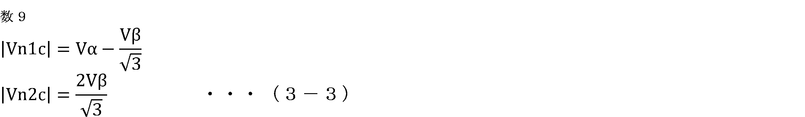
そして、電圧指令算出部32は、PWM周期Tcにおける零電圧ベクトルである第0及び第7基本電圧ベクトルV0、V7のそれぞれの設定期間の比率D0、D7が、次式を満たすように設定する。
D0+D7=1-(Dn1+Dn2) ・・・(3-4)
D0+D7=1-(Dn1+Dn2) ・・・(3-4)
すなわち、PWM周期Tcにおける、2つの近接基本電圧ベクトルVn1、Vn2の設定期間以外の期間は、零電圧ベクトルであるV0、V7に任意には配分して設定することができる。例えば、V0、V7の設定期間の比率D0、D7は、次式のように均等に設定される。
D0=D7={1-(Dn1+Dn2)}/2 ・・・(3-5)
D0=D7={1-(Dn1+Dn2)}/2 ・・・(3-5)
なお、4つの設定基本電圧ベクトルの設定期間の比率Dn1、Dn2、D0、D7のそれぞれにPWM周期Tcを乗算した期間が、4つの設定基本電圧ベクトルの設定期間になる。
<零相電圧値算出部33>
実施の形態1と同様に、零相電圧値算出部33は、値が異なるn個(nは2以上の自然数)の零相候補電圧値Vzc_1~Vzc_nを、切換周期Tv毎に順番に切り替えて零相電圧値Vzとして算出する。n個の零相候補電圧値Vzc_1~Vzc_nは、考え方Aを満たすように予め設定されている。
実施の形態1と同様に、零相電圧値算出部33は、値が異なるn個(nは2以上の自然数)の零相候補電圧値Vzc_1~Vzc_nを、切換周期Tv毎に順番に切り替えて零相電圧値Vzとして算出する。n個の零相候補電圧値Vzc_1~Vzc_nは、考え方Aを満たすように予め設定されている。
<電圧指令補正部34>
本実施の形態では、電圧指令補正部34は、零相電圧値Vzに基づいて、指令電圧ベクトルVoを補正する。電圧指令補正部34は、零相電圧値Vzに応じて、零電圧ベクトルに対応する2つのオンオフパターンの期間(本例では、第0及び第7基本電圧ベクトルV0、V7の設定期間)を、2つの合計期間が変化しないように変化させる。
本実施の形態では、電圧指令補正部34は、零相電圧値Vzに基づいて、指令電圧ベクトルVoを補正する。電圧指令補正部34は、零相電圧値Vzに応じて、零電圧ベクトルに対応する2つのオンオフパターンの期間(本例では、第0及び第7基本電圧ベクトルV0、V7の設定期間)を、2つの合計期間が変化しないように変化させる。
電圧指令補正部34は、次式に示すように、零相電圧値Vzを直流電圧Vdcで除算して、零相電圧補正期間比率Dzを算出する。
Dz=Vz/Vdc ・・・(3-6)
Dz=Vz/Vdc ・・・(3-6)
そして、電圧指令補正部34は、次式に示すように、第0基本電圧ベクトルV0の設定期間の比率D0に零相電圧補正期間比率Dzを加算し、補正後の第0基本電圧ベクトルV0の設定期間の比率D0cを算出し、第7基本電圧ベクトルV7の設定期間の比率D7から零相電圧補正期間比率Dzを減算し、補正後の第7基本電圧ベクトルV7の設定期間の比率D7cを算出する。
D0c=D0+Dz
D7c=D7-Dz ・・・(3-7)
D0c=D0+Dz
D7c=D7-Dz ・・・(3-7)
なお、補正後の第0及び第7基本電圧ベクトルの設定期間の比率D0c、D7cのそれぞれにPWM周期Tcを乗算した期間が、第0及び第7基本電圧ベクトルの設定期間になる。零相電圧値Vzにより、2つの近接基本電圧ベクトルVn1、Vn2の設定期間の比率Dn1、Dn2は変化されない。
<PWM制御部35>
PWM制御部35は、電圧指令算出部32により決定された4つのオンオフパターン(本例では、2つの近接基本電圧ベクトルVn1、Vn2、及び第0及び第7基本電圧ベクトルV0、V7)、及び電圧指令算出部32及び電圧指令補正部34により決定され補正された4つのオンオフパターンの期間(本例では、Dn1、Dn2、D0c、D7c)に基づいて、複数のスイッチング素子をオンオフ制御する。
PWM制御部35は、電圧指令算出部32により決定された4つのオンオフパターン(本例では、2つの近接基本電圧ベクトルVn1、Vn2、及び第0及び第7基本電圧ベクトルV0、V7)、及び電圧指令算出部32及び電圧指令補正部34により決定され補正された4つのオンオフパターンの期間(本例では、Dn1、Dn2、D0c、D7c)に基づいて、複数のスイッチング素子をオンオフ制御する。
PWM制御部35は、PWM周期Tcにおいて設定する4つの設定基本電圧ベクトル(Vn1、Vn2、V0、V7)及びPWM周期Tcにおける4つの設定基本電圧ベクトルの設定期間の比率(Dn1、Dn2、D0c、D7c)に基づいて、各スイッチング素子のスイッチング信号GPu~GNwを生成する。例えば、図33の例では、図35に示すように、各スイッチング素子のスイッチング信号GPu~GNwが生成される。
ここで、各相の正極側のスイッチング素子のスイッチング信号GPu、GPv、GPwに直流電圧Vdcを乗算した電圧は、各相の巻線の印加電圧Vu_PWM、Vv_PWM、Vw_PWMに相当する。
このように、零相電圧値Vzにより、零電圧ベクトルである第0及び第7基本電圧ベクトルの設定期間のみが変化され、零電圧ベクトルでない2つの近接基本電圧ベクトルVn1、Vn2の設定期間は変化されないので、PWM周期Tcにおける巻線への印加電圧の平均値は変化しない。よって、零相電圧値Vzの補正により、PWM周期Tcにおける線間電圧の平均値は変化しないため、巻線電流は変化しない。一方、零相電圧値Vzにより、零電圧ベクトルである第0及び第7基本電圧ベクトルの設定期間を変化させたことにより、各相の巻線の印加電圧Vu_PWM、Vv_PWM、Vw_PWMのオンタイミング及びオフタイミングが全相等しく変動する。そのため、実施の形態1及び2と同様に、150kHz~3000kHzの多くの帯域において、各相の巻線の印加電圧の高調波成分が低減することができ、インバータ4より生じるノイズを低減することができる。また、零相電圧値Vzは考え方Aを満たしているので、交流回転電機1の機械的共振周波数帯を含み、多くの周波数帯において、交流回転電機1の騒音を低減することができる。
〔その他の実施の形態〕
最後に、本願のその他の実施の形態について説明する。なお、以下に説明する各実施の形態の構成は、それぞれ単独で適用されるものに限られず、矛盾が生じない限り、他の実施の形態の構成と組み合わせて適用することも可能である。
最後に、本願のその他の実施の形態について説明する。なお、以下に説明する各実施の形態の構成は、それぞれ単独で適用されるものに限られず、矛盾が生じない限り、他の実施の形態の構成と組み合わせて適用することも可能である。
(1)零相電圧値算出部33は、3相巻線への印加電圧の振幅に応じて、零相電圧値Vzの大きさを変化させてもよい。例えば、実施の形態1、2では、3相巻線への印加電圧の振幅は、3相の電圧指令値Vub、Vvb、Vwbの基本波成分の振幅に設定される。実施の形態3では、3相巻線への印加電圧の振幅は、指令電圧ベクトルVoの大きさに設定される。そして、零相電圧値算出部33は、3相巻線への印加電圧の振幅に応じてゲインを設定し、n個の零相候補電圧値Vzc_1~Vzc_nを切換周期Tv毎に順番に切り替えて設定した電圧値に対して、ゲインを乗算して、零相電圧値Vzを設定する。例えば、零相電圧値算出部33は、3相巻線への印加電圧の振幅が増加するに従って、ゲインを減少させる。また、零相電圧値算出部33は、交流回転電機1の回転速度が増加するに従って、ゲインを減少させる。
(2)零相電圧値算出部33は、直流電圧Vdcに応じて、零相電圧値Vzの大きさを変化させてもよい。零相電圧値算出部33は、直流電圧Vdcに応じてゲインを設定し、n個の零相候補電圧値Vzc_1~Vzc_nを切換周期Tv毎に順番に切り替えて設定した電圧値に対して、ゲインを乗算して、零相電圧値Vzを設定する。例えば、零相電圧値算出部33は、直流電圧Vdcが増加するに従って、ゲインを増加させる。
(3)交流回転電機1は、3相の巻線が設けられた回転電機であればよく、例えば、ロータに電磁石が設けられている界磁巻線型の同期回転機、又はロータに永久磁石が設けられていない誘導機であってもよい。また、交流回転電機1は、3相の巻線が複数組設けられた回転電機であってもよい。各組の3相の巻線に対して、本願の構成が適用できる。
(4)実施の形態2において、インバータ4と3相の巻線とを接続する電線上に、電流センサが設けられてもよい。
(5)交流回転電機1は、電動パワーステアリング装置100以外の各種の装置の駆動力源とされてもよい。例えば、交流回転電機1は、車輪の駆動力源とされてもよい。
本願は、様々な例示的な実施の形態及び実施例が記載されているが、1つ、または複数の実施の形態に記載された様々な特徴、態様、及び機能は特定の実施の形態の適用に限られるのではなく、単独で、または様々な組み合わせで実施の形態に適用可能である。従って、例示されていない無数の変形例が、本願明細書に開示される技術の範囲内において想定される。例えば、少なくとも1つの構成要素を変形する場合、追加する場合または省略する場合、さらには、少なくとも1つの構成要素を抽出し、他の実施の形態の構成要素と組み合わせる場合が含まれるものとする。
1 交流回転電機、4 インバータ、10 交流回転電機の制御装置、32 電圧指令算出部、33 零相電圧値算出部、34 電圧指令補正部、35 PWM制御部、100 電動パワーステアリング装置、CA キャリア波、R 抵抗、Tc PWM周期、Tm 共振周期、Tv 切換周期、Vo 指令電圧ベクトル、Vz 零相電圧値、VzAC 零相電圧値の交流成分、VzAC_rms 零相電圧値の交流成分の実効値、Vzc 零相候補電圧値、Vzdif 零相時間遅れ偏差値、Vzdif_rms 零相時間遅れ偏差値の実効値
Claims (8)
- 3相の巻線が巻装されたステータとロータとを有する交流回転電機を、複数のスイッチング素子を有するインバータを介して制御する交流回転電機の制御装置であって、
前記3相の巻線に印加する3相の電圧指令値、又は前記3相の巻線に印加する電圧を、前記3相の巻線に関連付けた2軸の固定座標系で表した指令電圧ベクトルを算出する電圧指令算出部と、
値が異なるn個(nは2以上の自然数)の零相候補電圧値を、切換周期毎に順番に切り替えて零相電圧値として算出する零相電圧値算出部と、
前記零相電圧値に基づいて、前記3相の電圧指令値又は前記指令電圧ベクトルを補正する電圧指令補正部と、
前記電圧指令補正部による、補正後の前記3相の電圧指令値又は補正後の前記指令電圧ベクトルに基づいて、前記複数のスイッチング素子をオンオフ制御するPWM制御部と、を備え、
前記零相電圧値と、前記零相電圧値を前記切換周期のj倍値(jは1以上の自然数)だけ遅らせた時間遅れ零相電圧値との偏差を零相時間遅れ偏差値とし、
jは、前記交流回転電機の機械的な共振周期の半周期と、前記切換周期のj倍値との差を最小にする自然数であり、
前記n個の零相候補電圧値は、前記零相電圧値の交流成分の実効値に比べて、前記零相時間遅れ偏差値の実効値が小さくなるように、予め設定されている交流回転電機の制御装置。 - 前記電圧指令算出部は、前記3相の電圧指令値を算出し、
前記電圧指令補正部は、前記3相の電圧指令値のそれぞれに、前記零相電圧値を加算して、前記補正後の3相の電圧指令値を算出し、
前記PWM制御部は、PWM周期で振動するキャリア波と、前記補正後の3相の電圧指令値のそれぞれと、を比較し、比較結果に基づいて、前記複数のスイッチング素子をオンオフ制御する請求項1に記載の交流回転電機の制御装置。 - 前記電圧指令算出部は、前記指令電圧ベクトルを算出し、前記指令電圧ベクトルに基づいて、PWM周期の間に設定する、零電圧ベクトルに対応する2つのオンオフパターンを含む、前記複数のスイッチング素子の4つのオンオフパターンを決定する共に、前記PWM周期における前記4つのオンオフパターンの期間を決定し、
前記電圧指令補正部は、前記零相電圧値に応じて、前記零電圧ベクトルに対応する2つのオンオフパターンの期間を、2つの合計期間が変化しないように変化させ、
前記PWM制御部は、前記電圧指令算出部により決定された前記4つのオンオフパターン、及び前記電圧指令算出部及び前記電圧指令補正部により決定され補正された前記4つのオンオフパターンの期間に基づいて、前記複数のスイッチング素子をオンオフ制御する請求項1に記載の交流回転電機の制御装置。 - 前記インバータは、直流電源の正極側に接続される正極側のスイッチング素子と前記直流電源の負極側に接続される負極側のスイッチング素子とが直列接続され、直列接続の接続点が対応する相の前記巻線に接続される直列回路を3相各相に対応して3セット設け、少なくとも1相の前記直列回路は、前記正極側のスイッチング素子又は前記負極側のスイッチング素子に直列接続された抵抗を有する請求項1から3のいずれか一項に記載の交流回転電機の制御装置。
- 前記電圧指令算出部は、前記抵抗の両端電位差に基づいて、前記巻線に流れる電流を検出し、電流の検出値に基づいて、前記3相の電圧指令値又は前記指令電圧ベクトルを算出する請求項4に記載の交流回転電機の制御装置。
- 前記n個の零相候補電圧値は、前記n個の零相候補電圧値の内の最大値と、前記n個の零相候補電圧値の内の最小値との差が、前記インバータに供給される直流電圧の5%以上になるように、予め設定されている請求項1から5のいずれか一項に記載の交流回転電機の制御装置。
- 前記n個の零相候補電圧値は、前記n個の零相候補電圧値の内の最大値と、前記n個の零相候補電圧値の内の最小値との差が、前記インバータに供給される直流電圧の10%以上になるように、予め設定されている請求項1から5のいずれか一項に記載の交流回転電機の制御装置。
- 請求項1から7のいずれか一項に記載の交流回転電機の制御装置と、
前記インバータと、
前記交流回転電機と、
前記交流回転電機の駆動力を車両の操舵装置に伝達する駆動力伝達機構と、を備え、
前記PWM制御部のPWM周期は、60μs以下に設定され、
前記交流回転電機の機械的な前記共振周期は、200μs以上、500μs以下の範囲内である電動パワーステアリング装置。
Priority Applications (5)
| Application Number | Priority Date | Filing Date | Title |
|---|---|---|---|
| JP2022531193A JP7286018B2 (ja) | 2020-06-18 | 2020-06-18 | 交流回転電機の制御装置及び電動パワーステアリング装置 |
| US18/000,902 US12132423B2 (en) | 2020-06-18 | 2020-06-18 | Controller for ac rotary electric machine and electric power steering apparatus |
| PCT/JP2020/023916 WO2021255887A1 (ja) | 2020-06-18 | 2020-06-18 | 交流回転電機の制御装置及び電動パワーステアリング装置 |
| EP20941191.7A EP4170895B1 (en) | 2020-06-18 | 2020-06-18 | Control device for ac rotating electric machine, and electric power steering device |
| CN202080102002.5A CN115699558B (zh) | 2020-06-18 | 2020-06-18 | 交流旋转电机的控制装置及电动助力转向装置 |
Applications Claiming Priority (1)
| Application Number | Priority Date | Filing Date | Title |
|---|---|---|---|
| PCT/JP2020/023916 WO2021255887A1 (ja) | 2020-06-18 | 2020-06-18 | 交流回転電機の制御装置及び電動パワーステアリング装置 |
Publications (1)
| Publication Number | Publication Date |
|---|---|
| WO2021255887A1 true WO2021255887A1 (ja) | 2021-12-23 |
Family
ID=79268706
Family Applications (1)
| Application Number | Title | Priority Date | Filing Date |
|---|---|---|---|
| PCT/JP2020/023916 Ceased WO2021255887A1 (ja) | 2020-06-18 | 2020-06-18 | 交流回転電機の制御装置及び電動パワーステアリング装置 |
Country Status (5)
| Country | Link |
|---|---|
| US (1) | US12132423B2 (ja) |
| EP (1) | EP4170895B1 (ja) |
| JP (1) | JP7286018B2 (ja) |
| CN (1) | CN115699558B (ja) |
| WO (1) | WO2021255887A1 (ja) |
Cited By (1)
| Publication number | Priority date | Publication date | Assignee | Title |
|---|---|---|---|---|
| WO2025182008A1 (ja) * | 2024-02-29 | 2025-09-04 | 三菱電機株式会社 | モータ制御装置、モータ制御システム、および、モータ制御方法 |
Families Citing this family (1)
| Publication number | Priority date | Publication date | Assignee | Title |
|---|---|---|---|---|
| WO2021256082A1 (ja) * | 2020-06-18 | 2021-12-23 | パナソニック インテレクチュアル プロパティ コーポレーション オブ アメリカ | 符号化装置、復号装置、符号化方法、及び、復号方法 |
Citations (6)
| Publication number | Priority date | Publication date | Assignee | Title |
|---|---|---|---|---|
| JPH0344172B2 (ja) | 1985-01-30 | 1991-07-05 | Kubota Kk | |
| JP2001346393A (ja) | 2000-05-31 | 2001-12-14 | Koyo Seiko Co Ltd | 電動モータ駆動方法、電動モータ駆動装置、パワーステアリング装置及び電動パワーステアリング装置 |
| JP4629938B2 (ja) | 1999-09-17 | 2011-02-09 | ジーエム・グローバル・テクノロジー・オペレーションズ・インコーポレーテッド | スイッチング周波数ディザリングによるemiの低減 |
| WO2015162704A1 (ja) * | 2014-04-22 | 2015-10-29 | 三菱電機株式会社 | ヒートポンプ装置およびヒートポンプシステム |
| JP2019187067A (ja) * | 2018-04-09 | 2019-10-24 | 株式会社デンソー | 回転電機の制御装置 |
| JP6644172B2 (ja) * | 2017-01-11 | 2020-02-12 | 三菱電機株式会社 | モータ制御装置 |
Family Cites Families (7)
| Publication number | Priority date | Publication date | Assignee | Title |
|---|---|---|---|---|
| US6674789B1 (en) | 1999-09-17 | 2004-01-06 | Delphi Technologies, Inc. | Reduction of EMI through switching frequency dithering |
| JP5622437B2 (ja) * | 2010-05-10 | 2014-11-12 | 株式会社東芝 | 中性点クランプ式電力変換装置 |
| JP5131403B1 (ja) * | 2012-04-26 | 2013-01-30 | 富士電機株式会社 | 無停電電源システム |
| WO2017221339A1 (ja) * | 2016-06-22 | 2017-12-28 | 三菱電機株式会社 | 電力変換装置 |
| JP6858893B1 (ja) * | 2020-01-07 | 2021-04-14 | 三菱電機株式会社 | 回転電機装置の制御装置 |
| US12128967B2 (en) * | 2020-01-15 | 2024-10-29 | Mitsubishi Electric Corporation | Control apparatus for AC rotary machine and electric power steering apparatus |
| JP2022070399A (ja) * | 2020-10-27 | 2022-05-13 | 三菱電機株式会社 | 交流回転電機の制御装置 |
-
2020
- 2020-06-18 WO PCT/JP2020/023916 patent/WO2021255887A1/ja not_active Ceased
- 2020-06-18 EP EP20941191.7A patent/EP4170895B1/en active Active
- 2020-06-18 JP JP2022531193A patent/JP7286018B2/ja active Active
- 2020-06-18 CN CN202080102002.5A patent/CN115699558B/zh active Active
- 2020-06-18 US US18/000,902 patent/US12132423B2/en active Active
Patent Citations (6)
| Publication number | Priority date | Publication date | Assignee | Title |
|---|---|---|---|---|
| JPH0344172B2 (ja) | 1985-01-30 | 1991-07-05 | Kubota Kk | |
| JP4629938B2 (ja) | 1999-09-17 | 2011-02-09 | ジーエム・グローバル・テクノロジー・オペレーションズ・インコーポレーテッド | スイッチング周波数ディザリングによるemiの低減 |
| JP2001346393A (ja) | 2000-05-31 | 2001-12-14 | Koyo Seiko Co Ltd | 電動モータ駆動方法、電動モータ駆動装置、パワーステアリング装置及び電動パワーステアリング装置 |
| WO2015162704A1 (ja) * | 2014-04-22 | 2015-10-29 | 三菱電機株式会社 | ヒートポンプ装置およびヒートポンプシステム |
| JP6644172B2 (ja) * | 2017-01-11 | 2020-02-12 | 三菱電機株式会社 | モータ制御装置 |
| JP2019187067A (ja) * | 2018-04-09 | 2019-10-24 | 株式会社デンソー | 回転電機の制御装置 |
Non-Patent Citations (1)
| Title |
|---|
| See also references of EP4170895A4 |
Cited By (1)
| Publication number | Priority date | Publication date | Assignee | Title |
|---|---|---|---|---|
| WO2025182008A1 (ja) * | 2024-02-29 | 2025-09-04 | 三菱電機株式会社 | モータ制御装置、モータ制御システム、および、モータ制御方法 |
Also Published As
| Publication number | Publication date |
|---|---|
| EP4170895A1 (en) | 2023-04-26 |
| EP4170895A4 (en) | 2023-08-16 |
| JPWO2021255887A1 (ja) | 2021-12-23 |
| CN115699558B (zh) | 2025-12-05 |
| US12132423B2 (en) | 2024-10-29 |
| US20230268859A1 (en) | 2023-08-24 |
| CN115699558A (zh) | 2023-02-03 |
| JP7286018B2 (ja) | 2023-06-02 |
| EP4170895B1 (en) | 2024-08-07 |
Similar Documents
| Publication | Publication Date | Title |
|---|---|---|
| US8232753B2 (en) | Control device for electric motor drive apparatus | |
| US7589486B2 (en) | Control system for multiphase rotary electric machines | |
| JP5354369B2 (ja) | 電力変換装置 | |
| US20120206076A1 (en) | Motor-driving apparatus for variable-speed motor | |
| JP6173520B1 (ja) | 回転電機の制御装置 | |
| JP2020137233A (ja) | 電力変換装置、発電電動機の制御装置、および、電動パワーステアリング装置 | |
| JP7203253B2 (ja) | 交流回転機の制御装置、及び電動パワーステアリング装置 | |
| CN113422564A (zh) | 交流旋转机控制装置 | |
| JP7286018B2 (ja) | 交流回転電機の制御装置及び電動パワーステアリング装置 | |
| JP6742393B2 (ja) | 電力変換装置、発電電動機の制御装置、および、電動パワーステアリング装置 | |
| JP6818929B1 (ja) | 回転電機の制御装置及び電動パワーステアリング装置 | |
| JP6400231B2 (ja) | 回転電機の制御装置 | |
| CN116114165B (zh) | 功率转换装置及电动助力转向装置 | |
| JP2004061217A (ja) | 電流検出装置とその方法及び電動機装置 | |
| JP6305603B1 (ja) | 回転電機の制御装置 | |
| JP7574657B2 (ja) | 交流電動機の制御装置 | |
| JP2020137231A (ja) | 電力変換装置、発電電動機の制御装置、および、電動パワーステアリング装置 | |
| EP3787174B1 (en) | Pulse pattern generating device | |
| JP6775623B2 (ja) | 電力変換装置、発電電動機の制御装置、および、電動パワーステアリング装置 | |
| JP7507985B2 (ja) | 交流回転機の制御装置、車両用駆動装置、及び電動パワーステアリング装置 | |
| JP7759617B2 (ja) | 回転電機の制御装置、及びプログラム | |
| WO2019038814A1 (ja) | 電力変換装置および電動パワーステアリング装置 | |
| JP2023128632A (ja) | 電力変換装置 |
Legal Events
| Date | Code | Title | Description |
|---|---|---|---|
| 121 | Ep: the epo has been informed by wipo that ep was designated in this application |
Ref document number: 20941191 Country of ref document: EP Kind code of ref document: A1 |
|
| ENP | Entry into the national phase |
Ref document number: 2022531193 Country of ref document: JP Kind code of ref document: A |
|
| NENP | Non-entry into the national phase |
Ref country code: DE |
|
| ENP | Entry into the national phase |
Ref document number: 2020941191 Country of ref document: EP Effective date: 20230118 |