WO2021256010A1 - 電子制御装置、判定方法 - Google Patents
電子制御装置、判定方法 Download PDFInfo
- Publication number
- WO2021256010A1 WO2021256010A1 PCT/JP2021/007413 JP2021007413W WO2021256010A1 WO 2021256010 A1 WO2021256010 A1 WO 2021256010A1 JP 2021007413 W JP2021007413 W JP 2021007413W WO 2021256010 A1 WO2021256010 A1 WO 2021256010A1
- Authority
- WO
- WIPO (PCT)
- Prior art keywords
- transmission
- electronic control
- waveform
- control device
- unit
- Prior art date
- Legal status (The legal status is an assumption and is not a legal conclusion. Google has not performed a legal analysis and makes no representation as to the accuracy of the status listed.)
- Ceased
Links
Images


Classifications
-
- H—ELECTRICITY
- H04—ELECTRIC COMMUNICATION TECHNIQUE
- H04L—TRANSMISSION OF DIGITAL INFORMATION, e.g. TELEGRAPHIC COMMUNICATION
- H04L25/00—Baseband systems
- H04L25/02—Details ; arrangements for supplying electrical power along data transmission lines
- H04L25/03—Shaping networks in transmitter or receiver, e.g. adaptive shaping networks
- H04L25/03878—Line equalisers; line build-out devices
-
- H—ELECTRICITY
- H04—ELECTRIC COMMUNICATION TECHNIQUE
- H04B—TRANSMISSION
- H04B3/00—Line transmission systems
- H04B3/02—Details
- H04B3/04—Control of transmission; Equalising
-
- H—ELECTRICITY
- H04—ELECTRIC COMMUNICATION TECHNIQUE
- H04B—TRANSMISSION
- H04B3/00—Line transmission systems
- H04B3/02—Details
- H04B3/46—Monitoring; Testing
Definitions
- the present invention relates to an electronic control device and a determination method.
- Patent Document 1 describes a collection unit that collects data transmission variables set by the characteristics of the data transmission path from the transmission / reception device on the diagnosis target route, and the values and quality of the data transmission variables based on the collected data transmission variables.
- a diagnostic apparatus is disclosed that includes a diagnostic unit that diagnoses the diagnosis target route by referring to diagnostic reference information configured in association with the determination information.
- the electronic control device is a receiving unit that receives a data signal from an external device via a transmission line, and a determination criterion selection unit that determines a determination criterion based on waveform transition information in the data signal. And a state determination unit for determining the state of the communication system including the external device, the reception unit, and the transmission line based on the transmission waveform characteristics in the data signal and the determination standard.
- the determination method is a determination method executed by a computer having a receiving unit that receives a data signal from an external device via a transmission line, and is based on the transition information of the waveform in the data signal. It includes determining a determination criterion and determining the state of a communication system including the external device, the receiver, and the transmission line based on the transmission waveform characteristics of the data signal and the determination criteria.
- Configuration diagram of the signal transmission system according to the first embodiment Diagram showing the relationship between the loss of the communication system and the compensation coefficient Diagram showing eye pattern Conceptual diagram showing estimation of eye pattern openings
- the figure which shows the discrimination of the characteristic of a communication system A flowchart showing the operation of the signal transmission system according to the first embodiment.
- Configuration diagram of the signal transmission system according to the second embodiment A flowchart showing the operation of the signal transmission system according to the second embodiment.
- Configuration diagram of the signal transmission system according to the third embodiment Configuration diagram of the signal transmission system according to the fourth embodiment
- the same code may be described with different subscripts. Further, when it is not necessary to distinguish between these a plurality of components, the subscripts may be omitted in the description.
- a process performed by executing the program may be described.
- the computer executes the program by the processor (for example, CPU, GPU), and performs the processing specified by the program while using the storage resource (for example, memory) and the interface device (for example, the communication port). Therefore, the main body of the processing performed by executing the program may be a processor.
- the main body of the process of executing the program may be a controller, an apparatus, a system, a computer, or a node having a processor.
- the main body of the processing performed by executing the program may be any arithmetic unit, and may include a dedicated circuit for performing a specific processing.
- the dedicated circuit is, for example, FPGA (Field Programmable Gate Array), ASIC (Application Specific Integrated Circuit), CPLD (Complex Programmable Logic Device), or the like.
- the program may be installed on the computer from the program source.
- the program source may be, for example, a program distribution server or a storage medium readable by a computer.
- the program distribution server includes a processor and a storage resource for storing the program to be distributed, and the processor of the program distribution server may distribute the program to be distributed to other computers.
- two or more programs may be realized as one program, or one program may be realized as two or more programs.
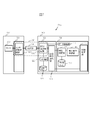
- FIG. 1 is a block diagram of the signal transmission system S1 according to the first embodiment.
- the place where the signal transmission system S1 is installed is not particularly limited, but in the present embodiment, the configuration will be described assuming that the signal transmission system S1 is installed inside the vehicle.
- the signal transmission system S1 includes a sensor module 100 having a built-in sensor 400, an ECU 300 which is an electronic control unit, and a transmission line 200 connecting the sensor module 100 and the ECU 300.
- the sensor module 100 includes a sensor 400 and a sensor communication LSI 500, which is a large scale integration (LSI) for communication.
- the sensor communication LSI 500 includes a sensor transmission / reception circuit 510 that communicates with the ECU 300.
- the ECU 300 includes an ECU communication LSI 600 and a data processing LSI 700.
- the ECU communication LSI 600 includes an ECU transmission / reception circuit 610 that communicates with the sensor module 100, and a transmission characteristic extraction unit 620 that extracts the characteristics of the transmission waveform of the sensing signal sent to the ECU transmission / reception circuit 610.
- the data processing LSI 700 includes a data processing unit 710, a characteristic determination unit 720, a determination standard selection unit 740, and a state determination unit 750. Further, the data processing LSI 700 includes a non-volatile storage device (not shown), and the data set 730 is stored in the storage device.
- the data processing LSI 700 includes a CPU (not shown) which is a central processing unit, a ROM (not shown) which is a read-only storage device, and a RAM (not shown) which is a read / write storage device, and the CPU is stored in the ROM. Is developed in a RAM and executed to realize a data processing unit 710, a characteristic determination unit 720, a determination standard selection unit 740, and a state determination unit 750. However, the data processing LSI 700 uses FPGA (Field Programmable Gate Array), which is a rewritable logic circuit instead of a combination of CPU, ROM, and RAM, and ASIC (Application Specific Integrated Circuit), which is an integrated circuit for specific applications. The function of may be realized.
- FPGA Field Programmable Gate Array
- the sensing data obtained by sensing by the sensor 400 is transmitted to the sensor communication LSI 500.
- This data is received by the sensor transmission / reception circuit 510 inside the sensor communication LSI 500 and transmitted as a sensing signal to the transmission line 200.
- This sensing signal reaches the ECU 300 via the transmission line 200 and is input to the ECU communication LSI 600.
- the sensing signal received by the ECU transmission / reception circuit 610 inside the LSI 600 is transmitted to the data processing unit 710 of the data processing LSI 700.
- the control signal is also transmitted from the data processing unit 710 to the sensor 400.
- the transmission characteristic extraction unit 620 acquires transmission characteristic information such as waveform information and equalizer information of the ECU transmission / reception circuit 610, and sends the transmission characteristic information to the state determination unit 750.
- the equalizer information includes FFE (Feed Forward Equalizer), CLTE (Continuous Time Linear Equalizer), DFE (Decision Feedback Equalizer), and the like.
- the equalizer information also includes a loss compensation coefficient, which is a coefficient used by the ECU transmission / reception circuit 610 for calculation in order to compensate for the loss of the communication signal between the sensor communication LSI 500 and the ECU communication LSI 600. Further, the transmission characteristic extraction unit 620 also has a function of deriving the transition information of the transmission waveform described later.
- the data processing unit 710 performs the original processing of the ECU 300 using the output of the sensor 400.
- the processing content of the data processing unit 710 is not particularly limited, but the data processing unit 710 detects another vehicle from the image obtained by the sensor 400, which is a camera, and estimates the distance to the vehicle, for example. Transmit to other ECUs.
- the characteristic determination unit 720 determines the characteristics of the communication system 250 including the sensor transmission / reception circuit 510, the transmission line 200, and the ECU transmission / reception circuit 610 with SS, which is the lowest operating speed, TT, which is the representative value, and the highest operating speed. Classify into one of the FFs. The operation of the characteristic determination unit 720 will be described in detail later.
- the judgment standard selection unit 740 determines the judgment standard with reference to the data set 730 based on the classification by the characteristic judgment unit 720 and transmits it to the state judgment unit 750. However, the determination criterion selection unit 740 may write the determined determination criterion in a predetermined position of a storage device (not shown). The operation of the state determination unit 750 will be described in detail later.
- the operation frequency of the characteristic determination unit 720 and the determination standard selection unit 740 is relatively low. For example, at least one of the sensor module 100, the transmission line 200, and the ECU 300 when the vehicle equipped with the signal transmission system S1 is shipped from the factory or after shipment. For example, when the module is replaced.
- the state determination unit 750 compares the determination standard transmitted from the determination criterion selection unit 740 with the equalizer coefficient to be described later transmitted from the transmission characteristic extraction unit 620, and determines whether or not the characteristics of the communication system 250 have deteriorated. ..
- the judgment standard is also referred to as a “threshold value”
- the equalizer coefficient is also referred to as a “loss compensation coefficient”.
- the operation frequency of the state determination unit 750 is higher than that of the determination criterion selection unit 740 and the like, for example, every hour, every day, every month, or every inspection of the vehicle equipped with the signal transmission system system S1.
- the state determination unit 750 may notify the data processing unit 710 to that effect, or may notify the other ECUs to that effect.
- FIG. 2 is a diagram showing the relationship between the loss of the communication system 250 and the compensation coefficient under conditions where the power supply voltage and temperature are constant.
- the graph shown in FIG. 2 is obtained by, for example, a preliminary calculation or a preliminary experiment for a large number of signal transmission systems S1 having the same model number.
- the horizontal axis in FIG. 2 indicates the magnitude of the loss of the communication system 250, which is larger toward the right side of the figure.
- the ECU transmission / reception circuit 610 shapes the signal waveform so as to be AD-converted without error by setting the loss compensation coefficient to be larger as the loss of the communication system 250 is larger. Therefore, in FIG. 2, all tend to rise to the right.
- the state determination unit 750 detects the characteristics of the communication system 250 with a light processing load by monitoring the loss correction coefficient.
- the problem is that the relationship between the loss correction coefficient and the loss varies from system to system. For example, if the value “6” of the loss correction coefficient is set as the threshold value, in the case of the standard product TT, the loss 21 dB is set as the threshold value. However, even if the value of the same loss correction coefficient is "6", it is 13 dB when the characteristic is FF and 25 dB when the characteristic is SS, and there is a large variation.
- the characteristics of the communication system 250 are discriminated as initial processing, and an appropriate threshold value of the loss compensation coefficient is set.
- This processor processing is executed by the transmission characteristic extraction unit 620, the characteristic determination unit 720, and the determination standard selection unit 740. Then, in the subsequent steady processing, the threshold value set by the state determination unit 750 and the loss compensation coefficient output by the transmission characteristic extraction unit 620 each time are compared.
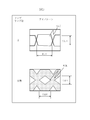
- FIG. 3 is a diagram showing an eye pattern generally used for evaluating transmission characteristics of a communication path, in which the horizontal axis represents time and the vertical axis represents voltage.
- the eye pattern is, so to speak, a large number of overwritten waveforms of received signals, and in the present embodiment, the number of overwritten times is referred to as a “sampling number”.
- the upper part of FIG. 3 shows the case where the sampling number is 2, and the lower part of FIG. 3 shows the case where the sampling number is very large.
- the size of the opening is an important index.
- the opening is a hexagonal region indicated by reference numeral 901E in the upper part of FIG. 3, and a diamond-shaped region indicated by reference numeral 902E in the lower portion of FIG.
- the number of samplings is specified when evaluating the eye pattern.
- the eye pattern condition is specified as "when the number of samplings is 10 to the 12th power, the width 902W of the opening 902E is T1 second or more, and the height 902H is T2V or more".
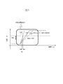
- FIG. 4 is a conceptual diagram showing the estimation of the opening of the eye pattern.
- FIG. 4 is composed of a diagram showing an eye pattern shown in the upper left, an estimation diagram having a width of 902W shown in the lower left, and an estimation diagram having a height of 902H shown in the upper right.
- the number of eye pattern samplings is represented by the variable “N”.
- the "Log" shown in each graph of FIG. 4 has a common logarithm, that is, a base of 10.
- the two estimation diagrams shown in FIG. 4 are also called “bathtub curves" because they are similar in shape.
- the width 902W is NW2 when the sampling number N is 10 squared, that is, 100 times
- the width 902W is 902W when the sampling number N is 10 squared, that is, 10000 times. Is NW4
- the width 902W is NW12 when the sampling number N is 10 to the 12th power.
- the height 902H shown in the upper right of FIG. 4 when the sampling number N is 10 squared, that is, when the height 902H is NH2 and the sampling number N is 10 times, that is, 10000 times. It is shown that the height 902H is NH4 when the height 902H is NH4 and the sampling number N is 10 to the 12th power.
- the slope of the illustrated straight line is estimated with a small number of samplings, and the width and height of the opening of the eye pattern are calculated with a large number of samplings.
- 10 to 12 Calculate the width and height of the riding eye pattern.
- the approximation is performed by a linear function, but may be approximated by a quadratic function.
- FIG. 5 is a diagram showing the determination of the characteristics of the communication system.
- Each of the width and height at the opening of the eye pattern corresponds to the magnitude of random jitter (RJ) and random noise (RN), respectively.
- RJ random jitter
- RN random noise
- the slew rate is calculated as RN / RJ.
- the data set 730 for example, it is a combination of characteristics and a slew rate, and specifically, it is information that "SS is 0.8, TT is 1.0, and FF is 1.2".
- the characteristic determination unit 7720 compares the calculated slew rate with the information described in the data set 730 to determine the characteristics of the communication system 250. This slew rate is also referred to as "transmission waveform transition information".
- the transmission characteristic extraction unit 620 even calculates the slew rate, and the characteristic determination unit 720 only discriminates the characteristics.
- the data signal used by the transmission characteristic extraction unit 620 for evaluation of the eye pattern with a small number of samplings may be a signal specially prepared for evaluation of system characteristics, but transmission such as a sensing signal output by the sensor 400 may be used. Any signal passing through road 200 may be used.
- the data set 730 stores a predetermined loss threshold value and information indicating the relationship between the loss and the loss compensation coefficient for each characteristic shown in FIG.
- the determination criterion selection unit 740 determines the threshold value with reference to the data set 730. For example, when the predetermined loss threshold is 21 dB, the threshold is "6" when the characteristic is TT, the threshold is "4" when the characteristic is SS, and the threshold is "10" when the characteristic is FF. It is determined.
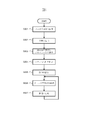
- FIG. 6 is a flowchart showing the operation of the signal transmission system S1.
- steps S931 to S935 are initial processes
- steps S936 to S937 are steady processes.
- this flowchart is described to clarify the context of each process, and does not indicate that each process is continuous in chronological order. In particular, there may be an interval of days, months, or years between the initial treatment and the routine treatment.
- step S931 the transmission characteristic extraction unit 620 evaluates the bathtub curve. Specifically, the transmission characteristic extraction unit 620 creates an eye pattern with a small number of samplings, for example, 100 sampling times and 10,000 sampling times, and evaluates the width and height of the opening. In the following step S932, the transmission characteristic extraction unit 620 calculates the slopes of the two graphs shown in FIG. 4, that is, the coefficients of the approximate straight line. In the following step S932, the transmission characteristic extraction unit 620 calculates the width 902W and the height 902H of the eye pattern at the specified sampling number using the coefficients calculated in step S932. Further, the transmission characteristic extraction unit 620 calculates the slew rate, which is the ratio of the width 902W and the height 902H.
- the characteristic determination unit 720 determines the characteristics of the system with reference to the data set 730.
- the characteristic determination unit 720 selects, for example, a characteristic having a value closest to the calculated slew rate.
- the determination criterion selection unit 740 determines the threshold value with reference to the data set 730 based on the characteristics determined by the characteristic determination unit 720.
- the state determination unit 750 reads the equalizer coefficient set in the ECU transmission / reception circuit 610 from the transmission characteristic extraction unit 620.
- the state determination unit 750 evaluates the system by comparing the threshold value set in step S935 with the equalizer coefficient read in step S936.
- the state determination unit 750 determines that an abnormality has occurred when the equalizer coefficient read in step S936 is larger than the threshold value, and determines that it is normal when the equalizer coefficient read in Tep S936 is equal to or less than the threshold value. do.
- the state determination unit 750 returns to step S936 when the process of step S937 is completed.
- step S936 may be started on condition that a predetermined signal is input from the outside. That is, the steady processing of steps S936 to S937 may be started when the initial processing shown in steps S931 to S935 is completed and a predetermined signal is input from the outside.
- the ECU 300 which is an electronic control device, is based on an ECU transmission / reception circuit 610 that receives a data signal from a sensor module 100, which is an external device, via a transmission line 200, and waveform transition information in the data signal, that is, a through rate.
- the state of the communication system 250 is determined based on the determination criterion selection unit 740 for determining the determination criterion, that is, the threshold value, and the transmission waveform characteristics in the data signal, that is, the loss compensation coefficient of the equalizer and the above-mentioned threshold value with reference to the data set 730.
- a state determination unit 750 and a state determination unit 750 are provided.
- the ECU 300 can make a diagnosis corresponding to the variation in the characteristics of the device related to transmission / reception, that is, the sensor module 100, the ECU 300, and the communication system 250 including the transmission line 200. This makes it possible to improve the diagnostic accuracy.
- the threshold value according to the characteristics of the communication system 250, it is possible to obtain the same diagnostic accuracy as in the case where the characteristics of the communication system 250 have little variation.
- the device variation generally includes PVT (process, power supply voltage, temperature), but in the present embodiment, the variation is suppressed by setting the allowable range at the time of diagnosis for the power supply voltage and temperature, and the diagnostic accuracy.
- the determination method in the present embodiment also includes the characteristics of the transmission line between the sensor communication LSI 500 and the ECU communication LSI 600. Therefore, for example, when the transmission line 200 uses a board, a connector, a cable, a relay connector, or the like, transition information of a data transmission waveform affected by those characteristics can be acquired. Therefore, it is possible to select a criterion including process information of the device involved in communication.
- the transmission waveform characteristic in the data signal is an equalizer waveform adjustment setting value for adjusting the waveform of the data signal, that is, a loss compensation coefficient.
- the state determination unit 750 determines the state of the communication unit based on the transmission waveform characteristics and the determination criteria.
- the ECU 300 estimates the characteristics of the eye pattern in the third sampling number N3 by using the eye pattern by the first sampling number N1 and the eye pattern by the second sampling number N2, and waveform transition information.
- the transmission characteristic extraction unit 620 for calculating the above is provided.
- N1 is, for example, 10 squared
- N2 is, for example, 10 to the 4th power
- N3 is, for example, 10 to the 12th power
- N3 is larger than N1 and N2. Therefore, the characteristics of the communication system 250 can be determined in a short time in the initial processing.
- Modification 1 In the first embodiment, attention is paid to the loss correction coefficient of the equalizer, which is a process of shaping the signal when the ECU 300 becomes the receiving side of the communication.
- a similar method may be applied to signal shaping when the ECU 300 is on the transmitting side, that is, pre-emphasis or de-emphasis.
- the same operation and effect as in the first embodiment can be obtained not only when the ECU 300 is on the receiving side but also when it is on the transmitting side.
- the transmission waveform characteristics of the data signal include pre-emphasis and de-emphasis setting values for adjusting the waveform of the data signal. Therefore, the ECU 300 can perform the same diagnosis as in the first embodiment not only when receiving data but also when transmitting data.
- FIG. 7 is a diagram showing a configuration of the signal transmission system S1b in the second modification.
- the ECU communication LSI 600 further includes a recording unit 628 for recording the loss correction coefficient.
- the recording unit 628 acquires the loss correction coefficient from the ECU transmission / reception circuit 610 and records it as a log 629.
- the log 629 is recorded in a non-volatile storage device (not shown).
- the ECU 300 includes a recording unit 628 that stores log data of transmission waveform characteristics related to data signals. Therefore, the log data can be used for ex post facto analysis.
- the transition information of the transmission waveform derived by the transmission characteristic extraction unit 620 may include overshoot and undershoot information.
- the characteristics of the communication system 250 may be specified from the overshoot and undershoot information, that is, the voltage value and the time information.
- the slew rate value may be classified and the process information may be determined even if the data set is not 730.
- the transmission characteristic extraction unit 620 may directly acquire the process information of the sensor transmission / reception circuit 510 of the sensor module 100 and the process information of the ECU transmission / reception circuit 610 from the outside, or utilize technologies such as machine learning and AI to process information. And communication quality diagnosis may be performed.
- the characteristics of the communication system 250 are classified into three types. However, the number of classifications is not limited to 3, and may be 2 or more. Further, the determination criterion selection unit 740 selects one of three threshold values for the communication system 250 based on the slew rate value, but an intermediate value may be used as the threshold value by a method such as proportional complementation.
- FIGS. 8 to 9 A second embodiment of the signal transmission system will be described with reference to FIGS. 8 to 9.
- the same components as those in the first embodiment are designated by the same reference numerals, and the differences will be mainly described.
- the points not particularly described are the same as those in the first embodiment.
- This embodiment differs from the first embodiment mainly in that voltage and temperature are taken into consideration.
- FIG. 8 is a configuration diagram of the signal transmission system S2 according to the second embodiment.
- the sensor module 100 further includes a power supply voltage sensor 830 and a temperature sensor 840
- the ECU 300 further includes a power supply voltage sensor 810 and a temperature sensor 820. And further prepare.
- the sensing signals of the power supply voltage sensors 810 and 830 and the temperature sensors 820 and 840 are input to the determination standard selection unit 740 of the ECU 300.
- the data set 730 of the present embodiment stores information indicating the relationship between the loss and the loss compensation coefficient corresponding to each combination of the power supply voltage and the temperature for each of the characteristics of SS, TT, and FF of the communication system 250. ing.
- the determination criterion selection unit 740 in the present embodiment determines the threshold value using not only the characteristics of the communication system 250 determined by the characteristic determination unit 720 but also the information of the power supply voltage and the temperature. That is, in the present embodiment, the determination standard selection unit 740 sets the threshold value according to the power supply voltage and the temperature each time the state determination unit 750 makes a determination, not only once as the initial process.
- FIG. 9 is a flowchart showing the operation of the signal transmission system S2 in the second embodiment.
- the same process as that of the first embodiment is assigned the same step number, and the description thereof will be omitted.
- step S935 is followed by step S935a.
- steps S931 to S934 are initial processes
- steps S935a to S937 are steady processes.
- step S935a the determination criterion selection unit 740 reads the sensing signals of the power supply voltage sensors 810 and 830 and the temperature sensors 820 and 840, and reads the voltage and temperature values.
- the determination criterion selection unit 740 refers to the data set 730 and sets the corresponding loss compensation coefficient, that is, the threshold value, based on the voltage and temperature combination read in step S935a and the predetermined loss threshold value. do. This threshold is used in step S937.
- the processing of steps S936 and S937 is the same as that of the first embodiment. However, when the process of step S937 is completed, the process proceeds to step S935a.
- the determination criterion selection unit 740 of the ECU 300 determines the determination criterion based on the power supply voltage and temperature information of the sensor module 100 and the ECU 100. Therefore, the information at the time of selecting the judgment standard by the judgment standard selection unit 740 increases, and highly accurate diagnosis becomes possible.
- FIG. 1 A third embodiment of the signal transmission system will be described with reference to FIG.
- the same components as those in the first embodiment are designated by the same reference numerals, and the differences will be mainly described.
- the points not particularly described are the same as those in the first embodiment.
- the present embodiment differs from the first embodiment mainly in that a plurality of communication systems are evaluated.
- FIG. 10 is a configuration diagram of the signal transmission system S3 according to the third embodiment.
- the second sensor module 101 is connected to the ECU 330 via the second transmission line 201.
- the ECU 330 further includes an ECU second communication LSI 601 and a second data processing LSI 701 in addition to the configuration of the first embodiment.
- the second sensor module 101 includes a sensor 401 and a second sensor communication LSI 501, and the second sensor communication LSI 501 includes a sensor transmission / reception circuit 511.
- the ECU second communication LSI 601 includes an ECU transmission / reception circuit 611 and a transmission characteristic extraction unit 621.
- the second data processing LSI 701 includes a data processing unit 711, a characteristic determination unit 721, a determination standard selection unit 741, and a state determination unit 751.
- the sensor transmission / reception circuit 511, the second transmission line 201, and the ECU transmission / reception circuit 611 are collectively referred to as a second communication system 251.
- the configuration and operation of the ECU second communication LSI 601 are substantially the same as those of the ECU communication LSI 600, and the configuration and operation of the second data processing LSI 701 are substantially the same as those of the data processing LSI 700.
- the predetermined loss included in the data set 731 of the second data processing LSI 701 is a value corresponding to the second communication system 251.
- the ECU 330 includes an ECU transmission / reception circuit 611, which is a second receiving unit that receives a second data signal from a second sensor module 101, which is a second external device, via a second transmission line 201, and a second data signal.
- a unit 751 is provided. Therefore, since each sensor has a determination criterion selection unit, a transmission / reception circuit, and a transmission path, it is possible to make a diagnosis in each transmission system, and it is possible to identify an abnormal route after the diagnosis.
- FIG. 1 A fourth embodiment of the signal transmission system will be described with reference to FIG.
- the same components as those in the first embodiment are designated by the same reference numerals, and the differences will be mainly described.
- the points not particularly described are the same as those in the first embodiment.
- the present embodiment is different from the first embodiment in that the deterioration of the communication system is mainly detected on the sensor side.
- FIG. 11 is a configuration diagram of the signal transmission system S4 according to the fourth embodiment.
- the transmission characteristic extraction unit 620, the characteristic determination unit 720, the data set 730, the determination standard selection unit 740, and the state determination unit 750 included in the ECU 300 are sensor modules 140. Have moved to. However, since the operation of each configuration is the same as that of the first embodiment, the description thereof will be omitted.
- the calculation load of the ECU 300 can be reduced. Further, the communication state can be determined for the signal from the ECU 300 to the sensor module 100.
- the configuration of the functional block is only an example.
- Several functional configurations shown as separate functional blocks may be integrally configured, or the configuration represented by one functional block diagram may be divided into two or more functions. Further, a configuration in which a part of the functions of each functional block is provided in another functional block may be provided.
- the program is stored in a ROM (not shown), but the program may be stored in a non-volatile storage device.
- the ECU may include an input / output interface (not shown), and a program may be read from another device via the input / output interface and a medium available to the ECU when necessary.
- the medium refers to, for example, a storage medium that can be attached to and detached from an input / output interface, or a communication medium, that is, a network such as wired, wireless, or optical, or a carrier wave or digital signal that propagates in the network.
- some or all of the functions realized by the program may be realized by the hardware circuit or FPGA.
Landscapes
- Engineering & Computer Science (AREA)
- Computer Networks & Wireless Communication (AREA)
- Signal Processing (AREA)
- Power Engineering (AREA)
- Cable Transmission Systems, Equalization Of Radio And Reduction Of Echo (AREA)
- Monitoring And Testing Of Transmission In General (AREA)
- Dc Digital Transmission (AREA)
Abstract
電子制御装置は、外部装置から伝送路を介してデータ信号を受信する受信部と、データ信号における波形の遷移情報に基づいて判定基準を決定する判定基準選択部と、データ信号における伝送波形特性と判定基準に基づいて、外部装置、受信部、および伝送路を含む通信システムの状態を判定する状態判定部と、を備える。
Description
本発明は、電子制御装置、および判定方法に関する。
自動運転や先進運転支援システム向けの電子制御装置は、センサによる運転制御が求められている。センサからのデータ信号の高速化に伴い、伝送路の劣化による信号品質の低下が顕在化してしまう。その中で、センサとECU間は高信頼な通信を実現する必要があり、データ伝送変数を診断基準と比較することで、通信品質診断を行う技術が知られている。特許文献1には、診断対象経路上の送受信デバイスからデータ伝送路の特性によって設定されるデータ伝送変数を採取する採取部と、採取された前記データ伝送変数に基づき、データ伝送変数の値と良否判定情報とを対応付けて構成された診断基準情報を参照することで、前記診断対象経路の診断を行なう診断部とを備えることを特徴とする診断装置が開示されている。
特許文献1に記載されている発明では、製品ごとのばらつきが考慮されていない。
本発明の第1の態様による電子制御装置は、外部装置から伝送路を介してデータ信号を受信する受信部と、前記データ信号における波形の遷移情報に基づいて判定基準を決定する判定基準選択部と、前記データ信号における伝送波形特性と前記判定基準に基づいて、前記外部装置、前記受信部、および前記伝送路を含む通信システムの状態を判定する状態判定部と、を備える。
本発明の第2の態様による判定方法は、外部装置から伝送路を介してデータ信号を受信する受信部を有するコンピュータが実行する判定方法であって、前記データ信号における波形の遷移情報に基づいて判定基準を決定することと、前記データ信号における伝送波形特性と前記判定基準に基づいて、前記外部装置、前記受信部、および前記伝送路を含む通信システムの状態を判定することとを含む。
本発明の第2の態様による判定方法は、外部装置から伝送路を介してデータ信号を受信する受信部を有するコンピュータが実行する判定方法であって、前記データ信号における波形の遷移情報に基づいて判定基準を決定することと、前記データ信号における伝送波形特性と前記判定基準に基づいて、前記外部装置、前記受信部、および前記伝送路を含む通信システムの状態を判定することとを含む。
本発明によれば、送受信に関わる装置および伝送路を含む通信システム全体の特性のばらつきに対応する診断ができる。上記した以外の課題、構成および効果は、以下の発明を実施するための形態の説明により明らかにされる。
以下、図面を参照して本発明の実施形態を説明する。実施例は、本発明を説明するための例示であって、説明の明確化のため、適宜、省略および簡略化がなされている。本発明は、他の種々の形態でも実施することが可能である。特に限定しない限り、各構成要素は単数でも複数でも構わない。
図面において示す各構成要素の位置、大きさ、形状、範囲などは、発明の理解を容易にするため、実際の位置、大きさ、形状、範囲などを表していない場合がある。このため、本発明は、必ずしも、図面に開示された位置、大きさ、形状、範囲などに限定されない。各種情報の例として、「テーブル」、「リスト」、「キュー」等の表現にて説明することがあるが、各種情報はこれら以外のデータ構造で表現されてもよい。例えば、「XXテーブル」、「XXリスト」、「XXキュー」等の各種情報は、「XX情報」としてもよい。識別情報について説明する際に、「識別情報」、「識別子」、「名」、「ID」、「番号」等の表現を用いるが、これらについてはお互いに置換が可能である。
同一あるいは同様の機能を有する構成要素が複数ある場合には、同一の符号に異なる添字を付して説明する場合がある。また、これらの複数の構成要素を区別する必要がない場合には、添字を省略して説明する場合がある。実施例において、プログラムを実行して行う処理について説明する場合がある。ここで、計算機は、プロセッサ(例えばCPU、GPU)によりプログラムを実行し、記憶資源(例えばメモリ)やインターフェースデバイス(例えば通信ポート)等を用いながら、プログラムで定められた処理を行う。そのため、プログラムを実行して行う処理の主体を、プロセッサとしてもよい。同様に、プログラムを実行して行う処理の主体が、プロセッサを有するコントローラ、装置、システム、計算機、ノードであってもよい。プログラムを実行して行う処理の主体は、演算部であれば良く、特定の処理を行う専用回路を含んでいてもよい。ここで、専用回路とは、例えばFPGA(Field Programmable Gate Array)やASIC(Application Specific Integrated Circuit)、CPLD(Complex Programmable Logic Device)等である。
プログラムは、プログラムソースから計算機にインストールされてもよい。プログラムソースは、例えば、プログラム配布サーバまたは計算機が読み取り可能な記憶メディアであってもよい。プログラムソースがプログラム配布サーバの場合、プログラム配布サーバはプロセッサと配布対象のプログラムを記憶する記憶資源を含み、プログラム配布サーバのプロセッサが配布対象のプログラムを他の計算機に配布してもよい。また、実施例において、2以上のプログラムが1つのプログラムとして実現されてもよいし、1つのプログラムが2以上のプログラムとして実現されてもよい。
―第1の実施の形態―
以下、図1~図6を参照して、信号伝送システムの第1の実施の形態を説明する。
以下、図1~図6を参照して、信号伝送システムの第1の実施の形態を説明する。
(構成)
図1は、第1の実施の形態における信号伝送システムS1の構成図である。信号伝送システムS1が設置される場所は特に限定されないが、本実施の形態では信号伝送システムS1が車両の内部に設置されるとして構成を説明する。信号伝送システムS1は、センサ400を内蔵するセンサモジュール100と、電子制御装置(Electronic Control Unit)であるECU300と、センサモジュール100およびECU300を接続する伝送路200とを含む。センサモジュール100は、センサ400と、通信用の大規模集積回路(Large Scale Integration:LSI)であるセンサ通信LSI500とを備える。センサ通信LSI500は、ECU300との通信を行うセンサ送受信回路510を備える。
図1は、第1の実施の形態における信号伝送システムS1の構成図である。信号伝送システムS1が設置される場所は特に限定されないが、本実施の形態では信号伝送システムS1が車両の内部に設置されるとして構成を説明する。信号伝送システムS1は、センサ400を内蔵するセンサモジュール100と、電子制御装置(Electronic Control Unit)であるECU300と、センサモジュール100およびECU300を接続する伝送路200とを含む。センサモジュール100は、センサ400と、通信用の大規模集積回路(Large Scale Integration:LSI)であるセンサ通信LSI500とを備える。センサ通信LSI500は、ECU300との通信を行うセンサ送受信回路510を備える。
ECU300は、ECU通信LSI600と、データ処理LSI700とを備える。ECU通信LSI600は、センサモジュール100との通信を行うECU送受信回路610と、ECU送受信回路610に送られたセンシング信号の伝送波形の特性を抽出する伝送特性抽出部620とを備える。データ処理LSI700は、データ処理部710、特性判定部720、判定基準選択部740、および状態判定部750を備える。またデータ処理LSI700は不図示の不揮発性の記憶装置を備え、その記憶装置にはデータセット730が格納される。
データ処理LSI700は、中央演算装置である不図示のCPU、読み出し専用の記憶装置である不図示のROM、および読み書き可能な記憶装置である不図示のRAMを備え、CPUがROMに格納されるプログラムをRAMに展開して実行することで、データ処理部710、特性判定部720、判定基準選択部740、および状態判定部750を実現する。ただしデータ処理LSI700は、CPU、ROM、およびRAMの組み合わせの代わりに書き換え可能な論理回路であるFPGA(Field Programmable Gate Array)や特定用途向け集積回路であるASIC(Application Specific Integrated Circuit)を用いてこれらの機能を実現してもよい。
センサ400がセンシングして得られたセンシングデータは、センサ通信LSI500に伝達される。このデータはセンサ通信LSI500の内部にあるセンサ送受信回路510で受信されて、伝送路200にセンシング信号として送信される。このセンシング信号は、伝送路200を介してECU300に到達し、ECU通信LSI600に入力される。LSI600の内部にあるECU送受信回路610で受信されたセンシング信号は、データ処理LSI700のデータ処理部710に伝達する。なお、センサ400からデータ処理部710までのセンシング信号の伝達経路について説明したが、データ処理部710からセンサ400への制御信号の伝達も行われる。
伝送特性抽出部620は、波形情報やECU送受信回路610のイコライザ情報などの伝送特性情報を取得し、その伝送特性情報を状態判定部750に送る。なおイコライザ情報とは、FFE(Feed Forward Equalizer)、CLTE(Continuous Time Linear Equalizer)、DFE(Decision Feedback Equalizer)などである。またこのイコライザ情報には、センサ通信LSI500とECU通信LSI600との間における通信信号の損失を補償するためにECU送受信回路610が演算に用いる係数である損失補償係数も含まれる。さらに伝送特性抽出部620は、後述する伝送波形の遷移情報を導出する機能も有する。
データ処理部710は、センサ400の出力を利用するECU300の本来的な処理を行う。データ処理部710の処理内容は特に限定されないが、データ処理部710はたとえば、カメラであるセンサ400が撮影して得られた画像から他の車両を検出し、その車両までの距離を推定して他のECUに伝達する。
特性判定部720は、センサ送受信回路510、伝送路200、およびECU送受信回路610を含めた通信システム250の特性を動作速度の最低値であるSS、代表値であるTT、動作速度の最高値であるFFのいずれかに分類する。特性判定部720の動作は後に詳述する。
判定基準選択部740は、特性判定部720による分類に基づき、データセット730を参照して判定基準を決定して状態判定部750に送信する。ただし判定基準選択部740は、決定した判定基準を不図示の記憶装置の所定の位置に書き込んでもよい。状態判定部750の動作は後に詳述する。なお特性判定部720および判定基準選択部740の動作頻度は比較的低く、たとえば当該信号伝送システムS1を搭載する車両が工場出荷される際や出荷後にセンサモジュール100、伝送路200、ECU300の少なくともいずれかが交換される際などである。
状態判定部750は、判定基準選択部740から送信された判定基準と、伝送特性抽出部620から送信される、後述するイコライザ係数とを比較し、通信システム250の特性の劣化の有無を判断する。なお以下では、判定基準を「閾値」とも呼び、イコライザ係数は「損失補償係数」とも呼ぶ。状態判定部750の動作頻度は判定基準選択部740などよりは高く、たとえば1時間ごと、1日ごと、1カ月ごと、または当該信号伝送システムシステムS1を搭載する車両の点検ごとである。状態判定部750は、通信システム250の特性が劣化したと判断する場合は、データ処理部710にその旨を伝達してもよいし、他のECUにその旨を伝達してもよい。
(特性ばらつきと状態判定の関係)
各機能の詳細な説明をする前に、通信システム250の特性のばらつきが異常検出に与える影響を説明する。図2は、電源電圧や温度が一定の条件下における、通信システム250の損失と補償係数の関係を示す図である。図2に示すグラフは、たとえば同一の型番を有する大量の信号伝送システムS1を対象として事前の演算や事前の実験などにより得られたものである。図2における横軸は、通信システム250の損失の大きさを示しており、図示右側ほど大きい。図2における縦軸は、ECU送受信回路610に備えられるイコライザの損失補償係数の大きさを示しており、図示上部ほど大きい。ECU送受信回路610は、通信システム250の損失が大きいほど損失補償係数を大きく設定することで信号波形を誤りなくAD変換されるように整形する。そのため図2では、全てが右肩上がりの傾向を有する。
各機能の詳細な説明をする前に、通信システム250の特性のばらつきが異常検出に与える影響を説明する。図2は、電源電圧や温度が一定の条件下における、通信システム250の損失と補償係数の関係を示す図である。図2に示すグラフは、たとえば同一の型番を有する大量の信号伝送システムS1を対象として事前の演算や事前の実験などにより得られたものである。図2における横軸は、通信システム250の損失の大きさを示しており、図示右側ほど大きい。図2における縦軸は、ECU送受信回路610に備えられるイコライザの損失補償係数の大きさを示しており、図示上部ほど大きい。ECU送受信回路610は、通信システム250の損失が大きいほど損失補償係数を大きく設定することで信号波形を誤りなくAD変換されるように整形する。そのため図2では、全てが右肩上がりの傾向を有する。
また前述のとおり状態判定部750は、損失補正係数を監視することで軽い処理負荷で通信システム250の特性を検出する。ここで、損失補正係数と損失の関係にシステムごとにばらつきがある点が問題となる。たとえば損失補正係数の値「6」を閾値にすると、標準品であるTTの場合には損失21dBを閾値に設定したことになる。しかし同じ損失補正係数の値が「6」でも、特性がFFの場合には13dB、特性がSSの場合には25dBとなり大きなばらつきがある。もちろんこの場合であっても、損失が12dB以上に悪化した場合に検出することが要求事項であれば、13、21、25のいずれも12以上なので検出ができることには間違いはない。しかし過剰な品質を要求することになり経済的ではない。
そこで本実施の形態では、初期処理として通信システム250の特性を判別して、適切な損失補償係数の閾値を設定する。この処理器処理は、伝送特性抽出部620、特性判定部720、および判定基準選択部740が実行する。そしてその後の定常処理では、状態判定部750が設定された閾値と伝送特性抽出部620がその都度出力する損失補償係数とを比較する。
(特性の判別)
図3は、一般に通信路の伝送特性評価に用いられるアイパターンを示す図であり、横軸は時間を示し縦軸は電圧を示す。アイパターンはいわば、受信した信号の波形を多数重ね書きしたものであり、本実施の形態ではこの重ね書きの回数を「サンプリング数」と呼ぶ。図3の上部はサンプリング数が2の場合を示し、図3の下部はサンプリング数が非常に大きい場合を示す。アイパターンは開口部の寸法が重要な指標である。開口部とは、図3の上部では符号901Eで示す六角形の領域、図3の下部では符号902Eで示すひし形の領域である。
図3は、一般に通信路の伝送特性評価に用いられるアイパターンを示す図であり、横軸は時間を示し縦軸は電圧を示す。アイパターンはいわば、受信した信号の波形を多数重ね書きしたものであり、本実施の形態ではこの重ね書きの回数を「サンプリング数」と呼ぶ。図3の上部はサンプリング数が2の場合を示し、図3の下部はサンプリング数が非常に大きい場合を示す。アイパターンは開口部の寸法が重要な指標である。開口部とは、図3の上部では符号901Eで示す六角形の領域、図3の下部では符号902Eで示すひし形の領域である。
図3の上部と下部の比較から明らかなように、同一の通信システムを用いる場合であっても、重ね書きの回数が多いほど開口部は狭くなる。そのため一般に、アイパターンの評価に際してはサンプリング数が指定される。たとえばアイパターンの条件が、「サンプリング数が10の12乗回において、開口部902Eの幅902WがT1秒以上、高さ902HがT2V以上」などと指定される。このとき、膨大な数のサンプリング数が求められた場合に、試験が長時間に及ぶ問題が生じる。本実施の形態では次の手法により解決した。
図4は、アイパターンの開口部の推定を示す概念図である。図4は、左上に示すアイパターンを示す図と、左下に示す幅902Wの推定図と、右上に示す高さ902Hの推定図とから構成される。図4では、アイパターンのサンプリング数を変数「N」で表している。本願の発明者らは鋭意検討の結果、アイパターンの幅902Wおよび高さ902Hは、サンプリング数「N」との相関を有することを見出した。図4のそれぞれのグラフに示す「Log」は常用対数、すなわち底が10である。なお図4に示す2つの推定図は、形状が似ていることから「バスタブ曲線」とも呼ばれる。
図4の左下に示す幅902Wの推定図では、サンプリング数Nが10の2乗、すなわち100回の場合に幅902WがNW2、サンプリング数Nが10の4乗、すなわち10000回の場合に幅902WがNW4、サンプリング数Nが10の12乗回の場合に幅902WがNW12であることを示している。図4の右上に示す高さ902Hの推定図では、サンプリング数Nが10の2乗、すなわち100回の場合に高さ902HがNH2、サンプリング数Nが10の4乗、すなわち10000回の場合に高さ902HがNH4、サンプリング数Nが10の12乗回の場合に高さ902HがNH12であることを示している。
本実施の形態では、少ないサンプリング回数で図示する直線の傾きを推定して、多いサンプリング回数におけるアイパターンの開口部の幅および高さを算出する。たとえば、サンプリング数10の12乗回のアイパターンを評価する場合であっても、実際には10の2乗回および10の4乗回のアイパターンのみを実際に作成することで、10の12乗回のアイパターンの幅および高さを算出する。なお図4に示す例では、1次関数で近似しているが二次関数で近似してもよい。
図5は、通信システムの特性の判別を示す図である。アイパターンの開口部における幅および高さのそれぞれは、ランダムジッタ(RJ)とランダムノイズ(RN)のそれぞれの大きさに対応する。そしてこれらの比が通信システムの特性を決定づけるスルーレートである。具体的には、スルーレートはRN/RJとして算出される。データセット730には、たとえば特性とスルーレートの組合せであり具体的には、「SSは0.8、TTは1.0、FFは1.2」という情報である。特性判定部7720は、算出されたスルーレートとデータセット730に記載された情報とを比較して、通信システム250の特性を判別する。なおこのスルーレートは、「伝送波形の遷移情報」とも呼ばれる。
なお上述した通信システム250の特性の判別処理において、伝送特性抽出部620はスルーレートの算出までを行い、特性判定部720は特性の判別だけを行う。また伝送特性抽出部620が少ないサンプリング数でのアイパターンの評価のために使用するデータ信号は、システム特性の評価のために特別に用意した信号でもよいが、センサ400が出力するセンシング信号など伝送路200を通過するどのような信号でもよい。
(判定基準の選択)
データセット730には、あらかじめ定められた損失の閾値、および図2に示す特性ごとの損失と損失補償係数の関係を示す情報が格納される。判定基準選択部740は、特性判定部720が通信システム250の特性を選択すると、データセット730を参照して閾値を決定する。たとえばあらかじめ定められた損失の閾値が21dBの場合は、特性がTTの場合は閾値が「6」、特性がSSの場合は閾値が「4」、特性がFFの場合は閾値が「10」に決定される。
データセット730には、あらかじめ定められた損失の閾値、および図2に示す特性ごとの損失と損失補償係数の関係を示す情報が格納される。判定基準選択部740は、特性判定部720が通信システム250の特性を選択すると、データセット730を参照して閾値を決定する。たとえばあらかじめ定められた損失の閾値が21dBの場合は、特性がTTの場合は閾値が「6」、特性がSSの場合は閾値が「4」、特性がFFの場合は閾値が「10」に決定される。
(フローチャート)
図6は、信号伝送システムS1の動作を示すフローチャートである。以下に説明する各ステップのうち、ステップS931~S935が初期処理であり、ステップS936~S937が定常処理である。また本フローチャートは各処理の前後関係を明示するために記載しており、各処理が時系列的に連続していることを示すものではない。特に初期処理と定常処理との間は、数日、数か月、または数年の間隔を有する場合もある。
図6は、信号伝送システムS1の動作を示すフローチャートである。以下に説明する各ステップのうち、ステップS931~S935が初期処理であり、ステップS936~S937が定常処理である。また本フローチャートは各処理の前後関係を明示するために記載しており、各処理が時系列的に連続していることを示すものではない。特に初期処理と定常処理との間は、数日、数か月、または数年の間隔を有する場合もある。
ステップS931では、伝送特性抽出部620がバスタブ曲線の評価を行う。具体的には、伝送特性抽出部620が少ないサンプリング数、たとえば100回と10000回のサンプリング数でアイパターンを作成して開口部の横幅および高さを評価する。続くステップS932では伝送特性抽出部620は、図4に示す2つのグラフの傾き、すなわち近似直線の係数を算出する。続くステップS932では伝送特性抽出部620は、ステップS932において算出した係数を用いて、規定のサンプリング数におけるアイパターンの幅902Wおよび高さ902Hを算出する。さらに伝送特性抽出部620は、幅902Wと高さ902Hの比であるスルーレートを算出する。
続くステップS934では特性判定部720は、データセット730を参照してシステムの特性を判定する。特性判定部720はたとえば、算出したスルーレートに最も近い値を有する特性を選択する。続くステップS935では判定基準選択部740は、特性判定部720が判定した特性に基づき、データセット730を参照して閾値を決定する。続くステップS936では状態判定部750は、伝送特性抽出部620からECU送受信回路610において設定されているイコライザ係数を読み取る。続くステップS937では状態判定部750は、ステップS935において設定された閾値と、ステップS936において読み取ったイコライザ係数とを比較してシステムを評価する。
具体的には状態判定部750は、ステップS936において読み取ったイコライザ係数が閾値よりも大きい場合には異常が発生したと判断し、テップS936において読み取ったイコライザ係数が閾値以下の場合には正常と判断する。状態判定部750は、ステップS937の処理が完了するとステップS936に戻る。なおステップS936は外部から所定の信号が入力されることを条件に実行が開始されてもよい。すなわちステップS936~S937の定常処理は、ステップS931~S935に示す初期処理が完了しており、かつ外部から所定の信号が入力された場合に実行が開始されてもよい。
上述した第1の実施の形態によれば、次の作用効果が得られる。
(1)電子制御装置であるECU300は、外部装置であるセンサモジュール100から伝送路200を介してデータ信号を受信するECU送受信回路610と、データ信号における波形の遷移情報、すなわちスルーレートに基づいて、データセット730を参照して判定基準すなわち閾値を決定する判定基準選択部740と、データ信号における伝送波形特性、すなわちイコライザの損失補償係数と前述の閾値に基づいて、通信システム250の状態を判定する状態判定部750と、を備える。そのためECU300は、送受信に関わる装置、すなわちセンサモジュール100とECU300および伝送路200を含む通信システム250の特性のばらつきに対応する診断ができる。これにより診断精度を向上することができる。換言すると本実施の形態では、通信システム250の特性にあわせて閾値を設定することで、通信システム250の特性のばらつきが少ない場合と同様の診断の精度を得ることができる。
(1)電子制御装置であるECU300は、外部装置であるセンサモジュール100から伝送路200を介してデータ信号を受信するECU送受信回路610と、データ信号における波形の遷移情報、すなわちスルーレートに基づいて、データセット730を参照して判定基準すなわち閾値を決定する判定基準選択部740と、データ信号における伝送波形特性、すなわちイコライザの損失補償係数と前述の閾値に基づいて、通信システム250の状態を判定する状態判定部750と、を備える。そのためECU300は、送受信に関わる装置、すなわちセンサモジュール100とECU300および伝送路200を含む通信システム250の特性のばらつきに対応する診断ができる。これにより診断精度を向上することができる。換言すると本実施の形態では、通信システム250の特性にあわせて閾値を設定することで、通信システム250の特性のばらつきが少ない場合と同様の診断の精度を得ることができる。
なおデバイスばらつきは、一般にPVT(プロセス、電源電圧、温度)があるが、本実施の形態では、電源電圧と温度については、診断時の許容範囲を設定することで、ばらつきを抑制し、診断精度を確保する。また本実施の形態における判定方法では、センサ通信LSI500からECU通信LSI600間の伝送路の特性も含まれる。そのためたとえば、伝送路200を基板、コネクタ、ケーブル、中継コネクタなどを使用した場合、それらの特性の影響を受けたデータ伝送波形の遷移情報を取得できる。したがって、通信に関わるデバイスのプロセス情報を含む判定基準を選択することができる。
(2)データ信号における伝送波形特性は、データ信号の波形を調整するイコライザ波形調整設定値、すなわち損失補償係数である。状態判定部750は、伝送波形特性と判定基準に基づいて通信部の状態を判定する。
(3)ECU300は、第1のサンプリング数N1によるアイパターンと、第2のサンプリング数N2によるアイパターンとを用いて、第3のサンプリング数N3におけるアイパターンの特徴を推定して波形の遷移情報を算出する伝送特性抽出部620を備える。N1はたとえば10の2乗、N2はたとえば10の4乗、N3はたとえば10の12乗であり、N3はN1およびN2よりも大きい。そのため初期処理において短時間で通信システム250の特性を判断できる。
(変形例1)
第1の実施の形態では、ECU300が通信の受信側になる際に信号を整形する処理であるイコライザの損失補正係数に着目した。しかしECU300が送信側になる際の信号の整形、すなわちプリエンファシスやデエンファシスについて同様の手法を適用してもよい。換言すると、ECU300が受信側となる場合だけでなく、送信側となる場合にも第1の実施の形態と同様の作用効果を得ることができる。
第1の実施の形態では、ECU300が通信の受信側になる際に信号を整形する処理であるイコライザの損失補正係数に着目した。しかしECU300が送信側になる際の信号の整形、すなわちプリエンファシスやデエンファシスについて同様の手法を適用してもよい。換言すると、ECU300が受信側となる場合だけでなく、送信側となる場合にも第1の実施の形態と同様の作用効果を得ることができる。
この変形例1によれば次の作用効果が得られる。
(4)データ信号における伝送波形特性には、データ信号の波形を調整するプリエンファシスやデエンファシスの設定値も含まれる。そのためECU300は、データを受信する場合だけでなく送信する場合にも第1の実施の形態と同様な診断を行うことができる。
(4)データ信号における伝送波形特性には、データ信号の波形を調整するプリエンファシスやデエンファシスの設定値も含まれる。そのためECU300は、データを受信する場合だけでなく送信する場合にも第1の実施の形態と同様な診断を行うことができる。
(変形例2)
図7は、変形例2における信号伝送システムS1bの構成を示す図である。本変形例では、ECU通信LSI600は損失補正係数を記録する記録部628をさらに備える。記録部628は、ECU送受信回路610から損失補正係数を取得し、ログ629として記録する。ログ629は、不図示の不揮発性記憶装置に記録される。
図7は、変形例2における信号伝送システムS1bの構成を示す図である。本変形例では、ECU通信LSI600は損失補正係数を記録する記録部628をさらに備える。記録部628は、ECU送受信回路610から損失補正係数を取得し、ログ629として記録する。ログ629は、不図示の不揮発性記憶装置に記録される。
この変形例2によれば次の作用効果が得られる。
(5)ECU300は、データ信号に関する伝送波形特性のログデータを保存する記録部628を備える。そのためログデータを事後的な解析に役立てることができる。
(5)ECU300は、データ信号に関する伝送波形特性のログデータを保存する記録部628を備える。そのためログデータを事後的な解析に役立てることができる。
(変形例3)
伝送特性抽出部620が導出する伝送波形の遷移情報には、オーバーシュートやアンダーシュートの情報が含まれてもよい。この場合には、オーバーシュートやアンダーシュートの情報、すなわち電圧値や時間情報より、通信システム250の特性を特定してもよい。
伝送特性抽出部620が導出する伝送波形の遷移情報には、オーバーシュートやアンダーシュートの情報が含まれてもよい。この場合には、オーバーシュートやアンダーシュートの情報、すなわち電圧値や時間情報より、通信システム250の特性を特定してもよい。
(変形例4)
伝送波形の遷移情報からプロセス判定する際は、データセット730でなくてもスルーレートの値を分類し、プロセス情報を判断してもよい。
伝送波形の遷移情報からプロセス判定する際は、データセット730でなくてもスルーレートの値を分類し、プロセス情報を判断してもよい。
(変形例5)
伝送特性抽出部620は、センサモジュール100のセンサ送受信回路510のプロセス情報とECU送受信回路610のプロセス情報を外部より直接取得してもよいし、機械学習やAIなどの技術を活用し、プロセス情報の判定や通信品質診断を行ってもよい。
伝送特性抽出部620は、センサモジュール100のセンサ送受信回路510のプロセス情報とECU送受信回路610のプロセス情報を外部より直接取得してもよいし、機械学習やAIなどの技術を活用し、プロセス情報の判定や通信品質診断を行ってもよい。
(変形例6)
上述した第1の実施の形態では、通信システム250の特性を3とおりに分類した。しかし分類の数は3に限定されず、2以上であればよい。また判定基準選択部740は、スルーレートの値に基づき通信システム250を3とおりのいずれかの閾値を選択したが、比例補完などの手法により中間の値を閾値としてもよい。
上述した第1の実施の形態では、通信システム250の特性を3とおりに分類した。しかし分類の数は3に限定されず、2以上であればよい。また判定基準選択部740は、スルーレートの値に基づき通信システム250を3とおりのいずれかの閾値を選択したが、比例補完などの手法により中間の値を閾値としてもよい。
―第2の実施の形態―
図8~図9を参照して、信号伝送システムの第2の実施の形態を説明する。以下の説明では、第1の実施の形態と同じ構成要素には同じ符号を付して相違点を主に説明する。特に説明しない点については、第1の実施の形態と同じである。本実施の形態では、主に、電圧および温度を考慮する点で、第1の実施の形態と異なる。
図8~図9を参照して、信号伝送システムの第2の実施の形態を説明する。以下の説明では、第1の実施の形態と同じ構成要素には同じ符号を付して相違点を主に説明する。特に説明しない点については、第1の実施の形態と同じである。本実施の形態では、主に、電圧および温度を考慮する点で、第1の実施の形態と異なる。
図8は、第2の実施の形態における信号伝送システムS2の構成図である。信号伝送システムS2は、第1の実施の形態における信号伝送システムS1の構成に加えて、センサモジュール100が電源電圧センサ830と温度センサ840とをさらに備え、ECU300が電源電圧センサ810と温度センサ820とをさらに備える。電源電圧センサ810、830と温度センサ820、840のセンシング信号は、ECU300の判定基準選択部740に入力される。また本実施の形態のデータセット730には、通信システム250のSS、TT、FFの特性ごとに、電源電圧と温度の組合せのそれぞれに対応する損失と損失補償係数の関係を示す情報が格納されている。
本実施の形態における判定基準選択部740は、特性判定部720が判定する通信システム250の特性だけでなく、電源電圧および温度の情報を用いて閾値を決定する。すなわち本実施の形態では判定基準選択部740は、初期処理として1度だけではなく、状態判定部750が判断を行うたびに電源電圧および温度に応じて閾値を設定する。
図9は、第2の実施の形態における信号伝送システムS2の動作を示すフローチャートである。第1の実施の形態と同一の処理には同一のステップ番号を付して説明を省略する。第2の実施の形態では、ステップS934の次にステップS935aが実行される。また第2の実施の形態では、ステップS931~S934が初期処理であり、ステップS935a~S937が定常処理である。
ステップS935aでは判定基準選択部740は、電源電圧センサ810、830および温度センサ820、840のセンシング信号を読み取り、電圧と温度の値を読み取る。続くステップS935bでは判定基準選択部740は、データセット730を参照し、ステップS935aにおいて読み取った電圧と温度の組合せ、およびあらかじめ定められた損失の閾値に基づき、対応する損失補償係数、すなわち閾値を設定する。この閾値はステップS937において使用される。ステップS936およびステップS937の処理は第1の実施の形態と同様である。ただしステップS937の処理が完了するとステップS935aに遷移する。
上述した第2の実施の形態によれば、次の作用効果が得られる。
(6)ECU300の判定基準選択部740は、センサモジュール100とECU100の電源電圧及び温度情報に基づいて判定基準を決定する。そのため判定基準選択部740による判定基準の選択時の情報が増えて、高精度な診断が可能になる。
(6)ECU300の判定基準選択部740は、センサモジュール100とECU100の電源電圧及び温度情報に基づいて判定基準を決定する。そのため判定基準選択部740による判定基準の選択時の情報が増えて、高精度な診断が可能になる。
―第3の実施の形態―
図10を参照して、信号伝送システムの第3の実施の形態を説明する。以下の説明では、第1の実施の形態と同じ構成要素には同じ符号を付して相違点を主に説明する。特に説明しない点については、第1の実施の形態と同じである。本実施の形態では、主に、複数の通信システムを評価する点で、第1の実施の形態と異なる。
図10を参照して、信号伝送システムの第3の実施の形態を説明する。以下の説明では、第1の実施の形態と同じ構成要素には同じ符号を付して相違点を主に説明する。特に説明しない点については、第1の実施の形態と同じである。本実施の形態では、主に、複数の通信システムを評価する点で、第1の実施の形態と異なる。
図10は、第3の実施の形態における信号伝送システムS3の構成図である。信号伝送システムS3は、第1の実施の形態における信号伝送システムS1の構成に加えて、第2伝送路201を介して第2センサモジュール101がECU330に接続されている。ECU330は、第1の実施の形態の構成に加えて、ECU第2通信LSI601と、第2データ処理LSI701をさらに備える。
第2センサモジュール101は、センサ401と、第2センサ通信LSI501と、を備え、第2センサ通信LSI501はセンサ送受信回路511を備える。ECU第2通信LSI601は、ECU送受信回路611と伝送特性抽出部621とを備える。第2データ処理LSI701は、データ処理部711と、特性判定部721と、判定基準選択部741と、状態判定部751とを備える。本実施の形態では、センサ送受信回路511、第2伝送路201、およびECU送受信回路611をまとめて、第2通信システム251と呼ぶ。
ECU第2通信LSI601の構成および動作はECU通信LSI600と略同一であり、第2データ処理LSI701の構成およびはデータ処理LSI700と略同一である。ただし第2データ処理LSI701のデータセット731に含まれるあらかじめ定められた損失は、第2通信システム251に対応する値である。
上述した第3の実施の形態によれば、次の作用効果が得られる。
(7)ECU330は、第2外部装置である第2センサモジュール101から第2伝送路201を介して第2データ信号を受信する第2受信部であるECU送受信回路611と、第2データ信号における波形の遷移情報に基づいて第2判定基準を決定する判定基準選択部741と、第2データ信号における伝送波形特性と第2判定基準に基づいて、第2通信システム251の状態を判定する状態判定部751と、を備える。そのため、センサごとに判定基準選択部、送受信回路、伝送路を持つため、各伝送系において診断をすることが可能であり、診断後の異常経路の特定が可能である。
(7)ECU330は、第2外部装置である第2センサモジュール101から第2伝送路201を介して第2データ信号を受信する第2受信部であるECU送受信回路611と、第2データ信号における波形の遷移情報に基づいて第2判定基準を決定する判定基準選択部741と、第2データ信号における伝送波形特性と第2判定基準に基づいて、第2通信システム251の状態を判定する状態判定部751と、を備える。そのため、センサごとに判定基準選択部、送受信回路、伝送路を持つため、各伝送系において診断をすることが可能であり、診断後の異常経路の特定が可能である。
―第4の実施の形態―
図11を参照して、信号伝送システムの第4の実施の形態を説明する。以下の説明では、第1の実施の形態と同じ構成要素には同じ符号を付して相違点を主に説明する。特に説明しない点については、第1の実施の形態と同じである。本実施の形態では、主に、センサ側で通信システムの劣化を検出する点で、第1の実施の形態と異なる。
図11を参照して、信号伝送システムの第4の実施の形態を説明する。以下の説明では、第1の実施の形態と同じ構成要素には同じ符号を付して相違点を主に説明する。特に説明しない点については、第1の実施の形態と同じである。本実施の形態では、主に、センサ側で通信システムの劣化を検出する点で、第1の実施の形態と異なる。
図11は、第4の実施の形態における信号伝送システムS4の構成図である。第1の実施の形態の信号伝送システムS1と比較すると、ECU300に含まれた伝送特性抽出部620、特性判定部720、データセット730、判定基準選択部740、および状態判定部750がセンサモジュール140に移動している。ただし各構成の動作は第1の実施の形態と同様のため説明を省略する。
上述した第4の実施の形態によれば、実施例1の効果に加えて、センサ側に通信診断機能を持つため、ECU300の演算負荷低減をすることができる。また、ECU300からセンサモジュール100への信号に対して通信状態を判定することができる。
上述した各実施の形態および変形例において、機能ブロックの構成は一例に過ぎない。別々の機能ブロックとして示したいくつかの機能構成を一体に構成してもよいし、1つの機能ブロック図で表した構成を2以上の機能に分割してもよい。また各機能ブロックが有する機能の一部を他の機能ブロックが備える構成としてもよい。
上述した各実施の形態および変形例において、プログラムは不図示のROMに格納されるとしたが、プログラムは不揮発性の記憶装置に格納されていてもよい。また、ECUが不図示の入出力インタフェースを備え、必要なときに入出力インタフェースとECUが利用可能な媒体を介して、他の装置からプログラムが読み込まれてもよい。ここで媒体とは、例えば入出力インタフェースに着脱可能な記憶媒体、または通信媒体、すなわち有線、無線、光などのネットワーク、または当該ネットワークを伝搬する搬送波やディジタル信号、を指す。また、プログラムにより実現される機能の一部または全部がハードウエア回路やFPGAにより実現されてもよい。
上述した各実施の形態および変形例は、それぞれ組み合わせてもよい。上記では、種々の実施の形態および変形例を説明したが、本発明はこれらの内容に限定されるものではない。本発明の技術的思想の範囲内で考えられるその他の態様も本発明の範囲内に含まれる。
100…センサモジュール
200…伝送路
250…通信システム
510…センサ送受信回路
610…ECU送受信回路
620…伝送特性抽出部
628…記録部
710…データ処理部
720…特性判定部
730…データセット
740…判定基準選択部
750…状態判定部
810、830…電源電圧センサ
820、840…温度センサ
200…伝送路
250…通信システム
510…センサ送受信回路
610…ECU送受信回路
620…伝送特性抽出部
628…記録部
710…データ処理部
720…特性判定部
730…データセット
740…判定基準選択部
750…状態判定部
810、830…電源電圧センサ
820、840…温度センサ
Claims (8)
- 外部装置から伝送路を介してデータ信号を受信する受信部と、
前記データ信号における波形の遷移情報に基づいて判定基準を決定する判定基準選択部と、
前記データ信号における伝送波形特性と前記判定基準に基づいて、前記外部装置、前記受信部、および前記伝送路を含む通信システムの状態を判定する状態判定部と、を備える電子制御装置。 - 請求項1に記載の電子制御装置において、
前記データ信号における伝送波形特性は、前記データ信号の波形を調整するイコライザまたはプリエンファシスの波形調整設定値であり、
前記状態判定部は、前記伝送波形特性と前記判定基準に基づいて通信部の状態を判定する電子制御装置。 - 請求項1に記載の電子制御装置において、
第1のサンプリング数N1によるアイパターンと、第2のサンプリング数N2によるアイパターンとを用いて、第3のサンプリング数N3におけるアイパターンの特徴を推定して前記波形の遷移情報を算出する伝送特性抽出部をさらに備え、
前記N3は前記N1および前記N2よりも大きい電子制御装置。 - 請求項1に記載の電子制御装置において、
前記データ信号に関する伝送波形特性のログデータを保存する記録部をさらに備える電子制御装置。 - 請求項1に記載の電子制御装置において、
前記判定基準選択部は、前記外部装置と前記電子制御装置の電源電圧及び温度情報に基づいて前記判定基準を決定する電子制御装置。 - 請求項1に記載の電子制御装置において、
第2外部装置から第2伝送路を介して第2データ信号を受信する第2受信部と、
前記第2データ信号における波形の遷移情報に基づいて第2判定基準を決定する第2判定基準選択部と、
前記第2データ信号における伝送波形特性と前記第2判定基準に基づいて、前記第2外部装置、前記第2受信部、および前記第2伝送路を含む第2通信システムの状態を判定する第2状態判定部と、をさらに備える電子制御装置。 - 外部装置から伝送路を介してデータ信号を受信する受信部を有するコンピュータが実行する判定方法であって、
前記データ信号における波形の遷移情報に基づいて判定基準を決定することと、
前記データ信号における伝送波形特性と前記判定基準に基づいて、前記外部装置、前記受信部、および前記伝送路を含む通信システムの状態を判定することとを含む判定方法。 - 請求項7に記載の判定方法において、
第1のサンプリング数N1によるアイパターンと、第2のサンプリング数N2によるアイパターンとを用いて、第3のサンプリング数N3におけるアイパターンの特徴を推定して前記波形の遷移情報を算出することをさらに含み、
前記N3は前記N1および前記N2よりも大きい判定方法。
Priority Applications (3)
| Application Number | Priority Date | Filing Date | Title |
|---|---|---|---|
| CN202180042409.8A CN115699688B (zh) | 2020-06-17 | 2021-02-26 | 电子控制装置、判定方法 |
| US18/009,458 US12119964B2 (en) | 2020-06-17 | 2021-02-26 | Electronic control device and determination method |
| EP21826563.5A EP4170982A4 (en) | 2020-06-17 | 2021-02-26 | Electronic control device and determination method |
Applications Claiming Priority (2)
| Application Number | Priority Date | Filing Date | Title |
|---|---|---|---|
| JP2020-104806 | 2020-06-17 | ||
| JP2020104806A JP7449785B2 (ja) | 2020-06-17 | 2020-06-17 | 電子制御装置、判定方法 |
Publications (1)
| Publication Number | Publication Date |
|---|---|
| WO2021256010A1 true WO2021256010A1 (ja) | 2021-12-23 |
Family
ID=79196095
Family Applications (1)
| Application Number | Title | Priority Date | Filing Date |
|---|---|---|---|
| PCT/JP2021/007413 Ceased WO2021256010A1 (ja) | 2020-06-17 | 2021-02-26 | 電子制御装置、判定方法 |
Country Status (5)
| Country | Link |
|---|---|
| US (1) | US12119964B2 (ja) |
| EP (1) | EP4170982A4 (ja) |
| JP (1) | JP7449785B2 (ja) |
| CN (1) | CN115699688B (ja) |
| WO (1) | WO2021256010A1 (ja) |
Families Citing this family (13)
| Publication number | Priority date | Publication date | Assignee | Title |
|---|---|---|---|---|
| US12379414B2 (en) | 2020-06-11 | 2025-08-05 | Tektronic, Inc. | System and method for multi-level signal cyclic loop image representations for measurements and machine learning |
| JP7449785B2 (ja) * | 2020-06-17 | 2024-03-14 | 日立Astemo株式会社 | 電子制御装置、判定方法 |
| WO2022169996A1 (en) * | 2021-02-03 | 2022-08-11 | Tektronix, Inc. | Eye classes separator with overlay, and composite and dynamic eye-trigger for humans and machine learning |
| US12442852B2 (en) | 2022-03-30 | 2025-10-14 | Tektronix, Inc. | Tuning a device under test using parallel pipeline machine learning assistance |
| US11907090B2 (en) * | 2021-08-12 | 2024-02-20 | Tektronix, Inc. | Machine learning for taps to accelerate TDECQ and other measurements |
| US12146914B2 (en) | 2021-05-18 | 2024-11-19 | Tektronix, Inc. | Bit error ratio estimation using machine learning |
| JP7574138B2 (ja) * | 2021-05-21 | 2024-10-28 | 日立Astemo株式会社 | 差動伝送基板および電力重畳差動データ通信装置 |
| US12571841B2 (en) | 2021-06-04 | 2026-03-10 | Tektronix, Inc. | General digital signal processing waveform machine learning control application |
| DE112021007577T5 (de) * | 2021-06-24 | 2024-02-15 | Mitsubishi Electric Corporation | Individuelle bestimmungseinrichtung und individuelles bestimmungsverfahren für zielausrüstung |
| US12416662B2 (en) | 2022-01-14 | 2025-09-16 | Tektronix, Inc. | Machine learning model training using de-noised data and model prediction with noise correction |
| US12596145B2 (en) | 2022-03-30 | 2026-04-07 | Tektronix, Inc. | Optical tuning test system using parallel oven pipelines with parallel instrument channels and machine learning assistance |
| EP4346110A1 (en) * | 2022-09-29 | 2024-04-03 | Nxp B.V. | A transmitter circuit |
| WO2024228286A1 (ja) * | 2023-05-02 | 2024-11-07 | 住友電気工業株式会社 | ワイヤハーネス、ハーネスシステム、不正接続防止システム、および、車載装置 |
Citations (4)
| Publication number | Priority date | Publication date | Assignee | Title |
|---|---|---|---|---|
| JP2004048688A (ja) * | 2002-05-14 | 2004-02-12 | Nippon Telegr & Teleph Corp <Ntt> | 高速サンプリングによるデータ信号品質評価方法および装置 |
| WO2008117441A1 (ja) * | 2007-03-27 | 2008-10-02 | Fujitsu Limited | イコライザ特性最適化方法、伝送システム、通信装置及びプログラム |
| JP2011158473A (ja) * | 2010-02-02 | 2011-08-18 | Tektronix Inc | 信号発生装置及び方法 |
| JP2015115850A (ja) * | 2013-12-13 | 2015-06-22 | 株式会社リコー | データ受信装置およびデータ送受信システム |
Family Cites Families (40)
| Publication number | Priority date | Publication date | Assignee | Title |
|---|---|---|---|---|
| US5497113A (en) * | 1994-05-16 | 1996-03-05 | Quantum Corporation | Variable-slope driver for pullup-terminated transmission lines |
| US5751161A (en) * | 1996-04-04 | 1998-05-12 | Lsi Logic Corporation | Update scheme for impedance controlled I/O buffers |
| US6393062B1 (en) * | 1998-09-21 | 2002-05-21 | Maxim Integrated Products, Inc. | Methods and circuits for generating a preemphasis waveform |
| US6262606B1 (en) * | 2000-08-04 | 2001-07-17 | Dolphin Technology, Inc. | Waveform compensated output driver |
| US6448815B1 (en) * | 2000-10-30 | 2002-09-10 | Api Networks, Inc. | Low voltage differential receiver/transmitter and calibration method thereof |
| AU2002324305A1 (en) * | 2001-08-28 | 2003-03-10 | Igor Anatolievich Abrosimov | Adaptive equaliser for reducing distortion in a communication channel |
| DE60323818D1 (de) * | 2002-03-15 | 2008-11-13 | Gennum Corp | System und verfahren zum kompensieren von leitungsverlusten über eine strecke für eine digitale visuelle schnittstelle (dvi) |
| US7460589B2 (en) * | 2002-10-08 | 2008-12-02 | Broadcom Corporation | Eye monitoring and reconstruction using CDR and sub-sampling ADC |
| US7613237B1 (en) * | 2005-01-13 | 2009-11-03 | Advanced Micro Devices, Inc. | Built-in test feature to facilitate system level stress testing of a high-speed serial link that uses a forwarding clock |
| US7480355B2 (en) | 2005-02-16 | 2009-01-20 | Agilent Technologies, Inc. | Method for equalizing a digital signal through removal of data dependent jitter |
| JP5447381B2 (ja) * | 2008-08-28 | 2014-03-19 | 日本電気株式会社 | 信号波形歪み補償器、及び信号波形歪み補償方法 |
| US8401135B2 (en) * | 2010-02-02 | 2013-03-19 | International Business Machines Corporation | Post-equalization amplitude latch-based channel characteristic measurement |
| US8395411B2 (en) * | 2010-10-08 | 2013-03-12 | Qualcomm Incorporated | Constant impedance line driver with digitally controlled edge rate |
| JP5487080B2 (ja) * | 2010-11-08 | 2014-05-07 | 株式会社日立製作所 | 信号伝送システムおよび半導体回路 |
| JP5703206B2 (ja) * | 2011-12-19 | 2015-04-15 | 株式会社日立製作所 | 半導体装置、信号伝送システム及び信号伝送方法 |
| JP2013167960A (ja) * | 2012-02-14 | 2013-08-29 | Nec Corp | 電子機器設計システム、電子機器設計方法、及び電子機器設計用プログラム |
| JP6032247B2 (ja) * | 2013-10-09 | 2016-11-24 | 株式会社デンソー | 歪み補償システム及び通信装置 |
| TWI752898B (zh) * | 2014-03-25 | 2022-01-21 | 日商新力股份有限公司 | 發訊裝置及通訊系統 |
| WO2015173946A1 (ja) * | 2014-05-16 | 2015-11-19 | 株式会社日立製作所 | ストレージシステム及び信号伝送方法 |
| US9319218B2 (en) * | 2014-06-25 | 2016-04-19 | Qualcomm Incorporated | Multi-wire signaling with matched propagation delay among wire pairs |
| US9892027B2 (en) * | 2014-07-09 | 2018-02-13 | Fujitsu Limited | Event-driven software testing |
| US9106462B1 (en) * | 2014-07-21 | 2015-08-11 | Avago Technologies General Ip (Singapore) Pte. Ltd. | Reduced power SERDES receiver using selective adaptation of equalizer parameters in response to supply voltage and operating temperature variations and technique for measuring same |
| JP6686459B2 (ja) * | 2016-01-19 | 2020-04-22 | 富士通株式会社 | 診断装置、診断方法および診断プログラム |
| US9912470B2 (en) * | 2016-03-28 | 2018-03-06 | Maxim Integrated Products, Inc. | System and method for wide-band adaptive equalization and eye opening monitoring with link quality detection |
| US9749162B1 (en) * | 2016-03-29 | 2017-08-29 | Avago Technologies General Ip (Singapore) Pte. Ltd. | Receiver bandwidth adaptation |
| CN109478162B (zh) * | 2016-09-26 | 2023-01-03 | 株式会社日立制作所 | 半导体存储装置 |
| US9948300B1 (en) * | 2017-03-20 | 2018-04-17 | Micron Technology, Inc. | Apparatuses and methods for partial bit de-emphasis |
| JP2018165641A (ja) * | 2017-03-28 | 2018-10-25 | セイコーエプソン株式会社 | 故障判定回路、物理量検出装置、電子機器及び移動体 |
| JP6969991B2 (ja) * | 2017-11-30 | 2021-11-24 | 日立Astemo株式会社 | センサ出力回路およびセンサ装置 |
| CN109542416B (zh) * | 2018-11-16 | 2021-07-27 | 西安电子科技大学 | 一种高速波形的均衡方法 |
| JP7136716B2 (ja) * | 2019-02-08 | 2022-09-13 | 日立Astemo株式会社 | 電子制御装置、判定方法 |
| JP7145786B2 (ja) * | 2019-02-22 | 2022-10-03 | 日立Astemo株式会社 | 信号伝送回路、信号伝送システム |
| JP7133516B2 (ja) * | 2019-06-24 | 2022-09-08 | 日立Astemo株式会社 | 信号伝送回路、電子制御装置 |
| JP7092716B2 (ja) * | 2019-08-07 | 2022-06-28 | 日立Astemo株式会社 | 信号伝送回路、信号伝送システム |
| JP7449785B2 (ja) * | 2020-06-17 | 2024-03-14 | 日立Astemo株式会社 | 電子制御装置、判定方法 |
| JP7467251B2 (ja) * | 2020-06-22 | 2024-04-15 | 日立Astemo株式会社 | 信号伝送装置、信号伝送システム |
| JP7417492B2 (ja) * | 2020-08-04 | 2024-01-18 | 日立Astemo株式会社 | 通信装置、通信システム、通信方法 |
| US11388032B1 (en) * | 2021-01-19 | 2022-07-12 | Micron Technology, Inc. | Apparatuses and methods for pre-emphasis control |
| US12542556B2 (en) * | 2022-07-25 | 2026-02-03 | Texas Instruments Incorporated | Retimer with slicer level adjustment |
| JP7654603B2 (ja) * | 2022-09-01 | 2025-04-01 | 株式会社日立製作所 | プリント配線板および情報処理装置 |
-
2020
- 2020-06-17 JP JP2020104806A patent/JP7449785B2/ja active Active
-
2021
- 2021-02-26 US US18/009,458 patent/US12119964B2/en active Active
- 2021-02-26 CN CN202180042409.8A patent/CN115699688B/zh active Active
- 2021-02-26 EP EP21826563.5A patent/EP4170982A4/en active Pending
- 2021-02-26 WO PCT/JP2021/007413 patent/WO2021256010A1/ja not_active Ceased
Patent Citations (4)
| Publication number | Priority date | Publication date | Assignee | Title |
|---|---|---|---|---|
| JP2004048688A (ja) * | 2002-05-14 | 2004-02-12 | Nippon Telegr & Teleph Corp <Ntt> | 高速サンプリングによるデータ信号品質評価方法および装置 |
| WO2008117441A1 (ja) * | 2007-03-27 | 2008-10-02 | Fujitsu Limited | イコライザ特性最適化方法、伝送システム、通信装置及びプログラム |
| JP2011158473A (ja) * | 2010-02-02 | 2011-08-18 | Tektronix Inc | 信号発生装置及び方法 |
| JP2015115850A (ja) * | 2013-12-13 | 2015-06-22 | 株式会社リコー | データ受信装置およびデータ送受信システム |
Non-Patent Citations (1)
| Title |
|---|
| See also references of EP4170982A4 * |
Also Published As
| Publication number | Publication date |
|---|---|
| US12119964B2 (en) | 2024-10-15 |
| JP2021197696A (ja) | 2021-12-27 |
| CN115699688B (zh) | 2026-03-17 |
| EP4170982A4 (en) | 2024-07-10 |
| US20230239182A1 (en) | 2023-07-27 |
| EP4170982A1 (en) | 2023-04-26 |
| CN115699688A (zh) | 2023-02-03 |
| JP7449785B2 (ja) | 2024-03-14 |
Similar Documents
| Publication | Publication Date | Title |
|---|---|---|
| WO2021256010A1 (ja) | 電子制御装置、判定方法 | |
| US10618202B2 (en) | Failure cause diagnostic device for injection molding machine | |
| US20150100534A1 (en) | State diagnosing method and state diagnosing apparatus | |
| US7640126B2 (en) | Combine-information processing apparatus, method for processing combine-information, program, and recording medium | |
| JP2023155219A5 (ja) | ||
| CN111949496B (zh) | 一种数据检测方法及装置 | |
| US20220044495A1 (en) | Self-diagnosis for in-vehicle networks | |
| CN113344018A (zh) | 域适应分类器产生 | |
| CN112003891B (zh) | 用于智能网联车辆控制器的多传感数据融合方法 | |
| CN105306252A (zh) | 一种自动判别服务器故障的方法 | |
| CN119357600A (zh) | Imu故障诊断与修复方法、装置、车载导航设备和存储介质 | |
| CN112566170A (zh) | 网络质量评估方法、装置、服务器及存储介质 | |
| CN119164437A (zh) | 一种传感器故障诊断方法 | |
| KR101615345B1 (ko) | 반도체 생산 공정에서 센서 데이터들을 이용하여 웨이퍼의 수율을 분석하는 방법 | |
| CN117762069A (zh) | 一种基于物联网的控制芯片自动化数据处理系统及方法 | |
| CN110888113B (zh) | 车载雷达控制方法、装置、设备和存储介质 | |
| CN119922069B (zh) | 基于多源数据融合的公共数据安全管控系统及方法 | |
| KR102222734B1 (ko) | 가상센서를 이용한 제어 출력값 제공 시스템 | |
| CN106018325A (zh) | 一种评价汽油性质建模预测结果可信程度的方法 | |
| CN113358236A (zh) | 一种提高温度测量精度的方法及装置 | |
| US20050285634A1 (en) | Peak detector systems and methods with leakage compensation | |
| KR102559669B1 (ko) | 자율주행 차량의 원격제어 안전성 확보를 위한 양방향 재귀 필터 시스템 및 이의 제어방법 | |
| US12237982B2 (en) | Early detection of cable failure in automotive networks | |
| KR102549516B1 (ko) | 차량 거동에 영향을 미치기 위한 방법 및 장치 | |
| KR20220147036A (ko) | 생산 과정을 통하여 생산되는 제품 관련 예측 수행 방법 |
Legal Events
| Date | Code | Title | Description |
|---|---|---|---|
| 121 | Ep: the epo has been informed by wipo that ep was designated in this application |
Ref document number: 21826563 Country of ref document: EP Kind code of ref document: A1 |
|
| NENP | Non-entry into the national phase |
Ref country code: DE |
|
| ENP | Entry into the national phase |
Ref document number: 2021826563 Country of ref document: EP Effective date: 20230117 |