WO2021256082A1 - 符号化装置、復号装置、符号化方法、及び、復号方法 - Google Patents
符号化装置、復号装置、符号化方法、及び、復号方法 Download PDFInfo
- Publication number
- WO2021256082A1 WO2021256082A1 PCT/JP2021/016316 JP2021016316W WO2021256082A1 WO 2021256082 A1 WO2021256082 A1 WO 2021256082A1 JP 2021016316 W JP2021016316 W JP 2021016316W WO 2021256082 A1 WO2021256082 A1 WO 2021256082A1
- Authority
- WO
- WIPO (PCT)
- Prior art keywords
- bits
- coding
- information
- codebook
- subvector
- Prior art date
- Legal status (The legal status is an assumption and is not a legal conclusion. Google has not performed a legal analysis and makes no representation as to the accuracy of the status listed.)
- Ceased
Links
Images


Classifications
-
- G—PHYSICS
- G10—MUSICAL INSTRUMENTS; ACOUSTICS
- G10L—SPEECH ANALYSIS TECHNIQUES OR SPEECH SYNTHESIS; SPEECH RECOGNITION; SPEECH OR VOICE PROCESSING TECHNIQUES; SPEECH OR AUDIO CODING OR DECODING
- G10L19/00—Speech or audio signals analysis-synthesis techniques for redundancy reduction, e.g. in vocoders; Coding or decoding of speech or audio signals, using source filter models or psychoacoustic analysis
- G10L19/02—Speech or audio signals analysis-synthesis techniques for redundancy reduction, e.g. in vocoders; Coding or decoding of speech or audio signals, using source filter models or psychoacoustic analysis using spectral analysis, e.g. transform vocoders or subband vocoders
- G10L19/032—Quantisation or dequantisation of spectral components
- G10L19/038—Vector quantisation, e.g. TwinVQ audio
-
- G—PHYSICS
- G10—MUSICAL INSTRUMENTS; ACOUSTICS
- G10L—SPEECH ANALYSIS TECHNIQUES OR SPEECH SYNTHESIS; SPEECH RECOGNITION; SPEECH OR VOICE PROCESSING TECHNIQUES; SPEECH OR AUDIO CODING OR DECODING
- G10L19/00—Speech or audio signals analysis-synthesis techniques for redundancy reduction, e.g. in vocoders; Coding or decoding of speech or audio signals, using source filter models or psychoacoustic analysis
- G10L19/02—Speech or audio signals analysis-synthesis techniques for redundancy reduction, e.g. in vocoders; Coding or decoding of speech or audio signals, using source filter models or psychoacoustic analysis using spectral analysis, e.g. transform vocoders or subband vocoders
- G10L19/032—Quantisation or dequantisation of spectral components
-
- H—ELECTRICITY
- H03—ELECTRONIC CIRCUITRY
- H03M—CODING; DECODING; CODE CONVERSION IN GENERAL
- H03M7/00—Conversion of a code where information is represented by a given sequence or number of digits to a code where the same, similar or subset of information is represented by a different sequence or number of digits
- H03M7/30—Compression; Expansion; Suppression of unnecessary data, e.g. redundancy reduction
- H03M7/3082—Vector coding
-
- H—ELECTRICITY
- H03—ELECTRONIC CIRCUITRY
- H03M—CODING; DECODING; CODE CONVERSION IN GENERAL
- H03M7/00—Conversion of a code where information is represented by a given sequence or number of digits to a code where the same, similar or subset of information is represented by a different sequence or number of digits
- H03M7/30—Compression; Expansion; Suppression of unnecessary data, e.g. redundancy reduction
- H03M7/40—Conversion to or from variable length codes, e.g. Shannon-Fano code, Huffman code, Morse code
-
- G—PHYSICS
- G10—MUSICAL INSTRUMENTS; ACOUSTICS
- G10L—SPEECH ANALYSIS TECHNIQUES OR SPEECH SYNTHESIS; SPEECH RECOGNITION; SPEECH OR VOICE PROCESSING TECHNIQUES; SPEECH OR AUDIO CODING OR DECODING
- G10L19/00—Speech or audio signals analysis-synthesis techniques for redundancy reduction, e.g. in vocoders; Coding or decoding of speech or audio signals, using source filter models or psychoacoustic analysis
- G10L19/0017—Lossless audio signal coding; Perfect reconstruction of coded audio signal by transmission of coding error
-
- G—PHYSICS
- G10—MUSICAL INSTRUMENTS; ACOUSTICS
- G10L—SPEECH ANALYSIS TECHNIQUES OR SPEECH SYNTHESIS; SPEECH RECOGNITION; SPEECH OR VOICE PROCESSING TECHNIQUES; SPEECH OR AUDIO CODING OR DECODING
- G10L19/00—Speech or audio signals analysis-synthesis techniques for redundancy reduction, e.g. in vocoders; Coding or decoding of speech or audio signals, using source filter models or psychoacoustic analysis
- G10L19/002—Dynamic bit allocation
-
- G—PHYSICS
- G10—MUSICAL INSTRUMENTS; ACOUSTICS
- G10L—SPEECH ANALYSIS TECHNIQUES OR SPEECH SYNTHESIS; SPEECH RECOGNITION; SPEECH OR VOICE PROCESSING TECHNIQUES; SPEECH OR AUDIO CODING OR DECODING
- G10L19/00—Speech or audio signals analysis-synthesis techniques for redundancy reduction, e.g. in vocoders; Coding or decoding of speech or audio signals, using source filter models or psychoacoustic analysis
- G10L2019/0001—Codebooks
- G10L2019/0004—Design or structure of the codebook
- G10L2019/0005—Multi-stage vector quantisation
Definitions
- the present disclosure relates to a coding device, a decoding device, a coding method, and a decoding method.
- Multi-rate lattice vector quantization is multi-rate lattice vector quantization (see, for example, Non-Patent Document 1). .. Multi-rate grid vector quantization may be applied, for example, to split vector quantization (eg, referred to as split multi-rate grid vector quantization, or split multi-rate grid vector quantization). Further, the split multi-rate lattice vector quantization may be applied to, for example, algebraic vector quantization (AVQ: Algebraic Vector Quantization).
- AVQ Algebraic Vector Quantization
- Non-limiting examples of the present disclosure contribute to the provision of a coding device, a decoding device, a coding method, and a decoding method for reducing the number of coding bits in vector quantization.
- the coding apparatus includes a quantization circuit that generates a quantization parameter including a first information regarding a codebook for vector quantization and a second information regarding a code vector included in the codebook. , The second bit with respect to the subvector, using the number of second bits based on the difference between the number of first bits available for coding the subvector in the vector quantization and the number of bits of the quantization parameter of the subvector.
- a control circuit for controlling the coding of information is provided.
- the number of coding bits can be reduced in multi-rate lattice vector quantization.
- a diagram showing an example of a codebook list in split multirate lattice vector quantization Block diagram showing a configuration example of a coding device Block diagram showing a configuration example of the codebook instruction value conversion unit A diagram showing an example of the correspondence between the number of unused bits and the number of unused bits coding code.
- Block diagram showing a configuration example of a decoder Block diagram showing a configuration example of the codebook instruction value inverse conversion unit The figure which shows an example of the spectrum of an input signal Diagram showing an example of a codebook applied to a subvector Block diagram showing other configuration examples of the coding device Block diagram showing other configuration examples of the decoder Block diagram showing other configuration examples of the coding device Block diagram showing other configuration examples of the decoder
- the figure which shows the other example of the correspondence relation between the number of unused bits and the number of unused bits coding code The figure which shows the other example of the correspondence relation between the number of unused bits and the number of unused bits coding code.
- a signal in the frequency domain is divided into a plurality of subvectors (SV: sub-vector, also referred to as a subband), and the divided subs are divided.
- Multi-rate lattice vector quantization may be performed for each vector.
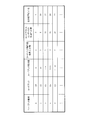
- FIG. 1 is a diagram showing an example of a list of codebooks (or referred to as codebooks) in multi-rate lattice vector quantization for subvectors (see, for example, Patent Document 1 or Non-Patent Document 1).
- the quantization parameter in split multirate lattice vector quantization includes information (eg, "codebook indicator”) or code that identifies the codebook used for quantization, as shown in FIG.
- Information that identifies a selected code vector among a plurality of code vectors contained in the codebook (referred to as a book index) (for example, referred to as a "code vector index”) is included. good.
- one subvector (SV) can be coded (or quantized) by 1, 10, 15, 20. , 25, ..., 5n bits (n is an integer greater than or equal to 2) can be used.
- 1, 2, 3, 4, 5, ..., N bits are codes. It may be used as a book reading.
- the ratio of the number of bits allocated for coding the codebook instruction value to the total number of bits used for coding using each codebook may be 1/5.
- the codebook Q0 may include one vector (for example, a zero vector).
- a zero vector means, for example, that the quantization value of the vector is zero. Therefore, in the codebook Q0, the code vector index does not have to be specified, and the number of bits used for the code vector index may be 0.
- the encoder may collectively encode a plurality of subvectors (for example, eight SVs in Non-Patent Document 1) using the codebook shown in FIG.
- the number of bits that can be used for coding a plurality of subvectors (for example, referred to as "total number of bits") may be known between the coding device and the decoding device (decoder).
- Patent Document 1 proposes, as an example, a method of reducing bits in split multi-rate lattice vector quantization for eight SVs. For example, based on the number of bits used for 7 SVs out of 8 SVs, the codebook indication value (codebook index) used for the remaining 1 SV is estimated according to the following equation (1). (See, for example, Patent Document 1).
- the difference from the number of bits of the value is quantized (or encoded), and the difference information is transmitted to the decoding device.
- the information amount (for example, the number of bits) of the above-mentioned difference information is smaller than the codebook indicated value, and the number of coding bits can be reduced. ..
- Patent Document 1 there is a case where the difference information (in other words, the object to be encoded) becomes a negative number (for example, -1), and the quantization level or the code corresponding to the negative number is used. Alternatively, the complexity of quantization) may increase.
- codebook Q0 eg. codebook indication "0”
- codebook Q2 under special conditions (eg, codebook indication "1"). May not reduce the number of coded bits.
- the special case may be, for example, a case in which there are no bits that are not used for coding among the total number of bits that can be used for coding, and all the bits are used for coding.
- the trailing “0” also referred to as a stop bit
- the codebook instruction value of the codebook Q2 may be "1" (1 bit) in which "0" is omitted from "10".
- the coding bit is generated when the number of bits used for coding becomes 0.
- the number may not be reduced.
- the SV in which the number of bits used for encoding is 0 is likely to be, for example, a high-frequency SV among a plurality of SVs (for example, the 6th, 7th, or 8th SV among 8 SVs). ..
- the coding in other words, in other words, the coding of the codebook indication value of the multi-rate lattice vector quantization (LVQ: Lattice VQ) applied to the split vector quantization (for example, SVQ: Split VQ) is performed.
- LVQ Lattice VQ
- SVQ Split VQ
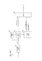
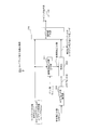
- FIG. 2 is a block diagram showing a configuration example of the coding device 100 according to the embodiment of the present disclosure.
- the coding device 100 shown in FIG. 1 includes, for example, a time-frequency conversion unit 101, a psychoacoustic model analysis unit 102, and a split multi-rate lattice vector quantization (VQ) unit 103 (for example, corresponding to a quantization circuit).
- VQ lattice vector quantization
- a codebook instruction value conversion unit 104 for example, corresponding to a control circuit
- a multiplexing unit 105 may be provided.
- the time-frequency transform unit 101 uses a time-frequency transform method such as a discrete Fourier transform (DFT) or a modified discrete cosine transform (MDCT) to input a signal S (n) in the time domain. May be transformed into an input signal (or spectral coefficient) S (f) in the frequency domain.
- the time-frequency conversion unit 101 may output, for example, the input signal S (f) in the frequency domain to the psychoacoustic model analysis unit 102 and the split multi-rate grid VQ unit 103.
- the psychoacoustic model analysis unit 102 may, for example, perform psychoacoustic model analysis on the input signal S (f) in the frequency domain input from the time-frequency conversion unit 101 and acquire a masking curve.
- the psychoacoustic model analysis unit 102 may output, for example, the acquired information on the masking curve to the split multi-rate grid VQ unit 103.
- the split multi-rate grid VQ unit 103 may perform split multi-rate grid quantization on the input signal S (f) in the frequency domain input from the time-frequency conversion unit 101, for example.
- the split multi-rate grid VQ unit 103 divides the input signal S (f) into a plurality of subvectors (SVs) and quantizes each of the plurality of subvectors to indicate a codebook instruction value indicating a codebook and a codebook instruction value.
- Quantization parameters may be generated that include a code vector index indicating any of the plurality of code vectors contained in the codebook.
- the split multi-rate grid VQ unit 103 may apply the split multi-rate grid VQ to the input signal S (f) in the frequency domain according to the information regarding the masking curve input from the psychoacoustic model analysis unit 102. ..
- the quantization noise in the split multi-rate grid VQ can be inaudible.
- the split multi-rate grid VQ unit 103 may output, for example, the global gain and the code vector index among the quantization parameters obtained by the quantization to the multiplexing unit 105. Further, the split multi-rate grid VQ unit 103 may output, for example, information regarding the codebook instruction value and the code vector index among the quantization parameters to the codebook instruction value conversion unit 104. Further, the split multi-rate grid VQ unit 103 may output, for example, information on the number of bits (for example, Bits available ) that can be used for encoding the input signal S (f) to the codebook instruction value conversion unit 104.
- the codebook instruction value conversion unit 104 may convert the codebook instruction value coding information (or a coded code) based on the information input from the split multi-rate grid VQ unit 103, for example.
- the codebook instruction value conversion unit 104 may perform the following steps 1 to 3 based on each codebook instruction value of a plurality of subvectors input from the split multi-rate grid VQ unit 103.
- the codebook instruction value conversion unit 104 may, for example, among a plurality of (for example, N) codebook instruction values, other subvectors (for example, N-1 subvectors) different from the subvectors at predetermined positions. ) Codebook indication value is set to a code (or a coded code). Then, the codebook instruction value conversion unit 104 may calculate the sum of the number of bits used for the codebook instruction value and the number of bits used for the code vector index in, for example, N-1 subvectors.
- the codebook instruction value conversion unit 104 may calculate, for example, the number of bits that can be used for the codebook instruction value of the subvector at a predetermined position. For example, the codebook instruction value conversion unit 104 encodes N-1 subvectors calculated in (step 1) from the total number of bits (Bits available ) that can be used for encoding the input signal S (f). By subtracting the sum of the number of bits used in, the number of bits that can be used to encode the codebook instruction value of the subvector at the predetermined position may be calculated.
- the codebook instruction value conversion unit 104 is, for example, the number of bits that can be used for coding the subvector at the predetermined position calculated in (step 2) but is not used for coding (for example, the number of bits).
- the number of unused bits may be encoded by calculating (referred to as the number of unused bits).
- the codebook instruction value conversion unit 104 uses the number of usable bits calculated in (step 2) for the number of bits used for the codebook instruction value of the subvector at a predetermined position and the code vector index.
- the number of unused bits may be calculated by subtracting the sum of the number of bits to be used.
- the codebook instruction value conversion unit 104 outputs, for example, the codebook instruction value (encoding code) obtained by (step 1) to (step 3) and the unused bit number encoding code to the multiplexing unit 105. It's okay.
- the multiplexing unit 105 includes a global gain and a code vector index input from the split multi-rate lattice VQ unit 103, a codebook indicated value (encoded code) input from the codebook instruction value conversion unit 104, and the number of unused bits.
- the coded code may be multiplexed and the multiplexed bit stream information may be transmitted to the decoding device 200.
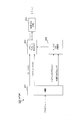
- FIG. 3 is a block diagram showing a configuration example of the codebook instruction value conversion unit 104.
- the codebook instruction value conversion unit 104 shown in FIG. 3 is, for example, a codebook instruction value separation unit 121, a usable bit number calculation unit 122, an unused bit number calculation unit 123, and an unused bit number coding unit 124. And may be prepared.
- the codebook instruction value separation unit 121 outputs the codebook instruction value cbvi (i ⁇ Pfix) of N-1 subvectors different from the positions specified in advance to the usable bit number calculation unit 122, and also outputs the codebook instruction value cbvi (i ⁇ Pfix) to the usable bit number calculation unit 122. It may be output to the multiplexing unit 105 as a codebook instruction value (encoding code) (corresponding to step 1 above).
- the usable bit number calculation unit 122 may calculate, for example, the number of bits that can be used for coding the subvector at the position specified in advance (corresponding to step 2 above). For example, the usable bit number calculation unit 122 calculates N-1 subvectors using N-1 codebook indication values (cbvi (i ⁇ Pfix)) from the input bit number Bits available. The number of bits that can be used to encode the subvector at a pre-specified position may be calculated by subtracting the number of bits used to encode the. The usable bit number calculation unit 122 may output the calculated usable bit number to the unused bit number calculation unit 123 and the unused bit number coding unit 124.
- N-1 codebook indication values cbvi (i ⁇ Pfix)
- the usable bit number calculation unit 122 may calculate the usable bit number cb'fix according to the following equation (2).
- the usable bit number calculation unit 122 uses, for example, the number of bits used for encoding N-1 subvectors (for example, ⁇ Bits ) from the total number of bits Bits available, as shown in the equation (2). By subtracting cbvi (i ⁇ Pfix)), the number of bits cb'fix that can be used to encode the subvector at the pre-specified position is calculated.
- the unused bit number calculation unit 123 may calculate the number of unused bits that are not used for coding the input signal S (f) (corresponding to step 3 above).
- the unused bit number calculation unit 123 can be used in advance based on the number of used bits (actual value cbfix) of the codebook instruction value of the subvector at the position specified in advance, which is input from the codebook instruction value separation unit 121.
- the number of bits used to encode the subvector at the specified position eg, the number of bits used to encode the codebook indication and the code vector index
- the unused bit number calculation unit 123 subtracts the number of bits used for encoding the subvector at the position specified in advance from the usable bit number input from the usable bit number calculation unit 122, for example. Therefore, the number of unused bits may be calculated.
- the unused bit number calculation unit 123 may output, for example, information regarding the calculated unused bit number to the unused bit number coding unit 124.
- the unused bit number coding unit 124 encodes the unused bit number input from the unused bit number calculation unit 123, for example, to generate an unused bit number coding code (or is referred to as coding information). You can do it.
- the unused bit number coding unit 124 is based on the association (for example, may be represented by a table) between the unused bit number and the unused bit number coding code (or the code) shown in FIG. ,
- the unused bit number information coding code may be generated from the unused bit number.
- the unused bit number coding unit 124 may output the unused bit number coding code to the multiplexing unit 105, for example.
- the number of unused bits is an integer of 0 or more.
- the number of candidates for the number of unused bits assigned to one code is five.
- the same code is assigned to five integers out of the number of unused bits. For example, as shown in FIG. 1, when the number of bits used in the codebook instruction value is 2 or more, the number of bits used in the codebook instruction value and the number of bits used in the code vector index are 1: 4. This is because the total number of bits used for encoding the combined codebook instruction value and the code vector index changes in units of 5.
- the unused bit number coding unit 124 may modify the codeword of the maximum unused bit number by using, for example, the number of usable bits input from the usable bit number calculation unit 122. For example, if the number of available bits is 23, the maximum number of unused bits that can be taken is 22 (for example, when Codebook Q0 is used), and in the example of FIG. 4, the codeword is 11110. (5 bits). The unused bit number coding unit 124 may, for example, change (or modify) this codeword 11110 to 1111 (4 bits).
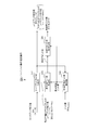
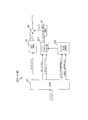
- FIG. 5 is a block diagram showing a configuration example of the decoding device 200 according to the embodiment of the present disclosure.
- the decoding device 200 shown in FIG. 5 includes, for example, a separation unit 201, a codebook instruction value inverse conversion unit 202 (for example, corresponding to a control circuit), and a split multi-rate lattice inverse quantization (inverse VQ) unit 203 (for example,). It may be provided with (corresponding to an inverse quantization circuit) and a frequency-time conversion unit 204.
- the bit stream transmitted from the coding device 100 is input to the separation unit 201.
- the separation unit 201 may separate, for example, the global gain, the code vector index, the codebook instruction value (encoding code), and the unused bit number information encoding code from the input bit stream. For example, the separation unit 201 outputs the global gain and the code vector index to the split multi-rate grid inverse VQ unit 203, and outputs the codebook instruction value (encoded code) and the unused bit number information coding code to the codebook instruction value inverse. It may be output to the conversion unit 202.
- the codebook instruction value inverse conversion unit 202 is based on the codebook instruction value (encoding code) and the unused bit number information encoding code input from the separation unit 201, and the following steps 4 to 7 are performed. Processing may be performed.
- the codebook instruction value inverse conversion unit 202 may decode the unused bit number based on the unused bit number information coding code, for example.
- Step 6 The codebook instruction value inverse conversion unit 202 is specified in advance based on, for example, the number of coded bits of the plurality of subvectors calculated in (step 4) and the number of unused bits decoded in (step 5). The number of coding bits of the subvector at the position may be calculated.
- the codebook instruction value inverse conversion unit 202 indicates, for example, the codebook instruction of the subvector of the predetermined position based on the number of coding bits of the subvector of the predetermined position calculated in (step 6). The value may be calculated (or decoded).
- the codebook instruction value inverse conversion unit 202 may output the codebook instruction value obtained by (step 4) to (step 7) to the split multi-rate grid inverse VQ unit 203, for example.
- the split multi-rate grid inverse VQ unit 203 is based on, for example, the global gain and code vector index input from the separation unit 201 and the output codebook instruction value input from the codebook instruction value inverse conversion unit 202.
- the split multi-rate lattice inverse VQ is performed to obtain the decoding signals S to (f) in the frequency domain.
- the split multi-rate grid inverse VQ unit 203 may output the decoding signals S to (f) in the frequency domain to the frequency-time conversion unit 204.
- the frequency-time transform unit 204 uses a frequency-time transform method such as an inverse discrete Fourier transform (IDFT) or an inverse modified discrete cosine transform (IMDCT) to reverse the split multirate grid.
- the frequency domain signal S ⁇ (f) output from the VQ unit 203 may be converted into the time domain signal S ⁇ (n).
- FIG. 6 is a block diagram showing a configuration example of the codebook instruction value inverse conversion unit 202.
- the codebook instruction value inverse conversion unit 202 shown in FIG. 6 includes, for example, a usable bit number calculation unit 221, an unused bit number decoding unit 222, a restoration unit 223, and a codebook instruction value generation unit 224. It's okay.
- the codebook instruction value (encoding code) output from the separation unit 201 may be input to the usable bit number calculation unit 221 and the codebook instruction value generation unit 224. Further, for example, the unused bit number coding code output from the separation unit 201 may be input to the unused bit number decoding unit 222.
- the usable bit number calculation unit 221 may calculate, for example, the number of bits that can be used for coding the subvector at the position specified in advance. For example, the usable bit number calculation unit 221 calculates the number of bits used for encoding the N-1 subvector using the N-1 codebook indicated value (cbvi (i ⁇ Pfix)). (Corresponding to step 4 above), the number of bits to be input Bits available is subtracted from the number of bits used to encode N-1 subvectors, thereby encoding the subvectors at pre-specified positions. The number of bits that can be used for cb'fix may be calculated. The usable bit number calculation unit 221 may output the calculated usable bit number to the restoration unit 223.
- the unused bit number decoding unit 222 may decode the unused bit number coding code input from the separation unit 201, for example. For example, the unused bit number decoding unit 222 uses the unused bit number coding code to the unused bit based on the association between the unused bit number and the unused bit number coding code (for example, the code) shown in FIG. The number may be determined (corresponding to step 5 above). The unused bit number decoding unit 222 may output, for example, information regarding the determined unused bit number to the restoration unit 223.
- the restoration unit 223 is, for example, at a position specified in advance based on the number of usable bits input from the usable bit number calculation unit 221 and the unused bit number input from the unused bit number decoding unit 222.
- the codebook reading of the subvector may be determined (or restored).
- the restoration unit 223 subtracts the number of unused bits from the number of available bits to use the number of bits used for encoding the subvector at the position specified in advance (for example, the total used bits shown in FIG. 1). Number) may be calculated.
- the restoration unit 223 calculates the number of bits of the codebook instruction value based on the calculated number of bits (for example, the total number of bits used), and generates a codebook instruction value encoding code indicating the codebook instruction value. It may be output to the unit 224 (corresponding to step 6 and step 7 above).
- FIG. 7 is a diagram showing an example of the input signal S (f) in the frequency domain.
- the input signal S (f) may be divided into eight subvectors v1 to v8.
- FIG. 8 is a diagram showing an example of a codebook instruction value (or codebook) for each of the subvectors v1 to v8 obtained by split multi-rate grid quantization.
- the codebook instruction value separation unit 121 does not, for example, set the codebook instruction value of the subvector v8 (for example, 5 bits of “11110”). Output to the used bit number calculation unit 123. Further, the codebook instruction value separation unit 121 is, for example, a codebook instruction value of subvectors v1 to v7 different from the subvector v8 (for example, “10”, “10”, “110”, “110”, “1110”. , "1110", "11110”) may be output to the multiplexing unit 105 as a code code.
- the usable bit number calculation unit 122 may calculate, for example, the number of bits that can be used for coding the subvector v8.
- the total number of bits that can be used in the transmission unit of the input signal (Bits available in the equation (2)) is 144 bits.
- the unused bit number coding unit 124 has, for example, the unused bit number is 4 bits, the unused bit number coding code “0” (1 bit) is generated based on the association shown in FIG. good.
- the codebook instruction values (coding codes) “10”, “10”, “110”, “110”, “1110”, and “respectively of the subvectors v1 to v7 generated in this way) are used.
- 1110 ”,“ 11110 ”, and the unused bit number coding code“ 0 ” are multiplexed in the multiplexing unit 105 and transmitted to the decoding device 200.
- the codebook number applied to the subvector v8 is 5 (Q5), and the number of bits used when encoding the codebook instruction value itself of the codebook Q5. Is 5 bits.
- the number of unused bits transmitted in place of the codebook instruction value for the subvector v8 is 1 bit as described above. Therefore, in the example shown in FIG. 7, the number of unused bits is reduced by 4 bits as compared with the case where the codebook instruction value itself of the subvector v8 is encoded and notified by the notification of the coding code. can. Further, in the present embodiment, even if the coding bits are reduced, the information about the codebook is not lost, so that the codebook instruction value can be restored in the decoding device 200.
- the coding device 100 and the decoding device 200 may use, for example, the number of bits that can be used for coding a subvector in vector quantization (for example, a split multirate lattice VQ) and the quantization parameter of the subvector (for example,). , Codebook instruction value and code vector)
- the number of unused bits based on the difference from the number of bits is used to control the coding or decoding of the codebook instruction value for the subvector.
- the coding device 100 converts the codebook instruction value used for coding a specific subvector in the spectrum of the input signal divided into a plurality of subvectors into information regarding the number of unused bits.
- the decoding device 200 converts the information regarding the number of unused bits into the information regarding the codebook instruction value by using the code code of the number of unused bits transmitted from the coding device 100.
- This transformation improves the efficiency of coding the codebook indication (or codebook index) of one identified SV, for example in lattice vector quantization (LVQ) used for split vector quantization (SVQ).
- LVQ lattice vector quantization
- SVQ split vector quantization
- the number of bits used for the codebook instruction value used for coding a specific subvector can be reduced, and the bit rate can be reduced.
- the difference information to be encoded can be -1.
- the codebook instruction value estimated in Patent Document 1 is 0 (Q0), while the actual codebook instruction value is 1 ().
- Q1 the codebook instruction value estimated in Patent Document 1
- This can increase the complexity of the coding process, such as setting the quantization level corresponding to -1 (negative number) or the association including the code.
- the number of unused bits in the number of bits including both the codebook instruction value and the code vector index is encoded, so that the minimum number of unused bits to be encoded is minimized. Since the value is 0 and it is not necessary to consider the coding of negative numbers, the coding process can be simplified.
- transform coding is applied to a coding method
- the coding method is not limited to transform coding.
- one embodiment of the present disclosure may be applied to coding in which each of a plurality of subvectors obtained by dividing a signal (spectrum) in the frequency domain is quantized.
- the total number of bits that can be used for coding is input to the usable bit number calculation units 122 and 221.
- the total number of usable bits may not be information input from the outside of the encoder (for example, the encoding device 100) or the decoder (for example, the decoding device 200), but may be information held inside the encoder or the decoder.
- the total number of usable bits may be, for example, a predetermined fixed value. Alternatively, a predetermined fixed value may be used as the initial value, and a value obtained by adding the number of unused bits to the initial value may be input as the total number of usable bits at the time of the subsequent split multi-rate grid VQ.
- the split multirate grid VQ may be applied to CELP and hierarchical coding of transform coding.
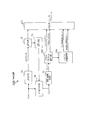
- FIG. 9 is a block diagram showing a configuration example of a coding device 100a when the split multi-rate grid VQ is applied to CELP and hierarchical coding of transform coding.
- FIG. 10 is a block diagram showing a configuration example of the decoding device 200a when the split multi-rate grid VQ is applied to CELP and hierarchical coding of transform coding.
- the CELP coding unit 51 performs CELP coding on the signal S (n) in the time domain, and outputs the CELP parameters to the CELP local decoding unit 52 and the multiplexing unit 105, for example. You may output it.
- the CELP coding method is, for example, a coding method that utilizes the predictable property of a signal in the time domain.
- the CELP local decoding unit 52 decodes the CELP parameter input from the CELP coding unit 51, for example, and generates a composite signal S syn (n).
- the adder 53 generates a prediction error signal S e (n) by , for example, subtracting the combined signal S syn (n) from the input signal S (n).
- the time-frequency conversion unit 54 converts the time-domain coding error signal S e (n) into the frequency-domain coding error signal S e (f) by a time-frequency conversion method such as DFT or MDCT.
- the coding error signal S e (f) in the frequency domain may be quantized by the split multi-rate lattice VQ unit 103 and the codebook instruction value conversion unit 104.
- the codebook instruction value (coding code) of a specific subvector may be transmitted to the decoding device 200a.
- the separation unit 201 separates the bit stream transmitted from the coding device 100a into a CELP parameter and a quantization parameter, outputs the CELP parameter to the CELP decoding unit 64, and performs a quantum.
- the global gain and the code vector index are output to the split multi-rate lattice inverse VQ unit 203, and the code-book instruction value (coding code) and the unused bit number coding code among the quantization parameters are code-book-instructed. It is output to the value inverse conversion unit 202.
- the codebook instruction value inverse conversion unit 202 determines the coding error signal S e (f) based on the codebook instruction value (coding code) and the unused bit number coding code.
- the codebook instruction value for the subvector at a specific position is determined, and the information about the codebook instruction value of N subvectors is output to the split multi-rate lattice inverse VQ unit 203.
- the split multi-rate lattice inverse VQ section 203 decodes (or inversely quantizes) the coding error signal S e ⁇ (f) in the frequency domain based on, for example, the global gain, the codebook reading, and the code vector index. )do.
- Frequency - time conversion unit 63 is, for example, coded error signal S e ⁇ decoded frequency domain (f), the frequency such IDFT or IMDCT - by time conversion scheme, coding the error signal S e ⁇ in the time domain ( Convert to n).
- the CELP decoding unit 64 decodes the CELP parameter, for example, to obtain a synthetic signal S syn (n).
- the adder 65 for example, adds the coding error signal S e ⁇ (n) and the combined signal S syn (n) to obtain the signal S ⁇ (n) in the time domain.
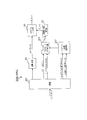
- FIG. 11 is a block diagram showing a configuration example of the coding device 100b in this case
- FIG. 12 is a block diagram showing a configuration example of the decoding device 200b.
- the LPC (Linear Predictive Coding) analysis unit 71 performs LPC analysis on the signal S (n) in the time domain and outputs the LPC parameter to the quantization unit 72.
- LPC analysis is, for example, a method that utilizes the predictable properties of time domain signals.
- the quantization unit 72 quantizes the LPC parameter input from the LPC analysis unit 71, for example, and outputs the quantization parameter (for example, the quantization index) to the inverse quantization unit 73 and the multiplexing unit 105.
- the dequantization unit 73 dequantizes the quantization index input from the quantization unit 72 and restores the LPC parameter.
- the LPC inverse filter unit 74 applies, for example, LPC inverse filtering using the restored LPC parameters input from the inverse quantization unit 73 to the input signal S (n), thereby performing a residual in the time domain. Obtain the signal S r (n).
- the time-frequency conversion unit 75 converts the residual signal S r (n) in the time domain into the residual signal S r (f) in the frequency domain by a time-frequency conversion method such as DFT or MDCT.
- the residual signal S r (f) in the frequency domain may be quantized by the split multi-rate grid VQ unit 103 and the codebook indicated value conversion unit 104.
- the coding apparatus 100b encodes an unused bit number instead of the codebook instruction value (coding code) of a specific subvector among a plurality of subvectors obtained by dividing the residual signal S r (f).
- the code may be transmitted to the decoding device 200b.
- the separation unit 201 separates the bit stream transmitted from the coding device 100b into a quantization index and a quantization parameter, and outputs the quantization index to the inverse quantization unit 84. Then, among the quantization parameters, the global gain and the code vector index are output to the split multi-rate lattice inverse VQ unit 203, and the codebook instruction value (coding code) and the unused bit number coding code among the quantization parameters are output. It is output to the codebook instruction value inverse conversion unit 202.
- the codebook instruction value inverse conversion unit 202 specifies the residual signal S r (f) based on the codebook instruction value (encoding code) and the unused bit number encoding code, for example, as described above.
- the codebook instruction value for the subvector at the position of is determined, and the information about the codebook instruction value of N subvectors is output to the split multi-rate lattice inverse VQ unit 203.
- the split multi-rate lattice inverse VQ section 203 decodes (or inversely quantizes) the residual signal S r ⁇ (f) in the frequency domain based on, for example, the global gain, the codebook reading, and the code vector index. do.
- the frequency-time conversion unit 83 uses, for example, the decoded frequency domain residual signal S r ⁇ (f) by a frequency-time conversion method such as IDFT or IMDCT to obtain the time domain residual signal S r ⁇ (n). Convert to.
- the dequantization unit 84 dequantizes the quantization index and restores the LPC parameter.
- the LPC synthesis filter unit 85 applies, for example, LPC synthesis filtering using the restored LPC parameters to the residual signal S r ⁇ (n) in the time domain, and the signal S ⁇ (n) in the time domain. To get.
- the LPC synthesis filter processing is performed in the time domain in the present embodiment, it may be performed in the frequency domain.
- An example of such TCX coding is the EVS codec MDCT based TCX.
- the split multi-rate grid VQ may be applied to, for example, an acoustic sound coding process and a decoding process such as the EVS (Enhanced Voice Services) codec described in Non-Patent Document 1.
- EVS Enhanced Voice Services
- the split multi-rate lattice VQ may be applied to the algebraic vector quantizer (AVQ: Algebraic Vector Quantizer) of Non-Patent Document 1.
- AVQ Algebraic Vector Quantizer
- AVQ is applied to various coding modes.
- the coded frame is classified as a harmonic signal in the 32 kbit / s GC (Generic Coding) mode
- the codebook indicated code number in the split multirate grid VQ is the higher frequency subvector (eg, for example).
- the subvector v8) is likely to increase.
- the GC mode coding for the harmonic signal is likely to be performed at the rising edge of the vowel, and the higher the frequency band, the worse the expressiveness of harmonics in the adaptive codebook (or adaptive codebook).
- the reason for this is that the higher the frequency, the more likely it is that the harmonics will shift, and the larger the coding error of the adaptive codebook will be. Therefore, in the coding of a signal in the frequency domain (for example, the spectrum of a prediction error or a residual signal), the higher the subvector, the higher the energy of the signal and the larger the number of bits used for quantization. Book is easy to select.
- the subvector v8 may be set to the subvector at a specific position.
- the subvector having the highest frequency among the plurality of subvectors constituting the input signal is the subvector.
- the vector may be set to one subvector that encodes the number of unused bits.
- the split multi-rate grid VQ may be applied to the signal in the time domain depending on the coded bit rate of EVS. Even in this case, it is effective to set the last subvector (in other words, the last subvector in time) at the predetermined subvector position. This is because it has been experimentally confirmed that in such a case, the number of bits used for encoding the unused bits tends to be less than the number of bits used for encoding the codebook instruction value. Is. That is, in a frame classified into the GC mode, the number of bits remaining unused at the time of quantization of the last subvector is often small, so that the coding efficiency is higher when the number of unused bits is encoded. Cheap.
- ⁇ Method 1> For example, if the number of bits used to encode a subvector at a particular position (eg, subvector v8) is low (eg, Codebook Q0 or Q2) and the number of unused bits is high (eg, 15 bits). In the above case), the number of bits used to encode the number of unused bits may be larger than the number of bits used to encode the codebook instruction value itself.
- the codebook that can be used for the subvector at a specific position is a codebook.
- Q0 codebook indicated value is 1 bit of "0”
- special case codebook Q2 codebook indicated value is 1 bit of "1"
- the codebook instruction value is represented by 1 bit (in other words, the minimum value), and therefore, it is also encoded by the method according to the embodiment of the present disclosure. The number of bits cannot be reduced.
- the coding apparatus 100 when the number of bits that can be used for the subvector at a specific position is equal to or less than a threshold value (for example, 9 bits or less), the coding apparatus 100 according to an embodiment of the present disclosure (for example, unused bits).
- the codebook instruction value of the subvector at a specific position may be determined as it is as a code code (or coding information) without applying the method of encoding a number).
- the coding apparatus 100 encodes a code code that encodes the number of unused bits. It may be determined as the coding information.
- the method 1 it is possible to suppress an increase in the number of coding bits and improve the efficiency of coding regardless of the number of bits that can be used for the subvector at a specific position.
- the number of bits that can be used for the subvector at a specific position can be calculated by the decoding device 200 from other parameters (for example, the total number of bits and the codebook indicated value of the other subvector). Therefore, it is not necessary to provide signaling for switching the coding method according to the method 1 (for example, additional information for notifying the switching).
- the codebook that can be used in the subvector at a particular position is codebook Q0 (eg, total). Number of bits used: 1 bit) or Codebook Q2 (for example, total number of bits used: 10 bits).
- the codebook Q0 for example, the total number of used bits: 1 bit
- the number of unused bits is 10 to 12 bits. Therefore, in the example shown in FIG. 4, the number of unused bits is used.
- the number of coding bits of is 3 bits. Therefore, the number of bits is increased by 2 bits as compared with the case where the codebook instruction value is encoded as it is (for example, 1 bit).
- the function "a% b" is a function that returns the remainder of b with respect to a (for example, it is also called a modulo operation).
- the coding apparatus 100 subtracts a remainder of 5 (in other words, the number of bits that are clearly unused) from the number of usable bits (cb'fix) with respect to the number of usable bits, and uses the subtraction result to obtain a result.
- the number of unused bits may be calculated.
- the coding device 100 may set, for example, 10 bits of the subtraction result to the usable bits.
- the codebook Q0 (1 bit) is used for 10 usable bits
- the number of unused bits is 9 bits. Therefore, in the example shown in FIG. 4, the number of unused bits is 9. It is encoded by a 2-bit unused bit number coding code.
- the number of bits used for encoding the number of unused bits is the case where the remainder of 5 is not subtracted from the number of available bits. It is reduced compared to the number of bits used to encode the number of unused bits (eg, 3 bits). In other words, for example, when subtracting the remainder of 5 from the number of available bits, the increase in the number of bits should be suppressed to 1 bit as compared with the case where the codebook instruction value is encoded as it is (for example, 1 bit). Can be done.
- ⁇ Method 3> For example, when the number of usable bits (cb'fix) is 10 bits, the number of unused bits does not exceed 10 bits (in other words, it is 9 bits or less), so the number of unused bits in the example shown in FIG. 4 The "0" of the code "10" corresponding to 5 to 9 may be omitted. In other words, in this case, it suffices to distinguish between 0 to 4 (reference numeral “0”) and 5 to 9 (reference numeral “1”) in the number of unused bits. By such coding, the number of bits used for coding the number of unused bits can be further reduced by one bit, and the increase in the number of bits can be suppressed.
- the coding apparatus 100 does not switch to the method of setting the codebook instruction value as it is in the code code as described in ⁇ Method 1> even when the number of usable bits is 9 bits or less. May be good.
- ⁇ Method 4> For example, when the number of usable bits (cb'fix) is 8 bits or less, in the example shown in FIG. 1, there is no possibility that the codebook indicated value becomes a value other than “0” (Q0). In this case, the decoding device 200 can specify the codebook instruction value Q0 even if the information regarding the codebook instruction value is not transmitted.
- the codebook of the codebook Q0 Coding processing and decoding processing without transmission / reception of information regarding the indicated value may be performed. This makes it possible to reduce the coded information by 1 bit.
- ⁇ Method 5> when the number of usable bits (cb'fix) is 14 bits, in the example shown in FIG. 1, the codebooks that can be used for the subvector at a specific position are the codebooks Q0, Q2, and the codebook of the special case. Q3.
- the codebook indication value can be represented by "11" (2 bits) instead of "110", and the number of bits used in the code vector (12 bits). It can be encoded with 14 bits in total.
- the number of usable bits when the number of usable bits is 13 bits or less, it is possible to suppress an increase in the number of coded bits of 2 bits or more based on at least one of ⁇ Method 1> to ⁇ Method 4> described above.
- the number of usable bits when the number of usable bits is 14 bits or more, the number of encoded bits may be increased or decreased depending on the number of unused bits.
- the unused bits occupy most of the usable bits (for example, the number of unused bits). Is above the threshold) is assumed to be rare. Therefore, for example, the number of unused bits less than the threshold value is likely to be encoded, and the reduction in the number of bits can be achieved on average. On the other hand, in rare cases, the number of unused bits may increase and the number of coded bits may increase by 2 bits or more. Therefore, for example, the coding method may be switched based on the following method.
- whether or not the input signal is close to zero can be determined based on the gain information (or gain information) multiplied by the energy of the adaptive codebook vector or the excitation signal encoded by the AVQ. Is.
- the coding apparatus 100 for example, when the energy of the adaptive codebook vector (or code vector) is less than the threshold value (for example, 10), or the gain multiplied by the excitation signal encoded by AVQ is the threshold value (for example). For example, if it is less than 1.0), the codebook reading of the subvector at a specific position is used without applying the method according to the embodiment of the present disclosure (for example, the method of encoding the number of unused bits).
- the code code may be determined as it is.
- the code code in which the number of unused bits is encoded may be determined as the coding information.
- the coding apparatus 100 may switch the coding method based on, for example, a combination of the energy of the adaptive codebook vector and the gain multiplied by the excitation signal encoded by the AVQ. At this time, the coding apparatus 100 may, for example, weight the energy of the adaptive codebook vector and the gain multiplied by the excitation signal when determining the switching of the coding method.
- the gain multiplied by the excitation signal encoded by the AVQ is not fixed until the AVQ coding is completed in the coded target frame, for example, the gain information in the past frame may be referred to in time. ..
- Method 5 as an example, a method of switching the coding method based on the energy or gain information of the adaptive codebook vector has been described, but the method is not limited to this, and other parameters related to the increase / decrease in the number of unused bits are described.
- the coding method may be switched based on.
- the coding method may be switched based on the comparison between the number of unused bits and the threshold value.
- the upper limit of the number of unused bits is the number of usable bits, there is no need for a code code (or code) that exceeds the number of usable bits.
- the code of the upper limit of the number of unused bits the zero at the end of the code (for example, the stop bit) may not be present.
- the decoding device 200 can specify the number of unused bits.
- the example shown in FIG. 13 may be applied instead of the example shown in FIG. 4 for the association between the number of unused bits and the code.
- the reference numeral shown in FIG. 13 corresponds to, for example, a Huffman code.
- the number of bits of the code “111” is one bit less when the number of unused bits is 15 to 19 bits as compared with FIG.
- the code code (or coding information) in which the number of unused bits is encoded may be represented by a Huffman code having the number of usable bits as the upper limit of the number of unused bits.
- the coding apparatus 100 may encode the unused bits by using a Huffman code according to the upper limit of the unused bits. As a result, the number of bits used for coding the codebook instruction value can be reduced by one bit.
- the code assigned to the number of unused bits may be represented by an Unary code.
- the code assigned to the number of unused bits may be represented by an Unary code.
- the code assigned to the number of unused bits may be represented by an Unary code.
- the number of usable bits among the plurality of Unary codes assigned to the number of unused bits.
- the upper limit of the number of unused bits corresponds to Unary.
- the code is 4 bits of "1110".
- the least significant bit “0” of the Unary code “1110” may be truncated to “111”, and the association between the number of unused bits and the code is the same as in the example shown in FIG. As a result, the number of bits used for coding the codebook instruction value can be reduced by one bit.
- the subvector at a specific position has a longer word length (or number of bits) depending on the number of available bits. Codebook readings are easier to select. Also, when a codebook reading with a longer word length is selected, the number of unused bits becomes closer to 0, making it easier to select a code code with a shorter number of unused bits. In method 6, this tendency is used by the encoder 100 to calculate the maximum codebook indication that can be used to encode the subvector based on the number of bits available for the subvector at a particular position.
- the code assigned to the number of unused bits may be represented by a Huffman code or an Unary code (for example, a code obtained by cutting off the LSB of the Unary code assigned to the upper limit of the number of unused bits).
- an Unary code for example, a code obtained by cutting off the LSB of the Unary code assigned to the upper limit of the number of unused bits.
- the number of usable bits is 10 bits or more, there is a high possibility that the surplus bits of 5 will be unused. Therefore, in the method 6, the number of usable bits is 5. It may be a value obtained by subtracting the remainder of.
- the probability that the number of unused bits is 5-9 bits is the highest, and the probability that the number of unused bits is 0-4 bits is the second highest.
- the distribution after 10-14 bits may be the third and subsequent distributions (for example, when the GC mode is selected).
- a method of assigning a code to the number of unused bits in this case for example, a code “0” having an unused bit number of 0-4 bits and a code “10” having an unused bit number of 5-9 bits are used. It may be replaced (for example, FIG. 14).
- the number of bits of the code corresponding to the candidate having a higher probability of occurrence may be smaller.
- the average number of coded bits can be reduced.
- FIG. 14 is an example, and a code having a different number of bits may be assigned according to the probability of occurrence of the number of unused bits. For such allocation, the optimum allocation method may be determined in advance for each coding mode, so that it is not necessary to encode or transmit information regarding the allocation method.
- the code assigned to the number of unused bits shown in FIGS. 4, 13 and 14 is an Unary code having "0" as a stop bit, but is not limited thereto.
- "1" and "0" in the code assigned to the number of unused bits shown in FIGS. 4, 13 and 14 may be interchanged.
- Huffman coding can be applied to the method of coding the codebook instruction value as it is.
- the codebook indicated value of Q4 is 4 bits of “1110”.
- the codebook indicated value of Q4 may be "111" with "0" omitted from "1110". As a result, the number of coding bits of the codebook instruction value can be reduced.
- the codebook list is not limited to the example shown in FIG. 1, and the codebook instruction value and the code value of the code vector index in the codebook and the number of bits used (or the total number of bits used). The number) may be another value.
- the threshold values described in ⁇ Method 1> to ⁇ Method 6> described above may be set according to the codebook list applied to the coding and decoding.
- Each functional block used in the description of the above embodiment is partially or wholly realized as an LSI which is an integrated circuit, and each process described in the above embodiment is partially or wholly. It may be controlled by one LSI or a combination of LSIs.
- the LSI may be composed of individual chips, or may be composed of one chip so as to include a part or all of functional blocks.
- the LSI may include data input and output.
- LSIs may be referred to as ICs, system LSIs, super LSIs, and ultra LSIs depending on the degree of integration.
- the method of making an integrated circuit is not limited to LSI, and may be realized by a dedicated circuit, a general-purpose processor, or a dedicated processor. Further, an FPGA (Field Programmable Gate Array) that can be programmed after the LSI is manufactured, or a reconfigurable processor that can reconfigure the connection and settings of the circuit cells inside the LSI may be used.
- the present disclosure may be realized as digital processing or analog processing. Furthermore, if an integrated circuit technology that replaces an LSI appears due to advances in semiconductor technology or another technology derived from it, it is naturally possible to integrate functional blocks using that technology. The application of biotechnology may be possible.
- the communication device may include a wireless transceiver and a processing / control circuit.
- the wireless transceiver may include a receiver and a transmitter, or them as a function.
- the radio transceiver (transmitter, receiver) may include an RF (Radio Frequency) module and one or more antennas.
- the RF module may include an amplifier, an RF modulator / demodulator, or the like.
- Non-limiting examples of communication devices include telephones (mobile phones, smartphones, etc.), tablets, personal computers (PCs) (laptops, desktops, notebooks, etc.), cameras (digital stills / video cameras, etc.).
- Digital players digital audio / video players, etc.
- wearable devices wearable cameras, smart watches, tracking devices, etc.
- game consoles digital book readers
- telehealth telemedicines remote health Care / medicine prescription
- vehicles with communication functions or mobile transportation automobiles, planes, ships, etc.
- combinations of the above-mentioned various devices can be mentioned.
- Communication devices are not limited to those that are portable or mobile, but are all types of devices, devices, systems that are not portable or fixed, such as smart home devices (home appliances, lighting equipment, smart meters or Includes measuring instruments, control panels, etc.), vending machines, and any other "Things” that can exist on the IoT (Internet of Things) network.
- smart home devices home appliances, lighting equipment, smart meters or Includes measuring instruments, control panels, etc.
- vending machines and any other “Things” that can exist on the IoT (Internet of Things) network.
- Communication includes data communication by a combination of these, in addition to data communication by a cellular system, a wireless LAN system, a communication satellite system, etc.
- the communication device also includes devices such as controllers and sensors that are connected or connected to communication devices that perform the communication functions described in the present disclosure.
- devices such as controllers and sensors that are connected or connected to communication devices that perform the communication functions described in the present disclosure.
- controllers and sensors that generate control and data signals used by communication devices that perform the communication functions of the communication device.
- Communication devices also include infrastructure equipment that communicates with or controls these non-limiting devices, such as base stations, access points, and any other device, device, or system. ..
- the coding apparatus includes a quantization circuit that generates a quantization parameter including a first information regarding a codebook for vector quantization and a second information regarding a code vector included in the codebook. , The second bit with respect to the subvector, using the number of second bits based on the difference between the number of first bits available for coding the subvector in the vector quantization and the number of bits of the quantization parameter of the subvector.
- a control circuit for controlling the coding of information is provided.
- control circuit determines the information in which the second bit number is encoded as the encoded information.
- the information encoded by the second bit number is represented by a Huffman code having the first bit number as the upper limit value of the second bit number.
- the information encoded by the second bit number is represented by an Unary code, and the Unary code corresponding to the upper limit value of the second bit number set based on the first bit number.
- the least significant bit of is deleted.
- the number of bits of the information corresponding to the candidate having a higher probability of occurrence is smaller.
- the control circuit determines the information obtained by encoding the number of the second bits as the coding information, and the number of the first bits is the threshold value.
- the first information is determined to be encoded information.
- the subvector in the Generic Coding (mode) of the Enhanced Voice Services (EVS) codec, the subvector has the highest frequency (or the last in time) of the plurality of subvectors that divide the signal. ) Subvector.
- the control circuit determines the information obtained by encoding the second bit number as the coded information, and determines the coded information of the code vector.
- the first information is determined as the coding information.
- the control circuit determines the information obtained by encoding the second bit number as the encoded information, and when the gain is less than the threshold value. , The first information is determined to be coded information.
- the second bit number is a number obtained by subtracting the number of bits of the quantization parameter of the subvector from the remainder of 5 with respect to the first bit number.
- the decoding apparatus includes the number of first bits that can be used for coding a subvector in vector quantization, the first information regarding the codebook of the subvector, and the code vector included in the codebook.
- a control circuit that controls the decoding of the first information with respect to the subvector using the number of second bits based on the difference from the number of bits of the quantization parameter including the second information regarding the above, and the reverse based on the first information. It is equipped with an inverse quantization circuit that performs vector quantization.
- the coding apparatus In the coding method according to an embodiment of the present disclosure, the coding apparatus generates a quantization parameter including a first information regarding a codebook for vector quantization and a second information regarding a code vector included in the codebook. Then, using the number of second bits based on the difference between the number of first bits that can be used for coding the subvector in the vector quantization and the number of bits of the quantization parameter of the subvector, the said with respect to the subvector. It controls the coding of the first information.
- the decoding apparatus includes the number of first bits that can be used for encoding the subvector in vector quantization, the first information regarding the codebook of the subvector, and the codebook.
- the number of second bits based on the difference from the number of bits of the quantization parameter including the second information regarding the code vector included is used to control the decoding of the first information with respect to the subvector, based on the first information. Perform inverse vector quantization.
- One embodiment of the present disclosure is useful for a coding system or the like.
- CELP coding unit 52 CELP local decoding unit 53,65 adder 64
- CELP decoding unit 71 LPC analysis unit 72 quantization unit 73,84 inverse quantization unit 74
- LPC inverse filter unit 85 LPC synthesis filter unit 100, 100a, 100b code Computer 54,75,101 Time-frequency conversion unit 102
- Psychoacoustic model analysis unit 103 Split multi-rate lattice quantization unit 104
- Codebook instruction value conversion unit 105 Multiplication unit 121 Codebook instruction value separation unit 122,221 Usable bits Number calculation unit 123 Unused bit number calculation unit 124 Unused bit number coding unit 200, 200a, 200b Decoding device 201 Separation unit 202
- Codebook instruction value inverse conversion unit 203 Split multi-rate lattice inverse quantization unit 63, 83, 204 Frequency-time conversion unit 222 Unused bit number Decoding unit 223
- Restoration unit 224 Codebook instruction value generation unit
Landscapes
- Engineering & Computer Science (AREA)
- Physics & Mathematics (AREA)
- Spectroscopy & Molecular Physics (AREA)
- Theoretical Computer Science (AREA)
- Computational Linguistics (AREA)
- Signal Processing (AREA)
- Health & Medical Sciences (AREA)
- Audiology, Speech & Language Pathology (AREA)
- Human Computer Interaction (AREA)
- Acoustics & Sound (AREA)
- Multimedia (AREA)
- Compression, Expansion, Code Conversion, And Decoders (AREA)
Abstract
Description

図2は、本開示の一実施例に係る符号化装置100の構成例を示すブロック図である。図1に示す符号化装置100は、例えば、時間-周波数変換部101と、心理音響モデル分析部102と、スプリットマルチレート格子ベクトル量子化(VQ)部103(例えば、量子化回路に相当)と、コードブック指示値変換部104(例えば、制御回路に相当)と、多重化部105と、を備えてよい。
コードブック指示値変換部104は、例えば、複数(例えば、N個)のコードブック指示値のうち、予め定められた位置のサブベクトルと異なる他のサブベクトル(例えば、N-1個のサブベクトル)のコードブック指示値を符号(又は、符号化コード)に設定する。そして、コードブック指示値変換部104は、例えば、N-1個のサブベクトルにおいて、コードブック指示値の使用ビット数及びコードベクトルインデックスの使用ビット数の総和を算出してよい。
コードブック指示値変換部104は、例えば、予め定められた位置のサブベクトルのコードブック指示値に使用可能なビット数を算出してよい。例えば、コードブック指示値変換部104は、入力信号S(f)の符号化に使用可能なビット総数(Bitsavailable)から、(ステップ1)で算出されたN-1個のサブベクトルの符号化に使われるビット数の総和を減じることにより、予め定められた位置のサブベクトルのコードブック指示値の符号化に使用可能なビット数を算出してもよい。
コードブック指示値変換部104は、例えば、(ステップ2)で算出された、予め定められた位置のサブベクトルの符号化に使用可能なビット数のうち、符号化に使用されないビット数(例えば、未使用ビット数と呼ぶ)を算出して、未使用ビット数を符号化してよい。例えば、コードブック指示値変換部104は、(ステップ2)で算出された使用可能ビット数から、予め定められた位置のサブベクトルのコードブック指示値に使用されるビット数及びコードベクトルインデックスに使用されるビット数の和を減算して、未使用ビット数を算出してよい。

図5は、本開示の一実施例に係る復号装置200の構成例を示すブロック図である。図5に示す復号装置200は、例えば、分離部201と、コードブック指示値逆変換部202(例えば、制御回路に相当)と、スプリットマルチレート格子逆量子化(逆VQ)部203(例えば、逆量子化回路に相当)と、周波数-時間変換部204と、を備えてよい。
コードブック指示値逆変換部202は、例えば、コードブック指示値(符号化コード)に基づいて、予め特定された位置(例えば、i=Pfix)と異なる他のサブベクトルのコードブック指示値を復号する。また、コードブック指示値逆変換部202は、例えば、復号したコードブック指示値に基づいて、複数のサブベクトル(例えば、i≠Pfix)の符号化に使用されるビット数(例えば、コードブック指示値の使用ビット数とコードベクトルの使用ビット数との和)を算出してよい。
コードブック指示値逆変換部202は、例えば、未使用ビット数情報符号化コードに基づいて、未使用ビット数を復号してよい。
コードブック指示値逆変換部202は、例えば、(ステップ4)で算出された複数のサブベクトルの符号化ビット数と、(ステップ5)で復号された未使用ビット数に基づいて、予め特定された位置のサブベクトルの符号化ビット数を算出してよい。
コードブック指示値逆変換部202は、例えば、(ステップ6)で算出された、予め特定された位置のサブベクトルの符号化ビット数に基づいて、予め特定された位置のサブベクトルのコードブック指示値を算出(又は、復号)してよい。
次に、符号化装置100のコードブック指示値変換部104の動作例について説明する。
例えば、本実施の形態に係るスプリットマルチレート格子VQをCELP及び変換符号化の階層的符号化に適用してもよい。図9は、スプリットマルチレート格子VQをCELP及び変換符号化の階層的符号化に適用する場合の符号化装置100aの構成例を示すブロック図である。また、図10は、スプリットマルチレート格子VQをCELP及び変換符号化の階層的符号化に適用する場合の復号装置200aの構成例を示すブロック図である。
例えば、本実施の形態に係るスプリットマルチレート格子VQをTCX符号化(又は、TCXコーデックと呼ぶ)に適用してもよい。図11は、この場合の符号化装置100bの構成例を示すブロック図であり、図12は、復号装置200bの構成例を示すブロック図である。
上述した特定の位置のサブベクトルの一例について説明する。
次に、特定の位置のサブベクトルに対する符号化ビット数を削減する方法の例について説明する。
例えば、特定の位置のサブベクトル(例えば、サブベクトルv8)の符号化に使用されるビット数が少なく(例えば、コードブックQ0又はQ2)、未使用ビット数が多い場合(例えば、15ビットといった閾値以上の場合)には、未使用ビット数の符号化に使用されるビット数の方が、コードブック指示値そのものを符号化する場合よりも多くなる可能性がある。
例えば、使用可能ビット数(cb’fix)が11~13ビットの何れかの場合、特定の位置のサブベクトル(例えば、サブベクトルv8)において使用可能なコードブックは、コードブックQ0(例えば、合計使用ビット数:1ビット)又はコードブックQ2(例えば、合計使用ビット数:10ビット)の何れかである。ここで、例えば、コードブックQ0が使用される場合(例えば、合計使用ビット数:1ビット)、未使用ビット数は、10~12ビットとなるので、図4に示す例では、未使用ビット数の符号化ビット数は3ビットになる。このため、コードブック指示値をそのまま符号化する場合(例えば、1ビット)と比較して、ビット数が2ビット増加する。
例えば、使用可能ビット数(cb’fix)が10ビットの場合、未使用ビット数は10ビット以上にならないので(換言すると、9ビット以下であるので)、図4に示す例において未使用ビット数5~9に対応する符号“10”の“0”は無くてもよい。換言すると、この場合、未使用ビット数が0~4(符号“0”)と、5~9(符号“1”)とが区別されればよい。このような符号化により、未使用ビット数の符号に使用されるビット数をさらに1ビット削減でき、ビット数の増加を抑制できる。
例えば、使用可能ビット数(cb’fix)が8ビット以下の場合、図1に示す例では、コードブック指示値が“0”(Q0)以外の値になる可能性は無い。この場合、復号装置200は、コードブック指示値に関する情報が送信されなくても、コードブック指示値Q0を特定可能である。
例えば、使用可能ビット数(cb’fix)が14ビットの場合、図1に示す例では特定の位置のサブベクトルに使用可能なコードブックは、コードブックQ0、Q2、及び、特殊ケースのコードブックQ3である。特殊ケースのコードブックQ3では、例えば、未使用ビットが無く、コードブック指示値を“110”の代わりに“11”(2ビット)で表すことができ、コードベクトルの使用ビット数(12ビット)と合わせて14ビットで符号化可能である。
未使用ビット数と符号との関連付けは、図4に示す例に限定されない。
52 CELPローカル復号部
53,65 加算器
64 CELP復号部
71 LPC分析部
72 量子化部
73,84 逆量子化部
74 LPC逆フィルタ部
85 LPC合成フィルタ部
100,100a,100b 符号化装置
54,75,101 時間-周波数変換部
102 心理音響モデル分析部
103 スプリットマルチレート格子量子化部
104 コードブック指示値変換部
105 多重化部
121 コードブック指示値分離部
122,221 使用可能ビット数算出部
123 未使用ビット数算出部
124 未使用ビット数符号化部
200,200a,200b 復号装置
201 分離部
202 コードブック指示値逆変換部
203 スプリットマルチレート格子逆量子化部
63,83,204 周波数-時間変換部
222 未使用ビット数復号部
223 復元部
224 コードブック指示値生成部
Claims (13)
- ベクトル量子化のコードブックに関する第1情報、及び、前記コードブックに含まれるコードベクトルに関する第2情報を含む量子化パラメータを生成する量子化回路と、
前記ベクトル量子化においてサブベクトルの符号化に使用可能な第1ビット数と前記サブベクトルの前記量子化パラメータのビット数との差に基づく第2ビット数を用いて、前記サブベクトルに対する前記第1情報の符号化を制御する制御回路と、
を具備する符号化装置。 - 前記制御回路は、前記第2ビット数を符号化した情報を符号化情報に決定する、
請求項1に記載の符号化装置。 - 前記第2ビット数を符号化した情報は、前記第1ビット数を前記第2ビット数の上限値とするハフマン符号によって表される、
請求項2に記載の符号化装置。 - 前記第2ビット数を符号化した情報は、Unary符号によって表され、
前記第1ビット数に基づいて設定される前記第2ビット数の上限値に対応するUnary符号の最下位ビットは削除される、
請求項2に記載の符号化装置。 - 前記第2ビット数の候補それぞれを符号化した情報のうち、発生確率がより高い前記候補に対応する情報のビット数はより少ない、
請求項2に記載の符号化装置。 - 前記制御回路は、
前記第1ビット数が閾値より多い場合、前記第2ビット数を符号化した情報を符号化情報に決定し、
前記第1ビット数が前記閾値以下の場合、前記第1情報を符号化情報に決定する、
請求項1に記載の符号化装置。 - Enhanced Voice Services(EVS)コーデックのGeneric Coding(モード)において、前記ベクトル量子化の対象の信号がharmonic信号である場合、
前記サブベクトルは、前記信号を分割した複数のサブベクトルのうち、最も周波数の高いサブベクトル、又は、時間的に最後のサブベクトルである、
請求項1に記載の符号化装置。 - 前記制御回路は、
前記サブベクトルに対する前記コードベクトルのエネルギが閾値以上の場合、前記第2ビット数を符号化した情報を符号化情報に決定し、
前記コードベクトルのエネルギが前記閾値未満の場合、前記第1情報を符号化情報に決定する、
請求項1に記載の符号化装置。 - 前記制御回路は、
前記サブベクトルに対するゲインが閾値以上の場合、前記第2ビット数を符号化した情報を符号化情報に決定し、
前記ゲインが前記閾値未満の場合、前記第1情報を符号化情報に決定する、
請求項1に記載の符号化装置。 - 前記第2ビット数は、前記第1ビット数に対する5の剰余から、前記サブベクトルの前記量子化パラメータのビット数を減じた数である、
請求項1に記載の符号化装置。 - ベクトル量子化においてサブベクトルの符号化に使用可能な第1ビット数と、前記サブベクトルのコードブックに関する第1情報及び前記コードブックに含まれるコードベクトルに関する第2情報を含む量子化パラメータのビット数との差に基づく第2ビット数を用いて、前記サブベクトルに対する前記第1情報の復号を制御する制御回路と、
前記第1情報に基づいて逆ベクトル量子化を行う逆量子化回路と、
を具備する復号装置。 - 符号化装置は、
ベクトル量子化のコードブックに関する第1情報、及び、前記コードブックに含まれるコードベクトルに関する第2情報を含む量子化パラメータを生成し、
前記ベクトル量子化においてサブベクトルの符号化に使用可能な第1ビット数と前記サブベクトルの前記量子化パラメータのビット数との差に基づく第2ビット数を用いて、前記サブベクトルに対する前記第1情報の符号化を制御する、
符号化方法。 - 復号装置は、
ベクトル量子化においてサブベクトルの符号化に使用可能な第1ビット数と、前記サブベクトルのコードブックに関する第1情報及び前記コードブックに含まれるコードベクトルに関する第2情報を含む量子化パラメータのビット数との差に基づく第2ビット数を用いて、前記サブベクトルに対する前記第1情報の復号を制御し、
前記第1情報に基づいて逆ベクトル量子化を行う、
復号方法。
Priority Applications (5)
| Application Number | Priority Date | Filing Date | Title |
|---|---|---|---|
| US18/009,174 US12579989B2 (en) | 2020-06-18 | 2021-04-22 | Encoding device, decoding device, encoding method, and decoding method |
| JP2022532346A JP7669363B2 (ja) | 2020-06-18 | 2021-04-22 | 符号化装置、及び、符号化方法 |
| EP21824908.4A EP4170912A4 (en) | 2020-06-18 | 2021-04-22 | CODING APPARATUS, DECODING APPARATUS, CODING METHOD AND DECODING METHOD |
| CN202180043347.2A CN115699169B (zh) | 2020-06-18 | 2021-04-22 | 编码装置、解码装置、编码方法及解码方法 |
| JP2025066792A JP7848383B2 (ja) | 2020-06-18 | 2025-04-15 | 符号化装置、及び、符号化方法 |
Applications Claiming Priority (2)
| Application Number | Priority Date | Filing Date | Title |
|---|---|---|---|
| JP2020-105470 | 2020-06-18 | ||
| JP2020105470 | 2020-06-18 |
Publications (1)
| Publication Number | Publication Date |
|---|---|
| WO2021256082A1 true WO2021256082A1 (ja) | 2021-12-23 |
Family
ID=79267831
Family Applications (1)
| Application Number | Title | Priority Date | Filing Date |
|---|---|---|---|
| PCT/JP2021/016316 Ceased WO2021256082A1 (ja) | 2020-06-18 | 2021-04-22 | 符号化装置、復号装置、符号化方法、及び、復号方法 |
Country Status (5)
| Country | Link |
|---|---|
| US (1) | US12579989B2 (ja) |
| EP (1) | EP4170912A4 (ja) |
| JP (2) | JP7669363B2 (ja) |
| CN (1) | CN115699169B (ja) |
| WO (1) | WO2021256082A1 (ja) |
Cited By (1)
| Publication number | Priority date | Publication date | Assignee | Title |
|---|---|---|---|---|
| JPWO2022201632A1 (ja) * | 2021-03-23 | 2022-09-29 |
Families Citing this family (2)
| Publication number | Priority date | Publication date | Assignee | Title |
|---|---|---|---|---|
| WO2021256082A1 (ja) * | 2020-06-18 | 2021-12-23 | パナソニック インテレクチュアル プロパティ コーポレーション オブ アメリカ | 符号化装置、復号装置、符号化方法、及び、復号方法 |
| CN115843378A (zh) * | 2020-07-07 | 2023-03-24 | 弗劳恩霍夫应用研究促进协会 | 使用针对多声道音频信号的声道的缩放参数的联合编码的音频解码器、音频编码器以及相关方法 |
Citations (3)
| Publication number | Priority date | Publication date | Assignee | Title |
|---|---|---|---|---|
| WO2013061531A1 (ja) * | 2011-10-28 | 2013-05-02 | パナソニック株式会社 | 音声符号化装置、音声復号装置、音声符号化方法及び音声復号方法 |
| WO2013118476A1 (ja) * | 2012-02-10 | 2013-08-15 | パナソニック株式会社 | 音響/音声符号化装置、音響/音声復号装置、音響/音声符号化方法および音響/音声復号方法 |
| JP2020105470A (ja) | 2018-12-28 | 2020-07-09 | 王子ホールディングス株式会社 | 繊維状セルロース含有物、繊維状セルロース含有液状組成物及び成形体 |
Family Cites Families (20)
| Publication number | Priority date | Publication date | Assignee | Title |
|---|---|---|---|---|
| DE69526017T2 (de) * | 1994-09-30 | 2002-11-21 | Kabushiki Kaisha Toshiba, Kawasaki | Vorrichtung zur Vektorquantisierung |
| CA2388358A1 (en) | 2002-05-31 | 2003-11-30 | Voiceage Corporation | A method and device for multi-rate lattice vector quantization |
| EP2765780A1 (en) * | 2005-12-05 | 2014-08-13 | Huawei Technologies Co., Ltd. | Binarizing method and device thereof |
| KR100867995B1 (ko) * | 2006-01-07 | 2008-11-10 | 한국전자통신연구원 | 동영상 데이터 인코딩/디코딩 방법 및 그 장치 |
| KR100772391B1 (ko) * | 2006-01-23 | 2007-11-01 | 삼성전자주식회사 | 직교 변환 및 벡터 양자화에 기반한 동영상 부호화 및복호화 방법과 이를 이용한 장치 |
| KR101412255B1 (ko) * | 2006-12-13 | 2014-08-14 | 파나소닉 인텔렉츄얼 프로퍼티 코포레이션 오브 아메리카 | 부호화 장치, 복호 장치 및 이들의 방법 |
| JP5403949B2 (ja) * | 2007-03-02 | 2014-01-29 | パナソニック株式会社 | 符号化装置および符号化方法 |
| JP4871894B2 (ja) * | 2007-03-02 | 2012-02-08 | パナソニック株式会社 | 符号化装置、復号装置、符号化方法および復号方法 |
| EP2402938A1 (en) * | 2009-02-27 | 2012-01-04 | Panasonic Corporation | Tone determination device and tone determination method |
| US9154792B2 (en) * | 2011-11-08 | 2015-10-06 | Qualcomm Incorporated | Progressive coding of position of last significant coefficient |
| WO2013129439A1 (ja) * | 2012-02-28 | 2013-09-06 | 日本電信電話株式会社 | 符号化装置、この方法、プログラム及び記録媒体 |
| CN102801427B (zh) | 2012-08-08 | 2015-05-06 | 深圳广晟信源技术有限公司 | 源信号变速率格矢量量化的编解码方法和系统 |
| KR20180026528A (ko) * | 2015-07-06 | 2018-03-12 | 노키아 테크놀로지스 오와이 | 오디오 신호 디코더를 위한 비트 에러 검출기 |
| JP6666554B2 (ja) * | 2016-05-23 | 2020-03-18 | 富士通株式会社 | 情報処理装置、変換プログラム、及び変換方法 |
| KR102535361B1 (ko) * | 2017-10-19 | 2023-05-24 | 삼성전자주식회사 | 머신 러닝을 사용하는 영상 부호화기 및 그것의 데이터 처리 방법 |
| JP7183776B2 (ja) * | 2018-12-21 | 2022-12-06 | 日本電信電話株式会社 | 符号化装置、復号装置、これらの方法及びプログラム |
| WO2021255887A1 (ja) * | 2020-06-18 | 2021-12-23 | 三菱電機株式会社 | 交流回転電機の制御装置及び電動パワーステアリング装置 |
| WO2021256082A1 (ja) * | 2020-06-18 | 2021-12-23 | パナソニック インテレクチュアル プロパティ コーポレーション オブ アメリカ | 符号化装置、復号装置、符号化方法、及び、復号方法 |
| EP4131256A1 (en) * | 2021-08-06 | 2023-02-08 | STMicroelectronics S.r.l. | Voice recognition system and method using accelerometers for sensing bone conduction |
| KR20240081971A (ko) * | 2022-12-01 | 2024-06-10 | 삼성전자주식회사 | 뉴럴 코덱 및 뉴럴 코덱의 학습 방법 |
-
2021
- 2021-04-22 WO PCT/JP2021/016316 patent/WO2021256082A1/ja not_active Ceased
- 2021-04-22 US US18/009,174 patent/US12579989B2/en active Active
- 2021-04-22 JP JP2022532346A patent/JP7669363B2/ja active Active
- 2021-04-22 CN CN202180043347.2A patent/CN115699169B/zh active Active
- 2021-04-22 EP EP21824908.4A patent/EP4170912A4/en active Pending
-
2025
- 2025-04-15 JP JP2025066792A patent/JP7848383B2/ja active Active
Patent Citations (3)
| Publication number | Priority date | Publication date | Assignee | Title |
|---|---|---|---|---|
| WO2013061531A1 (ja) * | 2011-10-28 | 2013-05-02 | パナソニック株式会社 | 音声符号化装置、音声復号装置、音声符号化方法及び音声復号方法 |
| WO2013118476A1 (ja) * | 2012-02-10 | 2013-08-15 | パナソニック株式会社 | 音響/音声符号化装置、音響/音声復号装置、音響/音声符号化方法および音響/音声復号方法 |
| JP2020105470A (ja) | 2018-12-28 | 2020-07-09 | 王子ホールディングス株式会社 | 繊維状セルロース含有物、繊維状セルロース含有液状組成物及び成形体 |
Non-Patent Citations (1)
| Title |
|---|
| See also references of EP4170912A4 |
Cited By (2)
| Publication number | Priority date | Publication date | Assignee | Title |
|---|---|---|---|---|
| JPWO2022201632A1 (ja) * | 2021-03-23 | 2022-09-29 | ||
| JP7700211B2 (ja) | 2021-03-23 | 2025-06-30 | パナソニック インテレクチュアル プロパティ コーポレーション オブ アメリカ | 符号化装置及び符号化方法 |
Also Published As
| Publication number | Publication date |
|---|---|
| JP7848383B2 (ja) | 2026-04-20 |
| JP7669363B2 (ja) | 2025-04-28 |
| JPWO2021256082A1 (ja) | 2021-12-23 |
| EP4170912A1 (en) | 2023-04-26 |
| JP2025100736A (ja) | 2025-07-03 |
| EP4170912A4 (en) | 2023-11-22 |
| US12579989B2 (en) | 2026-03-17 |
| US20230238012A1 (en) | 2023-07-27 |
| CN115699169A (zh) | 2023-02-03 |
| CN115699169B (zh) | 2026-01-30 |
Similar Documents
| Publication | Publication Date | Title |
|---|---|---|
| JP7848383B2 (ja) | 符号化装置、及び、符号化方法 | |
| JP5140730B2 (ja) | 切り換え可能な時間分解能を用いた低演算量のスペクトル分析/合成 | |
| CN109313908B (zh) | 用于对音频信号进行编码的音频编码器以及方法 | |
| CN106941003B (zh) | 能量无损编码方法和设备以及能量无损解码方法和设备 | |
| JP5719941B2 (ja) | オーディオ信号の効率的なエンコーディング/デコーディング | |
| US20140188464A1 (en) | Apparatus and method for generating bandwidth extension signal | |
| RU2505921C2 (ru) | Способ и устройство кодирования и декодирования аудиосигналов (варианты) | |
| JP2010500631A (ja) | サイド情報なしの時間的ノイズエンベロープの自由な整形 | |
| US9230551B2 (en) | Audio encoder or decoder apparatus | |
| WO2009059632A1 (en) | An encoder | |
| EP3550563B1 (en) | Encoder, decoder, encoding method, decoding method, and associated programs | |
| JP5544370B2 (ja) | 符号化装置、復号装置およびこれらの方法 | |
| US20130103394A1 (en) | Device and method for efficiently encoding quantization parameters of spectral coefficient coding | |
| JP2025131849A (ja) | 復号装置及び復号方法 | |
| US20110135007A1 (en) | Entropy-Coded Lattice Vector Quantization | |
| US20100292986A1 (en) | encoder | |
| US20100280830A1 (en) | Decoder | |
| CN104380377A (zh) | 用于可缩放低复杂度编码/解码的方法和装置 | |
| US8924202B2 (en) | Audio signal coding system and method using speech signal rotation prior to lattice vector quantization | |
| US12579990B2 (en) | Encoding device, decoding device, encoding method, and decoding method | |
| KR20240066586A (ko) | 복소수 양자화를 이용하는 오디오 신호의 부호화 및 복호화 방법 및 장치 | |
| JPH0918348A (ja) | 音響信号符号化装置及び音響信号復号装置 | |
| WO2008114078A1 (en) | En encoder |
Legal Events
| Date | Code | Title | Description |
|---|---|---|---|
| 121 | Ep: the epo has been informed by wipo that ep was designated in this application |
Ref document number: 21824908 Country of ref document: EP Kind code of ref document: A1 |
|
| ENP | Entry into the national phase |
Ref document number: 2022532346 Country of ref document: JP Kind code of ref document: A |
|
| NENP | Non-entry into the national phase |
Ref country code: DE |
|
| ENP | Entry into the national phase |
Ref document number: 2021824908 Country of ref document: EP Effective date: 20230118 |
|
| WWG | Wipo information: grant in national office |
Ref document number: 18009174 Country of ref document: US |