WO2021256090A1 - 監視装置、監視方法、及び、コンピュータプログラム - Google Patents
監視装置、監視方法、及び、コンピュータプログラム Download PDFInfo
- Publication number
- WO2021256090A1 WO2021256090A1 PCT/JP2021/016608 JP2021016608W WO2021256090A1 WO 2021256090 A1 WO2021256090 A1 WO 2021256090A1 JP 2021016608 W JP2021016608 W JP 2021016608W WO 2021256090 A1 WO2021256090 A1 WO 2021256090A1
- Authority
- WO
- WIPO (PCT)
- Prior art keywords
- article
- section
- display section
- area
- display
- Prior art date
- Legal status (The legal status is an assumption and is not a legal conclusion. Google has not performed a legal analysis and makes no representation as to the accuracy of the status listed.)
- Ceased
Links
Images







Classifications
-
- G—PHYSICS
- G06—COMPUTING OR CALCULATING; COUNTING
- G06T—IMAGE DATA PROCESSING OR GENERATION, IN GENERAL
- G06T7/00—Image analysis
- G06T7/60—Analysis of geometric attributes
- G06T7/62—Analysis of geometric attributes of area, perimeter, diameter or volume
-
- G—PHYSICS
- G06—COMPUTING OR CALCULATING; COUNTING
- G06T—IMAGE DATA PROCESSING OR GENERATION, IN GENERAL
- G06T7/00—Image analysis
- G06T7/70—Determining position or orientation of objects or cameras
- G06T7/73—Determining position or orientation of objects or cameras using feature-based methods
-
- G—PHYSICS
- G06—COMPUTING OR CALCULATING; COUNTING
- G06Q—INFORMATION AND COMMUNICATION TECHNOLOGY [ICT] SPECIALLY ADAPTED FOR ADMINISTRATIVE, COMMERCIAL, FINANCIAL, MANAGERIAL OR SUPERVISORY PURPOSES; SYSTEMS OR METHODS SPECIALLY ADAPTED FOR ADMINISTRATIVE, COMMERCIAL, FINANCIAL, MANAGERIAL OR SUPERVISORY PURPOSES, NOT OTHERWISE PROVIDED FOR
- G06Q30/00—Commerce
- G06Q30/06—Buying, selling or leasing transactions
-
- G—PHYSICS
- G06—COMPUTING OR CALCULATING; COUNTING
- G06T—IMAGE DATA PROCESSING OR GENERATION, IN GENERAL
- G06T7/00—Image analysis
- G06T7/0002—Inspection of images, e.g. flaw detection
- G06T7/0004—Industrial image inspection
- G06T7/001—Industrial image inspection using an image reference approach
Definitions
- This disclosure relates to monitoring devices, monitoring methods, and computer programs.
- the sections where the products should be placed are predetermined as shelves.
- the clerk places the product in the wrong section of the display shelf, or the customer puts the product once taken from the display shelf in the wrong section, and the product is placed in the wrong section (hereinafter referred to as “misplacement”).
- misplacement The situation may occur. Therefore, the clerk confirms whether or not the misplaced products have occurred on the display shelves, and repositions the misplaced products in the correct section. This work is a heavy burden for the clerk.
- information indicating the shelving allocation of the display shelves (information indicating which products should be placed in which section of which display shelf, also called a planogram) and products on the display shelves.
- a technique for determining whether or not a product is placed in the correct section of a display shelf by comparing it with information (also called a rearogram) indicating the actual placement status of the goods is known.
- Patent Document 1 an image of a display shelf taken by a camera device is analyzed to identify the arrangement status of products on the display shelf, and the arrangement status of the specified product is the correct arrangement status of products on the display shelf. If it is different from, it is disclosed to output an error.
- Patent Document 1 outputs an error if the arrangement status of the products is slightly different from the correct arrangement status of the products on the display shelf. Therefore, the difference between the product placement status and the correct placement status of the product on the display shelf is acceptable to human senses (for example, when the product slightly protrudes from the correct placement position). Even if there is, an error will be output. As a result, there is a problem that the work of the clerk to return the product to the correct section of the display shelf increases, and the work amount of the clerk becomes rather high.
- the purpose of this disclosure is to flexibly control the determination of misplacement of products on the display shelves.
- the monitoring device is a monitoring device that monitors the arrangement of articles, and is an image acquisition unit that acquires an image of the arranged articles, and the articles are displayed on the images.
- a display section setting unit that sets a display section that should be a section, and an intermediate section setting section that sets an intermediate section that is a section used for determining misplacement of the article next to the display section in the image.
- the article detection unit that detects the article region, which is the image region of the article, and the article region and the intermediate compartment when at least a part of the detected article region does not overlap with the display compartment. It is provided with a misplacement determination unit for determining whether or not the article area is misplaced in relation to the display section based on the positional relationship with.
- the monitoring method is a monitoring method for monitoring the arrangement of articles by an apparatus, and an image of the arranged articles should be acquired and the articles should be displayed on the images.
- a display section which is a section
- an intermediate section which is a section used for determining misplacement of the article
- the article which is an image area of the article, is set from the image.
- the article region is associated with the display compartment based on the positional relationship between the article region and the intermediate compartment. It is determined whether or not there is a misplacement in relation to.
- the computer program is a computer program that monitors the arrangement of articles, and is a section in which an image of the arranged articles is acquired and the articles are to be displayed on the images.
- a certain display section is set
- an intermediate section which is a section used for determining misplacement of the article is set next to the display section in the image
- an article area which is an image area of the article is set from the image.
- the computer is made to execute the process of determining whether or not the image is misplaced.
- FIG. 1 Schematic diagram showing a configuration example of the monitoring system according to this embodiment
- Functional block diagram showing a configuration example of the monitoring device according to this embodiment Diagram to illustrate the setting of display compartments for shelf images and the detection of article areas
- the figure which shows an example of the structure of the shelving allocation information Diagram for explaining the setting of the intermediate section for the shelf image
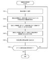
- a flowchart showing an example of the operation of the misplacement determination unit
- Flow chart showing an example of duplication judgment processing Diagram to illustrate the upper and lower margin compartments
- Flow chart showing an example of misplacement determination processing The first figure for explaining the details of the duplication analysis process.
- the second figure for demonstrating the details of the duplication analysis process.
- the figure for demonstrating the modification 1 of the misplacement determination The first figure for demonstrating the modification 2 of the misplacement determination
- the second figure for demonstrating the modification 2 of the misplacement determination A diagram showing the hardware configuration of a computer that realizes the functions of a monitoring device programmatically.
- FIG. 1 is a schematic diagram showing a configuration example of the monitoring system 20 according to the present embodiment.
- the store is provided with a display shelf 10 on which the article 2 is displayed.
- the monitoring system 20 is a system for monitoring the arrangement status of the article 2 on the display shelf 10.
- the article 2 may be read as another term such as a product or an article. Examples of the article 2 include various items such as daily necessities, food and drink, medicines, miscellaneous goods, and books.
- the display shelf 10 includes a shelf 11 on which the article 2 is placed and a shelf tag 12 installed in front of the shelf 11. On the shelf tag 12, for example, the name and price of the article 2 are described. Further, a QR code (registered trademark) for acquiring information about the article 2 may be described on the shelf label 12.
- the monitoring system 20 includes at least one camera device 21 and a monitoring device 100.
- the camera device 21 and the monitoring device 100 can send and receive data to and from each other via a wired and / or wireless communication network 22.
- Examples of the communication network 22 include a wired LAN (Local Area Network), a wireless LAN, a mobile communication network, an Internet network, and the like.
- the camera device 21 periodically photographs the display shelf 10, and transmits the captured image data (hereinafter referred to as “shelf image”) 121 (see FIG. 2) to the monitoring device 100.
- the shelf image 121 may be either a still image or a moving image.
- the monitoring device 100 receives the shelf image 121 from the camera device 21.
- the monitoring device 100 monitors the arrangement status of the article 2 on the display shelf 10 based on the received shelf image 121.
- a certain article 2 is arranged in a section different from the section (hereinafter referred to as “display section”) 200 (see FIG. 3) on which the article 2 should be displayed on the display shelf 10 (hereinafter referred to as “display section”).
- display section a section different from the section (hereinafter referred to as “display section”) 200 (see FIG. 3) on which the article 2 should be displayed on the display shelf 10 (hereinafter referred to as “display section”).
- misplacement When (referred to as "misplacement”) is detected, the occurrence of misplacement may be notified to, for example, a terminal owned by a clerk (hereinafter referred to as "misplacement notification"). As a result, the clerk can quickly notice the occurrence of the misplacement by the misplacement notification and return the
- a conventional device as disclosed in Patent Document 1 gives a misplacement notification when the article 2 is even slightly out of the display compartment 200. That is, even if the way the article 2 deviates from the display compartment 200 is acceptable to human senses, the misplacement notification is given. As a result, there arises a problem that the frequency of misplacement notifications to the clerk is too high, and the burden on the clerk is rather increased.
- the monitoring device 100 controls the determination of misplacement of the article 2 in the display section 200 based on the positional relationship between the article 2 and the display section 200. As a result, the misplacement notification is also controlled, and it is possible to prevent the burden on the clerk from increasing.
- the monitoring device 100 according to the present embodiment will be described.
- FIG. 2 is a functional block diagram showing a configuration example of the monitoring device 100 according to the present embodiment.
- the monitoring device 100 has the functions of an information storage unit 101, an image acquisition unit 102, a display area setting unit 103, an intermediate area setting unit 104, an article detection unit 105, a misplacement determination unit 106, and a misplacement notification unit 108. It should be noted that these functions may be realized by the cooperative operation of the hardware (see FIG. 13) included in the monitoring device 100.
- the information storage unit 101 stores information and data handled by the monitoring device 100.
- the information storage unit 101 may be realized by the RAM 1006 and the storage device 1007 shown in FIG.
- the image acquisition unit 102 receives the shelf image 121 from the camera device 21 via the communication network 22 and stores it in the information storage unit 101.
- the display section setting unit 103 sets the display section 200 (see FIG. 3) in the shelf image 121 based on the shelf allocation information 122 stored in the information storage section 101.
- the shelf allocation information 122 is information indicating which article 2 should be arranged in which section of the display shelf 10. The details of the shelf allocation information 122 will be described later (see FIG. 4).
- the display section setting unit 103 generates display section information 123 including information about the set display section 200 and stores it in the information storage section 101.
- the display compartment 200 may be set at the timing when the camera device 21 is installed and / or at any timing. The details of the display section setting unit 103 will be described later.
- the intermediate section setting unit 104 sets the intermediate section 201 (see FIG. 5) in the shelf image 121.
- the intermediate section 201 is a section used for determining the misplacement of the article 2, and is set adjacent to the display section 200.
- the intermediate section setting unit 104 generates the intermediate section information 124 including the information about the set intermediate section 201 and stores it in the information storage unit 101. The details of the intermediate section setting unit 104 and the intermediate section 201 will be described later.
- the article detection unit 105 analyzes the shelf image 121 and detects the image of the article 2.
- the article detection unit 105 includes an image area (hereinafter referred to as “article area”) 210 (see FIG. 3) of the detected article 2 and an article detection information including identification information of the detected article 2 (hereinafter referred to as “article information”). 125 is generated and stored in the information storage unit 101.
- the misplacement determination unit 106 determines whether or not each article area 210 included in the article detection information 125 is misplaced in relation to the display section 200.
- the misplacement determination unit 106 generates misplacement information 127 indicating the misplacement determination result and stores it in the information storage unit 101.
- the misplacement determination unit 106 may include the overlap analysis unit 107.
- the overlap analysis unit 107 analyzes the overlap of the article area 210 with respect to the display section 200 and the intermediate section 201.
- the duplication analysis unit 107 generates duplication analysis information 126 indicating the analysis result and stores it in the information storage unit 101.
- the misplacement determination unit 106 may determine whether or not the article area 210 is misplaced in relation to the display section 200 based on the overlap analysis information 126. The details of the misplacement determination unit 106 and the overlap analysis unit 107 will be described later.
- the misplacement notification unit 108 gives a misplacement notification based on the misplacement information 127.
- the misplaced notification may include the number of the display shelf 10 in which the misplaced article (hereinafter referred to as “misplaced article”) 2 is present.
- the misplacement notification may include an image in which a frame showing the article area 210 of the misplaced article 2 is added to the shelf image 121.
- the misplacement notification is, for example, transmitted to a terminal owned by a clerk. As a result, the clerk can receive the misplacement notification, recognize the occurrence of the misplacement, and return the misplaced article 2 to the correct display section 200.
- FIG. 3 is a diagram for explaining the setting of the display section 200 for the shelf image 121 and the detection of the article area 210.
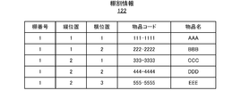
- FIG. 4 is a diagram showing an example of the configuration of the shelf allocation information 122.
- a section (display section 200) to be displayed for each article 2 is predetermined on the display shelf 10. That is, a certain defined article 2 is arranged in a certain display section 200.
- the display section 200 may be determined based on the position of the shelf tag 12 on the display shelf 10. For example, in the display section 200A of the article 2A indicated by the shelf tag 12A, the distance from the left end of the shelf tag 12A to the left end of the shelf tag 12B located to the right of the shelf tag 12A is set to a width W, and the shelf tag 12A is used. It may be a rectangular section having a vertical width H as the distance from the shelf 11A to which the is attached to the shelf 11B located above the shelf 11A. When the article 2A is arranged up to the upper part of the display shelf 10, the shelf stage 11B located above does not exist. In this case, the vertical width of the display section may be estimated based on the vertical width H in other shelves. Specifically, it is conceivable that the vertical width is the same as the vertical width H of the other shelves, or that the average value of the other vertical widths is regarded as the vertical width.
- the shelf allocation information 122 is information indicating the correspondence between the display section 200 in the display shelf 10 and the article information of the article 2 to be arranged in the display section 200.
- the shelf allocation information 122 has a shelf number, a vertical position, a horizontal position, an article code, and an article name as data items.
- the shelf number is a number for identifying the display shelf 10.
- the vertical position indicates the position in the vertical direction of the display section 200.
- the bottom shelf 11 of the display shelf 10 is set to "1", and the value increases by 1 toward the upper shelf 11.
- the horizontal position indicates the position in the horizontal direction of the display section 200.
- the leftmost position is "1”, and the value increases by 1 as it goes to the right. That is, the vertical position and the horizontal position are information for specifying the position of the display section 200 on the display shelf 10 indicated by the shelf number.
- the article code indicates a code for identifying the article.
- the article name indicates the name of the article.
- the article code and article name are examples of article information.
- the first line of the shelf allocation information 122 shown in FIG. 4 indicates the following. That is, in the display shelf 10 having the shelf number "1", the display section 200A (see FIG. 3) having the vertical position "1" and the horizontal position “1” has the article code "111-1111" and the article name "AAA”. Article 2A should be placed.
- the fourth line of the shelf allocation information 122 shown in FIG. 4 indicates the following. That is, in the display shelf 10 having the shelf number "1", the display section 200B (see FIG. 3) having the vertical position "2" and the horizontal position "2” has the article code "444-4444" and the article name "DDD”. Article 2D should be placed.
- the display section setting unit 103 sets the display section 200 for the shelf image 121 based on the shelf allocation information 122. For example, the display section setting unit 103 sets the section in the shelf image 121 corresponding to the shelf number “1”, the vertical position “1”, and the horizontal position “1” indicated by the shelf allocation information 122 to the article code “111-1111”. And, it is set in the display section 200A of the article 2A indicated by the article name "AAA”. For example, the display section setting unit 103 sets the section in the shelf image 121 corresponding to the shelf number “1”, the vertical position “2”, and the horizontal position “2” indicated by the shelf allocation information 122 to the article code “444-4444”. And, it is set in the display section 200D of the article 2D indicated by the article name "DDD".
- the display section setting unit 103 may detect the shelf tag 12 on the display shelf 10 by image recognition, wireless communication, or the like, and set the display section 200 using the position of the shelf tag 12. For example, when the shelf tag 12A is detected from the shelf image 121, the display section setting unit 103 sets the section existing in the upper right of the position where the shelf tag 12A is detected as the display section 200A. The display section setting unit 103 may determine which display section 200 the shelf tag 12A corresponds to based on the detected position of the shelf tag 12 and the shelf allocation information 122. Further, the display section setting unit 103 corresponds to the shelf label 12 by reading the characters of the shelf label 12 by OCR (Optical Character Recognition) or by using the wireless communication function provided in the shelf label 12 itself.
- OCR Optical Character Recognition
- the display section 200 may be set based on the product name by recognizing the product name.
- the display section 200 corresponding to the shelf tag 12 is set at the upper right of the position where each shelf tag 12 is detected.
- the settings may be made according to the rules. For example, when the rule that the shelf label 12 is arranged at the lower right of each display section 200 is adopted, the display section setting unit 103 may set the section located at the upper left of the shelf tag 12A as the display section 200A. ..
- the display section setting unit 103 may set the display section 200 in the display shelf 10 based on the shelf image 121 obtained by photographing the display shelf 10 in which the article 2 is correctly arranged. For example, the display section setting unit 103 detects the article 2 from the shelf image 121, and sets the section in which the common article 2A is detected in the display section 200A of the article 2A. Alternatively, the display section setting unit 103 detects the article 2 from the left to right for each shelf 11 from the shelf image 121, and sets the section in which the common article 2A is continuously detected as one display section 200A. good. In this case, the position where the different article 2B is detected may be the starting position of the new display compartment 200B. In this case, since the position of the shelf tag 12 is not used for setting the display section 200, the display section setting unit 103 also sets the display section 200 for the shelf image 121 of the display shelf 10 in which the shelf tag 12 is not installed. Can be set.
- the article detection unit 105 performs image analysis for detecting the article 2 on the shelf image 121, and detects the article region 210.
- Image recognition technology based on pattern matching or artificial intelligence may be used for image analysis to detect the article 2.
- a learning device generated in advance by deep learning may be used.
- the article detection unit 105 has an article area 210A of the article name "AAA”, an article area 210B of the article “BBB”, an article area 210C of the article name “CCC”, and an article name “DDD”. ”, And the article area 210E of the article name“ EEE ”is detected. Then, the article detection unit 105 generates the article detection information 125 by associating the position of each article area 210 in the shelf image 121 with the article name (that is, article information) of the article area 210.
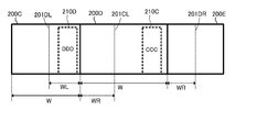
- FIG. 5 is a diagram for explaining the setting of the intermediate section 201 with respect to the shelf image 121.
- the description will be focused on the display compartment 200D, but the same applies to the other display compartments 200A, 200B, 200C, and 200E.
- the intermediate section setting unit 104 sets the intermediate section 201DL on the left side of the display section 200D and the intermediate section 201DR on the right side of the display section 200D.
- the intermediate compartments 201DL and 201DR are used to determine the misplacement of the article 2D (article area 210D) to be arranged in the display compartment 200D.
- the width WL of the intermediate section 201DL is equal to or less than the width W of the display section 200C to the left of the display section 200D.
- the width WL of the intermediate section 201DL may be the same as the width W of the display section 200C adjacent to the left.
- the width WR of the intermediate section 201DR is equal to or less than the width W of the display section 200E to the right of the display section 200D.
- the width WR of the intermediate section 201DR may be the same as the width W of the display section 200E adjacent to the right.
- the intermediate section 201DL and the intermediate section 201DR are typically sections used for determining whether or not the protrusion is acceptable when the article protrudes from the display section 200D and is displayed.
- the width WL of the intermediate section 201DL and the width WR of the intermediate section 201DR are set to be equal to or less than the width of the adjacent display sections. If the widths WL and WR of the intermediate sections 201DL and 201DR are narrower, the area that can be determined to be “not erroneous display” becomes narrower, and if it is widened, the area that can be determined to be “not erroneous display” becomes. It gets wider.
- the widths WL and WR of the intermediate sections 201DL and 201DR may be adjustable depending on how strict the misdisplay should be determined. Further, the widths WL and WR of the intermediate sections 201DL and 201DR, respectively, may be individually adjustable. By doing so, it is possible to make a difference in the strictness of determination for each of the intermediate sections 201DL and 201DR.
- the width WL and WR of the intermediate sections 201DL and 201DR may be set uniformly. By doing so, it is not necessary to individually adjust the widths WL and WR of each intermediate section 201DL and 201DR, so that the width of the intermediate section 201 can be easily set.
- the widths WL and WR of the intermediate compartments 201DL and 201DR may be set according to the width W of the display compartment 200D.
- the widths WL and WR of the intermediate compartments 201DL and 201DR may be set as n 1 % (0 ⁇ n 1 ⁇ 100) of the width W of the display compartment 200D.
- the widths WL and WR of the intermediate compartments 201DL and 201DR may be set according to the width Wg of the article region 210D to be arranged in the display compartment 200D.
- the widths WL and WR of the intermediate compartments 201DL and 201DR may be set as n 2 % (0 ⁇ n 2 ⁇ 100) of the width Wg of the article region 210D to be arranged in the display compartment 200D.
- the wider the item the more likely it is to protrude into the adjacent section.
- the width occupied by the article becomes wider as the width Wg of the article is wider.
- the intermediate section 201 having the same width WL and WR as the article having a narrow width Wg is set, the article area 210 of the article having a wide width Wg protrudes from the intermediate section 201, and an appropriate determination can be made. become unable.
- the intermediate section 201 of the same width WL and WR as that for the wide article is set for the article having a narrow width Wg, even if a large number of articles are arranged in the adjacent section, "wrong". Since it can be determined that it is not a display, the result will be inconsistent with human senses.
- Such a problem can be solved by setting the widths WL and WR of the intermediate section 201 according to the width Wg of the article.
- the width Wg of the article is likely to be proportional to the width W of the display compartment 200 in which the article is to be placed, and it is unlikely that the narrow display compartment 200 will be assigned to at least the article having a large width Wg.
- the intermediate section 201 having a width proportional to the width Wg of the article can be easily set. Further, if the article region 210 can be accurately detected, the widths WL and WR of the intermediate compartment 201 may be set according to the width Wg of the article region 210 to be arranged in the display compartment 200. Thereby, the width Wg of the article can be strictly reflected in the width WL and WR of the intermediate section 201.
- the widths WL and WR of the intermediate section 201 may be set individually for each display section 200.
- the width WL and the width WR of the intermediate section 201 may be set to the same value or may be set to different values from each other.
- the values of the widths WL and WR of the intermediate sections 201DL and 201DR may be expressed by the number of pixels.
- the width WL and WR of the intermediate section 201 are the width of the display section 200 (that is, the section in which the adjacent articles should be displayed) overlapping the intermediate section 201. You may not exceed. If the width WL and WR of the intermediate section 201 calculated or set by the above method exceed the width of the display section 200 that overlaps the intermediate section 201, the excess is cut off and the display overlaps with the intermediate section 201. It may be rounded to the same value as the width of the compartment 200. Since the intermediate section 201 is an area that can be determined not to be misplaced, if it is set beyond the display section 200 that overlaps with the intermediate section 201, it reaches the area where two adjacent articles should be originally placed. This is because even if a large misplacement that causes the article to protrude occurs, it may be determined that the misplacement is not the case.
- the intermediate section setting unit 104 may set a group composed of a plurality of display sections 200 in the intermediate section 201.
- the intermediate section setting unit 104 may set a plurality of display sections 200 of the same shelf 11 as one group, and set the group in the intermediate section 201.
- the intermediate section setting unit 104 may set a plurality of display sections 200 on which designated articles (for example, articles of the same manufacturer) are displayed as one group, and set the group in the intermediate section 201.
- such a setting may be made when the manufacturer or the like that provides the goods requires the arrangement on a specific shelf stage 11, but the arrangement within the shelf stage 11 may be arbitrary.
- the misplacement determination unit 106 determines that the article 2 is misplaced. You don't have to. That is, the misplacement determination unit 106 may allow the replacement of the arrangement of the articles 2 in the group.
- FIG. 6 is a flowchart showing an example of the operation of the misplacement determination unit 106. Next, an example of the processing of the misplacement determination unit 106 will be described with reference to FIG.
- the misplacement determination unit 106 refers to the article detection information 125 and selects one article area 210 to be processed from the plurality of article areas 210 detected from the shelf image 121 (S101).
- the misplacement determination unit 106 refers to the display section information 123 and selects one display section 200 to be processed from the plurality of display sections 200 set in the shelf image 121 (S102).
- the duplication analysis unit 107 executes a duplication analysis process for the display section 200 selected in S102 for the article area 210 selected in S101 (S103). The details of the duplication analysis process will be described later.
- the misplacement determination unit 106 determines whether or not all the display sections 200 have been selected (S104). When the unselected display compartment 200 remains (S104: NO), the misplacement determination unit 106 returns to the processing of S102 and selects one of the remaining display compartments 200 as the processing target. When the selection of all the display compartments 200 is completed (S104: YES), the misplacement determination unit 106 proceeds to the next processing of S105.
- the misplacement determination unit 106 determines whether or not the selection of all the article areas 210 has been completed (S105). When the unselected article area 210 remains (S105: NO), the misplacement determination unit 106 returns to the process of S101 and selects one of the remaining article areas 210 as the processing target. When the selection of all the article areas 210 is completed (S105: YES), the misplacement determination unit 106 proceeds to the next process of S106.
- the misplacement determination unit 106 executes the misplacement determination process in each display section 200 (S106). The details of the misplacement determination process will be described later. Then, the misplacement determination unit 106 ends this process.
- FIG. 7 is a flowchart showing an example of the duplication analysis process.
- the flowchart corresponds to the details of the process of S103 in FIG. Further, in the explanation of the flowchart, the article area 210 is selected in S101 of FIG. 6, and the display section 200 is selected in S102 of FIG.
- the duplication analysis unit 107 determines whether or not at least a part of the article area 210 overlaps with a section (hereinafter referred to as “synthesis section”) in which the display section 200 and the intermediate section 201 adjacent to the display section 200 are combined. Judgment (S201).
- the overlap analysis unit 107 ends this process when the article region 210 does not overlap with the synthesis section (S201: NO). In this case, the article area 210 will be determined to overlap in another synthesis section. When at least a part of the article region 210 overlaps with the synthesis section (S201: YES), the duplication analysis unit 107 proceeds to the next processing of S202.
- the overlap analysis unit 107 determines whether or not at least a part of the article area 210 protrudes from the upper and lower margin sections 230 (see FIG. 8) (S202).
- the upper and lower margin sections 230 may be set above and below the display section 200 with a predetermined vertical width Hm.
- the vertical width Hm of the upper margin section 230 and the vertical width Hm of the lower margin section 230 may be common or different from each other. Further, the margin section 230 may not be set. In this case, the duplication analysis unit 107 proceeds to the process of S203 without executing the process of S202.
- the overlap analysis unit 107 ends this process. That is, the duplication analysis unit 107 does not perform duplication analysis on the article area 210.
- the overlap analysis unit 107 proceeds to the next process of S203.
- the vertical width of the shelf stage 11 is limited by a shelf board or the like, and the arrangement of the articles 2 in the vertical direction is physically restricted as compared with the arrangement of the articles 2 in the horizontal direction.
- the protrusion in the vertical direction it is highly possible that the article 2 having a height different from that of the article 2 that should be originally arranged is arranged, and whether such an arrangement is acceptable or not. There is a high possibility that it is misplaced without making a judgment. Therefore, in the present embodiment, when the protrusion in the vertical direction occurs, the duplicate analysis process that leads to the determination of whether or not the protrusion is acceptable is not performed.
- the size of the article area 210 in the vertical direction can be variously changed, such as when an arbitrary number of articles 2 can be stacked or the angle of the articles 2 to be displayed can be changed, the vertical direction is used. If the protrusion is strictly evaluated, the result will be different from the feeling of the clerk. In such a case, the processing of S202 may be omitted.
- the duplication analysis unit 107 calculates the degree of duplication of the article area 210 with respect to the display section 200 and the intermediate section 201 (S203). The details of the calculation of the multiplicity will be described later.
- the duplication analysis unit 107 writes the display section 200 and the article area 210 in the duplication analysis information 126 in association with the calculated degree of duplication (S204). Then, the duplication analysis unit 107 ends this process.
- FIG. 9 is a flowchart showing an example of misplacement determination processing. The flowchart corresponds to the details of the process of S106 of FIG.
- the misplacement determination unit 106 refers to the display section information 123 and selects one display section 200 to be processed from the plurality of display sections 200 set in the shelf image 121 (S301).
- the erroneous display determination unit extracts from the duplication analysis information 126 each article area 210 associated with the display section 200 selected in S301 and the degree of overlap with respect to the article area 210 (S302).
- the misplacement determination unit 106 determines whether or not the misplacement of the article area 210 has occurred in the display section 200 selected in S301 based on the degree of duplication extracted in S302 (S303).
- the misplacement determination unit 106 determines whether or not the article region 210 extracted in S301 is misplaced based on the degree of overlap extracted in S302 (S304). The details of the method for determining misplacement based on the degree of duplication will be described later.
- the misplacement determination unit 106 writes the determination results of S303 and S304 in the misplacement information 127 (S305). As described above, the misplacement information 127 is used for misplacement notification by the misplacement notification unit 108.
- the misplacement determination unit 106 determines whether or not the selection of all the display compartments 200 has been completed (S306). When the unselected display compartment 200 remains (S306: NO), the misplacement determination unit 106 returns to the processing of S301 and selects one of the remaining display compartments 200 as the processing target. When the misplacement determination unit 106 completes the selection of all the display compartments 200 (S306: YES), the misplacement determination unit 106 ends this process.
- 10A and 10B are diagrams for explaining the details of the duplication analysis process.
- FIGS. 10A and 10B an example of the duplication analysis processing when the article area 210D and the display compartment 200D are selected as the processing targets for the duplication analysis will be described in detail.
- the overlap analysis unit 107 determines the degree of overlap of the article area 210D with the display section 200D as follows. Calculate to. That is, the overlap analysis unit 107 sets the degree of overlap of the article area 210D with respect to the display section 200D to "1.0", the degree of overlap of the article area 210D with respect to the intermediate section 201DL to "0", and the degree of overlap of the article area 210D with respect to the intermediate section 201DR. Is calculated as "0".
- the degree of overlap of the article area 210D with respect to the display section 200D may mean the degree of overlap of the width Wg of the article area 210 with respect to the width W of the display section 200D.
- the degree of overlap of the article region 210D with respect to the intermediate compartment 201DL may mean the degree of overlap of the width Wg of the article region 210D with respect to the width WL of the intermediate compartment 201DL.
- the degree of overlap of the article region 210D with respect to the intermediate compartment 201DR may mean the degree of overlap of the width Wg of the article region 210D with respect to the width WR of the intermediate compartment 201DR.
- the degree of overlap of the article area 210D with respect to the display section 200D may mean the degree of overlap of the area of the article area 210 with respect to the area of the display section 200D.
- the degree of overlap of the article region 210D with respect to the intermediate compartment 201DL may mean the degree of overlap of the area of the article region 210D with respect to the area of the intermediate compartment 201DL.
- the degree of overlap of the article region 210D with respect to the intermediate compartment 201DR may mean the degree of overlap of the area of the article region 210D with respect to the area of the intermediate compartment 201DR.
- the multiplicity analysis unit 107 overlaps the article region 210D.
- the degree of overlap in relation to the display compartment 200D is calculated as follows. That is, the overlap analysis unit 107 has an overlap degree of the article area 210D with respect to the display section 200D of "0.7", an overlap degree of the article area 210D with respect to the intermediate section 201DL of "0.3", and an overlap degree of the article area 210D with respect to the intermediate section 201DR.
- the degree of duplication is calculated as "0".
- the overlap analysis unit 107 determines the degree of overlap of the article area 210D with the display section 200D as follows. Calculate to. That is, the overlap analysis unit 107 sets the degree of overlap of the article area 210D with respect to the display section 200D to "0", the degree of overlap of the article area 210D with respect to the intermediate section 201DL to "1.0", and the degree of overlap of the article area 210D with respect to the intermediate section 201DR. Is calculated as "0".
- the overlap analysis unit 107 calculates the degree of overlap of the article region 210D in relation to the display compartment 200D. It doesn't have to be. In this case, since the article area 210D overlaps 100% with the display section 200C, the degree of overlap in the relationship between the article area 210D and the display section 200C is calculated.
- the overlap analysis unit 107 determines the degree of overlap of the article area 210C with the display section 200D as follows. Calculate to. That is, the overlap analysis unit 107 sets the degree of overlap of the article area 210C with respect to the display section 200D to "1.0", the degree of overlap of the article area 210C with respect to the intermediate section 201DL to "0", and the degree of overlap of the article area 210C with respect to the intermediate section 201DR. Is calculated as "0".
- the multiplicity analysis unit 107 overlaps the article region 210C.
- the degree of overlap in relation to the display compartment 200D is calculated as follows. That is, the overlap analysis unit 107 sets the degree of overlap of the article area 210C with respect to the display section 200D to "0.7", the degree of overlap of the article area 210C with respect to the intermediate section 201DL to "0", and the degree of overlap of the article area 210C with respect to the intermediate section 201DR. Is calculated as "0".
- the overlap analysis unit 107 calculates the degree of overlap of the article area 210C with respect to the display section 200C as "0.3" and the degree of overlap of the article area 210C with respect to the intermediate section 201CR as "0.7".
- the overlap analysis unit 107 overlaps the article area 210E.
- the degree of overlap in relation to the display section 200D and the degree of overlap in relation to the display section 200E of the article area 210E are calculated as follows. That is, the overlap analysis unit 107 sets the degree of overlap of the article area 210E with respect to the display section 200D to "0.7", the degree of overlap of the article area 210E with respect to the intermediate section 201DL to "0", and the degree of overlap of the article area 210E with respect to the intermediate section 201DR. Is calculated as "0". Further, the overlap analysis unit 107 calculates the degree of overlap of the article area 210E with respect to the display section 200C as "0.3" and the degree of overlap of the article area 210E with respect to the intermediate section 201CR as "0".
- the degree of overlap in relation to the display section 200 of the article area 210 described above is written in the overlap analysis information 126.
- the misplacement determination unit 106 makes a misplacement determination for the article area 210 having a degree of overlap with the display section 200D greater than 0. Further, the misplacement determination unit 106 associates the article area 210 from which the misplacement determination result is obtained with the appropriate display section 200, and sets the determination result of the article area 210 as the determination result for the display section 200. This processing is performed in a different procedure as described below, depending on whether or not the article area 210 should be displayed in the display compartment 200D to be processed.
- the misplacement determination unit 106 uses the determination result for the article area 210 as the determination result for the display section 200 to be processed. The details of the determination process are shown below.
- the misplacement determination unit 106 is the sum of the degree of overlap of the article area 210D with respect to the display section 200D, the degree of overlap of the article area 210D with respect to the intermediate section 201DL, and the total degree of overlap of the article area 210D with respect to the intermediate section 201DR (hereinafter, “total degree of overlap”). ”) Is equal to or higher than a predetermined threshold value T, it may be determined that the article region 210D is not misplaced (that is, is correctly placed). In other words, the misplacement determination unit 106 may determine that the article area 210D is misplaced when the total degree of overlap with respect to the article area 210D is less than the threshold value T.
- the degree of overlap of the article area 210D with respect to the display section 200D is the degree of overlap of the article area 210D with respect to the intermediate section 201DL and the intermediate section 201DR of the article area 210D. If it is smaller than the total of the degree of overlap with respect to the above, the misplacement determination unit 106 may determine that the article area 210D is suspected of being misplaced (hereinafter referred to as "suspicious placement").
- the assumed situation may differ depending on the cause determined to be the suspicious arrangement, different notifications may be given for each cause. If it is not necessary to distinguish the suspicious arrangement from other states, it may be determined as either a normal arrangement or an incorrect arrangement. In addition, it may be possible to switch whether or not it is necessary to distinguish the suspicious arrangement from other states by the instruction of the clerk or the like.
- the article area 210D should be displayed in the display section 200D.
- the degree of overlap of the article area 210D with respect to the display section 200D is "1.0"
- the degree of overlap of the article area 210D with respect to the intermediate section 201DL is "0”
- the degree of overlap of the article area 210D with respect to the intermediate section 201DR is "0".
- T is set to "0.8”
- the total degree of overlap "1.0" with respect to the article region 210D is equal to or higher than the threshold value T "0.8".
- the overlap degree "1.0" of the article area 210D with respect to the display section 200D is the sum of the overlap degree "0" of the article area 210D with respect to the intermediate section 201DL and the overlap degree "0" of the article area 210D with respect to the intermediate section 201DR. It is "0" or more. Therefore, the misplacement determination unit 106 may determine that the article region 210D is in the normal placement.
- the article area 210D should be displayed in the display section 200D.
- the degree of overlap of the article area 210D with respect to the display section 200D is "0.7"
- the degree of overlap of the article area 210D with respect to the intermediate section 201DL is "0.3”
- the degree of overlap of the article area 210D with respect to the intermediate section 201DR is "0”. Is. Therefore, the total degree of overlap with respect to the article region 210D is "1.0", which is equal to or higher than the threshold value T "0.8".
- the misplacement determination unit 106 may determine that the article region 210D is in the normal placement.
- the degree of overlap of the article area 210D with respect to the display section 200D is "0.2"
- the degree of overlap of the article area 210D with respect to the intermediate section 201DL is "0.8”
- the degree of overlap of the article area 210D with respect to the intermediate section 201DR is "0".
- the total degree of overlap with respect to the article region 210D is "1.0", which is equal to or higher than the threshold value T "0.8”.
- the degree of overlap "0.2" of the article area 210D with respect to the display section 200D is the degree of overlap of the article area 210D with respect to the intermediate section 201DL "0.8” and the degree of overlap of the article area 210D with respect to the intermediate section 201DR "0". It is smaller than the total "0.8". Therefore, the misplacement determination unit 106 may determine that the article area 210D is a suspicious arrangement.
- the misplacement determination unit 106 needs to not only determine that the article area 210C is misplaced, but also determine which display section 200 the misplacement is for. Unlike the case where the article area 210 should be displayed in the display section 200 to be processed, the display section 200 in which the article area 210C overlaps does not have a section clearly associated with the article area 210C. Is. Therefore, the misplacement determination unit 106 determines which display section 200 the misplacement determination result is associated with, based on the degree of overlap between the article area 210C and each display section 200 to be processed.
- the degree of overlap of the article area 210C with respect to the display section 200D is "1.0"
- the article area 210C is misplaced across a plurality of display sections 200
- the display section 200C overlaps with the overlap degree "0.3”, and when the overlap degree 200D overlaps with the overlap degree "0.7", the article area.
- the degree of overlap of 210C does not exceed the threshold value in either display compartment 200C or 200D.
- a "straddling coefficient ⁇ " that adjusts the threshold value according to the number of straddling display sections 200 is used.
- the misplacement determination unit 106 may make the following determination when the degree of overlap with the display section 200D of the article area 210C is not "1.0". That is, when the degree of overlap of the article area 210C with respect to the display section 200D is equal to or greater than the value obtained by multiplying the predetermined straddle coefficient ⁇ by the threshold value T, the misplacement determination unit 106 erroneously sets the article area 210C in the display section 200D. It may be determined that it is an arrangement.
- the misplacement determination unit 106 determines that the article area 210C is misplaced in the display section 200D. It is not necessary to determine that there is.
- the straddle coefficient ⁇ may be a constant.
- the straddle coefficient ⁇ may be a variable that changes according to the number of display compartments 200 in which the article regions 210 overlap. For example, when the article area 210 overlaps with two display sections 200, the straddle coefficient ⁇ is “1/2”, and when the article area 210 overlaps with three display sections 200, the straddle coefficient ⁇ is “1/3”. It may be there.
- the misplacement determination unit 106 may determine that the article area 210C is misplaced.
- the article area 210E should not be arranged in the display section 200D.
- the straddle coefficient ⁇ is set to “0.5”
- the degree of overlap “0.7” with respect to the display section 200D of the article area 210E sets the threshold value T “0.8” to the straddle coefficient ⁇ “0.5”.
- the multiplied value is "0.45" or more. Therefore, the misplacement determination unit 106 may determine that the article region 210E is misplaced.
- the misplacement determination unit 106 does not have to make a determination for the article region 210E.
- the misplacement determination unit 106 can link the article area 210 to the display section 200 without exception. Therefore, it is possible to notify the store clerk or the like in which display section 200 the misplacement or the like has occurred.
- the process of associating the article area 210 with the misplaced article area 200 with any of the display areas 200 is performed. As a result, it is possible to notify the store clerk or the like of the position where the misplacement has occurred (display section 200), so that the misplacement can be corrected more easily.
- the determination result by the misplacement determination unit 106 is not limited to the above-mentioned correct placement, misplacement, and suspicious placement.
- the misplacement determination unit 106 may use the degree of overlap of the article area 210 with respect to the display section 200 and / or the intermediate section 201 as the determination result.
- the misplacement determination unit 106 may use that fact as the determination result.
- the misplacement determination unit 106 may use that fact as the determination result. In this case, it may be displayed at the same time whether or not it is protruding and whether it is a normal arrangement, a misalignment, or a suspicious arrangement.
- the clerk can evaluate whether or not the strictness of the determination of the misplacement determination unit 106 is appropriate. In particular, if the clerk can manually adjust the parameters that affect the determination of whether or not the arrangement is correct, the necessity of adjustment can be determined more accurately.
- FIG. 11 is a diagram for explaining a modification 1 of the misplacement determination.
- the misplacement determination unit 106 determines that the article area 210D is not misplaced, and as shown in FIG. 12, a plurality of article areas 210D in the intermediate section 201DL. If 210D is present, it may be determined that the plurality of article areas 210D are misplaced.
- FIGS. 12A and 12B are diagrams for explaining a modification 2 of the misplacement determination.
- misplaced determination unit 106 is an article region 210 existing in the intermediate compartment 201, but these article regions 210 are interchanged with the display compartment 200 adjacent to each other, these article regions 210 may be determined to be misplaced.
- the article region 210D exists in the intermediate compartment 201DL, and the article region 210C exists in the intermediate compartment 201CR.
- the misplacement determination unit 106 determines that the article areas 210D and 210C are misplaced. You can do it. In the judgment based on one display section 200 and the corresponding intermediate section 201, it is not possible to distinguish between the case where the entire display is slightly shifted to the left and right and the case where the articles 2 are exchanged between the adjacent display sections 200. In either case, it is only known that the intermediate section 201 contains the correct article 2.
- the replacement of the article area 210 is a misarrangement that is relatively likely to occur when a store clerk or the like displaying the article 2 misrecognizes the order of arrangement. Therefore, in this modification, when the article regions 210 are interchanged with the display compartments 200 adjacent to each other, it is determined that misalignment has occurred, so that one display compartment 200 is focused on. It has detected a misplacement that would be overlooked if it was present.
- the misplacement determination unit 106 has the intermediate compartments 201DL and 201CL and the article. Regardless of the positional relationship with the regions 210C and 210D, these article regions 210C and 210D may be determined to be misplaced. This is because, when the replacement is confirmed, it is not necessary to confirm the positional relationship with the intermediate sections 201Dl and 201CL, and the arrangement is erroneous.
- both article regions 210C and 210D in which the replacement has occurred are determined to be misplaced, but one of the article regions 210C (or 210D) may be determined to be misplaced.
- FIG. 13 is a diagram showing a hardware configuration of a computer that realizes the function of the monitoring device 100 by a program.
- the computer 1000 includes an input device 1001 such as a keyboard or mouse and a touch pad, an output device 1002 such as a display or a speaker, a CPU (Central Processing Unit) 1003, a GPU (Graphics Processing Unit) 1004, and a ROM (Read Only Memory) 1005.
- Read information from a recording medium such as a RAM (RandomAccessMemory) 1006, a hard disk device or a storage device 1007 such as an SSD (SolidStateDrive), a DVD-ROM (DigitalVersatileDiskReadOnlyMemory) or a USB (UniversalSerialBus) memory.
- a reading device 1008 and a transmitting / receiving device 1009 that communicates via a communication network are provided, and each unit is connected by a bus 1010.
- the reading device 1008 reads the program from the recording medium on which the program for realizing the function of the monitoring device 100 is recorded, and stores the program in the storage device 1007.
- the transmission / reception device 1009 communicates with the server device connected to the communication network, and stores the program for realizing the function of the monitoring device 100 downloaded from the server device in the storage device 1007.
- the CPU 1003 copies the program stored in the storage device 1007 to the RAM 1006, and sequentially reads and executes the instructions included in the program from the RAM 1006, whereby the function of the monitoring device 100 is realized.
- LSI is an integrated circuit. These may be individually integrated into one chip, or may be integrated into one chip so as to include a part or all of them. Although it is referred to as LSI here, it may be referred to as IC, system LSI, super LSI, or ultra LSI depending on the degree of integration.
- only one of the intermediate section 201DL and the intermediate section 201DL may be provided.
- the display section 200 is located at the right end of the display shelf 10, it is extremely unlikely that an acceptable misalignment will occur in the right intermediate section 201DR, so only the left intermediate section 201DL may be provided.
- the present disclosure can be applied to a display having a form different from that of the display shelf 10. ..
- it can be applied to the determination of the misplacement of the articles 2 arranged in a plane and the determination of the misplacement of the displayed articles 2 stacked in the vertical direction.
- the intermediate section 201 may be set at a position adjacent to the display section 200 in the vertical direction.
- the intermediate section 201 may be set at positions adjacent to the display section 200 on the top, bottom, left, and right of the display section 200. Further, in order to further widen the range in which misplacement is allowed, the intermediate section 201 may be set at positions adjacent to each other in the diagonal direction.
- the monitoring device (100) for monitoring the arrangement of the article (2) according to the present disclosure includes an image acquisition unit (102) for acquiring an image (121) of the arranged article, and the article is displayed on the image. Next to the display section setting unit (103) that sets the display section (200) that should be set, and the intermediate section (201) that is used for determining the misplacement of the article is set next to the display section in the image.
- An intermediate section setting unit (104) an article detection unit (105) that detects an article area (210) that is an image area of an article from an image, and at least a part of the detected article area overlap with the display section. If not, it is provided with a misplacement determination unit (106) for determining whether or not the article area is misplaced in relation to the display section based on the positional relationship between the article area and the intermediate section. ..
- the article area when at least a part of the article area does not overlap with the display area, the article area is the display area based on the positional relationship between the intermediate area and the article area set next to the display area. It is determined whether or not the arrangement is incorrect in relation to. Therefore, by adjusting the setting of the intermediate section, it is possible to flexibly control the determination of misplacement.
- the misplacement determination unit may determine that the article area is not misplaced in relation to the display section.
- the misplacement determination unit may determine that the article area is not misplaced in relation to the display section.
- the misplacement determination unit may determine the possibility of misplacement in relation to the display section of the article area based on the overlap ratio with respect to the display section and the intermediate section of the article area.
- the possibility of misplacement of the article area is determined based on the overlap ratio of the article area with respect to the display section and the intermediate section. Therefore, by adjusting the determination criteria for the duplication ratio, it is possible to flexibly control the determination of misplacement.
- the misplacement determination unit sets the article area as the display section. It may be determined that there is no misalignment in relation to.
- the misplacement determination unit sets the article area as the display section. It may be determined that there is a suspicion of misplacement in relation to.
- the misplacement determination unit may determine that the at least two article areas are misplaced in relation to the display section.
- misplacement of the article area is determined according to the number of article areas included in the intermediate section. Therefore, it is possible to flexibly control the determination of misplacement according to the number of article regions included in the intermediate section.
- the article area of the article to be displayed in the display section and the article area of the article to be displayed in another display section adjacent to the display section are the display section and the other display section.
- the intermediate section setting unit may set the width of the intermediate section that overlaps with other display sections adjacent to the display section to a width that does not exceed the other display sections. Further, the intermediate section setting unit may set the width of the intermediate section that overlaps with the other display section to the same width as the other display section.
- the width of the intermediate section overlapping with the other display section adjacent to the display section is set so as not to exceed the width of the other display section or to be the same as the width of the other display section. Will be done.
- an intermediate section is set even in another display section two adjacent to the display section, and the article to be placed in the display section is arranged in the other display section two adjacent to the display section. Nevertheless, it is possible to prevent it from being determined that it is not misplaced. That is, it is possible to prevent the output of the determination result of misplacement that is inconsistent with the human sense.
- the misplacement determination unit may determine the display section corresponding to the article area and output the misplacement determination result for the article area as the misplacement determination result for the display section corresponding to the article area.
- the misplacement determination result for the article area is output as the mislocation determination result for the display section corresponding to the article area.
- the technology disclosed in this disclosure is useful for monitoring the placement status of articles.
Landscapes
- Engineering & Computer Science (AREA)
- Physics & Mathematics (AREA)
- General Physics & Mathematics (AREA)
- Theoretical Computer Science (AREA)
- Computer Vision & Pattern Recognition (AREA)
- Business, Economics & Management (AREA)
- Finance (AREA)
- Accounting & Taxation (AREA)
- Geometry (AREA)
- Quality & Reliability (AREA)
- Development Economics (AREA)
- Economics (AREA)
- Marketing (AREA)
- Strategic Management (AREA)
- General Business, Economics & Management (AREA)
- Management, Administration, Business Operations System, And Electronic Commerce (AREA)
- Display Racks (AREA)
Abstract
監視装置は、配置された物品が撮影された画像を取得し、画像に物品が陳列されるべき区画である陳列区画を設定し、画像における陳列区画の隣に物品の誤配置の判定に用いられる区画である中間区画を設定し、画像から物品の画像領域である物品領域を検出し、検出された物品領域の少なくとも一部が陳列区画と重複していない場合に物品領域と中間区画との位置関係に基づいて、物品領域が陳列区画との関係において誤配置であるか否かを判定する。
Description
本開示は、監視装置、監視方法、及び、コンピュータプログラムに関する。
店舗に設置された、商品が陳列される棚(以下「陳列棚」という)は、商品が配置されるべき区画が棚割りとして予め定められる。しかし、店員が陳列棚の誤った区画に商品を配置したり、客が陳列棚から一度取った商品を誤った区画に置き直したりして、商品が誤った区画に配置(以下「誤配置」という)される状況が発生し得る。そのため、店員は、陳列棚において誤配置が発生していないかを確認したり、誤配置されている商品を正しい区画に置き直したりする作業を行う。この作業は店員にとって大きな負担となっている。
この作業負担を軽減するために、陳列棚の棚割りを示す情報(どの商品がどの陳列棚のどの区画に配置されるべきかを示す情報であり、プラノグラムとも呼ばれる)と、陳列棚における商品の実際の配置状況を示す情報(リアログラムとも呼ばれる)とを比較し、商品が陳列棚の正しい区画に配置されている否かを判定する技術が知られている。
例えば、特許文献1には、陳列棚をカメラ装置で撮影した画像を解析して、陳列棚における商品の配置状況を特定し、その特定した商品の配置状況が、陳列棚における商品の正しい配置状況と異なる場合、エラーを出力することが開示されている。
しかしながら、特許文献1に開示されている技術は、商品の配置状況が、陳列棚における商品の正しい配置状況と少しでも異なると、エラーを出力する。そのため、商品の配置状況と、陳列棚における商品の正しい配置状況との違いが、人間の感覚では許容し得るぐらいのもの(一例として、商品が正しい配置位置からわずかにはみ出している場合など)であっても、エラーが出力されてしまう。その結果、店員が商品を陳列棚の正しい区画に戻す作業が増えてしまい、店員の作業量がかえって高くなってしまうという課題がある。
本開示の目的は、陳列棚における商品の誤配置の判定を柔軟に制御することにある。
本開示の一態様に係る監視装置は、物品の配置を監視する監視装置であって、配置された前記物品が撮影された画像を取得する画像取得部と、前記画像に、前記物品が陳列されるべき区画である陳列区画を設定する陳列区画設定部と、前記画像における前記陳列区画の隣に、前記物品の誤配置の判定に用いられる区画である中間区画を設定する中間区画設定部と、前記画像から、前記物品の画像領域である物品領域を検出する物品検出部と、検出された前記物品領域の少なくとも一部が前記陳列区画と重複していない場合に、前記物品領域と前記中間区画との位置関係に基づいて、前記物品領域が前記陳列区画との関係において誤配置であるか否かを判定する誤配置判定部とを備える。
本開示の一態様に係る監視方法は、装置によって物品の配置を監視する監視方法であって、配置された前記物品が撮影された画像を取得し、前記画像に、前記物品が陳列されるべき区画である陳列区画を設定し、前記画像における前記陳列区画の隣に、前記物品の誤配置の判定に用いられる区画である中間区画を設定し、前記画像から、前記物品の画像領域である物品領域を検出し、検出された前記物品領域の少なくとも一部が前記陳列区画と重複していない場合に、前記物品領域と前記中間区画との位置関係に基づいて、前記物品領域が前記陳列区画との関係において誤配置であるか否かを判定する。
本開示の一態様に係るコンピュータプログラムは、物品の配置を監視するコンピュータプログラムであって、配置された前記物品が撮影された画像を取得し、前記画像に、前記物品が陳列されるべき区画である陳列区画を設定し、前記画像における前記陳列区画の隣に、前記物品の誤配置の判定に用いられる区画である中間区画を設定し、前記画像から、前記物品の画像領域である物品領域を検出し、検出された前記物品領域の少なくとも一部が前記陳列区画と重複していない場合に、前記物品領域と前記中間区画との位置関係に基づいて、前記物品領域が前記陳列区画との関係において誤配置であるか否かを判定する処理を、コンピュータに実行させる。
なお、これらの包括的又は具体的な態様は、システム、装置、方法、集積回路、コンピュータプログラム又は記録媒体で実現されてもよく、システム、装置、方法、集積回路、コンピュータプログラム及び記録媒体の任意な組み合わせで実現されてもよい。
本開示によれば、陳列棚における商品の誤配置の判定を柔軟に制御できる。
以下、図面を適宜参照して、本開示の実施の形態について、詳細に説明する。ただし、必要以上に詳細な説明は省略する場合がある。例えば、すでによく知られた事項の詳細説明及び実質的に同一の構成に対する重複説明を省略する場合がある。これは、以下の説明が不必要に冗長になるのを避け、当業者の理解を容易にするためである。なお、添付図面及び以下の説明は、当業者が本開示を十分に理解するために提供されるのであって、これらにより特許請求の記載の主題を限定することは意図されていない。
(本実施の形態)
<監視システムの構成>
図1は、本実施の形態に係る監視システム20の構成例を示す模式図である。
<監視システムの構成>
図1は、本実施の形態に係る監視システム20の構成例を示す模式図である。
例えば店舗には、物品2が陳列される陳列棚10が備えられる。監視システム20は、陳列棚10における物品2の配置状況を監視するシステムである。なお、物品2は、商品又は品物といった他の用語に読み替えられてもよい。物品2の例としては、日用品、飲食物、薬、雑貨、書籍といった様々なものが挙げられる。
陳列棚10は、物品2を載せる棚段11と、棚段11の正面に設置された棚札12とを含む。棚札12には、例えば、物品2の名称及び値段等が記載される。また、棚札12には、物品2に関する情報を取得するためのQRコード(登録商標)が記載されてもよい。
監視システム20は、少なくとも1つのカメラ装置21と、監視装置100とを備える。カメラ装置21及び監視装置100は、有線及び/又は無線の通信ネットワーク22を介して、互いにデータを送受信できる。通信ネットワーク22の例としては、有線LAN(Local Area Network)、無線LAN、移動体通信網、インターネット網等が挙げられる。
カメラ装置21は、定期的に陳列棚10を撮影し、撮影した画像データ(以下「棚画像」という)121(図2参照)を、監視装置100へ送信する。棚画像121は、静止画又は動画のいずれであってもよい。
監視装置100は、カメラ装置21から棚画像121を受信する。監視装置100は、受信した棚画像121に基づいて、陳列棚10における物品2の配置状況を監視する。監視装置100は、ある物品2が、陳列棚10におけるその物品2が陳列されるべき区画(以下「陳列区画」という)200(図3参照)とは異なる区画に配置されていること(以下「誤配置」という)を検知した場合、誤配置の発生を、例えば店員が所持する端末に通知(以下「誤配置通知」という)してよい。これにより、店員は、誤配置通知によって誤配置の発生に素早く気付き、誤配置されている物品2を陳列区画200に戻すことができる。
特許文献1に開示されているような従来の装置は、物品2が陳列区画200から少しでも外れている場合、誤配置通知を行う。すなわち、物品2の陳列区画200からの外れ方が人間の感覚では許容し得るものであったとしても、誤配置通知が行われてしまう。その結果、店員に対する誤配置通知の頻度が高すぎて、店員の負担がかえって増してしまうという問題が生じる。
上記の問題に鑑み、本実施の形態に係る監視装置100は、物品2と陳列区画200との位置関係に基づいて、当該物品2の陳列区画200に対する誤配置の判定を制御する。これにより、誤配置通知も制御され、店員の負担が増してしまうことを防止できる。以下、本実施の形態に係る監視装置100について説明する。
<監視装置の構成>
図2は、本実施の形態に係る監視装置100の構成例を示す機能ブロック図である。
図2は、本実施の形態に係る監視装置100の構成例を示す機能ブロック図である。
監視装置100は、情報格納部101、画像取得部102、陳列区画設定部103、中間区画設定部104、物品検出部105、誤配置判定部106、及び、誤配置通知部108の機能を備える。なお、これらの機能は、監視装置100が備えるハードウェア(図13参照)の協調動作によって実現されてよい。
情報格納部101は、監視装置100が取り扱う情報及びデータを格納する。情報格納部101は、図13に示すRAM1006及び記憶装置1007によって実現されてよい。
画像取得部102は、カメラ装置21から通信ネットワーク22を介して棚画像121を受信し、情報格納部101に格納する。
陳列区画設定部103は、情報格納部101に格納されている棚割情報122に基づいて、棚画像121に陳列区画200(図3参照)を設定する。棚割情報122は、陳列棚10のどの区画にどの物品2を配置すべきかを示す情報である。なお、棚割情報122の詳細については後述する(図4参照)。陳列区画設定部103は、設定した陳列区画200に関する情報を含む陳列区画情報123を生成し、情報格納部101に格納する。陳列区画200の設定は、カメラ装置21が設置されたタイミング、及び/又は、任意のタイミングで行われてよい。なお、陳列区画設定部103の詳細については後述する。
中間区画設定部104は、棚画像121に中間区画201(図5参照)を設定する。中間区画201は、物品2の誤配置の判定に用いられる区画であり、陳列区画200に隣接して設定される。中間区画設定部104は、設定した中間区画201に関する情報を含む中間区画情報124を生成し、情報格納部101に格納する。なお、中間区画設定部104及び中間区画201の詳細については後述する。
物品検出部105は、棚画像121を画像解析し、物品2の画像を検出する。物品検出部105は、検出した物品2の画像領域(以下「物品領域」という)210(図3参照)、及び、検出した物品2の識別情報(以下「物品情報」という)を含む物品検出情報125を生成し、情報格納部101に格納する。
誤配置判定部106は、物品検出情報125に含まれる各物品領域210が陳列区画200との関係において誤配置であるか否かを判定する。誤配置判定部106は、その誤配置の判定結果を示す誤配置情報127を生成し、情報格納部101に格納する。
誤配置判定部106は、重複分析部107を含んでよい。重複分析部107は、物品領域210の陳列区画200及び中間区画201に対する重複を分析する。重複分析部107は、その分析結果を示す重複分析情報126を生成し、情報格納部101に格納する。この場合、誤配置判定部106は、重複分析情報126に基づいて、物品領域210が陳列区画200との関係において誤配置であるか否かを判定してよい。なお、誤配置判定部106及び重複分析部107の詳細については後述する。
誤配置通知部108は、誤配置情報127に基づき、誤配置通知を行う。誤配置通知には、誤配置と判定された物品(以下「誤配置物品」という)2が存在する陳列棚10の番号が含まれてよい。あるいは、誤配置通知には、棚画像121に誤配置物品2の物品領域210を示す枠を加えた画像が含まれてよい。誤配置通知は、例えば、店員が所持する端末に送信される。これにより、店員は、誤配置通知を受けて誤配置の発生を認識し、誤配置物品2を正しい陳列区画200に戻すことができる。
<陳列区画の設定>
次に、図3及び図4を参照して、陳列区画200の設定について詳細に説明する。図3は、棚画像121に対する陳列区画200の設定と、物品領域210の検出を説明するための図である。図4は、棚割情報122の構成の一例を示す図である。
次に、図3及び図4を参照して、陳列区画200の設定について詳細に説明する。図3は、棚画像121に対する陳列区画200の設定と、物品領域210の検出を説明するための図である。図4は、棚割情報122の構成の一例を示す図である。
図3に示すように、陳列棚10には、物品2ごとに陳列されるべき区画(陳列区画200)が予め定められる。すなわち、ある陳列区画200には、ある定められた物品2が配置される
陳列区画200は、陳列棚10における棚札12の位置に基づいて定められてよい。例えば、棚札12Aが示す物品2Aの陳列区画200Aは、その棚札12Aの左端から、その棚札12Aよりも右に位置する棚札12Bの左端までの距離を横幅Wとし、その棚札12Aが取り付けられている棚段11Aからその棚段11Aよりも上に位置する棚段11Bまでの距離を縦幅Hとする矩形の区画であってよい。なお、陳列棚10の上部にまで物品2Aが配置される場合、上に位置する棚段11Bは存在しない。この場合、陳列区画の縦幅は、他の棚における縦幅Hに基づいて推定してよい。具体的には、他の棚の縦幅Hと同じ縦幅であるものと見なしたり、他の縦幅の平均値等を縦幅と見なしたりすることが考えられる。
棚割情報122は、陳列棚10における陳列区画200と、その陳列区画200に配置されるべき物品2の物品情報との対応関係を示す情報である。例えば、棚割情報122は、図4に示すように、データ項目として、棚番号、縦位置、横位置、物品コード、及び、物品名を有する。
棚番号は、陳列棚10を識別するための番号である。縦位置は、陳列区画200の縦方向の位置を示し、例えば、陳列棚10の一番下の棚段11を「1」とし、上の棚段11に向かうにつれて1ずつ増加する値である。横位置は、陳列区画200の横方向の位置を示し、例えば、ある棚段11において、一番左を「1」とし、右に向かうにつれて1ずつ増加する値である。すなわち、縦位置及び横位置は、棚番号が示す陳列棚10における、陳列区画200の位置を特定するための情報である。物品コードは、物品を識別するためのコードを示す。物品名は、物品の名称を示す。物品コード及び物品名は、物品情報の一例である。
例えば、図4に示す棚割情報122の1行目は、次のことを示す。すなわち、棚番号「1」の陳列棚10における、縦位置「1」及び横位置「1」の陳列区画200A(図3参照)には、物品コード「111-1111」及び物品名「AAA」の物品2Aが配置されるべきである。例えば、図4に示す棚割情報122の4行目は、次のことを示す。すなわち、棚番号「1」の陳列棚10における、縦位置「2」及び横位置「2」の陳列区画200B(図3参照)には、物品コード「444-4444」及び物品名「DDD」の物品2Dが配置されるべきである。
陳列区画設定部103は、棚割情報122に基づいて、棚画像121に対して陳列区画200を設定する。例えば、陳列区画設定部103は、棚割情報122が示す棚番号「1」、縦位置「1」及び横位置「1」に対応する、棚画像121における区画を、物品コード「111-1111」及び物品名「AAA」が示す物品2Aの陳列区画200Aに設定する。例えば、陳列区画設定部103は、棚割情報122が示す棚番号「1」、縦位置「2」及び横位置「2」に対応する、棚画像121における区画を、物品コード「444-4444」及び物品名「DDD」が示す物品2Dの陳列区画200Dに設定する。
また、陳列区画設定部103は、陳列棚10における棚札12を画像認識や無線通信等により検出し、その棚札12の位置を用いて陳列区画200を設定してもよい。例えば、陳列区画設定部103は、棚画像121から棚札12Aを検出した場合、棚札12Aが検出された位置の右上に存在する区画を陳列区画200Aに設定する。陳列区画設定部103は、棚札12Aがどの陳列区画200に対応しているのかを、検出された棚札12の位置と棚割情報122とに基づいて決定してよい。また、陳列区画設定部103は、棚札12の文字をOCR(Optical Character Recognition)で読み取ったり、棚札12自体に備えられた無線通信の機能を用いたりすることにより、棚札12に対応する物品名を認識し、その物品名に基づいて陳列区画200を設定してよい。なお、本実施の形態では、棚札12は各陳列区画200の左下に配置しているので、各棚札12が検出された位置の右上にその棚札12に対応する陳列区画200を設定しているが、他の規則に従って棚札12が配置されている場合は、その規則に応じた設定を行えばよい。例えば、棚札12が各陳列区画200の右下に配置される規則が採用されている場合、陳列区画設定部103は、棚札12Aの左上に位置する区画を陳列区画200Aと設定してよい。
なお、陳列区画設定部103は、正しく物品2が配置された陳列棚10を撮影した棚画像121に基づいて、陳列棚10における陳列区画200を設定してもよい。例えば、陳列区画設定部103は、棚画像121から物品2を検出し、共通の物品2Aが検出された区画を当該物品2Aの陳列区画200Aに設定する。あるいは、陳列区画設定部103は、棚画像121から、棚段11ごとに左から右に向けて物品2を検出し、共通の物品2Aが検出され続ける区画を1つの陳列区画200Aに設定してよい。この場合、異なる物品2Bが検出された位置を、新たな陳列区画200Bの開始位置としてよい。なお、この場合、棚札12の位置は陳列区画200の設定に用いられないため、陳列区画設定部103は、棚札12が設置されていない陳列棚10の棚画像121についても陳列区画200を設定できる。
物品検出部105は、棚画像121に対して物品2を検出する画像解析を行い、物品領域210を検出する。物品2を検出する画像解析には、パターンマッチング又は人工知能に基づく画像認識技術が用いられてよい。また、人工知能に基づく画像認識技術には、ディープラーニングによって予め生成された学習器が用いられてよい。
例えば、物品検出部105は、図4に示す棚画像121から、物品名「AAA」の物品領域210A、物品「BBB」の物品領域210B、物品名「CCC」の物品領域210C、物品名「DDD」の物品領域210D、物品名「EEE」の物品領域210Eを検出する。そして、物品検出部105は、棚画像121における各物品領域210の位置と、当該物品領域210の物品名(つまり物品情報)とを対応付けて、物品検出情報125を生成する。
<中間区画の設定>
図5は、棚画像121に対する中間区画201の設定を説明するための図である。ここでは、陳列区画200Dに着目して説明するが、他の陳列区画200A、200B、200C、200Eについても同様である。
図5は、棚画像121に対する中間区画201の設定を説明するための図である。ここでは、陳列区画200Dに着目して説明するが、他の陳列区画200A、200B、200C、200Eについても同様である。
中間区画設定部104は、陳列区画200Dの左隣に中間区画201DLを、陳列区画200Dの右隣に中間区画201DRを設定する。中間区画201DL、201DRは、陳列区画200Dに配置されるべき物品2D(物品領域210D)の誤配置の判定に用いられる。
中間区画201DLの幅WLは、陳列区画200Dの左隣の陳列区画200Cの幅W以下である。なお、中間区画201DLの幅WLは、左隣の陳列区画200Cの幅Wと同一であってもよい。中間区画201DRの幅WRは、陳列区画200Dの右隣の陳列区画200Eの幅W以下である。なお、中間区画201DRの幅WRは、右隣の陳列区画200Eの幅Wと同一であってもよい。ここで、中間区画201DLおよび中間区画201DRは、典型的には、陳列区画200Dから物品がはみ出して陳列されている場合に、そのはみ出しが許容できるものであるかの判定に使う区画である。左隣の陳列区画200Cあるいは右隣の陳列区画200Eの幅を超えた位置まで、陳列区画200Dに配置されるべき物品がはみ出している状態を「誤陳列ではない」と判定することは不自然であるため、本実施の形態では、中間区画201DLの幅WL、および、中間区画201DRの幅WRは、それぞれ隣接する陳列区画の幅以下としている。なお、各中間区画201DL、201DRの幅WL、WRは、より狭くすれば、「誤陳列ではない」と判定されうる領域が狭くなり、広くすれば「誤陳列ではない」と判定されうる領域が広くなる。そのため、各中間区画201DL、201DRの幅WL、WRは、どの程度の厳格さで誤陳列を判定すべきかに応じて調整可能としてよい。また、中間区画201DL、201DRそれぞれの幅WL、WRを個別に調整可能としてよい。このようにすることで、中間区画201DL、201DRそれぞれについて判定の厳格さに差をつけることができる。
また、中間区画201DL、201DRの幅WL、WRは、一律に設定されてよい。このようにすることで、各中間区画201DL、201DRの幅WL、WRを個別に調整する必要がなくなるため、中間区画201の幅を容易に設定することができる。
あるいは、中間区画201DL、201DRの幅WL、WRは、陳列区画200Dの幅Wに応じて設定されてよい。例えば、中間区画201DL、201DRの幅WL、WRは、陳列区画200Dの幅Wのn1%(0≦n1≦100)として設定されてよい。あるいは、中間区画201DL、201DRの幅WL、WRは、陳列区画200Dに配置されるべき物品領域210Dの幅Wgに応じて設定されてよい。例えば、中間区画201DL、201DRの幅WL、WRは、陳列区画200Dに配置されるべき物品領域210Dの幅Wgのn2%(0≦n2≦100)として設定されてよい。
一般的に、幅の広い物品ほど隣接する区画に大きくはみ出す可能性が高い。例えば、陳列区画201Dに物品が一つだけ配置できず、やむを得ず、隣接する区画に配置した場合、当該物品が占有する幅は、物品の幅Wgが広いほど広くなる。このような場合に、幅Wgの狭い物品と同じ幅WL、WRの中間区画201が設定されていると、幅Wgの広い物品の物品領域210が中間区画201をはみ出してしまい、適切な判定ができなくなる。逆に、幅Wgの狭い物品に対して広い物品向けのものと同一の幅WL、WRの中間区画201が設定された場合は、多数の物品が隣接する区画に配置されていたとしても「誤陳列でない」と判定され得るため、人間の感覚と食い違う結果となってしまう。このような問題は、中間区画201の幅WL、WRを、物品の幅Wgに応じて設定することで解決することができる。ここで、物品の幅Wgは、当該物品が配置されるべき陳列区画200の幅Wに比例する可能性が高く、少なくとも幅Wgの大きな物品に狭い陳列区画200が割り当てられる可能性は低い。そこで、中間区画201の幅WL、WRを陳列区画200の幅Wに応じて設定することで、簡易的に物品の幅Wgに比例した幅を持つ中間区画201を設定することができる。また、物品領域210を正確に検知できるのであれば、陳列区画200に配置されるべき物品領域210の幅Wgに応じて中間区画201の幅WL、WRを設定してよい。これにより、物品の幅Wgの広狭を厳密に中間区画201の幅WL、WRに反映することができる。
中間区画201の幅WL、WRは、陳列区画200ごとに個別に設定されてよい。中間区画201の幅WLと幅WRとは、同じ値に設定されてもよいし、互いに異なる値に設定されてもよい。中間区画201DL、201DRの幅WL、WRの値は、ピクセル数で表現されてよい。
なお、上記の何れの手法を用いる場合であっても、中間区画201の幅WL、WRは、その中間区画201と重複する陳列区画200(すなわち、隣接する物品が陳列されるべき区画)の幅を超えないようにしてよい。また、上記の手法で計算あるいは設定された中間区画201の幅WL、WRがその中間区画201と重複する陳列区画200の幅を超える場合は、その超過分を切り捨て、中間区画201と重複する陳列区画200の幅と同じ値に丸めてよい。中間区画201は、誤配置ではないと判定され得る領域であるため、中間区画201と重複する陳列区画200を超えてまで設定されると、本来2つ隣の物品が配置されるべき領域にまで物品がはみ出すほどの大きな誤配置が発生していても誤配置ではないと判定されてしまうおそれがあるためである。
また、中間区画設定部104は、複数の陳列区画200によって構成されるグループを、中間区画201に設定してもよい。例えば、中間区画設定部104は、同じ棚段11の複数の陳列区画200を1つのグループとし、当該グループを中間区画201に設定してよい。あるいは、中間区画設定部104は、指定の物品(例えば同一メーカーの物品)が陳列される複数の陳列区画200を1つのグループとし、当該グループを中間区画201に設定してよい。例えば、物品を提供しているメーカー等から特定の棚段11への配置が求められているものの、当該棚段11内での配置は任意でよい場合にこのような設定を行ってよい。この場合、中間区画201に設定されたグループ内において、物品2が当該物品2の陳列区画200とは異なる区画に配置されていても、誤配置判定部106は、当該物品2を誤配置と判定しなくてもよい。すなわち、誤配置判定部106は、グループ内における物品2の配置の入れ替わりを許可してよい。
<誤配置判定部の動作の詳細>
図6は、誤配置判定部106の動作の一例を示すフローチャートである。次に、図6を参照して、誤配置判定部106の処理の一例を説明する。
図6は、誤配置判定部106の動作の一例を示すフローチャートである。次に、図6を参照して、誤配置判定部106の処理の一例を説明する。
誤配置判定部106は、物品検出情報125を参照し、棚画像121から検出された複数の物品領域210の中から、処理対象とする1つの物品領域210を選択する(S101)。
誤配置判定部106は、陳列区画情報123を参照し、棚画像121に設定された複数の陳列区画200の中から、処理対象とする1つの陳列区画200を選択する(S102)。
重複分析部107は、S101で選択した物品領域210の、S102で選択した陳列区画200に対する重複分析処理を実行する(S103)。なお、当該重複分析処理の詳細については後述する。
誤配置判定部106は、すべての陳列区画200の選択が完了したか否かを判定する(S104)。未選択の陳列区画200が残っている場合(S104:NO)、誤配置判定部106は、S102の処理に戻り、残りの陳列区画200のうちの1つを処理対象に選択する。すべての陳列区画200の選択が完了した場合(S104:YES)、誤配置判定部106は、次のS105の処理に進む。
誤配置判定部106は、すべての物品領域210の選択が完了したか否かを判定する(S105)。未選択の物品領域210が残っている場合(S105:NO)、誤配置判定部106は、S101の処理に戻り、残りの物品領域210のうちの1つを処理対象に選択する。すべての物品領域210の選択が完了した場合(S105:YES)、誤配置判定部106は、次のS106の処理に進む。
誤配置判定部106は、各陳列区画200における誤配置判定処理を実行する(S106)。なお、誤配置判定処理の詳細については後述する。そして、誤配置判定部106は、本処理を終了する。
図7は、重複分析処理の一例を示すフローチャートである。当該フローチャートは、図6のS103の処理の詳細に相当する。また、当該フローチャートの説明において、物品領域210は、図6のS101で選択されたものであり、陳列区画200は、図6のS102で選択されたものである。
重複分析部107は、物品領域210の少なくとも一部が、陳列区画200と当該陳列区画200に隣接する中間区画201とを合成した区画(以下「合成区画」という)と重複しているか否かを判定する(S201)。
重複分析部107は、物品領域210が合成区画と重複していない場合(S201:NO)、本処理を終了する。この場合、当該物品領域210は、別の合成区画において重複判定されることとなる。重複分析部107は、物品領域210の少なくとも一部が合成区画と重複している場合(S201:YES)、次のS202の処理に進む。
重複分析部107は、物品領域210の少なくとも一部が上下のマージン区画230(図8参照)からはみ出しているか否かを判定する(S202)。上下のマージン区画230は、図8に示すように、陳列区画200の上及び下に、所定の縦幅Hmにて設定されてよい。なお、上のマージン区画230の縦幅Hmと下のマージン区画230の縦幅Hmは、共通であってもよいし、互いに異なってもよい。また、マージン区画230は、設定されなくてもよい。この場合、重複分析部107は、S202の処理を実行せずに、S203の処理に進む。
図8に例示するように、物品領域210の少なくとも一部がマージン区画230からはみ出している場合(S202:YES)、重複分析部107は、本処理を終了する。すなわち、重複分析部107は、当該物品領域210について、重複分析を行わない。物品領域210がマージン区画230からはみ出していない場合(S202:NO)、重複分析部107は、次のS203の処理に進む。本実施の形態の陳列棚10では、棚段11の上下方向の幅は棚板等によって限定されており、上下方向における物品2の配置は左右方向における物品2の配置よりも物理的に規制される。そのため、上下方向にはみ出しが発生している場合、本来配置されるべき物品2と異なる高さを持つ物品2が配置されている可能性が高く、そのような配置は、許容可能か否かを判断するまでもなく誤配置である可能性が高い。したがって、本実施の形態では、上下方向へのはみ出しが発生している場合には、そのはみ出しが許容可能か否かの判断に繋がる重複分析の処理を行わないようにしている。なお、物品2を任意の数積み重ねることができたり、陳列する物品2の角度を変えることができる場合など、上下方向における物品領域210の大きさが多様に変化し得る場合には、上下方向のはみ出しを厳格に評価するとかえって店員の感覚と異なる結果が得られてしまうことになる。このような場合には、S202の処理を省略してよい。
重複分析部107は、物品領域210の陳列区画200及び中間区画201に対する重複度を算出する(S203)。なお、当該重複度の算出の詳細については後述する。
重複分析部107は、陳列区画200及び物品領域210と、算出した重複度とを対応付けて重複分析情報126に書き込む(S204)。そして、重複分析部107は、本処理を終了する。
図9は、誤配置判定処理の一例を示すフローチャートである。当該フローチャートは、図6のS106の処理の詳細に相当する。
誤配置判定部106は、陳列区画情報123を参照し、棚画像121に設定された複数の陳列区画200の中から、処理対象とする1つの陳列区画200を選択する(S301)。
誤陳列判定部は、重複分析情報126から、S301で選択した陳列区画200に対応付けられている各物品領域210と、その物品領域210に関する重複度とを抽出する(S302)。
誤配置判定部106は、S302で抽出した重複度に基づいて、S301で選択した陳列区画200において、物品領域210の誤配置が発生しているか否かを判定する(S303)。
誤配置判定部106は、S302で抽出した重複度に基づいて、S301で抽出した物品領域210が誤配置であるか否かを判定する(S304)。なお、重複度に基づく誤配置の判定方法の詳細については後述する。
誤配置判定部106は、S303及びS304の判定結果を誤配置情報127に書き込む(S305)。誤配置情報127は、上述したように、誤配置通知部108による誤配置通知に用いられる。
誤配置判定部106は、すべての陳列区画200の選択を完了したか否かを判定する(S306)。誤配置判定部106は、未選択の陳列区画200が残っている場合(S306:NO)、S301の処理に戻り、残りの陳列区画200の1つを処理対象に選択する。誤配置判定部106は、すべての陳列区画200の選択を完了した場合(S306:YES)、本処理を終了する。
<重複分析処理の詳細>
図10A、10Bは、重複分析処理の詳細を説明するための図である。次に、図10A及び図10Bを参照して、重複分析の処理対象として物品領域210D及び陳列区画200Dが選択された場合における重複分析処理の一例について詳細に説明する。
図10A、10Bは、重複分析処理の詳細を説明するための図である。次に、図10A及び図10Bを参照して、重複分析の処理対象として物品領域210D及び陳列区画200Dが選択された場合における重複分析処理の一例について詳細に説明する。
図10Aの(a)に示すように、物品領域210Dの100%が陳列区画200Dと重複する場合、重複分析部107は、物品領域210Dの陳列区画200Dとの関係における重複度を、次のように算出する。すなわち、重複分析部107は、物品領域210Dの陳列区画200Dに対する重複度を「1.0」、物品領域210Dの中間区画201DLに対する重複度を「0」、物品領域210Dの中間区画201DRに対する重複度を「0」と算出する。
なお、物品領域210Dの陳列区画200Dに対する重複度は、物品領域210の幅Wgの陳列区画200Dの幅Wに対する重複度を意味してもよい。物品領域210Dの中間区画201DLに対する重複度は、物品領域210Dの幅Wgの中間区画201DLの幅WLに対する重複度を意味してもよい。物品領域210Dの中間区画201DRに対する重複度は、物品領域210Dの幅Wgの中間区画201DRの幅WRに対する重複度を意味してもよい。あるいは、物品領域210Dの陳列区画200Dに対する重複度は、物品領域210の面積の陳列区画200Dの面積に対する重複度を意味してもよい。物品領域210Dの中間区画201DLに対する重複度は、物品領域210Dの面積の中間区画201DLの面積に対する重複度を意味してもよい。物品領域210Dの中間区画201DRに対する重複度は、物品領域210Dの面積の中間区画201DRの面積に対する重複度を意味してもよい。
図10Aの(b)に示すように、物品領域210Dの70%が陳列区画200Dと重複し、物品領域210Dの30%が中間区画201DLと重複する場合、重複分析部107は、物品領域210Dの陳列区画200Dとの関係における重複度を、次のように算出する。すなわち、重複分析部107は、物品領域210Dの陳列区画200Dに対する重複度を「0.7」、物品領域210Dの中間区画201DLに対する重複度を「0.3」、物品領域210Dの中間区画201DRに対する重複度を「0」と算出する。
図10Aの(c)に示すように、物品領域210Dの100%が中間区画201DLと重複する場合、重複分析部107は、物品領域210Dの陳列区画200Dとの関係における重複度を、次のように算出する。すなわち、重複分析部107は、物品領域210Dの陳列区画200Dに対する重複度を「0」、物品領域210Dの中間区画201DLに対する重複度を「1.0」、物品領域210Dの中間区画201DRに対する重複度を「0」と算出する。
図10Aの(d)に示すように、物品領域210Dの少なくとも一部が中間区画201DLからはみ出している場合、重複分析部107は、物品領域210Dの陳列区画200Dとの関係における重複度を算出しなくてよい。この場合、物品領域210Dは陳列区画200Cと100%重複しているので、物品領域210Dの陳列区画200Cとの関係における重複度が算出される。
図10Bの(e)に示すように、物品領域210Cの100%が陳列区画200Dと重複する場合、重複分析部107は、物品領域210Cの陳列区画200Dとの関係における重複度を、次のように算出する。すなわち、重複分析部107は、物品領域210Cの陳列区画200Dに対する重複度を「1.0」、物品領域210Cの中間区画201DLに対する重複度を「0」、物品領域210Cの中間区画201DRに対する重複度を「0」と算出する。
図10Bの(f)に示すように、物品領域210Cの70%が陳列区画200Dと重複し、物品領域210Cの30%が中間区画201DLと重複する場合、重複分析部107は、物品領域210Cの陳列区画200Dとの関係における重複度を、次のように算出する。すなわち、重複分析部107は、物品領域210Cの陳列区画200Dに対する重複度を「0.7」、物品領域210Cの中間区画201DLに対する重複度を「0」、物品領域210Cの中間区画201DRに対する重複度を「0」と算出する。物品領域210Cの物品2Cは、陳列区画200Dにおいて陳列されるべき物品2Dでないため、中間区画201DL、201DRは無視される。なお、この場合、重複分析部107は、物品領域210Cの陳列区画200Cに対する重複度を「0.3」、物品領域210Cの中間区画201CRに対する重複度を「0.7」と算出する。
図10Bの(g)に示すように、物品領域210Eの70%が陳列区画200Dと重複し、物品領域210Eの30%が陳列区画200Cと重複する場合、重複分析部107は、物品領域210Eの陳列区画200Dとの関係における重複度、及び、物品領域210Eの陳列区画200Eとの関係における重複度を、次のように算出する。すなわち、重複分析部107は、物品領域210Eの陳列区画200Dに対する重複度を「0.7」、物品領域210Eの中間区画201DLに対する重複度を「0」、物品領域210Eの中間区画201DRに対する重複度を「0」と算出する。また、重複分析部107は、物品領域210Eの陳列区画200Cに対する重複度を「0.3」、物品領域210Eの中間区画201CRに対する重複度を「0」と算出する。
上述した物品領域210の陳列区画200との関係における重複度は、重複分析情報126に書き込まれる。
<誤配置判定処理の詳細>
次に、誤配置判定の処理対象として陳列区画200Dが選択された場合における誤配置判定処理の一例について詳細を説明する。
次に、誤配置判定の処理対象として陳列区画200Dが選択された場合における誤配置判定処理の一例について詳細を説明する。
誤配置判定部106は、誤配置判定の処理対象として陳列区画200Dを選択した場合、当該陳列区画200Dに対する重複度が0よりも大きい物品領域210について、誤配置判定を行う。また、誤配置判定部106は、誤配置の判定結果が得られた物品領域210を適切な陳列区画200と対応付けることで、当該物品領域210の判定結果を陳列区画200に対する判定結果とする。この処理は、当該物品領域210が、処理対象の陳列区画200Dに陳列されるべきものであるか否かによって、次に述べるように、異なる手順で行われる。
<<物品領域が処理対象の陳列区画に陳列されるべきものである場合>>
誤配置判定部106は、物品領域210に対する判定結果を、処理対象の陳列区画200に対する判定結果とする。判定処理の詳細を以下に示す。
誤配置判定部106は、物品領域210に対する判定結果を、処理対象の陳列区画200に対する判定結果とする。判定処理の詳細を以下に示す。
誤配置判定部106は、物品領域210Dの陳列区画200Dに対する重複度と、物品領域210Dの中間区画201DLに対する重複度と、物品領域210Dの中間区画201DRに対する重複度との合計(以下「重複度合計」という)が、予め定められた閾値T以上である場合、当該物品領域210Dを誤配置でない(つまり正配置である)と判定してよい。別言すると、誤配置判定部106は、物品領域210Dに関する重複度合計が閾値T未満である場合、当該物品領域210Dを誤配置であると判定してよい。
なお、物品領域210Dが上記の正配置の条件を満たす場合であっても、物品領域210Dの陳列区画200Dに対する重複度が、物品領域210Dの中間区画201DLに対する重複度と物品領域210Dの中間区画201DRに対する重複度との合計よりも小さい場合、誤配置判定部106は、当該物品領域210Dを誤配置の疑いあり(以下「疑惑配置」という)と判定してもよい。重複度がこのようになる状況では、陳列区画200Dに対する重複度が低いことが原因であれば物品2の配置全体が本来の配置から左右の何れかにずれている可能性が高く、中間区画201DLに対する重複度と物品領域210Dの中間区画201DRに対する重複度との合計が大きいことが原因であれば物品2が過剰に配置されている可能性が高い。いずれの場合も他の物品2との相対的な位置関係が誤っているわけではなく、誤配置ほど修正の緊急度は高くないため、誤配置と区別するために疑惑配置として通知してよい。また、上述の通り、疑惑配置と判定される原因ごとに想定される状況が異なる可能性があるため、原因毎に異なる通知を行ってよい。なお、疑惑配置を他の状態と区別する必要がなければ、正配置又は誤配置のいずれかとして判定してよい。また、疑惑配置を他の状態と区別する必要があるか否かを店員の指示等によって切り替え可能にしてもよい。
例えば、図10Aの(a)の場合、物品領域210Dは、陳列区画200Dに陳列されるべきものである。そして、物品領域210Dの陳列区画200Dに対する重複度が「1.0」、物品領域210Dの中間区画201DLに対する重複度が「0」、物品領域210Dの中間区画201DRに対する重複度が「0」である。例えば、閾値Tを「0.8」に設定した場合、物品領域210Dに関する重複度合計「1.0」は、閾値T「0.8」以上である。加えて、物品領域210Dの陳列区画200Dに対する重複度「1.0」は、物品領域210Dの中間区画201DLに対する重複度「0」と物品領域210Dの中間区画201DRに対する重複度「0」との合計「0」以上である。よって、誤配置判定部106は、物品領域210Dを正配置であると判定してよい。
例えば、図10Aの(b)の場合、物品領域210Dは、陳列区画200Dに陳列されるべきものである。そして、物品領域210Dの陳列区画200Dに対する重複度が「0.7」、物品領域210Dの中間区画201DLに対する重複度が「0.3」、物品領域210Dの中間区画201DRに対する重複度が「0」である。よって、物品領域210Dに関する重複度合計は「1.0」であり、閾値T「0.8」以上である。加えて、物品領域210Dの陳列区画200Dに対する重複度「0.7」は、物品領域210Dの中間区画201DLに対する重複度「0.3」と物品領域210Dの中間区画201DRに対する重複度「0」との合計「0.3」以上である。よって、誤配置判定部106は、物品領域210Dを正配置であると判定してよい。
例えば、物品領域210Dの陳列区画200Dに対する重複度が「0.2」、物品領域210Dの中間区画201DLに対する重複度が「0.8」、物品領域210Dの中間区画201DRに対する重複度が「0」であるとする。この場合、物品領域210Dに関する重複度合計は「1.0」であり、閾値T「0.8」以上である。しかし、物品領域210Dの陳列区画200Dに対する重複度「0.2」は、物品領域210Dの中間区画201DLに対する重複度「0.8」と物品領域210Dの中間区画201DRに対する重複度「0」との合計「0.8」よりも小さい。よって、誤配置判定部106は、物品領域210Dを疑惑配置であると判定してよい。
<<物品領域が処理対象の陳列区画に陳列されるべきものでない場合>>
誤配置判定部106は、物品領域210Cを誤配置であると判定するのみならず、どの陳列区画200に対する誤配置であるのか判定する必要がある。物品領域210が処理対象の陳列区画200に陳列されるべきものである場合と異なり、物品領域210Cが重複している陳列区画200には、物品領域210Cと明確に紐づけられた区画はないためである。そこで、誤配置判定部106は、物品領域210Cと処理対象の各陳列区画200との重複度に基づいて、どの陳列区画200に誤配置の判定結果を紐づけるのかを判定する。例えば、物品領域210Cの陳列区画200Dに対する重複度が「1.0」である場合、当該物品領域210Cは、陳列区画200Dに対する誤配置であると判定してよい。また、物品領域210Cが複数の陳列区画200に跨って誤配置されている場合、基本的には重複度が所定の閾値を超えている陳列区画200についての誤配置であると判定してよい。しかしながら、この基準で判定を行う場合、閾値の設定によっては、誤配置の生じている陳列区画200を特定できない場合がある。例えば、重複度「0.8」が閾値である場合、陳列区画200Cに重複度「0.3」で重複し、陳列区画200Dに重複度「0.7」で重複している場合、物品領域210Cの重複度はどちらの陳列区画200C、200Dにおいても閾値を超えない。
誤配置判定部106は、物品領域210Cを誤配置であると判定するのみならず、どの陳列区画200に対する誤配置であるのか判定する必要がある。物品領域210が処理対象の陳列区画200に陳列されるべきものである場合と異なり、物品領域210Cが重複している陳列区画200には、物品領域210Cと明確に紐づけられた区画はないためである。そこで、誤配置判定部106は、物品領域210Cと処理対象の各陳列区画200との重複度に基づいて、どの陳列区画200に誤配置の判定結果を紐づけるのかを判定する。例えば、物品領域210Cの陳列区画200Dに対する重複度が「1.0」である場合、当該物品領域210Cは、陳列区画200Dに対する誤配置であると判定してよい。また、物品領域210Cが複数の陳列区画200に跨って誤配置されている場合、基本的には重複度が所定の閾値を超えている陳列区画200についての誤配置であると判定してよい。しかしながら、この基準で判定を行う場合、閾値の設定によっては、誤配置の生じている陳列区画200を特定できない場合がある。例えば、重複度「0.8」が閾値である場合、陳列区画200Cに重複度「0.3」で重複し、陳列区画200Dに重複度「0.7」で重複している場合、物品領域210Cの重複度はどちらの陳列区画200C、200Dにおいても閾値を超えない。
そこで、本実施の形態では、跨っている陳列区画200の数に応じて閾値を調整する「跨り係数α」を用いる。例えば、誤配置判定部106は、物品領域210Cの陳列区画200Dに対する重複度が「1.0」でない場合、次の判定を行ってよい。すなわち、誤配置判定部106は、物品領域210Cの陳列区画200Dに対する重複度が、予め定められた跨り係数αに閾値Tを乗じた値以上である場合、当該物品領域210Cを陳列区画200Dにおける誤配置であると判定してよい。加えて、誤配置判定部106は、物品領域210Cの陳列区画200Dに対する重複度が、跨り係数αに閾値Tを乗じた値よりも小さい場合、当該物品領域210Cについては陳列区画200Dにおける誤配置であるとの判定を行わなくてよい。なお、跨り係数αは定数であってよい。あるいは、跨り係数αは、物品領域210が重複する陳列区画200の数に応じて変化する変数であってもよい。例えば、物品領域210が2つの陳列区画200に重複する場合、跨り係数αは「1/2」、物品領域210が3つの陳列区画200に重複する場合、跨り係数αは「1/3」であってよい。
例えば、図10Bの(e)の場合、物品領域210Cは、陳列区画200Dに配置されるべきものでない。そして、物品領域210Cの陳列区画200Dに対する重複度が「1.0」であるので、誤配置判定部106は、当該物品領域210Cを誤配置であると判定してよい。
例えば、図10Bの(g)の場合、物品領域210Eは、陳列区画200Dに配置されるべきものでない。そして、跨り係数αを「0.5」と設定した場合、物品領域210Eの陳列区画200Dに対する重複度「0.7」は、跨り係数α「0.5」に閾値T「0.8」を乗じた値「0.45」以上である。よって、誤配置判定部106は、物品領域210Eを誤配置であると判定してよい。
例えば、物品領域210Eの陳列区画200Dに対する重複度が「0.2」である場合、この重複度「0.2」は、跨り係数α「0.5」に閾値T「0.8」を乗じた値「0.45」よりも小さい。この場合、誤配置判定部106は、物品領域210Eについて判定を行わなくてよい。
このようにすることで、誤配置判定部106は、物品領域210を陳列区画200にもれなく紐づけることができる。したがって、店員等に対して、どの陳列区画200において誤配置等が発生しているか等を通知することが可能となる。誤配置が発生している場合、本来の陳列場所からかけ離れた場所に誤配置されている物品2については、物品領域210の情報のみ通知されてもどこで誤配置が発生しているのか店員等には認識しにくい。そこで、本実施の形態では、誤配置が発生している物品領域210も含めて、いずれかの陳列区画200に紐づける処理を行っている。これにより、店員等に対して、誤配置が発生している位置(陳列区画200)を通知することが可能となるので、より容易に誤配置の修正を行うことが可能となる。
なお、上記では閾値Tに跨り係数αを乗算することで、物品領域210Cがどの陳列区画200にも紐づかない状態が発生しないよう調整したが、閾値そのものを直接的に増減させるなど他の手法を用いても同様の結果が得られる。また、どの物品2について誤配置等が発生しているかを通知するのみで十分であれば、上述した「物品領域が処理対象の陳列区画に陳列されるべきものでない場合」の処理は不要となる。
なお、誤配置判定部106による判定結果は、上述した正配置、誤配置、及び疑惑配置に限られない。例えば、誤配置判定部106は、物品領域210の陳列区画200及び/又は中間区画201に対する重複度を、判定結果としてもよい。例えば、誤配置判定部106は、物品領域210が中間区画201に存在する場合、その旨を判定結果としてもよい。例えば、誤配置判定部106は、物品領域210が陳列区画200からはみ出している場合、その旨を判定結果としてもよい。この場合、はみ出しているか否かと、正配置、誤配置、及び疑惑配置のいずれであるかを、同時に表示してよい。上述したとおり、本実施の形態では、はみ出していることが検知されたとしても、所定の条件下で正配置であると判定され得る。そのため、「はみ出しが発生しているものの、正配置であると判定した」等の状況が発生し得る。このような情報を店員等に通知することで、店員は、誤配置判定部106の判定の厳しさが適正かどうか評価することができる。特に、正配置か否かの判定に影響するパラメータを店員が手動で調整可能な場合には、調整の要否の判断をより正確に行うことができるようになる。
<変形例>
図11は、誤配置判定の変形例1を説明するための図である。
図11は、誤配置判定の変形例1を説明するための図である。
誤配置判定部106は、中間区画201DL内に1つの物品領域210Dが存在する場合、当該物品領域210Dを誤配置でないと判定し、図12に示すように、中間区画201DL内に複数の物品領域210Dが存在する場合、当該複数の物品領域210Dを誤配置であると判定してよい。
図12A、12Bは、誤配置判定の変形例2を説明するための図である。
誤配置判定部106は、中間区画201内に存在する物品領域210であっても、これらの物品領域210が互いに隣接する陳列区画200との間で入れ替わっているものである場合、これらの物品領域210を誤配置と判定してよい。
例えば、図12Aに示すように、中間区画201DL内に物品領域210Dが存在し、中間区画201CR内に物品領域210Cが存在する。この場合、物品領域210Dと210Cは、互いに隣接する陳列区画200Dと200Cとの間で配置が入れ替わっているものであるため、誤配置判定部106は、当該物品領域210D、210Cを誤配置と判定してよい。1つの陳列区画200とそれに対応する中間区画201に基づく判断では、陳列全体が若干左右にずれている場合と、隣接する陳列区画200同士で物品2が入れ替わっている場合の区別がつかない。どちらの場合であっても、中間区画201に正しい物品2が含まれていることまでしか分からないためである。しかしながら、物品領域210の入れ替わりは、物品2を陳列した店員等が配置の順序を誤って認識している場合等に比較的発生し易い誤配置である。そこで、本変形例では、物品領域210が互いに隣接する陳列区画200との間で入れ替わっている場合には、誤配置が発生していると判定することで、1つの陳列区画200に着目している場合に見逃してしまう誤配置を検出している。
また、図12Bに示すように、誤配置判定部106は、物品領域210C、210Dが、互いに隣接する陳列区画200C、200Dとの間で入れ替わっているものである場合、中間区画201DL、201CLと物品領域210C、210Dとの位置関係を問わずに、これらの物品領域210C、210Dを誤配置と判定してよい。入れ替わりが確認できた時点で、中間区画201Dl、201CLとの位置関係を確認するまでもなく誤配置であるからである。
また、上記では、入れ替わりの発生している両方の物品領域210C、210Dを誤配置と判定しているが、いずれか一方の物品領域210C(又は210D)を誤配置と判定してよい。
<ハードウェア構成>
以上、本開示に係る実施形態について図面を参照して詳述してきたが、上述した監視装置100の構成要素101~108は、コンピュータプログラムにより実現され得る。
以上、本開示に係る実施形態について図面を参照して詳述してきたが、上述した監視装置100の構成要素101~108は、コンピュータプログラムにより実現され得る。
図13は、監視装置100の機能をプログラムにより実現するコンピュータのハードウェア構成を示す図である。
このコンピュータ1000は、キーボード又はマウス、タッチパッドなどの入力装置1001、ディスプレイ又はスピーカーなどの出力装置1002、CPU(Central Processing Unit)1003、GPU(Graphics Processing Unit)1004、ROM(Read Only Memory)1005、RAM(Random Access Memory )1006、ハードディスク装置又はSSD(Solid State Drive)などの記憶装置1007、DVD-ROM(Digital Versatile Disk Read Only Memory)又はUSB(Universal Serial Bus)メモリなどの記録媒体から情報を読み取る読取装置1008、通信ネットワークを介して通信を行う送受信装置1009を備え、各部はバス1010により接続される。
そして、読取装置1008は、監視装置100の機能を実現するためのプログラムを記録した記録媒体からそのプログラムを読み取り、記憶装置1007に記憶させる。あるいは、送受信装置1009が、通信ネットワークに接続されたサーバ装置と通信を行い、サーバ装置からダウンロードした上記監視装置100の機能を実現するためのプログラムを記憶装置1007に記憶させる。
そして、CPU1003が、記憶装置1007に記憶されたプログラムをRAM1006にコピーし、そのプログラムに含まれる命令をRAM1006から順次読み出して実行することにより、監視装置100の機能が実現される。
上記の実施の形態の説明に用いた各機能ブロックは、典型的には集積回路であるLSIとして実現される。これらは個別に1チップ化されてもよいし、一部又は全てを含むように1チップ化されてもよい。ここでは、LSIとしたが、集積度の違いにより、IC、システムLSI、スーパーLSI、ウルトラLSIと呼称されることもある。
<その他の変形例>
上述した実施の形態において、中間区画201DLおよび中間区画201DLはいずれか一方のみを設けてもよい。例えば、陳列区画200が陳列棚10の右端に位置する場合、右側の中間区画201DRにおいて、許容すべき誤配置が発生する可能性は極めて低いため、左側の中間区画201DLのみ設けるものとしてよい。
上述した実施の形態において、中間区画201DLおよび中間区画201DLはいずれか一方のみを設けてもよい。例えば、陳列区画200が陳列棚10の右端に位置する場合、右側の中間区画201DRにおいて、許容すべき誤配置が発生する可能性は極めて低いため、左側の中間区画201DLのみ設けるものとしてよい。
上述した実施の形態では、棚段11ごとに水平方向に物品2が陳列される陳列棚10の例を示したが、本開示は、陳列棚10とは異なる形態の陳列に対しても応用できる。例えば、平面状に並べられている物品2の誤配置の判断や、縦方向に積み上げられている陳列されている物品2の誤配置の判断にも適用可能である。縦方向の陳列の場合は、陳列区画200に対して、上下方向に隣接する位置に中間区画201を設定すればよい。平面状の陳列の場合は、陳列区画200に対して、当該平面における上下左右に隣接する位置に中間区画201を設定すればよい。また、より誤配置を許容する範囲を広げる場合には、斜め方向に隣接する位置にも中間区画201を設定すればよい。
(本開示のまとめ)
本開示に係る、物品(2)の配置を監視する監視装置(100)は、配置された物品が撮影された画像(121)を取得する画像取得部(102)と、画像に、物品が陳列されるべき区画である陳列区画(200)を設定する陳列区画設定部(103)と、画像における陳列区画の隣に、物品の誤配置の判定に用いられる区画である中間区画(201)を設定する中間区画設定部(104)と、画像から、物品の画像領域である物品領域(210)を検出する物品検出部(105)と、検出された物品領域の少なくとも一部が陳列区画と重複していない場合に、物品領域と中間区画との位置関係に基づいて、当該物品領域が当該陳列区画との関係において誤配置であるか否かを判定する誤配置判定部(106)と、を備える。
本開示に係る、物品(2)の配置を監視する監視装置(100)は、配置された物品が撮影された画像(121)を取得する画像取得部(102)と、画像に、物品が陳列されるべき区画である陳列区画(200)を設定する陳列区画設定部(103)と、画像における陳列区画の隣に、物品の誤配置の判定に用いられる区画である中間区画(201)を設定する中間区画設定部(104)と、画像から、物品の画像領域である物品領域(210)を検出する物品検出部(105)と、検出された物品領域の少なくとも一部が陳列区画と重複していない場合に、物品領域と中間区画との位置関係に基づいて、当該物品領域が当該陳列区画との関係において誤配置であるか否かを判定する誤配置判定部(106)と、を備える。
この構成によれば、物品領域の少なくとも一部が陳列区画と重複していない場合、陳列区画の隣に設定された中間区画と物品領域との位置関係に基づいて、物品領域が、当該陳列区画との関係において誤配置であるか否か判定される。よって、中間区画の設定を調整することにより、誤配置の判定を柔軟に制御できる。
また、誤配置判定部は、物品領域の全体が陳列区画及び中間区画を合成した合成区画と重複する場合、物品領域を、陳列区画との関係において誤配置でないと判定してよい。
この構成によれば、陳列区画からはみ出していても、中間区画からはみ出していない物品領域は、誤配置でないと判定される。よって、中間区画の設定を調整することにより、誤配置の判定を柔軟に制御できる。
また、誤配置判定部は、物品領域の少なくとも一部が陳列区画及び中間区画を合成した合成区画と重複する場合、物品領域を、陳列区画との関係において誤配置でないと判定してよい。
この構成によれば、陳列区画からはみ出していても、少なくとも一部が中間区画と重複している物品領域は、誤配置でないと判定される。よって、中間区画の設定を調整することにより、誤配置の判定を柔軟に制御できる。
また、誤配置判定部は、物品領域の陳列区画及び中間区画に対する重複の割合に基づいて、物品領域の陳列区画との関係における誤配置の可能性を判定してよい。
この構成によれば、物品領域の陳列区画及び中間区画に対する重複の割合に基づいて、当該物品領域の誤配置の可能性が判定される。よって、重複の割合に対する判定基準を調整することにより、誤配置の判定を柔軟に制御できる。
また、誤配置判定部は、物品領域の陳列区画に対する重複度である第1の重複度が物品領域の中間区画に対する重複度である第2の重複度以上である場合、物品領域を陳列区画との関係において誤配置でないと判定してよい。
この構成によれば、物品領域の陳列区画に対する重複度に応じて、誤配置であるか否かが判定される。よって、重複度に対する閾値を調整することにより、誤配置の判定をより柔軟に制御できる。
また、誤配置判定部は、物品領域の陳列区画に対する重複度である第1の重複度が物品領域の中間区画に対する重複度である第2の重複度よりも小さい場合、物品領域を陳列区画との関係において誤配置の疑いありと判定してよい。
この構成によれば、物品領域の陳列区画に対する重複度に応じて、誤配置の疑いがあるか否かが判定される。よって、重複度に対する閾値を調整することにより、誤配置の判定をより柔軟に制御できる。
また、誤配置判定部は、少なくとも2つの物品領域が中間区画に含まれる場合、当該少なくとも2つの物品領域を陳列区画との関係において誤配置であると判定してよい。
この構成によれば、中間区画に含まれる物品領域の数に応じて、当該物品領域の誤配置が判定される。よって、中間区画に含まれる物品領域の数に応じて、誤配置の判定を柔軟に制御できる。
また、誤配置判定部は、陳列区画に陳列されるべき物品の物品領域と陳列区画に隣接する他の陳列区画に陳列されるべき物品の物品領域とが、陳列区画および他の陳列区間との関係で入れ替わっていることが検知された場合、物品領域と中間区画との位置関係に関わらず、物品領域を陳列区画との関係において誤配置であると判定してよい。
この構成によれば、隣接する陳列区画の間で物品領域が互いに入れ替わっている場合、当該物品領域は誤配置と判定される。これにより、1つの陳列区画に着目している場合に見逃し得る誤配置を検出できる。
また、中間区画設定部は、陳列区画に隣接する他の陳列区画と重複する中間区画の幅を、他の陳列区画を超えない幅に設定してよい。また、中間区画設定部は、他の陳列区画と重複する中間区画の幅を、他の陳列区画と同じ幅に設定してよい。
この構成によれば、陳列区画に隣接する他の陳列区画と重複する中間区画の幅は、当該他の陳列区画の幅を超えないように、又は、当該他の陳列区画の幅と同じに設定される。これにより、例えば、陳列区画の2つ隣の他の陳列区画にまでも中間区画が設定され、当該陳列区画に配置されるべき物品が、2つ隣の他の陳列区画に配置されているにも関わらず、誤配置でないと判定されることを防止できる。すなわち、人間の感覚と食い違うような誤配置の判定結果が出力されることを防止できる。
また、誤配置判定部は、物品領域に対応する陳列区画を判定し、物品領域についての誤配置の判定結果を、物品領域に対応する陳列区画に対する誤配置の判定結果として出力してよい。
この構成によれば、物品領域についての誤配置の判定結果が、当該物品領域に対応する陳列区画についての誤配置の判定結果として出力される。これにより、どの陳列区画において誤配置が発生しているのかを、例えば店員に通知できる。
以上、添付図面を参照しながら実施の形態について説明したが、本開示はかかる例に限定されない。当業者であれば、特許請求の範囲に記載された範疇内において、各種の変更例、修正例、置換例、付加例、削除例、均等例に想到し得ることは明らかであり、それらについても本開示の技術的範囲に属すると了解される。また、発明の趣旨を逸脱しない範囲において、上述した実施の形態における各構成要素を任意に組み合わせてもよい。
なお、本出願は、2020年6月15日出願の日本特許出願(特願2020-103135)に基づくものであり、その内容は本出願の中に参照として援用される。
本開示の技術は、物品の配置状況の監視に有用である。
2 物品
10 陳列棚
11 棚段
12 棚札
20 監視システム
21 カメラ装置
22 通信ネットワーク
100 監視装置
101 情報格納部
102 画像取得部
103 陳列区画設定部
104 中間区画設定部
105 物品検出部
106 誤配置判定部
107 重複分析部
108 誤配置通知部
121 棚画像
122 棚割情報
123 陳列区画情報
124 中間区画情報
125 物品検出情報
126 重複分析情報
127 誤配置情報
200 陳列区画
201 中間区画
210 物品領域
230 マージン区画
1000 コンピュータ
1001 入力装置
1002 出力装置
1003 CPU
1004 GPU
1005 ROM
1006 RAM
1007 記憶装置
1008 読取装置
1009 送受信装置
1010 バス
10 陳列棚
11 棚段
12 棚札
20 監視システム
21 カメラ装置
22 通信ネットワーク
100 監視装置
101 情報格納部
102 画像取得部
103 陳列区画設定部
104 中間区画設定部
105 物品検出部
106 誤配置判定部
107 重複分析部
108 誤配置通知部
121 棚画像
122 棚割情報
123 陳列区画情報
124 中間区画情報
125 物品検出情報
126 重複分析情報
127 誤配置情報
200 陳列区画
201 中間区画
210 物品領域
230 マージン区画
1000 コンピュータ
1001 入力装置
1002 出力装置
1003 CPU
1004 GPU
1005 ROM
1006 RAM
1007 記憶装置
1008 読取装置
1009 送受信装置
1010 バス
Claims (13)
- 物品の配置を監視する監視装置であって、
配置された前記物品が撮影された画像を取得する画像取得部と、
前記画像に、前記物品が陳列されるべき区画である陳列区画を設定する陳列区画設定部と、
前記画像における前記陳列区画の隣に、前記物品の誤配置の判定に用いられる区画である中間区画を設定する中間区画設定部と、
前記画像から、前記物品の画像領域である物品領域を検出する物品検出部と、
検出された前記物品領域の少なくとも一部が前記陳列区画と重複していない場合に、前記物品領域と前記中間区画との位置関係に基づいて、前記物品領域が前記陳列区画との関係において誤配置であるか否かを判定する誤配置判定部とを備える、
監視装置。 - 前記誤配置判定部は、前記物品領域の全体が前記陳列区画及び前記中間区画を合成した合成区画と重複する場合、前記物品領域を前記陳列区画との関係において誤配置でないと判定する、
請求項1に記載の監視装置。 - 前記誤配置判定部は、前記物品領域の少なくとも一部が前記陳列区画及び前記中間区画を合成した合成区画と重複する場合、前記物品領域を前記陳列区画との関係において誤配置でないと判定する、
請求項1に記載の監視装置。 - 前記誤配置判定部は、前記物品領域の前記陳列区画及び前記中間区画に対する重複度に基づいて、前記物品領域が前記陳列区画との関係において誤配置であるか否かを判定する、
請求項1に記載の監視装置。 - 前記誤配置判定部は、前記物品領域の前記陳列区画に対する重複度である第1の重複度が前記物品領域の前記中間区画に対する重複度である第2の重複度以上である場合、前記物品領域を前記陳列区画との関係において誤配置でないと判定する、
請求項4に記載の監視装置。 - 前記誤配置判定部は、前記物品領域の前記陳列区画に対する重複度である第1の重複度が前記物品領域の前記中間区画に対する重複度である第2の重複度よりも小さい場合、前記物品領域を前記陳列区画との関係において誤配置の疑いありと判定する、
請求項4に記載の監視装置。 - 前記誤配置判定部は、少なくとも2つの前記物品領域が前記中間区画に含まれる場合、当該少なくとも2つの前記物品領域を前記陳列区画との関係において誤配置であると判定する、
請求項2に記載の監視装置。 - 前記誤配置判定部は、前記陳列区画に陳列されるべき物品の物品領域と前記陳列区画に隣接する他の陳列区画に陳列されるべき物品の物品領域とが、前記陳列区画および前記他の陳列区間との関係で入れ替わっていることが検知された場合、前記物品領域と前記中間区画との位置関係に関わらず、前記物品領域を前記陳列区画との関係において誤配置であると判定する、
請求項1に記載の監視装置。 - 前記中間区画設定部は、前記陳列区画に隣接する他の陳列区画と重複する中間区画の幅を、前記他の陳列区画を超えない幅に設定する、
請求項1に記載の監視装置。 - 前記中間区画設定部は、前記他の陳列区画と重複する中間区画の幅を、前記他の陳列区画と同じ幅に設定する、
請求項9に記載の監視装置。 - 前記誤配置判定部は、前記物品領域に対応する陳列区画を判定し、前記物品領域についての誤配置の判定結果を、前記物品領域に対応する陳列区画に対する誤配置の判定結果として出力する、
請求項1に記載の監視装置。 - 装置によって物品の配置を監視する監視方法であって、
配置された前記物品が撮影された画像を取得し、
前記画像に、前記物品が陳列されるべき区画である陳列区画を設定し、
前記画像における前記陳列区画の隣に、前記物品の誤配置の判定に用いられる区画である中間区画を設定し、
前記画像から、前記物品の画像領域である物品領域を検出し、
検出された前記物品領域の少なくとも一部が前記陳列区画と重複していない場合に、前記物品領域と前記中間区画との位置関係に基づいて、前記物品領域が前記陳列区画との関係において誤配置であるか否かを判定する、
棚監視方法。 - 物品の配置を監視するコンピュータプログラムであって、
配置された前記物品が撮影された画像を取得し、
前記画像に、前記物品が陳列されるべき区画である陳列区画を設定し、
前記画像における前記陳列区画の隣に、前記物品の誤配置の判定に用いられる区画である中間区画を設定し、
前記画像から、前記物品の画像領域である物品領域を検出し、
検出された前記物品領域の少なくとも一部が前記陳列区画と重複していない場合に、前記物品領域と前記中間区画との位置関係に基づいて、前記物品領域が前記陳列区画との関係において誤配置であるか否かを判定する処理を、コンピュータに実行させる、
コンピュータプログラム。
Priority Applications (2)
| Application Number | Priority Date | Filing Date | Title |
|---|---|---|---|
| EP21825052.0A EP4167170B1 (en) | 2020-06-15 | 2021-04-26 | Monitoring device, monitoring method, and computer program |
| US18/081,152 US20230112215A1 (en) | 2020-06-15 | 2022-12-14 | Monitoring device and monitoring method |
Applications Claiming Priority (2)
| Application Number | Priority Date | Filing Date | Title |
|---|---|---|---|
| JP2020103135A JP7486166B2 (ja) | 2020-06-15 | 2020-06-15 | 監視装置、監視方法、及び、コンピュータプログラム |
| JP2020-103135 | 2020-06-15 |
Related Child Applications (1)
| Application Number | Title | Priority Date | Filing Date |
|---|---|---|---|
| US18/081,152 Continuation US20230112215A1 (en) | 2020-06-15 | 2022-12-14 | Monitoring device and monitoring method |
Publications (1)
| Publication Number | Publication Date |
|---|---|
| WO2021256090A1 true WO2021256090A1 (ja) | 2021-12-23 |
Family
ID=79195652
Family Applications (1)
| Application Number | Title | Priority Date | Filing Date |
|---|---|---|---|
| PCT/JP2021/016608 Ceased WO2021256090A1 (ja) | 2020-06-15 | 2021-04-26 | 監視装置、監視方法、及び、コンピュータプログラム |
Country Status (4)
| Country | Link |
|---|---|
| US (1) | US20230112215A1 (ja) |
| EP (1) | EP4167170B1 (ja) |
| JP (1) | JP7486166B2 (ja) |
| WO (1) | WO2021256090A1 (ja) |
Cited By (1)
| Publication number | Priority date | Publication date | Assignee | Title |
|---|---|---|---|---|
| CN114359580A (zh) * | 2021-12-24 | 2022-04-15 | 盛景智能科技(嘉兴)有限公司 | 作业现场评估方法及装置 |
Families Citing this family (2)
| Publication number | Priority date | Publication date | Assignee | Title |
|---|---|---|---|---|
| CN111428621A (zh) * | 2020-03-20 | 2020-07-17 | 京东方科技集团股份有限公司 | 货架交互方法、装置和货架 |
| WO2024201706A1 (ja) * | 2023-03-28 | 2024-10-03 | 日本電気株式会社 | 検知装置、検知方法、及び非一時的なコンピュータ可読媒体 |
Citations (5)
| Publication number | Priority date | Publication date | Assignee | Title |
|---|---|---|---|---|
| JP2002366621A (ja) * | 2001-06-05 | 2002-12-20 | Komatsu Noriko | 店舗経営指導情報提供方法およびそのサーバのプログラム |
| WO2016117600A1 (ja) | 2015-01-22 | 2016-07-28 | 日本電気株式会社 | 商品棚割管理装置及び商品棚割管理方法 |
| JP2016194833A (ja) * | 2015-03-31 | 2016-11-17 | 富士通株式会社 | 商品陳列位置の判定処理方法、商品陳列位置の判定処理プログラム、及び商品陳列位置の判定処理装置 |
| US20200151421A1 (en) * | 2018-01-10 | 2020-05-14 | Trax Technology Solutions Pte Ltd. | Monitoring shelves with pressure and light sensors |
| JP2020103135A (ja) | 2018-12-27 | 2020-07-09 | 井関農機株式会社 | 作業車両 |
Family Cites Families (17)
| Publication number | Priority date | Publication date | Assignee | Title |
|---|---|---|---|---|
| US8189855B2 (en) * | 2007-08-31 | 2012-05-29 | Accenture Global Services Limited | Planogram extraction based on image processing |
| JP5728654B1 (ja) * | 2013-11-27 | 2015-06-03 | パナソニックIpマネジメント株式会社 | 商品モニタリング装置、商品モニタリングシステムおよび商品モニタリング方法 |
| CN106104610B (zh) * | 2014-03-12 | 2022-03-25 | 日本电气株式会社 | 陈列状况分析设备、陈列状况分析方法和程序记录介质 |
| WO2016052383A1 (ja) * | 2014-09-30 | 2016-04-07 | 日本電気株式会社 | 情報処理装置、制御方法、及びプログラム |
| JP6008339B1 (ja) * | 2015-04-28 | 2016-10-19 | パナソニックIpマネジメント株式会社 | 商品モニタリング装置、商品モニタリングシステムおよび商品モニタリング方法 |
| US10592854B2 (en) * | 2015-12-18 | 2020-03-17 | Ricoh Co., Ltd. | Planogram matching |
| US10002307B2 (en) * | 2015-12-18 | 2018-06-19 | Ricoh Co., Ltd. | Suggestion generation based on data extraction |
| US12177387B2 (en) * | 2016-05-19 | 2024-12-24 | Simbe Robotics, Inc. | Method for stock keeping in a store with fixed cameras |
| KR102216498B1 (ko) * | 2016-05-19 | 2021-02-17 | 심베 로보틱스 인코포레이션 | 상점의 선반 상의 제품의 배치를 추적하기 위한 방법 |
| WO2018012389A1 (ja) * | 2016-07-11 | 2018-01-18 | パナソニックIpマネジメント株式会社 | 施設運営支援装置、ユーザ端末装置、および施設運営支援方法 |
| US10552787B2 (en) * | 2016-09-04 | 2020-02-04 | International Business Machines Corporation | Store planogram to image registrations |
| US11640576B2 (en) * | 2017-10-30 | 2023-05-02 | Panasonic Intellectual Property Management Co., Ltd. | Shelf monitoring device, shelf monitoring method, and shelf monitoring program |
| EP3738073B1 (en) * | 2018-01-10 | 2025-06-25 | Trax Technology Solutions Pte Ltd. | Automatically monitoring retail products based on captured images |
| US11455714B2 (en) * | 2019-07-25 | 2022-09-27 | Verizon Patent And Licensing Inc. | Multi-access edge computing methods and systems for computer-vision-based product compliance verification |
| JP7660029B2 (ja) * | 2021-06-01 | 2025-04-10 | 村田機械株式会社 | エッジ位置検出方法、移載位置決定方法、および物品移載システム |
| IL284515A (en) * | 2021-06-30 | 2023-01-01 | Arpalus Ltd | Using slam 3d information to optimize training and use of deep neural networks for recognition and tracking of 3d objects |
| US20230079018A1 (en) * | 2021-09-08 | 2023-03-16 | Standard Cognition, Corp. | Deep learning-based detection of item sizes for autonomous checkout in a cashier-less shopping store |
-
2020
- 2020-06-15 JP JP2020103135A patent/JP7486166B2/ja active Active
-
2021
- 2021-04-26 WO PCT/JP2021/016608 patent/WO2021256090A1/ja not_active Ceased
- 2021-04-26 EP EP21825052.0A patent/EP4167170B1/en active Active
-
2022
- 2022-12-14 US US18/081,152 patent/US20230112215A1/en active Pending
Patent Citations (5)
| Publication number | Priority date | Publication date | Assignee | Title |
|---|---|---|---|---|
| JP2002366621A (ja) * | 2001-06-05 | 2002-12-20 | Komatsu Noriko | 店舗経営指導情報提供方法およびそのサーバのプログラム |
| WO2016117600A1 (ja) | 2015-01-22 | 2016-07-28 | 日本電気株式会社 | 商品棚割管理装置及び商品棚割管理方法 |
| JP2016194833A (ja) * | 2015-03-31 | 2016-11-17 | 富士通株式会社 | 商品陳列位置の判定処理方法、商品陳列位置の判定処理プログラム、及び商品陳列位置の判定処理装置 |
| US20200151421A1 (en) * | 2018-01-10 | 2020-05-14 | Trax Technology Solutions Pte Ltd. | Monitoring shelves with pressure and light sensors |
| JP2020103135A (ja) | 2018-12-27 | 2020-07-09 | 井関農機株式会社 | 作業車両 |
Non-Patent Citations (1)
| Title |
|---|
| See also references of EP4167170A4 |
Cited By (1)
| Publication number | Priority date | Publication date | Assignee | Title |
|---|---|---|---|---|
| CN114359580A (zh) * | 2021-12-24 | 2022-04-15 | 盛景智能科技(嘉兴)有限公司 | 作业现场评估方法及装置 |
Also Published As
| Publication number | Publication date |
|---|---|
| US20230112215A1 (en) | 2023-04-13 |
| EP4167170B1 (en) | 2024-11-13 |
| EP4167170A4 (en) | 2024-01-03 |
| EP4167170A1 (en) | 2023-04-19 |
| JP7486166B2 (ja) | 2024-05-17 |
| JP2021196885A (ja) | 2021-12-27 |
Similar Documents
| Publication | Publication Date | Title |
|---|---|---|
| US20230112215A1 (en) | Monitoring device and monitoring method | |
| US11900316B2 (en) | Information processing apparatus, control method, and program | |
| US9208379B2 (en) | Image processing apparatus, image processing method, image processing system, and storage medium storing program | |
| JP7662088B2 (ja) | 情報処理装置、情報処理方法、およびプログラム | |
| US10334965B2 (en) | Monitoring device, monitoring system, and monitoring method | |
| CN101809601B (zh) | 基于图像处理的货架图提取 | |
| JP2018097881A5 (ja) | ||
| CN108364047B (zh) | 电子价签、电子价签系统及数据处理方法 | |
| US10922571B2 (en) | Information processing apparatus, information processing method, and program | |
| US20150295997A1 (en) | Control System, and Information Processing Device | |
| US20220292445A1 (en) | Work assistance system, work assistance device, work assistance method, and program | |
| CN111145430A (zh) | 检测商品摆放状态的方法、装置及计算机存储介质 | |
| JPWO2019088223A1 (ja) | 検出装置及び検出プログラム | |
| WO2019146538A1 (ja) | 画像処理装置、画像処理方法及び記録媒体 | |
| US20120075080A1 (en) | Reader/writer control apparatus | |
| WO2022024341A1 (ja) | 商品検知装置、商品検知システム、商品検知方法および記録媒体 | |
| JP6706866B2 (ja) | Rfidリーダ制御装置 | |
| US20220391826A1 (en) | Target object detection apparatus, target object detection method, and non-transitory computer-readable storage medium | |
| EP3089073B1 (en) | Multiple barcode processing apparatus, systems, and methods | |
| EP2544156A1 (en) | Optical code scanner | |
| WO2023062723A1 (ja) | 画像解析システム、画像解析方法およびプログラム | |
| JP2008027200A (ja) | 商品販売データ処理装置 | |
| US10032152B2 (en) | Transmission system that enables correlation between a sending device and each of multiple receiving devices | |
| WO2025074642A1 (ja) | 表示制御装置、表示制御方法および非一時的なコンピュータ可読記録媒体 | |
| WO2024154321A1 (ja) | 情報処理システム、情報処理装置、情報処理方法、および記録媒体 |
Legal Events
| Date | Code | Title | Description |
|---|---|---|---|
| 121 | Ep: the epo has been informed by wipo that ep was designated in this application |
Ref document number: 21825052 Country of ref document: EP Kind code of ref document: A1 |
|
| NENP | Non-entry into the national phase |
Ref country code: DE |
|
| ENP | Entry into the national phase |
Ref document number: 2021825052 Country of ref document: EP Effective date: 20230116 |