WO2021256097A1 - 圧粉磁芯用鉄基粉末、圧粉磁芯および圧粉磁芯の製造方法 - Google Patents
圧粉磁芯用鉄基粉末、圧粉磁芯および圧粉磁芯の製造方法 Download PDFInfo
- Publication number
- WO2021256097A1 WO2021256097A1 PCT/JP2021/016849 JP2021016849W WO2021256097A1 WO 2021256097 A1 WO2021256097 A1 WO 2021256097A1 JP 2021016849 W JP2021016849 W JP 2021016849W WO 2021256097 A1 WO2021256097 A1 WO 2021256097A1
- Authority
- WO
- WIPO (PCT)
- Prior art keywords
- powder
- iron
- dust core
- particles
- less
- Prior art date
- Legal status (The legal status is an assumption and is not a legal conclusion. Google has not performed a legal analysis and makes no representation as to the accuracy of the status listed.)
- Ceased
Links
Classifications
-
- C—CHEMISTRY; METALLURGY
- C22—METALLURGY; FERROUS OR NON-FERROUS ALLOYS; TREATMENT OF ALLOYS OR NON-FERROUS METALS
- C22C—ALLOYS
- C22C45/00—Amorphous alloys
- C22C45/02—Amorphous alloys with iron as the major constituent
-
- H—ELECTRICITY
- H01—ELECTRIC ELEMENTS
- H01F—MAGNETS; INDUCTANCES; TRANSFORMERS; SELECTION OF MATERIALS FOR THEIR MAGNETIC PROPERTIES
- H01F1/00—Magnets or magnetic bodies characterised by the magnetic materials therefor; Selection of materials for their magnetic properties
- H01F1/01—Magnets or magnetic bodies characterised by the magnetic materials therefor; Selection of materials for their magnetic properties of inorganic materials
- H01F1/03—Magnets or magnetic bodies characterised by the magnetic materials therefor; Selection of materials for their magnetic properties of inorganic materials characterised by their coercivity
- H01F1/12—Magnets or magnetic bodies characterised by the magnetic materials therefor; Selection of materials for their magnetic properties of inorganic materials characterised by their coercivity of soft-magnetic materials
- H01F1/14—Magnets or magnetic bodies characterised by the magnetic materials therefor; Selection of materials for their magnetic properties of inorganic materials characterised by their coercivity of soft-magnetic materials metals or alloys
- H01F1/20—Magnets or magnetic bodies characterised by the magnetic materials therefor; Selection of materials for their magnetic properties of inorganic materials characterised by their coercivity of soft-magnetic materials metals or alloys in the form of particles, e.g. powder
-
- B—PERFORMING OPERATIONS; TRANSPORTING
- B22—CASTING; POWDER METALLURGY
- B22F—WORKING METALLIC POWDER; MANUFACTURE OF ARTICLES FROM METALLIC POWDER; MAKING METALLIC POWDER; APPARATUS OR DEVICES SPECIALLY ADAPTED FOR METALLIC POWDER
- B22F1/00—Metallic powder; Treatment of metallic powder, e.g. to facilitate working or to improve properties
- B22F1/05—Metallic powder characterised by the size or surface area of the particles
-
- B—PERFORMING OPERATIONS; TRANSPORTING
- B22—CASTING; POWDER METALLURGY
- B22F—WORKING METALLIC POWDER; MANUFACTURE OF ARTICLES FROM METALLIC POWDER; MAKING METALLIC POWDER; APPARATUS OR DEVICES SPECIALLY ADAPTED FOR METALLIC POWDER
- B22F1/00—Metallic powder; Treatment of metallic powder, e.g. to facilitate working or to improve properties
- B22F1/06—Metallic powder characterised by the shape of the particles
- B22F1/068—Flake-like particles
-
- B—PERFORMING OPERATIONS; TRANSPORTING
- B22—CASTING; POWDER METALLURGY
- B22F—WORKING METALLIC POWDER; MANUFACTURE OF ARTICLES FROM METALLIC POWDER; MAKING METALLIC POWDER; APPARATUS OR DEVICES SPECIALLY ADAPTED FOR METALLIC POWDER
- B22F1/00—Metallic powder; Treatment of metallic powder, e.g. to facilitate working or to improve properties
- B22F1/10—Metallic powder containing lubricating or binding agents; Metallic powder containing organic material
- B22F1/102—Metallic powder coated with organic material
-
- B—PERFORMING OPERATIONS; TRANSPORTING
- B22—CASTING; POWDER METALLURGY
- B22F—WORKING METALLIC POWDER; MANUFACTURE OF ARTICLES FROM METALLIC POWDER; MAKING METALLIC POWDER; APPARATUS OR DEVICES SPECIALLY ADAPTED FOR METALLIC POWDER
- B22F1/00—Metallic powder; Treatment of metallic powder, e.g. to facilitate working or to improve properties
- B22F1/16—Metallic particles coated with a non-metal
-
- B—PERFORMING OPERATIONS; TRANSPORTING
- B22—CASTING; POWDER METALLURGY
- B22F—WORKING METALLIC POWDER; MANUFACTURE OF ARTICLES FROM METALLIC POWDER; MAKING METALLIC POWDER; APPARATUS OR DEVICES SPECIALLY ADAPTED FOR METALLIC POWDER
- B22F3/00—Manufacture of workpieces or articles from metallic powder characterised by the manner of compacting or sintering; Apparatus specially adapted therefor ; Presses and furnaces
- B22F3/02—Compacting only
- B22F3/03—Press-moulding apparatus therefor
-
- B—PERFORMING OPERATIONS; TRANSPORTING
- B22—CASTING; POWDER METALLURGY
- B22F—WORKING METALLIC POWDER; MANUFACTURE OF ARTICLES FROM METALLIC POWDER; MAKING METALLIC POWDER; APPARATUS OR DEVICES SPECIALLY ADAPTED FOR METALLIC POWDER
- B22F9/00—Making metallic powder or suspensions thereof
- B22F9/002—Making metallic powder or suspensions thereof amorphous or microcrystalline
-
- C—CHEMISTRY; METALLURGY
- C22—METALLURGY; FERROUS OR NON-FERROUS ALLOYS; TREATMENT OF ALLOYS OR NON-FERROUS METALS
- C22C—ALLOYS
- C22C1/00—Making non-ferrous alloys
- C22C1/04—Making non-ferrous alloys by powder metallurgy
-
- C—CHEMISTRY; METALLURGY
- C22—METALLURGY; FERROUS OR NON-FERROUS ALLOYS; TREATMENT OF ALLOYS OR NON-FERROUS METALS
- C22C—ALLOYS
- C22C33/00—Making ferrous alloys
- C22C33/02—Making ferrous alloys by powder metallurgy
- C22C33/0257—Making ferrous alloys by powder metallurgy characterised by the range of the alloying elements
- C22C33/0264—Making ferrous alloys by powder metallurgy characterised by the range of the alloying elements the maximum content of each alloying element not exceeding 5%
-
- C—CHEMISTRY; METALLURGY
- C22—METALLURGY; FERROUS OR NON-FERROUS ALLOYS; TREATMENT OF ALLOYS OR NON-FERROUS METALS
- C22C—ALLOYS
- C22C38/00—Ferrous alloys, e.g. steel alloys
-
- H—ELECTRICITY
- H01—ELECTRIC ELEMENTS
- H01F—MAGNETS; INDUCTANCES; TRANSFORMERS; SELECTION OF MATERIALS FOR THEIR MAGNETIC PROPERTIES
- H01F1/00—Magnets or magnetic bodies characterised by the magnetic materials therefor; Selection of materials for their magnetic properties
- H01F1/01—Magnets or magnetic bodies characterised by the magnetic materials therefor; Selection of materials for their magnetic properties of inorganic materials
- H01F1/03—Magnets or magnetic bodies characterised by the magnetic materials therefor; Selection of materials for their magnetic properties of inorganic materials characterised by their coercivity
- H01F1/12—Magnets or magnetic bodies characterised by the magnetic materials therefor; Selection of materials for their magnetic properties of inorganic materials characterised by their coercivity of soft-magnetic materials
- H01F1/14—Magnets or magnetic bodies characterised by the magnetic materials therefor; Selection of materials for their magnetic properties of inorganic materials characterised by their coercivity of soft-magnetic materials metals or alloys
- H01F1/147—Alloys characterised by their composition
- H01F1/153—Amorphous metallic alloys, e.g. glassy metals
- H01F1/15308—Amorphous metallic alloys, e.g. glassy metals based on Fe/Ni
-
- H—ELECTRICITY
- H01—ELECTRIC ELEMENTS
- H01F—MAGNETS; INDUCTANCES; TRANSFORMERS; SELECTION OF MATERIALS FOR THEIR MAGNETIC PROPERTIES
- H01F1/00—Magnets or magnetic bodies characterised by the magnetic materials therefor; Selection of materials for their magnetic properties
- H01F1/01—Magnets or magnetic bodies characterised by the magnetic materials therefor; Selection of materials for their magnetic properties of inorganic materials
- H01F1/03—Magnets or magnetic bodies characterised by the magnetic materials therefor; Selection of materials for their magnetic properties of inorganic materials characterised by their coercivity
- H01F1/12—Magnets or magnetic bodies characterised by the magnetic materials therefor; Selection of materials for their magnetic properties of inorganic materials characterised by their coercivity of soft-magnetic materials
- H01F1/14—Magnets or magnetic bodies characterised by the magnetic materials therefor; Selection of materials for their magnetic properties of inorganic materials characterised by their coercivity of soft-magnetic materials metals or alloys
- H01F1/20—Magnets or magnetic bodies characterised by the magnetic materials therefor; Selection of materials for their magnetic properties of inorganic materials characterised by their coercivity of soft-magnetic materials metals or alloys in the form of particles, e.g. powder
- H01F1/22—Magnets or magnetic bodies characterised by the magnetic materials therefor; Selection of materials for their magnetic properties of inorganic materials characterised by their coercivity of soft-magnetic materials metals or alloys in the form of particles, e.g. powder pressed, sintered, or bound together
- H01F1/24—Magnets or magnetic bodies characterised by the magnetic materials therefor; Selection of materials for their magnetic properties of inorganic materials characterised by their coercivity of soft-magnetic materials metals or alloys in the form of particles, e.g. powder pressed, sintered, or bound together the particles being insulated
-
- H—ELECTRICITY
- H01—ELECTRIC ELEMENTS
- H01F—MAGNETS; INDUCTANCES; TRANSFORMERS; SELECTION OF MATERIALS FOR THEIR MAGNETIC PROPERTIES
- H01F27/00—Details of transformers or inductances, in general
- H01F27/24—Magnetic cores
- H01F27/255—Magnetic cores made from particles
-
- H—ELECTRICITY
- H01—ELECTRIC ELEMENTS
- H01F—MAGNETS; INDUCTANCES; TRANSFORMERS; SELECTION OF MATERIALS FOR THEIR MAGNETIC PROPERTIES
- H01F3/00—Cores, Yokes, or armatures
- H01F3/08—Cores, Yokes, or armatures made from powder
-
- H—ELECTRICITY
- H01—ELECTRIC ELEMENTS
- H01F—MAGNETS; INDUCTANCES; TRANSFORMERS; SELECTION OF MATERIALS FOR THEIR MAGNETIC PROPERTIES
- H01F41/00—Apparatus or processes specially adapted for manufacturing or assembling magnets, inductances or transformers; Apparatus or processes specially adapted for manufacturing materials characterised by their magnetic properties
- H01F41/02—Apparatus or processes specially adapted for manufacturing or assembling magnets, inductances or transformers; Apparatus or processes specially adapted for manufacturing materials characterised by their magnetic properties for manufacturing cores, coils, or magnets
- H01F41/0206—Manufacturing of magnetic cores by mechanical means
- H01F41/0246—Manufacturing of magnetic circuits by moulding or by pressing powder
-
- B—PERFORMING OPERATIONS; TRANSPORTING
- B22—CASTING; POWDER METALLURGY
- B22F—WORKING METALLIC POWDER; MANUFACTURE OF ARTICLES FROM METALLIC POWDER; MAKING METALLIC POWDER; APPARATUS OR DEVICES SPECIALLY ADAPTED FOR METALLIC POWDER
- B22F1/00—Metallic powder; Treatment of metallic powder, e.g. to facilitate working or to improve properties
- B22F1/08—Metallic powder characterised by particles having an amorphous microstructure
-
- B—PERFORMING OPERATIONS; TRANSPORTING
- B22—CASTING; POWDER METALLURGY
- B22F—WORKING METALLIC POWDER; MANUFACTURE OF ARTICLES FROM METALLIC POWDER; MAKING METALLIC POWDER; APPARATUS OR DEVICES SPECIALLY ADAPTED FOR METALLIC POWDER
- B22F9/00—Making metallic powder or suspensions thereof
- B22F9/02—Making metallic powder or suspensions thereof using physical processes
- B22F9/06—Making metallic powder or suspensions thereof using physical processes starting from liquid material
- B22F9/08—Making metallic powder or suspensions thereof using physical processes starting from liquid material by casting, e.g. through sieves or in water, by atomising or spraying
- B22F9/082—Making metallic powder or suspensions thereof using physical processes starting from liquid material by casting, e.g. through sieves or in water, by atomising or spraying atomising using a fluid
- B22F2009/0824—Making metallic powder or suspensions thereof using physical processes starting from liquid material by casting, e.g. through sieves or in water, by atomising or spraying atomising using a fluid with a specific atomising fluid
- B22F2009/0828—Making metallic powder or suspensions thereof using physical processes starting from liquid material by casting, e.g. through sieves or in water, by atomising or spraying atomising using a fluid with a specific atomising fluid with water
-
- C—CHEMISTRY; METALLURGY
- C22—METALLURGY; FERROUS OR NON-FERROUS ALLOYS; TREATMENT OF ALLOYS OR NON-FERROUS METALS
- C22C—ALLOYS
- C22C2202/00—Physical properties
- C22C2202/02—Magnetic
Definitions
- the present invention relates to an iron-based powder for a dust core, a powder core, and a method for manufacturing a powder core.
- the powder metallurgy method Compared to the melting method, the powder metallurgy method has higher dimensional accuracy even in the manufacture of parts with complicated shapes, and because there is less waste of raw materials, it is applied to the manufacture of various parts.
- Examples of the product manufactured by the powder metallurgy method include a dust core.
- the dust core is a magnetic core manufactured by pressure-molding powder, and is used for an iron core such as a reactor.
- an iron core such as a reactor.
- the dust cores used are also required to have better magnetic characteristics. There is. Therefore, a compact magnetic core in which a ferromagnetic metal powder having a high magnetic flux density and a low iron loss is coated with an insulating film and pressure-molded has been put into practical use.
- Patent Document 1 uses amorphous alloy particles having an average value of particle aspect ratios (here, major axis diameter / minor axis diameter) of 1 or more and 3 or less, so that the particles are relatively spherical. It is disclosed that the filling rate at the time of powder molding becomes high, and a powder magnetic core having a high saturation magnetic flux density can be obtained.
- Patent Document 2 also describes core loss in the high frequency region by using nanocrystalline soft magnetic alloy particles having an aspect ratio (here, major axis diameter / minor axis diameter) of more than 1.0 and 2.6 or less. It is disclosed that it is decreasing.
- the particle number standard is adopted for calculating the average value of the aspect ratio (here, major axis diameter / minor axis diameter). Even if the average value of the aspect ratio (here, major axis diameter / minor axis diameter) is within a predetermined range based on such a standard, the particles have an extremely small aspect ratio (here, major axis diameter / minor axis diameter). Including the case where extremely large particles are present, there may be a problem that the desired magnetic characteristics cannot be obtained.
- An object of the present invention is to provide an iron-based powder for a dust core that can solve the above problems and provide a powder core having low iron loss and high insulating properties.
- the present inventors use the ratio of the minor axis diameter to the major axis diameter of the projected image of the particles as the aspect ratio (that is, the minor axis diameter / major axis diameter) as the aspect ratio of the volume frequency of the entire powder particles. Focusing on the median ratio distribution and aspect ratio, set the condition range for these indices using the cumulative volume frequency of particles with a predetermined aspect ratio and the median aspect ratio of the entire particle as indicators. It was found that it is possible to produce a dust core having low iron loss and high insulating properties.
- the present invention is based on the above findings, and its gist structure is as follows.
- Iron-based powder for a compact magnetic core The median particle size calculated from the cumulative volume frequency of the particles constituting the iron-based powder for the dust core is 150 ⁇ m or less.
- the cumulative volume frequency of the particles having an aspect ratio of 0.70 or less is 70% or less, and the median aspect ratio calculated based on the cumulative volume frequency is 0.60 or more.
- Iron-based powder for compact magnetic cores [2] The iron-based powder for a compact magnetic core according to [1], wherein the maximum particle size of the particles is 500 ⁇ m or less.
- the composition of the components excluding unavoidable impurities is the composition formula: Fe a Si b B c P d Cu e M f.
- M is at least one element selected from the group consisting of Nb, Mo, Ni, Sn, Zr, Ta, W, Hf, Ti, V, Cr, Mn, C, Al, S, O and N).
- a dust core which is a pressure-molded body of the iron-based powder for the powder core according to any one of [1] to [4].
- a method for manufacturing a dust core which comprises a step of charging an iron-based powder for a dust core according to any one of [1] to [4] into a mold and pressure-molding.
- the reason for producing the dust core having low iron loss and high insulating property by the iron-based powder for the dust core of the present invention can be presumed as the reason for producing the dust core having low iron loss and high insulating property by the iron-based powder for the dust core of the present invention.
- the proportion of particles having an extremely low aspect ratio is small, and the median aspect ratio is large. Is decreasing, and the domain wall can be easily moved. As a result, the coercive force is reduced, so that the hysteresis loss is reduced.
- the powder particles have a high aspect ratio, the destruction of the insulating coating of the powder particles in the green compact is reduced, and the conduction between the powder particles is also reduced, so that the eddy current loss is reduced.
- the powder particles with a high aspect ratio have high fluidity, improve the filling property into the mold when producing the powder magnetic core, and rearrange the particles in the powder even during the powder molding by pressure molding. While promoting, the friction between the mold and the particles is reduced. Therefore, the powder can be easily moved on the wall surface of the mold and can be easily consolidated, and a high-density powder magnetic core can be produced. Reduction of iron loss can be achieved by increasing the powder density.
- a powder core having low iron loss and high insulating property is provided.
- the iron-based powder for a compact magnetic core (hereinafter, also referred to as “iron-based powder”) according to an embodiment of the present invention has a median particle size of 150 ⁇ m or less calculated by the cumulative volume frequency of the constituent particles.
- the cumulative volume frequency of the particles having an aspect ratio of 0.70 or less is 70% or less, and the median aspect ratio calculated based on the cumulative volume frequency is 0.60 or more.
- the "iron-based powder” refers to a metal powder containing 50% by mass or more of Fe.
- the central value D 50 particle size calculated in volume frequency of accumulation of the particles constituting it 150 ⁇ m or less.
- the median particle size D 50 is finer than the above upper limit, the fluidity of the powder is higher, the filling density in the mold is improved, and the density of the dust core is improved, and iron is used. The loss can be sufficiently reduced. Further, the fine particles can reduce the eddy current loss, which is also advantageous for reducing the iron loss.
- the median particle size D 50 is preferably 100 ⁇ m or less.
- the median particle size D 50 can be 3 ⁇ m or more, preferably 5 ⁇ m or more, from the viewpoint of uniformly coating the powder with a resin.
- the method of calculating the median value D 50 particle size from the volume frequency of accumulation and measurement of particle size is as follows.
- a laser diffraction type particle size distribution measuring machine using a laser diffraction / scattering method in which the target powder is put into a solvent (for example, ethanol) and dispersed by ultrasonic vibration for 30 seconds or longer.
- the resulting calculated cumulative particle size distribution from the particle size distribution, the particle size of the corresponding particles to 50% of the total volume of all particles as the median D 50, is used as a representative value of the particle diameter of the corresponding powder.
- the aspect ratio (A) referred to in the present invention is a value defined by the following equation (1).
- A W / L ... (1) (here, A is the aspect ratio, W is the minor axis diameter of one particle, the unit is m, and L is the major axis diameter of one particle, and the unit is m. )
- the aspect ratio is measured as follows.
- the powder to be measured is dispersed on a flat surface (for example, the surface of a glass plate) with compressed air, for example, and an image of each particle is taken with a microscope.
- the total number of particles in the powder to be measured shall be 1000 or more.
- the captured image is analyzed by a computer, and the projected area, minor axis diameter and major axis diameter are measured for the projected image of each particle.
- the major axis diameter is the maximum length that can be taken in the projected image of the particle, and the minor axis diameter is the maximum length in the direction orthogonal to the maximum length. Substituting the measurement result into the above equation (1), the aspect ratio of each particle is calculated.
- the diameter of a circle having the same area as the projected area of each particle (circle equivalent diameter) is calculated, and the volume of a sphere having the same diameter as the diameter is calculated.
- the aspect ratio and volume of each particle can be obtained, the volume frequency at each aspect ratio can be calculated, and the cumulative volume frequency (volume ratio) of particles having an aspect ratio of 0.70 or less can be obtained.
- the median of the particles corresponding to 50% of the total volume of all particles and A 50. Since the upper limit of the aspect ratio is 1 according to the definition, the median aspect ratio is 1 or less.
- the cumulative volume frequency (volume ratio) of the particles constituting the powder having an aspect ratio of 0.70 or less is 70% or less, and the median aspect ratio calculated based on the cumulative volume frequency A. 50 is 0.60 or more. If one or both of these conditions are not met, the coercive force of the particles will increase due to the increased volume frequency of the distorted particles that deviate from the sphere, and the breakdown of the insulating coating of the particles will also increase. It causes an increase in hysteresis loss of the powder core and eddy current loss between particles, and finally iron loss also increases.
- volume frequency of the aspect ratio 0.70 following cumulative is not less than 60% and the median A 50 of the calculated aspect ratio volume frequency of accumulation is 0.65 or more.
- the cumulative volume frequency with an aspect ratio of 0.70 or less may be 0%.
- the upper limit of the median A 50 of the calculated aspect ratio volume frequency of accumulation is 1, may be one.
- the iron-based powder of the present invention preferably has a maximum particle size of 500 ⁇ m or less.
- the maximum particle size can be 10 ⁇ m or more from the viewpoint of uniformly coating the powder with a resin.
- Maximum particle size is the maximum value of the particle size distribution when measured by a laser diffraction particle size distribution analyzer, the measurement conditions are the same as the above measurement of D 50. From the viewpoint of particle homogenization, the maximum particle size is preferably 2 times or less, more preferably 1.5 times or less of D 50.
- the iron-based powder of the present invention has a component composition excluding unavoidable impurities.
- Composition formula: Fe a Si b B c P d Cu e M f (During the ceremony, 79 at% ⁇ a ⁇ 84.5 at%, 0 at% ⁇ b ⁇ 6 at%, 0 at% ⁇ c ⁇ 10 at%, 4at% ⁇ d ⁇ 11at%, 0.2 at% ⁇ e ⁇ 1.0 at%, 0 at% ⁇ f ⁇ 4 at%, a + b + c + d + e + f 100 at%, M is at least one element selected from the group consisting of Nb, Mo, Ni, Sn, Zr, Ta, W, Hf, Ti, V, Cr, Mn, C, Al, S, O and N).
- the soft magnetic powder is preferably composed of the soft magnetic powder represented by.
- the crystallinity of the powder can be suppressed to 10% or less, and nanocrystals of bccFe can be precipitated after the heat treatment to further improve the magnetic properties.
- the soft magnetic powder may contain unavoidable impurities that are inevitably mixed in from the manufacturing process or the like, but the above composition formula excludes unavoidable impurities.
- Fe is an essential element responsible for magnetism, and the proportion of Fe can be 79 at% or more, preferably 80 at% or more, and 84.5 at% or less, preferably 83.5 at. % Or less.
- Si is an element responsible for forming an amorphous phase, and the proportion of Si can be less than 6 at% (including zero), preferably 2 at% or more, and more preferably 5.5 at% or less. Is.
- B is an element responsible for forming an amorphous phase, and the proportion of B can be 4 at% or more, preferably 5 at% or more, and 10 at% or less, preferably 9 at%. It is as follows.
- P is an element responsible for forming an amorphous phase, and the proportion of P can be more than 4 at%, preferably more than 5 at%, and can be 11 at% or less, preferably 10 at%. It is as follows.
- Cu is an element that contributes to nanocrystallization, and the proportion of Cu can be 0.2 at% or more, preferably 0.3 at% or more, and 1.0 at% or less. It can be, preferably 0.9 at% or less.
- At least one element selected from the group consisting of Nb, Mo, Ni, Sn, Zr, Ta, W, Hf, Ti, V, Cr, Mn, C, Al, S, O and N can be used. It may be included. The proportion of these elements can be 4 at% or less (including zero).
- the iron-based powder of the present invention can be produced by using a water atomizing method or a gas atomizing method in which water or gas is sprayed onto a molten metal to form a spray and cooled and solidified. Alternatively, it can also be obtained by processing the powder obtained by the pulverization method or the oxide reduction method.
- the aspect ratio can be set within a predetermined range by adjusting the water or the gas to which the gas is blown to a low pressure. Alternatively, the aspect ratio can be adjusted by smoothing the surface of the particles or removing particles having a low circularity by classification with a sieve.
- the particle surface of the powder obtained by the pulverization method, the oxide reduction method, the normal high-pressure water atomization method or the gas atomization method is smoothed, and / or the particles having a low aspect ratio are classified by a sieve. It can also be removed to obtain the iron-based powder of the present invention.
- the iron-based powder of the present invention is a powder composed of a soft magnetic powder having a predetermined composition formula
- it can be produced by adjusting the raw materials so as to have a predetermined composition.
- the raw materials are weighed so as to have a predetermined composition and melted to prepare a molten alloy, and the molten alloy is discharged from a nozzle and sprayed with water or gas to form a spray.
- the iron-based powder for a dust core of the present invention can be provided with an insulating coating on the surface of the particles constituting the iron-based powder for a dust core.
- the insulating coating is not particularly limited, and may be an inorganic insulating coating or an organic insulating coating. Either one of these may be used or both may be used.
- As the inorganic insulating coating a coating film containing an aluminum compound is preferable, and a coating film containing aluminum phosphate is more preferable. Even if the inorganic insulating coating is a chemical conversion film.
- As the organic insulating coating an organic resin coating is preferable. Examples of the organic resin film include silicone resin, phenol resin, epoxy resin, polyamide resin, and polyimide resin. These may be contained alone, or two or more kinds may be contained in an arbitrary ratio. Above all, a coating film containing a silicone resin is more preferable.
- the insulating coating may be a one-layer coating or a multilayer coating consisting of two or more layers.
- the multilayer coating may be a multilayer coating composed of the same type of coating or a multilayer coating composed of different types of coatings.
- silicone resin examples include SH805, SH806A, SH840, SH997, SR620, SR2306, SR2309, SR2310, SR2316, DC12577, SR2400, SR2402, SR2404, SR2405, SR2406, SR2410, SR2411, manufactured by Toray Dow Corning Co., Ltd. SR2416, SR2420, SR2107, SR2115, SR2145, SH6018, DC-2230, DC3037, QP8-5314 and KR-251, KR-255, KR-114A, KR-112, KR-2110B manufactured by Shin-Etsu Chemical Co., Ltd.
- any compound including aluminum can be used, and examples thereof include aluminum phosphates, nitrates, acetates, and hydroxides. These may be used alone or at any ratio of two or more.
- the coating containing the aluminum compound may be a coating mainly composed of the aluminum compound, or may be a coating made of the aluminum compound.
- the coating may further contain a metal compound containing a metal other than aluminum. Examples of metals other than aluminum include Mg, Mn, Zn, Co, Ti, Sn, Ni, Fe, Zr, Sr, Y, Cu, Ca, V, Ba and the like. These may be used alone or at any ratio of two or more.
- Metal compounds containing metals other than aluminum include, for example, phosphates, carbonates, nitrates, acetates, hydroxides and the like. These may be used alone or at any ratio of two or more.
- the metal compound is preferably soluble in a solvent such as water, and more preferably a water-soluble metal salt.
- the ratio of P to M is 1 or more and less than 10.
- P / M is 1 or more, the chemical reaction on the surface of the iron-based powder at the time of coating formation proceeds sufficiently, and the adhesion of the coating is improved, thereby further improving the strength and insulating property of the dust core. Can be made to.
- P / M is less than 10, free phosphoric acid does not remain after the coating is formed, and the corrosion of the iron-based powder can be sufficiently prevented.
- the P / M is more preferably 1 to 5, and the P / M is further preferably 2 to 3 from the viewpoint of effectively preventing the variation and instability of the specific resistance.
- A aluminum-containing phosphate or phosphoric acid compound
- a with respect to M which is the total content of all metal elements in the coating.
- the ratio (A / M) of is preferably more than 0.3 and 1 or less. Within this range, aluminum having high reactivity with phosphoric acid is sufficiently present, and the residual unreacted free phosphoric acid can be suppressed.
- the A / M is more preferably 0.4 or more, further preferably 0.8 or more, and preferably 1.0 or less.
- the amount of the insulating coating is not particularly limited, but is preferably 0.01% by mass or more and 10% by mass or less. When the coating amount is within the above range, a uniform coating can be formed, sufficient insulating properties can be ensured, and the proportion of the iron-based powder in the dust core can be secured. Sufficient molded body strength and magnetic flux density can be obtained.
- the iron-based powder for a dust core of the present invention may contain a substance different from the above-mentioned insulating coating in at least one of the insulating coating under the insulating coating and above the insulating coating.
- a substance different from the above-mentioned insulating coating include a surfactant for improving wettability, a binder for binding between particles, an additive for adjusting pH, and the like.
- the total amount of the substance with respect to the entire insulating coating is preferably 10% by mass or less.
- the method for forming the insulating coating is not particularly limited, but it is preferably formed by wet treatment.
- the wet treatment include a method of mixing a treatment liquid for forming an insulating coating and an iron-based powder.
- the mixing method is not particularly limited, but a method of stirring and mixing the iron-based powder and the treatment solution in a tank such as an attritor or a Henschel mixer, a rolling flow type coating device, or the like, the iron-based powder is made into a fluid state, and the treatment solution is prepared.
- a method of supplying and mixing is preferable. The whole amount of the solution to the iron-based powder may be supplied before or immediately after the start of mixing, or may be supplied in several batches during mixing.
- the treatment liquid may be continuously supplied during mixing by using a droplet supply device, a spray, or the like.
- the supply of the treatment liquid is not particularly limited, but it is preferably performed by using a spray.
- the treatment solution can be evenly sprayed over the entire iron-based powder, and the spray conditions can be adjusted to reduce the diameter of the spray droplets to about 10 ⁇ m or less, resulting in excess coating. This is because it can be prevented from becoming thick and a uniform and thin insulating coating can be easily formed on the iron-based powder.
- stirring and mixing can also be performed by a flow tank such as a flow granulator or a rolling granulator, or a stirring type mixer such as a Henshell mixer, and these have the advantage of suppressing aggregation of powders.
- a flow tank such as a flow granulator or a rolling granulator
- a stirring type mixer such as a Henshell mixer
- the dust core according to another embodiment of the present invention is a powder core made by using the iron-based powder for the powder core.
- the method for producing the dust core is not particularly limited, and any method can be used.
- a dust core can be obtained by charging the iron-based powder of the present invention into a mold and pressure-molding the iron-based powder so as to have a desired size and shape.
- the iron-based powder preferably has an insulating coating.
- the pressure molding is not particularly limited, and any method can be used, and examples thereof include a room temperature molding method and a mold lubrication molding method.
- the molding pressure can be appropriately determined according to the intended use, but is preferably 490 MPa or more, more preferably 686 MPa or more, from the viewpoint that if the molding pressure is increased, the powder density increases and the magnetic properties are improved. ..
- a lubricant can be used for pressure molding.
- the lubricant may be applied to the wall surface of the mold or added to the iron-based powder.
- a lubricant By using a lubricant, it is possible to reduce the friction between the mold and the powder during pressure molding, further suppressing the decrease in the density of the molded body, and the friction when extracting from the mold. Can also be reduced, and cracking of the molded body (compact magnetic core) at the time of taking out can be prevented.
- the lubricant is not particularly limited, and examples thereof include metal soaps such as lithium stearate, zinc stearate and calcium stearate, and waxes such as fatty acid amides.
- the obtained dust core may be heat-treated.
- the heat treatment conditions can be appropriately determined, but the temperature is preferably 200 ° C. or higher and 700 ° C. or lower, and the time is preferably 5 minutes or longer and 300 minutes or lower.
- the heat treatment can be performed in any atmosphere such as the atmosphere, the inert atmosphere, the reducing atmosphere, and the vacuum. It is also possible to provide a step of maintaining a constant temperature when the temperature is raised or lowered during the heat treatment.
- the iron-based powder was prepared by the following procedure. Soft magnetic alloy amorphous powder with composition Fe 81.3 Si 3 B 9 P 6 Cu 0.7 and soft magnetic composition with composition Fe 81.6 Si 5 B 5 P 7.5 Cu 0.4 Ni 0.5
- the alloy amorphous powder was produced by quenching solidification by the water atomization method. A dry powder was obtained from the produced powder by vacuum drying. The dry powder was classified and the particle size and aspect ratio were adjusted. An air flow classifier (Laboclassile N-01 manufactured by Seishin Enterprise Co., Ltd.) was used for classification, and the dispersion plate was rotated at a speed of 1000 to 1650 rpm for classification. Further, as comparative powders (Comparative Examples 1 and 8), powders prepared only by the water atomization method without classifying by an air flow classifier were prepared.
- the evaluation of the iron-based powder was as follows. The dry powder was dispersed on a glass surface, and 5000 particles per sample were observed and photographed with a microscope (Moforogi G3, manufactured by Spectris Co., Ltd.). A lens with a magnification of 10 times was used for the microscope. Cumulative volume frequency of the calculated aspect ratio and the aspect ratio 0.70 or smaller particles from the volume frequency was calculated (volume) median A 50 are representative of the aspect ratio of the whole powder particles.
- the particle size and volume frequency of the dry powder were measured by using a laser diffraction type particle size distribution measuring machine (LA-950V2, manufactured by HORIBA, Ltd.) to put the soft magnetic alloy amorphous powder into the solvent ethanol for 1 minute.
- the maximum particle size is the maximum value of the particle size distribution when measured by a laser diffraction type particle size distribution measuring machine.
- the dust core was created by the following procedure.
- An insulating coating was applied to the soft magnetic alloy amorphous powder by adding and mixing a solution for insulating coating to obtain a coating powder.
- the solution used was a solution obtained by diluting 60% by mass of the silicone resin resin content by adding xylene, and the amount of the resin was 3% by mass with respect to the amorphous powder of the soft magnetic alloy. After mixing, it was allowed to stand in an air atmosphere for 10 hours for drying. After drying, heat treatment was performed at 150 ° C. for 60 minutes to cure the resin.
- these coated soft magnetic alloy amorphous powders were filled in a mold coated with lithium stearate and pressure-molded to obtain a powder magnetic core (outer diameter 38 mm ⁇ x inner diameter 25 mm ⁇ x height 6 mm).
- the molding pressure was 1470 MPa, and molding was performed once.
- the evaluation of the dust core was as follows. The dust density of each of the obtained dust cores was determined. The dust density was calculated by measuring the mass of the dust core and dividing the mass by the volume calculated from the dimensions of the powder core. A primary side: 100 turns and a secondary side: 20 turns were wound around the prepared dust core to prepare a sample for measurement. A hysteresis loop was drawn at a maximum magnetic flux density of 0.1 T and 50 Hz using a DC magnetization characteristic test device (SK-110 type manufactured by Metron Giken Co., Ltd.), and the area was defined as a hysteresis loss.
- SK-110 type manufactured by Metron Giken Co., Ltd.
- the measured hysteresis loss was multiplied by 400 to calculate the hysteresis loss at a magnetic flux density of 0.1 T and a frequency of 20 kHz.
- iron loss at 0.1 T and 20 kHz was measured using a high-frequency iron loss measuring device (manufactured by Metron Giken Co., Ltd.). The difference between the measured iron loss and the above-mentioned hysteresis loss was calculated as an eddy current loss.
- the magnetic characterization is as follows. Iron loss is 250kW / m 3 or less ... ⁇ Iron loss is 300 kW / m 3 or less 250 kW / m over 3 ... ⁇ Iron loss is 300 kW / m over 3 ... ⁇
- Table 1 shows the classification conditions, the evaluation of the powder, and the evaluation of the dust core for the comparative examples and the examples using the soft magnetic alloy amorphous powder of Fe 81.3 Si 3 B 9 P 6 Cu 0.7. ..
- D 50 is 150 ⁇ m or less
- the cumulative volume frequency (volume ratio) of 0.70 or less aspect ratio is 70% or less
- the median aspect ratio A 50 is 0.60.
- the iron loss of the dust core is 300 kW / m 3 or less, and it can be seen that the used powder is excellent as the iron-based powder for the powder core. Focusing on the hysteresis loss and the eddy current loss with respect to the iron loss, the examples were both low and excellent as compared with the comparative examples.
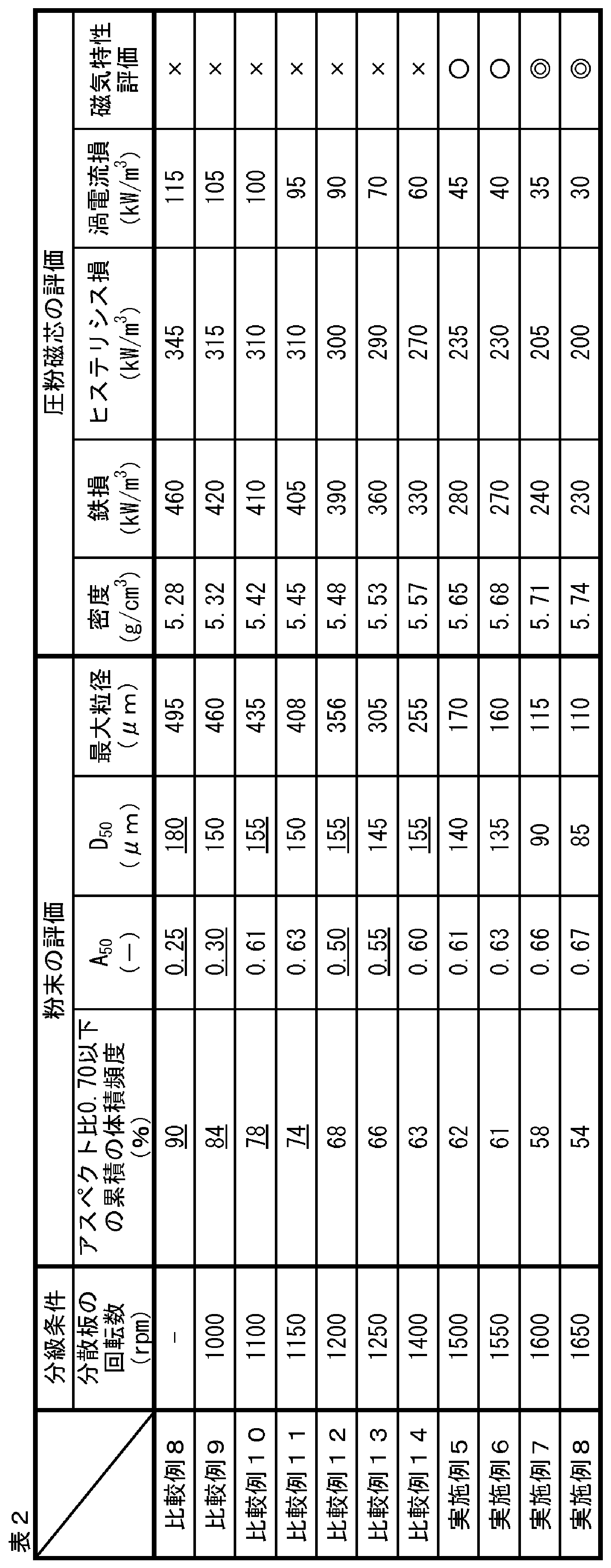
- Table 2 shows the classification conditions, powder evaluation, and dust core for comparative examples and examples using a soft magnetic alloy amorphous powder of Fe 81.6 Si 5 B 5 P 7.5 Cu 0.4 Ni 0.5. The evaluation of the core is shown.
- the iron loss of the powder magnetic core is 300 kW / m 3 or less, and it can be seen that the used powder is excellent as the iron-based powder for the powder magnetic core. Focusing on the hysteresis loss and the eddy current loss with respect to the iron loss, the examples were both low and excellent as compared with the comparative examples.
- the powder magnetic core using the iron-based powder for the powder magnetic core of the present invention has low iron loss and high insulating properties, and is highly useful.
Landscapes
- Engineering & Computer Science (AREA)
- Chemical & Material Sciences (AREA)
- Power Engineering (AREA)
- Mechanical Engineering (AREA)
- Organic Chemistry (AREA)
- Metallurgy (AREA)
- Materials Engineering (AREA)
- Dispersion Chemistry (AREA)
- Manufacturing & Machinery (AREA)
- Physics & Mathematics (AREA)
- Electromagnetism (AREA)
- Crystallography & Structural Chemistry (AREA)
- Nanotechnology (AREA)
- Powder Metallurgy (AREA)
- Soft Magnetic Materials (AREA)
Abstract
Description
例えば、特許文献1には、粒子のアスペクト比(ここでは、長軸径/短軸径)の平均値が1以上3以下の非晶質合金粒子を使用することで、比較的球形に近いため圧粉成形された際の充填率が高くなり、飽和磁束密度の高い圧粉磁芯を得ることができることが開示されている。
特許文献2にも粒子のアスペクト比(ここでは、長軸径/短軸径)が1.0を超え2.6以下のナノ結晶軟磁性合金粒子を使用することで高周波領域でのコア損失を低減していることが開示されている。
前記圧粉磁芯用鉄基粉末を構成する粒子の累積の体積頻度で算出した粒径の中央値が150μm以下であり、
前記粒子のアスペクト比0.70以下の累積の体積頻度が70%以下であり、かつ累積の体積頻度で算出したアスペクト比の中央値が0.60以上である、
圧粉磁芯用鉄基粉末。
[2]前記粒子の最大粒径が500μm以下である、[1]の圧粉磁芯用鉄基粉末。
[3]不可避的不純物を除く成分組成が、組成式:FeaSibBcPdCueMf
(式中、
79at%≦a≦84.5at%、
0at%≦b<6at%、
0at%<c≦10at%、
4at%<d≦11at%、
0.2at%≦e≦1.0at%、
0at%≦f≦4at%、かつ
a+b+c+d+e+f=100at%であり、
Mは、Nb、Mo、Ni、Sn、Zr、Ta、W、Hf、Ti、V、Cr、Mn、C、Al、S、OおよびNからなる群から選ばれる少なくとも1種の元素である)
で示される軟磁性粉末からなる、[1]または[2]の圧粉磁芯用鉄基粉末。
[4]前記圧粉磁芯用鉄基粉末を構成する粒子の表面に絶縁被覆を有する、[1]~[3]のいずれかの圧粉磁芯用鉄基粉末。
[5][1]~[4]のいずれかの圧粉磁芯用鉄基粉末の加圧成形体である圧粉磁芯。
[6][1]~[4]のいずれかの圧粉磁芯用鉄基粉末を金型に装入し、加圧成形する工程を含む、圧粉磁芯の製造方法。
本発明の圧粉磁芯用鉄基粉末においては、アスペクト比が極端に低い粒子の割合が少なく、かつアスペクト比の中央値が大きいため、1粒子内における磁壁のピンニングサイトとなりうる粒子表面の凹凸が減少しており、磁壁移動が容易である。これにより保磁力が低減するためヒステリシス損が減少する。
また、粉末粒子が高アスペクト比を有するため、圧粉体における粉末粒子の絶縁被覆の破壊が低減し、粉末粒子間の導通も減少するため、渦電流損が減少する。さらに、高アスペクト比の粉末粒子は流動性が高く、圧粉磁芯を作製する際の金型への充填性を向上させ、加圧成形による圧粉成形時にも粉体内での粒子の再配列を促進する一方、金型と粒子間の摩擦を低減させる。そのため、金型壁面における粉体の移動も容易となって圧密しやすく、密度の高い圧粉磁芯が作製可能である。圧粉密度の増加により鉄損の低減が達成できる。
本発明の一実施形態である圧粉磁芯用鉄基粉末(以下、「鉄基粉末」ともいう。)は、構成する粒子の累積の体積頻度で算出した粒径の中央値が150μm以下であり、前記粒子のアスペクト比0.70以下の累積の体積頻度が70%以下であり、かつ累積の体積頻度で算出したアスペクト比の中央値が0.60以上である。ここで、「鉄基粉末」とは、50質量%以上のFeを含む金属粉末を指すものとする。
本発明の鉄基粉末は、構成する粒子の累積の体積頻度で算出した粒径の中央値D50が150μm以下である。粒径の中央値D50が上記上限値以下の細粒とした方が粉体の流動性が高くなり、金型への充填密度が向上し、ひいては圧粉磁芯の密度が向上し、鉄損を十分に低減することができる。また、細粒は、渦電流損を小さくすることができ、この点からも鉄損の低減化に有利である。粒径の中央値D50は、好ましくは100μm以下である。一方、粒径の中央値D50は、粉末に均一な樹脂被覆を行う点から、3μm以上とすることができ、好ましくは5μm以上である。
粒径の測定は、対象となる粉末を、溶媒(例えば、エタノール)中に投入し、30秒以上の超音波振動により分散させて、レーザー回折・散乱法を用いたレーザー回折式粒度分布測定機により粒子の体積基準の粒度分布を測定する。得られた粒度分布から累積粒度分布を算出し、全粒子の体積の総和の50%に相当する粒子の粒径を中央値D50として、該当粉末の粒径の代表値として用いる。
本発明でいうアスペクト比(A)は、下記(1)式で定義される値とする。
A=W/L ・・・ (1)
(ここで、
Aは、アスペクト比であり、
Wは、1粒子の短軸径であり、単位はmであり、
Lは、1粒子の長軸径であり、単位はmである。)
測定対象とする粉末を、例えば圧縮空気で、平坦な表面(例えば、ガラス板の表面)上に分散させて、各粒子の画像を顕微鏡で撮影する。測定対象の粉末における全粒子数は1000個以上とする。
撮影画像をコンピュータで解析し、各粒子の投影像について、投影面積、短軸径と長軸径を測定する。長軸径は粒子の投影像においてとりうる最大の長さであり、短軸径はその最大長さに直交する方向の最大長さである。測定結果を上記(1)式に代入して、各粒子のアスペクト比を算出する。
各粒子の投影面積と同じ面積を持つ円の直径(円相当径)を算出し、その直径と同じ直径を有する球の体積を算出する。これにより、各粒子のアスペクト比と体積が得られ、各アスペクト比における体積頻度を算出することができ、アスペクト比0.70以下の粒子の累積の体積頻度(体積割合)を求めることができる。
本発明の鉄基粉末は、最大粒径が500μm以下であることが好ましい。最大粒径を500μm以下とすることで、粉末粒子全体の粒径がある程度均一化するほど、粒径の近い粒子同士が近くに集まるといった粒子の偏析の防止や粗大粒子表面に付着する微細粒子の数が減少し、粗大粒子が作る粒子間の隙間に細粒が入り込むようになるため圧粉磁芯の高密度化や高強度化ができ、低鉄損化につながる。一方、粉末に均一な樹脂被覆を行う点から、最大粒径は10μm以上とすることができる。最大粒径は、レーザー回折式粒度分布測定機により測定した際の粒度分布の最大値であり、測定条件は、上記のD50の測定と同様である。粒子の均一化の点から、最大粒径はD50の2倍以下であることが好ましく、1.5倍以下であることがさらに好ましい。
本発明の鉄基粉末は、不可避的不純物を除く成分組成が、
組成式:FeaSibBcPdCueMf
(式中、
79at%≦a≦84.5at%、
0at%≦b<6at%、
0at%<c≦10at%、
4at%<d≦11at%、
0.2at%≦e≦1.0at%、
0at%≦f≦4at%、
a+b+c+d+e+f=100at%であり、
Mは、Nb、Mo、Ni、Sn、Zr、Ta、W、Hf、Ti、V、Cr、Mn、C、Al、S、OおよびNからなる群から選ばれる少なくとも1種の元素である)
で示される軟磁性粉末からなることが好ましい。このような組成とすることにより、粉末の結晶化度を10%以下に抑えることができ、熱処理後によって、bccFeのナノ結晶を析出させて磁性特性を一層改善することができる。
軟磁性粉末は、製造工程等から不可避的に混入される不可避的不純物が含まれ得るが、上記組成式は、不可避的不純物を除いたものである。
本発明の鉄基粉末は、金属溶湯に水やガスを吹き付け、噴霧状にして冷却凝固させる水アトマイズ法やガスアトマイズ法を用いて製造することができる。あるいは、粉砕法や酸化物還元法で得られた粉末を加工することによって得ることもできる。
水アトマイズ法やガスアトマイズ法を用いる場合、水やガスを吹き付けるガスを低圧に調整することにより、アスペクト比を所定の範囲とすることができる。あるいは、アスペクト比の調整は、粒子表面の平滑化や、篩での分級で円形度の低い粒子を除去することで行うこともできる。例えば、粉砕法や酸化物還元法、または通常の高圧での水アトマイズ法やガスアトマイズ法で得られた粉末の粒子表面を平滑化するか、および/または篩での分級によりアスペクト比の低い粒子を除去して、本発明の鉄基粉末を得ることもできる。
本発明の圧粉磁芯用鉄基粉末は、該圧粉磁芯用鉄基粉末を構成する粒子の表面に絶縁被覆を備えることができる。
無機絶縁被覆としては、アルミニウム化合物を含有する被膜が好ましく、リン酸アルミニウムを含有する被膜がより好ましい。無機絶縁被覆は、化成皮膜であっても。
有機絶縁被覆としては、有機樹脂被膜が好ましい。有機樹脂被膜としては、例えば、シリコーン樹脂、フェノール樹脂、エポキシ樹脂、ポリアミド樹脂、ポリイミド樹脂などが挙げられる。これらを単独で含んでいても、2種以上を任意の比率で含んでいてもよい。中でも、シリコーン樹脂を含有する被膜がより好ましい。
絶縁被覆は、1層の被膜であっても、2層以上からなる多層被膜であってもよい。多層被膜は、同種の被膜からなる多層被膜であっても、異なる種類の被膜からなる多層被膜であってもよい。
アルミニウム化合物を含有する被覆は、アルミニウム化合物を主体とする被膜であってよく、アルミニウム化合物からなる被膜であってもよい。被膜は、さらにアルミニウム以外の金属を含む金属化合物を含有してもよい。アルミニウム以外の金属としては、例えば、Mg、Mn、Zn、Co、Ti、Sn、Ni、Fe、Zr、Sr、Y、Cu、Ca、V、Baなどが挙げられる。これらは単独で用いても、2種以上を任意の比率で用いてもよい。アルミニウム以外の金属を含む金属化合物としては、例えば、リン酸塩、炭酸塩、硝酸塩、酢酸塩、および水酸化物などが挙げられる。これらは単独で用いても、2種以上を任意の比率で用いてもよい。金属化合物は、水などの溶媒に可溶であることが好ましく、水溶性金属塩であることがより好ましい。
ここで、被覆量は、以下の式で定義される値を指すものとする。
被覆量(質量%)=(絶縁被覆の質量)/(圧粉磁芯用鉄基粉末のうち、絶縁被覆を除く部分の質量)×100
混合方法は、特に限定されないが、アトライターまたはヘンシェルミキサーなどの槽内で鉄基粉末と処理溶液とを撹拌混合する方法、転動流動型被覆装置等により鉄基粉末を流動状態として処理溶液を供給して混合する方法などが好ましい。
鉄基粉末への溶液の供給は、混合開始前または開始直後に全量を供給してもよく、混合中に数回に分けて供給してもよい。あるいは、液滴供給装置、スプレーなどを用いて、混合中に継続して処理液を供給してもよい。
処理液の供給は、特に限定されないが、スプレーを用いて行うことが好ましい。スプレーを用いることにより、処理溶液を鉄基粉末全体に均一に散布でき、また、噴霧条件を調整して、噴霧液滴の直径を10μm程度以下まで小さくすることができ、その結果、被覆が過剰に厚くなることを防止でき、均一かつ薄い絶縁被覆を鉄基粉末に容易に形成できるからである。一方、流動造粒機、転動造粒機などの流動槽、またはヘンシェルミキサーのような撹拌型混合機によって撹拌混合を行うこともでき、これらは粉体同士の凝集が抑制されるという利点を有する。鉄基粉末へのより均一な絶縁被覆の形成の点からは、流動槽や撹拌型混合機と、スプレーによる処理溶液の供給とを組み合わせることが好ましい。混合器中または混合後に加熱処理を施すことが、溶媒の乾燥促進や、反応の促進の点から有利である。
本発明の他の実施形態である圧粉磁芯は、上記圧粉磁芯用鉄基粉末を用いてなる圧粉磁芯である。
圧粉磁芯の製造方法は、特に限定されず、任意の方法を用いることができる。例えば、本発明の鉄基粉末を金型に装入し、所望の寸法および形状となるように加圧成形することによって圧粉磁芯を得ることができる。鉄基粉末は絶縁被膜を備えたものであることが好ましい。
成形圧力は、用途に応じて適宜決定することができるが、成形圧力を増加すれば、圧粉密度が高くなり、磁気特性が向上する点から、490MPa以上が好ましく、より好ましくは686MPa以上である。
潤滑剤は、特に限定されず、ステアリン酸リチウム、ステアリン酸亜鉛、ステアリン酸カルシウムなどの金属石鹸、脂肪酸アミド等のワックスが挙げられる。
組成がFe81.3Si3B9P6Cu0.7である軟磁性合金アモルファス粉末と組成がFe81.6Si5B5P7.5Cu0.4Ni0.5である軟磁性合金アモルファス粉末を水アトマイズ法による急冷凝固より製造した。製造した粉末から真空乾燥により乾燥粉末を得た。
乾燥粉末を分級して粒径とアスペクト比の調整を実施した。分級には気流分級機(株式会社セイシン企業製、ラボクラッシールN-01)を使用し、分散板を1000~1650rpmの速度で回転させて分級した。また、比較用の粉末(比較例1および8)として、気流分級機による分級を実施せずに水アトマイズ法のみで作製した粉末を準備した。
乾燥粉末をガラス面の上に分散させて、顕微鏡(スペクトリス株式会社製、モフォロギG3)により1試料あたり5000個の粒子を観察および撮影した。顕微鏡には倍率10倍のレンズを用いた。算出したアスペクト比と体積頻度からアスペクト比0.70以下の粒子の累積の体積頻度(体積割合)と粉末粒子全体のアスペクト比の代表値である中央値A50を算出した。また、乾燥粉末の粒径と体積頻度をレーザー回折式粒度分布測定機(株式会社堀場製作所製、LA-950V2)を用いて、溶媒のエタノール中に軟磁性合金アモルファス粉末を投入して1分間の超音波振動による分散後に測定した。粒径と体積頻度から粉末粒子全体の粒径の代表値である中央値D50を算出した。最大粒径は、レーザー回折式粒度分布測定機により測定した際の粒度分布の最大値である。
軟磁性合金アモルファス粉末に絶縁被覆用溶液の添加および混合により絶縁被覆を施し、被覆粉末とした。使用した溶液はシリコーンレジン樹脂分60質量%をキシレンの添加により希釈した溶液であり、軟磁性合金アモルファス粉末に対する樹脂が3質量%となる量で用いた。混合後、乾燥のため10時間大気雰囲気下で静置した。乾燥後、樹脂硬化のため150℃で60分間の熱処理を行った。
次に、これら被覆軟磁性合金アモルファス粉末を、ステアリン酸リチウムを塗布した金型に充填し、加圧成形して圧粉磁芯(外径38mmφ×内径25mmφ×高さ6mm)とした。成形圧力は1470MPaとし、1回で成形した。成形体の強度向上のためN2雰囲気下の炉で室温から3℃/分で昇温後に400℃で20分間熱処理した。熱処理後はN2雰囲気下で炉から取り出してから室温まで空冷し、得られた試料を圧粉磁芯とした。
得られた圧粉磁芯それぞれの圧粉密度を求めた。前記圧粉密度は、圧粉磁芯の質量を測定し、該質量を、圧粉磁芯の寸法から算出した体積で割ることにより算出した。
作製した圧粉磁芯に一次側:100ターン、二次側:20ターンを巻いて測定用試料とした。直流磁化特性試験装置(メトロン技研株式会社製、SK-110型)を用いて最大磁束密度0.1T、50Hzでヒステリシスループを書き、面積をヒステリシス損とした。測定したヒステリシス損を400倍して、磁束密度0.1T、周波数20kHzにおけるヒステリシス損を算出した。また、高周波鉄損測定装置(メトロン技研株式会社製)を用いて、0.1T、20kHzでの鉄損を測定した。測定した鉄損と上記のヒステリシス損の差を渦電流損として算出した。
磁気特性評価は以下のとおりである。
鉄損が250kW/m3以下・・・◎
鉄損が300kW/m3以下250kW/m3超・・・〇
鉄損が300kW/m3超・・・×

鉄損に関し、ヒステリシス損と渦電流損に着目すると、実施例は比較例と比較していずれも低く優れていた。これは実施例の粉末の方がアスペクト比0.70以下の低アスペクト比の粒子が少なく、かつ粉末全体のアスペクト比を示すA50も高く、球状に近い粒子が多いことにより、粒子の保磁力が低くなったためヒステリシス損が低下し、また、圧粉磁芯とした際の粒子表面の絶縁被覆の破壊も少なくなったため、粒子間の渦電流損が低下したことによるものといえる。
中でも、アスペクト比0.70以下の累積の体積頻度(体積割合)が60%以下、A50が0.65以上、D50が100μm以下の粉末を使用した実施例3および4では、圧粉磁芯の鉄損が250kW/m3以下であり、使用した粉末は、圧粉磁芯用鉄基粉末として、一層優れていることがわかる。
鉄損に関し、ヒステリシス損と渦電流損に着目すると、実施例は比較例と比較していずれも低く優れていた。これは実施例の粉末の方がアスペクト比0.70以下の低アスペクト比の粒子が少なく、かつ粉末全体のアスペクト比を示すA50も高く、球状に近い粒子が多いことにより、粒子の保磁力が低くなったためヒステリシス損が低下し、また、圧粉磁芯とした際の粒子表面の絶縁被覆の破壊も少なくなったため、粒子間の渦電流損が低下したことによるものといえる。
中でも、アスペクト比0.70以下の累積の体積頻度(体積割合)が60%以下、A50が0.65以上、D50が100μm以下の粉末を使用した実施例7および8では、圧粉磁芯の鉄損が250kW/m3以下であり、使用した粉末は、圧粉磁芯用鉄基粉末として、一層優れていることがわかる。
Claims (6)
- 圧粉磁芯用鉄基粉末であって、
前記圧粉磁芯用鉄基粉末を構成する粒子の累積の体積頻度で算出した粒径の中央値が150μm以下であり、
前記粒子のアスペクト比0.70以下の累積の体積頻度が70%以下であり、かつ累積の体積頻度で算出したアスペクト比の中央値が0.60以上である、
圧粉磁芯用鉄基粉末。 - 前記粒子の最大粒径が500μm以下である、請求項1に記載の圧粉磁芯用鉄基粉末。
- 不可避的不純物を除く成分組成が、組成式:FeaSibBcPdCueMf
(式中、
79at%≦a≦84.5at%、
0at%≦b<6at%、
0at%<c≦10at%、
4at%<d≦11at%、
0.2at%≦e≦1.0at%、
0at%≦f≦4at%、かつ
a+b+c+d+e+f=100at%であり、
Mは、Nb、Mo、Ni、Sn、Zr、Ta、W、Hf、Ti、V、Cr、Mn、C、Al、S、OおよびNからなる群から選ばれる少なくとも1種の元素である)
で示される軟磁性粉末からなる、請求項1または2に記載の圧粉磁芯用鉄基粉末。 - 前記圧粉磁芯用鉄基粉末を構成する粒子の表面に絶縁被覆を有する、請求項1~3のいずれか一項に記載の圧粉磁芯用鉄基粉末。
- 請求項1~4のいずれか一項に記載の圧粉磁芯用鉄基粉末の加圧成形体である圧粉磁芯。
- 請求項1~4のいずれか一項に記載の圧粉磁芯用鉄基粉末を金型に装入し、加圧成形する工程を含む、圧粉磁芯の製造方法。
Priority Applications (5)
| Application Number | Priority Date | Filing Date | Title |
|---|---|---|---|
| KR1020227042673A KR102938729B1 (ko) | 2020-06-19 | 2021-04-27 | 압분 자심용 철기 분말, 압분 자심 및 압분 자심의 제조 방법 |
| CN202180039257.6A CN115697588B (zh) | 2020-06-19 | 2021-04-27 | 压粉磁芯用铁基粉末、压粉磁芯和压粉磁芯的制造方法 |
| JP2021539383A JP7207551B2 (ja) | 2020-06-19 | 2021-04-27 | 圧粉磁芯用鉄基粉末、圧粉磁芯および圧粉磁芯の製造方法 |
| US18/000,288 US20230290552A1 (en) | 2020-06-19 | 2021-04-27 | Iron-based powder for dust core, dust core, and method of manufacturing dust core |
| EP21826313.5A EP4169638A4 (en) | 2020-06-19 | 2021-04-27 | IRON-BASED POWDER FOR A DUST CORE, DUST CORE AND METHOD FOR PRODUCING A DUST CORE |
Applications Claiming Priority (2)
| Application Number | Priority Date | Filing Date | Title |
|---|---|---|---|
| JP2020-106588 | 2020-06-19 | ||
| JP2020106588 | 2020-06-19 |
Publications (1)
| Publication Number | Publication Date |
|---|---|
| WO2021256097A1 true WO2021256097A1 (ja) | 2021-12-23 |
Family
ID=79267836
Family Applications (1)
| Application Number | Title | Priority Date | Filing Date |
|---|---|---|---|
| PCT/JP2021/016849 Ceased WO2021256097A1 (ja) | 2020-06-19 | 2021-04-27 | 圧粉磁芯用鉄基粉末、圧粉磁芯および圧粉磁芯の製造方法 |
Country Status (6)
| Country | Link |
|---|---|
| US (1) | US20230290552A1 (ja) |
| EP (1) | EP4169638A4 (ja) |
| JP (1) | JP7207551B2 (ja) |
| KR (1) | KR102938729B1 (ja) |
| CN (1) | CN115697588B (ja) |
| WO (1) | WO2021256097A1 (ja) |
Citations (6)
| Publication number | Priority date | Publication date | Assignee | Title |
|---|---|---|---|---|
| JP2002356708A (ja) * | 2001-05-30 | 2002-12-13 | Tdk Corp | 磁性金属粉末の製造方法および磁性金属粉末 |
| JP2010212442A (ja) * | 2009-03-10 | 2010-09-24 | Nec Tokin Corp | 非晶質軟磁性粉末、トロイダルコアおよびインダクタ |
| JP2015167183A (ja) | 2014-03-04 | 2015-09-24 | Necトーキン株式会社 | ナノ結晶軟磁性合金粉末およびそれを用いた圧粉磁芯 |
| JP2016015357A (ja) | 2014-06-30 | 2016-01-28 | セイコーエプソン株式会社 | 非晶質合金粉末、圧粉磁心、磁性素子および電子機器 |
| WO2017022227A1 (ja) * | 2015-07-31 | 2017-02-09 | Jfeスチール株式会社 | 軟磁性圧粉磁芯の製造方法および軟磁性圧粉磁芯 |
| WO2019031464A1 (ja) * | 2017-08-07 | 2019-02-14 | 日立金属株式会社 | 結晶質Fe基合金粉末及びその製造方法 |
Family Cites Families (8)
| Publication number | Priority date | Publication date | Assignee | Title |
|---|---|---|---|---|
| JP3771224B2 (ja) * | 2002-09-11 | 2006-04-26 | アルプス電気株式会社 | 非晶質軟磁性合金粉末及びそれを用いた圧粉コア及び電波吸収体 |
| JP6514461B2 (ja) * | 2013-10-01 | 2019-05-15 | 日東電工株式会社 | 軟磁性粒子粉末、軟磁性樹脂組成物、軟磁性フィルム、軟磁性フィルム積層回路基板および位置検出装置 |
| JP2016003366A (ja) * | 2014-06-17 | 2016-01-12 | Necトーキン株式会社 | 軟磁性合金粉末並びにそれを用いた圧粉磁芯及びその製造方法 |
| JP6898057B2 (ja) * | 2015-07-31 | 2021-07-07 | 株式会社トーキン | 圧粉磁心 |
| JP6648856B2 (ja) * | 2017-08-07 | 2020-02-14 | 日立金属株式会社 | Fe基合金、結晶質Fe基合金アトマイズ粉末、及び磁心 |
| US11854725B2 (en) * | 2017-11-16 | 2023-12-26 | Tdk Corporation | Soft magnetic metal powder, method for producing the same, and soft magnetic metal dust core |
| EP3831975B1 (en) * | 2018-07-31 | 2022-07-06 | JFE Steel Corporation | Soft magnetic powder |
| JP7529595B2 (ja) * | 2021-03-10 | 2024-08-06 | 株式会社トーキン | 圧粉磁心、インダクタ、及び圧粉磁心の製造方法 |
-
2021
- 2021-04-27 US US18/000,288 patent/US20230290552A1/en active Pending
- 2021-04-27 EP EP21826313.5A patent/EP4169638A4/en active Pending
- 2021-04-27 CN CN202180039257.6A patent/CN115697588B/zh active Active
- 2021-04-27 WO PCT/JP2021/016849 patent/WO2021256097A1/ja not_active Ceased
- 2021-04-27 KR KR1020227042673A patent/KR102938729B1/ko active Active
- 2021-04-27 JP JP2021539383A patent/JP7207551B2/ja active Active
Patent Citations (6)
| Publication number | Priority date | Publication date | Assignee | Title |
|---|---|---|---|---|
| JP2002356708A (ja) * | 2001-05-30 | 2002-12-13 | Tdk Corp | 磁性金属粉末の製造方法および磁性金属粉末 |
| JP2010212442A (ja) * | 2009-03-10 | 2010-09-24 | Nec Tokin Corp | 非晶質軟磁性粉末、トロイダルコアおよびインダクタ |
| JP2015167183A (ja) | 2014-03-04 | 2015-09-24 | Necトーキン株式会社 | ナノ結晶軟磁性合金粉末およびそれを用いた圧粉磁芯 |
| JP2016015357A (ja) | 2014-06-30 | 2016-01-28 | セイコーエプソン株式会社 | 非晶質合金粉末、圧粉磁心、磁性素子および電子機器 |
| WO2017022227A1 (ja) * | 2015-07-31 | 2017-02-09 | Jfeスチール株式会社 | 軟磁性圧粉磁芯の製造方法および軟磁性圧粉磁芯 |
| WO2019031464A1 (ja) * | 2017-08-07 | 2019-02-14 | 日立金属株式会社 | 結晶質Fe基合金粉末及びその製造方法 |
Non-Patent Citations (1)
| Title |
|---|
| See also references of EP4169638A4 |
Also Published As
| Publication number | Publication date |
|---|---|
| EP4169638A4 (en) | 2023-11-15 |
| CN115697588B (zh) | 2026-01-16 |
| US20230290552A1 (en) | 2023-09-14 |
| CN115697588A (zh) | 2023-02-03 |
| KR20230006906A (ko) | 2023-01-11 |
| JPWO2021256097A1 (ja) | 2021-12-23 |
| KR102938729B1 (ko) | 2026-03-12 |
| EP4169638A1 (en) | 2023-04-26 |
| JP7207551B2 (ja) | 2023-01-18 |
Similar Documents
| Publication | Publication Date | Title |
|---|---|---|
| CN112534076B (zh) | 软磁性粉末、Fe基纳米晶合金粉末、磁性部件以及压粉磁芯 | |
| WO2008093430A1 (ja) | 高圧縮性鉄粉、およびそれを用いた圧粉磁芯用鉄粉と圧粉磁芯 | |
| KR20150123217A (ko) | 철-기반 금속 유리로 만들어진 분말 | |
| JP7569641B2 (ja) | 磁気コア、磁性部品および電子機器 | |
| JP2019178402A (ja) | 軟磁性粉末 | |
| CN108570214B (zh) | 压粉磁芯 | |
| US11804317B2 (en) | Soft magnetic metal powder and electronic component | |
| JP2007092162A (ja) | 高圧縮性鉄粉、およびそれを用いた圧粉磁芯用鉄粉と圧粉磁芯 | |
| JP7304498B2 (ja) | 鉄基軟磁性粉末、それを用いた磁性部品及び圧粉磁芯 | |
| JP2022001659A (ja) | 圧粉磁芯用鉄基粉末およびそれを用いた圧粉磁芯 | |
| KR102528358B1 (ko) | 압분 자심용 철기 분말 및 압분 자심 | |
| JP7207551B2 (ja) | 圧粉磁芯用鉄基粉末、圧粉磁芯および圧粉磁芯の製造方法 | |
| CN119724807A (zh) | 软磁性金属粉末、磁芯及磁性部件 | |
| JP2007231330A (ja) | 圧粉磁心用金属粉末および圧粉磁心の製造方法 | |
| CA3223549C (en) | Iron-based soft magnetic powder, magnetic component using same and dust core | |
| WO2023007900A1 (ja) | Fe基非晶質合金粉末、磁性部品、および圧粉磁芯 | |
| WO2023007901A1 (ja) | Fe基非晶質合金粉末、磁性部品、および圧粉磁芯 | |
| JP2025167784A (ja) | 軟磁性合金粒子、軟磁性粉末、圧粉磁芯および電子部品 | |
| JP2003257722A (ja) | 軟磁性粉末、それを用いた圧粉磁心 | |
| JP2004172469A (ja) | 軟磁性粉末とその製造方法 |
Legal Events
| Date | Code | Title | Description |
|---|---|---|---|
| ENP | Entry into the national phase |
Ref document number: 2021539383 Country of ref document: JP Kind code of ref document: A |
|
| 121 | Ep: the epo has been informed by wipo that ep was designated in this application |
Ref document number: 21826313 Country of ref document: EP Kind code of ref document: A1 |
|
| ENP | Entry into the national phase |
Ref document number: 20227042673 Country of ref document: KR Kind code of ref document: A |
|
| ENP | Entry into the national phase |
Ref document number: 2021826313 Country of ref document: EP Effective date: 20230119 |
|
| NENP | Non-entry into the national phase |
Ref country code: DE |