WO2022003921A1 - 振動アクチュエータ - Google Patents
振動アクチュエータ Download PDFInfo
- Publication number
- WO2022003921A1 WO2022003921A1 PCT/JP2020/026096 JP2020026096W WO2022003921A1 WO 2022003921 A1 WO2022003921 A1 WO 2022003921A1 JP 2020026096 W JP2020026096 W JP 2020026096W WO 2022003921 A1 WO2022003921 A1 WO 2022003921A1
- Authority
- WO
- WIPO (PCT)
- Prior art keywords
- vibration
- yoke
- pair
- length
- mover
- Prior art date
- Legal status (The legal status is an assumption and is not a legal conclusion. Google has not performed a legal analysis and makes no representation as to the accuracy of the status listed.)
- Ceased
Links
Images



Classifications
-
- B—PERFORMING OPERATIONS; TRANSPORTING
- B06—GENERATING OR TRANSMITTING MECHANICAL VIBRATIONS IN GENERAL
- B06B—METHODS OR APPARATUS FOR GENERATING OR TRANSMITTING MECHANICAL VIBRATIONS OF INFRASONIC, SONIC, OR ULTRASONIC FREQUENCY, e.g. FOR PERFORMING MECHANICAL WORK IN GENERAL
- B06B1/00—Methods or apparatus for generating mechanical vibrations of infrasonic, sonic, or ultrasonic frequency
- B06B1/02—Methods or apparatus for generating mechanical vibrations of infrasonic, sonic, or ultrasonic frequency making use of electrical energy
- B06B1/04—Methods or apparatus for generating mechanical vibrations of infrasonic, sonic, or ultrasonic frequency making use of electrical energy operating with electromagnetism
- B06B1/045—Methods or apparatus for generating mechanical vibrations of infrasonic, sonic, or ultrasonic frequency making use of electrical energy operating with electromagnetism using vibrating magnet, armature or coil system
-
- H—ELECTRICITY
- H02—GENERATION; CONVERSION OR DISTRIBUTION OF ELECTRIC POWER
- H02K—DYNAMO-ELECTRIC MACHINES
- H02K33/00—Motors with reciprocating, oscillating or vibrating magnet, armature or coil system
- H02K33/16—Motors with reciprocating, oscillating or vibrating magnet, armature or coil system with polarised armatures moving in alternate directions by reversal or energisation of a single coil system
Definitions
- the present invention relates to a vibration actuator.
- vibration notification method using a vibration actuator (or vibration motor) as a method of notifying a person of an incoming call or an alarm.
- vibration actuators have been used as a directing effect of action scenes and as one of feedback means to players, and people are used by vibration. Reality is improved by stimulating the sense of touch.
- the vibration actuator of Patent Document 1 has a structure in which a mover (movable body referred to in Patent Document 1) including a weight or the like is electrically reciprocated, and the mover is supported by a leaf spring in a case. There is.
- the vibration actuator is required to be further miniaturized in order to improve the mountability on a small device.
- a driving force for generating sufficient vibration is also required, and a vibration actuator capable of miniaturization and generating sufficient driving force is desired.
- the present invention has been made to solve such a problem, and an object of the present invention is to provide a vibration actuator capable of generating a sufficient vibration driving force while realizing miniaturization. It is in.
- the vibration actuator according to the present invention has a case made of a non-magnetic material, a tubular electromagnetic drive portion provided inside the case, and a radial inside of the electromagnetic drive portion.
- the movable element is provided and has a mover that is vibrably supported along the vibration axis and a pair of leaf springs that support one end and the other end of the mover in the direction of the vibration axis.
- the child is composed of a magnet, a pair of pole pieces made of a soft magnetic material having the magnet sandwiched from both sides along the vibration axis, and a non-magnetic material having the pair of pole pieces sandwiched from both sides along the vibration axis.
- the electromagnetic drive unit has a pair of weights, and the electromagnetic drive unit is arranged at intervals along the vibration axis, and each of the pair of coils formed in a tubular shape and the pair of coils are radially outside. It has a tubular yoke made of a soft magnetic material that is arranged and is formed so as to project outward in the vibration axis direction from the pair of coils, and the average length of the yoke in the vibration axis direction is The length from one end to the other end of the pair of pole pieces is equal to or greater than the length obtained by adding twice the amplitude of one side in the vibration of the mover.
- the average length of the yoke in the vibration axis direction is the length from one end to the other end of the pair of pole pieces, plus four times the amplitude. It may be as follows.
- the inner diameter of the yoke may be 1.3 times or less the outer diameter of the pole piece.
- the inner diameter of the yoke may be 1.2 times or more the outer diameter of the pole piece.
- the center position of each of the pair of coils in the vibration axis direction is outside the center position of the pole pieces on the same side of the pair of pole pieces during non-vibration. There may be.
- the yoke has one or a plurality of notches formed on each of the one-side edge and the other-side edge in the vibration axis direction, and the notch on one side edge of the yoke is formed.
- the total notch area of the other side edge may be the same as the total notch area of the notch portion of the other side edge.
- the vibration actuator according to the present invention using the above means, it is possible to generate a sufficient driving force of vibration while realizing miniaturization.
- FIG. 1 is an exploded perspective view of the vibration actuator according to the embodiment of the present invention
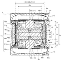
- FIG. 2 is a vertical cross-sectional view of the vibration actuator
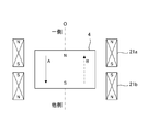
- FIG. 3 is a diagram illustrating the operation of the vibration actuator
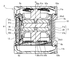
- FIG. 4A is a mover on one side in the vibration axis direction
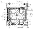
- 4B is a cross-sectional view of the state in which the actuator is moved
- FIG. 4B is a cross-sectional view of the state in which the actuator is moved to the other side in the vibration axis direction.
- the configuration of the vibration actuator will be described based on these figures.
- the vibration actuator 1 mainly includes a cylindrical case 2 forming an outer shell, a case-side electromagnetic drive unit 3 provided inside the case 2, and a mover 4 that can be vibrated by the case-side electromagnetic drive unit 3. It is composed of a first leaf spring 5a and a second leaf spring 5b that elastically support both ends of the mover 4.
- the vibration actuator 1 is mounted on, for example, a mobile terminal such as a mobile phone or a smartphone, a controller of a game machine, or the like.
- the case 2 has a cylindrical case body 10, a first cover case 11a, and a second cover case 11b, and both open ends of the case body 10 are closed by the first cover case 11a and the second cover case 11b.
- the case body 10, the first cover case 11a, and the second cover case 11b are each made of a resin material such as ABS.
- a terminal 12 to which a lead wire (not shown) is connected is formed on the outer surface of the case body 10.
- the case-side electromagnetic drive unit 3 has a yoke 20 and a pair of coils 21a and 21b.
- the mover 4 has a magnet 30 (magnet) and a pair of pole pieces 31a and 31b.
- the yoke 20 made of a cylindrical soft magnetic material is attached along the inner circumference of the case 2, and the first coil 21a and the first coil 21a attached to the inner circumference of the yoke 20 in a state of being electrically insulated from the yoke 20.
- Two coils 21b and the like are provided.
- the first coil 21a and the second coil 21b are wound along the inner circumference of the yoke 20.
- the first coil 21a and the second coil 21b can generate a magnetic field by energization from the terminal 12, respectively.
- the first coil 21a and the second coil 21b may be fixed to the yoke 20, the first inner guide 6a, and the second inner guide 6b with an adhesive or the like.
- the first coil 21a and the second coil 21b surround the mover 4 at a distance from the mover 4.
- the mover 4 is arranged to vibrate along the vibration axis O (axial direction of the case 2).
- the mover 4 includes a disk-shaped magnet 30, a disk-shaped first pole piece 31a and a second pole piece 31b arranged so as to sandwich the magnet 30, and these magnets 30, the first pole piece 31a, and the like. It has a first mass (weight, weight) 32a and a second mass (weight, weight) 32b arranged so as to sandwich the second pole piece 31b.
- the magnetizing direction of the magnet 30 is the vibration axis O direction.
- the first pole piece 31a and the second pole piece 31b are made of a soft magnetic material, and are attached to the magnet 30 by the magnetic attraction force of the magnet 30 and an adhesive or the like.
- the first pole piece 31a and the second pole piece 31b are integrated by inserting the central protrusions 32a1 and 32b1 of the first mass 32a and the second mass 32b into the through holes 31a1 and 31b1 formed in the central portions, respectively. There is.
- the magnet 30, the first pole piece 31a, the second pole piece 31b, the first square 32a, and the second square 32b constituting the mover 4 are integrated.
- the integration of the magnet 30, the first pole piece 31a, the second pole piece 31b, the first mass 32a, and the second mass 32b is not limited to the above-mentioned magnetic attraction and attachment by an adhesive. , It may be integrated by fixing by mechanical means such as screwing or other means.
- the first mass 32a and the second mass 32b are made of a non-magnetic material, and the vibration axis O is formed from the columnar portions 32a2 and 32b2 extending in the vibration axis O direction and the root portions (center side in the vibration axis O direction) of the columnar portions 32a2 and 32b2. It is composed of bottomed cylindrical portions 32a3 and 32b3 having a U-shaped cross section that extends in the vertical direction (hereinafter referred to as radial direction) and opens outward in the O direction of the vibration axis.
- both ends in the vibration axis O direction that is, the tip portions 32a4 and 32b4 of the first mass 32a and the second mass 32b, respectively, are formed by the first leaf spring 5a and the second leaf spring 5b. It is supported.
- Elastic members are provided on one surface of the first leaf spring 5a and the second leaf spring 5b, respectively.
- the first leaf spring 5a and the second leaf spring 5b are connected to the first mass 32a and the second mass 32b of the mover 4 via the holes 50a and 50b formed in the central support portions 51a and 51b, respectively.
- first leaf spring 5a and the second leaf spring 5b a plurality of arm portions 52a and 52b spirally extend from the central support portions 51a and 51b to the outer periphery and are connected to the annular frame portions 53a and 53b, respectively.
- the frame portions 53a and 53b of the first leaf spring 5a and the second leaf spring 5b are connected to the case body 10.
- the first leaf spring 5a and the second leaf spring 5b are composed of one or a plurality of metal leaf springs.
- a thin plate of stainless steel (spring material) is processed. ..
- the material of the first leaf spring 5a and the second leaf spring 5b is not limited to metal, but may be a composite material containing resin or fiber. Further, the materials of the first leaf spring 5a and the second leaf spring 5b are preferably materials that are resistant to fatigue and have excellent flexibility. Further, the first leaf spring 5a and the second leaf spring 5b are provided with an elastic member, and the deformation of the elastic member suppresses the vibration of each of the leaf springs 5a and 5b.
- the first leaf spring 5a and the second leaf spring 5b configured in this way can be elastically deformed within a predetermined range in the crossing direction including the vibration axis O direction and the vertical radial direction orthogonal to the vibration axis O.
- this predetermined range corresponds to the amplitude range of the mover 4 when normally used as the vibration actuator 1. Therefore, the predetermined range is at least a range in which the first leaf spring 5a and the second leaf spring 5b do not come into contact with the case 2, and a range in which the limit of elastic deformation of the first leaf spring 5a and the second leaf spring 5b is not exceeded. Is.
- the first inner guide 6a is provided on one side of the vibration actuator 1 in the vibration axis O direction, and is provided on the other side (case 2 center side) of the vibration axis O direction with respect to the first leaf spring 5a.
- the second inner guide 6b is on the other side of the vibration actuator 1 in the vibration axis O direction, and is provided on one side (center side of the case 2) in the vibration axis O direction with respect to the second leaf spring 5b. That is, the first inner guide 6a and the second inner guide 6b are provided in the case 2 on the center side in the vibration axis O direction with respect to the first leaf spring 5a and the second leaf spring 5b.
- the first inner guide 6a and the second inner guide 6b are made of a resin material such as ABS. However, the materials of the first inner guide 6a and the second inner guide 6b are not limited to the resin material.
- the vibration actuator 1 configured as described above has the first leaf spring 5a and the second leaf spring as shown in FIG.
- the mover 4 supported by the 5b is located at the center of the first coil 21a and the second coil 21b.
- the first coil 21a and the second coil 21b are energized with alternating current in a direction in which a magnetic field of opposite polarity is generated via the terminal 12. That is, the same pole is generated in the adjacent portions of the first coil 21a and the second coil 21b.
- a thrust force is generated in the mover 4 toward the other side (downward in FIG. 3) in the vibration axis O direction indicated by the solid arrow A, and flows to the first coil 21a and the second coil 21b.
- a thrust is generated in the mover 4 in the direction of the vibration axis O indicated by the dotted arrow B (upward in FIG. 3).
- the mover 4 receives the thrust by the electromagnetic force and the restoring force by the leaf springs 5a and 5b, and vibrates along the vibration axis O. do.
- the thrust generated in the mover 4 is basically based on the thrust given based on Fleming's left-hand rule.
- the first coil 21a and the second coil 21b are fixed to the case 2, the reaction of the force generated in the first coil 21a and the second coil 21b to the mover 4 to which the magnet 30 and the like are attached. Thrust as a force is generated.
- the yoke 20 increases the horizontal component of the magnetic flux of the magnet 30.
- the second pole piece 31b on the other side is the first coil 21a on one side. It is displaced to the position where a part of it overlaps.
- the first pole piece 31a on one side is displaced to a position where a part of the first pole piece 31a on the other side overlaps with the second coil 21b on the other side.
- the first leaf spring 5a and the second leaf spring 5b are elastically deformed within a predetermined range in the vibration axis O direction and the radial direction, and the mover 4 and the first leaf spring 5a and the second leaf spring 5a and the second.
- the leaf spring 5b does not come into contact with the first inner guide 6a and the second inner guide 6b.
- the mover 4 excessively oscillates outward in the vibration axis O direction as compared with FIGS. 4A and 4B, and the first leaf spring 5a and the second leaf spring When the 5b moves beyond a predetermined range, the first leaf spring 5a or the second leaf spring 5b comes into contact with the first inner guide 6a or the second inner guide 6b. As a result, the mover 4 is restricted from moving further to one side in the vibration axis O direction, and the mover 4 is prevented from coming into contact with the case 2 (first cover case 11a).
- the mover 4 when a radial impact is applied to the case 2, the mover 4 also moves in the radial direction. In such a case, when the mover 4 moves in the radial direction and the first leaf spring 5a and the second leaf spring 5b move beyond a predetermined range in the radial direction, the first leaf spring 5a and the second leaf spring 5a and the second leaf spring 5b move. 5b comes into contact with the first inner guide 6a and the second inner guide 6b.
- FIG. 5 is a perspective view of the yoke
- FIG. 6 is a graph of the relationship between the yoke length and the force coefficient.
- the dimensional relationship of each part of the vibration actuator of the present embodiment will be described with reference to FIGS. 5 and 6 and FIG. 2 described above.
- the average length Ly of the yoke 20 has a length Lp from one end to the other end of the pair of pole pieces 31a and 31b, and the mover 4 has a mover 4. It is the length (Lp + 2La) or more, which is the sum of the length twice the amplitude La on one side in vibration.
- the yoke 20 is formed with a plurality of notches 70 for arranging wiring and other parts at both end edges in the vibration axis O direction.
- the yoke 20 of the present embodiment has notches 70 formed as rectangular recesses at three locations on one side edge and three locations on the other side edge.
- the notch depth of each notch 70 is the same, but the length of the notch in the circumferential direction is different.
- the length in the vibration axis O direction differs depending on the position in the circumferential direction. For example, as shown in FIG.
- the length Lya in the vibration axis O direction at the position where the notch 70 is formed on both one side edge and the other side edge is short.
- the length Lyb in the vibration axis O direction at the position where the notch 70 is formed on one side edge or the other end edge is longer than Lya, and the notch 70 is formed on one side edge and the other end edge.
- the length Lyc in the vibration axis O direction at the position not set is longer than Lyb.
- each notch 70 on one side edge of the yoke 20 and the total notch area of each notch 70 on the other end edge match. That is, the average length on one side and the average length on the other side coincide with each other from the center position of the yoke 20 in the vibration axis O direction. As a result, even in the yoke 20 having the notch 70, the driving force for vibrating the mover 4 is not biased between one side and the other side in the vibration axis O direction, and stable vibration can be realized.
- the shape and number of the cutouts are not limited to this, and the plurality of cutouts may have different shapes.
- the total matching of the notch area of each notch 70 on one side edge of the yoke 20 and the total notch area of each notch 70 on the other end edge is not limited to perfect matching, and is not limited to perfect matching, and is in the vibration axis O direction. It suffices that the magnetic fluxes generated from the yoke 20 on one side and the other side are substantially the same as long as they do not cause a large bias.
- the length Lp from one end to the other end of the pair of pole pieces 31a and 31b is the length of the magnet 30, the first pole piece 31a, and the second pole piece 31b in the mover 4 in the vibration axis O direction. It corresponds to the length of the magnetic material portion of the mover 4.
- Amplitude La is the fluctuation range of the mover 4 from the non-vibration (equilibrium state) position to one side in the vibration axis O direction during vibration. That is, the length twice the amplitude La corresponds to the fluctuation width of the mover 4 from the non-vibration position to both sides of the vibration axis O direction during vibration.
- the average length Ly of the yoke 20 By setting the average length Ly of the yoke 20 to be equal to or greater than the length Lp from one end to the other end of the pair of pole pieces 31a and 31b plus a length twice the amplitude La (Lp + 2La). Even during the vibration of the mover 4, the magnetic material portion (magnet 30 and pole pieces 31a, 31b) of the mover 4 is always within the range of the yoke 20. In other words, even when the mover 4 vibrates, the magnetic material portion does not exceed both end edges of the yoke 20.
- the minimum length Lya of the yoke 20 in the vibration axis O direction is a length (Lp + 2La) obtained by adding a length twice the amplitude La to the length Lp from one end to the other end of the pair of pole pieces 31a and 31b. ) It may be more than that. By doing so, even during the vibration of the mover 4, the magnetic material portion of the mover 4 is more reliably contained within the range of the yoke 20.
- FIG. 6 shows the reduction rate of the force coefficient BL according to the yoke length when the yoke length is shortened with reference to the first force coefficient BL1 of the first yoke length Ly1 which is sufficiently long with respect to the length Lp.
- the graph is shown. It should be noted that each value shown in FIG. 6 is a simulation result obtained by using a vibration actuator having a size substantially the same as that of the vibration actuator 1 of the present embodiment and having a simplified notch portion of the yoke removed as a model.
- the force coefficient BL is a numerical value obtained by multiplying the horizontal component of the magnetic flux density in the magnetic gap composed of the pole piece and the yoke by the effective line length of the coil wire.
- the force coefficient BL is a parameter corresponding to the driving force of vibration in the vibration actuator.
- a sufficiently long first yoke length Ly1 is a yoke length at which the increase in the force coefficient BL begins to saturate as the yoke length is lengthened, for example, from one end to the other end of a pair of pole pieces.
- the length (Lp + 4La) obtained by adding the length up to Lp to 4 times the amplitude La corresponds to the length (Lp + 4La) obtained by adding the length up to Lp to 4 times the amplitude La.
- the force coefficient BL tends to decrease as the yoke length is shortened from the first yoke length Ly1.
- the second yoke length Ly2 in FIG. 6 is a length (Lp + 2La) obtained by adding a length of twice the amplitude La to the length Lp from one end to the other end of the pair of pole pieces.
- the reduction rate of the force coefficient BL decreases more than -3%, and the degree of decrease rate of the force coefficient BL with respect to the decrease of the yoke length also increases. That is, it can be said that the second yoke length Ly2 corresponds to the inflection point of the reduction rate of the force coefficient BL.
- the length of the yoke is made longer than the length (Lp + 2La) obtained by adding the length Lp from one end to the other end of at least one pair of pole pieces and twice the amplitude La. Even when the length is shorter than the first yoke length Ly1, a sufficient force coefficient can be secured, and the vibration actuator 1 can generate a sufficient driving force. Further, the length of the yoke is shorter than the length (Lp + 2La) obtained by adding the length Lp from one end to the other end of the pair of pole pieces plus four times the amplitude La, so that the vibration actuator can be made smaller. It is possible to secure a sufficient driving force while trying to improve the quality.
- the inner diameter Dy of the yoke 20 is 1.3 times or less the outer diameter Dp of each of the pole pieces 31a and 31b.
- FIG. 7 is a table showing the relationship of the force coefficient BL in the vibration actuator model (hereinafter, simply referred to as a model) in which the pole piece outer diameter Dp, the yoke inner diameter Dy, and the magnet outer diameter Dm are changed.
- FIG. 8 is a graph showing the reduction rate of the force coefficient from the first yoke length Ly1 to the second yoke length Ly2 in each model of FIG. 7. In FIGS. 7 and 8, the simulation is performed with the first yoke length Ly1 being 16 mm and the second yoke length Ly2 being 10.5 mm.
- FIG. 7 the model No. of each vibration actuator model is shown.
- Areas A1 to A4 in FIG. 8 feature points, pole piece outer diameter Dp, yoke inner diameter Dy, yoke inner diameter / pole piece outer diameter (Dy / Dp), second yoke length Ly2 is 10.5 mm.
- the force coefficient BL2 and the first yoke length Ly1 are 16.0 mm
- the force coefficient reduction rate from the first force coefficient BL1 and the first force coefficient BL1 to the second force coefficient BL2 (hereinafter, simply referred to as the force coefficient reduction rate).
- the force coefficient reduction rate are shown respectively.
- each model can be roughly classified into areas A1 to A4 according to the tendency.
- Area A1 model No. No. 1 has a yoke inner diameter / pole piece outer diameter of 1.338, which is higher than other models, a magnet outer diameter Dm, which is smaller than other models, and a force coefficient reduction rate of -4.80%. The degree of decrease is larger than that.
- Area A2 model No. 2-No. 10, No. 13 has different magnet outer diameter Dm and pole piece outer diameter Dp, but the yoke inner diameter / pole piece outer diameter is in the range of 1.2 to 1.3, and the force coefficient reduction rate is -3.0% in each case. The degree of decrease is smaller than that.
- the force coefficient reduction rate is smaller than -3.0%, but the yoke inner diameter / pole piece outer diameter is as low as 1.170. That is, since the outer diameter Dp of the pole piece is large and the gap with the coil is narrow, for example, in the configuration of the above embodiment, the pole pieces 31a and 31b may interfere with the inner guides 6a and 6b.
- Area A4 model No. 14 is characterized in that the yoke inner diameter Dy is larger than that of other models, but the yoke inner diameter / pole piece outer diameter is 1.315, which is larger than that of other models, and the force coefficient reduction rate is also -3. The degree of decrease is relatively large at 94%.
- the force coefficient reduction rate can be suppressed to a smaller degree than -3.0% in the range where the yoke inner diameter / pole piece outer diameter including the areas A2 and A3 is 1.3 or less. ..
- the force coefficient BL sharply decreases (the reduction rate increases).
- the gap between the coil and the pole piece can be reduced to some extent even if the size is reduced in the radial direction.
- the vibration actuator can be downsized and sufficient driving force can be generated. Further, by setting the inner diameter of the yoke to 1.2 times or more the outer diameter of the pole piece, sufficient durability can be ensured.
- the center positions Mc1 and Mc2 of the pair of coils 21a and 21b in the vibration axis O direction are a pair of pole pieces in a non-vibration state (in a balanced state). It is outside the vibration axis direction from the center positions Mp1 and Mp2 of the pole pieces 31a and 31b on the same side of 31a and 31b.
- the center position Mc1 of the coil 21a on the one side in the vibration axis O direction is on the one side in the vibration axis O direction with respect to the center position Mp1 of the pole piece 31a on the one side in the vibration axis O direction.
- center position Mc2 of the second coil 21b on the other side in the vibration axis O direction is on the other side in the vibration axis O direction than the center position Mp2 of the pole piece 31b on the other side in the vibration axis O direction.
- the magnetic flux from the pole pieces 31a and 31b to the coils 21a and 21b is not only in the radial direction but also in the vibration axis O direction as shown by the white arrows in FIG. Partially diffuse.
- the spread of this magnetic flux is larger on the outside in the vibration axis O direction than on the inside (center side) in the vibration axis O direction.
- the coils 21a and 21b may receive more such diffused magnetic flux. can. This makes it possible to improve the driving force of the mover 4 when it vibrates.
Landscapes
- Engineering & Computer Science (AREA)
- Power Engineering (AREA)
- Physics & Mathematics (AREA)
- Electromagnetism (AREA)
- Mechanical Engineering (AREA)
- Reciprocating, Oscillating Or Vibrating Motors (AREA)
- Apparatuses For Generation Of Mechanical Vibrations (AREA)
Abstract
Description
以上のように構成された振動アクチュエータ1は、第1コイル21a及び第2コイル21bに通電していない状態(平衡状態)では、図2に示すように、第1板ばね5a及び第2板ばね5bで支持される可動子4は、第1コイル21a及び第2コイル21bの中央に位置している。
図5は、ヨークの斜視図であり、図6はヨーク長さと力係数との関係のグラフである。以下、これら図5、図6と上述の図2に基づき本実施形態の振動アクチュエータの各部の寸法関係について説明する。
図2及び図7に示すように、本実施形態の振動アクチュエータ1は、ヨーク20の内径Dyが各ポールピース31a、31bの外径Dpの1.3倍以下である。
図2に示すように、本実施形態の振動アクチュエータ1は、一対のコイル21a、21bのそれぞれの振動軸O方向の中心位置Mc1、Mc2は、非振動時(平衡状態時)の一対のポールピース31a、31bのうち同じ側にあるポールピース31a、31bの中心位置Mp1、Mp2よりも振動軸方向外側である。具体的には、振動軸O方向一側のコイル21aの中心位置Mc1は、振動軸O方向一側のポールピース31aの中心位置Mp1よりも振動軸O方向一側にある。また、振動軸O方向他側の第2コイル21bの中心位置Mc2は、振動軸O方向他側のポールピース31bの中心位置Mp2よりも振動軸O方向他側にある。
2 ケース
3 ケース側電磁駆動部
4 可動子
5a 第1板ばね
5b 第2板ばね
6a 第1インナーガイド
6b 第2インナーガイド
20 ヨーク
21a 第1コイル
21b 第2コイル
30 マグネット(磁石)
31a 第1ポールピース
31b 第2ポールピース
32a 第1マス(錘)
32b 第2マス(錘)
Claims (6)
- 非磁性材料からなるケースと、
該ケースの内部に設けられた筒状の電磁駆動部と、
該電磁駆動部の径方向内側に設けられ、振動軸に沿って振動可能に支持された可動子と、
前記振動軸方向における前記可動子の一端部と他端部とをそれぞれ支持する一対の板ばねと、を有し、
前記可動子は、磁石と、該磁石を前記振動軸に沿って両側から挟んだ軟磁性材料からなる一対のポールピースと、該一対のポールピースを前記振動軸に沿って両側から挟んだ非磁性材料からなる一対の錘と、を有し、
前記電磁駆動部は、前記振動軸に沿って間隔をおいて配置され、それぞれ筒状に形成された一対のコイルと、前記一対のコイルの径方向外側に配置され、該一対のコイルよりも前記振動軸方向の外方に突出して形成された軟磁性材料からなる筒状のヨークと、を有し、
前記振動軸方向において、前記ヨークの平均長さが、前記一対のポールピースの一端部から他端部までの長さに、前記可動子の振動における片側の振幅の2倍の長さを加えた長さ以上である
ことを特徴とする振動アクチュエータ。 - 前記振動軸方向において、前記ヨークの平均長さが前記一対のポールピースの一端部から他端部までの長さに、前記振幅の4倍の長さを加えた長さ以下である
請求項1記載の振動アクチュエータ。 - 前記ヨークの内径は、前記ポールピースの外径の1.3倍以下である
請求項1又は2に記載の振動アクチュエータ。 - 前記ヨークの内径は、前記ポールピースの外径の1.2倍以上である
請求項3に記載の振動アクチュエータ。 - 前記一対のコイルのそれぞれの振動軸方向の中心位置は、非振動時の前記一対のポールピースのうち同じ側にあるポールピースの中心位置よりも振動軸方向外側である
請求項1から4のいずれか一項に記載の振動アクチュエータ。 - 前記ヨークは前記振動軸方向の一側端縁及び他側端縁のそれぞれに1又は複数の切欠部が形成されており、前記ヨークの一側端縁の切欠部の切欠面積の合計と、他側端縁の切欠部の切欠面積の合計が一致する、
請求項1から5のいずれか一項に記載の振動アクチュエータ。
Priority Applications (5)
| Application Number | Priority Date | Filing Date | Title |
|---|---|---|---|
| US18/003,795 US12294272B2 (en) | 2020-07-02 | 2020-07-02 | Oscillatory actuator |
| CN202080102226.6A CN115702047A (zh) | 2020-07-02 | 2020-07-02 | 振动致动器 |
| EP20942689.9A EP4163019B1 (en) | 2020-07-02 | 2020-07-02 | Oscillatory actuator |
| PCT/JP2020/026096 WO2022003921A1 (ja) | 2020-07-02 | 2020-07-02 | 振動アクチュエータ |
| JP2021537174A JP7217810B2 (ja) | 2020-07-02 | 2020-07-02 | 振動アクチュエータ |
Applications Claiming Priority (1)
| Application Number | Priority Date | Filing Date | Title |
|---|---|---|---|
| PCT/JP2020/026096 WO2022003921A1 (ja) | 2020-07-02 | 2020-07-02 | 振動アクチュエータ |
Publications (1)
| Publication Number | Publication Date |
|---|---|
| WO2022003921A1 true WO2022003921A1 (ja) | 2022-01-06 |
Family
ID=79314957
Family Applications (1)
| Application Number | Title | Priority Date | Filing Date |
|---|---|---|---|
| PCT/JP2020/026096 Ceased WO2022003921A1 (ja) | 2020-07-02 | 2020-07-02 | 振動アクチュエータ |
Country Status (5)
| Country | Link |
|---|---|
| US (1) | US12294272B2 (ja) |
| EP (1) | EP4163019B1 (ja) |
| JP (1) | JP7217810B2 (ja) |
| CN (1) | CN115702047A (ja) |
| WO (1) | WO2022003921A1 (ja) |
Cited By (1)
| Publication number | Priority date | Publication date | Assignee | Title |
|---|---|---|---|---|
| EP4501472A4 (en) * | 2022-03-29 | 2026-03-18 | Hamanakodenso Co Ltd | VIBRATION DEVICE |
Families Citing this family (1)
| Publication number | Priority date | Publication date | Assignee | Title |
|---|---|---|---|---|
| JP7560326B2 (ja) * | 2020-11-10 | 2024-10-02 | フォスター電機株式会社 | 振動アクチュエータ |
Citations (5)
| Publication number | Priority date | Publication date | Assignee | Title |
|---|---|---|---|---|
| JP2006007161A (ja) * | 2004-06-29 | 2006-01-12 | Namiki Precision Jewel Co Ltd | 振動リニアアクチュエータ |
| JP2013223334A (ja) * | 2012-04-16 | 2013-10-28 | Nihon Densan Seimitsu Kk | 振動発生装置 |
| JP2019170118A (ja) | 2018-03-26 | 2019-10-03 | ミツミ電機株式会社 | 振動アクチュエータ及び電子機器 |
| WO2020045470A1 (ja) * | 2018-08-28 | 2020-03-05 | ミネベアミツミ株式会社 | 振動アクチュエータ及び電子機器 |
| JP2020054018A (ja) * | 2018-09-21 | 2020-04-02 | フォスター電機株式会社 | 振動アクチュエータ |
Family Cites Families (7)
| Publication number | Priority date | Publication date | Assignee | Title |
|---|---|---|---|---|
| JP2003181376A (ja) * | 2001-12-21 | 2003-07-02 | Matsushita Electric Ind Co Ltd | 振動リニアアクチュエータ |
| JP2004266903A (ja) * | 2003-02-28 | 2004-09-24 | Matsushita Electric Ind Co Ltd | リニア振動アクチュエータ |
| JP2006043573A (ja) * | 2004-08-04 | 2006-02-16 | Tokyo Parts Ind Co Ltd | 扁平型振動モータを内蔵させた電磁音響変換器。 |
| US20130169071A1 (en) * | 2010-06-30 | 2013-07-04 | Nidec Copal Corporation | Oscillating actuator |
| JP5842789B2 (ja) * | 2012-11-01 | 2016-01-13 | ミツミ電機株式会社 | アクチュエータ及び電動理美容器具 |
| JP7116293B2 (ja) * | 2017-11-17 | 2022-08-10 | ミツミ電機株式会社 | 振動アクチュエーター及び携帯機器 |
| JP7311693B2 (ja) * | 2020-09-16 | 2023-07-19 | フォスター電機株式会社 | 振動アクチュエータ |
-
2020
- 2020-07-02 US US18/003,795 patent/US12294272B2/en active Active
- 2020-07-02 EP EP20942689.9A patent/EP4163019B1/en active Active
- 2020-07-02 CN CN202080102226.6A patent/CN115702047A/zh active Pending
- 2020-07-02 WO PCT/JP2020/026096 patent/WO2022003921A1/ja not_active Ceased
- 2020-07-02 JP JP2021537174A patent/JP7217810B2/ja active Active
Patent Citations (5)
| Publication number | Priority date | Publication date | Assignee | Title |
|---|---|---|---|---|
| JP2006007161A (ja) * | 2004-06-29 | 2006-01-12 | Namiki Precision Jewel Co Ltd | 振動リニアアクチュエータ |
| JP2013223334A (ja) * | 2012-04-16 | 2013-10-28 | Nihon Densan Seimitsu Kk | 振動発生装置 |
| JP2019170118A (ja) | 2018-03-26 | 2019-10-03 | ミツミ電機株式会社 | 振動アクチュエータ及び電子機器 |
| WO2020045470A1 (ja) * | 2018-08-28 | 2020-03-05 | ミネベアミツミ株式会社 | 振動アクチュエータ及び電子機器 |
| JP2020054018A (ja) * | 2018-09-21 | 2020-04-02 | フォスター電機株式会社 | 振動アクチュエータ |
Cited By (1)
| Publication number | Priority date | Publication date | Assignee | Title |
|---|---|---|---|---|
| EP4501472A4 (en) * | 2022-03-29 | 2026-03-18 | Hamanakodenso Co Ltd | VIBRATION DEVICE |
Also Published As
| Publication number | Publication date |
|---|---|
| EP4163019B1 (en) | 2025-01-22 |
| EP4163019A1 (en) | 2023-04-12 |
| US20230336064A1 (en) | 2023-10-19 |
| EP4163019A4 (en) | 2023-07-05 |
| CN115702047A (zh) | 2023-02-14 |
| US12294272B2 (en) | 2025-05-06 |
| JPWO2022003921A1 (ja) | 2022-01-06 |
| JP7217810B2 (ja) | 2023-02-03 |
Similar Documents
| Publication | Publication Date | Title |
|---|---|---|
| JP7188851B2 (ja) | 振動アクチュエータ、及びこれを備える携帯型電子機器 | |
| JP7313159B2 (ja) | 振動アクチュエータ | |
| CN112805909B (zh) | 振动致动器 | |
| CN101944818A (zh) | 线性振动器 | |
| WO2019098249A1 (ja) | 振動発生装置 | |
| JP2019201486A (ja) | リニア振動モータ及び電子機器 | |
| WO2017057314A1 (ja) | リニア振動モータ | |
| JP7217810B2 (ja) | 振動アクチュエータ | |
| WO2016114383A1 (ja) | リニア振動モータ | |
| JP7726518B2 (ja) | 振動アクチュエーター | |
| JP2017221905A (ja) | リニア振動モータ | |
| JP7664696B2 (ja) | 振動アクチュエータ | |
| JP7275089B2 (ja) | 振動アクチュエータ | |
| JP7560326B2 (ja) | 振動アクチュエータ | |
| JP6333186B2 (ja) | リニア振動モータ | |
| CN114337180A (zh) | 振动致动器和电子设备 | |
| JP7101604B2 (ja) | 振動アクチュエータ | |
| JP7540272B2 (ja) | 振動アクチュエーター及び電子機器 | |
| KR20220015006A (ko) | 진동 발생 장치 | |
| JP2019193511A (ja) | リニア振動モータ及び電子機器 | |
| JP6333187B2 (ja) | リニア振動モータ | |
| KR20100006718A (ko) | 진동 발생 장치 | |
| JP2022072473A (ja) | 振動アクチュエータ | |
| CN117650679A (zh) | 线性振动马达 | |
| KR20180009601A (ko) | 진동 발생 장치 |
Legal Events
| Date | Code | Title | Description |
|---|---|---|---|
| ENP | Entry into the national phase |
Ref document number: 2021537174 Country of ref document: JP Kind code of ref document: A |
|
| 121 | Ep: the epo has been informed by wipo that ep was designated in this application |
Ref document number: 20942689 Country of ref document: EP Kind code of ref document: A1 |
|
| ENP | Entry into the national phase |
Ref document number: 2020942689 Country of ref document: EP Effective date: 20230106 |
|
| NENP | Non-entry into the national phase |
Ref country code: DE |
|
| WWG | Wipo information: grant in national office |
Ref document number: 18003795 Country of ref document: US |