WO2022004064A1 - 自動分析装置 - Google Patents
自動分析装置 Download PDFInfo
- Publication number
- WO2022004064A1 WO2022004064A1 PCT/JP2021/009794 JP2021009794W WO2022004064A1 WO 2022004064 A1 WO2022004064 A1 WO 2022004064A1 JP 2021009794 W JP2021009794 W JP 2021009794W WO 2022004064 A1 WO2022004064 A1 WO 2022004064A1
- Authority
- WO
- WIPO (PCT)
- Prior art keywords
- liquid
- buffer tank
- flow path
- pure water
- control unit
- Prior art date
- Legal status (The legal status is an assumption and is not a legal conclusion. Google has not performed a legal analysis and makes no representation as to the accuracy of the status listed.)
- Ceased
Links
Images


Classifications
-
- G—PHYSICS
- G01—MEASURING; TESTING
- G01N—INVESTIGATING OR ANALYSING MATERIALS BY DETERMINING THEIR CHEMICAL OR PHYSICAL PROPERTIES
- G01N35/00—Automatic analysis not limited to methods or materials provided for in any single one of groups G01N1/00 - G01N33/00; Handling materials therefor
- G01N35/00584—Control arrangements for automatic analysers
- G01N35/00594—Quality control, including calibration or testing of components of the analyser
- G01N35/00613—Quality control
-
- G—PHYSICS
- G01—MEASURING; TESTING
- G01N—INVESTIGATING OR ANALYSING MATERIALS BY DETERMINING THEIR CHEMICAL OR PHYSICAL PROPERTIES
- G01N35/00—Automatic analysis not limited to methods or materials provided for in any single one of groups G01N1/00 - G01N33/00; Handling materials therefor
- G01N35/10—Devices for transferring samples or any liquids to, in, or from, the analysis apparatus, e.g. suction devices, injection devices
- G01N35/1004—Cleaning sample transfer devices
-
- B—PERFORMING OPERATIONS; TRANSPORTING
- B01—PHYSICAL OR CHEMICAL PROCESSES OR APPARATUS IN GENERAL
- B01L—CHEMICAL OR PHYSICAL LABORATORY APPARATUS FOR GENERAL USE
- B01L3/00—Containers or dishes for laboratory use, e.g. laboratory glassware; Droppers
- B01L3/50—Containers for the purpose of retaining a material to be analysed, e.g. test tubes
-
- G—PHYSICS
- G01—MEASURING; TESTING
- G01N—INVESTIGATING OR ANALYSING MATERIALS BY DETERMINING THEIR CHEMICAL OR PHYSICAL PROPERTIES
- G01N35/00—Automatic analysis not limited to methods or materials provided for in any single one of groups G01N1/00 - G01N33/00; Handling materials therefor
- G01N35/00584—Control arrangements for automatic analysers
- G01N35/00594—Quality control, including calibration or testing of components of the analyser
- G01N35/00613—Quality control
- G01N35/00663—Quality control of consumables
-
- G—PHYSICS
- G01—MEASURING; TESTING
- G01N—INVESTIGATING OR ANALYSING MATERIALS BY DETERMINING THEIR CHEMICAL OR PHYSICAL PROPERTIES
- G01N35/00—Automatic analysis not limited to methods or materials provided for in any single one of groups G01N1/00 - G01N33/00; Handling materials therefor
- G01N35/10—Devices for transferring samples or any liquids to, in, or from, the analysis apparatus, e.g. suction devices, injection devices
Definitions
- the present invention relates to an automated analyzer that performs qualitative and quantitative analysis of samples such as blood and urine.
- Patent Document 1 describes self-controlled decompression between an electric pressurizing pump and a branch pipe. It is possible to arrange a valve and provide a direct acting solenoid valve and a fixed resistance pipe with a specific hole diameter and length in the pipe beyond the branch pipe so that water can be supplied instantly by opening and closing the solenoid valve. Has been described.
- An automatic analyzer that analyzes a specific component in a biological sample such as blood or urine uses a reagent whose optical characteristics change in response to the specific component or a reagent equipped with an index that specifically reacts with the specific component.
- This is a device that performs qualitative and quantitative analysis by reacting a sample with a reagent and measuring changes in the optical properties of the reaction solution, or by counting the number of labels in the reaction solution.
- pure water is used in processes such as washing the probe and diluting the reagent.
- the pure water to be used is generally stored in a buffer tank from a water supply facility, and then appropriately supplied to a destination based on the operating status of the analyzer.
- the pure water stored in the buffer tank is an environment in which germs can easily grow, but biofilms may be formed when germs grow in the buffer tank. Due to the generated biofilm or the like, the water supply may not be performed as designed, and in the worst case, the measurement result may be affected.
- the present invention provides an automatic analyzer capable of reducing the frequency of cleaning and reducing the maintenance work time of the operator by suppressing the growth of fungi in the buffer tank as compared with the conventional one.
- the present invention includes a plurality of means for solving the above problems, and to give an example thereof, the present invention includes an analysis module for analyzing a sample and a supply system for supplying a liquid to the analysis module, and the supply is provided.
- the system sends a buffer tank that temporarily stores the liquid supplied from the outside of the apparatus, a supply flow path that sends the liquid in the buffer tank to the analysis module, and the liquid in the buffer tank.
- the frequency of cleaning the buffer tank can be reduced as compared with the conventional case, and the maintenance work time of the operator can be reduced. Issues, configurations and effects other than those mentioned above will be clarified by the description of the following examples.
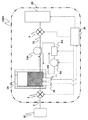
- FIG. 1 is a schematic view showing an overall configuration of an automated analyzer according to an embodiment of the present invention.
- the automatic analyzer 100 shown in FIG. 1 includes a solenoid valve 2, a buffer tank 3, a circulating water pump 4, a sterilization mechanism 5, a solenoid valve 6, a supply flow path 7, a circulation flow path 8, a water supply flow path 9, and a cleanliness measuring unit. 10.
- the liquid temperature measuring unit 11, the control unit 30, the analysis module 20, and the like are provided.
- the control unit 30 constitutes a supply system for supplying the liquid to the analysis module 20.
- the analysis module 20 is a module for performing qualitative and quantitative analysis of the components of the sample.
- the analysis items in the analysis module 20 are not particularly limited, and various analysis items such as biochemical items, immune items, and electrolyte items are targeted, and known configurations can be adopted as the configurations, but at least from the supply system. It includes a configuration that uses the supplied pure water (for example, a dispensing nozzle, a reaction vessel, a constant temperature bath).
- the buffer tank 3 is connected to the pure water production device 50 outside the device by the water supply flow path 9, and is a tank for temporarily storing the liquid supplied from the pure water production device 50, for example, pure water. Pure water is supplied from the pure water production device 50 to the buffer tank 3 when the solenoid valve 2 is opened by the open / close signal from the control unit 30.
- a water level gauge or the like can be provided in the buffer tank 3.
- the supply flow path 7 is a flow path connecting the buffer tank 3 and the analysis module 20 so as to send the pure water in the buffer tank 3 to the analysis module 20, and is configured to allow pure water to flow. ..
- the supply flow path 7 is provided with a circulating water pump 4, a sterilization mechanism 5, and a solenoid valve 6. Pure water discharged from the circulating water pump 4 when the solenoid valve 6 is opened by an open / close signal from the control unit 30 is supplied to the analysis module 20, and is discharged from the circulating water pump 4 when the solenoid valve 6 is closed. The entire amount of the pure water is returned to the buffer tank 3.
- the circulating water pump 4 is a pump for sending or circulating pure water in the buffer tank 3 to the analysis module 20.
- the circulation flow path 8 is branched from the branch portion 12 of the supply flow path 7, and is a flow path for returning a part of the pure water discharged from the circulating water pump 4 to the buffer tank 3.
- the sterilization mechanism 5 is a mechanism for sterilizing pure water flowing through the supply flow path 7, and is composed of an ultraviolet light source or the like.
- the sterilization mechanism 5 is installed on the downstream side of the circulating water pump 4 and on the upstream side of the branch portion 12 between the supply flow path 7 and the circulation flow path 8.
- the cleanliness measuring unit 10 is a device for measuring the cleanliness of pure water stored in the buffer tank 3, and is composed of, for example, a conductivity meter for measuring the conductivity of pure water.
- the cleanliness measuring unit 10 may measure the conductivity of pure water in the supply flow path 7 and the circulation flow path 8.
- the present invention is not limited to measuring the conductivity of pure water, and other means can be used.
- the liquid temperature measuring unit 11 is a thermometer for measuring the liquid temperature of pure water in the buffer tank 3.
- the liquid temperature measuring unit 11 may measure the liquid temperature of pure water in the supply flow path 7 or the circulation flow path 8.
- the control unit 30 is a part for controlling the operation of each device in the above-mentioned supply system.
- the control unit 30 may have a function for controlling the operation of the analysis module 20, or may be independent, and is not particularly limited.
- the control unit 30 can be realized by loading a program into a computer or FPGA (Field-Programmable Gate Array) equipped with a CPU, a memory, an interface, and the like, and executing the calculation. These programs are stored in an internal recording medium or an external recording medium (not shown) in each configuration, and are read and executed by the CPU.
- FPGA Field-Programmable Gate Array
- operation control process may be integrated into one program, each may be divided into a plurality of programs, or a combination thereof may be used. Further, a part or all of the program may be realized by dedicated hardware or may be modularized. Further, various programs may be installed in each device from a program distribution server, an internal recording medium, or an external recording medium.
- control unit 30 may drive the sterilization mechanism 5 when pure water is supplied from the outside to the buffer tank 3 or when pure water is supplied from the buffer tank 3 to the analysis module 20. desirable.
- the buffer tank 3 may be refilled with pure water and the analysis module 20 may be supplied with water at the same time. In this case as well, the sterilization mechanism 5 is driven.
- control unit 30 drives the sterilization mechanism 5 even during the start-up operation and the start-up operation of the automatic analyzer 100.
- control unit 30 operates the sterilization mechanism 5 when it detects a specific operation in the analysis module 20.
- specific operation include a case where a user such as a service person or a clinical laboratory engineer operates an input unit to input an instruction to execute the operation of the sterilization mechanism 5.
- control unit 30 can adjust the liquid feeding speed of the circulating water pump 4 based on the operation of the sterilization mechanism 5.
- control unit 30 controls the operation of the sterilization mechanism 5 based on the cleanliness of the pure water measured by the cleanliness measuring unit 10. For example, by operating the sterilization mechanism 5 when the cleanliness of pure water falls below a certain threshold value, it is possible to operate the sterilization mechanism 5 appropriately according to the supply water state and the operation state of the device.
- control unit 30 controls the operation of the sterilization mechanism 5 based on the liquid temperature of pure water measured by the liquid temperature measuring unit 11.
- the optimum growth temperature of oligotrophic bacteria is generally about 25 to 30 ° C. Therefore, by monitoring the temperature of the circulating water, the sterilization mechanism 5 is operated at the water temperature at which germs are likely to grow.
- FIG. 2 is a control flowchart of the sterilization operation at the time of water supply.
- step S11 when the automatic analyzer 100 is in the operating state (step S11), the control unit 30 operates the circulating water pump 4 (step S12).
- control unit 30 determines whether or not it is necessary to replenish the buffer tank 3 from the pure water production apparatus 50 (step S13). When it is determined that refilling water is necessary, the process proceeds to step S14.
- the control unit 30 opens the solenoid valve 2 for a predetermined time, starts refilling water, and operates the sterilization mechanism 5 (step S14).
- the sterilization mechanism 5 is stopped (step S17), and the process is returned to step S13.
- the sterilization mechanism 5 may be operated after a predetermined time has elapsed from the completion of water replenishment.
- step S13 determines whether or not refilling water is not necessary.
- step S15 determines whether or not it is necessary to supply water to the analysis module 20.
- control unit 30 opens the solenoid valve 6 for a predetermined time and operates the sterilization mechanism 5 (step S16). After the water supply is completed, the solenoid valve 6 is closed, the sterilization mechanism 5 is stopped (step S17), and the process is returned to step S13.
- step S15 when it is determined in step S15 that water supply is not necessary, the process is returned to step S13.
- FIG. 3 is a schematic view showing the overall configuration of another embodiment of the automated analyzer of the embodiment.
- the automatic analyzer 100A shown in FIG. 3 includes a solenoid valve 2, a buffer tank 3A, a circulating water pump 4A, a sterilization mechanism 5A, an electromagnetic valve 6, a supply flow path 7A, a circulation flow path 8A, a water supply flow path 9, and a cleanliness measuring unit. 10.
- the liquid temperature measuring unit 11, the liquid feeding pump 13A, the control unit 30, the analysis module 20, and the like are provided.
- the circulating water pump 4A and the sterilization mechanism 5A are provided in the circulation flow path 8A instead of the form in which the circulation flow path branches from the supply flow path as in the automatic analyzer 100 shown in FIG. All of the pure water discharged from the circulating water pump 4A is returned to the buffer tank 3A. Further, a liquid feed pump 13A is provided in a supply flow path 7A, which is a dedicated line for supplying pure water to be fed to the analysis module 20.
- FIG. 1 shows a form in which the sterilization mechanism 5 is installed on the downstream side of the circulating water pump 4 and on the upstream side of the branch portion 12 between the supply flow path 7 and the circulation flow path 8, but the buffer tank 3 is shown. Can be provided inside. Further, it can be provided between the buffer tank 3 and the circulating water pump 4 or on the circulation flow path 8. Further, although the case where an ultraviolet light source is used as the sterilization mechanism 5, various sterilization means other than the ultraviolet light source can be used. Similarly, although FIG. 3 shows a form in which the sterilization mechanism 5A is installed in the circulation flow path 8A, it can be provided in the buffer tank 3.
- the supply system may be arranged outside the housing of the automatic analyzer 100.
- the buffer tanks 3 and 3A for temporarily storing the pure water supplied from the pure water production apparatus 50 outside the apparatus and the pure water in the buffer tanks 3 and 3A are used.
- the supply flow paths 7 and 7A that send It has a circulation flow path 8 and 8A for returning to 3A, a sterilization mechanism 5 and 5A for sterilizing pure water in the supply system, and a control unit 30 for controlling the operation of each device in the supply system.
- the pure water stored in the buffer tanks 3, 3A will be repeatedly sterilized along with the circulation, and the propagation of various germs in the buffer tanks 3, 3A will occur.
- it can be significantly suppressed as compared with the conventional case, and the pure water in the circulatory system including the buffer tanks 3 and 3A can be kept clean even if the labor-intensive work such as cleaning is reduced as compared with the conventional case. Therefore, since the maintenance work time of the operator can be shortened and the sterilization can be repeated, the effect that the configuration of the sterilization mechanisms 5 and 5A can be completed with the minimum necessary specifications can be obtained. Further, since it is provided on a flow path having a small diameter, it is not necessary to use a buffer tank having a large output as compared with the case where a sterilization mechanism is provided in the buffer tanks 3 and 3A, and miniaturization can be achieved.
- the pure water supplied from the pure water production apparatus 50 should be sterilized at an early stage and then stored. It is possible to store pure water with higher cleanliness. In addition, sterilization can be performed only at the required timing, and restrictions on the extension of the life of the sterilization mechanisms 5 and 5A and continuous operation can be solved.
- the sterilization operation can be performed again when water is supplied to the analysis module 20 for cleaning. Pure water can be sent to the analysis module 20, and sterilization can be performed only at the required timing, which has the effect of extending the life of the sterilization mechanisms 5, 5A.
- the sterilization mechanisms 5 and 5A by driving the sterilization mechanisms 5 and 5A during the start-up operation of the automatic analyzers 100 and 100A, even if the interval of use of the automatic analyzers 100 and 100A becomes long, the pure water left in the circulation path. It can be used in the analysis module 20 after being sufficiently sterilized.
- the automatic analyzers 100 and 100A are in the down state, the circulating water pumps 4, 4A and the sterilization mechanisms 5, 5A do not operate, and pure water in the buffer tanks 3, 3A is left for a long time, causing germs.
- the sterilization mechanisms 5 and 5A by driving the sterilization mechanisms 5 and 5A during the start-up operation of the automatic analyzers 100 and 100A, the state at the start of leaving can be made clean and the circulation path can be cleaned. In addition to being able to keep the temperature low, the time required to obtain highly clean pure water after starting up the next device can be shortened.
- the sterilization efficiency in the sterilization mechanisms 5, 5A can be improved, and the circulation path can be kept cleaner. Can be maintained. In addition, it is possible to prevent the retention of pure water in the circulating water path.
- a cleanliness measuring unit 10 for measuring the cleanliness of pure water is further provided, and it is necessary to control the operation of the sterilization mechanisms 5 and 5A based on the cleanliness of the pure water measured by the cleanliness measuring unit 10.
- the sterilization can be performed only at the appropriate timing, the cleanliness in the circulation flow path can be maintained at a certain level or higher, and the life of the sterilization mechanisms 5 and 5A can be extended.
- a liquid temperature measuring unit 11 for measuring the liquid temperature of pure water is further provided, and the operation of the sterilization mechanisms 5 and 5A is controlled based on the liquid temperature of pure water measured by the liquid temperature measuring unit 11 to obtain the most. Since sterilization can be performed in an environment where various germs can easily propagate, more efficient sterilization can be performed, and it is possible to extend the service life and simplify measures for continuous operation.
- the sterilization operation can be performed at the timing requested by the user, which is convenient and maintainable for service personnel and the like. Can contribute to the improvement of.
- the circulation flow path 8 is branched from the supply flow path 7, and a part of the pure water discharged from the circulating water pump 4 is returned to the buffer tank 3, and the sterilization mechanism 5 supplies the supply flow path 7 out of the supply flow path 7.
- the sterilization mechanism 5 supplies the supply flow path 7 out of the supply flow path 7.
Landscapes
- Health & Medical Sciences (AREA)
- Chemical & Material Sciences (AREA)
- Analytical Chemistry (AREA)
- General Health & Medical Sciences (AREA)
- Immunology (AREA)
- Biochemistry (AREA)
- Life Sciences & Earth Sciences (AREA)
- General Physics & Mathematics (AREA)
- Physics & Mathematics (AREA)
- Pathology (AREA)
- Engineering & Computer Science (AREA)
- Quality & Reliability (AREA)
- Hematology (AREA)
- Clinical Laboratory Science (AREA)
- Chemical Kinetics & Catalysis (AREA)
- Automatic Analysis And Handling Materials Therefor (AREA)
Abstract
検体の分析を行う分析モジュール(20)と、分析モジュール(20)に液体を供給する供給系と、を備え、供給系は、装置外部の純水製造装置(50)から供給される純水を一時的に貯蔵するバッファタンク(3)と、バッファタンク(3)内の純水を分析モジュール(20)へ送る供給流路(7)と、バッファタンク(3)内の純水を送液する循環水ポンプ(4)と、循環水ポンプ(4)から吐出された純水をバッファタンク(3)へ戻す循環流路(8)と、供給系内の純水の殺菌を行う殺菌機構(5)と、供給系内の各機器の動作を制御する制御部(30)と、を有する。これにより、バッファタンクでの菌類の繁殖を従来に比べて抑制することで清掃の頻度を従来に比べて減らし、オペレータのメンテナンス作業時間を低減することができる自動分析装置を提供する。
Description
本発明は、血液や尿などの試料の定性・定量分析を行う自動分析装置に関する。
自動分析装置の洗浄槽やノズルによる注水機構に精製水を配管給水するのに好適な装置内部配管の一例として、特許文献1には、電動加圧ポンプと分岐管との間に自力制御形減圧弁を配設し、分岐管から先の配管には直動式電磁弁と特定の穴径・長さを有する固定抵抗管を設けて電磁弁の開閉により瞬時に給水される構造とすることが記載されている。
血液、尿等の生体サンプル中の特定成分の分析を行う自動分析装置は、特定成分と反応して光学的特性が変化する試薬や、特定成分と特異的に反応する指標を備えた試薬を用いて、検体と試薬とを反応させ、反応液の光学的特性の変化を測定すること、あるいは反応液中の標識の数をカウントすることにより、定性・定量分析を行う装置である。
このような自動分析装置では、プローブの洗浄や試薬の希釈等の工程で純水を使用する。使用される純水は、一般的に給水設備からバッファタンクに貯蔵された後、分析装置の稼働状況に基づき使用先に適宜供給される。
ここで、バッファタンクに貯蔵される純水は雑菌が繁殖しやすい環境であるが、バッファタンク内で雑菌が増殖した場合にバイオフィルムが生成されることがある。この生成されたバイオフィルム等により、給水が設計通りに実行されない事態が生じかねず、最悪の場合には測定結果に影響を受ける可能性がある。
そこで、バッファタンク内に雑菌を繁殖させずに清浄に保つために、従来は定期的にバッファタンク内を清掃していたが、作業に時間を要することからオペレータの負担となっている。
本発明は、バッファタンクでの菌類の繁殖を従来に比べて抑制することで清掃の頻度を従来に比べて減らし、オペレータのメンテナンス作業時間を低減することができる自動分析装置を提供する。
本発明は、上記課題を解決する手段を複数含んでいるが、その一例を挙げるならば、検体の分析を行う分析モジュールと、前記分析モジュールに液体を供給する供給系と、を備え、前記供給系は、装置外部から供給される前記液体を一時的に貯蔵するバッファタンクと、前記バッファタンク内の前記液体を前記分析モジュールへ送る供給流路と、前記バッファタンク内の前記液体を送液する送液ポンプと、前記送液ポンプから吐出された前記液体を前記バッファタンクへ戻す循環流路と、前記供給系内の前記液体の殺菌を行う殺菌部と、前記供給系内の各機器の動作を制御する制御部と、を有することを特徴とする。
本発明によれば、バッファタンクの清掃の頻度を従来に比べて減らし、オペレータのメンテナンス作業時間を低減することができる。上記した以外の課題、構成および効果は、以下の実施例の説明により明らかにされる。
本発明の自動分析装置の実施例について図1乃至図3を用いて説明する。
最初に、自動分析装置の全体構成について図1を用いて説明する。図1は、本発明の実施例の自動分析装置の全体構成を示す概略図である。
図1に示す自動分析装置100は、電磁弁2、バッファタンク3、循環水ポンプ4、殺菌機構5、電磁弁6、供給流路7、循環流路8、給水流路9、清浄度測定部10、液温測定部11、制御部30、分析モジュール20等を備えている。
このうち、電磁弁2、バッファタンク3、循環水ポンプ4、殺菌機構5、電磁弁6、供給流路7、循環流路8、給水流路9、清浄度測定部10、液温測定部11、制御部30により、分析モジュール20に液体を供給する供給系が構成される。
分析モジュール20は、検体の成分の定性・定量分析を行うためのモジュールである。分析モジュール20における分析項目は特に限定されず、生化学項目や免疫項目、電解質項目など、様々な分析項目が対象であり、その構成も公知の構成を採用することができるが、少なくとも供給系から供給される純水を使用する構成(例えば分注ノズルや反応容器、恒温槽)を含んでいる。
バッファタンク3は、給水流路9により装置外部の純水製造装置50と接続されており、純水製造装置50から供給される液体、例えば純水を一時的に貯蔵するためのタンクである。制御部30からの開閉信号により電磁弁2が開いた際に純水製造装置50からバッファタンク3に純水が供給される。バッファタンク3内には水位計などを設けることができる。
供給流路7は、バッファタンク3内の純水を分析モジュール20へ送るようにバッファタンク3と分析モジュール20とを接続している流路であり、純水が通流可能に構成されている。供給流路7には、循環水ポンプ4、殺菌機構5、および電磁弁6が設けられている。制御部30からの開閉信号により電磁弁6が開いた際に循環水ポンプ4から吐出された純水が分析モジュール20に供給され、電磁弁6が閉じている際は循環水ポンプ4から吐出された純水は全量がバッファタンク3に還流される。
循環水ポンプ4は、バッファタンク3内の純水を分析モジュール20に送液する、あるいは循環させるためのポンプである。
循環流路8は、供給流路7の分岐部12から分岐しており、循環水ポンプ4から吐出された純水の一部をバッファタンク3へ戻すための流路である。
殺菌機構5は、供給流路7を通流する純水の殺菌を行うための機構であり、紫外光源などで構成される。この殺菌機構5は、循環水ポンプ4の下流側、かつ供給流路7と循環流路8との分岐部12の上流側に設置されている。
清浄度測定部10は、バッファタンク3内に貯蔵されている純水の清浄度を測定するための装置であり、例えば純水の導電率を測定する導電率計などで構成される。なお、清浄度測定部10は、供給流路7や循環流路8内の純水の導電率を測定するものであってもよい。更には、純水の導電率を測定するものに限られず、他の手段を用いることができる。
液温測定部11は、バッファタンク3内の純水の液温を測定するための温度計である。なお、液温測定部11は、供給流路7や循環流路8内の純水の液温を測定するものであってもよい。
制御部30は、上述した供給系内の各機器の動作を制御するための部分である。この制御部30は、分析モジュール20の動作を制御するための機能を有していてもよいし、独立していてもよく、特に限定されない。好適には、制御部30は、CPUやメモリ、インターフェイス等を備えたコンピュータやFPGA(Field-Programmable Gate Array)にプログラムを読み込ませて計算を実行させることで実現できる。これらのプログラムは各構成内の内部記録媒体や外部記録媒体(図示省略)に格納されており、CPUによって読み出され、実行される。
なお、動作の制御処理は、1つのプログラムにまとめられていても、それぞれが複数のプログラムに別れていてもよく、それらの組み合わせでもよい。また、プログラムの一部または全ては専用ハードウェアで実現してもよく、モジュール化されていても良い。更には、各種プログラムは、プログラム配布サーバや内部記録媒体や外部記録媒体から各装置にインストールされてもよい。
本実施例では、制御部30は、外部からバッファタンク3へ純水の供給があった場合や、バッファタンク3から分析モジュール20へ純水が供給された場合に殺菌機構5を駆動させることが望ましい。自動分析装置100では、バッファタンク3への純水の補水と分析モジュール20への給水は同時に実施することもあるが、この場合も、殺菌機構5を駆動させる。
また、制御部30は、自動分析装置100の立ち上げ動作時や、立ち下げ動作時についても、殺菌機構5を駆動させることが望ましい。
このほかにも、制御部30は、分析モジュール20内での特定の動作を検出した際には殺菌機構5を動作させることが望ましい。特定の動作としては、例えば、サービスパーソンや臨床検査技師などのユーザが殺菌機構5の動作を実施させる指示を入力部を操作して入力した場合などが挙げられる。
更には、制御部30は、殺菌機構5の動作に基づき、循環水ポンプ4の送液速度を調節することができる。殺菌機構5を通流する純水の流速が遅いほど一度の通過による殺菌効果は大きくなるが、バッファタンク3や供給流路7、循環流路8内のすべての純水の殺菌に要する時間が長くなる。これに対し、殺菌機構5を通流する純水の流速が速いほど一度の通過による殺菌効果は小さくなるが、バッファタンク3内での純水の流れが生じて純水の滞留を抑制できるため、その点で雑菌の繁殖を抑制する効果が得られる。そこで、例えば、殺菌機構5が動作していないタイミングでは循環水ポンプ4の吐出量を多くして流速を早くし、殺菌機構5を動作させるタイミングでは循環水ポンプ4の吐出量を少なくすることができる。
また、制御部30は、清浄度測定部10で測定された純水の清浄度に基づいて殺菌機構5の動作を制御することが望ましい。例えば、純水の清浄度がある閾値以下となった場合に殺菌機構5を動作させることで、供給水状態や装置の運用状態に応じて適切な殺菌機構5の運用が可能となる。
更に、制御部30は、液温測定部11で測定された純水の液温に基づいて殺菌機構5の動作を制御することが望ましい。バッファタンク3内などの純水中で増殖しうる雑菌は、水温により増殖率が変化する。例えば、貧栄養細菌の至適増殖温度は一般的に25~30℃程度となる。そこで、循環水の温度を監視することで、雑菌の増殖しやすい水温時に殺菌機構5を動作させる。
以上が自動分析装置100の全体的な構成である。
次に、本実施例に係る自動分析装置100での殺菌機構5を駆動させる制御部30の処理の流れの一例について図2を用いて説明する。図2は給水時の殺菌動作の制御フローチャートである。
まず、図2に示すように、自動分析装置100が稼働状態(ステップS11)となったら、制御部30は循環水ポンプ4を稼働させる(ステップS12)。
その後、所定時間の経過ごとに、制御部30は、純水製造装置50からバッファタンク3への補水を実施する必要があるか否かを判定する(ステップS13)。補水の必要があると判定されたときは、処理をステップS14に進める。
次いで、制御部30は、所定時間だけ電磁弁2を開弁し、補水が始まるとともに殺菌機構5を動作させる(ステップS14)。殺菌機構5を所定時間動作させて殺菌を終えた後は殺菌機構5を停止し(ステップS17)、ステップS13に処理を戻す。なお、ステップS14では、補水が完了してから所定時間経過後に殺菌機構5を動作させるものとしてもよい。
これに対し、ステップS13において補水が必要でないと判定されたときは、制御部30は、次いで、分析モジュール20への給水を実施する必要があるか否かを判定する(ステップS15)。給水の必要があると判定されたときは、処理をステップS16に進める。
次いで、制御部30は、所定時間だけ電磁弁6を開弁するとともに殺菌機構5を動作させる(ステップS16)。給水完了後は電磁弁6を閉弁するとともに殺菌機構5を停止し(ステップS17)、ステップS13に処理を戻す。
これに対し、ステップS15において給水が必要でないと判定されたときは、処理をステップS13に戻す。
なお、装置の供給系の構成は図1に示す形態に限られない。以下、変形例について図3を用いて簡単に説明する。図3は、実施例の自動分析装置の他の形態の全体構成を示す概略図である。
図3に示す自動分析装置100Aは、電磁弁2、バッファタンク3A、循環水ポンプ4A、殺菌機構5A、電磁弁6、供給流路7A、循環流路8A、給水流路9、清浄度測定部10、液温測定部11、送液ポンプ13A、制御部30、分析モジュール20等を備えている。
図3に示す自動分析装置100Aでは、図1に示した自動分析装置100のように循環流路が供給流路から分岐する形態ではなく、循環流路8Aに循環水ポンプ4Aおよび殺菌機構5Aが設けられており、循環水ポンプ4Aから吐出された純水は全量がバッファタンク3A内に還流する。また、分析モジュール20に送液する純水を供給する専用のラインである供給流路7Aに、送液ポンプ13Aが設けられている。
他の構成やその動作、特に特徴的な動作や構成については図1に示した自動分析装置100と略同じであり、詳細は省略する。
また、図1では、殺菌機構5が循環水ポンプ4の下流側、かつ供給流路7と循環流路8との分岐部12の上流側に設置されている形態について示したが、バッファタンク3内に設けることができる。また、バッファタンク3と循環水ポンプ4との間や、循環流路8上に設けることも可能である。また、殺菌機構5として紫外光源を用いる場合について説明したが、紫外光源以外の様々な殺菌手段を用いることができる。同様に、図3では殺菌機構5Aが循環流路8Aに設置されている形態について示したが、バッファタンク3内に設けることができる。
更に、供給系が自動分析装置100の筐体内に配置されている形態について記載したが、供給系は自動分析装置100の筐体外に配置されている形態としてもよい。
次に、本実施例の効果について説明する。
上述した本実施例の自動分析装置100,100Aは、装置外部の純水製造装置50から供給される純水を一時的に貯蔵するバッファタンク3,3Aと、バッファタンク3,3A内の純水を分析モジュール20へ送る供給流路7,7Aと、バッファタンク3内の純水を送液する循環水ポンプ4,4Aと、循環水ポンプ4,4Aから吐出された純水をバッファタンク3,3Aへ戻す循環流路8,8Aと、供給系内の純水の殺菌を行う殺菌機構5,5Aと、供給系内の各機器の動作を制御する制御部30と、を有している。
このような循環系に殺菌機構5,5Aを設けることで、バッファタンク3,3A内に貯蔵されている純水は循環と共に繰り返し殺菌されることとなり、バッファタンク3,3A内での雑菌の繁殖が従来に比べて大幅に抑制でき、清掃などの手間がかかる作業を従来に比べて減らしてもバッファタンク3,3Aを含む循環系の純水を清浄に保つことができる。従って、オペレータのメンテナンス作業時間の短縮を図ることができるとともに繰り返しの殺菌が可能であるため、殺菌機構5,5Aの構成を必要最小限度の仕様で済ませることができる、との効果が得られる。更に、径の小さい流路上に設けられているため、バッファタンク3,3A内に殺菌機構を設ける場合に比べて出力の大きいものを用いる必要がなく、小型化などを達成できる。
また、外部からバッファタンク3,3Aへ純水の供給があった場合に殺菌機構5,5Aを駆動させるため、純水製造装置50から供給される純水を早期に殺菌したうえで貯蔵することができ、より清浄度の高い純水の貯蔵が可能となる。また、必要なタイミングにのみ殺菌を実施することができ、殺菌機構5,5Aの長寿命化や連続運転に関する制約についても解決することができる。
更に、バッファタンク3,3Aから分析モジュール20へ純水が供給された場合に殺菌機構5,5Aを駆動させることで、分析モジュール20に給水する際に改めて殺菌動作を実施することができ、清浄な純水を分析モジュール20に送液できるとともに、必要なタイミングにのみ殺菌を実施することができ、殺菌機構5,5Aの長寿命化などの効果が得られる。
また、自動分析装置100,100Aの立ち上げ動作時に殺菌機構5,5Aを駆動さることにより、自動分析装置100,100Aの使用間隔が長くなった場合にも、循環経路内に放置された純水に対して十分に殺菌を実施した上で分析モジュール20で用いることが可能となる。
更に、自動分析装置100,100Aの立ち下げ状態においては循環水ポンプ4,4Aや殺菌機構5,5Aが動作せず、バッファタンク3,3A内などの純水が長時間放置されることで雑菌が増殖する可能性があるが、自動分析装置100,100Aの立ち下げ動作時に殺菌機構5,5Aを駆動させることで、放置開始時の状態を清浄な状態とすることができ、循環経路を清浄に保つことができるとともに、次の装置の立ち上げ後に清浄度の高い純水を得るまでの時間を短くできる。
また、殺菌機構5,5Aの動作に基づき、循環水ポンプ4,4Aの送液速度を調節することにより、殺菌機構5,5Aにおける殺菌効率を高めることができ、循環経路をより清浄な状態で維持することができる。また、循環水経路における純水の滞留も防ぐことが可能となる。
更に、純水の清浄度を測定する清浄度測定部10を更に備え、清浄度測定部10で測定された純水の清浄度に基づいて殺菌機構5,5Aの動作を制御することで、必要なタイミングにのみ殺菌を実施することができるようになり、循環流路内の清浄度を一定以上に保つことができるとともに、殺菌機構5,5Aの長寿命化などを図ることができる。
また、純水の液温を測定する液温測定部11を更に備え、液温測定部11で測定された純水の液温に基づいて殺菌機構5,5Aの動作を制御することにより、最も雑菌が繁殖しやすい環境下において殺菌を行うことができるため、より効率的な殺菌を行えるとともに、長寿命化や連続運転対策などを簡略化することができる。
更に、分析モジュール20内での特定の動作を検出した際に殺菌機構5,5Aを動作させることで、ユーザの求めるタイミングで殺菌動作を実施することができ、サービスマン等の利便性やメンテナンス性の向上に寄与することができる。
また、循環流路8は、供給流路7から分岐されており、循環水ポンプ4から吐出された純水の一部をバッファタンク3へ戻し、殺菌機構5は、供給流路7のうち供給流路7と循環流路8との分岐部12より上流側を通流する純水の殺菌を行うことにより、殺菌機構5を通過せずに純水が分析モジュール20へ供給されることを防ぐことができ、例えば純水を大量に消費されて循環することなく供給されるような事態でも、最低限の殺菌処理が行われたうえで分析モジュール20ヘ純水が供給される構成とすることができる。
<その他>
なお、本発明は上記の実施例に限られず、種々の変形、応用が可能なものである。上述した実施例は本発明を分かりやすく説明するために詳細に説明したものであり、必ずしも説明した全ての構成を備えるものに限定されない。
なお、本発明は上記の実施例に限られず、種々の変形、応用が可能なものである。上述した実施例は本発明を分かりやすく説明するために詳細に説明したものであり、必ずしも説明した全ての構成を備えるものに限定されない。
2…電磁弁
3,3A…バッファタンク
4,4A…循環水ポンプ(送液ポンプ)
5,5A…殺菌機構
6…電磁弁
7,7A…供給流路
8,8A…循環流路
9…給水流路
10…清浄度測定部
11…液温測定部
12…分岐部
13A…送液ポンプ
20…分析モジュール
30…制御部
50…純水製造装置
100,100A…自動分析装置
3,3A…バッファタンク
4,4A…循環水ポンプ(送液ポンプ)
5,5A…殺菌機構
6…電磁弁
7,7A…供給流路
8,8A…循環流路
9…給水流路
10…清浄度測定部
11…液温測定部
12…分岐部
13A…送液ポンプ
20…分析モジュール
30…制御部
50…純水製造装置
100,100A…自動分析装置
Claims (10)
- 検体の分析を行う分析モジュールと、
前記分析モジュールに液体を供給する供給系と、を備え、
前記供給系は、
装置外部から供給される前記液体を一時的に貯蔵するバッファタンクと、
前記バッファタンク内の前記液体を前記分析モジュールへ送る供給流路と、
前記バッファタンク内の前記液体を送液する送液ポンプと、
前記送液ポンプから吐出された前記液体を前記バッファタンクへ戻す循環流路と、
前記供給系内の前記液体の殺菌を行う殺菌部と、
前記供給系内の各機器の動作を制御する制御部と、を有する
ことを特徴とする自動分析装置。 - 請求項1に記載の自動分析装置において、
前記制御部は、前記装置外部から前記バッファタンクへ前記液体の供給があった場合に前記殺菌部を駆動させる
ことを特徴とする自動分析装置。 - 請求項1に記載の自動分析装置において、
前記制御部は、前記バッファタンクから前記分析モジュールへ前記液体が供給された場合に前記殺菌部を駆動させる
ことを特徴とする自動分析装置。 - 請求項1に記載の自動分析装置において、
前記制御部は、前記自動分析装置の立ち上げ動作時に前記殺菌部を駆動させる
ことを特徴とする自動分析装置。 - 請求項1に記載の自動分析装置において、
前記制御部は、前記自動分析装置の立ち下げ動作時に前記殺菌部を駆動させる
ことを特徴とする自動分析装置。 - 請求項1に記載の自動分析装置において、
前記制御部は、前記殺菌部の動作に基づき、前記送液ポンプの送液速度を調節する
ことを特徴とする自動分析装置。 - 請求項1に記載の自動分析装置において、
前記液体の清浄度を測定する清浄度測定部を更に備え、
前記制御部は、前記清浄度測定部で測定された前記液体の清浄度に基づいて前記殺菌部の動作を制御する
ことを特徴とする自動分析装置。 - 請求項1に記載の自動分析装置において、
前記液体の液温を測定する液温測定部を更に備え、
前記制御部は、前記液温測定部で測定された前記液体の液温に基づいて前記殺菌部の動作を制御する
ことを特徴とする自動分析装置。 - 請求項1に記載の自動分析装置において、
前記制御部は、前記分析モジュール内での特定の動作を検出した際に前記殺菌部を動作させる
ことを特徴とする自動分析装置。 - 請求項1に記載の自動分析装置において、
前記循環流路は、前記供給流路から分岐されており、前記送液ポンプから吐出された前記液体の一部を前記バッファタンクへ戻し、
前記殺菌部は、前記供給流路のうち前記供給流路と前記循環流路との分岐部より上流側を通流する前記液体の殺菌を行う
ことを特徴とする自動分析装置。
Priority Applications (4)
| Application Number | Priority Date | Filing Date | Title |
|---|---|---|---|
| US18/011,971 US20230251279A1 (en) | 2020-07-03 | 2021-03-11 | Automatic Analyzer |
| CN202180043945.XA CN115803633A (zh) | 2020-07-03 | 2021-03-11 | 自动分析装置 |
| EP21833680.8A EP4177609A4 (en) | 2020-07-03 | 2021-03-11 | AUTOMATED ANALYZER |
| JP2022533683A JP7318132B2 (ja) | 2020-07-03 | 2021-03-11 | 自動分析装置 |
Applications Claiming Priority (2)
| Application Number | Priority Date | Filing Date | Title |
|---|---|---|---|
| JP2020-115571 | 2020-07-03 | ||
| JP2020115571 | 2020-07-03 |
Publications (1)
| Publication Number | Publication Date |
|---|---|
| WO2022004064A1 true WO2022004064A1 (ja) | 2022-01-06 |
Family
ID=79315716
Family Applications (1)
| Application Number | Title | Priority Date | Filing Date |
|---|---|---|---|
| PCT/JP2021/009794 Ceased WO2022004064A1 (ja) | 2020-07-03 | 2021-03-11 | 自動分析装置 |
Country Status (5)
| Country | Link |
|---|---|
| US (1) | US20230251279A1 (ja) |
| EP (1) | EP4177609A4 (ja) |
| JP (1) | JP7318132B2 (ja) |
| CN (1) | CN115803633A (ja) |
| WO (1) | WO2022004064A1 (ja) |
Cited By (1)
| Publication number | Priority date | Publication date | Assignee | Title |
|---|---|---|---|---|
| WO2024195340A1 (ja) * | 2023-03-22 | 2024-09-26 | 株式会社日立ハイテク | 自動分析装置 |
Families Citing this family (2)
| Publication number | Priority date | Publication date | Assignee | Title |
|---|---|---|---|---|
| JP7399256B2 (ja) * | 2020-02-26 | 2023-12-15 | 株式会社日立ハイテク | 自動分析装置 |
| US12423724B2 (en) * | 2022-07-29 | 2025-09-23 | Maplebear Inc. | Location-based assignment of shopper-location pairs |
Citations (11)
| Publication number | Priority date | Publication date | Assignee | Title |
|---|---|---|---|---|
| JPS6125685A (ja) * | 1984-07-12 | 1986-02-04 | Sankyo Denki Hanbai Kk | 紫外線水殺菌装置 |
| JPS6228668A (ja) * | 1985-07-30 | 1987-02-06 | Toshiba Corp | 自動化学分析装置 |
| JPS6385334A (ja) * | 1986-09-30 | 1988-04-15 | Toshiba Corp | 分析装置用恒温装置 |
| JPH0485164U (ja) * | 1990-11-28 | 1992-07-23 | ||
| JPH1010137A (ja) | 1996-06-26 | 1998-01-16 | Hitachi Ltd | 自動分析装置 |
| JP2005095863A (ja) * | 2003-07-18 | 2005-04-14 | Millipore Corp | 水精製水手段が装備されたシステム |
| JP2008082565A (ja) * | 2006-09-26 | 2008-04-10 | Fuji Heavy Ind Ltd | 生産用蒸気のドレン回収装置 |
| JP2010071831A (ja) * | 2008-09-19 | 2010-04-02 | Olympus Corp | 精製水タンクおよび自動分析装置 |
| JP2018054292A (ja) * | 2016-09-26 | 2018-04-05 | 株式会社日立ハイテクノロジーズ | 自動分析装置 |
| JP2018514382A (ja) * | 2015-05-20 | 2018-06-07 | エディプ・バイラムEdip BAYRAM | 水から異物を取り除くための電気吸着システム |
| JP2021047140A (ja) * | 2019-09-20 | 2021-03-25 | 株式会社日立ハイテク | 自動分析装置 |
Family Cites Families (11)
| Publication number | Priority date | Publication date | Assignee | Title |
|---|---|---|---|---|
| US3948772A (en) * | 1975-04-16 | 1976-04-06 | Sidney Ellner | Split stream ultraviolet purification device |
| US5585003A (en) * | 1995-11-30 | 1996-12-17 | Culligan International Company | Treatment of dialysis feedwater using ozone |
| EP1130381B1 (en) * | 2000-03-03 | 2006-09-27 | Hanovia Limited | Transmission meter, a method of measuring transmittance and a disinfection apparatus |
| KR101962587B1 (ko) * | 2009-09-02 | 2019-07-18 | 노벨러스 시스템즈, 인코포레이티드 | 작업물 가공 장치 및 작업물 가공 방법 |
| US20110260077A1 (en) * | 2010-04-22 | 2011-10-27 | Boschert Jeffrey D | Disinfecting liquid dispenser |
| JP5949822B2 (ja) * | 2014-03-28 | 2016-07-13 | 栗田工業株式会社 | 硬度測定用組成物、硬度測定用試薬キット、硬度測定方法、及び硬度測定装置における汚れ防止方法 |
| BR112018071881B1 (pt) * | 2016-04-25 | 2022-11-22 | Safe Foods Corporation | Sistema de desinfecção por uv |
| CN109791164A (zh) * | 2016-09-23 | 2019-05-21 | 株式会社日立高新技术 | 自动分析装置 |
| CN106904782A (zh) * | 2017-04-25 | 2017-06-30 | 淄博华周制药设备有限公司 | 饮用纯水闭路循环供应系统及其控制方法 |
| CN109855374B (zh) * | 2018-12-29 | 2020-12-18 | 青岛海尔股份有限公司 | 冰箱及其控制方法 |
| CN210683285U (zh) * | 2019-04-19 | 2020-06-05 | 上海朴道水汇净水设备有限公司 | 一种基于紫外灯的净水器杀菌系统及净水器 |
-
2021
- 2021-03-11 CN CN202180043945.XA patent/CN115803633A/zh active Pending
- 2021-03-11 US US18/011,971 patent/US20230251279A1/en active Pending
- 2021-03-11 EP EP21833680.8A patent/EP4177609A4/en active Pending
- 2021-03-11 JP JP2022533683A patent/JP7318132B2/ja active Active
- 2021-03-11 WO PCT/JP2021/009794 patent/WO2022004064A1/ja not_active Ceased
Patent Citations (11)
| Publication number | Priority date | Publication date | Assignee | Title |
|---|---|---|---|---|
| JPS6125685A (ja) * | 1984-07-12 | 1986-02-04 | Sankyo Denki Hanbai Kk | 紫外線水殺菌装置 |
| JPS6228668A (ja) * | 1985-07-30 | 1987-02-06 | Toshiba Corp | 自動化学分析装置 |
| JPS6385334A (ja) * | 1986-09-30 | 1988-04-15 | Toshiba Corp | 分析装置用恒温装置 |
| JPH0485164U (ja) * | 1990-11-28 | 1992-07-23 | ||
| JPH1010137A (ja) | 1996-06-26 | 1998-01-16 | Hitachi Ltd | 自動分析装置 |
| JP2005095863A (ja) * | 2003-07-18 | 2005-04-14 | Millipore Corp | 水精製水手段が装備されたシステム |
| JP2008082565A (ja) * | 2006-09-26 | 2008-04-10 | Fuji Heavy Ind Ltd | 生産用蒸気のドレン回収装置 |
| JP2010071831A (ja) * | 2008-09-19 | 2010-04-02 | Olympus Corp | 精製水タンクおよび自動分析装置 |
| JP2018514382A (ja) * | 2015-05-20 | 2018-06-07 | エディプ・バイラムEdip BAYRAM | 水から異物を取り除くための電気吸着システム |
| JP2018054292A (ja) * | 2016-09-26 | 2018-04-05 | 株式会社日立ハイテクノロジーズ | 自動分析装置 |
| JP2021047140A (ja) * | 2019-09-20 | 2021-03-25 | 株式会社日立ハイテク | 自動分析装置 |
Non-Patent Citations (1)
| Title |
|---|
| See also references of EP4177609A4 |
Cited By (1)
| Publication number | Priority date | Publication date | Assignee | Title |
|---|---|---|---|---|
| WO2024195340A1 (ja) * | 2023-03-22 | 2024-09-26 | 株式会社日立ハイテク | 自動分析装置 |
Also Published As
| Publication number | Publication date |
|---|---|
| JPWO2022004064A1 (ja) | 2022-01-06 |
| CN115803633A (zh) | 2023-03-14 |
| US20230251279A1 (en) | 2023-08-10 |
| EP4177609A4 (en) | 2024-07-24 |
| JP7318132B2 (ja) | 2023-07-31 |
| EP4177609A1 (en) | 2023-05-10 |
Similar Documents
| Publication | Publication Date | Title |
|---|---|---|
| JP7318132B2 (ja) | 自動分析装置 | |
| JP6660861B2 (ja) | 自動分析装置 | |
| WO2014175018A1 (ja) | 自動分析装置 | |
| WO2018055931A1 (ja) | 自動分析装置 | |
| EP2196805A1 (en) | Analysis device | |
| JP2009162622A (ja) | 分析装置および管理方法 | |
| JP2010071897A (ja) | 自動分析装置 | |
| JPWO2020137140A1 (ja) | 自動分析装置および自動分析システム、ならびに試料の自動分析方法 | |
| JP7660212B2 (ja) | 自動分析装置 | |
| CN114556111B (zh) | 自动分析装置 | |
| JP7399256B2 (ja) | 自動分析装置 | |
| JP7492540B2 (ja) | 電解質分析装置 | |
| JP7266500B2 (ja) | 自動分析装置 | |
| JP2017146182A (ja) | 自動分析装置及びその洗浄方法 | |
| CN114072680A (zh) | 自动分析装置以及自动分析装置的运转方法 | |
| JP2020143923A (ja) | 自動分析装置 | |
| WO2025062990A1 (ja) | 自動分析装置 | |
| JP6662959B2 (ja) | 自動分析装置 | |
| JP5222674B2 (ja) | 洗浄装置、自動分析装置およびノズル洗浄方法 | |
| JP2023113026A (ja) | 自動分析装置 | |
| WO2026069869A1 (ja) | 自動分析装置のギアポンプの性能予兆システムおよびギアポンプの性能予兆方法 | |
| JP2016061656A (ja) | 自動分析装置 | |
| JPH05149954A (ja) | 自動生化学分析装置 |
Legal Events
| Date | Code | Title | Description |
|---|---|---|---|
| 121 | Ep: the epo has been informed by wipo that ep was designated in this application |
Ref document number: 21833680 Country of ref document: EP Kind code of ref document: A1 |
|
| ENP | Entry into the national phase |
Ref document number: 2022533683 Country of ref document: JP Kind code of ref document: A |
|
| WWE | Wipo information: entry into national phase |
Ref document number: 2021833680 Country of ref document: EP |
|
| NENP | Non-entry into the national phase |
Ref country code: DE |