WO2022004135A1 - 内燃機関の停止制御装置 - Google Patents
内燃機関の停止制御装置 Download PDFInfo
- Publication number
- WO2022004135A1 WO2022004135A1 PCT/JP2021/017814 JP2021017814W WO2022004135A1 WO 2022004135 A1 WO2022004135 A1 WO 2022004135A1 JP 2021017814 W JP2021017814 W JP 2021017814W WO 2022004135 A1 WO2022004135 A1 WO 2022004135A1
- Authority
- WO
- WIPO (PCT)
- Prior art keywords
- internal combustion
- stop
- control device
- combustion engine
- closing timing
- Prior art date
- Legal status (The legal status is an assumption and is not a legal conclusion. Google has not performed a legal analysis and makes no representation as to the accuracy of the status listed.)
- Ceased
Links
Images




Classifications
-
- F—MECHANICAL ENGINEERING; LIGHTING; HEATING; WEAPONS; BLASTING
- F02—COMBUSTION ENGINES; HOT-GAS OR COMBUSTION-PRODUCT ENGINE PLANTS
- F02D—CONTROLLING COMBUSTION ENGINES
- F02D13/00—Controlling the engine output power by varying inlet or exhaust valve operating characteristics, e.g. timing
- F02D13/02—Controlling the engine output power by varying inlet or exhaust valve operating characteristics, e.g. timing during engine operation
- F02D13/0203—Variable control of intake and exhaust valves
- F02D13/0215—Variable control of intake and exhaust valves changing the valve timing only
-
- F—MECHANICAL ENGINEERING; LIGHTING; HEATING; WEAPONS; BLASTING
- F02—COMBUSTION ENGINES; HOT-GAS OR COMBUSTION-PRODUCT ENGINE PLANTS
- F02D—CONTROLLING COMBUSTION ENGINES
- F02D41/00—Electrical control of supply of combustible mixture or its constituents
- F02D41/02—Circuit arrangements for generating control signals
- F02D41/04—Introducing corrections for particular operating conditions
- F02D41/042—Introducing corrections for particular operating conditions for stopping the engine
-
- F—MECHANICAL ENGINEERING; LIGHTING; HEATING; WEAPONS; BLASTING
- F01—MACHINES OR ENGINES IN GENERAL; ENGINE PLANTS IN GENERAL; STEAM ENGINES
- F01L—CYCLICALLY OPERATING VALVES FOR MACHINES OR ENGINES
- F01L1/00—Valve-gear or valve arrangements, e.g. lift-valve gear
- F01L1/34—Valve-gear or valve arrangements, e.g. lift-valve gear characterised by the provision of means for changing the timing of the valves without changing the duration of opening and without affecting the magnitude of the valve lift
- F01L1/344—Valve-gear or valve arrangements, e.g. lift-valve gear characterised by the provision of means for changing the timing of the valves without changing the duration of opening and without affecting the magnitude of the valve lift changing the angular relationship between crankshaft and camshaft, e.g. using helicoidal gear
- F01L1/352—Valve-gear or valve arrangements, e.g. lift-valve gear characterised by the provision of means for changing the timing of the valves without changing the duration of opening and without affecting the magnitude of the valve lift changing the angular relationship between crankshaft and camshaft, e.g. using helicoidal gear using bevel or epicyclic gear
-
- F—MECHANICAL ENGINEERING; LIGHTING; HEATING; WEAPONS; BLASTING
- F02—COMBUSTION ENGINES; HOT-GAS OR COMBUSTION-PRODUCT ENGINE PLANTS
- F02D—CONTROLLING COMBUSTION ENGINES
- F02D13/00—Controlling the engine output power by varying inlet or exhaust valve operating characteristics, e.g. timing
- F02D13/02—Controlling the engine output power by varying inlet or exhaust valve operating characteristics, e.g. timing during engine operation
- F02D13/0203—Variable control of intake and exhaust valves
-
- F—MECHANICAL ENGINEERING; LIGHTING; HEATING; WEAPONS; BLASTING
- F02—COMBUSTION ENGINES; HOT-GAS OR COMBUSTION-PRODUCT ENGINE PLANTS
- F02D—CONTROLLING COMBUSTION ENGINES
- F02D13/00—Controlling the engine output power by varying inlet or exhaust valve operating characteristics, e.g. timing
- F02D13/02—Controlling the engine output power by varying inlet or exhaust valve operating characteristics, e.g. timing during engine operation
- F02D13/0203—Variable control of intake and exhaust valves
- F02D13/0215—Variable control of intake and exhaust valves changing the valve timing only
- F02D13/0219—Variable control of intake and exhaust valves changing the valve timing only by shifting the phase, i.e. the opening periods of the valves are constant
-
- F—MECHANICAL ENGINEERING; LIGHTING; HEATING; WEAPONS; BLASTING
- F02—COMBUSTION ENGINES; HOT-GAS OR COMBUSTION-PRODUCT ENGINE PLANTS
- F02D—CONTROLLING COMBUSTION ENGINES
- F02D13/00—Controlling the engine output power by varying inlet or exhaust valve operating characteristics, e.g. timing
- F02D13/02—Controlling the engine output power by varying inlet or exhaust valve operating characteristics, e.g. timing during engine operation
- F02D13/0223—Variable control of the intake valves only
-
- F—MECHANICAL ENGINEERING; LIGHTING; HEATING; WEAPONS; BLASTING
- F02—COMBUSTION ENGINES; HOT-GAS OR COMBUSTION-PRODUCT ENGINE PLANTS
- F02D—CONTROLLING COMBUSTION ENGINES
- F02D13/00—Controlling the engine output power by varying inlet or exhaust valve operating characteristics, e.g. timing
- F02D13/02—Controlling the engine output power by varying inlet or exhaust valve operating characteristics, e.g. timing during engine operation
- F02D13/0223—Variable control of the intake valves only
- F02D13/0234—Variable control of the intake valves only changing the valve timing only
-
- F—MECHANICAL ENGINEERING; LIGHTING; HEATING; WEAPONS; BLASTING
- F02—COMBUSTION ENGINES; HOT-GAS OR COMBUSTION-PRODUCT ENGINE PLANTS
- F02D—CONTROLLING COMBUSTION ENGINES
- F02D13/00—Controlling the engine output power by varying inlet or exhaust valve operating characteristics, e.g. timing
- F02D13/02—Controlling the engine output power by varying inlet or exhaust valve operating characteristics, e.g. timing during engine operation
- F02D13/0242—Variable control of the exhaust valves only
-
- F—MECHANICAL ENGINEERING; LIGHTING; HEATING; WEAPONS; BLASTING
- F02—COMBUSTION ENGINES; HOT-GAS OR COMBUSTION-PRODUCT ENGINE PLANTS
- F02D—CONTROLLING COMBUSTION ENGINES
- F02D13/00—Controlling the engine output power by varying inlet or exhaust valve operating characteristics, e.g. timing
- F02D13/02—Controlling the engine output power by varying inlet or exhaust valve operating characteristics, e.g. timing during engine operation
- F02D13/0242—Variable control of the exhaust valves only
- F02D13/0249—Variable control of the exhaust valves only changing the valve timing only
-
- F—MECHANICAL ENGINEERING; LIGHTING; HEATING; WEAPONS; BLASTING
- F02—COMBUSTION ENGINES; HOT-GAS OR COMBUSTION-PRODUCT ENGINE PLANTS
- F02D—CONTROLLING COMBUSTION ENGINES
- F02D13/00—Controlling the engine output power by varying inlet or exhaust valve operating characteristics, e.g. timing
- F02D13/08—Controlling the engine output power by varying inlet or exhaust valve operating characteristics, e.g. timing for rendering engine inoperative or idling
-
- F—MECHANICAL ENGINEERING; LIGHTING; HEATING; WEAPONS; BLASTING
- F02—COMBUSTION ENGINES; HOT-GAS OR COMBUSTION-PRODUCT ENGINE PLANTS
- F02D—CONTROLLING COMBUSTION ENGINES
- F02D41/00—Electrical control of supply of combustible mixture or its constituents
- F02D41/009—Electrical control of supply of combustible mixture or its constituents using means for generating position or synchronisation signals
-
- F—MECHANICAL ENGINEERING; LIGHTING; HEATING; WEAPONS; BLASTING
- F01—MACHINES OR ENGINES IN GENERAL; ENGINE PLANTS IN GENERAL; STEAM ENGINES
- F01L—CYCLICALLY OPERATING VALVES FOR MACHINES OR ENGINES
- F01L2800/00—Methods of operation using a variable valve timing mechanism
- F01L2800/03—Stopping; Stalling
-
- F—MECHANICAL ENGINEERING; LIGHTING; HEATING; WEAPONS; BLASTING
- F01—MACHINES OR ENGINES IN GENERAL; ENGINE PLANTS IN GENERAL; STEAM ENGINES
- F01L—CYCLICALLY OPERATING VALVES FOR MACHINES OR ENGINES
- F01L2820/00—Details on specific features characterising valve gear arrangements
- F01L2820/01—Absolute values
-
- F—MECHANICAL ENGINEERING; LIGHTING; HEATING; WEAPONS; BLASTING
- F01—MACHINES OR ENGINES IN GENERAL; ENGINE PLANTS IN GENERAL; STEAM ENGINES
- F01L—CYCLICALLY OPERATING VALVES FOR MACHINES OR ENGINES
- F01L2820/00—Details on specific features characterising valve gear arrangements
- F01L2820/03—Auxiliary actuators
- F01L2820/032—Electric motors
-
- F—MECHANICAL ENGINEERING; LIGHTING; HEATING; WEAPONS; BLASTING
- F02—COMBUSTION ENGINES; HOT-GAS OR COMBUSTION-PRODUCT ENGINE PLANTS
- F02D—CONTROLLING COMBUSTION ENGINES
- F02D41/00—Electrical control of supply of combustible mixture or its constituents
- F02D41/0002—Controlling intake air
- F02D2041/001—Controlling intake air for engines with variable valve actuation
-
- F—MECHANICAL ENGINEERING; LIGHTING; HEATING; WEAPONS; BLASTING
- F02—COMBUSTION ENGINES; HOT-GAS OR COMBUSTION-PRODUCT ENGINE PLANTS
- F02D—CONTROLLING COMBUSTION ENGINES
- F02D2200/00—Input parameters for engine control
- F02D2200/60—Input parameters for engine control said parameters being related to the driver demands or status
- F02D2200/602—Pedal position
-
- F—MECHANICAL ENGINEERING; LIGHTING; HEATING; WEAPONS; BLASTING
- F02—COMBUSTION ENGINES; HOT-GAS OR COMBUSTION-PRODUCT ENGINE PLANTS
- F02N—STARTING OF COMBUSTION ENGINES; STARTING AIDS FOR SUCH ENGINES, NOT OTHERWISE PROVIDED FOR
- F02N19/00—Starting aids for combustion engines, not otherwise provided for
- F02N19/005—Aiding engine start by starting from a predetermined position, e.g. pre-positioning or reverse rotation
- F02N2019/008—Aiding engine start by starting from a predetermined position, e.g. pre-positioning or reverse rotation the engine being stopped in a particular position
-
- Y—GENERAL TAGGING OF NEW TECHNOLOGICAL DEVELOPMENTS; GENERAL TAGGING OF CROSS-SECTIONAL TECHNOLOGIES SPANNING OVER SEVERAL SECTIONS OF THE IPC; TECHNICAL SUBJECTS COVERED BY FORMER USPC CROSS-REFERENCE ART COLLECTIONS [XRACs] AND DIGESTS
- Y02—TECHNOLOGIES OR APPLICATIONS FOR MITIGATION OR ADAPTATION AGAINST CLIMATE CHANGE
- Y02T—CLIMATE CHANGE MITIGATION TECHNOLOGIES RELATED TO TRANSPORTATION
- Y02T10/00—Road transport of goods or passengers
- Y02T10/10—Internal combustion engine [ICE] based vehicles
- Y02T10/12—Improving ICE efficiencies
Definitions
- This disclosure relates to a stop control device for an internal combustion engine.
- Patent Document 1 includes a generator driven by an engine, and when an engine stop request is generated, it calculates a target trajectory as a rotation behavior until the engine stops at a target stop crank angle, and controls engine rotation stop.
- a control mode that controls the load of the generator so as to match the actual engine rotation behavior at the time of execution with the target trajectory is described.
- Patent Document 2 has an intake phase variable mechanism that can change the opening / closing timing of the intake valve and a throttle valve, controls the opening degree of the throttle valve after the internal combustion engine automatically stops, and in the cylinder at the time of this automatic stop.
- a control mode is described in which the opening / closing timing of the intake valve is controlled to the advance angle side when the temperature of the intake valve is equal to or higher than a predetermined value and the opening / closing timing of the intake valve is earlier than the arrival of the bottom dead center of the piston.
- Patent Document 2 after the internal combustion engine is automatically stopped, the opening degree of the throttle valve is controlled, the temperature in the cylinder is equal to or higher than a predetermined value at the time of this automatic stop, and the opening / closing timing of the intake valve is the piston.
- a control mode for controlling the opening / closing timing of the intake valve to the retard side when it is later than reaching the bottom dead center is also described.
- crank angle and the position of the piston can be adjusted when the internal combustion engine is stopped so that the next internal combustion engine can be started well. It is important to set it to.
- the state after the internal combustion engine is stopped at the target stop crank angle is, for example, the action of the pressure of the gas sealed in the cylinder, or the cam surface of the camshaft and the valve. I could have imagined that the crank angle would change depending on the cam torque caused by the pressure acting between them.
- the characteristic configuration of the internal combustion engine stop control device is that the 4-cycle type internal combustion engine includes an electric valve opening / closing timing control device that sets an opening / closing timing of at least one of an intake valve and an exhaust valve.
- the stop control for stopping the internal combustion engine is performed, and after the internal combustion engine is stopped by the stop control, the opening / closing timing of the valve opening / closing timing control device is advanced in the advance direction. The point is to perform phase control after stopping to displace the engine in either the retard direction or the retard direction.
- the phase control after the stop is performed to shift the opening / closing timing of the valve opening / closing timing control device to either the advance angle direction or the retard angle direction in the cylinder in the compressed state. It is also possible to discharge the gas and reduce the pressure acting on the piston. Further, by performing phase control after stopping, it is possible to balance the weight of the piston and the cam torque. In particular, by performing phase control after stopping, the external force acting on the crankshaft after stopping the internal combustion engine can be reduced, so that the internal combustion engine can be restarted smoothly after stopping. Therefore, a stop control device for an internal combustion engine is configured in which the engine is stopped in a state suitable for starting and the crank angle does not change after the stop.
- pre-stop phase control that displaces the opening / closing timing in the direction opposite to the displacement direction of the opening / closing timing of the valve opening / closing timing control device in the post-stop phase control may be performed.
- the compression ratio in the cylinder is increased by displacing the relative rotation phase of the valve opening / closing timing control device by, for example, the advance angle direction by the phase control before the stop, and the gas.
- the pressure exerts a strong braking force on the crankshaft, enabling it to stop in a short time.
- the relative rotation phase of the valve opening / closing timing control device is displaced from the advance angle direction to the retard angle direction by the phase control after the stop, for example, in the cylinder in the compressed state. It is also possible to discharge the gas of the piston, reduce the pressure acting on the piston, and balance the weight of the piston and the cam torque.
- valve opening / closing timing control device sets the opening / closing timing of the intake valve, and the opening / closing timing of the valve opening / closing timing control device is set to the maximum advance angle by the phase control before stopping, and the internal combustion engine. After the engine is stopped, the opening / closing timing of the valve opening / closing timing control device may be set to the latest angle by the phase control after the stop.
- the intake valve is closed early by setting the relative rotation phase to the maximum advance angle by the phase control before the stop, the compression ratio of the cylinder is increased, and a large load is applied. It acts on the crankshaft to enable a quick engine stop.
- the air in the cylinder whose pressure has risen by setting the relative rotation phase to the latest angle by phase control after the stop is discharged through the intake valve, and the pressure acts on the crankshaft. It is possible to stabilize the crank angle so as to shift to the non-balanced state and balance.
- crank angle of the crankshaft when the internal combustion engine is stopped by the stop control is set to 0 degrees, the crank angle reaches minus 180 degrees before the internal combustion engine is stopped. It may be executed when it is done.
- the relative rotation phase is set to the maximum advance angle by the pre-stop phase control, so that the intake valve is closed early and the cylinder is compressed.
- the ratio is increased and a large load is applied to the crankshaft to enable a quick engine stop.
- valve opening / closing timing control device sets the opening / closing timing of the exhaust valve, and the opening / closing timing control device of the valve opening / closing timing control device is controlled by the pre-stop phase control before the internal combustion engine is stopped by the stop control.
- the timing may be set to the latest angle, and after the internal combustion engine is stopped, the opening / closing timing of the valve opening / closing timing control device may be set to the maximum advance angle by the phase control after the stop.
- the exhaust valve is closed early by setting the relative rotation phase of the valve open / close timing control device to the maximum angle by phase control before stop, and the compression ratio of the cylinder is changed. A larger load is applied to the crankshaft to allow a quick engine stop.
- set the relative rotation phase of the valve open / close timing control device to the latest angle to exhaust the cylinder with an increased compression ratio, and shift to a state where pressure does not act on the crankshaft to balance. It is possible to stabilize the crank angle so as to take.
- crank angle of the crankshaft when the internal combustion engine is stopped by the stop control is set to 0 degrees, the crank angle reaches minus 180 degrees before the internal combustion engine is stopped. It may be executed when it is done.
- the relative rotation phase is set to the maximum advance angle by the pre-stop phase control, so that the exhaust valve is closed early and the cylinder is compressed. A larger load is applied to the crankshaft as the ratio increases, allowing a quick engine stop.
- the cylinder with an increased compression ratio is exhausted by setting the relative rotation phase to the latest angle by phase control after the stop, and the pressure is applied to the crankshaft. It is possible to stabilize the crank angle so as to shift to a non-acting state and balance.
- the internal combustion engine may be provided with a plurality of cylinders.
- the internal combustion engine when the internal combustion engine is stopped by the stop control, the internal combustion engine can be stopped in a state where the weight of the pistons in a plurality of cylinders and the cam torque are balanced.
- the engine E as an internal combustion engine includes an intake valve Va and an exhaust valve Vb, and is an electric first valve opening / closing timing control device that sets the valve timing (opening / closing timing) of the intake valve Va. It includes A1 and an electric second valve opening / closing timing control device A2 that sets the valve timing (opening / closing timing) of the exhaust valve Vb.
- This engine E (an example of an internal combustion engine) is provided in a vehicle such as a passenger car.
- the engine E is controlled by the engine control device 40.
- the first valve opening / closing timing control device A1 and the second valve opening / closing timing control device A2 have a common configuration, and these are hardware that determine the valve timing by the driving force of the phase control motor M (electric motor). Each phase control motor M has wear and is controlled by the engine control device 40.
- the first valve opening / closing timing control device A1 and the second valve opening / closing timing control device A2 may be described below as the valve opening / closing timing control device A as a superordinate concept thereof.
- the engine control device 40 is an example of a stop control device for an internal combustion engine, and when the stop control for stopping the engine E is executed by the engine control device 40, the stop control unit 43 performs the first valve open / close timing control device A1 and the second. It controls at least one of the valve opening / closing timing control device A2.
- the valve opening / closing timing control device A has a drive case 21 (driving side rotating body) and an internal rotor 22 (driven side rotating body), and is driven by the driving force of the phase control motor M. It has a phase adjusting mechanism G that changes the relative rotation phase between the case 21 and the internal rotor 22 (sometimes referred to simply as "relative rotation phase” in the following description).
- the relative rotation phase between the drive case 21 and the internal rotor 22 is a relative angle between the drive case 21 and the internal rotor 22 about the rotation axis X.
- the engine E connects a cylinder head 3 to an upper portion of a cylinder block 2 that supports a crankshaft 1, and accommodates a piston 4 in a plurality of cylinder bores formed in the cylinder block 2 so as to be reciprocally movable.
- the piston 4 is connected to the crankshaft 1 by the connecting rod 5 to form a 4-cycle type.
- the cylinder head 3 is provided with an intake valve Va and an exhaust valve Vb, and an intake camshaft 7 for controlling the intake valve Va and an exhaust camshaft 8 for controlling the exhaust valve Vb are provided above the cylinder head 3. Has been done. Further, the timing belt 6 is wound around the output pulley 1S of the crankshaft 1 and the drive pulleys 21S of the two drive cases 21.
- the cylinder head 3 is provided with an injector 9 for injecting fuel into the combustion chamber and a spark plug 10.
- the cylinder head 3 is connected to an intake manifold 11 that supplies air to the combustion chamber via an intake valve Va and an exhaust manifold 12 that sends out combustion gas from the combustion chamber via an exhaust valve Vb.
- the engine E is provided with a starter motor 15 that drives and rotates the crankshaft 1, and is equipped with a crank angle sensor 16 that detects the crank angle at a position near the crankshaft 1.
- a first cam angle sensor 17 for detecting the cam angle of the intake camshaft 7 is provided in the vicinity of the intake camshaft 7, and a second cam angle sensor 18 for detecting the cam angle of the exhaust camshaft 8 is provided in the vicinity of the exhaust camshaft 8. I have.
- the engine control device 40 is configured as an ECU that controls the engine E, and includes a start control unit 41 made of software, a phase control unit 42, and a stop control unit 43.
- a start control unit 41 made of software
- a phase control unit 42 a phase control unit 43
- a stop control unit 43 a stop control unit 43.
- detection signals from the crank angle sensor 16, the first cam angle sensor 17, and the second cam angle sensor 18 are input, and the main switch 45 and the accelerator pedal sensor 14 are used. The signal is input.
- the engine control device 40 outputs a control signal to the starter motor 15, the two phase control motors M, and the combustion management unit 19.
- the combustion control unit 19 controls the fuel injection amount and injection timing by the injector 9 and the ignition timing by the spark plug 10.
- the start control unit 41, the phase control unit 42, and the stop control unit 43 are configured as software, but a part of each can be configured by hardware such as a logic circuit and a memory. Is.
- the main switch 45 is arranged in the panel portion in front of the driver's seat of the vehicle, and the start control unit 41 realizes the start of the engine E by the ON operation of the main switch 45.
- the phase control unit 42 realizes valve timing control between the first valve opening / closing timing control device A1 and the second valve opening / closing timing control device A2.
- the stop control unit 43 realizes the stop control of the engine E (hereinafter referred to as engine stop control) by the OFF operation of the main switch 45.
- the engine control device 40 functions as a stop control device for the internal combustion engine, and the stop control unit 43 constituting the engine control device 40 executes the stop control of the engine E.
- the stop control unit 43 automatically stops the engine E when the condition for stopping the engine E is satisfied from the information including the signal indicating that the depression operation of the accelerator pedal sensor 14 is released, and then the accelerator. It enables so-called idling stop control in which the engine E is automatically started when a condition for starting the engine E such as a pedal being depressed is satisfied.
- this engine stop control the engine E is stopped quickly by the engine stop control, and when the engine E is stopped, the crank angle of the crankshaft 1 is stabilized and the startability of the engine E after that is improved.
- the state of the crankshaft 1 is set as described above. The details of this engine stop control will be described later.
- crank angle sensor 16 the first cam angle sensor 17, and the second cam angle sensor 18 is configured as a pickup type that outputs a pulse signal with rotation.
- the crank angle sensor 16 When the crankshaft 1 rotates, the crank angle sensor 16 outputs a continuous pulse signal as a crank angle signal with a preset crank angle as a reference (reference angle). This makes it possible to detect the crank angle from the set reference angle by counting the crank angle signal.
- the first cam angle sensor 17 and the second cam angle sensor 18 are configured to output a single pulse signal as a cam angle signal each time a preset cam angle is reached.
- the camshaft (a superordinate concept of the intake camshaft 7 and the exhaust camshaft 8) is detected by a plurality of cam angle signals (first cam angle sensor 17 and second cam angle sensor 18) when one rotation is performed at a constant speed.
- the superordinate concept of the signal is configured to be output at different intervals. This makes it possible to detect the cam angle at the timing when the cam angle signal is detected by determining the interval of the cam angle signal based on the crank angle signal described above.
- the advance angle from the reference phase can be stored.
- the relative rotation phase can be detected by the calculation comparing the count value of the crank angle signal and the count value of the cam angle signal regardless of the displacement in either the direction or the retard direction. That is, by using the crank angle sensor 16, the first cam angle sensor 17, and the second cam angle sensor 18, the relative rotation phase between the first valve opening / closing timing control device A1 and the second valve opening / closing timing control device A2 can be determined. It is configured to be individually detectable.
- FIG. 2 shows, as a specific example of the valve opening / closing timing control device A, the first valve opening / closing timing control.
- the cross section of the apparatus A1 is shown.
- the valve opening / closing timing control device A has the drive case 21 (driving side rotating body) and the internal rotor 22 (driven side rotating body) in a coaxial core with the rotating shaft core X of the intake camshaft 7. It is arranged and includes a phase adjusting mechanism G that sets these relative rotation phases by the driving force of the phase control motor M.
- the drive case 21 has a drive pulley 21S formed on the outer periphery thereof.
- the internal rotor 22 is contained in the drive case 21 and is connected and fixed to the intake camshaft 7 by the connecting bolt 23. With this configuration, the internal rotor 22 is supported in a connected state to the intake camshaft 7, and the drive case 21 is relatively rotatablely supported on the outer peripheral portion of the internal rotor 22.
- the phase adjusting mechanism G is arranged between the drive case 21 and the internal rotor 22, and the front plate 24 is fastened by a plurality of fastening bolts 25 at positions covering the opening portion of the drive case 21.
- the displacement of the phase adjusting mechanism G and the internal rotor 22 in the direction along the rotation axis X is regulated by the front plate 24.
- the phase adjusting mechanism G has a ring gear 26 formed coaxially with the rotating shaft core X on the inner circumference of the internal rotor 22 and a posture parallel to the rotating shaft core X on the inner peripheral side of the internal rotor 22. It includes an inner gear 27 rotatably arranged on an eccentric shaft core Y and a coaxial core, an eccentric cam body 28 arranged on the inner peripheral side of the inner gear 27, a front plate 24, and a joint portion J.
- the eccentric shaft core Y is formed in a posture parallel to the rotating shaft core X.
- the ring gear 26 has a plurality of internal tooth portions 26T
- the inner gear 27 has a plurality of external tooth portions 27T
- a part of the external tooth portion 27T is occluded with the internal tooth portion 26T of the ring gear 26.
- This phase adjusting mechanism G is configured as an inscribed planetary gear reducer in which the number of teeth of the outer tooth portion 27T of the inner gear 27 is smaller than the number of teeth of the inner tooth portion 26T of the ring gear 26 by one tooth.
- the joint portion J is configured as an oldham joint type in which the inner gear 27 and the drive case 21 are integrally rotated while maintaining the positional relationship in which the inner gear 27 is eccentric with respect to the drive case 21.
- the eccentric cam body 28 has a cylindrical shape as a whole, and a pair of engaging grooves 28B are formed in a posture parallel to the rotation shaft core X with respect to the inner circumference.
- the eccentric cam body 28 is supported by the first bearing 31 with respect to the front plate 24 so as to rotate in a coaxial core with the rotating shaft core X, and the eccentric cam surface 28A is located on the outer periphery of the portion on the side of the intake camshaft 7 from this support position. Is formed.
- the eccentric cam surface 28A is formed in a circular shape (cross-sectional shape is circular) centered on the eccentric shaft core Y in a posture parallel to the rotating shaft core X.
- the inner gear 27 is rotatably supported on the eccentric cam surface 28A via the second bearing 32.
- the spring body 29 is fitted into the recess formed in the eccentric cam surface 28A, and the urging force of the spring body 29 is configured to act on the inner gear 27 via the second bearing 32. From such a configuration, a part of the outer tooth portion 27T of the inner gear 27 is occluded with a part of the inner tooth portion 26T of the ring gear 26, and the occlusal state is maintained by the urging force of the spring body 29.
- the phase control motor M is supported by the engine E, and the engaging pin 34 formed on the output shaft Ma is fitted into the engaging groove 28B on the inner circumference of the eccentric cam body 28.
- the phase control motor M includes a rotor having a permanent magnet, a stator having a plurality of field coils arranged at positions surrounding the rotor, and an output shaft Ma to which the rotation of the rotor is transmitted. It is configured as a brushless type having a structure common to that of a three-phase motor by providing a (shaft) and a rotation detection unit having three hole elements for detecting the magnetism of the permanent magnet of the rotor.
- valve opening / closing timing control device A when the engine E is operating, the output shaft Ma is driven and rotated in the drive rotation direction S (see FIG. 1) at the same speed as the crankshaft 1, thereby causing the valve opening / closing timing control device A to rotate. Maintain relative rotation phase. Further, when the relative rotation phase is displaced in the advance direction Sa (see FIG. 1), the rotation speed of the output shaft Ma is reduced, and when the relative rotation phase is displaced in the retard direction Sb (see FIG. 1), the output is performed. Control is performed to increase the rotation speed of the axis Ma.
- the phase adjustment mechanism G is described when the eccentric cam body 28 rotates about the rotation shaft core X with the rotation of the output shaft Ma due to the drive of the phase control motor M.
- the inner gear 27 and the ring gear 26 are relatively rotated by an angle corresponding to the difference in the number of teeth.
- the drive case 21 that is integrally rotated with respect to the inner gear 27 via the joint portion J and the intake camshaft 7 that is connected to the ring gear 26 by the connecting bolt 23 are relatively rotated to realize valve timing adjustment.
- both the first valve opening / closing timing control device A1 and the second valve opening / closing timing control device A2 are entirely rotated in the drive rotation direction S by the driving force from the timing belt 6. Further, the driving force of the phase control motor M is transmitted to the internal rotor 22 via the phase adjusting mechanism G, so that the relative rotational phase of the internal rotor 22 with respect to the drive case 21 is displaced.
- the displacement direction toward the same direction as the drive rotation direction S is referred to as the advance angle direction Sa
- the opposite direction is referred to as the retard angle direction Sb.
- the limit phase in the advance angle direction Sa is referred to as the maximum advance angle
- the limit phase in the retard angle direction Sb is referred to as the latest retard angle.
- the stop control unit 43 promptly stops the engine E in the idling stop control, and balances the force acting on the crankshaft 1 immediately after the engine E is stopped, so that the crankshaft 1 is slightly stopped. Achieves control that allows stable rotation and stabilizes the crank angle. Since the crank angle is stabilized in this way, the cranking load is reduced when the engine E is started, and the startability is improved.
- the engine stop control can be performed only by controlling the valve timing of one of the first valve opening / closing timing control device A1 and the second valve opening / closing timing control device A2.
- the engine stop control of is described individually.
- FIG. 3 shows a control form of the valve timing of the intake valve Va in the engine stop control
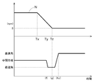
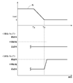
- FIG. 4 shows the rotation speed of the engine E in this control (strictly speaking, the rotation speed of the crankshaft 1: hereinafter, simply The relationship between the valve timing (relative rotation phase) and the number of rotations) is shown in the timing chart.
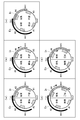
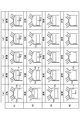
- FIG. 5 shows a diagram of the relationship between the stroke in each cylinder shown by # 1 to # 4 in FIG. 2 and the intake valve Va and the exhaust valve Vb, and this relationship is listed in FIG. It is shown as a figure.
- the states of the same timing along the passage of time are designated by the reference numerals (a) to (e) in the respective figures.
- the reference numerals # 1 to # 4 specify each of the # 1 cylinder, # 2 cylinder, # 3 cylinder, and # 4 cylinder of the engine E shown in FIG. 2, and these cylinders are shown in the stroke diagram. As shown, combustion is performed in the order of # 1 cylinder, # 3 cylinder, # 4 cylinder, and # 2 cylinder.
- the region (720 degrees) in which the crankshaft 1 rotates twice is represented as one circle, and the symbols # 1 to # 4 are assigned to each cylinder, and the intake air is taken according to the stroke. , Compression, expansion, exhaust.
- the region where the intake valve Va opens is marked with an In
- the region where the exhaust valve Vb opens is marked with an Ex.
- the TDC shown in the figure is the top dead center
- the BDC is the bottom dead center.
- this engine stop control when there is a stop request to stop the engine E at the request timing Tx shown in FIG. 4, the rotation speed N of the engine E is reduced by suppressing the fuel supply amount (# 101, (# 102 step), the valve timing of the intake valve Va is set to the maximum advance angle at the set timing Ty when the rotation speed N of the engine E is lower than (reaches less than) the set rotation speed (# 103 step: (# 103 step) in FIG. a)).
- This # 103 step is a specific example of the phase control before stopping.
- the # 1 cylinder is in the compression stroke at the set timing Ty, and the valve timing of the intake valve Va is controlled by the control of the first valve opening / closing timing control device A1 as shown in the timing (a).
- the intake valve Va is closed at the beginning of the compression stroke of the piston 4 of the # 1 cylinder, the amount of gas discharged from the intake valve Va to the intake side is reduced, and the compression ratio in the # 1 cylinder is increased. Increase.
- the # 2 cylinder is in the expansion stroke and the force F1 acts on the piston 4.
- the intake valve Va when shifting from the intake stroke to the compression stroke, the intake valve Va is set immediately before the piston 4 reaches the bottom dead center BDC and at the initial stage when the piston 4 starts to rise in the compression stroke. It is in an open state. Therefore, by setting the valve timing of the intake valve Va to the maximum advance angle at the beginning of the compression stroke and closing the intake valve Va early after reaching the bottom dead center BDC, the # 1 cylinder is closed at the beginning of the compression stroke. The phenomenon that a part of the gas is discharged to the intake side is suppressed, and the compression rate is increased.
- the timing (a) for setting the valve timing of the intake valve Va to the maximum advance angle is minus 180 degrees.
- the cylinder that closes the intake valve Va at an early stage in the compression stroke is not limited to the # 1 cylinder, and may be another cylinder. In this case, the engine E is stopped by the action with the pressure of the cylinder in the intake stroke.
- the intake valve Va is controlled by the first valve opening / closing timing control device A1.
- This # 105 step control is a specific example of post-stop phase control.
- the intake valve Va of the # 3 cylinder already in the compression stroke is opened (FIG. 6).
- the gas of the # 3 cylinder is discharged through this intake valve Va.
- the pressure of the # 3 cylinder drops with respect to the pressure of the # 1 cylinder, and as shown in the timing (e), the pressure of the # 3 cylinder drops, so that the piston 4 of the # 3 cylinder drops at the timing (c).
- the force F3 acting on the force is reduced to the force F4.
- crankshaft 1 slightly rotates in the direction in which the pressure of the # 1 cylinder (force F2) and the pressure of the # 3 cylinder (F4) are balanced (the direction in which the piston 4 of the # 1 cylinder descends), and the timing The equilibrium state shown in (e) is reached, and the rotation of the crankshaft 1 is completely stopped.
- FIG. 7 shows a control mode of the valve timing of the exhaust valve Vb in the engine stop control
- FIG. 8 shows the rotation speed N of the engine E at the time of this control and the valve timing (relative rotation phase) of the exhaust valve Vb. ) Is shown in the timing chart.
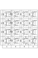
- FIG. 9 shows a diagram of the relationship between the stroke in each cylinder shown by # 1 to # 4 in FIG. 2 and the intake valve Va and the exhaust valve Vb, and this relationship is listed in FIG. It is shown as a figure.
- the states of the same timing along the time axis are designated by the reference numerals (f) to (i) in the respective figures.
- the reference numerals # 1 to # 4 specify each of the # 1 cylinder, # 2 cylinder, # 3 cylinder, and # 4 cylinder of the engine E shown in FIG. 2, and these cylinders are shown in the stroke diagram. As shown, combustion is performed in the order of # 1 cylinder, # 3 cylinder, # 4 cylinder, and # 2 cylinder.
- the region (720 degrees) in which the crankshaft 1 rotates twice is represented as one circle, as in the description of the intake valve Va described above, and # 1 to # correspond to each cylinder.
- a reference numeral 4 is attached to indicate intake, compression, expansion, and exhaust corresponding to the stroke.
- the region where the intake valve Va opens is marked with an In
- the region where the exhaust valve Vb opens is marked with an Ex.
- the TDC shown in the figure is the top dead center
- the BDC is the bottom dead center.
- this engine stop control when a stop signal for stopping the engine E is received at the request timing Tx shown in FIG. 8, the rotation speed N of the engine E is reduced by suppressing the fuel supply amount (# 201, (# 202 step), the valve timing of the exhaust valve Vb is set to the latest angle at the set timing Ty when the engine E rotation speed N is lower than (less than) the set rotation speed (# 203 step: (# 203 step: (# 202 step)). f)).
- This # 203 step is a specific example of phase control before stopping.
- the # 1 cylinder is in the expansion stroke at the set timing Ty, and as shown in the timing (f), the valve timing of the exhaust valve Vb is controlled by the control of the second valve opening / closing timing control device A2.
- the exhaust valve Vb is closed near the end of the expansion stroke of the piston 4 of the # 1 cylinder (immediately before reaching the bottom dead center BDC), and gas is discharged from the exhaust valve Vb to the exhaust side. Gas is trapped in the # 1 cylinder.
- the # 1 cylinder is in the expansion stroke, and the force F6 acts on the piston 4.
- the # 3 cylinder is in the compression stroke, and the force F7 acts on the piston 4 of the # 3 cylinder.
- the piston 4 of the # 1 cylinder reaches the vicinity of the bottom dead center BDC, while the piston 4 of the # 3 cylinder reaches the vicinity of the top dead center TDC, so that the force F7 is applied. It becomes larger than the force F6, and the crankshaft 1 rotates slightly in the reverse direction due to the balance of the force.
- the exhaust valve Vb when shifting from the expansion stroke to the exhaust stroke, the exhaust valve Vb is set immediately before the piston 4 reaches the bottom dead center BDC and at the initial stage when the piston 4 starts to rise in the exhaust stroke. It is in an open state. Therefore, by setting the valve timing of the exhaust valve Vb to the latest angle before the end of the expansion stroke, the exhaust valve Vb is closed at an early stage, and a part of the gas (combustion gas) of the # 1 cylinder in the expansion stroke is released. The phenomenon of being discharged to the exhaust side is suppressed, and the compression rate is increased.
- the cylinder that closes the exhaust valve Vb at an early stage near the end of the expansion stroke is not limited to the # 1 cylinder, and may be another cylinder.
- the engine E is stopped by the action with the pressure of the cylinder in the compression stroke.
- the exhaust valve Vb of the # 1 cylinder is opened (the timing of # 1 in FIG. 10 (the timing of # 1 in FIG. 10). (see h)), the gas of the # 1 cylinder is discharged through the exhaust valve Vb, and the force F8 acting on the piston 4 of the # 1 cylinder is lower than the above-mentioned force F7.
- the crankshaft 1 is stopped in a state where not only the pressure in the cylinder but also the weights of the plurality of pistons 4 and the cam torques of the intake camshaft 7 and the exhaust camshaft 8 are balanced.
- the position is decided. That is, in the engine stop control, the pre-stop phase control that controls the valve timing when there is a stop request (acquisition of a stop signal) to stop the engine E is performed. As a result, the engine E is stopped. After that, by performing phase control after stopping, the engine E is completely stopped in a state where the crankshaft 1 is slightly rotated and balanced.
- the engine stop control when executed for the idling stop control, the engine E is stopped quickly, so that the fuel consumption is suppressed, and when the engine E is started after that, it acts on the crankshaft 1. Since the starter motor 15 can be driven and rotated in a state where the load to be applied is reduced, the crankshaft 1 can be rotated at high speed in a short time, and the starting time can be shortened.
- valve timing of the intake valve Va is maintained at the latest retard angle when the engine E is stopped, so that the valve timing is decompressed when the engine E is started. Cranking is possible, the load at the time of starting is further reduced, the speed of the crank shaft 1 is increased in a short time, and the engine E can be started quickly.
- valve timings of both the first valve opening / closing timing control device A1 and the second valve opening / closing timing control device A2 are controlled.
- this control mode As an example of this control mode, as shown in the timing chart of FIG. 11, when a stop signal for stopping the engine E is received at the requested timing Tx, the rotation speed N of the engine E is reduced by suppressing the fuel supply amount. do. At the time when the rotation speed N of the engine E is reduced in this way, the valve timing of the intake valve Va is set to the latest angle, and the valve timing of the exhaust valve Vb is set to the latest angle.
- the valve timing of the intake valve Va is set to the latest angle
- the valve timing of the exhaust valve Vb is set to the latest angle.
- the engine E is stopped quickly by the same process as the "control of the valve timing of the exhaust valve Vb of the engine stop control" explained in the above, and after that, not only the pressure balance of the plurality of cylinders but also the weight of the plurality of pistons 4 is applied.
- the engine E is stopped in a state in which the balance, the cam surface of the intake cam shaft 7, and the cam torque acting from the cam surface of the exhaust cam shaft 8 are also balanced.
- the engine E is provided with a valve opening / closing timing control device A (in the embodiment, the first valve opening / closing timing control device A1) for controlling the intake valve Va, and during engine stop control. , It is configured to control the valve timing of the intake valve Va.
- the engine E may be provided with an exhaust valve Vb (in the embodiment, the second valve opening / closing timing control device A2) so as to control the valve timing of the exhaust valve Vb at the time of engine stop control.
- the stop target crank angle is set in advance, and the control mode is set so that the engine E is stopped when the crank angle reaches the stop target crank angle.
- the control mode of the stop control device of the internal combustion engine has been described by taking the idling stop as an example.
- the stop control device of the internal combustion engine of the present disclosure is not limited to the idling stop and is an artificial operation. It is also possible to apply it to stop control when stopping the engine E (internal combustion engine).
- This disclosure can be used for a stop control device for an internal combustion engine.
- Engine control device stop control device for internal combustion engine
- a Valve opening / closing timing control device A1 First valve opening / closing timing control device (valve opening / closing timing control device)
- A2 2nd valve open / close timing control device valve open / close timing control device
- E engine internal combustion engine
Landscapes
- Engineering & Computer Science (AREA)
- Mechanical Engineering (AREA)
- General Engineering & Computer Science (AREA)
- Chemical & Material Sciences (AREA)
- Combustion & Propulsion (AREA)
- Output Control And Ontrol Of Special Type Engine (AREA)
- Control Of Vehicle Engines Or Engines For Specific Uses (AREA)
Abstract
Description
〔基本構成〕
図1に示すように、内燃機関としてのエンジンEは、吸気バルブVaと、排気バルブVbとを備え、吸気バルブVaのバルブタイミング(開閉時期)を設定する電動型の第1弁開閉時期制御装置A1と、排気バルブVbのバルブタイミング(開閉時期)を設定する電動型の第2弁開閉時期制御装置A2とを備えている。このエンジンE(内燃機関の一例)は、乗用車等の車両に備えられたものを示している。
クランク角センサ16、第1カム角センサ17、第2カム角センサ18の夫々は、回転に伴いパルス信号を出力するピックアップ型に構成されている。クランク角センサ16は、クランクシャフト1が回転する際に、予め設定されたクランク角を基準(基準角)として連続するパルス信号をクランク角信号として出力する。これにより、クランク角信号をカウントすることで、設定された基準角からのクランク角の検出が可能となる。
つまり、クランク角センサ16と第1カム角センサ17と第2カム角センサ18とを用いることにより、第1弁開閉時期制御装置A1と、第2弁開閉時期制御装置A2との相対回転位相を個別に検出できるように構成されている。
第1弁開閉時期制御装置A1と第2弁開閉時期制御装置A2とは共通する構成を有するものであるが、図2には、弁開閉時期制御装置Aの具体例として第1弁開閉時期制御装置A1の断面を示している。
図2に示すように、位相調節機構Gは、内部ロータ22の内周に回転軸芯Xと同軸芯に形成したリングギヤ26と、内部ロータ22の内周側において回転軸芯Xと平行姿勢の偏心軸芯Yと同軸芯で回転自在に配置されるインナギヤ27と、インナギヤ27の内周側に配置される偏心カム体28と、フロントプレート24と、継手部Jとを備えている。偏心軸芯Yは、回転軸芯Xと平行する姿勢で形成されている。
停止制御部43は、前述したように、アイドリングストップ制御においてエンジンEの停止を迅速に行わせると共に、エンジンEの停止直後にクランクシャフト1に作用する力をバランスさせることにより、クランクシャフト1の僅かな回転を許容してクランク角を安定させる制御を実現する。このようにクランク角を安定させているため、エンジンEの始動時にはクランキングの負荷を低減し、始動性の向上を実現している。
図3のフローチャートには、エンジン停止制御における吸気バルブVaのバルブタイミングの制御形態を示し、図4には、この制御におけるエンジンEの回転数(厳密にはクランクシャフト1の回転数:以下、単に回転数として説明する)と、バルブタイミング(相対回転位相)との関係をタイミングチャートに示している。
図7のフローチャートには、エンジン停止制御における排気バルブVbのバルブタイミングの制御形態を示し、図8には、この制御時におけるエンジンEの回転数Nと、排気バルブVbのバルブタイミング(相対回転位相)との関係をタイミングチャートに示している。
このようにエンジンEを停止する停止要求(停止信号の取得)があった場合には、エンジン停止制御において、弁開閉時期制御装置Aでバルブタイミングを制御するだけで、複数の気筒に封入されたガスの圧力を利用して迅速にエンジンEを停止させることが可能となる。また、エンジンEが停止した後には、弁開閉時期制御装置Aでバルブタイミングを更に制御することにより、気筒内のガスを排出することでクランクシャフト1に対して気筒の圧力に起因して作用する力を低減した状態でのエンジンEの停止を可能にする。このようにエンジンEを停止して状態では、気筒内の圧力だけでなく、複数のピストン4の重量、吸気カムシャフト7及び排気カムシャフト8のカムトルクとのバランスを取る状態でクランクシャフト1の停止位置が決まる。つまり、エンジン停止制御では、エンジンEを停止する停止要求(停止信号の取得)があった場合にバルブタイミングを制御する停止前位相制御を行う。これによりエンジンEが停止する。この後に、停止後位相制御を行うことでクランクシャフト1が僅かに回転しバランスした状態でエンジンEが完全に停止することになる。
本開示は、上記した実施形態以外に以下のように構成しても良い(実施形態と同じ機能を有するものには、実施形態と共通の番号、符号を付している)。
40 エンジン制御装置(内燃機関の停止制御装置)
A 弁開閉時期制御装置
A1 第1弁開閉時期制御装置(弁開閉時期制御装置)
A2 第2弁開閉時期制御装置(弁開閉時期制御装置)
E エンジン(内燃機関)
Va 吸気バルブ
Vb 排気バルブ
Claims (7)
- 4サイクル型の内燃機関が、吸気バルブと排気バルブとの少なくとも一方の開閉時期を設定する電動型の弁開閉時期制御装置を備え、
前記内燃機関を停止させる停止信号を取得した際に、前記内燃機関を停止させる停止制御を行い、当該停止制御により前記内燃機関が停止した後に、前記弁開閉時期制御装置の前記開閉時期を進角方向と遅角方向とのいずれか一方に変位させる停止後位相制御を行う内燃機関の停止制御装置。 - 前記停止後位相制御における前記弁開閉時期制御装置の前記開閉時期の変位方向とは逆方向に前記開閉時期を変位させる停止前位相制御を行う請求項1に記載の内燃機関の停止制御装置。
- 前記弁開閉時期制御装置が、前記吸気バルブの前記開閉時期を設定するものであり、
前記停止前位相制御により前記弁開閉時期制御装置の前記開閉時期を最進角に設定し、前記内燃機関が停止した後に、前記停止後位相制御により前記弁開閉時期制御装置の前記開閉時期を最遅角に設定する請求項2に記載の内燃機関の停止制御装置。 - 前記停止前位相制御は、前記停止制御により前記内燃機関が停止したときのクランクシャフトのクランクアングルを0度とした場合に、前記内燃機関の停止前に前記クランクアングルがマイナス180度に達したときに実行される請求項3に記載の内燃機関の停止制御装置。
- 前記弁開閉時期制御装置が、前記排気バルブの前記開閉時期を設定するものであり、
前記停止制御による前記内燃機関の停止前に前記停止前位相制御により前記弁開閉時期制御装置の前記開閉時期を最遅角に設定し、前記内燃機関が停止した後に、前記停止後位相制御により前記弁開閉時期制御装置の前記開閉時期を最進角に設定する請求項2に記載の内燃機関の停止制御装置。 - 前記停止前位相制御は、前記停止制御により前記内燃機関が停止したときのクランクシャフトのクランクアングルを0度とした場合に、前記内燃機関の停止前に前記クランクアングルがマイナス180度に達したときに実行される請求項5に記載の内燃機関の停止制御装置。
- 前記内燃機関が複数の気筒を備えている請求項1~6のいずれか一項に記載の内燃機関の停止制御装置。
Priority Applications (4)
| Application Number | Priority Date | Filing Date | Title |
|---|---|---|---|
| JP2022533709A JP7397990B2 (ja) | 2020-07-03 | 2021-05-11 | 内燃機関の停止制御装置 |
| US18/002,728 US12012906B2 (en) | 2020-07-03 | 2021-05-11 | Stop control device for internal combustion engine |
| CN202180046660.1A CN115735051B (zh) | 2020-07-03 | 2021-05-11 | 内燃机的停止控制装置 |
| EP21832881.3A EP4177451B1 (en) | 2020-07-03 | 2021-05-11 | Internal combustion engine stopping control device |
Applications Claiming Priority (2)
| Application Number | Priority Date | Filing Date | Title |
|---|---|---|---|
| JP2020115609 | 2020-07-03 | ||
| JP2020-115609 | 2020-07-03 |
Publications (1)
| Publication Number | Publication Date |
|---|---|
| WO2022004135A1 true WO2022004135A1 (ja) | 2022-01-06 |
Family
ID=79315180
Family Applications (1)
| Application Number | Title | Priority Date | Filing Date |
|---|---|---|---|
| PCT/JP2021/017814 Ceased WO2022004135A1 (ja) | 2020-07-03 | 2021-05-11 | 内燃機関の停止制御装置 |
Country Status (5)
| Country | Link |
|---|---|
| US (1) | US12012906B2 (ja) |
| EP (1) | EP4177451B1 (ja) |
| JP (1) | JP7397990B2 (ja) |
| CN (1) | CN115735051B (ja) |
| WO (1) | WO2022004135A1 (ja) |
Families Citing this family (1)
| Publication number | Priority date | Publication date | Assignee | Title |
|---|---|---|---|---|
| JP2025089706A (ja) * | 2023-12-04 | 2025-06-16 | 株式会社アイシン | 弁開閉時期制御装置 |
Citations (5)
| Publication number | Priority date | Publication date | Assignee | Title |
|---|---|---|---|---|
| JP2006125342A (ja) * | 2004-10-29 | 2006-05-18 | Denso Corp | エンジンの停止制御装置 |
| JP2006125276A (ja) * | 2004-10-28 | 2006-05-18 | Toyota Motor Corp | エンジン始動装置 |
| JP2006291792A (ja) * | 2005-04-08 | 2006-10-26 | Toyota Motor Corp | 内燃機関の制御装置 |
| US20100211288A1 (en) * | 2009-02-13 | 2010-08-19 | Ford Global Technologies, Llc | Methods and systems for engine starting |
| JP2011174434A (ja) | 2010-02-25 | 2011-09-08 | Honda Motor Co Ltd | 内燃機関の制御装置 |
Family Cites Families (15)
| Publication number | Priority date | Publication date | Assignee | Title |
|---|---|---|---|---|
| JP2005337110A (ja) * | 2004-05-27 | 2005-12-08 | Denso Corp | 内燃機関 |
| JP2006144567A (ja) | 2004-11-16 | 2006-06-08 | Toyota Motor Corp | 内燃機関のバルブタイミング制御装置 |
| US7243633B2 (en) | 2005-04-22 | 2007-07-17 | Ford Global Technologies, Llc | HEV internal combustion engine pre-positioning |
| JP2008095519A (ja) * | 2006-10-06 | 2008-04-24 | Mazda Motor Corp | エンジンの停止制御装置 |
| JP5476748B2 (ja) * | 2009-03-09 | 2014-04-23 | 日産自動車株式会社 | ハイブリッド車両 |
| US20110100312A1 (en) * | 2009-11-02 | 2011-05-05 | Denso Corporation | Control system for variable valve timing apparatus |
| JP5255003B2 (ja) | 2010-01-25 | 2013-08-07 | 株式会社デンソー | エンジン回転停止制御装置 |
| JP5180249B2 (ja) * | 2010-03-16 | 2013-04-10 | 日立オートモティブシステムズ株式会社 | ハイブリッド車両における可変動弁制御装置 |
| JP2012036864A (ja) * | 2010-08-10 | 2012-02-23 | Hitachi Automotive Systems Ltd | 内燃機関の可変動弁装置と、内燃機関の始動システム及び内燃機関の始動制御装置 |
| JP5666922B2 (ja) * | 2011-01-12 | 2015-02-12 | 日立オートモティブシステムズ株式会社 | バルブタイミング制御装置のコントローラ及び内燃機関のバルブタイミング制御装置 |
| JP5825432B2 (ja) * | 2012-10-30 | 2015-12-02 | トヨタ自動車株式会社 | 内燃機関の制御装置 |
| US9121358B2 (en) * | 2013-02-22 | 2015-09-01 | Borgwarner Inc. | Using camshaft timing device with hydraulic lock in an intermediate position for vehicle restarts |
| JP6142605B2 (ja) * | 2013-03-21 | 2017-06-07 | アイシン精機株式会社 | 内燃機関 |
| JP2018200006A (ja) * | 2017-05-25 | 2018-12-20 | アイシン精機株式会社 | 内燃機関の制御装置 |
| JP7151287B2 (ja) * | 2018-09-04 | 2022-10-12 | トヨタ自動車株式会社 | ミラーサイクルエンジン |
-
2021
- 2021-05-11 CN CN202180046660.1A patent/CN115735051B/zh active Active
- 2021-05-11 US US18/002,728 patent/US12012906B2/en active Active
- 2021-05-11 WO PCT/JP2021/017814 patent/WO2022004135A1/ja not_active Ceased
- 2021-05-11 JP JP2022533709A patent/JP7397990B2/ja active Active
- 2021-05-11 EP EP21832881.3A patent/EP4177451B1/en active Active
Patent Citations (5)
| Publication number | Priority date | Publication date | Assignee | Title |
|---|---|---|---|---|
| JP2006125276A (ja) * | 2004-10-28 | 2006-05-18 | Toyota Motor Corp | エンジン始動装置 |
| JP2006125342A (ja) * | 2004-10-29 | 2006-05-18 | Denso Corp | エンジンの停止制御装置 |
| JP2006291792A (ja) * | 2005-04-08 | 2006-10-26 | Toyota Motor Corp | 内燃機関の制御装置 |
| US20100211288A1 (en) * | 2009-02-13 | 2010-08-19 | Ford Global Technologies, Llc | Methods and systems for engine starting |
| JP2011174434A (ja) | 2010-02-25 | 2011-09-08 | Honda Motor Co Ltd | 内燃機関の制御装置 |
Non-Patent Citations (1)
| Title |
|---|
| See also references of EP4177451A4 |
Also Published As
| Publication number | Publication date |
|---|---|
| US20230243313A1 (en) | 2023-08-03 |
| CN115735051B (zh) | 2025-09-19 |
| CN115735051A (zh) | 2023-03-03 |
| EP4177451B1 (en) | 2026-04-29 |
| US12012906B2 (en) | 2024-06-18 |
| EP4177451A1 (en) | 2023-05-10 |
| JP7397990B2 (ja) | 2023-12-13 |
| JPWO2022004135A1 (ja) | 2022-01-06 |
| EP4177451A4 (en) | 2024-01-10 |
Similar Documents
| Publication | Publication Date | Title |
|---|---|---|
| US5632238A (en) | Control system for an internal combustion engine with associated decompression device | |
| JP2018200006A (ja) | 内燃機関の制御装置 | |
| US20190316497A1 (en) | Control apparatus of valve opening/closing timing control mechanism | |
| US20040000282A1 (en) | Control apparatus for an internal combustion engine and control method thereof | |
| US7191747B2 (en) | Method for starting an internal combustion engine | |
| EP1784566B1 (en) | Shut-down control device of an internal combustion engine | |
| US20200182163A1 (en) | Control device for internal combustion engine | |
| US11725547B2 (en) | Valve opening and closing timing control apparatus device | |
| JP7397990B2 (ja) | 内燃機関の停止制御装置 | |
| US11549407B2 (en) | Valve timing control unit | |
| US11434835B2 (en) | Valve timing controller | |
| JP2018197521A (ja) | 内燃機関の制御装置 | |
| JP4144421B2 (ja) | 内燃機関の制御装置 | |
| JP7559615B2 (ja) | 内燃機関の制御装置 | |
| JP3075126B2 (ja) | 内燃機関のバルブタイミング制御装置 | |
| US12385421B2 (en) | Valve opening and closing timing control device | |
| JP3175243B2 (ja) | 内燃機関のバルブタイミング制御装置 | |
| JP7598439B2 (ja) | 電動バルブタイミング制御装置及び電動バルブタイミング制御方法 | |
| JP4640120B2 (ja) | 内燃機関の制御装置 | |
| JP2017180122A (ja) | 内燃機関の制御装置 | |
| JP2019044594A (ja) | 内燃機関の制御装置 | |
| JP2022178580A (ja) | 触媒劣化判定方法 | |
| WO2022071023A1 (ja) | 弁開閉時期制御装置 | |
| JP2018197520A (ja) | 内燃機関の制御装置 | |
| JP2004332824A (ja) | クランク角位相可変装置 |
Legal Events
| Date | Code | Title | Description |
|---|---|---|---|
| 121 | Ep: the epo has been informed by wipo that ep was designated in this application |
Ref document number: 21832881 Country of ref document: EP Kind code of ref document: A1 |
|
| ENP | Entry into the national phase |
Ref document number: 2022533709 Country of ref document: JP Kind code of ref document: A |
|
| WWE | Wipo information: entry into national phase |
Ref document number: 2021832881 Country of ref document: EP |
|
| NENP | Non-entry into the national phase |
Ref country code: DE |
|
| WWG | Wipo information: grant in national office |
Ref document number: 202180046660.1 Country of ref document: CN |
|
| WWG | Wipo information: grant in national office |
Ref document number: 2021832881 Country of ref document: EP |