WO2022004450A1 - 管理装置、リソグラフィー装置、管理方法および物品製造方法 - Google Patents
管理装置、リソグラフィー装置、管理方法および物品製造方法 Download PDFInfo
- Publication number
- WO2022004450A1 WO2022004450A1 PCT/JP2021/023323 JP2021023323W WO2022004450A1 WO 2022004450 A1 WO2022004450 A1 WO 2022004450A1 JP 2021023323 W JP2021023323 W JP 2021023323W WO 2022004450 A1 WO2022004450 A1 WO 2022004450A1
- Authority
- WO
- WIPO (PCT)
- Prior art keywords
- substrate
- control
- unit
- sequence
- processing
- Prior art date
- Legal status (The legal status is an assumption and is not a legal conclusion. Google has not performed a legal analysis and makes no representation as to the accuracy of the status listed.)
- Ceased
Links
Images




Classifications
-
- G—PHYSICS
- G05—CONTROLLING; REGULATING
- G05B—CONTROL OR REGULATING SYSTEMS IN GENERAL; FUNCTIONAL ELEMENTS OF SUCH SYSTEMS; MONITORING OR TESTING ARRANGEMENTS FOR SUCH SYSTEMS OR ELEMENTS
- G05B13/00—Adaptive control systems, i.e. systems automatically adjusting themselves to have a performance which is optimum according to some preassigned criterion
- G05B13/02—Adaptive control systems, i.e. systems automatically adjusting themselves to have a performance which is optimum according to some preassigned criterion electric
- G05B13/0265—Adaptive control systems, i.e. systems automatically adjusting themselves to have a performance which is optimum according to some preassigned criterion electric the criterion being a learning criterion
- G05B13/027—Adaptive control systems, i.e. systems automatically adjusting themselves to have a performance which is optimum according to some preassigned criterion electric the criterion being a learning criterion using neural networks only
-
- G—PHYSICS
- G03—PHOTOGRAPHY; CINEMATOGRAPHY; ANALOGOUS TECHNIQUES USING WAVES OTHER THAN OPTICAL WAVES; ELECTROGRAPHY; HOLOGRAPHY
- G03F—PHOTOMECHANICAL PRODUCTION OF TEXTURED OR PATTERNED SURFACES, e.g. FOR PRINTING, FOR PROCESSING OF SEMICONDUCTOR DEVICES; MATERIALS THEREFOR; ORIGINALS THEREFOR; APPARATUS SPECIALLY ADAPTED THEREFOR
- G03F7/00—Photomechanical, e.g. photolithographic, production of textured or patterned surfaces, e.g. printing surfaces; Materials therefor, e.g. comprising photoresists; Apparatus specially adapted therefor
- G03F7/0002—Lithographic processes using patterning methods other than those involving the exposure to radiation, e.g. by stamping
-
- G—PHYSICS
- G03—PHOTOGRAPHY; CINEMATOGRAPHY; ANALOGOUS TECHNIQUES USING WAVES OTHER THAN OPTICAL WAVES; ELECTROGRAPHY; HOLOGRAPHY
- G03F—PHOTOMECHANICAL PRODUCTION OF TEXTURED OR PATTERNED SURFACES, e.g. FOR PRINTING, FOR PROCESSING OF SEMICONDUCTOR DEVICES; MATERIALS THEREFOR; ORIGINALS THEREFOR; APPARATUS SPECIALLY ADAPTED THEREFOR
- G03F7/00—Photomechanical, e.g. photolithographic, production of textured or patterned surfaces, e.g. printing surfaces; Materials therefor, e.g. comprising photoresists; Apparatus specially adapted therefor
- G03F7/70—Microphotolithographic exposure; Apparatus therefor
- G03F7/70483—Information management; Active and passive control; Testing; Wafer monitoring, e.g. pattern monitoring
- G03F7/70491—Information management, e.g. software; Active and passive control, e.g. details of controlling exposure processes or exposure tool monitoring processes
- G03F7/705—Modelling or simulating from physical phenomena up to complete wafer processes or whole workflow in wafer productions
-
- G—PHYSICS
- G03—PHOTOGRAPHY; CINEMATOGRAPHY; ANALOGOUS TECHNIQUES USING WAVES OTHER THAN OPTICAL WAVES; ELECTROGRAPHY; HOLOGRAPHY
- G03F—PHOTOMECHANICAL PRODUCTION OF TEXTURED OR PATTERNED SURFACES, e.g. FOR PRINTING, FOR PROCESSING OF SEMICONDUCTOR DEVICES; MATERIALS THEREFOR; ORIGINALS THEREFOR; APPARATUS SPECIALLY ADAPTED THEREFOR
- G03F7/00—Photomechanical, e.g. photolithographic, production of textured or patterned surfaces, e.g. printing surfaces; Materials therefor, e.g. comprising photoresists; Apparatus specially adapted therefor
- G03F7/70—Microphotolithographic exposure; Apparatus therefor
- G03F7/70483—Information management; Active and passive control; Testing; Wafer monitoring, e.g. pattern monitoring
- G03F7/70491—Information management, e.g. software; Active and passive control, e.g. details of controlling exposure processes or exposure tool monitoring processes
- G03F7/70525—Controlling normal operating mode, e.g. matching different apparatus, remote control or prediction of failure
-
- G—PHYSICS
- G03—PHOTOGRAPHY; CINEMATOGRAPHY; ANALOGOUS TECHNIQUES USING WAVES OTHER THAN OPTICAL WAVES; ELECTROGRAPHY; HOLOGRAPHY
- G03F—PHOTOMECHANICAL PRODUCTION OF TEXTURED OR PATTERNED SURFACES, e.g. FOR PRINTING, FOR PROCESSING OF SEMICONDUCTOR DEVICES; MATERIALS THEREFOR; ORIGINALS THEREFOR; APPARATUS SPECIALLY ADAPTED THEREFOR
- G03F7/00—Photomechanical, e.g. photolithographic, production of textured or patterned surfaces, e.g. printing surfaces; Materials therefor, e.g. comprising photoresists; Apparatus specially adapted therefor
- G03F7/70—Microphotolithographic exposure; Apparatus therefor
- G03F7/70691—Handling of masks or workpieces
- G03F7/70716—Stages
- G03F7/70725—Stages control
-
- G—PHYSICS
- G03—PHOTOGRAPHY; CINEMATOGRAPHY; ANALOGOUS TECHNIQUES USING WAVES OTHER THAN OPTICAL WAVES; ELECTROGRAPHY; HOLOGRAPHY
- G03F—PHOTOMECHANICAL PRODUCTION OF TEXTURED OR PATTERNED SURFACES, e.g. FOR PRINTING, FOR PROCESSING OF SEMICONDUCTOR DEVICES; MATERIALS THEREFOR; ORIGINALS THEREFOR; APPARATUS SPECIALLY ADAPTED THEREFOR
- G03F7/00—Photomechanical, e.g. photolithographic, production of textured or patterned surfaces, e.g. printing surfaces; Materials therefor, e.g. comprising photoresists; Apparatus specially adapted therefor
- G03F7/70—Microphotolithographic exposure; Apparatus therefor
- G03F7/70691—Handling of masks or workpieces
- G03F7/70775—Position control, e.g. interferometers or encoders for determining the stage position
-
- G—PHYSICS
- G03—PHOTOGRAPHY; CINEMATOGRAPHY; ANALOGOUS TECHNIQUES USING WAVES OTHER THAN OPTICAL WAVES; ELECTROGRAPHY; HOLOGRAPHY
- G03F—PHOTOMECHANICAL PRODUCTION OF TEXTURED OR PATTERNED SURFACES, e.g. FOR PRINTING, FOR PROCESSING OF SEMICONDUCTOR DEVICES; MATERIALS THEREFOR; ORIGINALS THEREFOR; APPARATUS SPECIALLY ADAPTED THEREFOR
- G03F9/00—Registration or positioning of originals, masks, frames, photographic sheets or textured or patterned surfaces, e.g. automatically
- G03F9/70—Registration or positioning of originals, masks, frames, photographic sheets or textured or patterned surfaces, e.g. automatically for microlithography
- G03F9/7003—Alignment type or strategy, e.g. leveling, global alignment
- G03F9/7042—Alignment for lithographic apparatus using patterning methods other than those involving the exposure to radiation, e.g. by stamping or imprinting
-
- G—PHYSICS
- G05—CONTROLLING; REGULATING
- G05B—CONTROL OR REGULATING SYSTEMS IN GENERAL; FUNCTIONAL ELEMENTS OF SUCH SYSTEMS; MONITORING OR TESTING ARRANGEMENTS FOR SUCH SYSTEMS OR ELEMENTS
- G05B13/00—Adaptive control systems, i.e. systems automatically adjusting themselves to have a performance which is optimum according to some preassigned criterion
- G05B13/02—Adaptive control systems, i.e. systems automatically adjusting themselves to have a performance which is optimum according to some preassigned criterion electric
- G05B13/0265—Adaptive control systems, i.e. systems automatically adjusting themselves to have a performance which is optimum according to some preassigned criterion electric the criterion being a learning criterion
-
- G—PHYSICS
- G05—CONTROLLING; REGULATING
- G05B—CONTROL OR REGULATING SYSTEMS IN GENERAL; FUNCTIONAL ELEMENTS OF SUCH SYSTEMS; MONITORING OR TESTING ARRANGEMENTS FOR SUCH SYSTEMS OR ELEMENTS
- G05B13/00—Adaptive control systems, i.e. systems automatically adjusting themselves to have a performance which is optimum according to some preassigned criterion
- G05B13/02—Adaptive control systems, i.e. systems automatically adjusting themselves to have a performance which is optimum according to some preassigned criterion electric
- G05B13/04—Adaptive control systems, i.e. systems automatically adjusting themselves to have a performance which is optimum according to some preassigned criterion electric involving the use of models or simulators
-
- G—PHYSICS
- G05—CONTROLLING; REGULATING
- G05B—CONTROL OR REGULATING SYSTEMS IN GENERAL; FUNCTIONAL ELEMENTS OF SUCH SYSTEMS; MONITORING OR TESTING ARRANGEMENTS FOR SUCH SYSTEMS OR ELEMENTS
- G05B19/00—Program-control systems
- G05B19/02—Program-control systems electric
- G05B19/418—Total factory control, i.e. centrally controlling a plurality of machines, e.g. direct or distributed numerical control [DNC], flexible manufacturing systems [FMS], integrated manufacturing systems [IMS] or computer integrated manufacturing [CIM]
- G05B19/4184—Total factory control, i.e. centrally controlling a plurality of machines, e.g. direct or distributed numerical control [DNC], flexible manufacturing systems [FMS], integrated manufacturing systems [IMS] or computer integrated manufacturing [CIM] characterised by fault tolerance, reliability of production system
-
- G—PHYSICS
- G06—COMPUTING OR CALCULATING; COUNTING
- G06N—COMPUTING ARRANGEMENTS BASED ON SPECIFIC COMPUTATIONAL MODELS
- G06N3/00—Computing arrangements based on biological models
- G06N3/02—Neural networks
- G06N3/08—Learning methods
- G06N3/092—Reinforcement learning
-
- G—PHYSICS
- G05—CONTROLLING; REGULATING
- G05B—CONTROL OR REGULATING SYSTEMS IN GENERAL; FUNCTIONAL ELEMENTS OF SUCH SYSTEMS; MONITORING OR TESTING ARRANGEMENTS FOR SUCH SYSTEMS OR ELEMENTS
- G05B2219/00—Program-control systems
- G05B2219/30—Nc systems
- G05B2219/45—Nc applications
- G05B2219/45031—Manufacturing semiconductor wafers
-
- G—PHYSICS
- G06—COMPUTING OR CALCULATING; COUNTING
- G06N—COMPUTING ARRANGEMENTS BASED ON SPECIFIC COMPUTATIONAL MODELS
- G06N3/00—Computing arrangements based on biological models
- G06N3/004—Artificial life, i.e. computing arrangements simulating life
- G06N3/006—Artificial life, i.e. computing arrangements simulating life based on simulated virtual individual or collective life forms, e.g. social simulations or particle swarm optimisation [PSO]
Definitions
- the present invention relates to a management device, a lithography device, a management method, and an article manufacturing method.
- Japanese Patent Application Laid-Open No. 2009-205641 describes a position control device including an iterative learning control circuit.
- the position control device includes a detection unit that detects the position of a controlled object, a subtraction unit that generates a deviation obtained by subtracting the output of the detection unit from a target value, and an iterative learning control circuit including a filter to which the deviation is input.
- a calculation means for calculating the parameter variation of the controlled object is provided. The characteristics of the filter are changed according to the parameter variation of the controlled object.
- the parameter value of the neural network can be determined through reinforcement learning.
- the state of the controlled object can change over time, even a neural network that has been optimized at a certain point in time may not be optimal as the state of the controlled object changes thereafter. Therefore, the control accuracy of the control device may decrease as the state of the controlled object changes.
- the present invention provides an advantageous technique for suppressing a decrease in control accuracy due to a change in the state of a controlled object.
- One aspect of the present invention relates to a management device, and the management device is a reward obtained from the control result of the control target by a control unit that controls the control target using a neural network whose parameter value is determined by reinforcement learning. Is provided with a learning unit that redetermines the parameter value by reinforcement learning when the predetermined criterion is not satisfied.
- the block diagram illustrating the configuration of the processing apparatus exemplified in FIG. The figure which illustrates the operation of the management apparatus in a learning sequence.
- the figure which illustrates the operation of the management apparatus in a real sequence The figure which illustrates the structure of the scan exposure apparatus.
- FIG. 1 shows the configuration of the manufacturing system MS of one embodiment.
- the manufacturing system MS may include, for example, a processing device 1, a control device 2 for controlling the processing device 1, and a management device (learning device) 3 for managing the processing device 1 and the control device 2.
- the processing device 1 is a device that executes processing on a processing object, such as a manufacturing device, an inspection device, a monitoring device, and the like.
- the concept of processing may include processing, inspecting, monitoring, observing, etc. of the object to be processed.
- the processing device 1 can control the controlled object by using a neural network that includes a controlled object and whose parameter value is determined by reinforcement learning.
- the control device 2 may be configured to send a drive command to the processing device 1 and receive a driving result or a control result from the processing device 1.
- the management device 3 can perform reinforcement learning to determine a plurality of parameter values of the neural network of the processing device 1. Specifically, the management device 3 repeats the operation of sending a drive command to the processing device 1 and receiving the drive result from the processing device 1 while changing all or part of the plurality of parameter values of the neural network.
- the plurality of parameter values can be determined.
- the management device 3 may be understood as a learning device.
- All or part of the functions of the control device 2 may be incorporated in the management device 3. All or part of the functions of the control device 2 may be incorporated in the processing device 1.
- the processing device 1, the control device 2, and the management device 3 may be physically integrated or configured to be physically separated.
- the processing device 1 may be entirely controlled by the control device 2, or may include components not controlled by the control device 2 in addition to the components controlled by the control device 2.
- FIG. 2 illustrates the configuration of the processing device 1.
- the processing device 1 is a stage mechanism 5 including a stage (holding unit) ST to be controlled, a sensor 6 for detecting the position or state of the stage ST, a driver 7 for driving the stage mechanism 5, and a command value for the driver 7. And may include a control unit 8 that receives the output from the sensor 6.
- the stage ST may hold the positioning object.
- the stage ST can be guided by a guide (not shown).
- the stage mechanism 5 may include an actuator AC that moves the stage ST.
- the driver 7 drives the actuator AC. More specifically, the driver 7 can supply the actuator AC with a current (electrical energy) according to a command value given from the control unit 8, for example.
- the actuator AC can move the stage ST with a force (mechanical energy) corresponding to the current supplied from the driver 7.
- the control unit 8 can control the position or state of the stage ST to be controlled by using a neural network whose parameter value is determined by reinforcement learning.
- FIG. 3 shows a block diagram illustrating the configuration of the processing apparatus 1 exemplified in FIG.
- the control unit 8 may include a subtractor 81, a first compensator 82, a second compensator (neural network) 83, and an adder 84.
- the subtractor 81 can calculate a control deviation which is a difference between a drive command (for example, a target position command) given from the control device 2 and a detection result (for example, the position of the stage ST) output from the sensor 6.
- the first compensator 82 may generate a first command value by performing a compensatory operation on the control deviation provided by the subtractor 81.
- the second compensator 83 is composed of a neural network, and can generate a second command value by performing a compensation operation on the control deviation provided from the subtractor 81.
- the adder 84 can generate a command value by adding the first command value and the second command value.
- the control unit 8, the driver 7, the stage mechanism 5, and the sensor 6 constitute a feedback control system that controls the stage ST as a control target based on the control deviation.
- the first compensator 82 may be, for example, a PID compensator, but may be another compensator.
- the second compensator 83 has an L ⁇ M matrix and M ⁇ N, for example, when the number of inputs is L, the number of intermediate layers is M, and the number of outputs is N (L, M, and N are all positive integers). It can be a neural network defined by the product of a matrix of. The plurality of parameter values of the neural network can be determined or updated by reinforcement learning performed by the management device 3.
- the first compensator 82 is not always necessary, and only the second compensator 82 may generate a command value given to the driver 7.
- the management device 3 can function as a learning unit or a re-learning unit that executes a learning sequence when the reward required from the control result of the stage ST by the control unit 8 of the processing device 1 does not satisfy a predetermined criterion.
- reinforcement learning can determine or redetermine a parameter value set consisting of a plurality of parameter values of the second compensator (neural network) 83.
- FIG. 4 illustrates the operation of the management device 3 in the learning sequence.
- the management device 3 can initialize a plurality of parameter values (parameter value sets) of the second compensator (neural network) 83.
- the management device 3 may send a command to the processing device 1 to drive the stage ST as a control target.
- the management device 3 can send a drive command to the control unit 8 of the processing device 1 via the control device 2.
- the control unit 8 of the processing device 1 can drive the driver 7 to drive the stage ST according to the drive command, and control the position of the stage ST.
- the management device 3 can acquire the drive data indicating the drive state of the stage ST as the control target in the process S102 from the control unit 8 of the processing device 1 via the control device 2.
- the drive data may include, for example, data indicating at least one of the output of the sensor 6 and the output of the subtractor 81.
- the management device 3 can calculate the reward based on the drive data acquired in the process S103. Rewards can be calculated based on a predefined formula. For example, when calculating the reward based on the control deviation, the reward is calculated according to an equation that gives the reciprocal of the control deviation, an equation that gives the reciprocal of the log of the control deviation, or an equation that gives the reciprocal of the quadratic function of the control deviation.
- the larger the reward value, the better the second compensator (neural network) 83, but conversely, the smaller the reward value, the better the second compensator (neural network) 83. ) 83 may mean excellent.
- step S105 the management device 3 modifies at least one of the plurality of parameter values of the second compensator (neural network) 83 to generate a new parameter value set, and the new parameter value is set to the second compensator. (Neural network) Set to 83.
- Steps S106, S107, and S108 can be the same as steps S102, S103, and S104, respectively.
- the management device 3 may send a command to the processing device 1 to drive the stage ST.
- the management device 3 can send a drive command to the control unit 8 of the processing device 1 via the control device 2.
- the control unit 8 of the processing device 1 can drive the driver 7 to drive the stage ST according to the drive command, and control the position of the stage ST.
- the management device 3 can acquire the drive data indicating the drive state of the stage ST in the process S106 from the control unit 8 of the processing device 1 via the control device 2. In the process S108, the management device 3 can calculate the reward based on the drive data acquired in the process S107.
- the management device 3 determines whether or not the reward calculated in the process S108 is higher than the reward calculated in the process S104. Then, when the reward calculated in the process S108 is higher than the reward calculated in the process S104, the management device 3 sets the latest parameter value in the parameter value set after the change is executed in the process S105 in the process S110. Adopt as. On the other hand, when the reward calculated in the process S108 is not higher than the reward calculated in the process S104, the management device 3 rejects the parameter value set after executing the change in the process S105 in the process S111. The process returns to step S105. In this case, in step S105, a new parameter value set is set in the second compensator (neural network) 83.
- the management device 3 determines whether or not the reward calculated in the immediately preceding step S108 meets the predetermined criteria, and if the reward meets the predetermined criteria. Ends the process shown in FIG. This means that the parameter value set generated in the step S105 executed immediately before is determined as the parameter value set after reinforcement learning. A neural network in which a parameter value set after reinforcement learning is set can be called a trained model. On the other hand, when the reward calculated in the step S108 executed immediately before in the step S112 does not satisfy the predetermined standard, the management device 3 repeats the process from the step S105.
- the processing device 1 can operate as a device having a trained model (second compensator 83) obtained in the above learning sequence in a sequence for executing processing on a processing object (this is called an actual sequence).
- the processing apparatus 1 may execute the actual sequence under the control of the management apparatus 3, but in another example, the processing apparatus 1 may execute the actual sequence independently of the management by the management apparatus 3.
- FIG. 5 illustrates the operation of the management device 3 in the actual sequence.
- the management device 3 may cause the processing device 1 to start executing the actual sequence.
- the control unit 8 of the processing device 1 can generate a drive command according to a preset drive profile, drive the driver 7 to drive the stage ST according to the drive command, and control the position of the stage ST.
- the management device 3 can acquire the drive data indicating the drive state of the stage ST in the process S201 from the control unit 8 of the processing device 1 via the control device 2.
- the drive data may include, for example, drive commands and data indicating at least one of the output of the sensor 6 and the output of the subtractor 81 (control deviation).
- the management device 3 can calculate the reward based on the drive data acquired in the process S202.
- Rewards can be calculated based on a predefined formula. This equation may be the same as or different from the equation used in the calculation of rewards in steps S104, 108 of the learning sequence shown in FIG.
- the reward in the learning sequence, can be calculated based on the time until the control deviation converges below the threshold value, and in the real sequence, the reward can be calculated based on the moving average of the control deviation.
- the management device 3 determines whether or not the reward calculated in the process S203 satisfies the predetermined criterion. Then, the management device 3 returns to step S201 when the reward meets the predetermined criterion, proceeds to step S205 when the reward does not meet the predetermined criterion, and is exemplified in FIG. 4 in step S205.
- Perform a learning sequence ie, relearning.
- the timing for executing the learning sequence (re-learning) in step S205 the following timing can be exemplified. (1) In the first example, the learning sequence can be performed immediately after it is determined in step S204 that the reward does not meet the predetermined criteria.
- the learning sequence may be executed before the start of the next real sequence (that is, the period during which the real sequence is not executed), waiting for the end of the real sequence currently being executed.
- the learning sequence may be executed before the start of the next real sequence (that is, the period during which the real sequence is not executed), waiting for the end of the real sequence currently being executed.
- the training sequence in step S205 can be executed starting from the current trained model.
- the learning sequence in step S205 may be executed after returning the neural network to an initial state or an arbitrary state of the learning process.
- the scanning exposure apparatus 500 is a step-and-scan exposure apparatus that scan-exposes the substrate 14 with the slit light shaped by the slit member.
- the scanning exposure device 500 includes an illumination optical system 23, an original plate stage mechanism 12, a projection optical system 13, a substrate stage mechanism 15, a first position measurement unit 17, a second position measurement unit 18, a substrate mark measurement unit 21, and a substrate transfer unit 22.
- the control unit 25 may be included.
- the control unit 25 includes an illumination optical system 23, an original plate stage mechanism 12, a projection optical system 13, a substrate stage mechanism 15, a first position measurement unit 17, a second position measurement unit 18, a substrate mark measurement unit 21, and a substrate transfer unit 22. Control.
- the control unit 25 controls the process of transferring the pattern of the original plate 11 to the substrate 14.
- the control unit 25 is, for example, a PLD (abbreviation for Programmable Logic Device) such as FPGA (abbreviation for Field Programmable Gate Array), or an ASIC (Application Specific Integrated Circuit) general-purpose program, abbreviated as ASIC. It may consist of a computer or a combination of all or part of these.
- the control unit 25 may correspond to the control unit 8 in the processing device 1 shown in FIGS. 2 and 3.
- the original plate stage mechanism 12 may include an original plate stage RST that holds the original plate 11 and a first actuator RAC that drives the original plate stage RST.
- the substrate stage mechanism 15 may include a substrate stage WST that holds the substrate 14 and a second actuator WAC that drives the substrate stage WST.
- the illumination optical system 23 illuminates the original plate 11.
- the illumination optical system 23 uses a light-shielding member such as a mask king blade to shape the light emitted from a light source (not shown) into slit light having a long band-shaped or arc-shaped shape in the X direction, and the slit light is used. Illuminate a part of the original plate 11.
- the original plate 11 and the substrate 14 are held by the original plate stage RST and the substrate stage WST, respectively, and are arranged at substantially conjugate positions (object plane and image plane of the projection optical system 13) via the projection optical system 13, respectively. Will be done.
- the projection optical system 13 has a predetermined projection magnification (for example, 1x, 1/2x, or 1/4x), and the pattern of the original plate 11 is projected onto the substrate 14 by slit light.
- the region on the substrate 14 on which the pattern of the original plate 11 is projected (the region where the slit light is irradiated) can be called an irradiation region.
- the original stage RST and the substrate stage WST are configured to be movable in a direction (Y direction) orthogonal to the optical axis direction (Z direction) of the projection optical system 13.
- the original stage RST and the substrate stage WST are relatively scanned at a speed ratio corresponding to the projection magnification of the projection optical system 13 while synchronizing with each other.
- the substrate 14 is scanned in the Y direction with respect to the irradiation region, and the pattern formed on the original plate 11 is transferred to the shot region of the substrate 14. Then, by sequentially performing such scanning exposure for each of the plurality of shot regions of the substrate 14 while moving the substrate stage WST, the exposure process on one substrate 14 is completed.
- the first position measuring unit 17 includes, for example, a laser interferometer, and measures the position of the original stage RST.
- the laser interferometer for example, irradiates a laser beam toward a reflector (not shown) provided on the original stage RST, and causes interference between the laser beam reflected by the reflector and the laser beam reflected by the reference plane.
- the displacement (displacement from the reference position) of the original stage RST is detected.
- the first position measuring unit 17 can acquire the current position of the original stage RST based on the displacement.
- the first position measuring unit 17 may measure the position of the original stage RST by a position measuring instrument, for example, an encoder, in addition to the laser interferometer.
- the substrate mark measuring unit 21 includes, for example, an optical system and an image pickup element, and can detect the position of a mark provided on the substrate 14.
- the second position measuring unit 18 includes, for example, a laser interferometer, and measures the position of the substrate stage WST.
- the laser interferometer for example, irradiates a laser beam toward a reflector (not shown) provided on the substrate stage WST, and causes interference between the laser beam reflected by the reflector and the laser beam reflected by the reference plane.
- the displacement (displacement from the reference position) of the substrate stage WST is detected.
- the second position measuring unit 18 can acquire the current position of the substrate stage WST based on the displacement.
- the second position measuring unit 18 may measure the position of the substrate stage WST by a position measuring instrument, for example, an encoder, in addition to the laser interferometer.
- the scanning exposure apparatus 500 is required to accurately transfer the pattern of the original plate 11 to the target position of the substrate 14. For that purpose, it is important to accurately control the relative position of the original plate 11 on the original plate stage RST with respect to the substrate 14 on the substrate stage WST during scanning exposure. Therefore, as a reward, a value for evaluating the relative position error (synchronization error) between the original stage RST and the substrate stage WST can be adopted. Further, in order to improve the detection accuracy of the mark on the substrate 14, it is important to accurately position the substrate stage WST under the substrate mark measuring unit 21, and as a reward, while the mark is being imaged. A value for evaluating the control deviation of the substrate stage WST of the above can be adopted.
- the substrate stage mechanism 15, the original plate stage mechanism 12, and the substrate transfer unit 22 are examples of operating units that perform operations for transferring the pattern of the original plate 11 to the substrate 14, respectively.
- FIG. 7 illustrates an actual sequence of the scanning exposure apparatus 500.
- the management device 3 instructs the control unit 25 of the scanning exposure device 500 to start executing the actual sequence, that is, the processing sequence for processing the substrate.
- the scanning exposure apparatus 500 initiates the processing sequence.
- the processing sequence may include, for example, steps S302, S303, S304, S305 as the plurality of subsequences.
- step S302 the control unit 25 controls the substrate transfer unit 22 so as to load (transfer) the substrate 14 to the substrate stage WST. Specifically, in step S302, the control unit 25 controls the substrate stage mechanism 15 so that the mark on the substrate 14 is in the field of view of the substrate mark measurement unit 21, so that the position of the mark on the substrate 14 is detected. The board mark measuring unit 21 can be controlled. Such an operation can be performed for each of the plurality of marks on the substrate 14. In step S304, the control unit 25 controls the substrate stage mechanism 15, the original plate stage mechanism 12, the illumination optical system 23, and the like so that the pattern of the original plate 11 is transferred to each of the plurality of shot regions of the substrate 14.
- step S305 the control unit 25 controls the substrate transfer unit 22 so as to unload (transfer) the substrate 14 on the substrate stage WST.
- the drive data required for calculating the reward related to the control in the processes S302, S303, S304, and S305 is transmitted from the control unit 25 (control unit 8) to the management device 3 via the control device 2. Can be provided to.
- Such drive data may be collectively provided from the control unit 25 (control unit 8) to the management device 3 via the control device 2 after the end of the step S305.
- the management device 3 calculates the reward for control in each of the plurality of subsequences, that is, the processes S302, S303, S304, and S305, based on the drive data. For example, with respect to the control in steps S302 and S305, a value for evaluating the time required for the control deviation of the substrate stage or the holding portion for holding the substrate to converge to the specified value or less can be calculated as a reward. Regarding the control in the step S303, as a reward, a value for evaluating the control deviation of the substrate stage (holding unit) during the measurement of the alignment error between the substrate and the original plate can be calculated. For the control in step S304, as a reward, a value for evaluating the synchronization error between the substrate and the original plate during exposure of the substrate can be calculated.
- the management device 3 determines whether or not the reward calculated in the process S306 satisfies the predetermined standard. Then, the management device 3 ends the actual sequence shown in FIG. 7 when the reward meets the predetermined criterion, and proceeds to step S308 when the reward does not meet the predetermined criterion, and in step S308. , The learning sequence (re-learning) illustrated in FIG. 4 is executed.
- the management device 3 can determine whether or not the reward satisfies the corresponding criteria for each of the plurality of subsequences, that is, steps S302, S303, S304, and S305.
- the management device 3 may operate to execute the learning sequence for the subsequence in which the reward does not meet the standard.
- the management device 3 executes a learning sequence for all the subsequences, that is, at least one of the steps S302, S303, S304, S305, when the reward does not meet the corresponding criteria. May be good.
- the calculated reward is a value that evaluates the time required for the control deviation of the board stage or holding part that holds the board to converge to the specified value or less
- the corresponding standard also converges the control deviation to the specified value or less. It is given as the time it takes to do.
- the calculated reward is a value that evaluates the control deviation of the substrate stage during the measurement of the alignment error between the substrate and the original plate
- the corresponding criterion may also be given as the control deviation of the substrate stage during the measurement of the alignment error. ..
- the calculated reward is a value that evaluates the synchronization error between the substrate and the original plate during the exposure of the substrate
- a corresponding criterion may also be given by the synchronization error between the substrate and the original plate during the exposure of the substrate.
- Examples of the control target in which the neural network is configured include the substrate stage mechanism 15, the original plate stage mechanism 12, the substrate transport unit 22, and the like, but the neural network may also be incorporated in other components.
- a plurality of components such as the board stage mechanism 15, the original plate stage mechanism 12, and the board transfer unit 22 may be controlled by one neural network, or the plurality of components may be controlled by different neural networks. You may.
- the trained model the same trained model may be used for each of the transport sequence, the measurement sequence, and the exposure sequence, or different trained models may be used. In the calculation of the reward, the same formula may be used for the transport sequence, the measurement sequence, and the exposure sequence, or different formulas may be used.
- the horizontal axis is time (time), and the vertical axis is the control deviation (error) of the controlled object.
- the control deviation of the controlled object is the curve 50 in the period until the control deviation of the controlled object falls below the threshold value
- the period 52 until the curve 50 falls below the threshold value 54 is adopted as a reward. sell.
- the measurement sequence assuming that the measurement period for measuring the position of the mark on the substrate is the period 53 and the control deviation of the substrate stage WST in the period 53 is the curve 51, the average value of the curve 51 can be adopted as a reward.
- the exposure sequence assuming that the exposure period is the period 53 and the synchronization error between the substrate stage WST and the original stage RST in the period 53 is the curve 51, the moving average and the moving variance of the curve 51 can be adopted as rewards.
- step S308 The timing for executing the learning in step S308 is, for example, immediately after the execution of the sequence is completed, between the processing for one substrate and the processing for the next substrate, or after the processing of the substrate using the same original plate is completed. Can be considered.
- the learning of step S308 may be performed, for example, in parallel with the maintenance of the components of the light source.
- the manufacturing system MS may be applied to other types of exposure apparatus (for example, a stepper), or may be applied to other types such as an imprinting apparatus. May be applied to the type of lithography equipment.
- the lithography apparatus is an apparatus for forming a pattern on a substrate, and the concept may include an exposure apparatus, an imprint apparatus, an electron beam drawing apparatus, and the like.
- the article manufacturing method includes a transfer step of transferring a pattern of an original plate to a substrate by a lithography apparatus and a processing step of processing the substrate through the transfer step, and a method of obtaining an article from the substrate through the processing step.
- a transfer step of transferring a pattern of an original plate to a substrate by a lithography apparatus and a processing step of processing the substrate through the transfer step and a method of obtaining an article from the substrate through the processing step.
- the article manufacturing method consists of a step of exposing a substrate (a substrate, a glass substrate, etc.) coated with a photosensitive agent, a step of developing the substrate (photosensitizer), and a step of developing the substrate. It may include a step of processing the substrate in another well known step. Other well-known steps include etching, resist stripping, dicing, bonding, packaging and the like. According to this article manufacturing method, it is possible to manufacture an article of higher quality than before.
- the article manufacturing method includes a step of forming a pattern made of a cured product of the imprint material by molding the imprint material on the substrate using a mold, and the pattern. It may include a step of processing the substrate using it.
Landscapes
- Engineering & Computer Science (AREA)
- Physics & Mathematics (AREA)
- General Physics & Mathematics (AREA)
- Artificial Intelligence (AREA)
- Evolutionary Computation (AREA)
- Software Systems (AREA)
- Health & Medical Sciences (AREA)
- Automation & Control Theory (AREA)
- Computer Vision & Pattern Recognition (AREA)
- Medical Informatics (AREA)
- Theoretical Computer Science (AREA)
- General Engineering & Computer Science (AREA)
- Computational Linguistics (AREA)
- Mathematical Physics (AREA)
- Biomedical Technology (AREA)
- Biophysics (AREA)
- Life Sciences & Earth Sciences (AREA)
- Data Mining & Analysis (AREA)
- General Health & Medical Sciences (AREA)
- Molecular Biology (AREA)
- Computing Systems (AREA)
- Quality & Reliability (AREA)
- Manufacturing & Machinery (AREA)
- Exposure And Positioning Against Photoresist Photosensitive Materials (AREA)
- Container, Conveyance, Adherence, Positioning, Of Wafer (AREA)
- Feedback Control In General (AREA)
Abstract
管理装置は、強化学習によってパラメータ値が決定されるニューラルネットワークを使って制御対象を制御する制御部による前記制御対象の制御結果から求められる報酬が所定基準を満たさない場合に、強化学習によって前記パラメータ値を再決定する学習部を備える。
Description
本発明は、管理装置、リソグラフィー装置、管理方法および物品製造方法に関する。
特開2009-205641号公報には、反復学習制御回路を備える位置制御装置が記載されている。該位置制御装置は、制御対象の位置を検出する検出部と、該検出部の出力を目標値から減算した偏差を生成する減算部と、該偏差が入力されるフィルタを含む反復学習制御回路と、該制御対象のパラメータ変動を算出する算出手段とを備える。該フィルタの特性は、該制御対象のパラメータ変動に応じて変更される。
ニューラルネットワークを用いた制御装置は、強化学習を経てニューラルネットワークのパラメータ値が決定されうる。しかし、制御対象の状態は、経時変化によって変化しうるので、ある時点で最適化されていたニューラルネットワークであっても、その後の制御対象の状態の変化に伴って最適ではなくなりうる。そのため、制御対象の状態の変化に伴って、制御装置の制御精度が低下しうる。
本発明は、制御対象の状態の変化による制御精度の低下を抑えるために有利な技術を提供する。
本発明の1つの側面は、管理装置に係り、前記管理装置は、強化学習によってパラメータ値が決定されるニューラルネットワークを使って制御対象を制御する制御部による前記制御対象の制御結果から求められる報酬が所定基準を満たさない場合に、強化学習によって前記パラメータ値を再決定する学習部を備える。
以下、添付図面を参照して実施形態を詳しく説明する。尚、以下の実施形態は特許請求の範囲に係る発明を限定するものではない。実施形態には複数の特徴が記載されているが、これらの複数の特徴の全てが発明に必須のものとは限らず、また、複数の特徴は任意に組み合わせられてもよい。さらに、添付図面においては、同一若しくは同様の構成に同一の参照番号を付し、重複した説明は省略する。
図1には、一実施形態の製造システムMSの構成が示されている。製造システムMSは、例えば、処理装置1と、処理装置1を制御する制御装置2と、処理装置1および制御装置2を管理する管理装置(学習装置)3とを備えうる。処理装置1は、例えば、製造装置、検査装置、監視装置等のように、処理対象物に対する処理を実行する装置である。処理の概念には、処理対象物を加工すること、検査すること、監視すること、観察することなどが含まれうる。
処理装置1は、制御対象を含み、強化学習によってパラメータ値が決定されるニューラルネットワークを使って該制御対象を制御しうる。制御装置2は、処理装置1に駆動指令を送り、処理装置1から駆動結果あるいは制御結果を受け取るように構成されうる。管理装置3は、処理装置1のニューラルネットワークの複数のパラメータ値を決定する強化学習を行いうる。具体的には、管理装置3は、処理装置1に駆動指令を送り、処理装置1から駆動結果を受け取る動作を該ニューラルネットワークの該複数のパラメータ値の全部または一部を変更しながら繰り返すことによって該複数のパラメータ値を決定しうる。管理装置3は、学習装置として理解されてもよい。
制御装置2の全部または一部の機能は、管理装置3に組み込まれてもよい。制御装置2の全部または一部の機能は、処理装置1に組み込まれてもよい。処理装置1、制御装置2および管理装置3は、物理的に一体化されて構成されてもよいし、物理的に別体をなすように構成されてもよい。処理装置1は、その全体が制御装置2によって制御されてもよいし、制御装置2によって制御される構成要素の他に、制御装置2によって制御されない構成要素を含んでもよい。
図2には、処理装置1の構成が例示されている。処理装置1は、制御対象であるステージ(保持部)STを含むステージ機構5と、ステージSTの位置あるいは状態を検出するセンサ6と、ステージ機構5を駆動するドライバ7と、ドライバ7に指令値を与え、センサ6からの出力を受け取る制御部8とを含みうる。ステージSTは、位置決め対象物を保持しうる。ステージSTは、不図示のガイドによってガイドされうる。ステージ機構5は、ステージSTを移動させるアクチュエータACを含みうる。ドライバ7は、アクチュエータACを駆動する。より具体的には、ドライバ7は、例えば、制御部8から与えられる指令値に応じた電流(電気的エネルギー)をアクチュエータACに供給しうる。アクチュエータACは、ドライバ7から供給される電流に応じた力(機械的エネルギー)でステージSTを移動させうる。制御部8は、強化学習によってパラメータ値が決定されるニューラルネットワークを使って制御対象であるステージSTの位置あるいは状態を制御しうる。
図3には、図2に例示された処理装置1の構成を例示するブロック線図が示されている。制御部8は、減算器81と、第1補償器82と、第2補償器(ニューラルネットワーク)83と、加算器84とを含みうる。減算器81は、制御装置2から与えられる駆動指令(例えば、目標位置指令)とセンサ6から出力される検出結果(例えば、ステージSTの位置)との差分である制御偏差を演算しうる。第1補償器82は、減算器81から提供される制御偏差に対して補償演算を行って第1指令値を発生しうる。第2補償器83は、ニューラルネットワークで構成され、減算器81から提供される制御偏差に対して補償演算を行って第2指令値を発生しうる。加算器84は、第1指令値と第2指令値とを加算し指令値を発生しうる。制御部8、ドライバ7、ステージ機構5およびセンサ6は、制御偏差に基づいて制御対象としてのステージSTを制御するフィードバック制御系を構成している。
第1補償器82は、例えば、PID補償器でありうるが、他の補償器であってもよい。第2補償器83は、例えば、入力数をL、中間層数をM、出力数をN(L、M、Nはいずれも正の整数)とした時に、L×Mの行列とM×Nの行列との積で定義されるニューラルネットワークでありうる。該ニューラルネットワークの複数のパラメータ値は、管理装置3によって実行される強化学習によって決定あるいは更新されうる。第1補償器82は、必ずしも必要ではなく、第2補償器82のみがドライバ7に与える指令値を発生してもよい。
管理装置3は、処理装置1の制御部8によるステージSTの制御結果から求められる報酬が所定基準を満たさない場合に学習シーケンスを実行する学習部あるいは再学習部として機能しうる。学習シーケンスでは、強化学習によって第2補償器(ニューラルネットワーク)83の複数のパラメータ値からなるパラメータ値セットを決定あるいは再決定されうる。
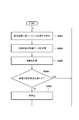
図4には、学習シーケンスにおける管理装置3の動作が例示されている。工程S101では、管理装置3は、第2補償器(ニューラルネットワーク)83の複数のパラメータ値(パラメータ値セット)を初期化しうる。工程S102では、管理装置3は、制御対象としてのステージSTを駆動するように処理装置1に指令を送りうる。具体的には、工程S102では、管理装置3は、駆動指令を制御装置2を介して処理装置1の制御部8に送りうる。これに応答して、処理装置1の制御部8は、駆動指令に従ってドライバ7にステージSTを駆動させ、ステージSTの位置を制御しうる。
工程S103では、管理装置3は、工程S102における制御対象としてのステージSTの駆動の状態を示す駆動データを制御装置2を介して処理装置1の制御部8から取得しうる。駆動データは、例えば、センサ6の出力および減算器81の出力の少なくとも1つを示すデータを含みうる。工程S104では、管理装置3は、工程S103で取得した駆動データに基づいて報酬を計算しうる。報酬は、予め定義された式に基づいて計算されうる。例えば、制御偏差に基づいて報酬を計算する場合、報酬は、制御偏差の逆数を与える式、制御偏差の対数の逆数を与える式、または、制御偏差の二次関数の逆数を与える式等に従って計算されうるが、他の式に従って計算されてもよい。一例においては、報酬の値が大きいほど、第2補償器(ニューラルネットワーク)83が優秀であることを意味するが、これとは逆に、報酬の値が小さいほど、第2補償器(ニューラルネットワーク)83が優秀であることを意味する場合もある。
工程S105では、管理装置3は、第2補償器(ニューラルネットワーク)83の複数のパラメータ値の少なくとも1つを変更して、新たなパラメータ値セットを生成し、新たなパラメータ値を第2補償器(ニューラルネットワーク)83に設定する。工程S106、S107、S108は、工程S102、S103、S104とそれぞれ同じでありうる。工程S106では、管理装置3は、ステージSTを駆動するように処理装置1に指令を送りうる。具体的には、工程S106では、管理装置3は、駆動指令を制御装置2を介して処理装置1の制御部8に送りうる。これに応答して、処理装置1の制御部8は、駆動指令に従ってドライバ7にステージSTを駆動させ、ステージSTの位置を制御しうる。工程S107では、管理装置3は、工程S106におけるステージSTの駆動の状態を示す駆動データを制御装置2を介して処理装置1の制御部8から取得しうる。工程S108では、管理装置3は、工程S107で取得した駆動データに基づいて報酬を計算しうる。
工程S109では、管理装置3は、工程S108で計算した報酬が工程S104で計算した報酬より向上しているかどうかを判定する。そして、管理装置3は、工程S108で計算した報酬が工程S104で計算した報酬より向上している場合には、工程S110において、工程S105において変更を実行した後のパラメータ値セットを最新のパラメータ値として採用する。一方、管理装置3は、工程S108で計算した報酬が工程S104で計算した報酬より向上していない場合には、工程S111において、工程S105において変更を実行した後のパラメータ値セットを不採用とし、工程S105に戻る。この場合、工程S105において、第2補償器(ニューラルネットワーク)83に新たなパラメータ値セットを設定される。
工程S110が実行された場合には、工程S112において、管理装置3は、直前に実行された工程S108で計算した報酬が所定基準を満たすかどうかを判定し、該報酬が所定基準を満たす場合には、図4に示される処理を終了する。これは、直前に実行された工程S105で生成されたパラメータ値セットが強化学習後のパラメータ値セットとして決定されることを意味する。強化学習後のパラメータ値セットが設定されたニューラルネットワークは、学習済モデルと呼ばれうる。一方、工程S112において直前に実行された工程S108で計算した報酬が所定基準を満たさない場合、管理装置3は、工程S105からの処理を繰り返す。
処理装置1は、処理対象物に対する処理を実行するシーケンス(これを実シーケンスと呼ぶ)において、上記の学習シーケンスで得られた学習済モデル(第2補償器83)を有する装置として動作しうる。一例において、処理装置1は、管理装置3による管理下において実シーケンスを実行しうるが、他の例において、処理装置1は、管理装置3による管理とは独立して実シーケンスを実行しうる。
図5には、実シーケンスにおける管理装置3の動作が例示されている。工程S201では、管理装置3は、処理装置1に実シーケンスの実行を開始させうる。実シーケンスにおいて、処理装置1の制御部8は、予め設定された駆動プロファイルに従って駆動指令を発生し、該駆動指令に従ってドライバ7にステージSTを駆動させ、ステージSTの位置を制御しうる。工程S202では、管理装置3は、工程S201におけるステージSTの駆動の状態を示す駆動データを制御装置2を介して処理装置1の制御部8から取得しうる。駆動データは、例えば、駆動指令、および、センサ6の出力および減算器81の出力(制御偏差)の少なくとも1つを示すデータを含みうる。工程S203では、管理装置3は、工程S202で取得した駆動データに基づいて報酬を計算しうる。報酬は、予め定義された式に基づいて計算されうる。この式は、図4に示される学習シーケンスの工程S104、108における報酬の計算において使用される式と同じであってもよいし、異なってもよい。例えば、学習シーケンスでは、制御偏差が閾値以下に収束するまでの時間に基づいて報酬を計算し、実シーケンスでは、制御偏差の移動平均に基づいて報酬を計算することができる。学習シーケンスでは、変化に敏感な指標を使うことで学習の精度を高め、実シーケンスでは、計算負荷が小さい式に従って報酬を計算することが有用である。
工程S204では、管理装置3は、工程S203で計算した報酬が所定基準を満たすかどうかを判断する。そして、管理装置3は、該報酬が該所定基準を満たす場合は、工程S201に戻り、該報酬が該所定基準を満たさない場合には、工程S205に進み、工程S205において、図4に例示される学習シーケンス(即ち、再学習)を実行する。工程S205において、学習シーケンス(再学習)を実行するタイミングとしては、次のようなタイミングを例示的に挙げることができる。
(1)第1の例では、学習シーケンスは、工程S204において報酬が所定基準を満たさないと判断された直後に実施されうる。
(2)第2の例では、現在実行中の実シーケンスの終了を待ち、次の実シーケンスの開始前(即ち、実シーケンスを実行してない期間)に、学習シーケンスが実行されうる。
(3)第3の例では、報酬が所定基準を満たさなかったことを記憶しておき、次回のメンテナンス工程において学習シーケンスが実行されうる。
(1)第1の例では、学習シーケンスは、工程S204において報酬が所定基準を満たさないと判断された直後に実施されうる。
(2)第2の例では、現在実行中の実シーケンスの終了を待ち、次の実シーケンスの開始前(即ち、実シーケンスを実行してない期間)に、学習シーケンスが実行されうる。
(3)第3の例では、報酬が所定基準を満たさなかったことを記憶しておき、次回のメンテナンス工程において学習シーケンスが実行されうる。
工程S205における学習シーケンスは、現在の学習済モデルを出発点として実行されうる。あるいは、工程S205における学習シーケンスは、ニューラルネットワークを初期状態または学習過程の任意の状態に戻してから実行されうる。
以下、図6を参照しながら上記の製造システムMSを走査露光装置500に適用した例を説明する。走査露光装置500は、スリット部材によって整形されたスリット光により基板14を走査露光するステップ・アンド・スキャン方式の露光装置である。走査露光装置500は、照明光学系23、原版ステージ機構12、投影光学系13、基板ステージ機構15、第1位置計測部17、第2位置計測部18、基板マーク計測部21、基板搬送部22および制御部25を含みうる。
制御部25は、照明光学系23、原版ステージ機構12、投影光学系13、基板ステージ機構15、第1位置計測部17、第2位置計測部18、基板マーク計測部21、基板搬送部22を制御する。制御部25は、原版11のパターンを基板14に転写する処理を制御する。制御部25は、例えば、FPGA(Field Programmable Gate Arrayの略。)などのPLD(Programmable Logic Deviceの略。)、又は、ASIC(Application Specific Integrated Circuitの略。)、又は、プログラムが組み込まれた汎用コンピュータ、又は、これらの全部または一部の組み合わせによって構成されうる。制御部25は、図2、図3に記載された処理装置1における制御部8に相当しうる。
原版ステージ機構12は、原版11を保持する原版ステージRSTと、原版ステージRSTを駆動する第1アクチュエータRACとを含みうる。基板ステージ機構15は、基板14を保持する基板ステージWSTと、基板ステージWSTを駆動する第2アクチュエータWACとを含みうる。照明光学系23は、原版11を照明する。照明光学系23は、マスクキングブレードなどの遮光部材により、光源(不図示)から射出された光を、例えばX方向に長い帯状または円弧状の形状を有するスリット光に整形し、そのスリット光で原版11の一部を照明する。原版11および基板14は、原版ステージRSTおよび基板ステージWSTによってそれぞれ保持されており、投影光学系13を介して光学的にほぼ共役な位置(投影光学系13の物体面および像面)にそれぞれ配置される。
投影光学系13は、所定の投影倍率(例えば、1倍、1/2倍又は1/4倍)を有し、原版11のパターンをスリット光により基板14上に投影する。原版11のパターンが投影された基板14上の領域(スリット光が照射される領域)は、照射領域と呼ばれうる。原版ステージRSTおよび基板ステージWSTは、投影光学系13の光軸方向(Z方向)に直交する方向(Y方向)に移動可能に構成されている。原版ステージRSTおよび基板ステージWSTは、互いに同期しながら、投影光学系13の投影倍率に応じた速度比で相対的に走査される。これにより、照射領域に対して基板14がY方向に走査され、原版11に形成されたパターンが基板14のショット領域に転写される。そして、このような走査露光を、基板ステージWSTを移動させながら、基板14の複数のショット領域の各々について順次に行うことにより、1枚の基板14における露光処理が完了する。
第1位置計測部17は、例えばレーザ干渉計を含み、原版ステージRSTの位置を計測する。レーザ干渉計は、例えば、レーザ光を原版ステージRSTに設けられた反射板(不図示)に向けて照射し、反射板で反射されたレーザ光と基準面で反射されたレーザ光との干渉によって原版ステージRSTの変位(基準位置からの変位)を検出する。第1位置計測部17は、当該変位に基づいて原版ステージRSTの現在位置を取得することができる。ここで、第1位置計測部17は、レーザ干渉計以外に位置計測器、例えば、エンコーダによって原版ステージRSTの位置を計測してもよい。基板マーク計測部21は、例えば、光学系および撮像素子を含み、基板14に設けられたマークの位置を検出しうる。
第2位置計測部18は、例えばレーザ干渉計を含み、基板ステージWSTの位置を計測する。レーザ干渉計は、例えば、レーザ光を基板ステージWSTに設けられた反射板(不図示)に向けて照射し、反射板で反射されたレーザ光と基準面で反射されたレーザ光との干渉によって基板ステージWSTの変位(基準位置からの変位)を検出する。第2位置計測部18は、当該変位に基づいて基板ステージWSTの現在位置を取得することができる。ここで、第2位置計測部18は、レーザ干渉計以外に位置計測器、例えば、エンコーダによって基板ステージWSTの位置を計測してもよい。
走査露光装置500では、原版11のパターンを基板14の目標位置に正確に転写することが求められる。そのためには、走査露光中における基板ステージWST上の基板14に対する原版ステージRST上の原版11の相対位置を正確に制御することが重要である。よって、報酬としては、原版ステージRSTと基板ステージWSTとの相対位置誤差(同期誤差)を評価する値を採用しうる。また、基板14のマークの検出精度を向上させるためには、基板ステージWSTを基板マーク計測部21の下に正確に位置決めすることが重要であるため、報酬としては、マークを撮像している間の基板ステージWSTの制御偏差を評価する値を採用しうる。また、スループットを向上させるために、基板の搬送速度を上げることが重要である。基板のロードおよびアンロードの際には、駆動完了後に基板ステージWSTおよび基板搬送部22の制御偏差が短時間で規定値以下に収束することが重要であるため、報酬としては、基板ステージWSTおよび基板搬送部22の収束時間を評価する値を採用しうる。基板ステージ機構15、原版ステージ機構12、基板搬送部22は、それぞれ原版11のパターンを基板14に転写する処理のための動作をする動作部の一例である。
図7には、走査露光装置500の実シーケンスが例示されている。工程S301では、管理装置3は、走査露光装置500の制御部25に実シーケンス、即ち基板を処理する処理シーケンスの実行の開始を指示する。この指示に応答して、走査露光装置500は、該処理シーケンスを開始する。該処理シーケンスは、複数のサブシーケンスとして、例えば、工程S302、S303、S304、S305を含みうる。
工程S302では、制御部25は、基板14を基板ステージWSTにロード(搬送)するように基板搬送部22を制御する。具体的には、工程S302では、制御部25は、基板14のマークが基板マーク計測部21の視野に入るように基板ステージ機構15を制御し、基板14のマークの位置が検出されるように基板マーク計測部21を制御しうる。このような動作は、基板14の複数のマークのそれぞれについて実行されうる。工程S304では、制御部25は、基板14の複数のショット領域のそれぞれに対して原版11のパターンが転写されるように基板ステージ機構15、原版ステージ機構12、照明光学系23等を制御する。工程S305では、制御部25は、基板ステージWST上の基板14をアンロード(搬送)するように基板搬送部22を制御する。工程S302、S303、S304、S305では、工程S302、S303、S304、S305における制御に関する報酬を計算するために必要な駆動データが制御部25(制御部8)から制御装置2を介して管理装置3に提供されうる。このような駆動データは、工程S305の終了後に一括して制御部25(制御部8)から制御装置2を介して管理装置3に提供されてもよい。
工程S306では、管理装置3は、複数のサブシーケンス、即ち工程S302、S303、S304、S305のそれぞれにおける制御に関する報酬を駆動データに基づいて計算する。例えば、工程S302、S305における制御に関しては、報酬として、基板を保持する基板ステージあるいは保持部の制御偏差が規定値以下に収束するまでに要する時間を評価する値が計算されうる。工程S303における制御に関しては、報酬として、基板と原版とのアライメント誤差の計測中における基板ステージ(保持部)の制御偏差を評価する値が計算されうる。工程S304における制御に関しては、報酬として、基板の露光中における基板と原版との同期誤差を評価する値が計算されうる。
工程S307では、管理装置3は、工程S306で計算した報酬が所定基準を満たすかどうかを判断する。そして、管理装置3は、該報酬が該所定基準を満たす場合は、図7に示される実シーケンスを終了し、該報酬が該所定基準を満たさない場合には、工程S308に進み、工程S308において、図4に例示される学習シーケンス(再学習)を実行する。ここで、工程S307では、管理装置3は、複数のサブシーケンス、即ち工程S302、S303、S304、S305のそれぞれについて、報酬がそれに対応する基準を満たすかどうかがを判断しうる。そして、管理装置3は、報酬が基準を満たさないサブシーケンスについて、学習シーケンスを実行するように動作しうる。あるいは、管理装置3は、複数のサブシーケンス、即ち工程S302、S303、S304、S305の少なくとも1つについて、報酬がそれに対応する基準を満たさない場合に、全てのサブシーケンスについて学習シーケンスを実行してもよい。
計算される報酬が基板を保持する基板ステージあるいは保持部の制御偏差が規定値以下に収束するまでに要する時間を評価する値である場合、それに対応する基準も、制御偏差が規定値以下に収束するまでに要する時間として与えられる。計算される報酬が基板と原版とのアライメント誤差の計測中における基板ステージの制御偏差を評価する値である場合、それに対応する基準も、アライメント誤差の計測中における基板ステージの制御偏差として与えられうる。計算される報酬が基板の露光中における基板と原版との同期誤差を評価する値である場合、それに対応する基準も、基板の露光中における基板と原版との同期誤差で与えられうる。
ニューラルネットワークが構成される制御対象としては、例えば、基板ステージ機構15、原版ステージ機構12、基板搬送部22等を挙げることができるが、他の構成要素にもニューラルネットワークが組み込まれてもよい。ここで、例えば、基板ステージ機構15、原版ステージ機構12、基板搬送部22等の複数の構成要素を1つのニューラルネットワークで制御してもよいし、複数の構成要素を別々のニューラルネットワークで制御してもよい。また、学習済モデルとして、搬送シーケンス、計測シーケンス、および露光シーケンスのそれぞれに対して同一の学習済モデルを用いてもよいし、別々の学習済モデルを用いてもよい。報酬の計算においては、搬送シーケンス、計測シーケンス、および露光シーケンスについて同一の計算式を用いてもよいし、別々の計算式を用いてもよい。
図8を参照しながら報酬の計算例を説明する。図8において、横軸は時間(time)であり、縦軸は制御対象の制御偏差(error)である。搬送シーケンスおいては、例えば、制御対象の制御偏差が閾値を下回るまでの期間における制御対象の制御偏差がカーブ50であるとすると、カーブ50が閾値54を下回るまでの期間52を報酬として採用しうる。計測シーケンスにおいては、基板のマークの位置を計測する計測期間が期間53、期間53における基板ステージWSTの制御偏差がカーブ51であるとすると、カーブ51の平均値を報酬として採用しうる。露光シーケンスにおいては、露光期間が期間53、期間53における基板ステージWSTと原版ステージRSTの同期誤差がカーブ51であるとすると、カーブ51の移動平均と移動分散を報酬として採用しうる。
工程S308の学習を実行するタイミングは、例えば、シーケンスの実行を終了した直後、又は、ある基板に対する処理と次の基板に対する処理との間、又は、同じ原版を使う基板の処理が終わった後といったことが考えられる。あるいは、工程S308の学習は、例えば、光源の構成要素のメンテナンスと並行して実施されてもよい。
以上では、走査露光装置500に製造システムMSを適用した例を説明したが、製造システムMSは、他のタイプの露光装置(例えば、ステッパ)に適用されてもよいし、インプリント装置等の他のタイプのリソグラフィー装置に適用されてもよい。ここで、リソグラフィー装置は、基板にパターンを形成するための装置であり、その概念には、露光装置、インプリント装置、電子線描画装置等が含まれうる。
以下、上記のようなリソグラフィー装置を使って物品(例えば、半導体IC素子、液晶表示素子、MEMS等))を製造する物品製造方法を説明する。該物品製造方法は、リソグラフィー装置によって基板に原版のパターンを転写する転写工程と、該転写工程を経た該基板を処理する処理工程と、を含み、該処理工程を経た該基板から物品を得る方法でありうる。
リソグラフィー装置が露光装置である場合、物品製造方法は、感光剤が塗布された基板(基板、ガラス基板等)を露光する工程と、その基板(感光剤)を現像する工程と、その現像された基板を他の周知の工程で処理する工程とを含みうる。他の周知の工程には、エッチング、レジスト剥離、ダイシング、ボンディング、パッケージング等が含まれる。本物品製造方法によれば、従来よりも高品位の物品を製造することができる。リソグラフィー装置がインプリント装置である場合、物品製造方法は、基板の上のインプリント材を型を使って成形することによって、インプリント材の硬化物からなるパターンを形成する工程と、該パターンを使って該基板を処理する工程とを含みうる。
発明は上記実施形態に制限されるものではなく、発明の精神及び範囲から離脱することなく、様々な変更及び変形が可能である。従って、発明の範囲を公にするために請求項を添付する。
本願は、2020年6月29日提出の日本国特許出願特願2020-111910を基礎として優先権を主張するものであり、その記載内容の全てを、ここに援用する。
1:処理装置、2:制御装置、3:学習装置、5:ステージ装置、6:センサ、7:ドライバ、ST:ステージ、AC:アクチュエータ
Claims (20)
- 強化学習によってパラメータ値が決定されるニューラルネットワークを使って制御対象を制御する制御部による前記制御対象の制御結果から求められる報酬が所定基準を満たさない場合に、強化学習によって前記パラメータ値を再決定する学習部を備えることを特徴とする管理装置。
- 前記制御対象は、処理対象物を保持する保持部を含み、
前記制御部は、前記処理対象物に対する処理を実行する処理シーケンスにおいて、前記保持部を移動させるように前記保持部を制御し、
前記学習部は、前記処理シーケンスにおける前記制御部による前記保持部の制御結果から求められる報酬が前記所定基準を満たさない場合に、強化学習によって前記パラメータ値を再決定する、
ことを特徴とする請求項1に記載の管理装置。 - 前記処理シーケンスは、複数のサブシーケンスを含み、
前記所定基準は、前記複数のサブシーケンスにそれぞれ対する複数の基準を含み、
前記学習部は、前記複数のサブシーケンスの各々における前記制御部による前記保持部の制御結果から求められる報酬が前記複数の基準のうち対応する基準を満たさない場合に、強化学習によって前記パラメータ値を再決定する、
ことを特徴とする請求項2に記載の管理装置。 - 前記処理シーケンスは、基板に原版のパターンを転写するためのシーケンスであり、
前記複数のサブシーケンスは、前記基板を搬送する搬送シーケンスと、前記基板と前記原版とのアライメント誤差を計測する計測シーケンスと、前記基板に前記原版のパターンを投影し前記基板を露光する露光シーケンスと、を含む、
ことを特徴とする請求項3に記載の管理装置。 - 前記複数の基準のうち前記搬送シーケンスに対応する基準は、前記保持部の制御偏差が規定値以下に収束するまでの時間に関する、
ことを特徴とする請求項4に記載の管理装置。 - 前記複数の基準のうち前記計測シーケンスに対応する基準は、前記基板と前記原版とのアライメント誤差の計測中における前記保持部の制御偏差に関する、
ことを特徴とする請求項4又は5に記載の管理装置。 - 前記複数の基準のうち前記露光シーケンスに対応する基準は、前記基板の露光中における前記基板と前記原版との同期誤差に関する、
ことを特徴とする請求項4乃至6のいずれか1項に記載の管理装置。 - 前記学習部は、前記処理シーケンスが終了した後に、強化学習によって前記パラメータ値を再決定する、
ことを特徴とする請求項2乃至7のいずれか1項に記載の管理装置。 - 前記制御対象は、処理対象物を保持する保持部を含み、
前記制御部は、処理対象物に対する処理を実行する処理シーケンスを実行していない期間において、前記保持部を移動させるように前記保持部を制御し、
前記学習部は、前記期間における前記制御部による前記保持部の制御結果から求められる報酬が前記所定基準を満たさない場合に、強化学習によって前記パラメータ値を再決定する、
ことを特徴とする請求項1に記載の管理装置。 - 前記制御部は、前記制御対象の位置を制御する、
ことを特徴とする請求項1乃至4のいずれか1項に記載の管理装置。 - 前記制御部は、制御偏差に基づいて第1指令値を発生する第1補償器と、前記制御偏差に基づいて第2指令値を発生する第2補償器と、前記第1指令値と前記第2指令値に基づいて指令値を生成する加算器とを含み、
前記指令値は、前記制御対象を駆動するドライバに対して供給される、
ことを特徴とする請求項1乃至10のいずれか1項に記載の管理装置。 - 原版のパターンを基板に転写する処理を行うリソグラフィー装置であって、
前記処理のために動作する動作部と、
強化学習によってパラメータ値が決定されるニューラルネットワークを含み、前記ニューラルネットワークを使って前記動作部を制御する制御部と、
前記制御部による前記動作の制御結果から求められる報酬が所定基準を満たさない場合に、強化学習によって前記パラメータ値を再決定する学習部と、
を備えることを特徴とするリソグラフィー装置。 - 前記動作部は、前記基板を保持する保持部を含み、
前記制御部は、前記処理を実行する処理シーケンスにおいて、前記保持部を移動させるように前記保持部を制御し、
前記学習部は、前記処理シーケンスにおける前記制御部による前記保持部の制御結果から求められる報酬が前記所定基準を満たさない場合に、強化学習によって前記パラメータ値を再決定する、
ことを特徴とする請求項12に記載のリソグラフィー装置。 - 前記処理シーケンスは、複数のサブシーケンスを含み、
前記所定基準は、前記複数のサブシーケンスにそれぞれ対する複数の基準を含み、
前記学習部は、前記複数のサブシーケンスの各々における前記制御部に前記保持部の制御結果から求められる報酬が前記複数の基準のうち対応する基準を満たさない場合に、強化学習によって前記パラメータ値を再決定する、
ことを特徴とする請求項13に記載のリソグラフィー装置。 - 前記複数のサブシーケンスは、前記基板を搬送する搬送シーケンスと、前記基板と前記原版とのアライメント誤差を計測する計測シーケンスと、前記基板に前記原版のパターンを投影し前記基板を露光する露光シーケンスと、を含む、
ことを特徴とする請求項14に記載のリソグラフィー装置。 - 前記複数の基準のうち前記搬送シーケンスに対応する基準は、前記保持部の制御偏差が規定値以下に収束するまでの時間に関する、
ことを特徴とする請求項15に記載のリソグラフィー装置。 - 前記複数の基準のうち前記計測シーケンスに対応する基準は、前記基板と前記原版とのアライメント誤差の計測中における前記保持部の制御偏差に関する、
ことを特徴とする請求項15又は16に記載のリソグラフィー装置。 - 前記複数の基準のうち前記露光シーケンスに対応する基準は、前記基板の露光中における前記基板と前記原版との同期誤差に関する、
ことを特徴とする請求項15乃至17のいずれか1項に記載のリソグラフィー装置。 - 強化学習によってパラメータ値が決定されるニューラルネットワークを使って制御対象を制御する制御部による前記制御対象の制御結果を取得する取得工程と、
前記制御結果から求められる報酬が所定基準を満たさない場合に、強化学習によって前記パラメータ値を再決定する学習工程と、
を含むことを特徴とする管理方法。 - 請求項12乃至18のいずれか1項に記載のリソグラフィー装置によって基板に原版のパターンを転写する転写工程と、
前記転写工程を経た前記基板を処理する処理工程と、を含み、
前記処理工程を経た前記基板から物品を得ることを特徴とする物品製造方法。
Priority Applications (4)
| Application Number | Priority Date | Filing Date | Title |
|---|---|---|---|
| EP21834275.6A EP4145225A4 (en) | 2020-06-29 | 2021-06-21 | MANAGEMENT DEVICE, LITHOGRAPHY DEVICE, MANAGEMENT METHOD AND METHOD FOR PRODUCING AN ARTICLE |
| CN202180045881.7A CN115720647A (zh) | 2020-06-29 | 2021-06-21 | 管理装置、光刻装置、管理方法、以及物品制造方法 |
| KR1020227044009A KR20230011383A (ko) | 2020-06-29 | 2021-06-21 | 관리장치, 리소그래피 장치, 관리방법 및 물품 제조방법 |
| US18/060,667 US20230106601A1 (en) | 2020-06-29 | 2022-12-01 | Management apparatus, lithography apparatus, management method, and article manufacturing method |
Applications Claiming Priority (2)
| Application Number | Priority Date | Filing Date | Title |
|---|---|---|---|
| JP2020-111910 | 2020-06-29 | ||
| JP2020111910A JP7584925B2 (ja) | 2020-06-29 | 2020-06-29 | 管理装置、リソグラフィー装置、管理方法および物品製造方法 |
Related Child Applications (1)
| Application Number | Title | Priority Date | Filing Date |
|---|---|---|---|
| US18/060,667 Continuation US20230106601A1 (en) | 2020-06-29 | 2022-12-01 | Management apparatus, lithography apparatus, management method, and article manufacturing method |
Publications (1)
| Publication Number | Publication Date |
|---|---|
| WO2022004450A1 true WO2022004450A1 (ja) | 2022-01-06 |
Family
ID=79316152
Family Applications (1)
| Application Number | Title | Priority Date | Filing Date |
|---|---|---|---|
| PCT/JP2021/023323 Ceased WO2022004450A1 (ja) | 2020-06-29 | 2021-06-21 | 管理装置、リソグラフィー装置、管理方法および物品製造方法 |
Country Status (6)
| Country | Link |
|---|---|
| US (1) | US20230106601A1 (ja) |
| EP (1) | EP4145225A4 (ja) |
| JP (1) | JP7584925B2 (ja) |
| KR (1) | KR20230011383A (ja) |
| CN (1) | CN115720647A (ja) |
| WO (1) | WO2022004450A1 (ja) |
Families Citing this family (2)
| Publication number | Priority date | Publication date | Assignee | Title |
|---|---|---|---|---|
| US12443153B2 (en) * | 2021-09-24 | 2025-10-14 | Onto Innovation Inc. | Deep learning model in high-mix semiconductor manufacturing |
| JP2023157729A (ja) * | 2022-04-15 | 2023-10-26 | キヤノン株式会社 | 管理装置、処理システム、管理方法、および物品製造方法 |
Citations (3)
| Publication number | Priority date | Publication date | Assignee | Title |
|---|---|---|---|---|
| JP2007271187A (ja) * | 2006-03-31 | 2007-10-18 | Hitachi Ltd | 燃焼装置を有する制御対象物の制御装置、及びボイラを有するプラントの制御装置 |
| JP2009205641A (ja) | 2008-02-29 | 2009-09-10 | Canon Inc | 反復学習制御回路を備える位置制御装置 |
| JP2019071405A (ja) * | 2017-10-06 | 2019-05-09 | キヤノン株式会社 | 制御装置、リソグラフィ装置、測定装置、加工装置、平坦化装置及び物品製造方法 |
Family Cites Families (4)
| Publication number | Priority date | Publication date | Assignee | Title |
|---|---|---|---|---|
| TW200837593A (en) * | 2007-03-07 | 2008-09-16 | Univ Nat Taiwan Science Tech | Prediction method of near field photolithography line fabrication using by the combination of taguchi method and neural network |
| JP6339655B1 (ja) * | 2016-12-19 | 2018-06-06 | ファナック株式会社 | 光源ユニットの光学部品の調芯手順を学習する機械学習装置および光源ユニット製造装置 |
| CN115220311A (zh) * | 2017-05-05 | 2022-10-21 | Asml荷兰有限公司 | 用于预测器件制造工艺的良率的方法 |
| JP6567004B2 (ja) * | 2017-08-30 | 2019-08-28 | キヤノン株式会社 | パターン形成装置、決定方法、プログラム、情報処理装置及び物品の製造方法 |
-
2020
- 2020-06-29 JP JP2020111910A patent/JP7584925B2/ja active Active
-
2021
- 2021-06-21 EP EP21834275.6A patent/EP4145225A4/en active Pending
- 2021-06-21 KR KR1020227044009A patent/KR20230011383A/ko active Pending
- 2021-06-21 WO PCT/JP2021/023323 patent/WO2022004450A1/ja not_active Ceased
- 2021-06-21 CN CN202180045881.7A patent/CN115720647A/zh active Pending
-
2022
- 2022-12-01 US US18/060,667 patent/US20230106601A1/en active Pending
Patent Citations (3)
| Publication number | Priority date | Publication date | Assignee | Title |
|---|---|---|---|---|
| JP2007271187A (ja) * | 2006-03-31 | 2007-10-18 | Hitachi Ltd | 燃焼装置を有する制御対象物の制御装置、及びボイラを有するプラントの制御装置 |
| JP2009205641A (ja) | 2008-02-29 | 2009-09-10 | Canon Inc | 反復学習制御回路を備える位置制御装置 |
| JP2019071405A (ja) * | 2017-10-06 | 2019-05-09 | キヤノン株式会社 | 制御装置、リソグラフィ装置、測定装置、加工装置、平坦化装置及び物品製造方法 |
Non-Patent Citations (1)
| Title |
|---|
| See also references of EP4145225A4 |
Also Published As
| Publication number | Publication date |
|---|---|
| CN115720647A (zh) | 2023-02-28 |
| KR20230011383A (ko) | 2023-01-20 |
| JP7584925B2 (ja) | 2024-11-18 |
| JP2022011044A (ja) | 2022-01-17 |
| EP4145225A1 (en) | 2023-03-08 |
| EP4145225A4 (en) | 2024-08-07 |
| US20230106601A1 (en) | 2023-04-06 |
Similar Documents
| Publication | Publication Date | Title |
|---|---|---|
| EP3807720B1 (en) | Method for configuring a semiconductor manufacturing process, a lithographic apparatus and an associated computer program product | |
| KR20230009303A (ko) | 처리 장치, 관리 장치, 리소그래피 장치, 및 물품 제조 방법 | |
| TWI865583B (zh) | 判定用於微影設備之控制設定之方法及相關電腦程式產品 | |
| US20230106601A1 (en) | Management apparatus, lithography apparatus, management method, and article manufacturing method | |
| TWI836116B (zh) | 判斷裝置,基板處理裝置及物品的製造方法 | |
| US20250298327A1 (en) | Control apparatus, lithography apparatus, and article manufacturing method | |
| JP2025120348A (ja) | マーク検出装置、マーク学習装置、基板処理装置、マーク検出方法および学習モデル生成方法 | |
| TW202347035A (zh) | 用於判定半導體製造程序中之至少一控制參數之校正之方法 | |
| CN115685692B (zh) | 控制设备、光刻装置和物品制造方法 | |
| CN113544588B (zh) | 对准方法和相关联的量测装置 | |
| CN121165443A (zh) | 控制方法、控制装置、学习方法以及信息处理装置 | |
| TW202541200A (zh) | 計測方法、對位方法、處理方法、處理裝置、物品之製造方法、決定方法及程式 | |
| KR20250001410A (ko) | 정보처리장치, 정보처리방법, 프로그램, 노광 방법, 기판 처리장치 및 물품의 제조 방법 | |
| JP2023072533A (ja) | 露光装置、露光方法及び物品の製造方法 | |
| WO2023198376A1 (en) | Methods of metrology and associated devices | |
| KR20080085707A (ko) | 노광장치 |
Legal Events
| Date | Code | Title | Description |
|---|---|---|---|
| 121 | Ep: the epo has been informed by wipo that ep was designated in this application |
Ref document number: 21834275 Country of ref document: EP Kind code of ref document: A1 |
|
| ENP | Entry into the national phase |
Ref document number: 2021834275 Country of ref document: EP Effective date: 20221202 |
|
| ENP | Entry into the national phase |
Ref document number: 20227044009 Country of ref document: KR Kind code of ref document: A |
|
| NENP | Non-entry into the national phase |
Ref country code: DE |