WO2022004793A1 - 繰り返しモーメント発生装置 - Google Patents
繰り返しモーメント発生装置 Download PDFInfo
- Publication number
- WO2022004793A1 WO2022004793A1 PCT/JP2021/024768 JP2021024768W WO2022004793A1 WO 2022004793 A1 WO2022004793 A1 WO 2022004793A1 JP 2021024768 W JP2021024768 W JP 2021024768W WO 2022004793 A1 WO2022004793 A1 WO 2022004793A1
- Authority
- WO
- WIPO (PCT)
- Prior art keywords
- shaft body
- eccentric weight
- spindle
- repetitive
- moment
- Prior art date
- Legal status (The legal status is an assumption and is not a legal conclusion. Google has not performed a legal analysis and makes no representation as to the accuracy of the status listed.)
- Ceased
Links
Images



Classifications
-
- G—PHYSICS
- G01—MEASURING; TESTING
- G01N—INVESTIGATING OR ANALYSING MATERIALS BY DETERMINING THEIR CHEMICAL OR PHYSICAL PROPERTIES
- G01N3/00—Investigating strength properties of solid materials by application of mechanical stress
- G01N3/32—Investigating strength properties of solid materials by application of mechanical stress by applying repeated or pulsating forces
-
- B—PERFORMING OPERATIONS; TRANSPORTING
- B06—GENERATING OR TRANSMITTING MECHANICAL VIBRATIONS IN GENERAL
- B06B—METHODS OR APPARATUS FOR GENERATING OR TRANSMITTING MECHANICAL VIBRATIONS OF INFRASONIC, SONIC, OR ULTRASONIC FREQUENCY, e.g. FOR PERFORMING MECHANICAL WORK IN GENERAL
- B06B1/00—Methods or apparatus for generating mechanical vibrations of infrasonic, sonic, or ultrasonic frequency
- B06B1/10—Methods or apparatus for generating mechanical vibrations of infrasonic, sonic, or ultrasonic frequency making use of mechanical energy
- B06B1/12—Methods or apparatus for generating mechanical vibrations of infrasonic, sonic, or ultrasonic frequency making use of mechanical energy operating with systems involving reciprocating masses
-
- B—PERFORMING OPERATIONS; TRANSPORTING
- B06—GENERATING OR TRANSMITTING MECHANICAL VIBRATIONS IN GENERAL
- B06B—METHODS OR APPARATUS FOR GENERATING OR TRANSMITTING MECHANICAL VIBRATIONS OF INFRASONIC, SONIC, OR ULTRASONIC FREQUENCY, e.g. FOR PERFORMING MECHANICAL WORK IN GENERAL
- B06B1/00—Methods or apparatus for generating mechanical vibrations of infrasonic, sonic, or ultrasonic frequency
- B06B1/10—Methods or apparatus for generating mechanical vibrations of infrasonic, sonic, or ultrasonic frequency making use of mechanical energy
- B06B1/16—Methods or apparatus for generating mechanical vibrations of infrasonic, sonic, or ultrasonic frequency making use of mechanical energy operating with systems involving rotary unbalanced masses
- B06B1/161—Adjustable systems, i.e. where amplitude or direction of frequency of vibration can be varied
-
- G—PHYSICS
- G01—MEASURING; TESTING
- G01M—TESTING STATIC OR DYNAMIC BALANCE OF MACHINES OR STRUCTURES; TESTING OF STRUCTURES OR APPARATUS, NOT OTHERWISE PROVIDED FOR
- G01M7/00—Vibration-testing of structures; Shock-testing of structures
- G01M7/02—Vibration-testing by means of a shake table
- G01M7/022—Vibration control arrangements, e.g. for generating random vibrations
-
- G—PHYSICS
- G01—MEASURING; TESTING
- G01N—INVESTIGATING OR ANALYSING MATERIALS BY DETERMINING THEIR CHEMICAL OR PHYSICAL PROPERTIES
- G01N3/00—Investigating strength properties of solid materials by application of mechanical stress
- G01N3/22—Investigating strength properties of solid materials by application of mechanical stress by applying steady torsional forces
-
- G—PHYSICS
- G01—MEASURING; TESTING
- G01N—INVESTIGATING OR ANALYSING MATERIALS BY DETERMINING THEIR CHEMICAL OR PHYSICAL PROPERTIES
- G01N2203/00—Investigating strength properties of solid materials by application of mechanical stress
- G01N2203/0014—Type of force applied
- G01N2203/0021—Torsional
-
- G—PHYSICS
- G01—MEASURING; TESTING
- G01N—INVESTIGATING OR ANALYSING MATERIALS BY DETERMINING THEIR CHEMICAL OR PHYSICAL PROPERTIES
- G01N2203/00—Investigating strength properties of solid materials by application of mechanical stress
- G01N2203/0058—Kind of property studied
- G01N2203/0069—Fatigue, creep, strain-stress relations or elastic constants
- G01N2203/0073—Fatigue
Definitions
- the present invention is a repetitive moment generator that can be used in a fatigue tester that loads a repetitive moment on a specimen to test fatigue strength characteristics, and in particular, has a function of changing the amplitude of the repetitive moment applied to the specimen.
- the present invention relates to a repetitive moment generator.
- a fatigue tester that tests the fatigue strength characteristics of a material (test piece) by repeatedly applying a moment to the test piece is a rod member connected in a cross shape to a spindle for transmitting the repeated torsional moment to the test piece.
- a resonance type bending torsional fatigue tester that repeatedly generates a torsional moment on a spindle by rotating an eccentric weight driven by an electric motor on the tip side of the shaft.
- the "torque fatigue tester” described in Patent Document 1 includes a rotating side holding body that rotatably holds one end of a test piece and a fixed side holding body that rotatably holds the other end of the test piece.
- a torque load means for applying a torsional torque to the test piece via the rotating side holding body and a torque detector for detecting the torsional torque of the test piece in a state where the torque is loaded by the torque load means are provided.
- the torque load means are an electric servomotor that loads the torsion torque on the test object, a servo controller that controls the output of this electric servomotor, and an input means that inputs the set torque to the servo controller. It is characterized by having.
- vibration master shafts with equivalent eccentric weights which are driven and synchronized by independent motors, are arranged in parallel in a predetermined vibration table.
- the vibration slave shafts with eccentric weights that are equivalent to each other and whose phase can be changed in parallel with each vibration source shaft are arranged in bearings to form a four-axis configuration, and the teeth provided at the ends of each vibration slave shaft.
- a timing belt to be hung on the attached pulley is hung on the toothed pulley at the end of each vibration source shaft via a toothed tension pulley arranged at the upper and lower ends of the swinging support arm pivoted to the center, respectively, to form a symmetric reversal transmission mechanism.
- the pivots of the swinging support arms facing each other are connected to an interlocking link mechanism controlled by a single cylinder for symmetrical rotation, and only the vertical amplitude of the vibration table is increased from the maximum to the minimum according to the amount of extension of the cylinder rod. It is characterized by being variable.
- the conventional bending torsional fatigue tester cannot change or adjust the amplitude of the repeated torsional moment loaded on the specimen during operation (during rotation of the eccentric weight).
- the "torsional fatigue tester” described in Patent Document 1 is a method of applying a torsional torque to a test object by an electric servomotor, and the set value of the torsional torque to be loaded on the test object is changed by a personal computer.
- the "variable vibration table vibration device" described in Patent Document 2 can change the amplitude while the vibration table is in operation, but the amplitude changing mechanism described in Patent Document 2 is used. It is difficult to apply it to a resonance type bending torsional fatigue tester that repeatedly generates a torsional moment on the spindle by rotating an eccentric weight driven by an electric motor. Further, the amplitude changing mechanism described in Patent Document 2 has a complicated structure.
- the problem to be solved by the present invention can be used in a fatigue tester that repeatedly applies a moment to the specimen by rotating the eccentric weight, and the repeating moment applied to the specimen even while the eccentric weight is rotating. It is an object of the present invention to provide a repeating moment generator capable of changing the amplitude of.
- the repeating moment generator according to the present invention is It is a repetitive moment generator used in a fatigue tester that tests fatigue strength characteristics by applying a repetitive moment to a specimen.
- the spindle which is rotatably held to transmit the moment repeatedly to the specimen set in the fatigue tester,
- a shaft body rotatably held around an axis parallel to the spindle, and A driving means for synchronously rotating the shaft body and An eccentric weight member attached to the shaft body in a state of intersecting the shaft body and in a state of being slidable along a direction intersecting the shaft body.
- a slider attached to the shaft body in a state where it can slide along the axial direction of the shaft body and in a state where the shaft body can idle.
- a connecting means that converts the sliding motion of the slider in the axial direction of the shaft body into a sliding motion in the direction intersecting the shaft body of the eccentric weight member and transmits the sliding motion to the eccentric weight member.
- the slider is provided with an operating means for sliding the slider along the axial direction of the shaft body.
- the connecting means is A first link member whose one end side is rotatably supported by the slider and whose other end side is rotatably supported by the eccentric weight member.
- a link mechanism including a second link member having one end side rotatably supported by the shaft body and the other end side rotatably supported by the first link member. Can be done.
- the connecting means is A wire may be used to connect the slider and the eccentric weight member via a pulley rotatably supported by the shaft body.
- the eccentric weight member may be provided with a stopper that limits the sliding distance of the eccentric weight member with respect to the shaft body within a predetermined range.
- the stopper and the shaft body are connected so as to maintain a state in which the center of gravity of the eccentric weight member is located at the axis of the shaft body between one stopper of the eccentric weight member and the shaft body. It is also possible to arrange an elastic member to be used.
- the operating means A male screw member screwed into a female screw hole provided in the slider in a state parallel to the shaft body, A bearing member that rotatably holds the male screw member in a state of restraining the movement of the male screw member in the longitudinal direction. It may be provided with a rotation mechanism for rotating the male screw member.
- the rotation mechanism is An oblique tooth gear attached to the male screw member so as to be concentric with the male screw member, The worm gear meshed with the oblique tooth gear and It may be provided with a handle for rotating the worm gear.
- INDUSTRIAL APPLICABILITY it can be used in a fatigue tester that repeatedly loads a specimen by rotating an eccentric weight, and the amplitude of the repeating moment loaded on the specimen can be changed even while the eccentric weight is rotating.
- a generator can be provided.
- FIGS. 1 to 4 there is a part in which a part of the constituent members is transparently expressed in order to improve visibility.
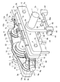
- the repeating moment generator 100 which is the first embodiment of the present invention, will be described with reference to FIGS. 1 to 3.
- the repetitive moment generator 100 is used for a fatigue tester (not shown) for testing fatigue strength characteristics by applying a repetitive moment to a specimen.
- the repetitive moment generator 100 has a spindle 1 for transmitting a repetitive moment to a specimen (not shown) set in the fatigue tester, and a predetermined distance on the upper surface of the table 24 for holding the spindle 1 rotatably.
- the shaft body 4 rotatably provided around the axis 4c and 5c (see FIG. 2) parallel to the spindle 1 at positions symmetrical with respect to the spindle 1 in the region where the rod members 3a and 3b face each other.
- 5 and eccentric weight rotors 6 and 7 that rotate together with the shaft bodies 4 and 5 around the shaft centers 4c and 5c.
- the eccentric weight rotors 6 and 7 have diameter-expanded portions 6b and 7b provided on a part of the shaft bodies 4 and 5, respectively, and axial centers 4c and 5c on the diameter-expanded portions 6b and 7b.
- the eccentric weight member 6c which is inserted through the through holes 6h and 7h opened in the orthogonal direction in a state orthogonal to the shaft bodies 4 and 5 and slidable along the direction orthogonal to the shaft bodies 4 and 5. It is equipped with 7c. Further, it is provided with a motor 14 which is a driving means for rotating the shaft bodies 4 and 5 in synchronization.
- the eccentric weight members 6c and 7c are stoppers provided in a short columnar shape having a diameter larger than the inner diameter of the through holes 6h and 7h at both ends of the columnar main body portions 6e and 7e and the main body portions 6e and 7e, respectively. 6f, 6g, 7f, 7g and so on.
- the main body portions 6e and 7e can slide in a state where the outer peripheral surfaces of the main bodies 6e and 7e are in contact with the inner peripheral surfaces of the through holes 6h and 7h, and the slide distances of the eccentric weight members 6c and 7c with respect to the shaft bodies 4 and 5 are stoppers, respectively.
- the length of the main body 6e, 7e is limited by 6f, 6g (7f, 7g).
- a spring which is an elastic member is formed around a portion located between one of the stoppers 6f and 7f and the enlarged diameter portions 6b and 7b of the shaft bodies 4 and 5.
- 6d and 7d are arranged, and both ends of the spring 6d (7d) are locked to the enlarged diameter portions 6b (7b) and the stopper 6f (7f), respectively.
- the spring 6d (7d) has the center of gravity of the eccentric weight member 6 (7) as the axis 4c of the shaft body 4 (5), respectively.
- the stopper 6f (7f) and the enlarged diameter portion 6b (7b) of the shaft body 4 (5) are connected so as to maintain the state of being located at 5c).
- a slider 30 is attached to the outer periphery of the portion between the lever members 3a and 3b on the spindle 1.
- the slider 30 is slidable along the axis 1c direction of the spindle 1, and the spindle 1 is idling with respect to the slider 30.
- a slider 31 (32) is attached to the outer periphery of a portion of the shaft body 4 (5) between the eccentric rotor 6 (7) and the lever member 3b.
- the slider 31 (32) can slide along the axis 4c (5c) direction of the shaft body 4 (5), and the shaft body 4 (5) can idle with respect to the slider 31 (32). be.
- an interlocking member 33 for integrally connecting the sliders 30, 31, 32 is provided.
- the interlocking member 33 is arranged at a portion between the eccentric weight rotors 6 and 7 and the lever member 3b so as to be orthogonal to the main shaft 1 and the shaft bodies 4 and 5 and to be parallel to the lever members 3a and 3b. ..
- the link mechanism 34 (35) includes a first link member 10 (12) and a second link member 11 (13).
- One end side of the first link member 10 (12) is rotatably supported by the support shaft 10a (12a) of the slider 31 (32), and the other end side is a stopper of the eccentric weight member 6c (7c). It is rotatably supported by a support shaft 10b (12b) of 6 g (7 g).
- One end side of the second link member 11 (13) is rotatably supported by the support shaft 11a (13a) of the enlarged diameter portion 6b (7b) of the shaft body 4 (5), and the other end side is It is rotatably supported by a support shaft 11b (13b) at the center of the first link member 10 (12).
- the link mechanisms 34 and 35 are displayed only on the upper surface side of the eccentric weight rotors 6 and 7, but as shown in the vicinity of the eccentric weight rotor 6 in FIG. 2, the link mechanism is partially displayed. 34 and 35 are also provided on the lower surface side of the eccentric weight rotors 6 and 7 shown in FIG. That is, the pair of link mechanisms 34, 34 (35, 35) are arranged so as to form mirror plane symmetry with the eccentric weight rotor 6 (7) interposed therebetween.
- the male screw member 37 is screwed into the female screw hole 36 provided below the slider 30 in a state of being parallel to the shaft bodies 4 and 5 and the spindle 1, and one of the male screw members 37 is screwed.
- the end portion (not shown) is rotatably held by a bearing member 43 arranged on the table 24 directly below the spindle 1.
- the other end side of the male screw member 37 is rotatably inserted into the through hole 38 provided in the spindle bearing member 2b, and the oblique tooth gear 39 is attached to the tip of the male screw member 37 protruding from the through hole 38. ing.
- the male screw member 37 is rotatably held by the through hole 38 of the bearing member 43 and the main bearing member 2b in a state where the movement of the male screw member 37 in the longitudinal direction is restricted.
- the bevel gear 39 is attached so as to be concentric with the male screw member 37, and the rotation shaft 40 on which the worm gear 40a is formed is arranged below the oblique tooth gear 39 so as to intersect the male screw member 37 at right angles.
- the oblique tooth gear 39 is meshed with the worm gear 40a.
- Both ends of the rotating shaft 40 are rotatably held by bearing members 41 and 42 arranged on the table 24, respectively, and a handle 44 is attached to the end of the rotating shaft 40 protruding from the bearing member 41.
- the rotation shaft 40 and the worm gear 40a rotate, and this rotation is transmitted to the oblique tooth gear 39, and the male screw member 37 rotates with the rotation of the oblique tooth gear 39 and is screwed with the male screw member 37.
- the slider 30 having the female screw hole 36 and the interlocking member 33 move in the longitudinal direction of the male screw member 37 (the axial center 1c direction of the main shaft 1).
- the sliders 31 and 32 integrated with the interlocking member 33 move in the axial center 4c and 5c directions of the shaft bodies 4 and 5, and the link mechanisms 34 and 35 operate.
- the sliders 31 and 32 integrated with the interlocking member 33 also slide in the direction away from the lever member 3b, and this sliding motion is caused by the stoppers 6g of the eccentric weight members 6c and 7c via the link mechanisms 34 and 35. It is transmitted to 7g, the stoppers 6g and 7g move in directions away from the enlarged diameter portions 6b and 7b of the shaft bodies 6 and 7, respectively, and the centers of gravity of the eccentric weight members 6c and 7c are the axial centers of the shaft bodies 4 and 5, respectively. Move away from 4c and 5c.
- the springs 6d and 7d arranged between the stoppers 6f and 7f of one of the eccentric weight members 6c and 7c and the enlarged diameter portions 6b and 7b of the shaft bodies 4 and 5 are eccentric weights.
- the stoppers 6f and 7f are connected to the shaft bodies 4 and 5 so as to maintain the state in which the centers of gravity of the members 6c and 7c are located at the shaft centers 4c and 5c of the shaft bodies 4 and 5.
- the eccentric weight members 6c and 7c are moved via the link mechanisms 34 and 35, the eccentric weight members 6c and 7c are subjected to the urging force by the springs 6d and 7d (the center of gravity of the eccentric weight members 6c and 7c). Since the force for returning to the positions of the centers of gravity 4c and 5c of the shaft bodies 4 and 5 continues to be applied, the discontinuous change in the torsional moment (effect of backlash) can be eliminated.
- the springs 6d and 7d may be used. Due to the elastic restoring force, the eccentric weight members 6c and 7c return to the state where their respective centers of gravity are located at the axial centers 4c and 5c of the shaft bodies 4 and 5 (zero eccentricity state), so that the so-called fail-safe function is also exhibited. do.
- the table 24 is a quadrangular flat plate-shaped member, and is kept in a horizontal state by four support members 25 arranged on the lower surface side of the four corner portions 24c.
- the support member 25 has an L-shaped horizontal cross section, and a bottom plate 25b is provided on the lower surface side.
- the four corner portions 24c of the table 24 are fixed in a state of being placed on the upper surface 25a of each of the four support members 25, and the quadrangular flat plate-shaped undertable 26 is arranged on the bottom plates 25b located at four locations. ..
- a motor 14 As a driving means for rotating the two eccentric weight rotors 6 and 7 in synchronization, a motor 14, medium timing pulleys 15 and 16, large timing pulley 18, small timing pulleys 19a and 19b, and timing belts 21 and 22 are provided. .. When the motor 14 operates, its rotational force is output to the rotating shaft 14a via the gearbox 17.
- a medium timing pulley 15 is attached to the rotating shaft 14a rotated by the motor 14, and a medium timing pulley 16 and a large timing pulley 18 are rotatably attached to the main shaft 1 via bearings.
- the rotating shaft 14a is parallel to the spindle 1, the middle timing pulley 15 on the motor 14 side is located directly below the middle timing pulley 16 on the spindle 1 side, and the middle timing pulleys 15 and 16 are in series in the vertical direction. They are arranged facing each other.
- Small timing pulleys 19a and 19b are attached to the shaft bodies 4 and 5.
- the small timing pulleys 19a and 19b are arranged so as to form a series with the large timing pulley 18 interposed therebetween.
- the sizes (outer diameters) of the small timing pulleys 19a and 19b are the same, and the sizes (outer diameters) of the medium timing pulleys 15 and 16 are also the same.
- the middle timing pulley 15 and the middle timing pulley 16 are linked by a timing belt 21, and the timing pulleys 19a and 19b and the large timing pulley 18 are linked by a timing belt 22.
- the middle timing pulley 15 integrally attached to the rotating shaft 14a rotates, and the rotation of the middle timing pulley 15 is transmitted to the middle timing pulley 16 via the timing belt 21.
- the pulley 16 rotates in the same direction as the rotation shaft 14a at the same rotation speed.
- the rotation of the middle timing pulley 16 is transmitted to the large timing pulley 18 integrated with the middle timing pulley 15 via the spindle 1.
- the shaft bodies 4 and 5 to which the small timing pulleys 19a and 19b are attached are in the same direction and at the same rotation speed. Rotate. Therefore, the two eccentric weight rotors 6 and 7 rotate in the same direction and at the same rotation speed in synchronization with each other. Further, the link mechanism 34, 35 and the sliders 31 and 32 rotate integrally with the rotation of the two eccentric weight rotors 6 and 7, but the slider 30 and the interlocking member 33 are held in a stationary state. In the repeating moment generator 100, the rotation center lines of the two eccentric weight rotors 6 and 7 are the same as the axis centers 4c and 5c of the shaft bodies 4 and 5, respectively.
- the two eccentric weight rotors 6 and 7 have the eccentric directions (directions of centrifugal forces 6a and 7a) of the centers of gravity of the eccentric weight members 6c and 7c, respectively. They are arranged so as to be 180 degrees different from each other around the centers of gravity 4c and 5c of the respective shaft bodies 4 and 5. Therefore, the two eccentric weight rotors 6 and 7 rotate while maintaining a relationship in which the directions of the centrifugal forces 6a and 7a differ from each other by 180 degrees around the rotation center lines (axis centers 4c and 5c).
- the eccentric weight rotors 6 and 5 are rotated by the driving force of the motor 14.
- the eccentric weight members 6c and 7c also rotate around the axial centers 4c and 5c, and centrifugal forces 6a and 7a having a magnitude determined by the eccentricity of the center of gravity of the eccentric weight members 6 and 7 and the number of rotations are generated. It occurs in the axial direction of the main bodies 6e and 7e. Since the direction in which the centrifugal forces 6a and 7a act is rotated around the axial centers 4c and 5c, the directions of the centrifugal forces 6a and 7a change up, down, left and right with the rotation.
- the sliders 30, 31 and 32 slide in the direction away from the lever member 3b, and the stoppers 6g and 7g are the shaft bodies via the link mechanisms 34 and 35. Since the center of gravity of the eccentric weight members 6c and 7c moves away from the center of gravity 4c and 5c of the shaft bodies 4 and 5, respectively, the eccentric weight rotor moves in a direction away from the enlarged diameter portions 6b and 7b of 6 and 7. The vibration generated by the rotations of 6 and 7 increases, and the amplitude of the repeating moment loaded on the spindle 1 via the lever members 3a and 3b increases.
- the handle 44 when the handle 44 is rotated in the direction of the arrow W1 and then the handle 44 is rotated in the direction opposite to the arrow W1, the male screw member 37 is inserted into the arrow via the worm gear 40a and the oblique tooth gear 39.
- the sliders 30, 31 and 32 move in the direction approaching the rod member 3b, and contrary to the above, the stoppers 6g and 7g are the enlarged diameter portions 6b and 7b of the shaft bodies 6 and 7, respectively. Since the center of gravity of the eccentric weight members 6c and 7c approaches the axis centers 4c and 5c of the shaft bodies 4 and 5, respectively, the vibration generated by the rotation of the eccentric weight rotors 6 and 7 is reduced. Then, the amplitude of the repeating moment loaded on the spindle 1 via the gear members 3a and 3b becomes smaller.
- the centers of gravity of the eccentric weight members 6c and 7c of the two eccentric weight rotors 6 and 7 are set at the positions (positions of zero amplitude) of the rotation center lines (axis centers 4c and 5c), respectively.
- the motor 14 can be started and the handle 44 can be operated during the rotation of the two eccentric weight rotors 6 and 7 to gradually increase the amplitude so that the optimum amplitude can be set. Can also be avoided.
- the repetitive moment generator 100 is used in combination with a torsion moment meter and an angle of rotation encoder, closed loop control becomes possible, and not only torsion moment control but also angular displacement control and program control can be used for testing, which is an advanced hydraulic system. It can be equipped with various control functions comparable to a fatigue tester at low cost.
- the repeating moment generator 100 shown in FIGS. 1 to 3 includes two shaft bodies 4 and 5, two eccentric weight rotors 6 and 7, and two sliders 31 for one spindle 1. 32 and two link mechanisms 34 and 35 are provided, and an amplitude adjusting mechanism is provided for each, but the present invention is not limited to this, and therefore one shaft body 4 (or one shaft body 4 (or) is provided for one spindle 1. 5), one eccentric weight rotor 6 (or 7), one slider 31 (or 32), and one link mechanism 34 (or 35) can also be provided. In this case as well, the same amplitude adjustment function as described above can be obtained.
- the repetitive moment generator 200 which is the second embodiment of the present invention, will be described with reference to FIG.
- the parts (members) constituting the repeating moment generating device 200 shown in FIG. 4 the parts (members) common to the repeating moment generating device 100 shown in FIGS. 1 to 3 are referred to as reference numerals in FIGS. 1 to 3.
- the same reference numerals are given and the description thereof will be omitted.
- the sliding motion of the shaft bodies 4 and 5 of the sliders 31 and 32 in the axial center 4c and 5c directions is performed by the shaft bodies 4 and 7c of the eccentric weight members 6c and 7c.
- Pulleys 50, 51 and wires 52, 53 are provided instead of the link mechanisms 34, 35 shown in FIG. 3 as connecting means that are converted into slide motions in the direction intersecting with 5 and transmitted to the eccentric weight members 6c, 7c. ing. Since the wires 52 and 53 are not limited to this, flexible wires, strings, chains and the like can be used as long as they have the same function.
- pulleys 50 and 51 are rotatably supported on the enlarged diameter portions 6b and 7b of the eccentric weight rotors 6 and 7, respectively, and the slider 31 (32) and the eccentric weight member 6c (7c) are supported. Is connected by a wire 52 (53) via a pulley 50 (51). One end of the wire 52 (53) is locked to the slider 31 (32), and the other end of the wire 52 (53) is locked to the stopper 6f (7f) of the eccentric weight member 6c (7c). ing.
- the structure, function, action and effect of other parts are the same as those of the above-mentioned repetitive moment generator 100.
- the repetitive moment generators 100 and 200 described with reference to FIGS. 1 to 4 exemplify the repetitive moment generator according to the present invention, and the repetitive moment generator according to the present invention is the repetitive moment generator described above. It is not limited to the generators 100 and 200.
- the repetitive moment generator according to the present invention can be widely used in a fatigue tester or the like that applies a repetitive moment to a specimen to test the fatigue strength characteristics of the specimen.
Landscapes
- Physics & Mathematics (AREA)
- General Physics & Mathematics (AREA)
- Health & Medical Sciences (AREA)
- Engineering & Computer Science (AREA)
- Life Sciences & Earth Sciences (AREA)
- Chemical & Material Sciences (AREA)
- Analytical Chemistry (AREA)
- Biochemistry (AREA)
- General Health & Medical Sciences (AREA)
- Mechanical Engineering (AREA)
- Immunology (AREA)
- Pathology (AREA)
- Investigating Strength Of Materials By Application Of Mechanical Stress (AREA)
- Apparatuses For Generation Of Mechanical Vibrations (AREA)
Abstract
Description
供試体に繰り返しモーメントを負荷して疲労強度特性を試験する疲労試験機に使用する繰り返しモーメント発生装置であって、
前記疲労試験機にセットされた供試体に繰り返しモーメントを伝達するため回転自在に保持された主軸と、
前記主軸の軸心方向に離れた位置にそれぞれ前記主軸と直交する状態で前記主軸に取り付けられた一対の梃子部材と、前記梃子部材が対向する領域において前記主軸を挟んで対称をなす位置にそれぞれ前記主軸と平行な軸心を中心に回転自在に保持された軸体と、
前記軸体を同期して回転させる駆動手段と、
前記軸体と交差する状態で且つ前記軸体と交差する方向に沿ってスライド可能な状態で前記軸体に取り付けられた偏心重錘部材と、
前記軸体の軸心方向に沿って摺動可能な状態で且つ前記軸体が空転可能な状態で前記軸体に取り付けられたスライダと、
前記スライダの前記軸体の軸心方向の摺動運動を、前記偏心重錘部材の前記軸体と交差する方向のスライド運動に変換して前記偏心重錘部材に伝達する連接手段と、
前記スライダを前記軸体の軸心方向に沿って摺動させる操作手段と、を備えたことを特徴とする。
前記連接手段は、
一方の端部側が前記スライダに回動可能に軸支され、他方の端部側が前記偏心重錘部材に回動可能に軸支された第一リンク部材と、
一方の端部側が前記軸体に回動可能に軸支され、他方の端部側が前記第一リンク部材に回動可能に軸支された第二リンク部材と、を備えたリンク機構とすることができる。
前記連接手段は、
前記スライダと前記偏心重錘部材とを、前記軸体に回動可能に軸支されたプーリを経由して連結するワイヤであってもよい。
前記軸体に対する前記偏心重錘部材のスライド距離を所定範囲に制限するストッパを前記偏心重錘部材に設けることができる。
前記偏心重錘部材の一方のストッパと前記軸体との間に、前記偏心重錘部材の重心が前記軸体の軸心に位置する状態を保持するように前記ストッパと前記軸体とを連結する弾性部材を配置することもできる。
前記操作手段は、
前記スライダに開設された雌ネジ孔に前記軸体と平行をなす状態で螺合された雄ネジ部材と、
前記雄ネジ部材を、前記雄ネジ部材の長手方向の移動を拘束した状態で回動可能に保持する軸受け部材と、
前記雄ネジ部材を回動させる回動機構と、を備えたものとすることができる。
前記回動機構は、
前記雄ネジ部材と同心をなすように前記雄ネジ部材に取り付けられた斜歯ギアと、
前記斜歯ギアに噛合されたウォームギアと、
前記ウォームギアを回動させるハンドルと、を備えたものとすることができる。
2a,2b 主軸受け部材
3a,3b 梃子部材
4,5 軸体
1c,4c,5c 軸心
6,7 偏心重錘ロータ
6a,7a 遠心力
6b,7b 拡径部
6c,7c 偏心重錘部材
6d,7d スプリング
6e,7e 本体部
6f,6g,7f,7g ストッパ
6h,7h,38 貫通孔
14 モータ
14a 回転軸
15,16 中タイミングプーリ
17 ギアボックス
18 大タイミングプーリ
19a,19b 小タイミングプーリ
21,22 タイミングベルト
24 テーブル
24a 上面
24b 下面
24c コーナ部
25 支持部材
25a 上面
25b 底板
26 アンダーテーブル
30,31,32 スライダ
33 連動部材
34,35 リンク機構
36 雌ネジ孔
37 雄ネジ部材
39 斜歯ギア
40 回転軸
40a ウォームギア
41,42,43 軸受け部材
44 ハンドル
50,51 プーリ
52,53 ワイヤ
100,200 繰り返しモーメント発生装置
Claims (7)
- 供試体に繰り返しモーメントを負荷して疲労強度特性を試験する疲労試験機に使用する繰り返しモーメント発生装置であって、
前記疲労試験機にセットされた供試体に繰り返しモーメントを伝達するため回転自在に保持された主軸と、
前記主軸の軸心方向に離れた位置にそれぞれ前記主軸と直交する状態で前記主軸に取り付けられた一対の梃子部材と、前記梃子部材が対向する領域において前記主軸を挟んで対称をなす位置にそれぞれ前記主軸と平行な軸心を中心に回転自在に保持された軸体と、
前記軸体を同期して回転させる駆動手段と、
前記軸体と交差する状態で且つ前記軸体と交差する方向に沿ってスライド可能な状態で前記軸体に取り付けられた偏心重錘部材と、
前記軸体の軸心方向に沿って摺動可能な状態で且つ前記軸体が空転可能な状態で前記軸体に取り付けられたスライダと、
前記スライダの前記軸体の軸心方向の摺動運動を、前記偏心重錘部材の前記軸体と交差する方向のスライド運動に変換して前記偏心重錘部材に伝達する連接手段と、
前記スライダを前記軸体の軸心方向に沿って摺動させる操作手段と、を備えた繰り返しモーメント発生装置。 - 前記連接手段が、
一方の端部側が前記スライダに回動可能に軸支され、他方の端部側が前記偏心重錘部材に回動可能に軸支された第一リンク部材と、
一方の端部側が前記軸体に回動可能に軸支され、他方の端部側が前記第一リンク部材に回動可能に軸支された第二リンク部材と、を備えたリンク機構である請求項1記載の繰り返しモーメント発生装置。 - 前記連接手段が、
前記スライダと前記偏心重錘部材とを、前記軸体に回動可能に軸支されたプーリを経由して連結するワイヤである請求項1記載の繰り返しモーメント発生装置。 - 前記軸体に対する前記偏心重錘部材のスライド距離を所定範囲に制限するストッパを前記偏心重錘部材に設けた請求項1または2記載の繰り返しモーメント発生装置。
- 前記偏心重錘部材の一方のストッパと前記軸体との間に、前記偏心重錘部材の重心が前記軸体の軸心に位置する状態を保持するように前記ストッパと前記軸体とを連結する弾性部材を配置した請求項1~4の何れかの項に記載の繰り返しモーメント発生装置。
- 前記操作手段が、
前記スライダに開設された雌ネジ孔に前記軸体と平行をなす状態で螺合された雄ネジ部材と、
前記雄ネジ部材を、前記雄ネジ部材の長手方向の移動を拘束した状態で回動可能に保持する軸受け部材と、
前記雄ネジ部材を回動させる回動機構と、を備えた請求項1~5の何れかの項に記載の繰り返しモーメント発生装置。 - 前記回動機構が、
前記雄ネジ部材と同心をなすように前記雄ネジ部材に取り付けられた斜歯ギアと、
前記斜歯ギアに噛合されたウォームギアと、
前記ウォームギアを回動させるハンドルと、を備えた請求項6記載の繰り返しモーメント発生装置。
Priority Applications (2)
| Application Number | Priority Date | Filing Date | Title |
|---|---|---|---|
| EP21833039.7A EP4176979B1 (en) | 2020-07-02 | 2021-06-30 | Repetitive moment generating device |
| US18/088,471 US12292417B2 (en) | 2020-07-02 | 2022-12-23 | Repetitive moment generating device |
Applications Claiming Priority (2)
| Application Number | Priority Date | Filing Date | Title |
|---|---|---|---|
| JP2020114995A JP7442809B2 (ja) | 2020-07-02 | 2020-07-02 | 繰り返しモーメント発生装置 |
| JP2020-114995 | 2020-07-02 |
Related Child Applications (1)
| Application Number | Title | Priority Date | Filing Date |
|---|---|---|---|
| US18/088,471 Continuation US12292417B2 (en) | 2020-07-02 | 2022-12-23 | Repetitive moment generating device |
Publications (1)
| Publication Number | Publication Date |
|---|---|
| WO2022004793A1 true WO2022004793A1 (ja) | 2022-01-06 |
Family
ID=79316308
Family Applications (1)
| Application Number | Title | Priority Date | Filing Date |
|---|---|---|---|
| PCT/JP2021/024768 Ceased WO2022004793A1 (ja) | 2020-07-02 | 2021-06-30 | 繰り返しモーメント発生装置 |
Country Status (4)
| Country | Link |
|---|---|
| US (1) | US12292417B2 (ja) |
| EP (1) | EP4176979B1 (ja) |
| JP (1) | JP7442809B2 (ja) |
| WO (1) | WO2022004793A1 (ja) |
Citations (7)
| Publication number | Priority date | Publication date | Assignee | Title |
|---|---|---|---|---|
| JPS5099784A (ja) * | 1973-12-31 | 1975-08-07 | ||
| JPH11156296A (ja) | 1997-11-21 | 1999-06-15 | K:Kk | 可変型振動テーブル用振動装置 |
| JPH11511552A (ja) * | 1995-08-22 | 1999-10-05 | ザ ビー.エフ.グッドリッチ カンパニー | 粘弾性物質のテストシステム |
| JP2007107955A (ja) | 2005-10-12 | 2007-04-26 | Ntn Corp | 捩り疲労試験機 |
| JP2011064508A (ja) * | 2009-09-15 | 2011-03-31 | Fukuoka Univ | 疲労試験機 |
| JP2018036191A (ja) * | 2016-09-01 | 2018-03-08 | 新日鐵住金株式会社 | 疲労試験装置及び疲労試験方法 |
| JP2020056706A (ja) * | 2018-10-03 | 2020-04-09 | 日本製鉄株式会社 | き裂進展評価方法 |
Family Cites Families (9)
| Publication number | Priority date | Publication date | Assignee | Title |
|---|---|---|---|---|
| FR1018538A (fr) * | 1949-05-24 | 1953-01-08 | Procédé pour la vibration à fréquences variables de matière finement divisée et appareils vibratoires permettant d'appliquer ce procédé | |
| DE2236695C3 (de) * | 1972-07-26 | 1975-04-17 | Wacker-Werke Kg, 8000 Muenchen | Vorrichtung zur stufenlosen Änderung der Zentrifugalkraft, insbesondere für Vibrations-Erzeuger |
| DE2742289A1 (de) * | 1977-09-20 | 1979-03-29 | Schlosser & Co Gmbh | Schwingungserreger, insbesondere fuer verdichtungsruettler |
| NZ194594A (en) * | 1979-09-06 | 1984-08-24 | Rexnord Inc | Directionally variable vibration generator |
| US5458002A (en) | 1994-05-16 | 1995-10-17 | The B. F. Goodrich Company | Viscoelastic material testing system |
| US6321610B1 (en) * | 1999-08-08 | 2001-11-27 | Kabushiki Kaisha Kei | Vibration apparatus for a variable amplitude type vibration table |
| CN1676759A (zh) * | 2005-04-27 | 2005-10-05 | 冯忠绪 | 多频合成振动压实方法及压实机用多频合成激振器 |
| CN110631815B (zh) * | 2019-09-26 | 2024-12-10 | 河北宏光供电器材有限公司 | 定位器振动疲劳试验机 |
| EP4134653B1 (en) * | 2020-04-08 | 2024-11-20 | Fukuoka University | Repeated moment generation device |
-
2020
- 2020-07-02 JP JP2020114995A patent/JP7442809B2/ja active Active
-
2021
- 2021-06-30 EP EP21833039.7A patent/EP4176979B1/en active Active
- 2021-06-30 WO PCT/JP2021/024768 patent/WO2022004793A1/ja not_active Ceased
-
2022
- 2022-12-23 US US18/088,471 patent/US12292417B2/en active Active
Patent Citations (7)
| Publication number | Priority date | Publication date | Assignee | Title |
|---|---|---|---|---|
| JPS5099784A (ja) * | 1973-12-31 | 1975-08-07 | ||
| JPH11511552A (ja) * | 1995-08-22 | 1999-10-05 | ザ ビー.エフ.グッドリッチ カンパニー | 粘弾性物質のテストシステム |
| JPH11156296A (ja) | 1997-11-21 | 1999-06-15 | K:Kk | 可変型振動テーブル用振動装置 |
| JP2007107955A (ja) | 2005-10-12 | 2007-04-26 | Ntn Corp | 捩り疲労試験機 |
| JP2011064508A (ja) * | 2009-09-15 | 2011-03-31 | Fukuoka Univ | 疲労試験機 |
| JP2018036191A (ja) * | 2016-09-01 | 2018-03-08 | 新日鐵住金株式会社 | 疲労試験装置及び疲労試験方法 |
| JP2020056706A (ja) * | 2018-10-03 | 2020-04-09 | 日本製鉄株式会社 | き裂進展評価方法 |
Non-Patent Citations (1)
| Title |
|---|
| See also references of EP4176979A4 |
Also Published As
| Publication number | Publication date |
|---|---|
| JP2022012863A (ja) | 2022-01-17 |
| US20230129401A1 (en) | 2023-04-27 |
| US12292417B2 (en) | 2025-05-06 |
| EP4176979A4 (en) | 2023-12-13 |
| JP7442809B2 (ja) | 2024-03-05 |
| EP4176979B1 (en) | 2025-06-25 |
| EP4176979A1 (en) | 2023-05-10 |
Similar Documents
| Publication | Publication Date | Title |
|---|---|---|
| JP5387775B2 (ja) | 関節装置の駆動方法 | |
| JP4388566B2 (ja) | 立体カム機構 | |
| JP6110620B2 (ja) | パラレルリンクロボット | |
| RU2710314C1 (ru) | Способ изменения и настройки динамического состояния вибрационной технологической машины и устройство для его осуществления | |
| Legnani et al. | Harmonic drive transmissions: the effects of their elasticity, clearance and irregularity on the dynamic behaviour of an actual SCARA robot | |
| JP7442809B2 (ja) | 繰り返しモーメント発生装置 | |
| JP5760263B2 (ja) | 無段変速機及びロボット関節構造 | |
| JP7604010B2 (ja) | 繰り返しモーメント発生装置 | |
| JPS59169791A (ja) | マニプレ−タの少なくとも1つの主要な軸のための遊びなく調節可能な旋回駆動装置 | |
| KR102330033B1 (ko) | 감속기 내구성능 평가 장치 | |
| JP5119394B2 (ja) | 可変減速機 | |
| US10272562B2 (en) | Parallel kinematics robot with rotational degrees of freedom | |
| GB2527064A (en) | A reaction producing device that makes use of gyroscopic rotation to reset a reactive mass | |
| CN102626922B (zh) | 四支链二维平动一维转动自由度并联机械手 | |
| JPH10339693A (ja) | シート状試料の曲げ特性測定装置 | |
| CZ2010234A3 (cs) | Zpusob a zarízení ke snížení negativních úcinku dynamických sil mechanické soustavy | |
| JP2012067809A (ja) | 無段変速機 | |
| JP2010264515A (ja) | 揺動装置 | |
| JP3109489B2 (ja) | 多軸駆動機構 | |
| Suzuki et al. | Design Principle and Analysis of an Output Cam for a Rotary Actuator Capable of Multidirectional Rapid Motion and Variable Stiffness | |
| TWI264629B (en) | Motion adjustable standard cam system | |
| US20250230864A1 (en) | Rotary actuator unit, and joint unit for robot or heavy equipment provided with same | |
| RU2185897C2 (ru) | Кривошип с переменным радиусом | |
| KR200489395Y1 (ko) | 축 이동을 이용한 편심회전체 위상제어 진동발생기 | |
| JPH0453674B2 (ja) |
Legal Events
| Date | Code | Title | Description |
|---|---|---|---|
| 121 | Ep: the epo has been informed by wipo that ep was designated in this application |
Ref document number: 21833039 Country of ref document: EP Kind code of ref document: A1 |
|
| WWE | Wipo information: entry into national phase |
Ref document number: 202317006134 Country of ref document: IN |
|
| WWE | Wipo information: entry into national phase |
Ref document number: 2021833039 Country of ref document: EP |
|
| ENP | Entry into the national phase |
Ref document number: 2021833039 Country of ref document: EP Effective date: 20230202 |
|
| NENP | Non-entry into the national phase |
Ref country code: DE |
|
| WWG | Wipo information: grant in national office |
Ref document number: 2021833039 Country of ref document: EP |