WO2022006112A1 - Systems and methods for high reactant conversion through multiple reactant flow ratio staging - Google Patents
Systems and methods for high reactant conversion through multiple reactant flow ratio staging Download PDFInfo
- Publication number
- WO2022006112A1 WO2022006112A1 PCT/US2021/039622 US2021039622W WO2022006112A1 WO 2022006112 A1 WO2022006112 A1 WO 2022006112A1 US 2021039622 W US2021039622 W US 2021039622W WO 2022006112 A1 WO2022006112 A1 WO 2022006112A1
- Authority
- WO
- WIPO (PCT)
- Prior art keywords
- gas
- reactor
- inlet
- outlet
- stream
- Prior art date
- Legal status (The legal status is an assumption and is not a legal conclusion. Google has not performed a legal analysis and makes no representation as to the accuracy of the status listed.)
- Ceased
Links
Classifications
-
- B—PERFORMING OPERATIONS; TRANSPORTING
- B01—PHYSICAL OR CHEMICAL PROCESSES OR APPARATUS IN GENERAL
- B01J—CHEMICAL OR PHYSICAL PROCESSES, e.g. CATALYSIS OR COLLOID CHEMISTRY; THEIR RELEVANT APPARATUS
- B01J6/00—Heat treatments such as Calcining; Fusing ; Pyrolysis
- B01J6/008—Pyrolysis reactions
-
- B—PERFORMING OPERATIONS; TRANSPORTING
- B01—PHYSICAL OR CHEMICAL PROCESSES OR APPARATUS IN GENERAL
- B01J—CHEMICAL OR PHYSICAL PROCESSES, e.g. CATALYSIS OR COLLOID CHEMISTRY; THEIR RELEVANT APPARATUS
- B01J15/00—Chemical processes in general for reacting gaseous media with non-particulate solids, e.g. sheet material; Apparatus specially adapted therefor
-
- B—PERFORMING OPERATIONS; TRANSPORTING
- B01—PHYSICAL OR CHEMICAL PROCESSES OR APPARATUS IN GENERAL
- B01J—CHEMICAL OR PHYSICAL PROCESSES, e.g. CATALYSIS OR COLLOID CHEMISTRY; THEIR RELEVANT APPARATUS
- B01J4/00—Feed or outlet devices; Feed or outlet control devices
- B01J4/008—Feed or outlet control devices
-
- B—PERFORMING OPERATIONS; TRANSPORTING
- B01—PHYSICAL OR CHEMICAL PROCESSES OR APPARATUS IN GENERAL
- B01J—CHEMICAL OR PHYSICAL PROCESSES, e.g. CATALYSIS OR COLLOID CHEMISTRY; THEIR RELEVANT APPARATUS
- B01J7/00—Apparatus for generating gases
-
- B—PERFORMING OPERATIONS; TRANSPORTING
- B01—PHYSICAL OR CHEMICAL PROCESSES OR APPARATUS IN GENERAL
- B01J—CHEMICAL OR PHYSICAL PROCESSES, e.g. CATALYSIS OR COLLOID CHEMISTRY; THEIR RELEVANT APPARATUS
- B01J8/00—Chemical or physical processes in general, conducted in the presence of fluids and solid particles; Apparatus for such processes
- B01J8/0015—Feeding of the particles in the reactor; Evacuation of the particles out of the reactor
- B01J8/003—Feeding of the particles in the reactor; Evacuation of the particles out of the reactor in a downward flow
-
- B—PERFORMING OPERATIONS; TRANSPORTING
- B01—PHYSICAL OR CHEMICAL PROCESSES OR APPARATUS IN GENERAL
- B01J—CHEMICAL OR PHYSICAL PROCESSES, e.g. CATALYSIS OR COLLOID CHEMISTRY; THEIR RELEVANT APPARATUS
- B01J8/00—Chemical or physical processes in general, conducted in the presence of fluids and solid particles; Apparatus for such processes
- B01J8/08—Chemical or physical processes in general, conducted in the presence of fluids and solid particles; Apparatus for such processes with moving particles
-
- B—PERFORMING OPERATIONS; TRANSPORTING
- B22—CASTING; POWDER METALLURGY
- B22F—WORKING METALLIC POWDER; MANUFACTURE OF ARTICLES FROM METALLIC POWDER; MAKING METALLIC POWDER; APPARATUS OR DEVICES SPECIALLY ADAPTED FOR METALLIC POWDER
- B22F1/00—Metallic powder; Treatment of metallic powder, e.g. to facilitate working or to improve properties
- B22F1/14—Treatment of metallic powder
- B22F1/145—Chemical treatment, e.g. passivation or decarburisation
-
- B—PERFORMING OPERATIONS; TRANSPORTING
- B22—CASTING; POWDER METALLURGY
- B22F—WORKING METALLIC POWDER; MANUFACTURE OF ARTICLES FROM METALLIC POWDER; MAKING METALLIC POWDER; APPARATUS OR DEVICES SPECIALLY ADAPTED FOR METALLIC POWDER
- B22F9/00—Making metallic powder or suspensions thereof
- B22F9/16—Making metallic powder or suspensions thereof using chemical processes
- B22F9/18—Making metallic powder or suspensions thereof using chemical processes with reduction of metal compounds
- B22F9/20—Making metallic powder or suspensions thereof using chemical processes with reduction of metal compounds starting from solid metal compounds
- B22F9/22—Making metallic powder or suspensions thereof using chemical processes with reduction of metal compounds starting from solid metal compounds using gaseous reductors
-
- B—PERFORMING OPERATIONS; TRANSPORTING
- B01—PHYSICAL OR CHEMICAL PROCESSES OR APPARATUS IN GENERAL
- B01J—CHEMICAL OR PHYSICAL PROCESSES, e.g. CATALYSIS OR COLLOID CHEMISTRY; THEIR RELEVANT APPARATUS
- B01J2208/00—Processes carried out in the presence of solid particles; Reactors therefor
- B01J2208/00008—Controlling the process
- B01J2208/00628—Controlling the composition of the reactive mixture
-
- B—PERFORMING OPERATIONS; TRANSPORTING
- B01—PHYSICAL OR CHEMICAL PROCESSES OR APPARATUS IN GENERAL
- B01J—CHEMICAL OR PHYSICAL PROCESSES, e.g. CATALYSIS OR COLLOID CHEMISTRY; THEIR RELEVANT APPARATUS
- B01J2208/00—Processes carried out in the presence of solid particles; Reactors therefor
- B01J2208/00743—Feeding or discharging of solids
- B01J2208/00761—Discharging
-
- B—PERFORMING OPERATIONS; TRANSPORTING
- B22—CASTING; POWDER METALLURGY
- B22F—WORKING METALLIC POWDER; MANUFACTURE OF ARTICLES FROM METALLIC POWDER; MAKING METALLIC POWDER; APPARATUS OR DEVICES SPECIALLY ADAPTED FOR METALLIC POWDER
- B22F2201/00—Treatment under specific atmosphere
- B22F2201/01—Reducing atmosphere
- B22F2201/013—Hydrogen
-
- B—PERFORMING OPERATIONS; TRANSPORTING
- B22—CASTING; POWDER METALLURGY
- B22F—WORKING METALLIC POWDER; MANUFACTURE OF ARTICLES FROM METALLIC POWDER; MAKING METALLIC POWDER; APPARATUS OR DEVICES SPECIALLY ADAPTED FOR METALLIC POWDER
- B22F2201/00—Treatment under specific atmosphere
- B22F2201/04—CO or CO2
-
- B—PERFORMING OPERATIONS; TRANSPORTING
- B22—CASTING; POWDER METALLURGY
- B22F—WORKING METALLIC POWDER; MANUFACTURE OF ARTICLES FROM METALLIC POWDER; MAKING METALLIC POWDER; APPARATUS OR DEVICES SPECIALLY ADAPTED FOR METALLIC POWDER
- B22F2302/00—Metal Compound, non-Metallic compound or non-metal composition of the powder or its coating
- B22F2302/25—Oxide
Definitions
- the present disclosure is related to reactor configurations for gas-solid reactions with multiple potential products to facilitate generation of one or more target products.
- a reactor design for gas-solid reaction with one or more additional outlet for gas or solid phase is provided.
- a reactor design for gas-solid reaction with one or more additional outlet for gas and solid phases is described.
- the design for a gas-solid reactor with one side inlet and two outlets for gas phase is described.
- a reactor design with pairs of inlet and outlet for both gas and solid phase is provided.
- a reactor design with one or more side inlets but only one outlet for gas phase is provided.
- a reactor design with two inlets at the top/bottom of reactor and two side outlets for gaseous phase is described.
- a reactor design with one or more side inlets and outlets for both gas and solid phases is provided.
- a modular reactor system with modules as individual reactor configurations in parallel and/or sequence is described.
- the reactor configurations with staged inlets and outlets disclosed here uses side inlets and outlets on the reactor to affect conditions under thermodynamic equilibrium as well as the heat balance of reactor.
- the reactor is designed and can be adjusted to convert gaseous and solid feedstocks to the desired product.
- the present disclosure details arrangements and designs for individual gas-solid reactor configurations, involving the relative flow direction of gas and solid phase, the transfer direction of O, side outlet product recycle, etc.
- Figure 1 shows the phase diagram of the gas-solid reaction example in this disclosure.
- Figures 2A and 2B show the phase diagram and operating lines (represented by the lighter colored lines) of the example gas-solid reactions within a counter-current reactor.
- Figures 3 A-3H show configurations using one inlet for both the gas and solid phases and two or multiple outlets for one of the gas or solid phases.
- Figures 4A and 4B show phase diagrams and operating lines of certain configurations shown in Figures 3 A and 3E, respectively.
- Figures 5A-5H show configurations using one inlet and two or multiple outlets for both the gas and solid streams.
- Figures 6A-6D show configurations using one side inlet and two outlets at the two ends of the reactor for the gas phase.
- Figures 7A-7H show configurations using two inlet-and-outlet pairs for the gas phase and one inlet-and-outlet pair for the solid phase.
- Figures 8A-8H show configurations using two inlet-and-outlet pairs for the solid phase and one inlet-and-outlet pair for the gas phase.
- Figures 9A-9D show configurations with multiple gas inlets and one gas outlet.
- Figures 10A-10D show configurations with a gas inlet from both the top and the bottom of the reactor and gas outlet from the side.
- Figures 11 A-l ID show configurations with a solid inlet from both the top and the bottom and outlet from the side.
- Figures 12A-12D show counter-current reactor configurations with multiple side inlets and outlets for both gas and solid phases, considering the transfer direction of O and recycle of product from side outlet.
- Figures 13A-13D show co-current reactor configurations with multiple side inlets and outlets for both gas and solid phases, considering the transfer direction of O and recycle of product from side outlet.
- Figures 14A and 14B show a schematic layout of shaft furnace designs with and without a side outlet.
- Figures 15A and 15B show flow diagrams of the chemical looping Fh production system which utilizes the strategy of multiple gas phase inlets.
- Figure 16A is a schematic illustration of gas-solid contact for a conventional shaft furnace design.
- Figure 16B is a schematic illustration of gas-solid contact for an exemplary shaft furnace design consistent with certain embodiments of the disclosure.
- systems and methods disclosed herein relate to reactor design and operation strategies that can overcome inherent thermodynamic limits, which may improve product quality and/or reduce the number of operation units.
- Certain objectives of gas-solid reactors can be divided into two categories: one is aiming to achieve a certain product composition of the solid, and the other one is to obtain a specific composition in the gaseous effluent. In both cases, the maximum gas-solid conversions are inherently dictated by the thermodynamics.
- intermediate products e.g., reduction/oxidation of metal oxides where the metal has more than two valence states
- the equilibrium composition at the product outlets might not meet the requirement to be directly collected or to be further utilized in the downstream process.
- a four-stage gas-solid reaction carried out in a moving-bed reactor is herein used as an example throughout this disclosure.
- the instant disclosure provides various operating strategies that can overcome inherent thermodynamic limitations within gas-solid reactor systems. These operating strategies can involve the use of multiple locations of injection into and/or extraction from the gas-solid reactor to circumvent the conversion limits imposed by thermodynamic equilibrium. Exemplary operating strategies may result in higher quality, purity, and/or yield of the product, and/or lower energy consumption associated with purification, compression and recycling.
- Exemplary approaches can be applied to various gas-solid reactor systems, such as shaft furnace ironmaking and chemical looping H2 production, where the conversions of both the gas and solid outlets are desired to be high but are restricted by thermodynamic equilibrium.
- This approach can be utilized in such systems to achieve higher gas and/or solid conversions that are not achievable in a system with one gas outlet and one solid outlet (which may result in higher product yield, energy savings, and economic benefits).
- Solid phases can include one or multiple metals and/or their compounds, which can include but are not limited to oxidizes, sulfides, halides, sulfates, carbonates, etc.
- Gas phases can include any organic or inorganic, combustible or non-combustible species, including but not limited to Eb, CO, CEE, or a mixture thereof.
- the substance that is transferred between the gas and solid phases, represented by O can be any element, including but not limited to oxygen, sulfur, nitrogen; or any compound, including but not limited to CO2, SO2.
- the gas-solid reaction can hence be redox or non-redox.
- Figure 1 presents the equilibrium phase diagram of an example gas-solid reaction where the gas and solid phases swing, respectively, from BO m to BO m+cr and AO x to AO x-s>
- four different valence states of A can exist in the solid phase during the reaction, which results in the following four AO compounds: AO x , AO c-di , A0 x _g 2 , and AO x-s> .
- the operating curves which are derived from mass balance and are restricted by thermodynamic equilibrium, can be used to determine the gas and solids conversions.
- FIG. 2A illustrates a process where a specific solid composition is targeted (i.e., AO c-da ), in which the operating line indicates that the collected gaseous product ( BO n ) is in a mixture form of BO m and BO m+cr .
- This mixture gaseous product could dramatically reduce the overall process efficiency if a pure product stream ( BO m+cr ) is demanded, because of the requirement of adding capital-intensive air separation units and/or post-combustion units in the downstream.
- BO m+cr the corresponding solid composition at the outlet is inherently fixed at AO x-Sb as indicated in Figure 2B.
- FIG. l is a phase diagram of the exampled gas-solid reaction adopted in this disclosure.
- Figure 2 is a phase diagram and operating lines (represented by the lighter lines) of the example gas-solid reaction within a counter-current reactor where in FIG. 2 A the solid product composition is targeted at AO x-a , and in FIG. 2B the gas product composition is targeted at BO m+cr .
- reactor configurations include, but are not limited to: a reactor with one inlet for the gas phase, one inlet for the solid phase, and either one of the gas or solid phases with multiple outlets, and the other phase with one outlet; a reactor with one inlet for the gas phase, one inlet for the solid phase, and multiple outlets for both the gas and the solid phases; a reactor with one inlet and one outlet for the solid phase, and one inlet for the gas phase at the side, and two outlets for the gas phase at the top and the bottom of the reactor; a reactor with multiple inlets and multiple outlets for one phase (gas or solid), and one inlet and one outlet for the other phase; a reactor with one solid inlet, one solid outlet, multiple gas inlets and one gas outlet; a reactor with the injection of one phase (gas
- Figure 3 shows configurations of using one inlet for both the gas and solid phases with two or multiple outlets for one phase.
- adding one or more reactant outlets for the gas or solid phase in a counter-current reactor, while maintaining the unmanipulated phase as a single outlet can result in the composition of the reactants exiting one of the added outlets to be fully converted while maintaining the target conversion of the unmanipulated phase.
- a similar approach can be applied to co-current reactors as shown in Figures 3E-3H, which enables multiple outlets of the manipulated phase to have different product compositions while maintaining the product composition of the unmanipulated phase unaffected, thereby increasing the process flexibility.
- FIG 4A schematically depicts a phase diagram for the counter-current reactor configuration of Figure 3 A.
- adding a side outlet creates two sections with different gas- to-solid ratios, which prevents the operating lines from intercepting the equilibrium lines.
- an operating window for the top gas outlet i.e., k ⁇ n ⁇ m + s
- BO m+cr fully converted gaseous product
- An exemplary application is a shaft furnace reactor for the production of direct reduced iron (DRI) from iron ore and reducing gas, commonly syngas (CO and Fh).
- the shaft furnace is operated as a counter-current moving bed, corresponding to the configuration shown in Figure 3 A, where pelletized iron ore is moving downward while syngas flows upward.
- DRI is produced at the bottom of the furnace.
- O stands for oxygen atom
- the reactant in solid phase is iron oxide
- the reactants in gas phase are CO and Fh.
- the unreacted syngas coming out from the top of the furnace requires conditioning equipment, including mainly compression and CO2 removal, to be recycled as the reducing gas of the shaft furnace or combusted to provide heat.
- the configuration shown in Figure 3 A can be adopted to allow one or more side outlet for the unreacted syngas.
- the solid to gas ratio beyond the side outlet will be higher than that below the side outlet, resulting in production of CO2 and H2O from full combustion of syngas.
- the amount of gas from the side gas outlet is less than that of gas coming out from the top of shaft furnace before the adoption of this disclosure, which reduces the size of conditioning equipment and the energy consumption of compression.
- the cost and energy consumption associated with CO2 removal may be lower for the design with two gas outlets compared to one gas outlet.
- FIG. 5 shows configurations of using one inlet and two or multiple outlets for both the gas and solid streams.
- Figures 6A-6D show configurations of using one side inlet, one top and bottom outlets for the gas phase.
- the gas inlet is introduced to the side of the reactor, resulting the gas stream split into two outlets respectively at the top and the bottom of the reactor as exemplified in Figure 6A and 6B.
- the gas product composition of the counter-current section can be varied, including a fully converted gaseous product ( BO m+cr ). This embodiment holds whether 0 is transferred from the solid to the gas phase or vice versa.
- the gaseous effluent of the co-current contact section which is a mixture of BO m and BO m+cr , can be further recycled/reused as shown in Figure 6C and 6D.
- two inlet-and-outlet pairs are designed for one phase while the other phase remains with one inlet-and-outlet pair.
- Figures 7A-7H show configurations of using two inlet-and-outlet pairs for the gas phase and one inlet-and-outlet pair for the solid phase.
- Figures 8A-8H show configurations of using two inlet-and-outlet pairs for the solid phase and one inlet- and-outlet pair for the gas phase.
- the inlet and outlet of one pair are located respectively at one end and side of the reactor, whereas the other pair has the opposite order.
- a counter-current and a co-current gas-solid contacts can be created at different sections within a counter-current reactor, while two co-current sections with different gas-to-solid ratio can be obtained in a co-current reactor.
- These configurations hold whether O is transferred from the solid to the gas phase or vice versa. If necessary, the outlet streams of the phase with two pairs of inlet and outlet can be further recycled/reused.
- Figures 9A-9D show four exemplary arrangements of the gas and solid flow of the system where the reactor is operated with a solid inlet and a gas inlet, which flow in either a counter-current or co-current pattern.
- the solid inlet stream is injected from the top of the reactor and leaves the reactor at the bottom.
- the gas inlet is injected from the bottom of the bed in the counter-current operating mode and is injected from the top of the bed in the co-current operating mode.
- An additional gas stream or multiple gas streams are injected from the side of the reactor.
- Figure 9A shows the configuration where the solid and gas react in a counter-current contact pattern where O is transferred from the solid to the gas.
- Figure 9B shows another configuration with counter-current gas-solid flow pattern where O is transferred from the gas to the solid.
- Figures 9C and 9D show the configurations where the solid and gas flow in a co-current contact pattern. In Figure 9C, O is transferred from the solid to the gas. In Figure 9D, O is transferred from the gas to the
- FIG. 9A-9D A specific application of embodiments shown in Figures 9A-9D is in the reducer operation of chemical looping Fh production.
- the reducer of the chemical looping Fh production process corresponds to Figure 9A, which operates under a counter-current gas-solid contact pattern, where the solid is reduced and the gas is oxidized.
- O stands for oxygen atoms.
- An objective of the reducer of the chemical looping H2 production process is to fully oxidize one or multiple reducing gas streams into CO2 and H2O, while reducing the metal oxide to an oxidation degree sufficiently low in order to facilitate the subsequent water splitting reaction in the oxidizer.
- Figures 10A-10D show configurations of gas inlets being provided from both the top and the bottom, with multiple side outlets.
- either the gas or the solid inlet is injected from both the top and the bottom of the reactor.
- Figures 10A-10D show the system design where the solid enters the reactor from the top and leaves the reactor from the bottom, while the gas is injected from both the top and the bottom of the reactor.
- Figure 10A shows a configuration where O is transferred from the solid to the gas.
- Figure 10B shows a configuration where O is transferred from the gas to the solid.
- the systems shown in Figure IOC and 10D are constructed by applying gas recycle to the configurations shown in Figure lOAand 10B, respectively.
- Figure IOC and 10D show the system configurations where both gas outlets are recycled, in practical operation it is possible to only recycle one of the two gas outlet streams.
- Figures 11A-11D show configurations where solids are injected both from the top and the bottom of the reactor, while the gas is injected from the top and flows downward.
- Figure 11 A shows a configuration where the gas stream, which is injected from the top of the reactor, receives O transferred from the solid.
- Figure 1 IB shows the system design where O is transferred from the gas to the solid.
- Figure 11C and 1 ID are constructed by applying solid recycle to the configurations shown in Figure 11 A and 11B, respectively. Although Figure 11C and 11D show system configurations where both solid outlets are recycled, in practical operation it is possible to only recycle one of the two solid outlet streams.
- Figures 12A-12D show configurations of one side inlet and one side outlet for both gas and solid phases in a counter-current reactor.
- An example shown in Figure 12A includes one side inlet and one side outlet are included for both gas and solid phases in a counter-current reactor. It is noted that O is transferred from solid to gas in Figure 12A and can be transferred from gas to solid as shown in Figure 12B.
- the side inlets and outlets enable the operation to make use of multiple valence states of the solid material and to facilitate the production of one or more target product from the reactor.
- the product from the side outlets can be recycled back to the reactor with or without treatment, which affects the composition of stream for side inlet as well as the heat balance of the reactor.
- the layouts of Figure 12C and 12D are valid if only one of the side outlet products (AO w and BO k ) is recycled.
- Figures 13 A- 13D show configurations of one side inlet and one side outlet for both gas and solid phases in a co-current reactor.
- one or more inlets and outlets for both gas and solid phases can be included in a co-current reactor.
- O is transferred from solid to gas in Figure 13A and can be transferred from gas to solid as shown in Figure 13B.
- part or all of side outlet products AO w and BO k can be recycled to the reactor with or without treatment as shown in Figure 13C and 13D.
- Configurations shown in Figure 13C and 13D may result in additional flexibility for heat balance of the reactor and the quality of target product. It is noted that the recycle of side outlet product can be AO w and/or BO .
- modules can be arranged in parallel and/or sequence to form a modular reactor system.
- the modules are chosen from all the reactor configurations above, thus improving the flexibility and quality of product compared to individual reactor.
- An exemplary method may include providing, in a first flow direction, metal particles to a solids inlet of the reactor.
- the metal particles have at least two oxidation states and enter the solids inlet at a first oxidation state.
- the metal particles comprise iron ore, and other contemplated materials are discussed in greater detail elsewhere in this disclosure.
- the example method may also include providing, in a second flow direction, an inlet gas stream to a first gas inlet of the reactor such that the first flow direction and the second flow direction are counter current.
- the inlet gas stream comprises carbon monoxide (CO) and hydrogen (H2).
- the method also includes providing a first gas outlet stream via a first gas outlet arranged near a top of the reactor.
- the first gas outlet may be positioned such that the first gas outlet stream comprises a minimum amount of carbon in the form of carbon dioxide (CO2). For instance, 85-98%; 88-96%; 90-98%; 90-95%; or 95-98% of carbon in the first gas outlet stream may be in the form of carbon dioxide (CO2).
- at least 85%; at least 88%; at least 90%; at least 92%; at least 95%; or at least 98% of carbon in the first gas outlet stream may be in the form of carbon dioxide (CO2).
- no more than 99%; no more than 98%; no more than 96%; no more than 95%; no more than 90%; or no more than 85% of carbon in the first gas outlet stream may be in the form of carbon dioxide (CO2).
- the method may also include providing a second gas outlet stream via a second gas outlet positioned below the first gas outlet.
- the second gas outlet stream may be recycled and provided back to the reactor.
- the recycle stream may be provided at a position lower than the second gas outlet.
- the recycle stream may be provided at a position higher than the second gas outlet.
- Extraction ratios may be used to draw off the second gas outlet stream, where the extraction ratio is a percentage of the gas stream exiting the second gas outlet. Extraction ratios may depend on an amount of oxygen (O2) in the gas stream. For instance, an extraction ratio for the second gas outlet stream may be 60%-75%; 62%-72%; 60%-65%; or 70%-75%. In various implementations, an extraction ratio for the second gas outlet stream may be at least 60%; at least 62%; at least 65%; at least 67%; at least 70%; at least 72%; or at least 74%. In various implementations, an extraction ratio for the second gas outlet stream may be no more than 75%; no more than 73%; no more than 70%; no more than 68%; no more than 64%; or no more than 62%.
- the example method may include discharging metal particles via a solids outlet positioned proximate a bottom portion of the reactor.
- the discharged metal particles are at a second oxidation state that is different from the first oxidation state. Additionally, the metal particles comprise less oxygen at the solids outlet than directly below the second gas outlet.
- the example method may include discharging metal particles via a second solids outlet.
- the second solids outlet may be positioned at a side of the reactor and above the bottom of the reactor. Metal particles discharged at the solids outlet (proximate the bottom of the reactor) comprise less oxygen than the metal particles discharged at the second solids outlet higher in the reactor.
- the second solids outlet may be positioned relatively higher in the reactor than the second gas outlet.
- the second solids outlet may be positioned relatively lower in the reactor than the second gas outlet.
- the example method may include providing the inlet gas stream at a side of the reactor such that a portion of the inlet gas flows counter-currently to the metal particles and a remaining portion of the inlet gas flows co-currently with the metal particles.
- the method may comprise providing a first gas outlet stream at a top of the reactor and providing a second gas outlet stream at a bottom of the reactor.
- Another exemplary method may include providing, in a first flow direction, metal particles to a solids inlet of the reactor.
- the metal particles have at least two oxidation states and enter the solids inlet at a first oxidation state.
- the metal particles comprise iron oxide particles.
- the example method may also include providing, in a second flow direction, a first inlet gas stream to a first gas inlet and a second inlet gas stream to a second gas inlet of the reactor.
- the first inlet gas stream and the second inlet gas stream may be provided such that the first flow direction and the second flow direction are counter current.
- the second gas inlet may be provided closer to a top of the reactor than the first gas inlet.
- each of the first inlet gas stream and the second inlet gas stream comprise carbon dioxide (CO2), carbon monoxide (CO), hydrogen (H2), or combinations thereof.
- the first inlet gas stream and the second inlet gas may have different compositions.
- the first inlet gas stream may have a composition with a reducing potential that is greater than a reducing potential of a composition provided to the second inlet gas stream.
- the method also includes providing a first gas outlet stream via a first gas outlet arranged near a top of the reactor.
- the first gas outlet may be positioned such that the first gas outlet stream comprises a minimum amount of carbon in the form of carbon dioxide (CO2). For instance, 85-98%; 88-96%; 90-98%; 90-95%; or 95-98% of carbon in the first gas outlet stream may be in the form of carbon dioxide (CO2).
- at least 85%; at least 88%; at least 90%; at least 92%; at least 95%; or at least 98% of carbon in the first gas outlet stream may be in the form of carbon dioxide (CO2).
- no more than 99%; no more than 98%; no more than 96%; no more than 95%; no more than 90%; or no more than 85% of carbon in the first gas outlet stream may be in the form of carbon dioxide (CO2).
- the method may also include providing a second gas outlet stream via a second gas outlet positioned below the first gas outlet.
- the second gas outlet stream may be recycled and provided back to the reactor.
- the recycle stream may be provided at a position lower than the second gas outlet.
- the recycle stream may be provided at a position higher than the second gas outlet.
- Extraction ratios may be used to draw off the second gas outlet stream, where the extraction ratio is a percentage of the gas stream exiting the second gas outlet. Extraction ratios may depend on an amount of oxygen (O2) in the gas stream. For instance, an extraction ratio for the second gas outlet stream may be 60%-75%; 62%-72%; 60%-65%; or 70%-75%. In various implementations, an extraction ratio for the second gas outlet stream may be at least 60%; at least 62%; at least 65%; at least 67%; at least 70%; at least 72%; or at least 74%. In various implementations, an extraction ratio for the second gas outlet stream may be no more than 75%; no more than 73%; no more than 70%; no more than 68%; no more than 64%; or no more than 62%.
- the example method may include discharging metal particles via a solids outlet positioned proximate a bottom portion of the reactor.
- the discharged metal particles are at a second oxidation state that is different from the first oxidation state. Additionally, the metal particles comprise less oxygen at the solids outlet than directly below the second gas outlet.
- the example method may include discharging metal oxide particles from a second solids outlet. The second solids outlet may be arranged at a side of the reactor and above the bottom of the reactor.
- thermodynamic calculation results of the cases are obtained using Aspen Plus and shown below.
- FIG. 14A shows a shaft furnace for DRI production: Figure 14A shows one gas outlet and Figure 14B shows two gas outlets.
- the shaft furnace is operated as a counter-current moving bed, where pelletized iron ore is moving downward and syngas is flowing upward.
- DRI is produced at the bottom of the furnace.
- the unreacted syngas coming out from the top of the furnace requires conditioning equipment, including mainly compression and C02 removal, to be recycled as the reducing gas of the shaft furnace or combusted to provide heat.
- Figure 14B shows the shaft furnace with two gas outlets. From the side gas outlet, the amount of gas is less than that of gas coming out from the top of shaft furnace in Figure 14A, which reduces the size of conditioning equipment and the energy consumption of compression. Besides, part of the CO2 is inherently removed by the configuration with two gas outlets and coming out from the top gas outlet. Thus, the cost and energy consumption associated with CO2 removal is lower for the configuration with two gas outlets compared to one gas outlet.
- Figures 15A and 15B show flow diagrams of a single port injection case ( Figure 15 A) and a staged injection case ( Figure 15B).
- Figure 15 A for the single port injection case, natural gas and tail gas are both injected from the bottom of the reducer.
- staged injection case natural gas is injected from the bottom of the reducer while tail gas is injected from the side of the reducer.
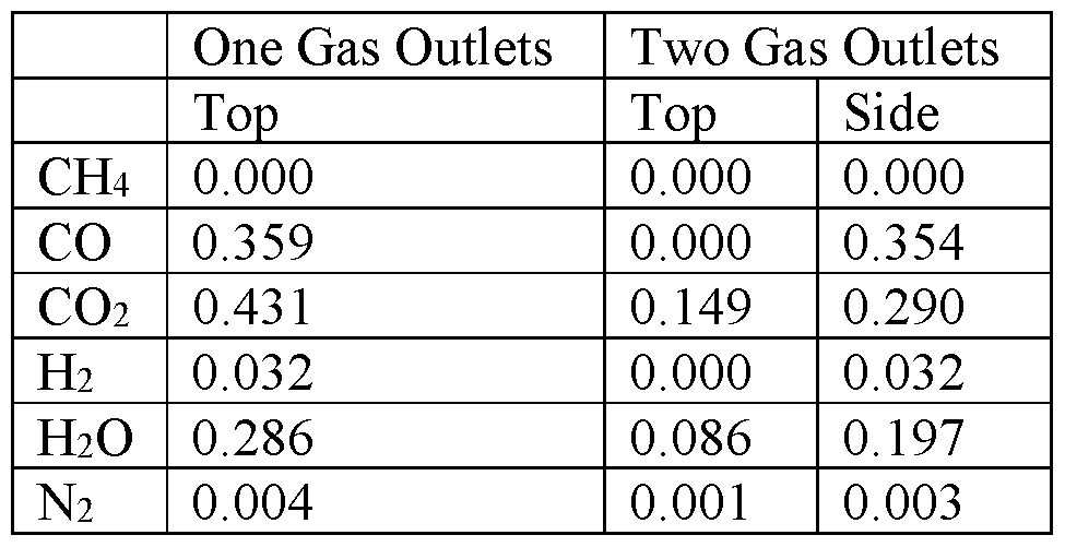
- Table 4 The performance of the two cases is summarized in Table 4. The molar flows of feedstock and products of this study are normalized based on 1 kmol/hr natural gas injection into the reducer.
- both systems operate with a tail gas/natural gas feedstock molar ratio of 6.9.
- the operating conditions of both systems are adjusted to maximize Fh yield while maintaining the solid temperature balance of the chemical looping system.
- the comparison between the two cases indicate that the staged injection option has significant advantages compared to the single port injection option in multiple aspects, including higher H2 yield, less steam consumption, and lower solid circulation rate.
- the staged injection case is able to generate 16.4% more H2 than the single port injection case using the same feedstock.
- the steam consumption of the staged injection case is 36.8% lower than the single stage injection case.
- the solid circulation rate of the staged injection case is 24.9% lower than the single stage system, which leads to significant reduction in reactor size.
- a reason for the various benefits of the staged injection case is the change in thermodynamics inside the reducer induced by the change in the locations of feedstock injection.
- the metal oxide particles are exposed to a more reducing environment at the bottom of the reducer compared to the single port injection mode.
- the more reducing environment at the reducer bottom enables the reduction of particles into a lower oxidation state, as indicated by the comparison between the solid conversion of the two cases.
- the single port injection case can reduce the particles to a maximum solid conversion of 34.1%
- the staged injection case can reduce the particles to a maximum solid conversion of 45.4%.
- Higher solid conversion means that more H2 can be produced from the oxidizer using less steam, as previously indicated in Table 4.
- a method for operating a reactor having a top and a bottom comprising: providing, in a first flow direction, metal particles to a solids inlet of the reactor, wherein the metal particles have at least two oxidation states; and wherein the metal particles enter the solids inlet at a first oxidation state; providing, in a second flow direction, an inlet gas stream to a gas inlet of the reactor, such that the first flow direction and the second flow direction are counter-current; providing a first gas outlet stream via a first gas outlet arranged proximate a top of the reactor, wherein at least 85% of carbon species in the first gas outlet stream is in the form of carbon dioxide (CO2); providing a second gas outlet stream via a second gas outlet positioned below the first gas outlet; and discharging metal particles via a solids outlet positioned proximate a bottom portion of the reactor, the metal particles being at a second oxidation state that is different from the first oxidation state, wherein the metal particles comprise less oxygen at the solids
- CO2 carbon
- Clause 2 The method according to clause 1, further comprising recycling the second gas outlet stream at a position in the reactor that is relatively higher than the second gas outlet.
- Clause 3 The method according to clause 1 or clause 2, further comprising: discharging metal particles via a second solids outlet arranged at a side of the reactor and above the bottom of the reactor, wherein the metal particles discharged at the solids outlet comprise less oxygen than the metal particles discharged at the second solids outlet.
- Clause 4 The method according to any one of clauses 1-3, the metal particles being discharged through the second solids outlet at a position that is relatively higher in the reactor than the second gas outlet.
- Clause 5 The method according to clause 4, further comprising recycling the metal particles discharged through the second solids outlet back through a second solids inlet positioned lower in the reactor than the second solids outlet.
- Clause 6 The method according to any one of clauses 1-5, further comprising providing the inlet gas stream in the first flow direction such that a portion of the inlet gas stream flows co- currently with the metal particles.
- Clause 7 The method according to clause 6, wherein the gas inlet of the reactor is positioned at a side of the reactor positioned below the top of the reactor.
- Clause 8 The method according to any one of clauses 1-7, wherein the gas inlet of the reactor is positioned at the bottom of the reactor.
- Clause 9 The method according to clause 8, further comprising providing a second gas inlet stream via a second gas inlet, the second gas inlet being positioned relatively higher in the reactor than the second gas outlet.
- Clause 10 The method according to clause 9, further comprising recycling a portion of the second gas outlet stream back through the second gas inlet.
- Clause 11 The method according to any one of clauses 1-10, wherein 60-75% of the inlet gas stream is provided in the first gas outlet stream.
- Clause 12 The method according to any one of clauses 1-11, wherein at least 95% of carbon species in the first gas outlet stream is carbon dioxide (CO2).
- Clause 13 The method according to any one of clauses 1-12, wherein the metal particles comprise iron ore.
- Clause 14 The method according to any one of clauses 1-13, wherein the inlet gas stream comprises carbon monoxide (CO) and hydrogen (Th).
- a method for operating a reactor having a top and a bottom comprising: providing, in a first flow direction, metal oxide particles to a solids inlet of the reactor, where the metal oxide particles have at least two oxidation states; and wherein the metal oxide particles enter the solids inlet at a first oxidation state; providing, in a second flow direction, a first inlet gas stream to a first gas inlet proximate the bottom of the reactor, such that the first flow direction and the second flow direction are counter-current, providing a second inlet gas stream in the second flow direction to a second gas inlet of the reactor, the second gas inlet positioned closer to a top of the reactor than the first gas inlet; providing a gas outlet stream via a gas outlet arranged near the top of the reactor, wherein the metal oxide particles below the second gas inlet comprise more oxygen than the metal oxide particles below the first gas inlet.
- At least 85% of carbon in the first gas outlet stream being in the form of carbon dioxide (CO2); and discharging metal particles via a solids outlet positioned proximate a bottom portion of the reactor, the metal particles being at a second oxidation state that is different from the first oxidation state.
- CO2 carbon dioxide
- Clause 16 The method according to clause 15, further comprising discharging metal oxide particles via a second solids outlet arranged at a side of the reactor and above the bottom of the reactor.
- Clause 17 The method according to clause 15 or clause 16, wherein the metal oxide particles are iron oxide particles; and wherein the second gas inlet stream comprises carbon dioxide (CO2), carbon monoxide (CO), and hydrogen (H2).
- a reactor in a chemical looping system comprising: a solids inlet arranged to provide metal oxide particles in a first flow direction, where the metal oxide particles have at least two oxidation states; and wherein the metal oxide particles enter the solids inlet at a first oxidation state; a first gas inlet arranged to provide an inlet gas stream in a second flow direction such that the first flow direction and the second flow direction are counter-current, the first gas inlet positioned near a bottom of the reactor; a second gas inlet arranged to provide a gas stream in the second flow direction, the second gas inlet positioned closer to a top of the reactor than the first gas inlet; a gas outlet arranged near the top of the reactor and configured to provide a gas outlet stream, wherein the metal oxide particles below the second gas inlet comprise more oxygen than the metal oxide particles below the first gas inlet.
- At least 85% of carbon in the first gas outlet stream being in the form of carbon dioxide (CO2); and a solids outlet positioned near the bottom of the reactor and configured to provide metal oxide particles at a second oxidation state that is different from the first oxidation state.
- CO2 carbon dioxide
- Clause 20 The reactor according to clause 18 or clause 19, wherein the second gas inlet stream comprises carbon dioxide (CO2), carbon monoxide (CO), and hydrogen (H2).
Landscapes
- Chemical & Material Sciences (AREA)
- Chemical Kinetics & Catalysis (AREA)
- Organic Chemistry (AREA)
- General Chemical & Material Sciences (AREA)
- Physics & Mathematics (AREA)
- Thermal Sciences (AREA)
- Carbon And Carbon Compounds (AREA)
- Medicines Containing Antibodies Or Antigens For Use As Internal Diagnostic Agents (AREA)
Abstract
Description


Claims
Priority Applications (5)
| Application Number | Priority Date | Filing Date | Title |
|---|---|---|---|
| AU2021301359A AU2021301359A1 (en) | 2020-06-29 | 2021-06-29 | Systems and methods for high reactant conversion through multiple reactant flow ratio staging |
| EP21832226.1A EP4164786A4 (en) | 2020-06-29 | 2021-06-29 | SYSTEMS AND METHODS FOR HIGHLY REACTANT CONVERSION BY STAGED ARRANGEMENT OF MULTIPLE REACTANT FLOW RATIO |
| CN202180045806.0A CN116096492A (en) | 2020-06-29 | 2021-06-29 | System and method for high reactant conversion by multiple reactant flow ratio fractionation |
| US18/003,457 US12605764B2 (en) | 2020-06-29 | 2021-06-29 | Systems and methods for high reactant conversion through multiple reactant flow ratio staging |
| CA3183537A CA3183537A1 (en) | 2020-06-29 | 2021-06-29 | Systems and methods for high reactant conversion through multiple reactant flow ratio staging |
Applications Claiming Priority (2)
| Application Number | Priority Date | Filing Date | Title |
|---|---|---|---|
| US202063045393P | 2020-06-29 | 2020-06-29 | |
| US63/045,393 | 2020-06-29 |
Publications (1)
| Publication Number | Publication Date |
|---|---|
| WO2022006112A1 true WO2022006112A1 (en) | 2022-01-06 |
Family
ID=79315558
Family Applications (1)
| Application Number | Title | Priority Date | Filing Date |
|---|---|---|---|
| PCT/US2021/039622 Ceased WO2022006112A1 (en) | 2020-06-29 | 2021-06-29 | Systems and methods for high reactant conversion through multiple reactant flow ratio staging |
Country Status (6)
| Country | Link |
|---|---|
| US (1) | US12605764B2 (en) |
| EP (1) | EP4164786A4 (en) |
| CN (1) | CN116096492A (en) |
| AU (1) | AU2021301359A1 (en) |
| CA (1) | CA3183537A1 (en) |
| WO (1) | WO2022006112A1 (en) |
Citations (4)
| Publication number | Priority date | Publication date | Assignee | Title |
|---|---|---|---|---|
| US4212452A (en) * | 1979-04-30 | 1980-07-15 | Jack Hsieh | Apparatus for the direct reduction of iron ore |
| US5545251A (en) * | 1993-08-07 | 1996-08-13 | MAN Gutehoffnungsh utte Aktiengesellschaft | Method of and device for directly reducing fine-particle ores and concentrates thereof |
| US5762681A (en) * | 1994-12-29 | 1998-06-09 | Pohang Iron & Steel Co., Ltd. | Fluidized bed type reduction apparatus for iron ores and method for reducing iron ores using the apparatus |
| US20050175533A1 (en) * | 2003-12-11 | 2005-08-11 | Thomas Theodore J. | Combustion looping using composite oxygen carriers |
Family Cites Families (294)
| Publication number | Priority date | Publication date | Assignee | Title |
|---|---|---|---|---|
| US1658939A (en) | 1928-02-14 | Chaeles e | ||
| US2899374A (en) | 1959-08-11 | Methods and apparatus for handling particulate solids | ||
| US971206A (en) | 1908-12-02 | 1910-09-27 | Corp Internationale Wasserstoff Ag | Process of producing hydrogen. |
| US1078686A (en) | 1910-07-16 | 1913-11-18 | Int Wasserstoff Ag | Process for the production of hydrogen. |
| US2198560A (en) | 1938-04-18 | 1940-04-23 | Kellogg M W Co | Method for the production of hydrogen |
| US2182747A (en) | 1938-04-18 | 1939-12-05 | Kellogg M W Co | Production of hydrogen by the high pressure iron process |
| US2449635A (en) | 1943-03-19 | 1948-09-21 | Standard Catalytic Co | Production of hydrogen |
| US2614067A (en) | 1948-07-02 | 1952-10-14 | Union Oil Co | Refining process and apparatus |
| US2635947A (en) | 1948-07-02 | 1953-04-21 | Union Oil Co | Hydrogen process |
| US2694622A (en) | 1948-07-02 | 1954-11-16 | Union Oil Co | Hydrocarbon refining apparatus |
| US2686819A (en) | 1949-09-01 | 1954-08-17 | Kellogg M W Co | Synthesis of methane |
| US2697686A (en) | 1951-04-26 | 1954-12-21 | Universal Oil Prod Co | Method for effecting the conversion of fluid reactant streams by contact with a moving bed of solid particles |
| US3031287A (en) | 1958-06-23 | 1962-04-24 | Homer E Benson | Process for manufacturing mixtures of hydrogen, carbon monoxide, and methane |
| US2979384A (en) | 1958-12-22 | 1961-04-11 | Parsons Co Ralph M | Process for production of hydrogen and sulfur |
| US3027238A (en) | 1959-12-07 | 1962-03-27 | Universal Oil Prod Co | Hydrogen manufacture |
| NL293037A (en) | 1962-05-23 | |||
| FR1043603A (en) | 1963-02-20 | 1953-11-10 | Jumper in elastic material usable in files | |
| US3338667A (en) | 1963-12-02 | 1967-08-29 | Johns Manville | Recovery of silica, iron oxide and magnesium carbonate from the treatment of serpentine with ammonium bisulfate |
| US3421869A (en) | 1964-06-01 | 1969-01-14 | Con Gas Service Corp | Method for the production of a mixture of hydrogen and steam |
| US3442613A (en) | 1965-10-22 | 1969-05-06 | Braun & Co C F | Hydrocarbon reforming for production of a synthesis gas from which ammonia can be prepared |
| GB1150906A (en) | 1966-07-27 | 1969-05-07 | Mullard Ltd | Improvement relating to Screened Ferrite Elements |
| US3573224A (en) | 1967-11-14 | 1971-03-30 | Chemical Construction Corp | Production of hydrogen-rich synthesis gas |
| US3494858A (en) | 1967-11-17 | 1970-02-10 | Exxon Research Engineering Co | Two-stage countercurrent catalyst regenerator |
| US3442619A (en) | 1968-03-27 | 1969-05-06 | Consolidation Coal Co | Production of hydrogen via the steam-iron process utilizing dual solids recycle |
| US3442620A (en) | 1968-04-18 | 1969-05-06 | Consolidation Coal Co | Production of hydrogen via the steam-iron process |
| US3619142A (en) | 1969-02-11 | 1971-11-09 | Consolidation Coal Co | Continuous steam-iron process |
| US3726966A (en) | 1970-10-06 | 1973-04-10 | Phillips Petroleum Co | Barium promoted iron oxide for use as a catalyst in steam-iron process for producing hydrogen |
| NO127185B (en) | 1971-10-08 | 1973-05-21 | Elkem Spigerverket As | |
| US3801661A (en) | 1972-07-11 | 1974-04-02 | Dow Chemical Co | Selective process for the continuous dyhydrogenation of nonaromatic hydrocarbons |
| JPS5111032B2 (en) | 1973-10-29 | 1976-04-08 | ||
| US4017270A (en) | 1974-01-31 | 1977-04-12 | Kamyr, Inc. | Coal gasification process with improved procedures for continuously feeding lump coal under pressure |
| US4334959A (en) | 1974-03-07 | 1982-06-15 | Occidental Petroleum Corporation | Mixing method and apparatus |
| CA1050736A (en) | 1974-05-24 | 1979-03-20 | Occidental Petroleum Corporation | Mixing of particulate materials |
| US4075079A (en) | 1976-06-09 | 1978-02-21 | Exxon Research & Engineering Co. | Process for the production of hydrocarbons from coal |
| US4057402A (en) | 1976-06-28 | 1977-11-08 | Institute Of Gas Technology | Coal pretreatment and gasification process |
| US4151124A (en) | 1977-12-16 | 1979-04-24 | Institute Of Gas Technology | Sorbent composition and process for preparing it |
| US4155832A (en) | 1977-12-23 | 1979-05-22 | The United States Of America As Represented By The United States Department Of Energy | Hydrogenation process for solid carbonaceous materials |
| US4160663A (en) * | 1978-02-21 | 1979-07-10 | Jack Hsieh | Method for the direct reduction of iron ore |
| US4375983A (en) | 1979-04-26 | 1983-03-08 | Hylsa, S.A. | Method of making sponge metal |
| US4272399A (en) | 1979-09-21 | 1981-06-09 | Monsanto Company | Conversion of carbon-containing materials to synthesis gas |
| US4343624A (en) | 1979-12-10 | 1982-08-10 | Caterpillar Tractor Co. | Rotating fluidized bed hydrogen production system |
| US4318711A (en) | 1979-12-28 | 1982-03-09 | Atlantic Richfield Company | Converting low BTU gas to high BTU gas |
| US4325833A (en) | 1980-06-27 | 1982-04-20 | Chevron Research Company | Three-stage catalyst regeneration |
| JPS5836034B2 (en) | 1980-12-22 | 1983-08-06 | 重質油対策技術研究組合 | Method for producing reduced iron through pyrolysis of heavy oil |
| CA1134596A (en) | 1981-07-06 | 1982-11-02 | Leo A. Behie | Process for producing hydrogen from hydrogen sulphide in a gas fluidized bed reactor |
| US4348487A (en) | 1981-11-02 | 1982-09-07 | Exxon Research And Engineering Co. | Production of methanol via catalytic coal gasification |
| US4404086A (en) | 1981-12-21 | 1983-09-13 | Standard Oil Company (Indiana) | Radial flow retorting process with trays and downcomers |
| NL190510C (en) | 1983-02-17 | 1994-04-05 | Hoogovens Groep Bv | Gas mixer. |
| US4778585A (en) | 1983-07-14 | 1988-10-18 | Research Foundation Of The City Univ. Of Ny | Two-stage pyrolysis of coal for producing liquid hydrocarbon fuels |
| US4594140A (en) | 1984-04-04 | 1986-06-10 | Cheng Shang I | Integrated coal liquefaction, gasification and electricity production process |
| FR2563118B1 (en) | 1984-04-20 | 1987-04-30 | Creusot Loire | PROCESS AND PLANT FOR TREATING FLUIDIZED BED MATERIAL |
| US4861165A (en) | 1986-08-20 | 1989-08-29 | Beloit Corporation | Method of and means for hydrodynamic mixing |
| US4869207A (en) | 1987-07-13 | 1989-09-26 | A. Ahlstrom Corporation | Circulating fluidized bed reactor |
| FR2619023B1 (en) | 1987-08-07 | 1991-04-12 | Lamort E & M | PRESSURE MIXER INJECTOR |
| DE3727119A1 (en) | 1987-08-14 | 1989-02-23 | Didier Werke Ag | METHOD FOR PRODUCING CATALYSTS FOR REDUCING NITROGEN OXIDES FROM EXHAUST GASES OR FOR CHEMICAL AIR PURIFYING METHODS AND CATALYSTS MANUFACTURED BY THE METHOD |
| GB8726804D0 (en) | 1987-11-16 | 1987-12-23 | Boc Group Plc | Separation of gas mixtures including hydrogen |
| US5130106A (en) | 1988-12-28 | 1992-07-14 | Uop | Moving bed radial flow reactor for high gas flow |
| US4957523A (en) | 1989-01-27 | 1990-09-18 | Pacific Consolidated Industries | High speed pressure swing adsorption liquid oxygen/liquid nitrogen generating plant |
| WO1990013773A1 (en) | 1989-05-01 | 1990-11-15 | Ronald Stanley Tabery | Fluidized bed device for combustion of low-melting fuels |
| US5916529A (en) | 1989-07-19 | 1999-06-29 | Chevron U.S.A. Inc | Multistage moving-bed hydroprocessing reactor with separate catalyst addition and withdrawal systems for each stage, and method for hydroprocessing a hydrocarbon feed stream |
| JPH0368898A (en) | 1989-08-08 | 1991-03-25 | Nippon Nuclear Fuel Dev Co Ltd | Method of manufacturing nuclear fuel pellet |
| US4902586A (en) | 1989-08-28 | 1990-02-20 | International Fuel Cells Corporation | Once through molten carbonate fuel cell system |
| US5078787A (en) | 1990-06-01 | 1992-01-07 | Hylsa S.A. De C.V. | Method and apparatus for the production of hot direct reduced iron |
| HU9201539D0 (en) | 1990-09-11 | 1992-08-28 | Kortec Ag | Method and device for gasifying gasifiable materials and/or transforming gas as well as heat exchanger of high temperature for executing said method |
| US5578498A (en) | 1991-05-22 | 1996-11-26 | Behringwerke Ag | Metal chelate containing compositions for use in chemiluminescent assays |
| US5365560A (en) | 1991-07-29 | 1994-11-15 | General Electric Company | Method and apparatus for acquiring a uniform distribution of radon data sufficiently dense to constitute a complete set for exact image reconstruction of an object irradiated by a cone beam source |
| JP3315719B2 (en) | 1992-06-03 | 2002-08-19 | 東京電力株式会社 | Chemical loop combustion power plant system |
| NZ248813A (en) | 1992-11-25 | 1995-06-27 | Eastman Kodak Co | Polymeric grinding media used in grinding pharmaceutical substances |
| US5827496A (en) | 1992-12-11 | 1998-10-27 | Energy And Environmental Research Corp. | Methods and systems for heat transfer by unmixed combustion |
| US5509362A (en) | 1992-12-11 | 1996-04-23 | Energy And Environmental Research Corporation | Method and apparatus for unmixed combustion as an alternative to fire |
| US5630368A (en) | 1993-05-24 | 1997-05-20 | The University Of Tennessee Research Corporation | Coal feed and injection system for a coal-fired firetube boiler |
| US5584615A (en) | 1993-12-27 | 1996-12-17 | Uop | Pneumatic particulate transport with gravity assisted flow |
| US5456807A (en) | 1994-03-09 | 1995-10-10 | Gas Research Institute | Method and apparatus for treating nitrogen oxide-containing gas streams using a combined electrochemical-sorbent approach |
| AT405187B (en) * | 1994-12-01 | 1999-06-25 | Voest Alpine Ind Anlagen | METHOD FOR THE PRODUCTION OF IRON SPONGE AND SYSTEM FOR IMPLEMENTING THE METHOD |
| KR100249936B1 (en) | 1995-01-20 | 2000-03-15 | 제이. 에이치. 블롬 | Method for desulfurising gas stream and absorber suitable for this method |
| US5529599A (en) | 1995-01-20 | 1996-06-25 | Calderon; Albert | Method for co-producing fuel and iron |
| US5891415A (en) | 1995-05-17 | 1999-04-06 | Azerbaidzhanskaya Gosudarstvennaya Neftianaya Academiya | Process for selective oxidation of hydrogen sulfide to elemental sulfur |
| DE19546476A1 (en) | 1995-12-13 | 1997-06-19 | Daimler Benz Ag | Catalyst, process for its manufacture and use thereof |
| DE19606657C1 (en) | 1996-02-23 | 1997-07-10 | Basf Ag | Process and device for cleaning gases |
| JPH09272815A (en) | 1996-04-02 | 1997-10-21 | Merck Japan Kk | Metal oxide composite fine particles and method for producing the same |
| TW406055B (en) | 1996-04-08 | 2000-09-21 | Air Prod & Chem | Integrated steam methane reforming process for producing carbon monoxide and hydrogen |
| US5858210A (en) | 1996-05-20 | 1999-01-12 | Uop Llc | Method for regulating particle transfer rates |
| US6007699A (en) | 1996-08-21 | 1999-12-28 | Energy And Environmental Research Corporation | Autothermal methods and systems for fuels conversion |
| JP3094093B2 (en) | 1997-03-11 | 2000-10-03 | 科学技術庁無機材質研究所長 | Method for immobilizing CO2 with alkaline earth silicate |
| DE19724286A1 (en) | 1997-06-09 | 1998-12-10 | Linde Ag | Process for removing nitrogen oxides from gases |
| US6025403A (en) | 1997-07-07 | 2000-02-15 | Mobil Oil Corporation | Process for heat integration of an autothermal reformer and cogeneration power plant |
| CN1502546A (en) | 1997-10-07 | 2004-06-09 | JFE�عɹ�˾ | Catalyst for producing hydrogen or synthesis gas and method for producing hydrogen or synthesis gas |
| WO2000022690A1 (en) | 1998-10-14 | 2000-04-20 | Northwest Power Systems, Llc | Fuel processing system |
| US6187465B1 (en) | 1997-11-07 | 2001-02-13 | Terry R. Galloway | Process and system for converting carbonaceous feedstocks into energy without greenhouse gas emissions |
| US5958222A (en) | 1997-11-17 | 1999-09-28 | Uop Llc | Standpipe distributor for short time contact of hydrocarbon compounds with particles |
| US6348278B1 (en) | 1998-06-09 | 2002-02-19 | Mobil Oil Corporation | Method and system for supplying hydrogen for use in fuel cells |
| US6334895B1 (en) | 1998-07-20 | 2002-01-01 | The University Of Wyoming Research Corporation | System for producing manufactured materials from coal combustion ash |
| GB9819645D0 (en) | 1998-09-10 | 1998-11-04 | Bp Chem Int Ltd | Process |
| US6258330B1 (en) | 1998-11-10 | 2001-07-10 | International Fuel Cells, Llc | Inhibition of carbon deposition on fuel gas steam reformer walls |
| US6534437B2 (en) | 1999-01-15 | 2003-03-18 | Akzo Nobel N.V. | Process for preparing a mixed metal catalyst composition |
| US6143203A (en) | 1999-04-13 | 2000-11-07 | The Boc Group, Inc. | Hydrocarbon partial oxidation process |
| AU4835800A (en) | 1999-05-07 | 2000-11-21 | Rentech, Inc. | Convertible methanol/fischer-tropsch plant and method |
| US6969506B2 (en) | 1999-08-17 | 2005-11-29 | Battelle Memorial Institute | Methods of conducting simultaneous exothermic and endothermic reactions |
| FI107758B (en) | 1999-11-10 | 2001-09-28 | Foster Wheeler Energia Oy | Reactor with circulating fluidized bed |
| US6790430B1 (en) | 1999-12-09 | 2004-09-14 | The Regents Of The University Of California | Hydrogen production from carbonaceous material |
| CA2340822C (en) | 2000-03-17 | 2010-08-03 | Snamprogetti S.P.A. | Process for the production of hydrogen |
| EP1136467A1 (en) | 2000-03-24 | 2001-09-26 | Aventis Animal Nutrition S.A. | Catalytic conversion of alkanes to alkenes |
| JP2001299744A (en) | 2000-04-18 | 2001-10-30 | Hitachi Medical Corp | Medical radiotomographic instrument |
| NZ535558A (en) | 2000-04-24 | 2006-11-30 | Shell Int Research | In situ recovery from a hydrocarbon containing formation |
| AU2001281329A1 (en) | 2000-07-25 | 2002-02-05 | Apollo Energy Systems, Incorporated | Ammonia cracker for production of hydrogen |
| US7247279B2 (en) | 2000-08-01 | 2007-07-24 | Enviroscrub Technologies Corporation | System for removal of pollutants from a gas stream |
| US6506351B1 (en) | 2000-08-11 | 2003-01-14 | The Boc Group, Inc. | Removal of nitrogen oxides from gas streams |
| US6509000B1 (en) | 2000-08-31 | 2003-01-21 | Council Of Scientific And Industrial Research | Low temperature process for the production of hydrogen |
| DE10047642A1 (en) | 2000-09-26 | 2002-04-11 | Basf Ag | Process for the dehydrogenation of hydrocarbons |
| US6444712B1 (en) | 2000-09-28 | 2002-09-03 | Exxonmobil Chemical Patents, Inc. | Methanol, olefin, and hydrocarbon synthesis process |
| WO2002058557A2 (en) | 2000-10-24 | 2002-08-01 | The Johns Hopkins University | Method and apparatus for multiple-projection, dual-energy x-ray absorptiometry scanning |
| US6412559B1 (en) | 2000-11-24 | 2002-07-02 | Alberta Research Council Inc. | Process for recovering methane and/or sequestering fluids |
| DE10063862A1 (en) | 2000-12-21 | 2002-07-11 | Solarworld Ag | Process for the production of high-purity, granular silicon |
| AU2002335499A1 (en) | 2001-03-02 | 2002-09-19 | Mesosystems Technology, Inc. | Ammonia-based hydrogen generation apparatus and method for using same |
| US6663681B2 (en) | 2001-03-06 | 2003-12-16 | Alchemix Corporation | Method for the production of hydrogen and applications thereof |
| US6685754B2 (en) | 2001-03-06 | 2004-02-03 | Alchemix Corporation | Method for the production of hydrogen-containing gaseous mixtures |
| US6682714B2 (en) | 2001-03-06 | 2004-01-27 | Alchemix Corporation | Method for the production of hydrogen gas |
| ATE318792T1 (en) | 2001-04-20 | 2006-03-15 | Shell Int Research | METHOD FOR CARBONIZING MINERALS USING CARBON DIOXIDE |
| US20020179887A1 (en) | 2001-05-01 | 2002-12-05 | Yongxian Zeng | Supported perovskite-type oxides and methods for preparation thereof |
| EP1262235A3 (en) | 2001-05-23 | 2003-04-16 | Rohm And Haas Company | Mixed-metal oxide catalysts containing molybdenum and vanadium and processes for preparing the same |
| JP4092090B2 (en) | 2001-06-26 | 2008-05-28 | 株式会社日本触媒 | Solid particle packed reactor and catalytic gas phase oxidation method using the reactor |
| US6568206B2 (en) | 2001-07-18 | 2003-05-27 | Air Products And Chemicals, Inc. | Cryogenic hydrogen and carbon monoxide production with membrane permeate expander |
| US6494153B1 (en) | 2001-07-31 | 2002-12-17 | General Electric Co. | Unmixed combustion of coal with sulfur recycle |
| US6669917B2 (en) | 2001-07-31 | 2003-12-30 | General Electric Co. | Process for converting coal into fuel cell quality hydrogen and sequestration-ready carbon dioxide |
| US6834623B2 (en) | 2001-08-07 | 2004-12-28 | Christopher T. Cheng | Portable hydrogen generation using metal emulsions |
| US6667022B2 (en) | 2001-08-14 | 2003-12-23 | General Electric Co. | Process for separating synthesis gas into fuel cell quality hydrogen and sequestration ready carbon dioxide |
| US20040244289A1 (en) | 2001-09-28 | 2004-12-09 | Fumiaki Morozumi | Process for reforming inflammable gas, apparatus for reforming inflammable gas and gasification apparatus |
| US6607704B2 (en) | 2001-10-18 | 2003-08-19 | Ford Global Technologies, Llc | Sulfur tolerant lean NOx trap |
| US6797253B2 (en) | 2001-11-26 | 2004-09-28 | General Electric Co. | Conversion of static sour natural gas to fuels and chemicals |
| FR2833005B1 (en) | 2001-11-30 | 2004-01-23 | Atofina | PROCESS FOR MANUFACTURING ACRYLIC ACID FROM PROPANE AND IN THE ABSENCE OF MOLECULAR OXYGEN |
| US6703343B2 (en) | 2001-12-18 | 2004-03-09 | Caterpillar Inc | Method of preparing doped oxide catalysts for lean NOx exhaust |
| US20030119658A1 (en) | 2001-12-21 | 2003-06-26 | Conocophillips Company | Recovery of rhenium from a spent catalyst via sublimation |
| DE10202127A1 (en) | 2002-01-22 | 2003-07-31 | Kataleuna Gmbh Catalysts | Spherical, highly active metal supported catalysts |
| US6747066B2 (en) | 2002-01-31 | 2004-06-08 | Conocophillips Company | Selective removal of oxygen from syngas |
| US20080031809A1 (en) | 2006-07-18 | 2008-02-07 | Norbeck Joseph M | Controlling the synthesis gas composition of a steam methane reformer |
| US20030162846A1 (en) | 2002-02-25 | 2003-08-28 | Wang Shoou-L | Process and apparatus for the production of synthesis gas |
| EP1487740A1 (en) | 2002-03-13 | 2004-12-22 | Conocophillips Company | Controlled-pore catalyst structures and process for producing synthesis gas |
| US7244399B2 (en) | 2002-04-26 | 2007-07-17 | Foster Wheeler Energia Oy | Grid construction for a fluidized bed reactor |
| TWI225426B (en) | 2002-05-01 | 2004-12-21 | Rohm & Haas | Supported mixed metal oxide catalyst |
| CN1662440A (en) | 2002-06-26 | 2005-08-31 | 打矢恒温器株式会社 | Method for producing hydrogen and apparatus for supplying hydrogen |
| EP1375827A1 (en) | 2002-06-28 | 2004-01-02 | Siemens Aktiengesellschaft | Steam power plant |
| AU2003301247A1 (en) | 2002-10-16 | 2004-05-04 | Conocophillips Company | Fischer-tropsch processes and catalysts made from a material comprising boehmite |
| AU2003286455A1 (en) | 2002-10-17 | 2004-05-04 | Mykrolis Corporation | Method for purifying carbon dioxide |
| US20040126293A1 (en) | 2002-10-23 | 2004-07-01 | Geerlings Jacobus Johannes Cornelis | Process for removal of carbon dioxide from flue gases |
| CA2448715C (en) | 2002-11-11 | 2011-07-05 | Nippon Telegraph And Telephone Corporation | Fuel cell power generating system with two fuel cells of different types and method of controlling the same |
| CA2504206A1 (en) | 2002-11-11 | 2004-05-27 | Conocophillips Company | Stabilized alumina supports, catalysts made therefrom, and their use in partial oxidation |
| US7945021B2 (en) | 2002-12-18 | 2011-05-17 | Varian Medical Systems, Inc. | Multi-mode cone beam CT radiotherapy simulator and treatment machine with a flat panel imager |
| ITMI20030192A1 (en) | 2003-02-05 | 2004-08-06 | Eni Spa | CATALYTIC SYSTEM AND PRODUCTION PROCESS |
| US7067456B2 (en) | 2003-02-06 | 2006-06-27 | The Ohio State University | Sorbent for separation of carbon dioxide (CO2) from gas mixtures |
| WO2004076017A2 (en) | 2003-02-26 | 2004-09-10 | Questair Technologies Inc. | Hydrogen recycle for high temperature fuel cells |
| US20040213705A1 (en) | 2003-04-23 | 2004-10-28 | Blencoe James G. | Carbonation of metal silicates for long-term CO2 sequestration |
| US7604787B2 (en) | 2003-05-02 | 2009-10-20 | The Penn State Research Foundation | Process for sequestering carbon dioxide and sulfur dioxide |
| US7075532B2 (en) | 2003-05-23 | 2006-07-11 | International Business Machines Corporation | Robust tetrahedralization and triangulation method with applications in VLSI layout design and manufacturability |
| US7255840B2 (en) | 2003-06-26 | 2007-08-14 | Praxair Technology, Inc. | Autothermal reactor and method for production of synthesis gas |
| TW200519072A (en) | 2003-08-21 | 2005-06-16 | Pearson Technologies Inc | Process and apparatus for the production of useful products from carbonaceous feedstock |
| AU2003256141A1 (en) | 2003-08-22 | 2005-03-10 | Instituto Mexicano Del Petroleo | Method of viewing multiphase flows using electrical capacitance tomography |
| DE10361286B4 (en) | 2003-12-24 | 2013-09-19 | Daimler Ag | Process for the regeneration of a nitrogen oxide storage catalyst |
| US20070157517A1 (en) | 2004-02-06 | 2007-07-12 | David Tsay | Single stage membrane reactor for high purity hydrogen production |
| ITMI20040555A1 (en) | 2004-03-23 | 2004-06-23 | Eni Spa | PROCEDURE FOR THE PRODUCTION OF HYDROGEN AND THE CO-PRODUCTION OF CARBON DIOXIDE |
| US20050274648A1 (en) | 2004-04-21 | 2005-12-15 | Goldstein Stuart S | Method for revamping fixed-bed catalytic reformers |
| BRPI0511863A (en) | 2004-06-08 | 2008-01-15 | Cummins Inc | method for modifying the trigger level for adsorbent regeneration |
| US7547419B2 (en) | 2004-06-16 | 2009-06-16 | United Technologies Corporation | Two phase injector for fluidized bed reactor |
| US20060021308A1 (en) | 2004-07-29 | 2006-02-02 | Merkel Gregory A | Mullite-aluminum titanate body and method for making same |
| US20060042565A1 (en) | 2004-08-26 | 2006-03-02 | Eaton Corporation | Integrated fuel injection system for on-board fuel reformer |
| US7223714B2 (en) | 2004-11-04 | 2007-05-29 | Exxonmobil Chemical Patents Inc. | Method of transferring catalyst in a reaction system |
| KR100655133B1 (en) | 2005-03-02 | 2006-12-08 | 아주대학교산학협력단 | Metal Oxide Catalyst for Nitric Oxide Removal |
| EP2279785A3 (en) | 2005-03-29 | 2011-09-21 | Yanmar Co. Ltd. | Exhaust gas purifier |
| US20110289845A1 (en) | 2005-04-12 | 2011-12-01 | Ze-Gen, Inc. | Method for controlling syngas production in a system with multiple feed materials using a molten metal bath |
| US7429373B2 (en) | 2005-06-24 | 2008-09-30 | Air Products And Chemicals, Inc. | Process for autothermal generation of hydrogen |
| FR2889248B1 (en) | 2005-07-29 | 2007-09-07 | Inst Francais Du Petrole | NOVEL OXYDO-REDUCTIVE ACTIVE MASS FOR A LOOP OXYDO-REDUCTION PROCESS |
| US7842635B2 (en) | 2006-01-06 | 2010-11-30 | Headwaters Technology Innovation, Llc | Hydrocarbon-soluble, bimetallic catalyst precursors and methods for making same |
| CN101389734A (en) | 2006-01-12 | 2009-03-18 | 俄亥俄州立大学 | System and method for converting fuel |
| CN102390979A (en) | 2006-01-12 | 2012-03-28 | 俄亥俄州立大学 | Systems and methods of converting fuel |
| DE102006017614A1 (en) | 2006-04-12 | 2007-10-18 | J. Eberspächer GmbH & Co. KG | Fuel cell system and associated operating method |
| UA97804C2 (en) | 2006-04-24 | 2012-03-26 | Юниверсити Оф Зе Витватерсренд, Йоханнесбург | Method for producing of hydrocarbons |
| NZ573217A (en) | 2006-05-05 | 2011-11-25 | Plascoenergy Ip Holdings S L Bilbao Schaffhausen Branch | A facility for conversion of carbonaceous feedstock into a reformulated syngas containing CO and H2 |
| WO2007134075A2 (en) | 2006-05-08 | 2007-11-22 | Alchemix Corporation | Method for the gasification of hydrocarbon feedstocks |
| EP2195401A2 (en) | 2006-08-04 | 2010-06-16 | Ernest R. Zabolotny | Gasification process |
| US7824574B2 (en) | 2006-09-21 | 2010-11-02 | Eltron Research & Development | Cyclic catalytic upgrading of chemical species using metal oxide materials |
| CA2860684C (en) | 2006-09-25 | 2015-12-01 | The Ohio State University | High purity, high pressure hydrogen production with in-situ co2 and sulfur capture in a single stage reactor |
| US20080134666A1 (en) | 2006-12-11 | 2008-06-12 | Parag Prakash Kulkarni | Systems and Methods Using an Unmixed Fuel Processor |
| WO2008071215A1 (en) | 2006-12-14 | 2008-06-19 | Horst Grochowski | Method and device for scrubbing effluent gases from a sintering process for ores or other metal-containing materials in metal production |
| US7902416B2 (en) | 2006-12-28 | 2011-03-08 | Uop Llc | Fluidized bed reactor with back-mixing for dehydrogenation of light paraffins |
| WO2008082312A1 (en) | 2007-01-05 | 2008-07-10 | Sinvent As | Hydrogen production |
| NO328522B1 (en) | 2007-03-19 | 2010-03-08 | Statoil Asa | Hydrogen production process, hydrogen production plant, a water gas exchange reactor and a process for producing hydrogen from syngas. |
| US7840053B2 (en) | 2007-04-05 | 2010-11-23 | Liao Hstau Y | System and methods for tomography image reconstruction |
| CA2693117A1 (en) | 2007-06-14 | 2008-12-24 | Kansas State University Research Foundation | Fluidized bed precipitator |
| DE102007031635A1 (en) | 2007-07-06 | 2009-01-15 | Evonik Degussa Gmbh | Process for the preparation of metal oxide granules |
| KR100896455B1 (en) | 2007-07-09 | 2009-05-14 | 한국에너지기술연구원 | Pressure swing adsorption apparatus and method for hydrogen purification using the same |
| CN101730658A (en) | 2007-07-09 | 2010-06-09 | 雷奇燃料公司 | Be used to produce the method and apparatus of synthetic gas |
| US8926717B2 (en) | 2007-07-27 | 2015-01-06 | The Trustees Of Columbia University In The City Of New York | Methods and systems for producing synthetic fuel |
| US20090042070A1 (en) | 2007-08-08 | 2009-02-12 | The University Corporation, Inc. At California State University, Northridge | Barometric thermal trap and collection apparatus and method thereof for combining multiple exhaust streams into one |
| WO2009023515A2 (en) | 2007-08-09 | 2009-02-19 | Eli Lilly And Company | Reactors and methods for processing reactants therein |
| AT505526B1 (en) | 2007-08-14 | 2010-09-15 | Univ Wien Tech | FLUID BED REACTOR SYSTEM |
| FR2923732B1 (en) | 2007-11-16 | 2011-03-04 | Nicolas Ugolin | METHOD USING PLASMA-COUPLED SOLAR THERMAL ENERGY TO PRODUCE LIQUID FUEL AND DIHYDROGEN FROM BIOMASS OR FOSSIL CHARCOAL (P-SL AND P-SH PROCESS) |
| FR2924035B1 (en) | 2007-11-23 | 2010-09-03 | Sebatien Roux | FORMULATION OF OXIDES, ITS OBTAINING AND ITS USE AS OXYGEN CARRIER IN A PROCESS FOR OXIDATION AND / OR DEOXIDATION OF A GASEOUS FLOW |
| US7880481B2 (en) | 2007-12-19 | 2011-02-01 | Infineon Technologies Ag | Capacitive sensor and measurement system |
| US9122260B2 (en) | 2008-03-03 | 2015-09-01 | Alstom Technology Ltd | Integrated controls design optimization |
| TWI461522B (en) | 2008-03-05 | 2014-11-21 | Thyssenkrupp Uhde Gmbh | Continuous fuel supply system for a coal gasification reactor |
| WO2009132031A2 (en) | 2008-04-21 | 2009-10-29 | Swapsol Corp. | Hydrogen sulfide conversion to hydrogen |
| FR2930733B1 (en) | 2008-04-30 | 2014-04-11 | Inst Francais Du Petrole | ACTIVE OXYDO-REDUCTION MASS AND CHEMICAL LOOP COMBUSTION METHOD |
| CN102076829B (en) | 2008-06-27 | 2013-08-28 | 格雷特波因特能源公司 | Four-train catalytic gasification systems |
| IT1393168B1 (en) | 2008-09-08 | 2012-04-11 | Senneca | PLANT AND PROCESS FOR "LOOPING" TYPE COMBUSTION OF CARBON SOLIDS |
| CN102159314B (en) | 2008-09-17 | 2016-08-03 | 株式会社日本触媒 | Ammonia decomposition catalyzer and preparation method thereof and ammonia treatment method |
| CN102159683B (en) | 2008-09-19 | 2014-10-01 | 格雷特波因特能源公司 | Processes for gasification of carbonaceous feedstock |
| CN105132025B (en) * | 2008-09-26 | 2018-02-06 | 俄亥俄州立大学 | Carbon-containing fuel is converted into carbon-free energy carrier |
| FR2937119B1 (en) | 2008-10-15 | 2010-12-17 | Air Liquide | METHOD FOR GENERATING ENERGY AND CAPTURING CO 2 |
| WO2010055861A1 (en) | 2008-11-14 | 2010-05-20 | ジェイパワー・エンテック株式会社 | Lock hopper |
| WO2010063923A2 (en) | 2008-12-02 | 2010-06-10 | Jean-Xavier Morin | Facility having thermochemical cycle for reactive fuel |
| US20100187159A1 (en) | 2009-01-28 | 2010-07-29 | Christopher Naunheimer | Moving Bed Hydrocarbon Conversion Process |
| CA2881239C (en) | 2009-01-21 | 2017-02-28 | Res Usa, Llc | System and method for dual fluidized bed gasification |
| JP2010167366A (en) | 2009-01-22 | 2010-08-05 | Ngk Insulators Ltd | Honeycomb catalytic article |
| FR2941689B1 (en) | 2009-01-30 | 2011-02-18 | Inst Francais Du Petrole | INTEGRATED OXIDATION, REDUCTION AND GASIFICATION PROCESS FOR THE PRODUCTION OF CHEMICAL LOOP SYNTHESIS GAS |
| US8057734B2 (en) * | 2009-02-24 | 2011-11-15 | Praxair Technology, Inc. | Producing metal and carbon dioxide with hydrogen recycle |
| GB0905222D0 (en) | 2009-03-26 | 2009-05-13 | Johnson Matthey Plc | Method for producing a supported metal nitrate |
| JP2012523420A (en) | 2009-04-10 | 2012-10-04 | ユニバーシティ オブ サザン カリフォルニア | Making coal an environmentally carbon-neutral fuel and renewable carbon source |
| US20100275514A1 (en) | 2009-04-14 | 2010-11-04 | Packer Engineering, Inc. | Biomass gasification/pyrolysis system and process |
| FR2945034B1 (en) | 2009-04-29 | 2012-06-08 | Inst Francais Du Petrole | INTEGRATED METHOD OF GENERATING ENERGY AND / OR SYNTHESIS GAS BY IN SITU OXYGEN PRODUCTION, CHEMICAL LOOP COMBUSTION AND GASIFICATION |
| US8500868B2 (en) | 2009-05-01 | 2013-08-06 | Massachusetts Institute Of Technology | Systems and methods for the separation of carbon dioxide and water |
| US8202349B2 (en) | 2009-06-30 | 2012-06-19 | General Electric Company | Method and apparatus for removal of carbon dioxide from pre-combustion syngas |
| WO2011002793A1 (en) | 2009-06-30 | 2011-01-06 | The University Of Connecticut | Multiple excitation capacitance polling for enhanced electronic capacitance tomography |
| WO2011006059A2 (en) | 2009-07-10 | 2011-01-13 | Southern Company | Carbon dioxide absorber and regeneration assemblies useful for power plant flue gas |
| US8394240B2 (en) | 2009-07-14 | 2013-03-12 | C2O Technologies, Llc | Process for treating bituminous coal by removing volatile components |
| FR2948177B1 (en) | 2009-07-16 | 2011-08-05 | Inst Francais Du Petrole | CHEMICAL LOOP COMBUSTION PROCESS WITH INDEPENDENT CONTROL OF SOLIDS CIRCULATION |
| WO2011022501A2 (en) | 2009-08-18 | 2011-02-24 | Van Dyke, Marc | Method and system for producing syngas |
| AU2010292310B2 (en) | 2009-09-08 | 2017-01-12 | The Ohio State University Research Foundation | Synthetic fuels and chemicals production with in-situ CO2 capture |
| CN102695670B (en) | 2009-09-08 | 2016-02-24 | 俄亥俄州立大学研究基金会 | Integration of reforming/water splitting with integrated carbon capture and electrochemical systems for power generation |
| US9873840B2 (en) | 2009-09-18 | 2018-01-23 | Wormser Energy Solutions, Inc. | Integrated gasification combined cycle plant with char preparation system |
| KR101029680B1 (en) | 2009-10-26 | 2011-04-15 | 상명대학교 산학협력단 | Storage and Decomposition of Dilute Nitrogen Oxides Using Mixed Metal Oxide Catalysts |
| US20110094226A1 (en) | 2009-10-28 | 2011-04-28 | Mchugh Lawrence F | Process and apparatus for high energy efficiency chemical looping combustion |
| US8356992B2 (en) | 2009-11-30 | 2013-01-22 | Chevron U.S.A. Inc. | Method and system for capturing carbon dioxide in an oxyfiring process where oxygen is supplied by regenerable metal oxide sorbents |
| US8961629B2 (en) | 2009-12-21 | 2015-02-24 | Southern Company Services, Inc. | Apparatus, components and operating methods for circulating fluidized bed transport gasifiers and reactors |
| US8761943B2 (en) | 2010-01-29 | 2014-06-24 | Alstom Technology Ltd | Control and optimization system and method for chemical looping processes |
| GB2477322B (en) | 2010-02-01 | 2015-10-21 | Gas Recovery & Recycle Ltd | Inert gas recovery system |
| DE102010028816A1 (en) | 2010-05-10 | 2011-11-10 | Highterm Research Gmbh | Fluidized bed reactor useful for producing product gas from carbon-containing input materials via allothermal gasification comprises combustion chamber with first fluidized bed, reformer reactor with second fluidized bed and feeding device |
| US8524159B2 (en) | 2010-05-28 | 2013-09-03 | Exxonmobil Chemical Patents Inc. | Reactor with reactor head and integrated valve |
| FR2960940B1 (en) | 2010-06-02 | 2015-08-07 | Inst Francais Du Petrole | CHEMICAL LOOP COMBUSTION PROCESS WITH A REACTION ZONE INTEGRATING A GAS-SOLID SEPARATION AREA AND INSTALLATION USING SUCH A METHOD |
| FR2960869B1 (en) | 2010-06-02 | 2014-08-08 | Inst Francais Du Petrole | PROCESS AND PLANT FOR PRODUCING OXYGEN BY FLUIDIZED BED CHEMICAL LOOP |
| AT509586B8 (en) | 2010-06-11 | 2011-12-15 | Univ Wien Tech | IMPROVED SWITCH LAYER REACTOR SYSTEM |
| US20130125462A1 (en) | 2010-08-02 | 2013-05-23 | Horst Greiner | Chemical looping system |
| US8508238B2 (en) | 2010-08-12 | 2013-08-13 | General Electric Company | System and method for performing electrical impedance tomography |
| CA2754948A1 (en) | 2010-10-13 | 2012-04-13 | Song Sit | Chemical looping combustion |
| FR2966160B1 (en) | 2010-10-14 | 2013-11-15 | IFP Energies Nouvelles | CATALYTIC CRACKING METHOD FOR PROCESSING LOW CARBON CONRADSON LOADS COMPRISING THE RECYCLING OF A CUTTING CUTTING ACCORDING TO A NEW TECHNOLOGY |
| EP2450420A1 (en) | 2010-11-08 | 2012-05-09 | Shell Internationale Research Maatschappij B.V. | Multi stage process for producing hydrocarbons from syngas |
| EP2637777A1 (en) | 2010-11-08 | 2013-09-18 | The Ohio State University | Circulating fluidized bed with moving bed downcomers and gas sealing between reactors |
| KR20120064030A (en) | 2010-12-08 | 2012-06-18 | 에스케이이노베이션 주식회사 | Carbon dioxide free gasification |
| EP2514516A1 (en) | 2011-04-21 | 2012-10-24 | Nederlandse Organisatie voor toegepast -natuurwetenschappelijk onderzoek TNO | Fixed bed filling composition |
| EP2515038A1 (en) | 2011-04-21 | 2012-10-24 | Nederlandse Organisatie voor toegepast -natuurwetenschappelijk onderzoek TNO | Fixed bed chemical looping combustion |
| CN103648969B (en) | 2011-05-06 | 2017-09-12 | 代表Mt创新中心的斯塔米卡邦有限公司 | Zero-emission sulfur recovery method for simultaneous hydrogen production |
| WO2012155054A1 (en) | 2011-05-11 | 2012-11-15 | The Ohio State University | Systems for converting fuel |
| CN103635673B (en) | 2011-05-11 | 2016-05-04 | 俄亥俄州国家创新基金会 | oxygen carrying material |
| FR2980258B1 (en) * | 2011-09-20 | 2017-12-29 | Ifp Energies Now | CHEMICAL LOOP COMBUSTION PROCESS WITH REMOVAL OF ASHES AND FINES IN THE REDUCTION AREA AND INSTALLATION USING SUCH A METHOD |
| US8562928B2 (en) | 2011-09-21 | 2013-10-22 | Shell Oil Company | Process for producing hydrogen, sulfur and sulfur dioxide from hydrogen sulfide-containing gas streams |
| US9017627B2 (en) | 2011-09-21 | 2015-04-28 | Shell Oil Company | Process for removing hydrogen sulfide from very sour hydrocarbon gas streams using metal sulfide |
| PL2758339T3 (en) | 2011-09-23 | 2018-05-30 | Newcastle Innovation Limited | Integrated chemical looping air separation in large-scale oxy-fuel plants |
| US9259168B2 (en) | 2011-10-04 | 2016-02-16 | The Ohio State University | Adaptive electrical capacitance volume tomography |
| US20130261355A1 (en) | 2012-03-28 | 2013-10-03 | Kior, Inc. | Catalyst Compositions for Use in a Two-Stage Reactor Assembly Unit for the Thermolysis and Catalytic Conversion of Biomass |
| US20130255272A1 (en) | 2012-03-30 | 2013-10-03 | Alstom Technology Ltd. | Method for carbon capture in a gas turbine based power plant using chemical looping reactor system |
| EP2890490B1 (en) | 2012-08-29 | 2020-05-06 | Borealis AG | Reactor assembly and method for polymerization of olefins |
| DK2916947T3 (en) | 2012-11-08 | 2021-01-11 | Stamicarbon B V Acting Under The Name Of Mt Innovation Center | PROCEDURE FOR PREPARING HYDROGEN FROM A H2S-CONTAINING GAS FLOW |
| DK2928819T3 (en) | 2012-11-08 | 2019-05-06 | Stamicarbon B V Acting Under The Name Of Mt Innovation Center | METHOD FOR SULFUR RECOVERY WITH SIMILAR HYDROGEN PREPARATION FROM NH3- AND H2S-CONTAINING SUPPLY GAS |
| JP6197044B2 (en) | 2012-11-30 | 2017-09-13 | サウジ アラビアン オイル カンパニー | Stepwise chemical looping process with integrated oxygen production |
| EP2931830A1 (en) | 2012-12-13 | 2015-10-21 | Shell Internationale Research Maatschappij B.V. | Integrated recovery of hydrocarbons from a subsurface reservoir with nitrogen injection |
| EP2953892B1 (en) | 2013-02-05 | 2023-04-05 | Ohio State Innovation Foundation | Methods for fuel conversion |
| US20160030904A1 (en) | 2013-03-13 | 2016-02-04 | Ohio State Innovation Foundation | Distributing secondary solids in packed moving bed reactors |
| US20160023190A1 (en) | 2013-03-13 | 2016-01-28 | Ohio State Innovation Foundation | Oxygen carrying materials and methods for making the same |
| US9616403B2 (en) | 2013-03-14 | 2017-04-11 | Ohio State Innovation Foundation | Systems and methods for converting carbonaceous fuels |
| WO2014152814A1 (en) | 2013-03-14 | 2014-09-25 | Ohio State Innovation Foundation | Systems and devices for fuel conversion |
| WO2014151138A1 (en) | 2013-03-15 | 2014-09-25 | Seerstone Llc | Reactors, systems, and methods for forming solid products |
| US9481837B2 (en) | 2013-03-15 | 2016-11-01 | The Babcock & Wilcox Company | Chemical looping processes for partial oxidation of carbonaceous fuels |
| EP2810709A1 (en) | 2013-06-06 | 2014-12-10 | Saudi Basic Industries Corporation | Catalyst composition for the production of syngas |
| US9790605B2 (en) | 2013-06-27 | 2017-10-17 | Yale University | Iridium complexes for electrocatalysis |
| WO2015003219A1 (en) | 2013-07-11 | 2015-01-15 | Newcastle Innovation Limited | Mineral carbonate looping reactor for ventilation air methane mitigation |
| CN103468322B (en) | 2013-07-25 | 2015-08-12 | 易高环保能源研究院有限公司 | A method for producing hydrogen-rich gas by steam gasification of solid organic matter |
| US8877150B1 (en) | 2013-07-26 | 2014-11-04 | The Ohio State University | Single-step process for the simultaneous removal of CO2, SOx and NOx from a gas mixture |
| CN105408500A (en) * | 2013-07-31 | 2016-03-16 | 米德雷克斯技术公司 | Reducing iron oxide to metallic iron using natural gas |
| US9874347B1 (en) | 2014-02-25 | 2018-01-23 | Zere Energy and Biofuels, Inc. | Batch-cyclic redox reactor with air-only tuyeres |
| US20150238915A1 (en) | 2014-02-27 | 2015-08-27 | Ohio State Innovation Foundation | Systems and methods for partial or complete oxidation of fuels |
| US20150343416A1 (en) | 2014-06-03 | 2015-12-03 | Saudi Arabian Oil Company | Activation of Waste Metal Oxide as an Oxygen Carrier for Chemical Looping Combustion Applications |
| EP3200908B1 (en) | 2014-10-01 | 2019-02-27 | Shell International Research Maatschappij B.V. | Systems and methods for providing feed material to a pressurized system |
| US9902615B2 (en) | 2015-07-14 | 2018-02-27 | The Babcock & Wilcox Company | Syngas production via cyclic reduction and oxidation of metal oxides |
| CN108472624B (en) | 2015-12-18 | 2022-03-18 | 3M创新有限公司 | Metal-containing adsorbents for nitrogen-containing compounds |
| NO20151775A1 (en) | 2015-12-22 | 2017-06-23 | Inst Energiteknik | Sustainable oxygen carriers for chemical looping combustion with oxygen uncoupling and methods for their manufacture |
| CA3012555A1 (en) | 2016-01-25 | 2017-08-03 | Infratech Industries Pty Ltd | A method and system for oxygen production and energy storage |
| EP3433015A1 (en) | 2016-03-22 | 2019-01-30 | Haldor Topsøe A/S | Sulfide-based alkane dehydrogenation catalysts |
| CN109195696B (en) | 2016-04-12 | 2022-04-26 | 俄亥俄州立创新基金会 | Chemical recycle production of synthesis gas from carbonaceous fuels |
| CN110382449A (en) | 2017-03-17 | 2019-10-25 | 托普索公司 | Dehydrating alkanes at the method for alkene and are used for the catalyst based on iron of this method |
| US10434471B2 (en) | 2017-04-17 | 2019-10-08 | Toyota Motor Engineering & Manufacturing North America, Inc. | Copper oxides supported on spinel oxides as catalysts for low temperature direct NOx decomposition |
| WO2019027972A1 (en) | 2017-07-31 | 2019-02-07 | Ohio State Innovation Foundation | Reactor system with unequal reactor assembly operating pressures |
| US10549236B2 (en) | 2018-01-29 | 2020-02-04 | Ohio State Innovation Foundation | Systems, methods and materials for NOx decomposition with metal oxide materials |
| WO2020175426A1 (en) | 2019-02-27 | 2020-09-03 | 国立大学法人東北大学 | Low-temperature hydrocarbon reforming system and method for manufacturing hydrogen and/or syngas at low temperature |
| KR20210154830A (en) | 2019-04-18 | 2021-12-21 | 커먼웰쓰 사이언티픽 앤드 인더스트리얼 리서치 오가니제이션 | Chemical looping method for the production of hydrogen |
| US20230113165A1 (en) | 2020-02-14 | 2023-04-13 | Ohio State Innovation Foundation | Chemical looping systems with at least two particle types |
| CN112410494B (en) * | 2020-11-17 | 2021-07-16 | 东北大学 | Suspension smelting reduction iron-making device and iron-making method applicable to fine-grained powder ore |
-
2021
- 2021-06-29 EP EP21832226.1A patent/EP4164786A4/en not_active Withdrawn
- 2021-06-29 CN CN202180045806.0A patent/CN116096492A/en active Pending
- 2021-06-29 WO PCT/US2021/039622 patent/WO2022006112A1/en not_active Ceased
- 2021-06-29 AU AU2021301359A patent/AU2021301359A1/en not_active Abandoned
- 2021-06-29 US US18/003,457 patent/US12605764B2/en active Active
- 2021-06-29 CA CA3183537A patent/CA3183537A1/en active Pending
Patent Citations (4)
| Publication number | Priority date | Publication date | Assignee | Title |
|---|---|---|---|---|
| US4212452A (en) * | 1979-04-30 | 1980-07-15 | Jack Hsieh | Apparatus for the direct reduction of iron ore |
| US5545251A (en) * | 1993-08-07 | 1996-08-13 | MAN Gutehoffnungsh utte Aktiengesellschaft | Method of and device for directly reducing fine-particle ores and concentrates thereof |
| US5762681A (en) * | 1994-12-29 | 1998-06-09 | Pohang Iron & Steel Co., Ltd. | Fluidized bed type reduction apparatus for iron ores and method for reducing iron ores using the apparatus |
| US20050175533A1 (en) * | 2003-12-11 | 2005-08-11 | Thomas Theodore J. | Combustion looping using composite oxygen carriers |
Non-Patent Citations (1)
| Title |
|---|
| See also references of EP4164786A4 * |
Also Published As
| Publication number | Publication date |
|---|---|
| CN116096492A (en) | 2023-05-09 |
| US12605764B2 (en) | 2026-04-21 |
| CA3183537A1 (en) | 2022-01-06 |
| EP4164786A4 (en) | 2024-07-10 |
| US20230241679A1 (en) | 2023-08-03 |
| AU2021301359A1 (en) | 2023-03-02 |
| EP4164786A1 (en) | 2023-04-19 |
Similar Documents
| Publication | Publication Date | Title |
|---|---|---|
| US12151225B2 (en) | Method and reactor for producing one or more products | |
| Kong et al. | Biogas to H2 conversion with CO2 capture using chemical looping technology: Process simulation and comparison to conventional reforming processes | |
| Kathe et al. | Hydrogen production from natural gas using an iron-based chemical looping technology: Thermodynamic simulations and process system analysis | |
| US11111143B2 (en) | Chemical looping syngas production from carbonaceous fuels | |
| US10604816B2 (en) | Combined system for producing steel and method for operating the combined system | |
| TWI638894B (en) | Composite equipment for steel production and method of operating the same | |
| US10697032B2 (en) | Method for generating synthesis gas in conjunction with a smelting works | |
| Yang et al. | Thermodynamic and techno-economic analyses of a novel integrated process of coal gasification and methane tri-reforming to ethylene glycol with low carbon emission and high efficiency | |
| An et al. | Kinetic modeling of thermal reactor in Claus process using CHEMKIN-PRO software | |
| US11642640B2 (en) | Method of recycling carbon to a feedstock gas reactor | |
| Wachter et al. | Towards a recuperative, stationary operated thermochemical reformer: Experimental investigations on the methane conversion and waste heat recovery | |
| KR20160097211A (en) | Combined system for producing steel and method for operating the combined system | |
| CN101001808A (en) | Process and plant for producing sulfuric acid from gases rich in sulfur dioxide | |
| Wang et al. | Separation of vanadium, tungsten, and arsenic from alkaline leachate of spent SCR catalysts via coextraction and stepwise stripping | |
| Hosseinzadeh et al. | A comprehensive multiscale review of shaft furnace and reformer in direct reduction of iron oxide | |
| Flores-Granobles et al. | Dynamic pressure-swing chemical looping process for the recovery of CO from blast furnace gas | |
| US12605764B2 (en) | Systems and methods for high reactant conversion through multiple reactant flow ratio staging | |
| CN114277208A (en) | Pyrite suspension flash smelting device and method | |
| CN108027138A (en) | CLC method and equipment for producing high-purity nitrogen | |
| EP4211276A1 (en) | Method for operating a blast furnace installation | |
| US20250297334A1 (en) | Iron production with synthesis gas feed and carbon capture | |
| Sandvik | High-Pressure Natural Gas to Syngas Chemical Looping: Thermodynamic Modeling, Gas-to-Liquid Plant Integration, and Variable Reducer-Combustor Operating Pressure | |
| EA046149B1 (en) | METHOD OF OPERATING THE BLAST FURNACE INSTALLATION | |
| Ali et al. | Hydrogen production from H2S-steam reforming using recycled sour Water: Insights from thermodynamic and kinetic modeling | |
| WO2024258831A1 (en) | Systems, methods and techniques for hydrogen production from chemical looping systems with particle heating |
Legal Events
| Date | Code | Title | Description |
|---|---|---|---|
| 121 | Ep: the epo has been informed by wipo that ep was designated in this application |
Ref document number: 21832226 Country of ref document: EP Kind code of ref document: A1 |
|
| ENP | Entry into the national phase |
Ref document number: 3183537 Country of ref document: CA |
|
| ENP | Entry into the national phase |
Ref document number: 2021832226 Country of ref document: EP Effective date: 20230110 |
|
| WWE | Wipo information: entry into national phase |
Ref document number: 202317005113 Country of ref document: IN |
|
| NENP | Non-entry into the national phase |
Ref country code: DE |
|
| ENP | Entry into the national phase |
Ref document number: 2021301359 Country of ref document: AU Date of ref document: 20210629 Kind code of ref document: A |
|
| WWW | Wipo information: withdrawn in national office |
Ref document number: 2021832226 Country of ref document: EP |