WO2022009632A1 - 電動弁 - Google Patents
電動弁 Download PDFInfo
- Publication number
- WO2022009632A1 WO2022009632A1 PCT/JP2021/022861 JP2021022861W WO2022009632A1 WO 2022009632 A1 WO2022009632 A1 WO 2022009632A1 JP 2021022861 W JP2021022861 W JP 2021022861W WO 2022009632 A1 WO2022009632 A1 WO 2022009632A1
- Authority
- WO
- WIPO (PCT)
- Prior art keywords
- valve
- valve body
- drive shaft
- female screw
- support member
- Prior art date
- Legal status (The legal status is an assumption and is not a legal conclusion. Google has not performed a legal analysis and makes no representation as to the accuracy of the status listed.)
- Ceased
Links
Images


Classifications
-
- F—MECHANICAL ENGINEERING; LIGHTING; HEATING; WEAPONS; BLASTING
- F16—ENGINEERING ELEMENTS AND UNITS; GENERAL MEASURES FOR PRODUCING AND MAINTAINING EFFECTIVE FUNCTIONING OF MACHINES OR INSTALLATIONS; THERMAL INSULATION IN GENERAL
- F16K—VALVES; TAPS; COCKS; ACTUATING-FLOATS; DEVICES FOR VENTING OR AERATING
- F16K31/00—Actuating devices; Operating means; Releasing devices
- F16K31/02—Actuating devices; Operating means; Releasing devices electric; magnetic
- F16K31/04—Actuating devices; Operating means; Releasing devices electric; magnetic using a motor
-
- F—MECHANICAL ENGINEERING; LIGHTING; HEATING; WEAPONS; BLASTING
- F16—ENGINEERING ELEMENTS AND UNITS; GENERAL MEASURES FOR PRODUCING AND MAINTAINING EFFECTIVE FUNCTIONING OF MACHINES OR INSTALLATIONS; THERMAL INSULATION IN GENERAL
- F16K—VALVES; TAPS; COCKS; ACTUATING-FLOATS; DEVICES FOR VENTING OR AERATING
- F16K31/00—Actuating devices; Operating means; Releasing devices
- F16K31/44—Mechanical actuating means
- F16K31/50—Mechanical actuating means with screw-spindle or internally threaded actuating means
- F16K31/508—Mechanical actuating means with screw-spindle or internally threaded actuating means the actuating element being rotatable, non-rising, and driving a non-rotatable axially-sliding element
-
- F—MECHANICAL ENGINEERING; LIGHTING; HEATING; WEAPONS; BLASTING
- F16—ENGINEERING ELEMENTS AND UNITS; GENERAL MEASURES FOR PRODUCING AND MAINTAINING EFFECTIVE FUNCTIONING OF MACHINES OR INSTALLATIONS; THERMAL INSULATION IN GENERAL
- F16K—VALVES; TAPS; COCKS; ACTUATING-FLOATS; DEVICES FOR VENTING OR AERATING
- F16K31/00—Actuating devices; Operating means; Releasing devices
- F16K31/44—Mechanical actuating means
- F16K31/53—Mechanical actuating means with toothed gearing
-
- F—MECHANICAL ENGINEERING; LIGHTING; HEATING; WEAPONS; BLASTING
- F16—ENGINEERING ELEMENTS AND UNITS; GENERAL MEASURES FOR PRODUCING AND MAINTAINING EFFECTIVE FUNCTIONING OF MACHINES OR INSTALLATIONS; THERMAL INSULATION IN GENERAL
- F16K—VALVES; TAPS; COCKS; ACTUATING-FLOATS; DEVICES FOR VENTING OR AERATING
- F16K39/00—Devices for relieving the pressure on the sealing faces
- F16K39/02—Devices for relieving the pressure on the sealing faces for lift valves
- F16K39/022—Devices for relieving the pressure on the sealing faces for lift valves using balancing surfaces
-
- Y—GENERAL TAGGING OF NEW TECHNOLOGICAL DEVELOPMENTS; GENERAL TAGGING OF CROSS-SECTIONAL TECHNOLOGIES SPANNING OVER SEVERAL SECTIONS OF THE IPC; TECHNICAL SUBJECTS COVERED BY FORMER USPC CROSS-REFERENCE ART COLLECTIONS [XRACs] AND DIGESTS
- Y02—TECHNOLOGIES OR APPLICATIONS FOR MITIGATION OR ADAPTATION AGAINST CLIMATE CHANGE
- Y02B—CLIMATE CHANGE MITIGATION TECHNOLOGIES RELATED TO BUILDINGS, e.g. HOUSING, HOUSE APPLIANCES OR RELATED END-USER APPLICATIONS
- Y02B30/00—Energy efficient heating, ventilation or air conditioning [HVAC]
- Y02B30/70—Efficient control or regulation technologies, e.g. for control of refrigerant flow, motor or heating
Definitions
- the present invention relates to an electric valve.
- Patent Document 1 An example of a conventional electric valve is disclosed in Patent Document 1.
- the conventional electric valve 901 shown in FIG. 7 has a valve body 930.
- a thrust transmission member 963 is fixed to the valve body 930.
- the valve body 930 opens and closes the valve opening 913a opened in the valve chamber 914.
- the electric valve 901 has a stepping motor including a stator 942 and a rotor 943.
- the rotational force of the stepping motor is transmitted to the rotary elevating shaft 964 via the planetary gear mechanism 950.
- the rotary elevating shaft 964 is screwed with the bearing member 922.
- the rotary elevating shaft 964 moves in the vertical direction by the screw feed action.
- the rotary lift shaft 964 moves downward, the rotary lift shaft 964 pushes the thrust transmission member 963 downward via the ball 967 and the ball receiving seat 968.
- the spring receiver 961 pushed upward by the valve opening spring 962 pulls the thrust transmission member 963 upward.
- the valve body 930 moves in the vertical direction together with the thrust transmission member 963.
- valve body 930 is arranged in the valve body guide hole 921c of the support member 920.
- a sealing member 936 is arranged between the valve body 930 and the support member 920.
- the sealing member 936 separates the valve chamber 914 and the space above the valve body 930 (back pressure chamber 929) in the valve body guide hole 921c.
- the electric valve 901 is closed when the lower end of the valve body 930 is in contact with the valve seat 913b and the valve opening 913a is closed.
- the valve port 913a and the back pressure chamber 929 are connected to each other via the pressure equalizing passage 939 formed in the valve body 930 and the thrust transmission member 963. This structure cancels the upward fluid pressure and the downward fluid pressure applied to the valve body 930.
- the electric valve 901 may be used in a system in which the difference between the fluid pressure on the inflow side and the fluid pressure on the outflow side is relatively large.
- the sealing member 936 in order to prevent fluid leakage between the valve chamber 914 and the back pressure chamber 929, the sealing member 936 is slid while being strongly pressed against the support member 920. Therefore, the frictional force of the sealing member 936 is large, and it is necessary to increase the rotational force of the stepping motor and the spring force of the valve opening spring 962.
- the ball 967 slides on the rotary elevating shaft 964 (or the ball receiving seat 968), and the thrust transmitting member 963 transmits only the downward pushing force without transmitting the rotational force of the rotary elevating shaft 964. Therefore, the force is concentrated on the ball 967 and the ball 967 is consumed quickly.
- the wear of the ball 967 is one factor that reduces the durability of the electric valve 901.
- the stepping motor also outputs a rotational force for compressing the valve opening spring 962. Therefore, the electric valve 901 consumes a large amount of power.
- an object of the present invention is to provide an electric valve having high durability and low power consumption.
- the electric valve according to the present invention has a valve body having a valve chamber and a valve opening, a valve body that opens and closes the valve opening, and the valve body that can move forward and backward with respect to the valve opening.
- An electric valve having a support member to support, a drive shaft having a male screw portion arranged along the advancing / retreating direction of the valve body, and being held by the support member to rotatably support the drive shaft. It has a rolling bearing, a planetary gear mechanism connected to the drive shaft, and a tubular female screw body fixed to the valve body and screwed into the male screw portion, and the support member is the female screw body. Is characterized in that it regulates rotation around the axis and supports it so as to be movable in the axial direction.
- the drive shaft is rotatably supported by a rolling bearing.
- the female threaded body is screwed into the male threaded portion of the drive shaft.
- the support member regulates the rotation around the axis and supports the female screw body so as to be movable in the axial direction.
- the electric valve can prevent the concentration of force and improve the durability.
- the valve body is advanced and retracted with respect to the valve opening by the screw feeding action. Therefore, the electric valve can reduce the power consumption as compared with the configuration having the valve opening spring.
- the support member has a valve body guide hole in which the valve body is arranged, the female screw body has a lateral hole penetrating from the outer peripheral surface to the inner peripheral surface, and the inner space of the female screw body.
- the back pressure chamber which is the space on the other end side of the valve body in the valve port and the valve body guide hole in the valve closed state where one end of the valve body is in contact with the valve seat of the valve port.
- It is a pressure equalizing passage connecting to and, and it is preferable that the male screw portion enters the female screw body to a position where the male screw portion closes the lateral hole in the fully open state where the valve body is farthest from the valve seat.
- the drive shaft has a base integrally connected to the male screw portion and connected to the output portion of the planetary gear mechanism, and the rolling bearing is a radial ball bearing and the rolling bearing. It is preferable that the outer ring of the roller bearing is held by the support member, and the inner ring of the rolling bearing is held between the base portion and the nut screwed into the male screw portion. By doing so, the drive shaft can be supported by the rolling bearing with a simple configuration in which the male screw portion and the nut are combined. Further, by using a nut, it becomes easier to manage the pressurization of the inner ring as compared with the configuration in which the drive shaft is press-fitted into the inner ring of the rolling bearing.
- the outer shape of the cross section of the female screw body is polygonal
- the support member has a partition wall for axially partitioning the inner space thereof
- the partition wall is a support on which the female screw body is arranged.
- the support hole has a hole and has the same shape as the outer shape of the cross section of the female screw body.
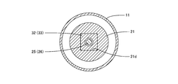
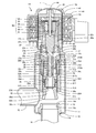
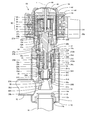
- FIG. 3 is a cross-sectional view taken along the line III-III of FIG. It is sectional drawing which follows the IV-IV line of FIG. It is a vertical sectional view of the electric valve which concerns on other embodiment of this invention (the structure which has a valve opening spring). It is a vertical sectional view of the electric valve which concerns on other embodiment of this invention (the structure which has two thrust ball bearings). It is sectional drawing of the conventional electric valve.
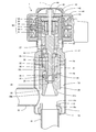
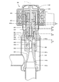
- FIG. 1 and 2 are vertical cross-sectional views (cross-sectional views along the axis L) of the electric valve according to the embodiment of the present invention.
- FIG. 1 shows a closed state of the motorized valve
- FIG. 2 shows a fully open state of the motorized valve.
- FIG. 3 is a cross-sectional view taken along the line III-III of FIG.
- FIG. 4 is a cross-sectional view taken along the line IV-IV of FIG.
- the electric valve 1 is used as an expansion valve in, for example, a heat pump type heating / cooling system.
- the electric valve 1 is a bidirectional flow type electric valve in which a fluid (refrigerant) flows in both directions.
- the electric valve 1 includes a valve body 10, a can 18, a support member 20, a rolling bearing 23, a drive shaft 25, a valve body 30, a female screw body 32, a sealing member 36, and a valve body drive unit 40. And have.
- the valve body 10 has a tubular member 11, a holder 12, and a valve seat member 13.
- the tubular member 11 has a substantially cylindrical shape.
- a valve chamber 14 is formed inside the tubular member 11.
- the holder 12 has a stepped substantially cylindrical shape in which the outer diameter of the lower part is larger than the outer diameter of the upper part.
- the lower portion of the holder 12 is fitted into the upper end opening 11a of the tubular member 11.
- the tubular member 11 and the holder 12 are welded together.
- the length of the portion of the holder 12 arranged inside the tubular member 11 in the axis L direction is set to a length that maintains the fitting relationship between the holder 12 and the tubular member 11 even after welding. There is. Inside the holder 12, an annular planar holding surface 12a facing downward is formed.
- the valve seat member 13 has a substantially cylindrical shape.
- the valve seat member 13 is housed in the valve chamber 14.
- the lower portion of the valve seat member 13 is fitted into the lower end opening 11b of the tubular member 11.
- the tubular member 11 and the valve seat member 13 are brazed.
- the valve seat member 13 has a valve opening 13a which is a circular hole.
- the valve opening 13a is open to the valve chamber 14.
- An annular valve seat 13b is formed on the inner edge of the upper end of the valve seat member 13.
- the valve seat 13b surrounds the valve opening 13a.
- the first conduit 15 is brazed to the tubular member 11.
- the first conduit 15 penetrates the tubular member 11 in the lateral direction (direction orthogonal to the axis L) and is connected to the valve chamber 14.
- a second conduit 16 is brazed to the valve seat member 13.
- the second conduit 16 is connected to the valve opening 13a. It is desirable that the length of the portion of the first conduit 15 arranged inside the tubular member 11 is such that the molten wax (fillet) does not flow into the first conduit 15 from the valve chamber 14 side.
- the can 18 has a cylindrical shape with the upper end closed. The lower end of the can 18 is welded to the upper part of the holder 12.
- the support member 20 has a valve body support portion 21 and a drive shaft support portion 22.
- the valve body support portion 21 has a cylindrical shape.
- the upper portion of the valve body support portion 21 is press-fitted into the inside of the holder 12.
- the lower portion of the valve body support portion 21 is arranged at a distance from the valve seat member 13 in the vertical direction (axis L direction).
- the lower portion of the valve body support portion 21 faces the valve seat member 13 in the vertical direction.
- the valve body support portion 21 has a partition wall 21a.
- the partition wall 21a vertically partitions the inner space of the valve body support portion 21.
- the space above the partition wall 21a is the spring chamber 21b.
- the space below the partition wall 21a is the valve body guide hole 21c.
- a square support hole 21d is formed in the partition wall 21a.
- the upper portion 22a of the drive shaft support portion 22 has a cylindrical shape.
- the lower portion 22b of the drive shaft support portion 22 has a cylindrical shape.
- a shaft hole 22c that penetrates in the vertical direction is formed in the upper portion 22a of the drive shaft support portion 22.
- an annular protrusion 22d that projects outward in the radial direction is formed.
- the protrusion 22d is held between the holding surface 12a of the holder 12 and the upper portion of the valve body support portion 21 press-fitted inside the holder 12.
- the lower portion 22b of the drive shaft support portion 22 defines the spring chamber 21b together with the valve body support portion 21.
- An annular planar receiving surface 22e facing downward is formed inside the lower portion 22b of the drive shaft support portion 22.
- the rolling bearing 23 is a radial ball bearing.
- balls 23c which are a plurality of rolling elements, are arranged between the outer ring 23a and the inner ring 23b.
- the rolling bearing 23 is arranged inside the lower portion 22b of the drive shaft support portion 22.
- the upper end of the outer ring 23a is in contact with the receiving surface 22e of the lower portion 22b of the drive shaft support portion 22.
- a compressed holding spring 24 is arranged between the lower end of the outer ring 23a and the partition wall 21a.
- the outer ring 23a is pressed against the receiving surface 22e by the holding spring 24.
- the holding spring 24 applies pressurization to the outer ring 23a.
- a thrust bearing may be used as the rolling bearing 23.
- the drive shaft 25 is arranged along the vertical direction.
- the drive shaft 25 integrally has a male screw portion 26 and a base portion 27.
- the drive shaft 25 is formed by cutting a block of metal material such as a stainless steel material, for example.
- the male threaded portion 26 has a cylindrical shape.
- a male screw 26c is formed on the outer peripheral surface of the male screw portion 26.
- the base portion 27 has a first shaft portion 27a, a second shaft portion 27b, and a connection portion 27c.
- the first shaft portion 27a has a cylindrical shape.
- the first shaft portion 27a is continuously provided at the upper end of the male screw portion 26.
- the diameter of the first shaft portion 27a is larger than that of the male screw portion 26 and is the same as the inner diameter of the inner ring 23b of the rolling bearing 23.
- the first shaft portion 27a is inserted into the inner ring 23b.
- the first shaft portion 27a is arranged inside the inner ring 23b.
- the first shaft portion 27a is rotatably supported by the rolling bearing 23 around the axis L.
- the second shaft portion 27b has a cylindrical shape.
- the second shaft portion 27b is continuously provided at the upper end of the first shaft portion 27a.
- the diameter of the second shaft portion 27b is larger than that of the first shaft portion 27a and is the same as the inner diameter of the shaft hole 22c of the drive shaft support portion 22.
- the second shaft portion 27b is inserted into the shaft hole 22c.
- the second shaft portion 27b is arranged in the shaft hole 22c.
- the second shaft portion 27b is rotatably supported by the drive shaft support portion 22 around the axis L.
- the inner ring 23b of the rolling bearing 23 is held between the second shaft portion 27b and the nut 28 screwed to the male screw portion 26.
- the pressurization applied to the inner ring 23b is adjusted according to the degree of tightening of the nut 28.
- the connecting portion 27c protrudes from the upper surface of the second shaft portion 27b.
- the connecting portion 27c has a cylindrical shape or a prismatic shape.
- the connecting portion 27c is connected to the planetary gear mechanism 50 included in the valve body driving portion 40.
- the valve body 30 opens and closes the valve opening 13a.
- the valve body 30 has a substantially cylindrical shape.
- the outer diameter of the valve body 30 is the same as the diameter of the valve body guide hole 21c of the support member 20.
- the valve body 30 is inserted into the valve body guide hole 21c.
- the valve body 30 is arranged in the valve body guide hole 21c.
- the space above the valve body 30 in the valve body guide hole 21c becomes the back pressure chamber 29.
- the valve body 30 can slide and move in the vertical direction in the valve body guide hole 21c.
- the valve body 30 faces the valve seat member 13 in the vertical direction.
- the valve body 30 is guided to move in the vertical direction by the support member 20.
- the support member 20 supports the valve body 30 with respect to the valve opening 13a so as to be able to advance and retreat.
- the female screw body 32 has a substantially square tubular shape.
- the female screw body 32 has a main body portion 33 made of synthetic resin and a metal press-fitting frame portion 34.
- the main body portion 33 and the press-fitting frame portion 34 are integrated by insert molding.
- the main body 33 has a substantially square cylinder shape.
- the outer shape of the cross section of the main body 33 is square.
- the shape of the support hole 21d of the support member 20 is also a square shape having the same shape as the outer shape of the cross section of the main body 33.
- the main body 33 is inserted into the support hole 21d.
- the main body 33 is arranged in the support hole 21d.
- "valve body 30 and valve body guide hole 21c" "main body portion 33 and support hole 21d”, "second shaft portion 27b of drive shaft 25 and shaft hole 22c of drive shaft support portion 22”, etc.
- the "same" shape (diameter, outer shape) of the configurations having an insertion relationship includes that one is slightly smaller than the other and is the same to the extent that it can be moved in the insertion direction.
- the outer shape of the cross section of the main body 33 and the shape of the support hole 21d may be other polygonal shapes such as a regular hexagonal shape.
- the main body 33 arranged in the support hole 21d is restricted from rotating around the axis L and can move in the axis L direction. That is, the support member 20 restricts the rotation around the axis L and supports the main body 33 so as to be movable in the axis L direction.
- the upper part of the main body portion 33 is the female screw portion 33a.
- a female screw 33c is formed on the inner peripheral surface of the female screw portion 33a.
- the female screw 33c is screwed into the male screw 26c of the drive shaft 25.
- Lubricant can be omitted at the screwing points of the female screw 33c of the main body 33 made of synthetic resin and the male screw 26c of the metal drive shaft 25.
- the main body portion 33 has a lateral hole 33b formed below the female screw portion 33a.
- the lateral hole 33b penetrates from the outer peripheral surface to the inner peripheral surface of the main body 33.
- the lateral hole 33b is connected to the inner space 33d of the main body 33.
- the inner space 30d of the valve body 30, the inner space 33d of the main body 33, and the lateral hole 33b form a pressure equalizing passage 39.
- the pressure equalizing passage 39 connects the valve port 13a and the back pressure chamber 29 in the closed state.
- the press-fitting frame portion 34 has a tubular portion 34a and a flange portion 34b.
- the outer shape of the cross section of the tubular portion 34a is square.
- the tubular portion 34a is embedded in the lower part of the main body portion 33.
- the tubular portion 34a is press-fitted into the square hole 30c of the upper surface 30a of the valve body 30.
- the female screw body 32 is fixed to the valve body 30.
- the flange portion 34b has an annular plate shape.
- the flange portion 34b projects radially outward from the upper end of the tubular portion 34a.
- the flange portion 34b is arranged on the upper surface 30a of the valve body 30.
- the flange portion 34b forms an annular groove 35 together with a notched step portion arranged on the peripheral edge of the upper surface 30a of the valve body 30.
- the annular groove 35 holds the annular sealing member 36.
- the sealing member 36 is arranged between the valve body 30 and the support member 20 in a state of being compressed in the radial direction.
- the sealing member 36 closes between the valve body 30 and the support member 20.
- the sealing member 36 separates the valve chamber 14 and the back pressure chamber 29.
- the sealing member 36 has a sealing portion and an outer cap portion.
- the seal portion is a ring-shaped member made of a rubber-like elastic material (such as a rubber material or a synthetic resin material having rubber-like elasticity).
- the seal portion is, for example, an O-ring.
- the outer cap portion is an annular band-shaped member made of a synthetic resin such as polytetrafluoroethylene (PTFE), which has less elastic deformation than the sealing portion.
- PTFE polytetrafluoroethylene
- the outer cap portion covers the outer peripheral portion of the seal portion.
- the outer peripheral surface of the outer cap portion is in contact with the inner peripheral surface of the valve body guide hole 21c. When the valve body 30 moves in the vertical direction, the outer peripheral surface of the outer cap portion slides with the inner peripheral surface of the valve body guide hole 21c.
- the material of the outer cap portion is selected in consideration of slidability, foreign matter resistance, and wear resistance.
- the sealing member 36 may not have an external cap portion but may have only
- the valve body driving unit 40 moves the valve body 30 in the vertical direction to bring the valve body 30 into contact with and separate from the valve seat 13b of the valve seat member 13.
- the valve body drive unit 40 has a stator 42, a rotor 43, a rotor shaft 44, a connecting member 45, and a planetary gear mechanism 50.
- the stator 42 is arranged outside the can 18.
- the rotor 43 is rotatably arranged inside the can 18.
- the rotor 43 is connected to the rotor shaft 44 via a disk-shaped connecting member 45.
- the stator 42 and the rotor 43 form an electric motor.
- the planetary gear mechanism 50 slows down the rotation of the rotor 43.
- the planetary gear mechanism 50 is arranged inside the rotor 43.
- the planetary gear mechanism 50 includes a gear case 51, a sun gear 52, a fixed ring gear 53, a plurality of planetary gears 54, a carrier 55, and an output gear 56 which is an output unit.
- the gear case 51 has a cylindrical shape.
- the gear case 51 is fixed to the upper part of the support member 20.
- the sun gear 52 is integrated with the connecting member 45.
- a rotor shaft 44 is inserted inside the sun gear 52.
- the fixed ring gear 53 is an internal gear and is fixed to the upper end of the gear case 51.
- the plurality of planetary gears 54 surround the sun gear 52.
- the planetary gear 54 meshes with the sun gear 52 and the fixed ring gear 53.
- the carrier 55 rotatably supports the planetary gear 54.
- the output gear 56 is an internal gear having a bottomed cylinder shape.
- the output gear 56 meshes with the planetary gear 54.
- the connection portion 27c of the drive shaft 25 is press-fitted into the through hole at the bottom of the output gear 56.
- the drive shaft 25 rotates together with the output gear 56.
- the electric valve 1 has a 3K type planetary gear mechanism 50 as a reduction mechanism.
- the electric valve 1 may employ another type of reduction mechanism.
- a 2K-H type planetary gear mechanism having two or more stages or a reduction mechanism having a worm gear (worm and worm wheel) may be adopted.
- the tubular member 11, the holder 12, the valve seat member 13 (valve opening 13a, valve seat 13b), the support member 20 (valve body guide hole 21c, support hole 21d, shaft hole 22c), rolling bearing 23,
- the axes of the drive shaft 25, the valve body 30, the rotor shaft 44, and the output gear 56 coincide with the axis L.
- the axis L direction is also the advancing / retreating direction of the valve body 30.
- a rotational force is generated in the rotor 43 by passing an electric current through the stator 42.
- the rotational force of the rotor 43 is decelerated by the planetary gear mechanism 50 and transmitted from the output gear 56 to the drive shaft 25.
- the drive shaft 25 rotates, the female screw body 32 moves up and down according to the rotation direction due to the screw feed action.
- the valve body 30 moves up and down together with the female screw body 32.
- valve body 30 When the female screw body 32 moves downward, the valve body 30 also moves downward.
- the lower end 30b of the valve body 30 comes into contact with the valve seat 13b and the valve opening 13a closes (valve closed state).
- valve closed state In the closed state, the valve port 13a and the back pressure chamber 29 are connected through the pressure equalizing passage 39. Therefore, the upward fluid pressure and the downward fluid pressure applied to the valve body 30 are canceled.
- valve body 30 When the female screw body 32 moves upward in the closed state, the valve body 30 also moves upward. The lower end 30b of the valve body 30 is separated from the valve seat 13b and the valve opening 13a is opened (valve open state). Then, as shown in FIG. 2, when the valve body 30 moves to the upper limit position farthest from the valve seat 13b, the electric valve 1 is fully opened. In the fully open state, the male screw portion 26 of the drive shaft 25 enters the inner space 33d of the female screw body 32 to a position where the lateral hole 33b of the female screw body 32 is closed. As a result, the pressure equalizing passage 39 is blocked by the male screw portion 26.
- the drive shaft 25 is rotatably supported by the rolling bearing 23.
- the female threaded body 32 fixed to the valve body 30 is screwed into the male threaded portion 26 of the drive shaft 25.
- the support member 20 restricts the rotation around the axis L and supports the female screw body 32 so as to be movable in the axis L direction. Therefore, when the drive shaft 25 connected to the planetary gear mechanism 50 rotates, the female screw body 32 moves in the axis L direction due to the screw feed action. A force in the axis L direction is applied to the drive shaft 25 as the female screw body 32 moves, and this force is distributed to the plurality of balls 23c of the rolling bearing 23.
- the electric valve 1 can prevent concentration of force and improve durability. Further, the valve body 30 is advanced and retracted with respect to the valve opening 13a by the screw feeding action. Therefore, the electric valve 1 can reduce the power consumption as compared with the configuration having the valve opening spring.
- the support member 20 has a valve body guide hole 21c in which the valve body 30 is arranged.
- the female screw body 32 has a lateral hole 33b penetrating from the outer peripheral surface to the inner peripheral surface.
- the inner space 30d of the valve body 30, the inner space 33d of the female screw body 32, and the lateral hole 33b form a pressure equalizing passage 39 connecting the valve port 13a and the back pressure chamber 29 in the valve closed state.
- the drive shaft 25 has a base 27 integrally connected to the male screw portion 26 and connected to the output gear 56 of the planetary gear mechanism 50.
- the rolling bearing 23 is a radial ball bearing.
- the outer ring 23a of the rolling bearing 23 is held by the support member 20.
- the inner ring 23b is held between the second shaft portion 27b of the base portion 27 and the nut 28 screwed to the male screw portion 26.
- the drive shaft 25 can be supported by the rolling bearing 23 with a simple configuration in which the male screw portion 26 and the nut 28 are combined. Further, by using the nut 28, it becomes easier to manage the pressurization of the inner ring 23b as compared with the configuration in which the drive shaft 25 is press-fitted into the inner ring 23b of the rolling bearing 23.
- the outer shape of the cross section of the female screw body 32 is square.
- the valve body support portion 21 of the support member 20 has a partition wall 21a that partitions the inner space thereof in the L direction of the axis.
- the partition wall 21a has a support hole 21d in which the female screw body 32 is arranged.
- the support hole 21d has the same square shape as the outer shape of the cross section of the female screw body 32.
- the electric valve 1 has a distance D1 between the nut 28 and the female screw body 32, and a distance D2 between the partition wall 21a of the support member 20 and the female screw body 32. ..
- the maximum amount of movement of the valve body 30 is limited to the smallest of the intervals D1 and D2 when the valve is closed.
- a distance E3 from the receiver 961, a distance E4 between the bearing member 922 and the thrust transmission member 963, and a distance E5 between the valve body 930 and the partition wall 921a are provided.
- the maximum amount of movement of the valve body 930 is limited to the smallest interval E1 to E5 when the valve is closed.
- the two intervals (intervals D1 and D2) may be set to ⁇ or more, but in the conventional electric valve 901, the intervals are five. It is necessary to set all of (intervals E1 to E5) to ⁇ or more. Therefore, when the electric valve 1 according to the present embodiment has the same size as the conventional electric valve 901, the maximum movement amount of the valve body 30 can be made larger than that of the electric valve 901.
- the electric valve 1A shown in FIG. 5 has a support member 20A, a valve body 30A, and a female screw body 32A.
- the support member 20A has a valve body support portion 21A and a drive shaft support portion 22.
- the valve body support portion 21A has a first member 211 and a second member 212.
- the first member 211 has a substantially cylindrical shape.
- the upper part of the first member 211 is press-fitted into the inside of the holder 12.
- the lower portion of the first member 211 is arranged at a distance from the valve seat member 13 in the vertical direction.
- the lower portion of the first member 211 faces the valve seat member 13 in the vertical direction.
- the inner space of the first member 211 is a valve body guide hole 21c in which the valve body 30A is arranged.
- An annular planar spring receiving surface 211a facing upward is formed on the inner peripheral surface of the first member 211.
- the second member 212 has a tubular portion 212a and a flange portion 212b.
- the tubular portion 212a is arranged inside the first member 211.
- the outer shape of the cross section of the tubular portion 212a is circular, and the inner shape is square.
- the inner space of the tubular portion 212a is a support hole 21d in which the female screw body 32A is arranged.
- the flange portion 212b has an annular shape.
- the flange portion 212b projects radially outward from the upper end of the tubular portion 212a.
- the outer peripheral edge of the flange portion 212b is joined to the upper end of the first member 211.
- the second member 212 regulates the rotation of the female screw body 32A around the axis L.
- the inner ring 23b of the rolling bearing 23 is held between the second shaft portion 27b of the drive shaft 25 and the retaining ring 28A fitted in the groove of the first shaft portion 27a.
- the valve body 30A opens and closes the valve opening 13a.
- the valve body 30A has a substantially cylindrical shape.
- the outer diameter of the valve body 30A is the same as the diameter of the valve body guide hole 21c of the support member 20A.
- the valve body 30A is inserted into the valve body guide hole 21c.
- the valve body 30A is arranged in the valve body guide hole 21c.
- the valve body 30A can slide and move in the vertical direction in the valve body guide hole 21c.
- the valve body 30A faces the valve seat member 13 in the vertical direction.
- the valve body 30A is guided to move in the vertical direction by the support member 20A.
- the support member 20A supports the valve body 30A with respect to the valve opening 13a so as to be able to advance and retreat.
- the female screw body 32A has a main body portion 33A and a press-fitting frame portion 34A.
- the main body 33A has a substantially square cylinder shape.
- the outer shape of the cross section of the main body 33A is square.
- the shape of the support hole 21d of the support member 20A is also a square shape having the same shape as the outer shape of the cross section of the main body portion 33A.
- the main body 33A is inserted into the support hole 21d.
- the main body 33A is arranged in the support hole 21d.
- the support member 20A (second member 212) supports the main body 33A so as to restrict rotation around the axis L and to move in the axis L direction.
- the upper part of the main body portion 33A is the female screw portion 33a.
- a female screw 33c is formed on the inner peripheral surface of the female screw portion 33a.
- the female screw 33c is screwed into the male screw 26c of the drive shaft 25.
- the main body portion 33A has a lateral hole 33b formed below the female screw portion 33a.
- the lateral hole 33b penetrates from the outer peripheral surface to the inner peripheral surface of the main body 33A.
- the lateral hole 33b is connected to the inner space 33d of the main body 33A.
- the inner space 30d of the valve body 30A, the inner space 33d of the main body 33A, and the lateral hole 33b form a pressure equalizing passage 39.
- the pressure equalizing passage 39 connects the valve port 13a and the back pressure chamber 29 in the closed state.
- the press-fitting frame portion 34A has a tubular portion 34c and a flange portion 34d.
- the lower part of the main body portion 33A is arranged inside the lower part of the tubular portion 34c.
- the lower portion of the tubular portion 34c is press-fitted into the hole 30c of the upper surface 30a of the valve body 30A.
- the female screw body 32A main body portion 33A and press-fitting frame portion 34A
- a filter 37A is arranged between the valve body 30A and the main body portion 33A.
- the filter 37A captures foreign matter contained in the fluid flowing through the pressure equalizing passage 39.
- the flange portion 34d has an annular plate shape.
- the flange portion 34d projects radially outward from the upper end of the tubular portion 34c.
- the flange portion 34d is arranged at a distance in the vertical direction from the spring receiving surface 211a of the first member 211.
- a compressed valve opening spring 38A is arranged between the flange portion 34d and the spring receiving surface 211a. The flange portion 34d (that is, the valve body 30A) is pushed upward by the valve opening spring 38A.
- the space in the valve body guide hole 21c where the press-fitting frame portion 34A is arranged becomes the back pressure chamber 29.
- the sealing member 36 is held in the annular groove 35A formed by the valve body 30A and the female threaded body 32A.
- the sealing member 36 is arranged in a state of being compressed in the radial direction between the female screw body 32A (press-fitting frame portion 34A) and the support member 20A (first member 211).
- the sealing member 36 closes between the valve body 30A and the support member 20A.
- the sealing member 36 separates the valve chamber 14 and the back pressure chamber 29.
- the electric valve 1B shown in FIG. 6 has a support member 20B, a valve body 30A, a female screw body 32A, two rolling bearings 23B, and a drive shaft 25B.
- the support member 20B has a valve body support portion 21A and a drive shaft support portion 22B.
- the drive shaft support portion 22B has a substantially cylindrical shape as a whole.
- An annular protrusion 22f that projects inward in the radial direction is formed at the upper end of the drive shaft support portion 22B.
- the protrusion 22f is formed with a receiving surface 22g having an annular plane shape facing downward.
- the drive shaft 25B integrally has a male screw portion 26 and a base portion 27B.
- the base portion 27B has a first shaft portion 27a, a second shaft portion 27b, a connection portion 27c, and a flange portion 27d.
- the flange portion 27d has an annular plate shape. The inner peripheral edge of the flange portion 27d is connected to the outer peripheral surface of the second shaft portion 27b.
- the two rolling bearings 23B are thrust ball bearings.
- balls 23f which are a plurality of rolling elements, are arranged between the upper track board 23d and the lower track board 23e.
- the two rolling bearings 23B are arranged side by side in the vertical direction (axis L direction) inside the drive shaft support portion 22B.
- a flange portion 27d of the drive shaft 25B is arranged between the two rolling bearings 23B.
- the upper track board 23d of the rolling bearing 23B on the upper side is in contact with the receiving surface 22g at the upper end of the drive shaft support portion 22B.
- a compression spring 24 is arranged between the lower track board 23e of the rolling bearing 23B on the lower side and the second member 212 of the support member 20B.
- the rolling bearing 23B on the lower side is pushed upward by the holding spring 24.
- the upper track board 23d of the rolling bearing 23B on the upper side is pressed against the receiving surface 22g.
- a second shaft portion 27b of the drive shaft 25B is arranged inside the two rolling bearings 23B.
- the two rolling bearings 23B rotatably support the drive shaft 25B.
- the rolling bearing 23B on the upper side mainly receives the upward force applied to the valve body 30A.
- the rolling bearing 23B on the lower side mainly receives the downward force applied to the valve body 30A.
- the electric valves 1A and 1B have the same effect as the electric valve 1 described above.
- the electric valve 1A pushes the valve body 30A upward by the valve opening spring 38A, it is possible to reduce the hysteresis characteristic when the valve body 30A moves in the vertical direction. Further, since the electric valve 1B receives the pressure applied to the valve body 30A and the drive shaft 25B by the two rolling bearings 23B, the difference between the fluid pressure on the inflow side and the fluid pressure on the outflow side is relatively large in the system. High durability can be achieved.
- the present invention is not limited to the configuration of the embodiment.
- the gist of the present invention is not contrary to the above-mentioned embodiments, those skilled in the art appropriately adding, deleting, or changing the design, or combining the features of the examples as appropriate are also present inventions. Is included in the range of.
- valve body 11 ... Cylindrical member, 11a ... Upper end opening, 11b ... Lower end opening, 12 ... Holder, 12a ... Holding surface, 13 ... Valve seat member, 13a ... Valve mouth, 13b ... Valve seat , 14 ... valve chamber, 15 ... first conduit, 16 ... second conduit, 18 ... can, 20 ... support member, 21 ... valve body support, 21a ... partition wall, 21b ... spring chamber, 21c ... valve body guide hole, 21d ... support hole, 22 ... drive shaft support part, 22a ... upper part, 22b ... lower part, 22c ... shaft hole, 22d ... protrusion, 22e ... receiving surface, 23 ...
Landscapes
- Engineering & Computer Science (AREA)
- General Engineering & Computer Science (AREA)
- Mechanical Engineering (AREA)
- Electrically Driven Valve-Operating Means (AREA)
Abstract
Description
1A、1B…電動弁、20A、20B…支持部材、21A…弁体支持部、211…第1部材、211a…ばね受け面、212…第2部材、212a…筒部、212b…フランジ部、22B…駆動軸支持部、22f…突部、22g…受け止め面、23B…転がり軸受、23d…上軌道盤、23e…下軌道盤、23f…ボール、25B…駆動軸、27B…基部、27d…フランジ部、28A…止め輪、30A…弁体、32A…雌ねじ体、33A…本体部、34A…圧入枠部、34c…筒部、34d…フランジ部、35A…環状溝、37A…フィルタ、38A…開弁ばね
Claims (4)
- 弁室および弁口を有する弁本体と、前記弁口を開閉する弁体と、前記弁体を前記弁口に対して進退可能に支持する支持部材と、を有する電動弁であって、
前記弁体の進退方向に沿って配置された、雄ねじ部を有する駆動軸と、
前記支持部材に保持され、前記駆動軸を回転可能に支持する転がり軸受と、
前記駆動軸に接続される遊星歯車機構と、
前記弁体に固定され、前記雄ねじ部に螺合する筒形状の雌ねじ体と、を有し、
前記支持部材が、前記雌ねじ体を、軸周りの回転を規制しかつ軸方向に移動可能に支持していることを特徴とする電動弁。 - 前記支持部材が、前記弁体が配置される弁体ガイド穴を有し、
前記雌ねじ体が、外周面から内周面まで貫通する横孔を有し、
前記雌ねじ体の内側空間および前記横孔が、前記弁体の一端が前記弁口の弁座に接した閉弁状態において、前記弁口と前記弁体ガイド穴における前記弁体の他端側の空間である背圧室とを接続する均圧通路であり、
前記弁体が前記弁座から最も離れた全開状態において、前記雄ねじ部が前記横孔を塞ぐ位置まで前記雌ねじ体に進入する、請求項1に記載の電動弁。 - 前記駆動軸が、前記雄ねじ部に一体的に連設されかつ前記遊星歯車機構の出力部に接続される基部を有し、
前記転がり軸受が、ラジアル玉軸受であり、
前記転がり軸受の外輪が、前記支持部材に保持され、
前記転がり軸受の内輪が、前記基部と前記雄ねじ部に螺合したナットとの間に保持されている、請求項1または請求項2に記載の電動弁。 - 前記雌ねじ体の横断面の外形が、多角形状であり、
前記支持部材が、その内側空間を軸方向に区画する隔壁を有し、
前記隔壁が、前記雌ねじ体が配置される支持孔を有し、
前記支持孔が、前記雌ねじ体の横断面の外形と同一形状を有している、請求項1~請求項3のいずれか一項に記載の電動弁。
Priority Applications (3)
| Application Number | Priority Date | Filing Date | Title |
|---|---|---|---|
| CN202180043718.7A CN115769015B (zh) | 2020-07-10 | 2021-06-16 | 电动阀 |
| EP21838181.2A EP4180699B1 (en) | 2020-07-10 | 2021-06-16 | Electric valve |
| JP2021559611A JP7034527B1 (ja) | 2020-07-10 | 2021-06-16 | 電動弁 |
Applications Claiming Priority (2)
| Application Number | Priority Date | Filing Date | Title |
|---|---|---|---|
| JP2020-119410 | 2020-07-10 | ||
| JP2020119410 | 2020-07-10 |
Publications (1)
| Publication Number | Publication Date |
|---|---|
| WO2022009632A1 true WO2022009632A1 (ja) | 2022-01-13 |
Family
ID=79552961
Family Applications (1)
| Application Number | Title | Priority Date | Filing Date |
|---|---|---|---|
| PCT/JP2021/022861 Ceased WO2022009632A1 (ja) | 2020-07-10 | 2021-06-16 | 電動弁 |
Country Status (4)
| Country | Link |
|---|---|
| EP (1) | EP4180699B1 (ja) |
| JP (1) | JP7034527B1 (ja) |
| CN (1) | CN115769015B (ja) |
| WO (1) | WO2022009632A1 (ja) |
Cited By (2)
| Publication number | Priority date | Publication date | Assignee | Title |
|---|---|---|---|---|
| CN115823267A (zh) * | 2022-11-30 | 2023-03-21 | 浙江三花智能控制股份有限公司 | 一种电子膨胀阀 |
| WO2025074706A1 (ja) * | 2023-10-04 | 2025-04-10 | 株式会社不二工機 | 電動弁 |
Citations (4)
| Publication number | Priority date | Publication date | Assignee | Title |
|---|---|---|---|---|
| JP2000346225A (ja) * | 1999-03-26 | 2000-12-15 | Saginomiya Seisakusho Inc | 電動弁 |
| JP2013130271A (ja) | 2011-12-22 | 2013-07-04 | Fuji Koki Corp | 電動弁 |
| JP2014137127A (ja) * | 2013-01-18 | 2014-07-28 | Fuji Koki Corp | 電動弁 |
| JP2016540933A (ja) * | 2014-01-20 | 2016-12-28 | 浙江三花股▲分▼有限公司 | 直動式電動弁及びその実装方法 |
Family Cites Families (12)
| Publication number | Priority date | Publication date | Assignee | Title |
|---|---|---|---|---|
| US6460567B1 (en) * | 1999-11-24 | 2002-10-08 | Hansen Technologies Corpporation | Sealed motor driven valve |
| JP2003247654A (ja) * | 2002-02-21 | 2003-09-05 | Denso Corp | 流量制御弁 |
| CN2568883Y (zh) * | 2002-09-10 | 2003-08-27 | 刘伟 | 电动阀门 |
| WO2006064865A1 (ja) * | 2004-12-15 | 2006-06-22 | Kabushiki Kaisha Saginomiya Seisakusho | 電動式コントロールバルブ |
| JP5316236B2 (ja) * | 2009-06-08 | 2013-10-16 | パナソニック株式会社 | 遮断弁流路ユニット |
| JP5738029B2 (ja) * | 2011-03-25 | 2015-06-17 | 株式会社不二工機 | 複合弁 |
| JP5881451B2 (ja) * | 2012-02-14 | 2016-03-09 | 株式会社不二工機 | 複合弁 |
| CN204533762U (zh) * | 2015-01-08 | 2015-08-05 | 艾默生环境优化技术(苏州)有限公司 | 减速机构以及包括该减速机构的电子膨胀阀 |
| JP6527837B2 (ja) * | 2016-05-11 | 2019-06-05 | 株式会社鷺宮製作所 | 電動弁 |
| JP6721237B2 (ja) * | 2016-06-29 | 2020-07-08 | 株式会社不二工機 | 電動弁 |
| JP6877749B2 (ja) * | 2017-09-28 | 2021-05-26 | 株式会社不二工機 | 電動弁 |
| JP6643292B2 (ja) * | 2017-09-28 | 2020-02-12 | 株式会社不二工機 | 電動弁 |
-
2021
- 2021-06-16 WO PCT/JP2021/022861 patent/WO2022009632A1/ja not_active Ceased
- 2021-06-16 CN CN202180043718.7A patent/CN115769015B/zh active Active
- 2021-06-16 EP EP21838181.2A patent/EP4180699B1/en active Active
- 2021-06-16 JP JP2021559611A patent/JP7034527B1/ja active Active
Patent Citations (4)
| Publication number | Priority date | Publication date | Assignee | Title |
|---|---|---|---|---|
| JP2000346225A (ja) * | 1999-03-26 | 2000-12-15 | Saginomiya Seisakusho Inc | 電動弁 |
| JP2013130271A (ja) | 2011-12-22 | 2013-07-04 | Fuji Koki Corp | 電動弁 |
| JP2014137127A (ja) * | 2013-01-18 | 2014-07-28 | Fuji Koki Corp | 電動弁 |
| JP2016540933A (ja) * | 2014-01-20 | 2016-12-28 | 浙江三花股▲分▼有限公司 | 直動式電動弁及びその実装方法 |
Non-Patent Citations (1)
| Title |
|---|
| See also references of EP4180699A4 |
Cited By (3)
| Publication number | Priority date | Publication date | Assignee | Title |
|---|---|---|---|---|
| CN115823267A (zh) * | 2022-11-30 | 2023-03-21 | 浙江三花智能控制股份有限公司 | 一种电子膨胀阀 |
| WO2025074706A1 (ja) * | 2023-10-04 | 2025-04-10 | 株式会社不二工機 | 電動弁 |
| JP2025063433A (ja) * | 2023-10-04 | 2025-04-16 | 株式会社不二工機 | 電動弁 |
Also Published As
| Publication number | Publication date |
|---|---|
| JP7034527B1 (ja) | 2022-03-14 |
| EP4180699B1 (en) | 2025-08-06 |
| EP4180699A4 (en) | 2024-07-24 |
| CN115769015B (zh) | 2026-04-03 |
| EP4180699A1 (en) | 2023-05-17 |
| JPWO2022009632A1 (ja) | 2022-01-13 |
| CN115769015A (zh) | 2023-03-07 |
Similar Documents
| Publication | Publication Date | Title |
|---|---|---|
| EP3336396B1 (en) | Electronic expansion valve | |
| JP7034527B1 (ja) | 電動弁 | |
| EP3428491B1 (en) | Valve device | |
| JP6928484B2 (ja) | 流量制御用三方弁及びこれを用いた温度制御装置 | |
| JP6684599B2 (ja) | 流路切換弁 | |
| US20210071921A1 (en) | Electronic expansion valve | |
| EP2933540A1 (en) | Electronic expansion valve | |
| US10330214B2 (en) | Control valve | |
| CN212480175U (zh) | 一种电动阀 | |
| KR20130085038A (ko) | 전동밸브 | |
| CN107421174B (zh) | 流路切换阀 | |
| KR101876781B1 (ko) | 폐쇄 바디를 구비한 피스톤 펌프의 밸브 | |
| JP6715879B2 (ja) | 三方切換弁 | |
| CA2969903A1 (en) | Valve body and seat with tongue and groove connection | |
| CN202451895U (zh) | 截止止回阀 | |
| JP2022069831A (ja) | 電動弁および冷凍サイクルシステム | |
| CA2753980C (en) | Decompression valve | |
| CN111594628A (zh) | 一种电子膨胀阀 | |
| CN113775771A (zh) | 一种电动阀 | |
| US7694939B2 (en) | Flow rate control valve | |
| JP6791508B2 (ja) | 電動弁 | |
| JP5175135B2 (ja) | 流量制御弁 | |
| JP2005069463A (ja) | 高温用ケージ弁 | |
| JP6963662B2 (ja) | 流量制御弁、流量制御用三方弁及び温度制御装置 | |
| US10267424B2 (en) | Butterfly valve seat with seat cover |
Legal Events
| Date | Code | Title | Description |
|---|---|---|---|
| ENP | Entry into the national phase |
Ref document number: 2021559611 Country of ref document: JP Kind code of ref document: A |
|
| 121 | Ep: the epo has been informed by wipo that ep was designated in this application |
Ref document number: 21838181 Country of ref document: EP Kind code of ref document: A1 |
|
| ENP | Entry into the national phase |
Ref document number: 2021838181 Country of ref document: EP Effective date: 20230210 |
|
| NENP | Non-entry into the national phase |
Ref country code: DE |
|
| WWG | Wipo information: grant in national office |
Ref document number: 2021838181 Country of ref document: EP |