WO2022009901A1 - Instrument chirurgical, ensemble d'outils médicaux et procédé de déplacement - Google Patents
Instrument chirurgical, ensemble d'outils médicaux et procédé de déplacement Download PDFInfo
- Publication number
- WO2022009901A1 WO2022009901A1 PCT/JP2021/025519 JP2021025519W WO2022009901A1 WO 2022009901 A1 WO2022009901 A1 WO 2022009901A1 JP 2021025519 W JP2021025519 W JP 2021025519W WO 2022009901 A1 WO2022009901 A1 WO 2022009901A1
- Authority
- WO
- WIPO (PCT)
- Prior art keywords
- wire
- sleeve
- coracoid process
- spiral
- portal
- Prior art date
- Legal status (The legal status is an assumption and is not a legal conclusion. Google has not performed a legal analysis and makes no representation as to the accuracy of the status listed.)
- Ceased
Links
Images


Classifications
-
- A—HUMAN NECESSITIES
- A61—MEDICAL OR VETERINARY SCIENCE; HYGIENE
- A61B—DIAGNOSIS; SURGERY; IDENTIFICATION
- A61B17/00—Surgical instruments, devices or methods
- A61B17/56—Surgical instruments or methods for treatment of bones or joints; Devices specially adapted therefor
- A61B17/58—Surgical instruments or methods for treatment of bones or joints; Devices specially adapted therefor for osteosynthesis, e.g. bone plates, screws or setting implements
- A61B17/88—Osteosynthesis instruments; Methods or means for implanting or extracting internal or external fixation devices
-
- A—HUMAN NECESSITIES
- A61—MEDICAL OR VETERINARY SCIENCE; HYGIENE
- A61B—DIAGNOSIS; SURGERY; IDENTIFICATION
- A61B17/00—Surgical instruments, devices or methods
- A61B17/16—Instruments for performing osteoclasis; Drills or chisels for bones; Trepans
- A61B17/1662—Instruments for performing osteoclasis; Drills or chisels for bones; Trepans for particular parts of the body
- A61B17/1684—Instruments for performing osteoclasis; Drills or chisels for bones; Trepans for particular parts of the body for the shoulder
-
- A—HUMAN NECESSITIES
- A61—MEDICAL OR VETERINARY SCIENCE; HYGIENE
- A61B—DIAGNOSIS; SURGERY; IDENTIFICATION
- A61B17/00—Surgical instruments, devices or methods
- A61B17/16—Instruments for performing osteoclasis; Drills or chisels for bones; Trepans
- A61B17/17—Guides or aligning means for drills, mills, pins or wires
- A61B17/1739—Guides or aligning means for drills, mills, pins or wires specially adapted for particular parts of the body
- A61B17/1778—Guides or aligning means for drills, mills, pins or wires specially adapted for particular parts of the body for the shoulder
-
- A—HUMAN NECESSITIES
- A61—MEDICAL OR VETERINARY SCIENCE; HYGIENE
- A61B—DIAGNOSIS; SURGERY; IDENTIFICATION
- A61B17/00—Surgical instruments, devices or methods
- A61B17/56—Surgical instruments or methods for treatment of bones or joints; Devices specially adapted therefor
- A61B17/58—Surgical instruments or methods for treatment of bones or joints; Devices specially adapted therefor for osteosynthesis, e.g. bone plates, screws or setting implements
- A61B17/88—Osteosynthesis instruments; Methods or means for implanting or extracting internal or external fixation devices
- A61B17/8866—Osteosynthesis instruments; Methods or means for implanting or extracting internal or external fixation devices for gripping or pushing bones, e.g. approximators
-
- A—HUMAN NECESSITIES
- A61—MEDICAL OR VETERINARY SCIENCE; HYGIENE
- A61B—DIAGNOSIS; SURGERY; IDENTIFICATION
- A61B17/00—Surgical instruments, devices or methods
- A61B17/16—Instruments for performing osteoclasis; Drills or chisels for bones; Trepans
- A61B17/1604—Chisels; Rongeurs; Punches; Stamps
-
- A—HUMAN NECESSITIES
- A61—MEDICAL OR VETERINARY SCIENCE; HYGIENE
- A61B—DIAGNOSIS; SURGERY; IDENTIFICATION
- A61B17/00—Surgical instruments, devices or methods
- A61B17/16—Instruments for performing osteoclasis; Drills or chisels for bones; Trepans
- A61B17/1659—Surgical rasps, files, planes, or scrapers
-
- A—HUMAN NECESSITIES
- A61—MEDICAL OR VETERINARY SCIENCE; HYGIENE
- A61B—DIAGNOSIS; SURGERY; IDENTIFICATION
- A61B17/00—Surgical instruments, devices or methods
- A61B17/56—Surgical instruments or methods for treatment of bones or joints; Devices specially adapted therefor
- A61B17/58—Surgical instruments or methods for treatment of bones or joints; Devices specially adapted therefor for osteosynthesis, e.g. bone plates, screws or setting implements
- A61B17/68—Internal fixation devices, including fasteners and spinal fixators, even if a part thereof projects from the skin
- A61B17/84—Fasteners therefor or fasteners being internal fixation devices
- A61B17/86—Pins or screws or threaded wires; nuts therefor
- A61B17/864—Pins or screws or threaded wires; nuts therefor hollow, e.g. with socket or cannulated
-
- A—HUMAN NECESSITIES
- A61—MEDICAL OR VETERINARY SCIENCE; HYGIENE
- A61B—DIAGNOSIS; SURGERY; IDENTIFICATION
- A61B17/00—Surgical instruments, devices or methods
- A61B17/56—Surgical instruments or methods for treatment of bones or joints; Devices specially adapted therefor
- A61B17/58—Surgical instruments or methods for treatment of bones or joints; Devices specially adapted therefor for osteosynthesis, e.g. bone plates, screws or setting implements
- A61B17/88—Osteosynthesis instruments; Methods or means for implanting or extracting internal or external fixation devices
- A61B17/8897—Guide wires or guide pins
-
- A—HUMAN NECESSITIES
- A61—MEDICAL OR VETERINARY SCIENCE; HYGIENE
- A61B—DIAGNOSIS; SURGERY; IDENTIFICATION
- A61B17/00—Surgical instruments, devices or methods
- A61B17/56—Surgical instruments or methods for treatment of bones or joints; Devices specially adapted therefor
- A61B2017/564—Methods for bone or joint treatment
Definitions
- the present invention relates to a surgical instrument used for transplanting a coracoid process to the scapula neck, a medical instrument set equipped with the surgical instrument, and a method of transplanting the coracoid process to the scapula neck.
- a coracoid process an operation of transplanting the coracoid process of the scapula to the neck of the scapula (hereinafter referred to as a coracoid process) has been performed. If the coracoid process is performed under direct vision, there is a risk of muscle invasion and postoperative joint contracture, and if these symptoms occur in athletes, it will be difficult to return to competition. It was.
- arthroscopic coracoid process transfer is useful, and as this arthroscopic coracoid process, the transfer technique disclosed in Non-Patent Document 1 is known. There is. In this transition technique, the following steps A to G are carried out.
- Step A As shown in FIG. 32, the incision 102 is formed in the subscapularis 100 by moving the switching stick 101 penetrating the subscapularis 100 in the vertical direction (FIG. 32 (FIG. 32).
- A) shows a state before the switching stick 101 penetrates the subscapularis muscle 100
- FIG. 32B shows a state in which the switching stick 101 penetrating the subscapularis muscle 100 is tilted upward.
- FIG. 32 (C) shows a state in which the switching stick 101 penetrating the subscapularis muscle 100 is tilted downward).
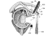
- Step B As shown in FIGS.
- the guide wire 105 is inserted into the body from the first portal 104 formed on the skin at a position directly above the coracoid process 103, and the guide wire 105 is inserted into the body. Is pierced into the coracoid process 103, and then the hollow spiral 106 is moved toward the coracoid process 103 along the guide wire 105 while the guide wire 105 is passed through the cavity of the hollow spiral 106, and is hollow in the coracoid process 103. The spiral 106 is screwed in, and then the guide wire 105 is pulled out of the body from the first portal 104 (FIG.
- Step C As shown in FIG. 34, the coracoid process 103 is cut from the scapula 108 by the bone flea 107 inserted from the first portal 104 (at this time, the coracoid process 103 with the joint tendon 109 still attached). In this state, the coracoid process 103 is cut).
- Step D As shown in FIGS.
- Step E As shown in FIGS. 36 (A) and 36 (B), the coracoid process 103 is removed from the forceps 110, and the coracoid process 103 is suspended in the body fluid, and the skin in front of the incision 102 is formed.
- a plastic cylinder 112 is inserted into the body from the second portal 111 formed at the position, and the head of the spiral 106 is inserted into the opening 113 at the tip of the cylinder 112.
- Step F As shown in FIG. 37 (A), by advancing the tubular body 112, the coracoid process 103 is inserted into the incision 102 and brought into the vicinity of the scapula neck 108a.
- Step G As shown in FIG. 37 (A), a long spiral 113 that has passed through the cavity 112a of the tubular body 112 is passed through the cavity of the spiral 106 and screwed into the coracoid process 103, and then the second step.
- the tubular body 112 is pulled out of the body from the portal 111 (FIG. 37 (B) shows a state after the tubular body 112 is pulled out of the body).
- step E the coracoid process 103 floating in the body fluid with the tubular body 112 in step E (FIG. 36) (the coracoid process 103 floats in the body fluid). It was very difficult to insert the head of the spiral 106 into the opening 113 of the tubular body 112). Therefore, in the conventional coracoid process, it takes a long time to bring the coracoid process 103 close to the scapular neck 108a. In addition, because the above step E is extremely difficult, the work under the arthroscope may be abandoned and the work may be changed to the work under the arthroscope.
- the neurovascular system 200 in the vicinity of the shoulder joint is moved back and forth by the subscapularis muscle 100 and the joint tendon 109. It is sandwiched in the direction (the above-mentioned neurovascular system 200 includes a myocutaneous nerve 200a, an axillary nerve 200b, a subscapularis artery 200c, and the like). And if this pinch is tight, complications may occur due to damage to the neurovascular system 200. For example, if the musculocutaneous nerve 200a is damaged due to the tight pinching, a complication that the elbow does not bend may occur. Further, when the axillary nerve 200b is paralyzed due to the tight pinching, a complication that the shoulder cannot be raised may occur.
- the present invention has been made in view of the above matters, and an object of the present invention is a surgical instrument capable of easily realizing a coracoid process close to the scapular neck, and a medical device provided with the surgical instrument. It is to provide a set of equipment. Another object of the present invention is to provide a method for transplanting a coracoid process, which allows the coracoid process to be brought close to the scapular neck without damaging the neurovascular system.
- the present invention includes the subjects described in the following sections.
- Item 1 A surgical instrument used to transplant the coracoid process into the neck of the scapula. With a handle that extends in the first direction, With an inclined portion extending in the second direction from the tip of the handle, The second direction in which the inclined portion extends is inclined at an angle of 95 ° or more and 115 ° or less with respect to the first direction in which the handle extends. A surgical instrument in which a notch through which a spiral is passed is formed on the outer edge of the inclined portion.
- Item 2 The surgical instrument according to Item 1, wherein a through hole through which a spiral is passed is formed in the inclined portion.
- Item 3 The surgical instrument according to Item 2, wherein an outwardly projecting protrusion is formed at a lateral position of the through hole in the inclined portion.
- the handle has a grip portion, which is a handle, connected to the base end side of the handle body.
- the inclined portion extends from the tip of the handle body in the second direction.
- Item 6. The surgical instrument according to any one of Items 1 to 3, wherein the length of the range of the handle body between the grip portion and the inclined portion is 8 cm or more and 12 cm or less.
- the surgical instrument according to Item 4 and Including cutting tools used to cut the coracoid process The cutting tool is a series of a thick portion used as a handle and a thin portion having a thickness thinner than the thick portion, and the tip of the thin portion farthest from the thick portion is formed. It is said to be the thinnest cutting edge, A medical device set in which the length of the thin portion is 6 cm or more and 8 cm or less.
- Item 6 The surgical instrument according to any one of Items 1 to 4 and With the first wire, With the second wire, With the third wire, A medical device set that includes a first sleeve
- the first wire, the second wire, the third wire, and the first sleeve can each be passed through the notch of the surgical instrument.
- the first wire is a hollow cylinder, and the third wire can be inserted into the cavity of the first wire, and a groove extending spirally on the outer peripheral surface of the tip end portion of the first wire. Is formed,
- the tip of the second wire has a rounded shape.
- the tip of the third wire is tapered with corners.
- the first sleeve is a hollow tubular body, and a medical device set capable of inserting the first wire, the second wire, and the third wire into the cavity of the first sleeve. ..
- Item 7 The surgical instrument according to any one of Items 1 to 4 and Polishing tools and With the second sleeve, With the third sleeve, With the fourth sleeve With the 4th wire
- a medical device set that includes a fifth wire The second sleeve, the third sleeve, the fourth sleeve, and the polishing tool are hollow cylinders, respectively. Inserting the third sleeve into the cavity of the second sleeve, inserting the fourth sleeve into the cavity of the third sleeve, and inserting the fourth wire or the fifth wire into the cavity of the fourth sleeve. And it is possible to insert the polishing tool into the cavity of the second sleeve.
- the fourth wire can be inserted into the cavity of the polishing tool and the cavity of the fourth sleeve, and the tip of the fourth wire has a rounded shape.
- the fifth wire can be inserted through the cavity of the polishing tool, the cavity of the fourth sleeve, and the notch of the surgical instrument, and the tip of the fifth wire is tapered with a corner.
- the polishing tool With the base end of the polishing tool connected to the power tool, the polishing tool can be rotated around the central axis by operating the power tool, and the tip surface of the polishing tool is placed on the shoulder.
- a medical device set capable of polishing the surface of the scapula neck with the tip surface of the polishing tool by rotating the polishing tool in contact with the surface of the scapula neck.
- Item 8 The medical device set according to Item 7, wherein the tip of the third sleeve and the tip of the fourth sleeve each exhibit a tapered shape.
- Item 9 A method of transplanting the coracoid process into the scapular neck using the surgical instrument according to any one of Items 1 to 4.
- a spiral inserted into the body from the first portal is passed through a notch in the inclined portion and screwed into the coracoid process, whereby the inclined portion is fastened to the coracoid process by the one spiral.
- the screw of the one spiral into the coracoid process is released, and the one spiral is taken out of the body from the second portal formed on the skin at the position in front of the incision, and from the one spiral.
- the sixth step in which a long two spiral is inserted into the body from the second portal, passed through the notch, and screwed into the coracoid process and the scapula neck.
- a method comprising a seventh step of removing the surgical instrument from the two spirals by moving the surgical instrument and taking the surgical instrument out of the body from the first portal.
- one guide wire inserted into the body from the first portal is passed through the notch of the inclined portion and pierced into the coracoid process, and then the one is inserted into the one spiral cavity. With the guide wire passed, the one spiral is moved toward the notch along the one guide wire, and the one helix is passed through the notch and screwed into the coracoid process. After that, the one guide wire is pulled out of the body from the first portal.
- the second guide wire is inserted into the body from the second portal, the second guide wire is passed through the cavity of the first spiral, and the scapula neck is pierced, and then the second guide wire is pierced.
- the one spiral is unscrewed into the coracoid process, and the one spiral is moved along the two guide wires to be taken out of the body from the second portal, and then the one.
- the second guide wire passed through the cavity of the second spiral, which is longer than the second spiral, the second spiral is moved toward the notch along the second guide wire.
- Item 9 The item 9 in which the spiral is screwed into the coracoid process and the scapula neck through the notch, and then the second guide wire is pulled out of the body from the second portal.
- the surgical instrument is the surgical instrument according to Item 2 or 3. Further having an eighth step carried out after the seventh step, In the third step, the three spirals inserted into the body from the first portal are passed through the through hole and screwed into the coracoid process, whereby the inclined portion is made into the coracoid process by the three spirals. It is done to conclude, In the sixth step, the screwing of the three spirals into the coracoid process is released, and the three spirals are taken out of the body from the second portal. In the eighth step, four spirals longer than the three spirals are inserted into the body from the second portal, and the four spirals are screwed into the coracoid process. Item 9. The method according to Item 9 or 10, wherein the screw is passed through the hole of the protrusion and screwed into the coracoid process and the scapular neck.
- the three guide wires inserted into the body from the first portal are passed through the through hole and pierced into the coracoid process, and then the three guide wires are inserted into the three spiral cavities.
- the three spirals are moved toward the through hole along the three guide wires, and the three spirals are passed through the through hole and screwed into the coracoid process, and then , The three guide wires are pulled out of the body from the first portal.
- the four guide wires are inserted into the body from the second portal, the four guide wires are passed through the cavity of the three spirals, and the scapula neck is pierced, and then the scapula neck is pierced.
- the three spirals are unscrewed into the coracoid process, and the three spirals are moved along the four guide wires to be taken out of the body from the second portal and the four guides.
- the wire is pulled out of the body from the second portal.
- the five guide wires are inserted into the body from the second portal, and the five guide wires are inserted into the hole of the coracoid process into which the three spirals are screwed and the four.
- the guide wire was passed through the hole in the neck of the scapula where the guide wire was pierced, and then the guide wire of the five was passed through the cavity of the four spirals, which was longer than the three spirals.
- the inclined portion is inclined at an angle of 95 ° or more and 115 ° or less with respect to the handle body, so that the position directly above the coracoid process suitable for forming a portal.
- the slope can be brought into contact with the coracoid process attached to the scapula under the condition that the handle passes through. Then, if the inclined portion is brought into contact with the coracoid process in this way, the work of screwing the spiral into the coracoid process through the notch can be performed while the coracoid process is attached to the scapula and is stable. .. Therefore, it is possible to easily connect the inclined portion to the coracoid process using a spiral.
- the coracoid process can be brought closer to the scapula neck by a simple operation of moving the surgical instrument downward. can.
- the coracoid process can be easily brought close to the scapular neck.
- the joint tendon and the coracoid process move downward as the surgical instrument is moved downward in the fifth step to bring the coracoid process closer to the scapular neck.
- Pression of the tendon or coracoid process can move the neurovascular system in the vicinity of the scapula downward. This makes it possible to weaken the anterior-posterior (horizontal) neurovascular system pinch between the subscapularis muscle and the joint tendon, so that the coracoid process is closer to the scapular neck without damaging the neurovascular system. Can be made to. This avoids complications due to damage to the neurovascular system.
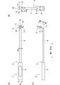
- FIG. 1 It is a perspective view (photograph) of the surgical instrument which concerns on embodiment of this invention.
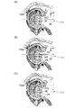
- A is a plan view showing a state in which the surgical instrument is viewed from a direction perpendicular to the handle, and
- B is a plan view showing a state in which the surgical instrument is viewed from a direction perpendicular to the inclined portion.
- C is a side view of the surgical instrument. It is a schematic diagram which shows the procedure of the method of transplanting the coracoid process which concerns on embodiment of this invention. It is a schematic diagram which shows the procedure of the method of transplanting the coracoid process which concerns on embodiment of this invention.
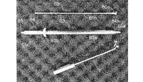
- (A) is a plan view of the cutting tool
- (B) is a side view of the cutting tool.
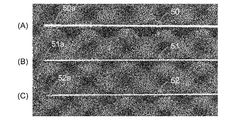
- (A) is a side view of the first wire
- (B) is a side view of the second wire
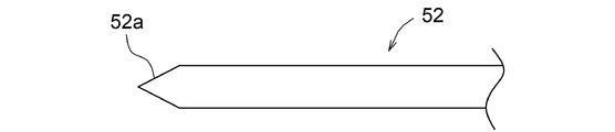
- (C) is a side view of the third wire.
- It is a side view of the first sleeve.
- It is a schematic side view which shows the tip part of the 1st wire.
- It is a schematic side view which shows the tip part of the 2nd wire.
- FIG. 1 is a perspective view (photograph) showing a surgical instrument 1 according to an embodiment of the present invention.
- FIG. 2A is a plan view showing a state in which the surgical instrument 1 is viewed from a direction perpendicular to the handle 2 described later.
- FIG. 2B is a plan view showing a state in which the surgical instrument 1 is viewed from a direction perpendicular to the inclined portion 3 described later.
- FIG. 2C is a side view of the surgical instrument 1.
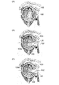
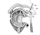
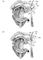
- 3 to 10 are schematic views showing a procedure of a method of transplanting a coracoid process 103 performed under arthroscopy using a surgical instrument 1.
- the surgical instrument 1 (FIGS. 1 and 2) according to the present embodiment is used for transplanting the coracoid process 103 to the scapular neck 108a (specifically, the surgical instrument 1 has the coracoid process 103 on the shoulder. Used to spirally secure the coracoid process 103 to the scapular neck 108a in close proximity to the scapular neck 108a).
- the surgical instrument 1 includes a handle 2 extending in the first direction and an inclined portion 3 extending in the second direction from the tip of the handle 2.
- the second direction in which the inclined portion 3 extends is inclined at an angle ⁇ of 95 ° or more and 115 ° or less with respect to the first direction in which the handle 2 extends (see FIG. 2C for the angle ⁇ ).
- the handle 2 has a grip portion 5 as a handle connected to the base end side of the handle body 4.
- the grip portion 5 is a tubular body having an opening 6 (FIG. 2 (B)) at the tip (one end), and is formed of a stainless alloy, a titanium alloy, or an aluminum alloy.
- the length L1 (FIG. 1) of the grip portion 5 is set to, for example, 5 cm or more.
- the width H1 (FIG. 2A) of the grip portion 5 is, for example, 1 cm or more and 2 cm or less.
- the handle body 4 is a bar made of a stainless alloy, a titanium alloy, or an aluminum alloy.
- the cross section of the handle body 4 has a rectangular shape, and the dimensions (width, height) of the cross section of the grip portion 5 are larger than the dimensions (width, height) of the cross section of the handle body 4.
- the base end side of the handle body 4 grips the handle body 4 with the base end side of the handle body 4 inserted into the grip portion 5 from the opening 6 of the grip portion 5. It is performed by being fixed to the portion 5.
- the inclined portion 3 extends from the tip of the handle main body 4, and the length L2 (FIG.
- the width H2 (FIG. 2A) of the handle body 4 is, for example, 0.4 cm or more and 0.8 cm or less.
- the shape of the cross section of the handle body 4 may be a shape other than a rectangle (for example, the cross section of the handle body 4 may be circular or elliptical).
- the grip portion 5 may be connected to the base end side of the handle body 4 by a known method other than the above. Further, the grip portion 5 may be integrally molded with the handle body 4 so as to be connected to the base end side of the handle body 4. Also in this case, the dimensions (width, height) of the cross section of the grip portion 5 are larger than the dimensions (width, height) of the cross section of the handle body 4.
- the inclined portion 3 is a plate-shaped body extending in the second direction from the tip of the handle body 4.
- the inclined portion 3 is formed of a stainless alloy, a titanium alloy, or an aluminum alloy, and is integrally molded with the handle body 4.
- the length L3 (FIG. 1) of the inclined portion 3 is, for example, 1.5 cm or more and 2.5 cm or less, and the width H3 of the inclined portion 3 (FIG. 2 (B)) is, for example, 1.2 cm or more and 1.5 cm or less.
- the width H3 of the inclined portion 3 means the maximum width of the inclined portion 3).
- a notch 10 through which a spiral is passed is formed on the outer edge of the inclined portion 3 on the tip end side.
- the notch 10 opens outward, and is a spiral 21 screwed into the coracoid process 103 (FIGS. 5 to 8) and a spiral 26 screwed into the coracoid process 103 and the scapula neck 108a (FIG. 5 to 8). 8 to 10) are passed through the notch 10.
- the bifurcated portions 11 and 11 are formed on the tip end side of the inclined portion 3, and the notch 10 is formed by the space between the bifurcated portions 11 and 11, and the notch is formed.
- the cross section of 10 has a semicircular shape.
- a through hole 12 through which a spiral is passed is formed on the base end side (handle 2 side) of the inclined portion 3.
- the cross section of the through hole 12 has a circular shape, and the spiral 23 (FIGS. 5 to 8) screwed into the coracoid process 103 is passed through the through hole 12.
- a protruding portion 13 projecting outward is formed at a position on the side of the through hole 12 in the inclined portion 3 (the above-mentioned "lateral position of the through hole 12" is inclined with respect to the through hole 12. It means a position outside the width direction of the portion 3, and the above-mentioned "width direction of the inclined portion 3" means a direction orthogonal to the longitudinal direction of the inclined portion 3).
- the protrusion 13 is provided as a mark for grasping the position of the through hole 12 when the surgical instrument 1 is used.
- the shape of the notch 10 can be any shape having an opening through which the spirals 21 and 26 can be taken in and out.
- the shape of the through hole 12 may be any shape through which the spiral 23 can be passed.
- the above-mentioned spirals 21, 23, 26 have a small-diameter spiral portion extending from a large-diameter head, and the shape of the notch 10 is such that the spiral portions of the spirals 21 and 26 are taken in and out from the opening.
- the head of the spiral 21 and 26 abuts on the surface of the inclined portion 3 around the notch 10 in a state where the spiral portion of the spiral 21 and 26 is passed through the notch 10.
- the shape of the through hole 12 is such that the head of the spiral 23 can be brought into contact with the surface of the inclined portion 3 around the through hole 12 in a state where the spiral portion of the spiral 23 is passed through the through hole 12. It can be a shape.
- a notch 10 may be formed on the outer edge of the base end side (handle 2 side) of the inclined portion 3.
- a through hole 12 may be formed on the tip end side of the inclined portion 3.
- a plurality of notches 10 may be formed in the inclined portion 3, and a plurality of through holes 12 may be formed in the inclined portion 3.
- the through hole 12 and the protruding portion 13 are not always necessary and may not be formed on the inclined portion 3.
- the first step of forming an incision 102 in the subscapularis muscle 100 is carried out (FIG. 3).
- the incision 102 is formed in the subscapularis 100 by moving the switching stick 20 penetrating the subscapularis 100 in the vertical direction.
- FIG. 3 (A) shows a state before the switching stick 20 penetrates the subscapularis muscle 100
- FIG. 3 (B) shows a state in which the switching stick 20 is tilted upward
- FIG. 3 (C) shows the state. Indicates a state in which the switching stick 20 is tilted downward
- the incision 102 may be formed by a known method other than the above.
- the second step of inserting the surgical instrument 1 into the body from the first portal 104 formed on the skin at a position directly above the coracoid process 103 and bringing the inclined portion 3 into contact with the coracoid process 103. Is carried out. Specifically, when the user grips the grip portion 5 (FIGS. 1 and 2) and operates the surgical instrument 1, the handle body 4 and the tilted portion 3 are inserted into the body from the first portal 104 and tilted. The portion 3 is brought into contact with the coracoid process 103.
- the first portal 104 is formed at a position directly above the coracoid process 103 from the viewpoint of shortening the distance between the first portal 104 and the coracoid process 103 to reduce the burden on the patient.
- the through hole 12 is positioned.
- the through hole 12 is arranged at a desired position of the toriguchi protrusion 103 by using the protrusion 13 as a mark.
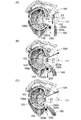
- a spiral 21 having a hollow structure is inserted into the body from the first portal 104, and the spiral 21 is passed through the notch 10 of the inclined portion 3 and screwed into the coracoid process 103, whereby the inclined portion 3 is formed by the spiral 21.
- the third step of fastening the screw to the coracoid process 103 is carried out (FIG. 5).
- the guide wire 22 inserted into the body from the first portal 104 is passed through the notch 10 and pierced into the coracoid process 103.
- the spiral 21 is moved toward the notch 10 along the guide wire 22, and the spiral 21 is passed through the notch 10 to pass the coracoid process 103.
- the guide wire 22 is then pulled out of the body from the first portal 104 (FIG. 5 (B) shows the state after the guide wire 22 is pulled out of the body).
- the spiral portion of the spiral 21 is passed through the notch 10 of the inclined portion 3 and screwed into the coracoid process 103, and is between the head of the spiral 21 and the coracoid process 103. By sandwiching the inclined portion 3, the inclined portion 3 is fastened to the coracoid process 103 by the spiral 21.
- the spiral 23 having a hollow structure from the first portal 104 (FIG. 5 (B). )) Is inserted into the body, the spiral 23 is passed through the through hole 12 of the inclined portion 3 and screwed into the coracoid process 103, so that the inclined portion 3 is fastened to the coracoid process 103 by the spiral 23. It is done.
- the guide wire 24 inserted into the body from the first portal 104 is passed through the through hole 12 and pierced into the coracoid process 103.
- the spiral 23 is moved toward the through hole 12 along the guide wire 24, and the spiral 23 is passed through the through hole 12 to pass the coracoid process 103.
- the guide wire 24 is then pulled out of the body from the first portal 104 (FIG. 5B shows a state immediately before the spiral 23 is passed through the through hole 12).
- the spiral portion of the spiral 23 is passed through the through hole 12 of the inclined portion 3 and screwed into the coracoid process 103, whereby the space between the head of the spiral 23 and the coracoid process 103 is performed.
- the inclined portion 3 is sandwiched between the two, and the inclined portion 3 is fastened to the coracoid process 103 by the spiral 23.
- the coracoid process 103 is attached to the coracoid process 103 with the joint tendon 109 by the bone flea 25 inserted from the first portal 104, and the coracoid process 103 is attached to the scapula 108.
- a fourth step of cutting from is carried out. At this time, the bone chisel 25 is inserted along the handle body 4 and the bone chisel 25 is inserted into the shoulder joint.
- the bone chisel 25 (the base end portion of the bone chisel 25) with a hammer while the bone chisel 25 is aligned with the handle body 4, the bone chisel 25 is slid along the handle body 4. , The coracoid process 103 is cut by the bone chisel 25.
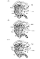
- FIGS. 7 (A), 7 (B), and 7 (C) by moving the surgical instrument 1 downward, the coracoid process 103 with the joint tendon 109 is moved downward. Then, the fifth step of inserting the coracoid process 103 into the incision 102 of the subscapularis muscle 100 and bringing it close to the scapular neck 108a is performed. At this time, the neurovascular system 200 in the vicinity of the shoulder joint also moves downward by pressing the joint tendon 109 or the coracoid process 103 that moves downward.
- the neurovascular system 200 includes a myocutaneous nerve 200a, an axillary nerve 200b, and a subclavian artery 200c, and FIG. 7 shows the myocutaneous nerve 200a, the axillary nerve 200b, and the subclavian artery by pressing the joint tendon 109. It shows a state in which the artery 200c moves downward.
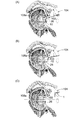
- a sixth step is performed in which a spiral 26 having a hollow structure is inserted into the body from the second portal 111, passed through the notch 10, and screwed into the coracoid process 103 and the scapula neck 108a (FIG. 8). ..
- the guide wire 27 inserted into the body from the second portal 111 is passed through the cavity of the spiral 21 and pierced into the scapula neck 108a.
- FIG. 8 shows the state when the spiral 21 is heading toward the second portal 111 along the guide wire 27, and FIGS. 8B and 8C show the spiral 21 taken out of the body. Shows the later state).
- the spiral 26 is moved toward the notch 10 along the guide wire 27, and the spiral 26 is passed through the notch 10 to pass the coracoid process.
- FIGS. 8A and 8B when the spiral 23 is screwed into the coracoid process 103, the spiral 23 is screwed into the coracoid process 103 in the sixth step. Is also released, and the spiral 23 is taken out of the body from the second portal 111.
- the guide wire 28 inserted into the body from the second portal 111 is passed through the cavity of the spiral 23 and pierced into the scapula neck 108a. Is done. After that, as shown in FIG.
- the spiral 23 is unscrewed into the coracoid process 103, and the spiral 23 is moved along the guide wire 28 to be moved from the second portal 111 to the outside of the body.
- the guide wire 28 is pulled out of the body from the second portal 111.
- the seventh step of removing the surgical instrument 1 from the spiral 26 and taking the surgical instrument 1 out of the body from the first portal 104 is performed.
- the surgical instrument 1 can be easily removed from the spiral 26 by having an opening in the notch 10 through which the spiral 26 is passed (that is, the spiral 26 has the notch 10 (bifurcated portions 11, 11).
- the surgical instrument 1 can be removed from the spiral 26 by performing a simple operation of moving the surgical instrument 1 so as to come out of the space).
- the coracoid process 103 is transplanted to the scapula neck 108a (the coracoid process 103 is fixed to the scapula neck 108a by the spiral 26).
- the guide wire 30 is inserted into the body from the second portal 111, and the hole of the coracoid process 103 into which the spiral 23 is screwed and the guide wire are inserted.
- the guide wire 30 (FIG. 10) is passed through the hole in the scapula neck 108a where 28 (FIG. 8) was pierced.
- the spiral 29 is moved along the guide wire 30 with the guide wire 30 passed through the cavity of the spiral 29, and the spiral 29 is formed into the above-mentioned coracoid process 103.
- the spirals 21 and 23 are screwed into the coracoid process 103
- the sixth step (FIG. 8) the screwing of the spirals 21 and 23 into the coracoid process 103 is released.
- the spirals 21 and 23 are taken out of the body, the spiral 26 is screwed into the coracoid process 103 and the scapula neck 108a in the sixth step (FIG. 8), and the spiral 29 is screwed into the coracoid process in the seventh step (FIG. 9). Screwing into the protrusion 103 and the scapula neck 108a can be achieved by using a known driver.
- the driver has, for example, a cavity through which a guide wire can be inserted, and by inserting the tip of the driver into the cavity of the spirals 21, 23, 26, 29, the tip of the driver has a spiral 21, 23, 26, It is possible to connect 29.
- the cavity of the driver is opened at the tip of the driver, and when the spirals 21, 23, 26, 29 are connected to the tip of the driver, the opening at the tip of the driver is the spiral 21, 23, 26.
- the spiral portion of the spiral is screwed into the coracoid process 103, or the spiral portion of the spiral is screwed into the coracoid process 103 and the scapula neck 108a. After that, by retracting the driver along the guide wire, the spiral is removed from the tip of the driver and the driver is taken out of the body.
- the driver when unscrewing the spirals 21 and 23 into the coracoid process 103 and taking out the spirals 21 and 23 outside the body, the driver is moved along the guide wire with the guide wire passed through the cavity of the driver. By inserting it into the body and inserting the tip of the driver into the cavity of the spiral, the spiral is connected to the tip of the driver. Then, by rotating the driver, the screwing of the spiral into the coracoid process 103 is released, and then, by retracting the driver and the spiral along the guide wire, the driver and the spiral are taken out of the body. ..
- the inclined portion 3 is inclined at an angle ⁇ (FIG. 2 (C)) of 95 ° or more and 115 ° or less with respect to the handle main body 4, which is shown in FIG.
- ⁇ FOG. 2 (C)
- the inclined portion 3 can be brought into contact with the coracoid process 103 under the condition that the handle 2 passes through the first portal 104 formed at a position directly above the coracoid process 103.
- the coracoid process 103 is stable because the coracoid process 103 is attached to the scapula 108 as shown in FIG.
- the spiral 21 can be passed through the notch 10 and screwed into the coracoid process 103. Therefore, the inclined portion 3 can be easily connected to the coracoid process 103 by using the spiral 21. Then, with the inclined portion 3 connected to the coracoid process 103 in this way, if the coracoid process 103 is cut from the scapula 108 as shown in FIG. 6, the surgical instrument 1 is moved downward as shown in FIG. The coracoid process 103 can be brought close to the scapular neck 108a by a simple operation. For the above reasons, according to the surgical instrument 1 of the present embodiment, the coracoid process 103 can be easily brought close to the scapula neck 108a.
- the joint tendon 109 and the coracoid process 103 are also moved downward.
- the neurovascular system 200 in the vicinity of the shoulder joint can be moved downward.
- the pinching of the neurovascular system 200 in the anterior-posterior direction (horizontal direction) by the subscapularis muscle 100 and the joint tendon 109 can be weakened, so that the neurovascular system 200 can be prevented from being damaged.
- the protruding portion 13 is formed at a position on the side of the through hole 12, the protruding portion 13 can be used as a mark for positioning the through hole 12. This makes it possible to easily arrange the through hole 12 at a desired position of the coracobrachial projection 103 in the second step (FIG. 4).
- a medical device set including the surgical instrument 1 shown in FIGS. 1 and 2 and the cutting tool 40 shown in FIG. 11 can be used.
- the cutting tool 40 can be used as a bone chisel 25 for cutting the coracoid process 103 in the fourth step shown in FIG.
- the cutting tool 40 (FIG. 11) is a series of a thick portion 41 used as a handle and a thin portion 42 having a thickness thinner than that of the thick portion 41.
- the tip 42a of the thin portion 42 farthest from the thick portion 41 is the thinnest cutting edge, and the length L4 of the thin portion 42 is 6 cm or more and 8 cm or less. If the cutting tool 40 is used as a bone chisel 25 (FIG. 6) for cutting the coracoid process 103, the length L4 (FIG.
- the handle body 4 can be suitably used as a guide for determining the cutting position of the coracoid process 103.
- the thin-walled portion 42 is formed so as to gradually widen and gradually become thinner as it is separated from the grip portion 5. Further, as shown in FIG. 11B, it is preferable that a warp is formed on the tip end side of the thin wall portion 42.
- the present invention does not require the use of the cutting tool 40, and a device other than the cutting tool 40 may be used as a bone chisel for cutting the coracoid process 103.
- the surgical instrument 1 shown in FIGS. 1 and 2 the first wire 50, the second wire 51, and the third wire 52 shown in FIG. 12 and FIG. 13
- a medical device set including the first sleeve 53 shown in the above can be used.
- the first wire 50, the second wire 51, the third wire 52, and the first sleeve 53 can be passed through the notch 10 and the through hole 12 of the surgical instrument 1, respectively.
- the first sleeve 53 shown in FIG. 13 is a hollow cylinder and is made of a stainless alloy, a titanium alloy, or an aluminum alloy.
- the outer diameter of the first sleeve 53 is, for example, 8 mm or less, and the inner diameter of the first sleeve 53 is, for example, 2 mm or less.
- the first sleeve 53 is used to guide the movement of the wires 50 and 51, and the wires 50, 51 and 52 can be inserted into the cavities of the first sleeve 53, respectively. ..
- the first wire 50 shown in FIG. 12A is a hollow tubular body and is formed of a stainless alloy, a titanium alloy, or an aluminum alloy.
- the outer diameter of the first wire 50 is, for example, 4 mm or less, and the inner diameter of the first wire 50 is, for example, 2 mm or less.
- a spirally extending groove 50a is formed on the outer peripheral surface of the tip of the first wire 50.
- the first wire 50 is used as, for example, the guide wires 22 and 24 shown in FIG. 5 and the guide wires 27 and 28 shown in FIG. 8 and is used as the first wire 50 (FIG. 12 (A)).
- the third wire 52 (FIG. 12 (C)) can be inserted through the cavity.
- the second wire 51 shown in FIG. 12B is formed of a stainless alloy, a titanium alloy, or an aluminum alloy, and the outer diameter of the second wire 51 is, for example, 2 mm or less. As shown in FIG. 14, the tip portion 51a of the second wire 51 has a rounded shape.
- the above-mentioned second wire 51 is used to guide the movement of the first sleeve 53.
- the second wire 51 can also be used as the guide wire 30 shown in FIG.
- the third wire 52 shown in FIG. 12C is made of a stainless alloy, a titanium alloy, or an aluminum alloy, and the outer diameter of the third wire 52 is, for example, 2 mm or less. As shown in FIG. 15, the tip portion 52a of the third wire 52 has a tapered shape with a corner.
- the third wire 52 is used to form a hole in the coracoid process 103 and the scapula neck 108a, and is formed in the coracoid process 103 and the scapula neck 108a by the third wire 52.
- the hole formed by the third wire 52 can be expanded in diameter to form a hole suitable for screwing the spiral.
- Work 1 Insert the second wire 51 (FIG. 12 (B)) from the first portal 104 (FIG. 5) into the body toward the coracoid process 103, and cut the tip of the second wire 51 into the notch of the inclined portion 3. Positioned at 10.
- Work 2 The first sleeve 53 is moved along the second wire 51 while the second wire 51 (FIG. 12 (B)) is passed through the cavity of the first sleeve 53 (FIG. 13). The sleeve 53 is inserted into the body and guided to the coracoid process 103, the tip of the first sleeve 53 is positioned at the notch 10, and then the second wire 51 is pulled out of the body from the first portal 104 (FIG. 5).
- the first wire 50 protruding from the tip of the first sleeve 53 is passed through the notch 10 and pierced into the coracoid process 103, thereby leading to the coracoid process 103.
- the hole of 103 is enlarged by the first wire 50 to form a hole suitable for screwing the spiral 21 into the coracoid process 103.
- Work 5 After the first sleeve 53 is pulled out of the body from the first portal 104 (FIG. 5), the spiral 21 is first placed in a state where the first wire 50 (corresponding to the guide wire 22) is passed through the cavity of the spiral 21.
- the following operations 6 to 10 are sequentially performed in order to realize a state in which the spiral 23 is passed through the through hole 12 of the inclined portion 3 and screwed into the coracoid process 103.
- Work 6 Insert the second wire 51 (FIG. 12 (B)) from the first portal 104 (FIG. 5) into the body toward the coracoid process 103, and insert the tip of the second wire 51 into the through hole of the inclined portion 3. Positioned at 12.
- Work 7 The first sleeve 53 is moved along the second wire 51 while the second wire 51 (FIG. 12 (B)) is passed through the cavity of the first sleeve 53 (FIG. 13). The sleeve 53 is inserted into the body and guided to the coracoid process 103, the tip of the first sleeve 53 is positioned in the through hole 12, and then the second wire 51 is pulled out of the body from the first portal 104 (FIG. 5).
- the first wire 50 protruding from the tip of the first sleeve 53 is passed through the through hole 12 and pierced into the coracoid process 103, thereby leading to the coracoid process 103.
- the hole of 103 is enlarged by the first wire 50 to form a hole suitable for screwing the spiral 23 into the coracoid process 103.
- Work 10 After pulling out the first sleeve 53 from the first portal 104 (FIG. 5), the first wire 50 (corresponding to the guide wire 24) is passed through the cavity of the spiral 23, and the spiral 23 is first placed.
- the spiral 23 is passed through the through hole 12 and screwed into the hole of the coracoid process 103 formed in the operation 9, and then the wires 50 and 52. Is pulled out of the body from the first portal 104.
- Work 11 The second wire 51 (FIG. 12 (B)) is inserted into the body from the second portal 111 (FIG. 8) toward the coracoid process 103, and the tip of the second wire 51 is spiraled 21 (FIG. 8 (FIG. 8). A) Position it in the cavity of).
- Work 12 The first sleeve 53 is moved along the second wire 51 while the second wire 51 (FIG. 12 (B)) is passed through the cavity of the first sleeve 53 (FIG. 13).
- the sleeve 53 is inserted into the body and guided to the coracoid process 103, the tip of the first sleeve 53 is positioned in the cavity of the spiral 21, and then the second wire 51 is pulled out of the body from the second portal 111 (FIG. 8). (Pull out the second wire 51 from the cavity of the first sleeve 53).
- Work 13 By passing the third wire 52 (FIG. 12 (C)) through the cavity of the first sleeve 53, the third wire 52 is inserted into the body and guided to the coracoid process 103, and from the tip of the first sleeve 53.
- the protruding third wire 52 is passed through the cavity of the spiral 21 (FIG.
- the first wire 50 (guide) is passed through the cavity of the first sleeve 53 while passing the first wire 50 (FIG. 12 (A)) through the cavity of the first wire 50 while passing the third wire 52. (Corresponding to the wire 27) is inserted into the body and guided to the coracoid process 103, and the first wire 50 protruding from the tip of the first sleeve 53 is passed through the cavity of the spiral 21 and pierced into the scapula neck 108a.
- the following operations 17 to 21 are sequentially performed in order to release the screwing of the spiral 23 into the coracoid process 103 and take out the spiral 23 from the body.
- Work 17 The second wire 51 (FIG. 12 (B)) is inserted into the body from the second portal 111 (FIG. 8) toward the coracoid process 103, and the tip of the second wire 51 is spiraled 23 (FIG. 8 (FIG. 8). A) Position it in the cavity of).
- Work 18 The first sleeve 53 is inserted into the body by moving the first sleeve 53 along the second wire 51 while passing the second wire 51 through the cavity of the first sleeve 53 (FIG. 13). The tip of the first sleeve 53 is positioned in the cavity of the spiral 23, and then the second wire 51 is pulled out of the body from the second portal 111 (FIG. 8) (the cavity of the first sleeve 53).
- the following operations 22 to 24 are sequentially performed in order to realize a state in which the spiral 29 is screwed into the coracoid process 103 and the scapula neck 108a.
- the second wire 51 (FIG. 12 (B)) is inserted into the body from the second portal 111 (FIG. 10) toward the coracoid process 103, and the spiral 23 (FIGS. 5 to 8) is screwed into the body.
- the second wire 51 is inserted into the hole of the coracoid process 103 and the hole of the scapula neck 108a formed in the work 20 (the hole of the scapula neck 108a in which the guide wire 28 shown in FIG. 8 is pierced). Pass through.
- Work 23 With the second wire 51 (corresponding to the guide wire 30) passed through the cavity of the spiral 29, the spiral 29 is moved along the second wire 51 toward the coracoid process 103, and the spiral 23 (FIG.
- the medical device set including surgical instrument 1 (FIGS. 1, 2), wires 50, 51, 52 (FIG. 12), and first sleeve 53 (FIG. 13), at work 3,8,13,19.
- the third wire 52 (FIG. 12 (C)) is passed through the cavity of the first sleeve 53 (FIG. 13), and in operations 4, 9, 14, 20 the first wire 50 (FIG. 12 (A)) is first.
- the wires 52 and 50 can be smoothly guided to the coracoid process 103 without damaging the inside of the body by the wires 52 and 50.
- the first sleeve 53 is smoothly guided to the coracoid process 103 by passing the second wire 51 (FIG. 12 (B)) through the cavity of the first sleeve 53 (FIG. 13). be able to.
- the tip portion 51a of the second wire 51 since the tip portion 51a of the second wire 51 has a rounded shape, the second wire 51 does not damage the inside of the body in the operations 1, 6, 11, 17, and 22. , The second wire 51 can be moved toward the coracoid process 103.
- the surface of the scapula neck 108a is polished before the fifth step (FIG. 7) of bringing the coracoid process closer to the scapula neck 108a to obtain the scapula.
- a flattening step may be performed to flatten the surface of the cervical portion 108a.
- the coracoid process 103 is attached to the scapula neck 108a so that the surface of the scapula neck 108a flattened in the flattening step and the surface of the coracoid process 103 are in contact with each other. Proximity is done.
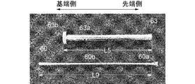
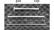
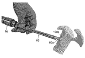
- the surgical instrument 1 shown in FIGS. 1 and 2 and the polishing shown in FIGS. 16 and 17 are performed.
- a medical device set including a fourth wire 66 and a fifth wire 67 may be used.
- the second sleeve 63, the third sleeve 64, the fourth sleeve 65, and the polishing tool 60 are hollow cylinders, respectively, and the third sleeve 64 can be inserted into the cavity of the second sleeve 63, or the third sleeve can be inserted. Inserting the fourth sleeve 65 into the cavity of 64, inserting the fourth wire 66 or the fifth wire 67 into the cavity of the fourth sleeve 65, and inserting the polishing tool 60 into the cavity of the second sleeve 63. Alternatively, the fourth wire 66 or the fifth wire 67 can be inserted into the cavity of the polishing tool 60. Further, the fifth wire 67 (FIG. 19 (B)) can be passed through the notch 10 and the through hole 12 (FIGS. 1 and 2) of the surgical instrument 1.
- the second sleeve 63 includes a second sleeve main body 63a having a constant inner diameter and outer diameter, and an annular flange 63b protruding from the outer surface of the base end of the second sleeve main body 63a in an annular shape.
- the third sleeve tip portion 64a and the third sleeve main body portion 64b are continuous in this order from the tip end side to the base end side (from the right side to the left side in FIG. 18). be.
- the length L6 of the third sleeve main body 64b is set to be equal to or greater than the length L5 of the second sleeve main body 63a
- the outer diameter of the third sleeve main body 64b is set to be equal to or smaller than the inner diameter of the second sleeve main body 63a.
- the outer diameter and inner diameter of the third sleeve tip portion 64a gradually decrease as it approaches the tip thereof.
- the fourth sleeve 65 has a fourth sleeve tip 65a, a fourth sleeve main body 65b, and a fourth sleeve base 65c from the tip side to the base end side (from the right side to the left side in FIG. 18). It is continuous in this order.
- the length L8 of the fourth sleeve main body 65b is set to be equal to or greater than the length L7 of the third sleeve 64, and the outer diameter of the fourth sleeve main body 65b is set to be equal to or less than the diameter of the tip opening of the third sleeve tip 64a. ..
- the outer diameter and inner diameter of the fourth sleeve tip portion 65a gradually decrease as it approaches the tip thereof.
- the outer diameter and inner diameter of the fourth sleeve base end portion 65c gradually decrease as it approaches the base end.
- the fourth sleeve 65 can also be used as the first sleeve 53 shown in FIG. 13 (in the illustrated example, the fourth sleeve 65 (FIGS. 16 and 18) and the first sleeve 53 (FIG. 13) are used. , It is supposed to have the same structure).
- the polishing tool tip 60a and the polishing tool main body 60b are continuous in this order from the tip side to the base end side (from the right side to the left side in FIG. 17).
- the length L9 of the polishing tool main body 60b is set to be equal to or longer than the length L5 of the second sleeve main body 63a.
- the outer diameter of the tip portion 60a of the polishing tool gradually increases as it approaches the tip thereof, and the outer diameter of the tip of the tip portion 60a of the polishing tool is set to be equal to or less than the inner diameter of the second sleeve main body portion 63a.
- the polishing tool 60 With the base end portion of the polishing tool 60 (base end portion of the polishing tool main body 60b) connected to the electric tool 70, the polishing tool 60 can be rotated around the central axis by operating the electric tool 70. It is possible. Further, by rotating the polishing tool 60 in a state where the tip surface of the polishing tool 60 (the tip surface of the tip portion 60a of the polishing tool) is in contact with the surface of the scapula neck 108a, the tip surface of the polishing tool 60 causes the scapula. It is possible to polish the surface of the neck 108a.
- the fourth wire 66 shown in FIG. 19A is a wire that can be inserted into the cavity of the polishing tool 60 and the cavity of the fourth sleeve 65.
- the fourth wire 66 is formed of a stainless alloy, a titanium alloy, or an aluminum alloy.
- the outer diameter of the fourth wire 66 is, for example, 2 mm or less, and the tip portion 66a of the fourth wire 66 is rounded. Shaped.
- the fourth wire 66 is used to guide the movement of the fourth sleeve 65.
- the fourth wire 66 can also be used as the second wire 51 shown in FIGS. 12 (B) and 14 (in the illustrated example, the fourth wire 66 (FIG. 19 (A)) and the second wire 51 (FIG. 19 (A)). It is assumed that 12 (B) and FIG. 14) have the same structure).
- the fifth wire 67 shown in FIG. 19B is a wire that can be inserted into the cavity of the polishing tool 60, the cavity of the fourth sleeve 65, and the notch 10 and the through hole 12 of the surgical instrument 1.
- the fifth wire 67 is formed of a stainless alloy, a titanium alloy, or an aluminum alloy, and the outer diameter of the fifth wire 67 is, for example, 2 mm or less.
- the tip portion 67a of the fifth wire 67 is tapered with a corner.
- the fifth wire 67 is used to pierce the coracoid process 103 and the scapula neck 108a.
- the fifth wire 67 can also be used as the third wire 52 shown in FIGS. 12 (C) and 15 (the fifth wire 67 (FIG. 19 (B)) and the third wire 52 (FIG. 12 (C)). , Fig. 15) has the same structure).
- the coracoid process 103 is brought close to the scapula neck 108a.
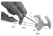
- the flattening step uses two fifth wires 67 (FIG. 19 (B)).
- the first fifth wire 67 is referred to as "fifth wire 67-1" and the second wire is described as “fifth wire 67-1”.
- the fifth wire 67 of the above is referred to as "fifth wire 67-2”.
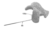
- Work 25 The fourth wire 66 (FIG. 19 (A)) is inserted into the body from the second portal 111 (FIG. 7) toward the scapula neck 108a, and the tip of the fourth wire 66 is inserted into the scapula neck 108a. (See FIG. 20).
- Work 26 As shown in FIG. 21, the fourth sleeve 65 is moved into the body by moving the fourth sleeve 65 along the fourth wire 66 while passing the fourth wire 66 through the cavity of the fourth sleeve 65. It is inserted into the scapula neck 108a, and then the fourth wire 66 is pulled out from the cavity of the fourth sleeve 65.
- Work 27 By passing the fifth wire 67-1 (FIG.
- the second sleeve 63 is moved along the third sleeve 64 while the third sleeve 64 is passed through the cavity of the second sleeve 63 (FIG. 18).
- the second sleeve 63 is inserted into the body and guided to the scapular neck 108a.
- Work 29 The third sleeve 64 and the fourth sleeve 65 are pulled out of the body from the second portal 111 (FIG. 7) so that only the fifth wire 67-1 has passed through the cavity of the second sleeve 63 (FIG. 7). 22 indicates a state after the work 29 has been performed).
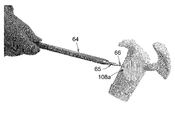
- Work 30 With the base end side of the polishing tool main body 60b (FIGS.
- Work 31 By rotating the polishing tool 60 by driving the electric tool 70, the surface of the scapula neck 108a is polished by the tip surface of the polishing tool tip 60a, and the surface of the scapula neck 108a is flattened. After that, the polishing tool 60 and the second sleeve 63 are pulled out of the body from the second portal 111 (FIG. 7).
- Work 32 The surgical instrument 1 is inserted into the body by moving the surgical instrument 1 along the fifth wire 67-1 while passing the fifth wire 67-1 through the notch 10 of the surgical instrument 1.
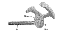
- Task 33 Insert the fourth wire 66 (FIG. 19 (A)) from the second portal 111 (FIG. 7) into the body toward the scapula neck 108a, and insert the tip 66a of the fourth wire 66 into the surgical instrument. It is passed through the through hole 12 of 1 and brought into contact with the surface of the scapula neck 108a.
- Work 34 The fourth sleeve 65 is inserted into the body by moving the fourth sleeve 65 along the fourth wire 66 while passing the fourth wire 66 through the cavity of the fourth sleeve 65 (FIG. 18). The fourth wire 66 is pulled out from the cavity of the fourth sleeve 65.
- Work 35 By passing the fifth wire 67-2 (FIG. 24, 19 (b)) through the cavity of the fourth sleeve 65, the fifth wire 67-2 is inserted into the body and guided to the scapula neck 108a.
- FIG. 24 shows a state in which the fifth wire 67-2 is passed through the through hole 12 and pierced into the scapula neck 108a.
- the fourth sleeve 65 is not shown. Yes).
- Work 36 After pulling out the fourth sleeve 65 and the fifth wire 67-2 from the second portal 111 (FIG. 7), the surgical instrument 1 is removed from the fifth wire 67-1 by moving the surgical instrument 1.
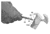
- the fourth sleeve 65 is moved along the fourth wire 66 to move the fourth sleeve 65.
- Work 39 The third sleeve 64 is inserted into the body by moving the third sleeve 64 along the fourth sleeve 65 while passing the fourth sleeve 65 through the cavity of the third sleeve 64 (FIG. 18).
- Guided to the scapula neck 108a see FIG. 27
- the second sleeve 63 is passed along the third sleeve 64 with the third sleeve 64 passed through the cavity of the second sleeve 63 (FIG. 18).
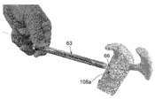
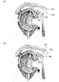
- the polishing tool 60 By passing the fourth wire 66 through the cavity of 60, the polishing tool 60 is inserted into the body and guided to the scapula neck 108a, and the tip of the polishing tool 60a is projected from the tip of the second sleeve 63. The tip surface of the tip portion 60a of the polishing tool is brought into contact with the surface of the scapula neck portion 108a (see FIG. 30).
- Work 42 By rotating the polishing tool 60 by driving the electric tool 70, the surface of the scapula neck 108a is polished by the tip surface of the polishing tool tip 60a, and the surface of the scapula neck 108a is flattened. Is done.
- the third sleeve 64 can be inserted into the body using the four sleeves 65 as a guide and the fourth sleeve 65 can be inserted into the body using the fourth wire 66 as a guide, the work of securing a space for passing the polishing tool 60 into the body can be smoothly advanced. be able to.
- the tip portion 65a of the fourth sleeve 65 and the tip portion 64a of the third sleeve 64 each exhibit a tapered shape (the fourth sleeve tip portion 65a and the third sleeve tip portion 64a are attached to these tips.
- the outer diameter gradually decreases as it approaches), so that the fourth sleeve 65 and the third sleeve 64 can be smoothly inserted into the body. From this point as well, the work of securing a space for passing the polishing tool 60 can be smoothly proceeded.
- the tip portion 66a of the fourth wire 66 (FIG. 19 (A)) has a rounded shape, the fourth wire 66 can be attached to the scapula in the work 25, 33, 37 without damaging the inside of the body. It can be moved towards the neck 108a.
- the guide wire 27 inserted into the body from the second portal 111 is inserted into the cavity of the spiral 21 and the shoulder formed by the operation 27.
- the guide wire 27 is pierced into the scapula neck 108a, and the guide wire 28 inserted into the body from the second portal 111 is formed by the cavity of the spiral 23 and the work 35. It is considered that the guide wire 28 is pierced into the scapula neck 108a by passing through the hole of the scapula neck 108a.
- the guide wire 30 inserted into the body from the second portal 111 is inserted into the hole of the coracoid process 103 into which the spiral 23 (FIGS. 5 to 8) is screwed, and the work 35. It is passed through the hole in the formed scapular neck 108a.
- Example of modification of work 31 By rotating the polishing tool 60 by driving the electric tool 70, the surface of the scapula neck 108a is polished by the tip surface of the polishing tool tip 60a, and the surface of the scapula neck 108a is formed. Flattening is performed, after which the polishing tool 60, the second sleeve 63, and the fifth wire 67-1 are pulled out of the body from the second portal 111 (FIG. 7).
- the guide wire 27 inserted into the body from the second portal 111 is inserted into the cavity of the spiral 21 and the hole of the scapula neck 108a formed by the work 27.
- the surface of the coracoid process 103 is surely in contact with the surface of the scapula neck 108a flattened in the flattening step.
- the coracoid process 103 can be fixed to the scapula neck 108a by the spiral 26 (FIGS. 8 to 10).
- the guide wire 22 (FIG. 5 (A)), the guide wire 24 (FIG. 5 (B)), the guide wire 27 (FIG. 8)), the guide wire 28 (FIG. 8), and the guide wire 30 (FIG. 8). It is not an essential condition to use 10 (A) and 10 (B).
- the spiral 21 is inserted into the body from the first portal 104, the spiral 21 is passed through the notch 10, and screwed into the coracoid process 103, or in the third step (FIG. 5).
- the spiral 23 is inserted into the body from the first portal 104, the spiral 23 is passed through the through hole 12 and screwed into the coracoid process 103, and in the sixth step (FIG. 8), the spiral 23 is screwed into the coracoid process 103.
- the unfilled spiral 21 is taken out of the body from the second portal 111, or the spiral 26 is inserted into the body from the second portal 111 in the sixth step (FIG. 8), and the spiral 26 is passed through the notch 10.
- the spiral 29 is inserted into the body from the second portal, and the spiral 29 is passed through the hole of the coracoid process 103 into which the spiral 23 is screwed to pass the coracoid process 103.
- screwing into the shoulder blade neck 108a may be performed by using a known means other than the guide wire.
- the spirals 21, 23, 26, 29 may not have a hollow structure (spirals 21, 23, 29). 26 and 29 may not have a cavity).
Landscapes
- Health & Medical Sciences (AREA)
- Life Sciences & Earth Sciences (AREA)
- Surgery (AREA)
- Orthopedic Medicine & Surgery (AREA)
- Medical Informatics (AREA)
- Engineering & Computer Science (AREA)
- Biomedical Technology (AREA)
- Heart & Thoracic Surgery (AREA)
- Nuclear Medicine, Radiotherapy & Molecular Imaging (AREA)
- Molecular Biology (AREA)
- Animal Behavior & Ethology (AREA)
- General Health & Medical Sciences (AREA)
- Public Health (AREA)
- Veterinary Medicine (AREA)
- Dentistry (AREA)
- Oral & Maxillofacial Surgery (AREA)
- Surgical Instruments (AREA)
Abstract
L'invention concerne un instrument chirurgical grâce auquel il est possible d'amener facilement une apophyse coracoïde à proximité de l'omoplate et du cou. Cet instrument chirurgical comprend un motif (2) qui s'étend dans une première direction, et une partie inclinée (3) qui s'étend dans une seconde direction à partir de l'extrémité distale du motif (2). La seconde direction dans laquelle la partie inclinée (3) s'étend est inclinée selon un angle α de 95-115 degrés (inclus) par rapport à la première direction dans laquelle s'étend le motif (2). Une encoche (10) dans laquelle passe une vis est formée dans le bord extérieur de la partie inclinée (3).
Priority Applications (4)
| Application Number | Priority Date | Filing Date | Title |
|---|---|---|---|
| EP21837211.8A EP4179984A4 (fr) | 2020-07-08 | 2021-07-06 | Instrument chirurgical, ensemble d'outils médicaux et procédé de déplacement |
| CN202180047058.XA CN115768366B (zh) | 2020-07-08 | 2021-07-06 | 手术器械、医疗器具组件以及移植方法 |
| US18/014,889 US12599420B2 (en) | 2020-07-08 | 2021-07-06 | Surgical instrument, medical tool set, and movement method |
| JP2022535360A JP7695717B2 (ja) | 2020-07-08 | 2021-07-06 | 手術器械、医療器具セット、及び移植方法 |
Applications Claiming Priority (2)
| Application Number | Priority Date | Filing Date | Title |
|---|---|---|---|
| JP2020-117520 | 2020-07-08 | ||
| JP2020117520 | 2020-07-08 |
Publications (1)
| Publication Number | Publication Date |
|---|---|
| WO2022009901A1 true WO2022009901A1 (fr) | 2022-01-13 |
Family
ID=79553202
Family Applications (1)
| Application Number | Title | Priority Date | Filing Date |
|---|---|---|---|
| PCT/JP2021/025519 Ceased WO2022009901A1 (fr) | 2020-07-08 | 2021-07-06 | Instrument chirurgical, ensemble d'outils médicaux et procédé de déplacement |
Country Status (5)
| Country | Link |
|---|---|
| US (1) | US12599420B2 (fr) |
| EP (1) | EP4179984A4 (fr) |
| JP (1) | JP7695717B2 (fr) |
| CN (1) | CN115768366B (fr) |
| WO (1) | WO2022009901A1 (fr) |
Citations (6)
| Publication number | Priority date | Publication date | Assignee | Title |
|---|---|---|---|---|
| JP2009545364A (ja) * | 2006-07-31 | 2009-12-24 | ティー.エー.ジー. メディカル プロダクツ ア リミテッド パートナーシップ | 関節鏡下骨移植法及びそれに有用な医療器具 |
| JP2013525012A (ja) * | 2010-04-30 | 2013-06-20 | スミス アンド ネフュー インコーポレーテッド | 不規則な形状の本体に穴をあけるためのガイド |
| US20150157462A1 (en) * | 2012-06-27 | 2015-06-11 | Steven Ek | Devices, apparatuses, kits, and methods for repair of articular surface and/or articular rim |
| JP2016513566A (ja) * | 2013-03-15 | 2016-05-16 | スミス アンド ネフュー インコーポレーテッドSmith & Nephew,Inc. | 外科手術用固定具 |
| JP2017119111A (ja) * | 2015-12-29 | 2017-07-06 | シンセス・ゲーエムベーハーSynthes GmbH | 外科処置のための骨準備の方法及びシステム |
| WO2019099451A2 (fr) * | 2017-11-14 | 2019-05-23 | Conmed Corporation | Fixation d'un greffon osseux à l'os glénoïde et modes de réalisation associés |
Family Cites Families (19)
| Publication number | Priority date | Publication date | Assignee | Title |
|---|---|---|---|---|
| US5342369A (en) * | 1992-09-11 | 1994-08-30 | The Board Of Regents Of The University Of Washington | System for repair of bankart lesions |
| US5820107A (en) * | 1996-03-26 | 1998-10-13 | Hall; Kessie M. | Multi-use lever |
| US5855358A (en) * | 1997-09-29 | 1999-01-05 | Witter; Lowell F. | Framework removal tool |
| US20040073229A1 (en) * | 2002-10-11 | 2004-04-15 | Lin-Min Yang | Thoracic spine posterior transpedicular screw finder |
| US7473267B2 (en) * | 2003-04-25 | 2009-01-06 | Warsaw Orthopedic, Inc. | System and method for minimally invasive posterior fixation |
| US7959564B2 (en) * | 2006-07-08 | 2011-06-14 | Stephen Ritland | Pedicle seeker and retractor, and methods of use |
| US7735806B2 (en) * | 2007-06-21 | 2010-06-15 | Scosche Industries, Inc. | Panel removal tool and method |
| EP2135562B1 (fr) * | 2008-06-20 | 2015-09-09 | Arthrex, Inc. | Plaque à profile en coin |
| DE602009000826D1 (de) | 2008-06-20 | 2011-04-21 | Arthrex Inc | Latarjet-Instrumentierung |
| US8303589B2 (en) * | 2008-06-24 | 2012-11-06 | Extremity Medical Llc | Fixation system, an intramedullary fixation assembly and method of use |
| USD631319S1 (en) * | 2009-10-15 | 2011-01-25 | Wade Davis | Stake puller |
| US9597188B2 (en) * | 2011-04-06 | 2017-03-21 | DePuy Synthes Products, Inc. | Version-replicating instrument and orthopaedic surgical procedure for using the same to implant a revision hip prosthesis |
| EP2779927B1 (fr) * | 2011-11-18 | 2018-10-03 | Synthes GmbH | Implant pour fracture du col du fémur |
| FR2996114B1 (fr) | 2012-10-02 | 2015-02-13 | Sem Sa | Guide de percage pour butee anterieure d'epaule |
| DE102014200187A1 (de) * | 2014-01-09 | 2015-07-09 | Intercus Gmbh | Instrument zur Plattenosteosynthese |
| CN104306059B (zh) | 2014-11-21 | 2016-09-14 | 陆晓生 | 一种肩胛骨喙突区记忆合金解剖锁定内固定的器械 |
| WO2016145152A1 (fr) | 2015-03-10 | 2016-09-15 | Smith & Nephew, Inc. | Latarjet ouvert pour la correction d'une perte osseuse glénoïdienne antérieure-inférieure |
| CN204765882U (zh) | 2015-09-13 | 2015-11-18 | 管廷进 | 喙突钢丝环绕器 |
| CN205386162U (zh) * | 2015-12-23 | 2016-07-20 | 常州华森医疗器械有限公司 | 喙锁韧带微创重建定位器 |
-
2021
- 2021-07-06 EP EP21837211.8A patent/EP4179984A4/fr active Pending
- 2021-07-06 JP JP2022535360A patent/JP7695717B2/ja active Active
- 2021-07-06 US US18/014,889 patent/US12599420B2/en active Active
- 2021-07-06 CN CN202180047058.XA patent/CN115768366B/zh active Active
- 2021-07-06 WO PCT/JP2021/025519 patent/WO2022009901A1/fr not_active Ceased
Patent Citations (6)
| Publication number | Priority date | Publication date | Assignee | Title |
|---|---|---|---|---|
| JP2009545364A (ja) * | 2006-07-31 | 2009-12-24 | ティー.エー.ジー. メディカル プロダクツ ア リミテッド パートナーシップ | 関節鏡下骨移植法及びそれに有用な医療器具 |
| JP2013525012A (ja) * | 2010-04-30 | 2013-06-20 | スミス アンド ネフュー インコーポレーテッド | 不規則な形状の本体に穴をあけるためのガイド |
| US20150157462A1 (en) * | 2012-06-27 | 2015-06-11 | Steven Ek | Devices, apparatuses, kits, and methods for repair of articular surface and/or articular rim |
| JP2016513566A (ja) * | 2013-03-15 | 2016-05-16 | スミス アンド ネフュー インコーポレーテッドSmith & Nephew,Inc. | 外科手術用固定具 |
| JP2017119111A (ja) * | 2015-12-29 | 2017-07-06 | シンセス・ゲーエムベーハーSynthes GmbH | 外科処置のための骨準備の方法及びシステム |
| WO2019099451A2 (fr) * | 2017-11-14 | 2019-05-23 | Conmed Corporation | Fixation d'un greffon osseux à l'os glénoïde et modes de réalisation associés |
Non-Patent Citations (2)
| Title |
|---|
| LAFFOSSE LLEJEUNE EBOURCHARD A ET AL.: "The arthroscopic Latarjet procedure for the treatment of anterior shoulder instability. Arthroscopy: The Journal of Arthroscopy", RELATED SURGERY, vol. 23, no. 11, November 2007 (2007-11-01), pages 1242 - 12425 |
| See also references of EP4179984A4 |
Also Published As
| Publication number | Publication date |
|---|---|
| US20230301697A1 (en) | 2023-09-28 |
| US12599420B2 (en) | 2026-04-14 |
| CN115768366A (zh) | 2023-03-07 |
| EP4179984A4 (fr) | 2024-07-10 |
| EP4179984A1 (fr) | 2023-05-17 |
| CN115768366B (zh) | 2025-11-28 |
| JPWO2022009901A1 (fr) | 2022-01-13 |
| JP7695717B2 (ja) | 2025-06-19 |
Similar Documents
| Publication | Publication Date | Title |
|---|---|---|
| US11559296B2 (en) | Medical apparatus and method for attaching a suture to a bone | |
| AU761693B2 (en) | A surgical forceps | |
| US8551123B2 (en) | Device for the intraosteal seizing of sutures | |
| US20100318139A1 (en) | Method and apparatus for arthroscopic rotator cuff repair using transosseous tunnels | |
| US20090082788A1 (en) | Suture management method and apparatus | |
| US20110106124A1 (en) | Method and apparatus for arthroscopic rotator cuff repair using transosseous tunnels | |
| US20060293691A1 (en) | Apparatus and methods for performing cerclage | |
| CN101160100A (zh) | 钳子及使用所述钳子的系统 | |
| CN102946814A (zh) | 用于钻削不规则形状主体的钻头引导器 | |
| US20030018340A1 (en) | Method and apparatus for installing cannula | |
| JP5306900B2 (ja) | 靱帯再建術用骨片付き移植腱固定具 | |
| WO2016103366A1 (fr) | Instrument chirurgical pour effectuer des incisions | |
| EP2861159B1 (fr) | Appareil chirurgical endoscopique | |
| WO2022009901A1 (fr) | Instrument chirurgical, ensemble d'outils médicaux et procédé de déplacement | |
| CN117958938A (zh) | 一种髌骨横形骨折微创手术固定套件及使用方法 | |
| CN109009334B (zh) | 一种骨科手术剥离导向装置 | |
| US20090157098A1 (en) | Surgical wire closure devices | |
| CN114699159A (zh) | 关节镜辅助治疗前后交叉韧带撕脱骨折的临时固定系统 | |
| JP6522562B2 (ja) | 外科用治具及び外科用骨固定ユニット | |
| CN217186307U (zh) | 钻孔导向器及手术钻孔装置 | |
| CN209332199U (zh) | 一种膝关节镜手术剥离导向装置 | |
| WO2022077004A1 (fr) | Instrument chirurgical arthroscopique permettant de manipuler un tissu osseux | |
| US20050222600A1 (en) | Inverted capsular punch and arthroscopic method | |
| CN110811717A (zh) | 一种便于一步法置入的铆钉组件及铆钉一步法置入方法 | |
| JP2006175216A (ja) | 縫合支援器具 |
Legal Events
| Date | Code | Title | Description |
|---|---|---|---|
| 121 | Ep: the epo has been informed by wipo that ep was designated in this application |
Ref document number: 21837211 Country of ref document: EP Kind code of ref document: A1 |
|
| ENP | Entry into the national phase |
Ref document number: 2022535360 Country of ref document: JP Kind code of ref document: A |
|
| NENP | Non-entry into the national phase |
Ref country code: DE |
|
| ENP | Entry into the national phase |
Ref document number: 2021837211 Country of ref document: EP Effective date: 20230208 |