WO2022014096A1 - 電解質分析装置 - Google Patents
電解質分析装置 Download PDFInfo
- Publication number
- WO2022014096A1 WO2022014096A1 PCT/JP2021/009801 JP2021009801W WO2022014096A1 WO 2022014096 A1 WO2022014096 A1 WO 2022014096A1 JP 2021009801 W JP2021009801 W JP 2021009801W WO 2022014096 A1 WO2022014096 A1 WO 2022014096A1
- Authority
- WO
- WIPO (PCT)
- Prior art keywords
- analysis
- electrolyte
- tank
- sample
- measurement
- Prior art date
- Legal status (The legal status is an assumption and is not a legal conclusion. Google has not performed a legal analysis and makes no representation as to the accuracy of the status listed.)
- Ceased
Links
Images


Classifications
-
- G—PHYSICS
- G01—MEASURING; TESTING
- G01N—INVESTIGATING OR ANALYSING MATERIALS BY DETERMINING THEIR CHEMICAL OR PHYSICAL PROPERTIES
- G01N35/00—Automatic analysis not limited to methods or materials provided for in any single one of groups G01N1/00 - G01N33/00; Handling materials therefor
- G01N35/00584—Control arrangements for automatic analysers
- G01N35/0092—Scheduling
-
- G—PHYSICS
- G01—MEASURING; TESTING
- G01N—INVESTIGATING OR ANALYSING MATERIALS BY DETERMINING THEIR CHEMICAL OR PHYSICAL PROPERTIES
- G01N35/00—Automatic analysis not limited to methods or materials provided for in any single one of groups G01N1/00 - G01N33/00; Handling materials therefor
- G01N35/00584—Control arrangements for automatic analysers
- G01N35/00722—Communications; Identification
- G01N35/00732—Identification of carriers, materials or components in automatic analysers
-
- G—PHYSICS
- G01—MEASURING; TESTING
- G01N—INVESTIGATING OR ANALYSING MATERIALS BY DETERMINING THEIR CHEMICAL OR PHYSICAL PROPERTIES
- G01N35/00—Automatic analysis not limited to methods or materials provided for in any single one of groups G01N1/00 - G01N33/00; Handling materials therefor
- G01N35/02—Automatic analysis not limited to methods or materials provided for in any single one of groups G01N1/00 - G01N33/00; Handling materials therefor using a plurality of sample containers moved by a conveyor system past one or more treatment or analysis stations
- G01N35/04—Details of the conveyor system
-
- G—PHYSICS
- G01—MEASURING; TESTING
- G01N—INVESTIGATING OR ANALYSING MATERIALS BY DETERMINING THEIR CHEMICAL OR PHYSICAL PROPERTIES
- G01N35/00—Automatic analysis not limited to methods or materials provided for in any single one of groups G01N1/00 - G01N33/00; Handling materials therefor
- G01N35/10—Devices for transferring samples or any liquids to, in, or from, the analysis apparatus, e.g. suction devices, injection devices
- G01N35/1002—Reagent dispensers
-
- G—PHYSICS
- G16—INFORMATION AND COMMUNICATION TECHNOLOGY [ICT] SPECIALLY ADAPTED FOR SPECIFIC APPLICATION FIELDS
- G16H—HEALTHCARE INFORMATICS, i.e. INFORMATION AND COMMUNICATION TECHNOLOGY [ICT] SPECIALLY ADAPTED FOR THE HANDLING OR PROCESSING OF MEDICAL OR HEALTHCARE DATA
- G16H10/00—ICT specially adapted for the handling or processing of patient-related medical or healthcare data
- G16H10/40—ICT specially adapted for the handling or processing of patient-related medical or healthcare data for data related to laboratory analysis, e.g. patient specimen analysis
-
- G—PHYSICS
- G01—MEASURING; TESTING
- G01N—INVESTIGATING OR ANALYSING MATERIALS BY DETERMINING THEIR CHEMICAL OR PHYSICAL PROPERTIES
- G01N35/00—Automatic analysis not limited to methods or materials provided for in any single one of groups G01N1/00 - G01N33/00; Handling materials therefor
- G01N2035/00178—Special arrangements of analysers
- G01N2035/00326—Analysers with modular structure
-
- G—PHYSICS
- G01—MEASURING; TESTING
- G01N—INVESTIGATING OR ANALYSING MATERIALS BY DETERMINING THEIR CHEMICAL OR PHYSICAL PROPERTIES
- G01N35/00—Automatic analysis not limited to methods or materials provided for in any single one of groups G01N1/00 - G01N33/00; Handling materials therefor
- G01N35/00584—Control arrangements for automatic analysers
- G01N35/00722—Communications; Identification
- G01N2035/00891—Displaying information to the operator
-
- G—PHYSICS
- G01—MEASURING; TESTING
- G01N—INVESTIGATING OR ANALYSING MATERIALS BY DETERMINING THEIR CHEMICAL OR PHYSICAL PROPERTIES
- G01N35/00—Automatic analysis not limited to methods or materials provided for in any single one of groups G01N1/00 - G01N33/00; Handling materials therefor
- G01N35/00584—Control arrangements for automatic analysers
- G01N35/0092—Scheduling
- G01N2035/0094—Scheduling optimisation; experiment design
-
- G—PHYSICS
- G01—MEASURING; TESTING
- G01N—INVESTIGATING OR ANALYSING MATERIALS BY DETERMINING THEIR CHEMICAL OR PHYSICAL PROPERTIES
- G01N35/00—Automatic analysis not limited to methods or materials provided for in any single one of groups G01N1/00 - G01N33/00; Handling materials therefor
- G01N35/02—Automatic analysis not limited to methods or materials provided for in any single one of groups G01N1/00 - G01N33/00; Handling materials therefor using a plurality of sample containers moved by a conveyor system past one or more treatment or analysis stations
- G01N35/04—Details of the conveyor system
- G01N2035/046—General conveyor features
- G01N2035/0462—Buffers [FIFO] or stacks [LIFO] for holding carriers between operations
-
- G—PHYSICS
- G01—MEASURING; TESTING
- G01N—INVESTIGATING OR ANALYSING MATERIALS BY DETERMINING THEIR CHEMICAL OR PHYSICAL PROPERTIES
- G01N27/00—Investigating or analysing materials by the use of electric, electrochemical, or magnetic means
- G01N27/26—Investigating or analysing materials by the use of electric, electrochemical, or magnetic means by investigating electrochemical variables; by using electrolysis or electrophoresis
- G01N27/28—Electrolytic cell components
- G01N27/30—Electrodes, e.g. test electrodes; Half-cells
- G01N27/333—Ion-selective electrodes or membranes
-
- G—PHYSICS
- G01—MEASURING; TESTING
- G01N—INVESTIGATING OR ANALYSING MATERIALS BY DETERMINING THEIR CHEMICAL OR PHYSICAL PROPERTIES
- G01N27/00—Investigating or analysing materials by the use of electric, electrochemical, or magnetic means
- G01N27/26—Investigating or analysing materials by the use of electric, electrochemical, or magnetic means by investigating electrochemical variables; by using electrolysis or electrophoresis
- G01N27/416—Systems
- G01N27/4166—Systems measuring a particular property of an electrolyte
-
- G—PHYSICS
- G01—MEASURING; TESTING
- G01N—INVESTIGATING OR ANALYSING MATERIALS BY DETERMINING THEIR CHEMICAL OR PHYSICAL PROPERTIES
- G01N33/00—Investigating or analysing materials by specific methods not covered by groups G01N1/00 - G01N31/00
- G01N33/48—Biological material, e.g. blood, urine; Haemocytometers
- G01N33/483—Physical analysis of biological material
- G01N33/487—Physical analysis of biological material of liquid biological material
- G01N33/49—Blood
- G01N33/4905—Determining clotting time of blood
-
- G—PHYSICS
- G01—MEASURING; TESTING
- G01N—INVESTIGATING OR ANALYSING MATERIALS BY DETERMINING THEIR CHEMICAL OR PHYSICAL PROPERTIES
- G01N33/00—Investigating or analysing materials by specific methods not covered by groups G01N1/00 - G01N31/00
- G01N33/48—Biological material, e.g. blood, urine; Haemocytometers
- G01N33/483—Physical analysis of biological material
- G01N33/487—Physical analysis of biological material of liquid biological material
- G01N33/49—Blood
- G01N33/492—Determining multiple analytes
Definitions
- the present invention relates to an electrolyte analyzer.
- Patent Document 1 describes a standard using an electrode portion.
- a measuring unit that measures the electromotive force of each solution and sample solution
- a diluting tank that dilutes the sample solution with a diluting solution to generate a sample solution
- a sample supply means that supplies the sample solution to the diluting tank, and diluting the diluted solution.
- a diluent supply means for supplying a tank, a standard solution supply means for supplying a standard solution to a dilution tank, a measurement solution supply means for supplying a standard solution and a sample solution from a dilution tank to an electrode portion, a standard solution and a sample solution. It is described that the diluting tank is provided with a control unit for controlling the supply of the diluted solution from the diluting tank to the electrode unit alternately and controlling the supply of the diluted solution to the diluting tank in a predetermined amount before producing the sample solution. Has been done.
- the electrolyte analyzer as described in Patent Document 1 described above is a specific electrolyte (sodium (Na), potassium (K), chlorine (Cl), etc.) contained in an electrolyte solution such as human blood and urine. It is a device that measures the concentration, and measures the concentration using an ion-selective electrode.
- a sample solution obtained by directly diluting serum as an electrolyte solution or diluted with a diluted solution is supplied to an ion selection electrode, and the liquid potential with the comparative electrode solution is measured.
- a standard solution is supplied to the ion-selective electrode, the liquid potential with the comparative electrode solution is measured in the same manner, and the electrolyte concentration of the sample solution is calculated from the two liquid potential levels.
- the flow type is mainly used.
- ion-selective electrodes are used as consumables in addition to reagents such as diluent, standard solution, and comparative electrode solution, and the replacement work of these consumables is performed by the user.
- the present invention has been made in view of such a problem, and provides an electrolyte analyzer capable of appropriately exchanging consumables while exerting an analysis processing capacity as compared with the conventional one.
- the present invention includes a plurality of means for solving the above problems, and one example thereof is an electrolyte analyzer for analyzing the electrolyte concentration of a sample, which is a consumable item for measuring the electrolyte concentration of the sample.
- the consumables of the plurality of analysis tanks are provided with a plurality of analysis tanks having a plurality of analysis tanks and a control unit for controlling the operation in the electrolyte analyzer including the analysis tanks, and the consumables of the plurality of analysis tanks analyze the same analysis item.
- the control unit is characterized in that an analysis tank to be used for measurement is selected from the plurality of analysis tanks according to the remaining measurable number of each of the plurality of consumables and the measurement request status.
- FIG. 1 The figure which shows the whole structure of the electrolyte analyzer of Example 1 of this invention.
- FIG. 1 The figure which shows the screen which selects the analysis tank to be preferentially used, which is displayed on the display apparatus of the electrolyte analyzer of Example 1.
- FIG. 2 The figure which shows the whole structure of the electrolyte analyzer of Example 2 of this invention.
- FIG. 2 The figure which shows the screen which selects the analysis tank to be preferentially used, which is displayed on the display apparatus of the electrolyte analyzer of Example 2.
- FIG. 1 The figure which shows the screen which selects the analysis tank to be preferentially used, which is displayed on the display apparatus of the electrolyte analyzer of Example 2.
- the electrolyte analyzer will be described when the device for analyzing the electrolyte item is composed of one or more devices, but the device configuration is not limited to these forms, and the automatic analyzer can be used. It can be installed.
- the automatic analyzer include a biochemical automatic analyzer and an immunological automatic analyzer. Alternatively, it is installed in a mass analyzer used for clinical examinations, a coagulation analyzer that measures the coagulation time of blood, a combined system of these with an automated biochemical analyzer, an automated immunoanalyzer, and an automated analysis system that applies these. Can be done.
- Example 1 The electrolyte analyzer of Example 1 of the present invention will be described with reference to FIGS. 1 to 7.
- FIG. 1 is a diagram showing the overall configuration of the electrolyte analyzer of the first embodiment
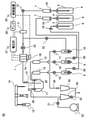
- FIG. 2 is a diagram showing a schematic configuration of an analysis tank in the electrolyte analyzer.
- the electrolyte analyzer 100 shown in FIG. 2 includes a transfer line 71, a gripper 55, a dispensing line 65, 66, a pre-analysis buffer 61, a post-analysis buffer 62, two analysis tanks 50, a sample probe 14, a display device 80, and a control device. It is equipped with 29 and so on.
- the transfer line 71 is installed at the end of the device, and transfers the transfer container 90, which carries a plurality of sample containers 15 for accommodating samples, loaded from the sample rack loading section (not shown) to the transfer position by the gripper 55. It is a device for carrying out and carrying out the transport container 90 for which measurement has been completed.
- sample containers 15 are mounted on the transport container 90 in this embodiment, it is sufficient that one or more sample containers 15 can be mounted on the transport container 90.
- the transport container 90 there is a sample holder or the like on which one sample container 15 can be mounted.
- the gripper 55 is a mechanism for transferring the transport container 90 from the transport line 71 to the dispensing lines 65 and 66, or from the dispensing lines 65 and 66 to the transport line 71.
- the dispensing lines 65 and 66 transport the sample container 15 to be dispensed to the dispensing position by the sample probe 14, or analyze the transport container 90 containing the sample container 15 after dispensing and buffer it. It is a mechanism for transporting up to 62.
- the pre-analysis buffer 61 and the post-analysis buffer 62 are spaces for waiting for the sample container 15 waiting to be dispensed into the analysis tank 50 and the sample container 15 after the analysis operation is completed until they are transported to another place.
- the analysis tank 50 is an analysis unit having an ISE electrode 1 for measuring the concentration of the electrolyte of the sample, and is provided with two, and shares a sample probe 14 for dispensing the sample into the analysis tank 50. The details will be described with reference to FIG.
- the number of analysis tanks 50 provided in the electrolyte analyzer 100 may be 2 or more, and may be 3 or more.
- the analysis tank 50 shown in FIG. 2 is a flow type using an ion selection electrode (hereinafter referred to as an ISE electrode (Ion Selective Electrode)).
- an ion selection electrode hereinafter referred to as an ISE electrode (Ion Selective Electrode)
- FIG. 2 the five mechanisms of the sample dispensing section, the ISE electrode section, the reagent section, the mechanism section, and the waste liquid mechanism are controlled as the main mechanisms of the analysis tank 50, and the electrolyte concentration is calculated from the measurement results.
- a control device 29 that executes display control is shown.
- the sample dispensing section includes the sample probe 14.
- a sample such as a patient sample held in the sample container 15 is dispensed by the sample probe 14 and drawn into the analyzer.
- the sample is a general term for an analysis target collected from a patient's living body, and is, for example, blood or urine.
- An analysis target to which a predetermined pretreatment is performed on these is also called a sample.
- the ISE electrode portion includes a dilution tank 11, a sipper nozzle 13, a diluent nozzle 24, an internal standard liquid nozzle 25, an ISE electrode 1, a comparison electrode 2, a pinch valve 23, a voltmeter 27, and an amplifier 28.
- the sample dispensed in the sample dispensing section is discharged to the diluting tank 11, and is diluted and stirred with the diluting liquid discharged from the diluting liquid nozzle 24 into the diluting tank 11.
- the shipper nozzle 13 is connected to the ISE electrode 1 by a flow path, and the diluted sample solution sucked from the diluting tank 11 is sent to the ISE electrode 1 by the flow path.
- the comparative electrode liquid contained in the comparative electrode liquid bottle 5 is sent to the comparative electrode 2 by operating the sipper syringe 10 with the pinch valve 23 closed.
- the diluted sample solution sent to the ISE electrode flow path and the comparison electrode solution sent to the comparison electrode flow path come into contact with each other, so that the ISE electrode 1 and the comparison electrode 2 are electrically conductive.
- the ISE electrode portion measures the concentration of a specific electrolyte contained in the sample by the potential difference between the ISE electrode 1 and the comparison electrode 2.
- the ISE electrode 1 has an electromotive force depending on the concentration of specific ions (for example, sodium ion (Na + ), potassium ion (K + ), chlor ion (Cl ⁇ ), etc.) in the sample solution.
- specific ions for example, sodium ion (Na + ), potassium ion (K + ), chlor ion (Cl ⁇ ), etc.
- An ion-sensitive film having a changing property is attached, and the ISE electrode 1 outputs an electromotive force according to each ion concentration in the sample solution. Gets the electromotive force between and.
- the control device 29 calculates and displays the ion concentration in the sample from the acquired electromotive force for each ion.
- the sample solution remaining in the dilution tank 11 is discharged by the waste liquid mechanism.
- the ISE electrode 1 is provided with an identification medium 1A for performing individual identification, and the ISE electrode portion includes a reading device 1B for reading the individual identification information recorded on the identification medium 1A. Is done. The identification information read by the reading device 1B is sent to the control device 29.
- the ISE electrodes 1 of the two analysis tanks 50 are provided to analyze the same analysis items, and have the same specifications.
- the potential difference between the ISE electrode 1 and the comparison electrode 2 has a characteristic of being easily affected by temperature changes and the like.
- the internal standard liquid is discharged from the internal standard liquid nozzle 25 into the diluting tank 11 between the measurement of one sample and the measurement of the next sample, and described above.
- the measurement is performed in the same manner as in the case of the sample of. It is preferable to make corrections according to the amount of fluctuation by using the results of internal standard solution measurement performed during sample measurement. In this case, the internal standard solution is not diluted.
- the reagent unit includes a suction nozzle 6 for sucking the reagent from the reagent container, a degassing mechanism 7, and a filter 16, and supplies reagents necessary for measurement.
- a suction nozzle 6 for sucking the reagent from the reagent container
- a degassing mechanism 7, and a filter 16 supplies reagents necessary for measurement.
- three types of reagents, an internal standard solution, a diluted solution, and a comparative electrode solution are used, and an internal standard solution bottle 3 containing the internal standard solution and a diluted solution bottle 4 containing the diluted solution are used.
- the comparative electrode liquid bottle 5 containing the comparative electrode liquid is set in the reagent section.
- FIG. 2 shows this state. Further, when cleaning the device, a cleaning liquid bottle for storing the cleaning liquid is set in the reagent unit.
- the internal standard liquid bottle 3 and the diluting liquid bottle 4 are connected to the internal standard liquid nozzle 25 and the diluting liquid nozzle 24 through a flow path, respectively, and each nozzle is installed in the diluting tank 11 with the tip introduced into the diluting tank 11. ing.
- the comparative electrode liquid bottle 5 is connected to the comparative electrode 2 through a flow path via the filter 16.
- a degassing mechanism 7 is connected to the flow path between the diluent bottle 4 and the dilution tank 11 and the flow path between the comparison electrode liquid bottle 5 and the comparison electrode 2, respectively, in the dilution tank 11 and in the flow path.
- the degassed reagent is supplied into the comparative electrode 2.
- the two analysis tanks 50 describe a form in which reagents are supplied from the dedicated internal standard liquid bottle 3, the diluent liquid bottle 4, and the comparative electrode liquid bottle 5, respectively. It can be in a shared form.
- the mechanism includes an internal standard solution syringe 8, a diluent syringe 9, a shipper syringe 10, solenoid valves 17, 18, 19, 20, 21, 22, 30, and preheat 12, and liquid transfer within or between each mechanism. It is responsible for such operations.
- the internal standard solution and the diluted solution are sent to the diluting tank 11 by the operation of the internal standard solution syringe 8 and the diluted solution syringe 9, and the solenoid valve provided in the flow path, respectively.
- the preheat 12 suppresses the influence of the temperature on the ISE electrode 1 by controlling the temperature of the internal standard solution and the diluted solution reaching the ISE electrode 1 within a certain range.
- the waste liquid mechanism includes a first waste liquid nozzle 26, a second waste liquid nozzle 36, a vacuum bin 34, a waste liquid receiver 35, a vacuum pump 33, and electromagnetic valves 31, 32, and the sample solution and the ISE electrode portion remaining in the dilution tank 11.
- the reaction solution remaining in the flow path of the above is discharged.
- the display device 80 is a part on which various screens such as an operation screen for ordering measurement items to be measured for a sample to be measured, a screen for confirming the measurement result, and the like are displayed, such as a liquid crystal display. Consists of. In particular, the remaining measurable number management screen 501 and the analysis tank selection screens 600 and 700 shown in FIG. 4 and the like are displayed. The details will be described later.
- It does not have to be a liquid crystal display, and may be replaced with a printer, etc., and can be configured with a display and a printer, etc., and various parameters, settings, measurement results, and measurements can be obtained based on the displayed operation screen. It can be a touch panel type display for inputting request information, analysis start / stop instructions, and the like.
- the control device 29 is connected to the analysis tank 50 and the like by a wired or wireless network line, and controls the operation in the electrolyte analyzer 100 including the analysis tank 50. Further, the control device 29 performs an operation using the potential of the ISE electrode 1 measured for the sample solution, and calculates the electrolyte concentration in the sample. At this time, more accurate measurement of the electrolyte concentration can be performed by calibrating the internal standard solution based on the measured ISE electrode potential.
- the control device 29 can be configured as a computer equipped with a CPU (Central Processing Unit), a RAM (Random Access Memory), a storage device, and an I / O port, and the RAM, the storage device, and the I / O port are via an internal bus. It is configured so that data can be exchanged with the CPU.
- the I / O port is connected to each of the above-mentioned mechanisms and controls their operation. The operation control is performed by reading the program stored in the storage device into the RAM and executing it by the CPU. Further, an input / output device is connected to the control device 29, so that input from the user and display of measurement results are possible.
- the measurement operation is controlled by the control device 29.
- the sample dispensed from the sample container 15 by the sample probe 14 of the sample dispensing portion is discharged to the dilution tank 11 of the ISE electrode portion.
- the diluting liquid is discharged from the diluting liquid bottle 4 from the diluting liquid nozzle 24 by the operation of the diluting liquid syringe 9, and the sample is diluted.
- the degassing treatment is performed by the degassing mechanism 7 installed in the middle of the diluted solution flow path.
- the diluted sample solution is sucked into the ISE electrode 1 by the operation of the shipper syringe 10 and the solenoid valve 22.
- the comparison electrode liquid is sent from the comparison electrode liquid bottle 5 into the comparison electrode 2 by the pinch valve 23 and the shipper syringe 10.
- the comparative electrode solution is, for example, an aqueous solution of potassium chloride (KCl) having a predetermined concentration, and when the sample solution and the comparative electrode solution come into contact with each other, the ISE electrode 1 and the comparative electrode 2 are electrically conductive.
- the electrolyte concentration of the comparative electrode solution is preferably high because it suppresses the influence of concentration fluctuations during sample feeding, but it may crystallize near the saturation concentration and cause clogging of the flow path. Therefore, it is desirable that the concentration is between 0.5 mmol / L and 3.0 mmol / L.
- the ISE electrode potential based on the comparative electrode potential is measured using the voltmeter 27 and the amplifier 28.
- the internal standard solution of the internal standard solution bottle 3 set in the reagent section is discharged to the dilution tank 11 by the internal standard solution syringe 8, and the electrolyte concentration of the internal standard solution is measured in the same manner as the sample measurement. ..
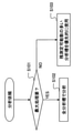
- FIGS. 3 to 7. are a flow for determining the request status and processing capacity
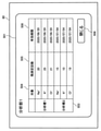
- FIG. 4 is a diagram showing a screen for managing the remaining measurable number displayed on the display device
- FIGS. 6 and 7 are priorities displayed on the display device. It is a figure which shows the screen which selects the analysis tank used for.
- the control device 29 measures the residual amount of each of the ISE electrodes 1 of the two analysis tanks 50.
- the analysis tank 50 on the side used for measurement is selected from the two analysis tanks 50 according to the possible number and the measurement request status.
- step S203 of FIG. 6, which will be described later, is a step of "determining whether or not the effective expiration date of the ISE electrode 1 of the analysis tank 50 having a large remaining measurable number is longer than that of the other analysis tanks 50". Shall be replaced with.
- control device 29 manages the remaining measurable number based on the individual identification information read by the reading device 1B.
- step S101 determines whether or not maximum processing is required.
- step S102 the analysis is executed in all the analysis tanks 50.
- step S103 the analysis tank 50 having a large remaining measurable number is preferentially used.
- each analysis tank 50 is set to 300 samples / hour, that is, 5 samples / minute. Under such conditions, if the number of samples to be processed in 2 minutes exceeds 20 samples, that is, 5 samples / (minute x tank) x 2 tanks x 2 minutes, both of the two analysis tanks 50 are processed at the maximum capacity. Allocate as follows.
- the distribution is 8: 7 or the like when nothing is controlled.
- the analysis tank 50 on the side with a large remaining measurable number performs the maximum processing (10 measurements), and the analysis tank 50 on the side with a small remaining measurable number analyzes only 5 measurements. If the remaining measurable numbers are almost the same, they can be distributed equally.
- the display device 80 displays the remaining measurable number management screen 501 as shown in FIG. 4 so that the user can grasp the situation such as the remaining measurable number of each analysis tank 50. Is desirable.
- the remaining measurable number management screen 501 shown in FIG. 4 is a screen displayed on the display device 80, and each ion in the tank display area 503 and the ISE electrode 1 on which the type of the target analysis tank 50 is displayed. Seed display area 504 where the type of sensitive film is displayed, remaining measurement number display area 505 where the remaining measurement count of each ion sensitive film is displayed, expiration date where the expiration date of each ion sensitive film is displayed.
- the close button 508 to be pressed when closing the display area 506 and the remaining measurable number management screen 501 is displayed. With such a screen, the user can easily grasp the current state of each analysis tank 50.
- control device 29 selects the analysis tank 50 to be used for the measurement based on the residual liquid amount of the reagent used in the analysis tank 50 in addition to the remaining measurable number. ..
- the analysis plan is assigned so as to preferentially use the analysis tank 50 having a large remaining measurable number of reagents (residual liquid amount or remaining measurement frequency) as well as the remaining measurable number of the ISE electrode 1. Since the initial volumes of the internal standard solution bottle 3, the diluent bottle 4, and the comparative electrode solution bottle 5 are known, the remaining measurable number of reagents is the number of times the bottle was used for analysis from the initial volume x the amount used once. Can be obtained by subtracting.
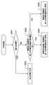
- step S201 when it is determined that the analysis request has arrived, the control device 29 determines whether or not the maximum processing is required (step S201). When it is determined that it is necessary, the process proceeds to step S202, and the analysis is executed in all the analysis tanks 50 (step S202). On the other hand, if it is not determined to be necessary, the process proceeds to step S203, and it is determined whether or not the residual liquid amount of the reagent in the analysis tank having a large remaining measurable number is large (step S203). When it is determined that the amount is large, the analysis tank 50 having a large number of remaining measurable quantities and a large amount of residual liquid is preferentially used (step S204). On the other hand, when it is not determined that the number is large, the analysis tank 50 having a large number of remaining measurable numbers is preferentially used in the distribution in the middle of the case where the distribution is equal to the distribution in step S204 (step S205).
- control device 29 selects the analysis tank 50 to be used for the measurement based on the number of samples held in the post-analysis buffer 62 in addition to the remaining measurable number.
- step S203 in FIG. 5 is replaced with a step of "determining whether or not the number of samples held in the post-analysis buffer is equal to or greater than a predetermined amount".
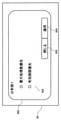
- the analysis tank selection screen 600 shown in FIG. 6 is a screen for selecting whether to prioritize the maximum number of processes or the expiration date. Check the check box 602 for the priority item and press the apply button 604. It is applied by doing. To close the analysis tank selection screen 600, press the close button 605.
- the analysis tank selection screen 700 shown in FIG. 7 is a screen for the user to select the analysis tank 50 for which the analysis is prioritized and executed, and is a target as a judgment material for determining which is prioritized.
- the tank display area 703 where the type of the analysis tank 50 is displayed, the electrode residual measurable number display area 704 where the number of remaining measurements of each ion-sensitive film is displayed, and the expiration date of the ion-sensitive film are displayed.
- Each state is displayed in the expiration date display area 705 and the reagent state display area 706 in which the remaining measurable number of each reagent and the expiration date thereof are displayed.
- the user applies by checking the check box 702 and pressing the apply button 707 based on the displayed numerical value.
- the ISE electrode 1 and reagents have a usable (valid) expiration date in addition to the remaining measurable number, and when you want to preferentially use the specified analysis tank 50 and quickly use up consumables that are nearing the expiration date. Is also valid.
- the above-mentioned electrolyte analyzer 100 of Example 1 of the present invention controls the operation of the plurality of analyzers 50 having the ISE electrode 1 for measuring the concentration of the electrolyte of the sample and the operation in the electrolyte analyzer 100 including the analyzer 50.
- the ISE electrode 1 of a plurality of analysis tanks 50 is provided with a control device 29 for analyzing the same analysis item, and the control device 29 is used to measure the remaining measurable number and the measurement request of each of the plurality of ISE electrodes 1.
- the analysis tank 50 to be used for measurement is selected from the plurality of analysis tanks 50.
- the measurement can be continued without using the analysis tank 50 in which the remaining measurable number is 0, but there is a demerit that the maximum processing capacity cannot be maintained due to the decrease in the analysis tank 50. there were.
- the analysis tank 50 for example, by selecting the analysis tank 50 to be used according to the remaining measurable number, when the analysis request status is close to the maximum processing capacity, the analysis operation can be performed with priority given to the maintenance of the processing capacity.
- the request status is intermittent, the number of remaining measurable times of the plurality of analytical tanks 50 can be made uniform by preferentially using the analytical tank 50 having a large number of remaining measurable numbers. In this way, since the user can arrange the timing for replacing the consumables, the replacement of the consumables can be performed at a more appropriate timing as compared with the conventional case, and the analysis capacity of each analysis tank 50 can be fully exhibited. can.
- the control device 29 preferentially uses the analysis tank 50 having the largest remaining measurable number. Therefore, while the maximum processing capacity is maintained when necessary, the remaining measurable number is smoothed when it is not needed, so analysis that takes into consideration the replacement of consumables while making better use of the analysis processing capacity of the device. Is possible.
- control device 29 is consumed including the reagent by selecting the analysis tank 50 to be used for the measurement based on the residual liquid amount of the reagent used in the analysis tank 50 in addition to the remaining measurable number. It becomes possible to match the frequency of product replacement, and it becomes possible to replace consumables at a timing that is more convenient for the user. For example, by aligning the replacement of the ISE electrode 1 and the reagent bottle, the timing at which the analysis must be stopped can be approached and shortened as much as possible.
- a post-analysis buffer 62 for transporting the sample container 15 after the completion of the analysis operation is further provided, and the control device 29 measures based on the number of samples held in the post-analysis buffer 62 in addition to the remaining measurable number.
- the ISE electrode 1 has an identification medium 1A for performing individual identification, further includes a reading device 1B for reading the individual identification information recorded on the identification medium 1A, and the control device 29 is a reading device 1B.
- the device can automatically determine the remaining measurable number.
- Example 2 The electrolyte analyzer of Example 2 of the present invention will be described with reference to FIGS. 8 to 10.
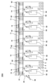
- FIG. 8 is a diagram showing the overall configuration of the electrolyte analyzer of the second embodiment
- FIGS. 9 and 10 are diagrams showing a screen for selecting an analysis tank to be preferentially used, which is displayed on the display device of the electrolyte analyzer. be.
- the electrolyte analyzer 100A of the second embodiment shown in FIG. 8 includes one control device 29 and one display device 80 among the electrolyte analyzer 100 shown in FIG. 2, and a unit having two analysis tanks 50 and transporting the unit. It is a configuration that has a total of 5 units related to. In the configuration shown in FIG. 8, the number of analysis tanks 50 provided in the analysis unit does not have to be two, but may be one or three or more.
- control device 29 is used for the sample probe 14 used for dispensing and the subsequent measurement according to the remaining measurable number of each of the plurality of analyzers 50 and the measurement request status. Select the analysis tank 50 to be used.
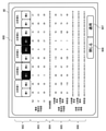
- the dispensing mechanism selection screen 800 as shown in FIG. 9 can be used.
- the dispensing mechanism selection screen 800 shown in FIG. 9 is a screen for indirectly selecting an analysis unit having an analysis tank 50 in which the user preferentially executes analysis by selecting a sample probe 14.
- the dispensing mechanism selection area 802 on which the type of the analysis unit of the target is displayed and the number of remaining measurements of each ion-sensitive film are displayed.
- Area 803, expiration date display area 804 where the expiration date of the ion-sensitive membrane is displayed, reagent remaining measurable number display area 805 where the remaining measurable number of each reagent is displayed, and the expiration date of each reagent are displayed.
- Each state is displayed in the reagent expiration date display area 806.
- the user selects the corresponding analysis unit of the dispensing mechanism selection area 802 based on the displayed numerical value, and presses the apply button 807 to apply the analysis.
- the analysis unit preferentially used for analysis, and in the case of FIG. 9, the analysis unit 4 can be highlighted.
- the number of analysis tanks 50 that can be selected is not particularly limited, and may be 2 or more.
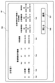
- the analysis tank selection screen 900 shown in FIG. 10 is a screen for the user to select an analysis tank 50 for which analysis is prioritized and executed, and is a target analysis tank as a judgment material for determining which is prioritized.
- the tank selection area 902 where 50 types are displayed, the electrode residual measurable number display area 903 where the number of remaining measurements of each ion-sensitive film is displayed, and the expiration date display where the expiration date of the ion-sensitive film is displayed.
- Each state is displayed in the area 904, the reagent remaining measurable number display area 905 in which the remaining measurable number of each reagent is displayed, and the reagent expiration date display area 906 in which the reagent expiration date is displayed.
- the user selects the corresponding analysis unit in the tank selection area 902 based on the displayed numerical value, and presses the apply button 907 to apply the analysis. To close the analysis tank selection screen 900, press the close button 908.
- the analysis tank 50 preferentially used for analysis, and in the case of FIG. 10, the analysis tank 1 of the analysis unit 2, the analysis tank 2 of the analysis unit 3, and the analysis tank 1 of the analysis unit 4 are highlighted. Can be displayed.
- the electrolyte analyzer of Example 2 of the present invention also has almost the same effect as the electrolyte analyzer of Example 1 described above.
- the plurality of analysis tanks 50 share a sample probe 14 for dispensing a sample to the analysis tank 50, and when a plurality of sample probes 14 are provided, the control device 29 is a control device 29 for each of the plurality of analysis tanks 50.
Landscapes
- General Health & Medical Sciences (AREA)
- Health & Medical Sciences (AREA)
- General Physics & Mathematics (AREA)
- Analytical Chemistry (AREA)
- Pathology (AREA)
- Immunology (AREA)
- Biochemistry (AREA)
- Physics & Mathematics (AREA)
- Life Sciences & Earth Sciences (AREA)
- Chemical & Material Sciences (AREA)
- Public Health (AREA)
- Epidemiology (AREA)
- Engineering & Computer Science (AREA)
- Primary Health Care (AREA)
- Medical Informatics (AREA)
- Automatic Analysis And Handling Materials Therefor (AREA)
Abstract
Description
本発明の実施例1の電解質分析装置について図1乃至図7を用いて説明する。
本発明の実施例2の電解質分析装置について図8乃至図10を用いて説明する。図8は本実施例2の電解質分析装置の全体構成を示す図、図9および図10は電解質分析装置の表示装置に表示される、優先的に使用する分析槽を選択する画面を示す図である。
なお、本発明は、上記の実施例に限定されるものではなく、様々な変形例が含まれる。上記の実施例は本発明を分かりやすく説明するために詳細に説明したものであり、必ずしも説明した全ての構成を備えるものに限定されるものではない。
1A…識別媒体
1B…読取装置
2…比較電極
3…内部標準液ボトル
4…希釈液ボトル
5…比較電極液ボトル
6…吸引ノズル
7…脱ガス機構
8…内部標準液シリンジ
9…希釈液シリンジ
10…シッパシリンジ
11…希釈槽
12…プレヒート
13…シッパノズル
14…サンプルプローブ(分注機構)
15…サンプル容器
16…フィルタ
17,18,19,20,21,22,30,31,32…電磁弁
23…ピンチ弁
24…希釈液ノズル
25…内部標準液ノズル
26…第1の廃液ノズル
27…電圧計
28…アンプ
29…制御装置(制御部)
33…真空ポンプ
34…真空ビン
35…廃液受け
36…第2の廃液ノズル
50…分析槽
55…グリッパ
61…分析前バッファ
62…分析後バッファ
65,66…分注ライン
71…搬送ライン
80…表示装置
90…搬送容器
100,100A…電解質分析装置
501…残測定可能数管理画面
503,703…槽表示領域
504…種表示領域
505…残測定回数表示領域
506,705,804,904…有効期限表示領域
508,605,708,808,908…閉じるボタン
600,700,900…分析槽選択画面
602,702…チェックボックス
604,707,807,907…適用ボタン
704,803,903…電極残測定可能数表示領域
706…試薬状態表示領域
800…分注機構選択画面
802…分注機構選択領域
805,905…試薬残測定可能数表示領域
806,906…試薬有効期限表示領域
902…槽選択領域
Claims (6)
- サンプルの電解質濃度を分析する電解質分析装置であって、
前記サンプルの電解質の濃度を測定する消耗品を有する複数の分析槽と、
前記分析槽を含めた前記電解質分析装置内の動作を制御する制御部と、を備え、
複数の前記分析槽の前記消耗品は、同一分析項目を分析するものであり、
前記制御部は、複数の前記消耗品の各々の残測定可能数と測定依頼状況とに応じて、複数の前記分析槽の中から測定に使用する分析槽を選択する
ことを特徴とする電解質分析装置。 - 請求項1に記載の電解質分析装置において、
前記制御部は、当該電解質分析装置が所定の時間以内に処理する測定依頼数が最大処理能力未満と判断された場合は、最も残測定可能数が多い分析槽を優先的に用いる
ことを特徴とする電解質分析装置。 - 請求項1に記載の電解質分析装置において、
前記制御部は、前記残測定可能数に加えて、前記分析槽にて使用される試薬の残液量にも基づいて測定に使用する前記分析槽を選択する
ことを特徴とする電解質分析装置。 - 請求項1に記載の電解質分析装置において、
分析動作完了後のサンプル容器を他に搬送するサンプルバッファ部を更に備え、
前記制御部は、前記残測定可能数に加えて、前記サンプルバッファ部のサンプル保有数にも基づいて測定に使用する前記分析槽を選択する
ことを特徴とする電解質分析装置。 - 請求項1に記載の電解質分析装置において、
複数の分析槽は、前記サンプルを前記分析槽に分注する分注機構を共有しており、
前記分注機構を複数備えた場合において、前記制御部は、複数の前記分析槽の各々の残測定可能数と測定依頼状況とに応じて、分注に用いる前記分注機構及び測定に使用する前記分析槽を選択する
ことを特徴とする電解質分析装置。 - 請求項1に記載の電解質分析装置において、
前記消耗品は、個体識別を行うための識別媒体を有しており、
前記識別媒体に記録されている個体識別情報を読み取る読取装置を更に備え、
前記制御部は、前記読取装置により読み取られた前記個体識別情報に基づき前記残測定可能数を管理する
ことを特徴とする電解質分析装置。
Priority Applications (4)
| Application Number | Priority Date | Filing Date | Title |
|---|---|---|---|
| CN202180045584.2A CN115769081B (zh) | 2020-07-16 | 2021-03-11 | 电解质分析装置 |
| JP2022536130A JP7391224B2 (ja) | 2020-07-16 | 2021-03-11 | 電解質分析装置 |
| US18/015,971 US12385935B2 (en) | 2020-07-16 | 2021-03-11 | Electrolyte analyzer |
| EP21841428.2A EP4184174B1 (en) | 2020-07-16 | 2021-03-11 | Electrolyte analysis device |
Applications Claiming Priority (2)
| Application Number | Priority Date | Filing Date | Title |
|---|---|---|---|
| JP2020-122088 | 2020-07-16 | ||
| JP2020122088 | 2020-07-16 |
Publications (1)
| Publication Number | Publication Date |
|---|---|
| WO2022014096A1 true WO2022014096A1 (ja) | 2022-01-20 |
Family
ID=79554640
Family Applications (1)
| Application Number | Title | Priority Date | Filing Date |
|---|---|---|---|
| PCT/JP2021/009801 Ceased WO2022014096A1 (ja) | 2020-07-16 | 2021-03-11 | 電解質分析装置 |
Country Status (5)
| Country | Link |
|---|---|
| US (1) | US12385935B2 (ja) |
| EP (1) | EP4184174B1 (ja) |
| JP (1) | JP7391224B2 (ja) |
| CN (1) | CN115769081B (ja) |
| WO (1) | WO2022014096A1 (ja) |
Cited By (1)
| Publication number | Priority date | Publication date | Assignee | Title |
|---|---|---|---|---|
| WO2024247823A1 (ja) | 2023-05-30 | 2024-12-05 | 株式会社日立ハイテク | 自動分析装置及び分析槽の割当方法 |
Citations (4)
| Publication number | Priority date | Publication date | Assignee | Title |
|---|---|---|---|---|
| JP2011033425A (ja) * | 2009-07-31 | 2011-02-17 | Hitachi High-Technologies Corp | 自動分析装置 |
| JP2011112489A (ja) * | 2009-11-26 | 2011-06-09 | Hitachi High-Technologies Corp | 動的搬送計画装置及び動的搬送計画方法 |
| JP2012189405A (ja) | 2011-03-10 | 2012-10-04 | Jeol Ltd | 電解質測定方法及び電解質測定装置 |
| JP2015148500A (ja) * | 2014-02-06 | 2015-08-20 | コニカミノルタ株式会社 | イムノアッセイ装置およびイムノアッセイ法 |
Family Cites Families (6)
| Publication number | Priority date | Publication date | Assignee | Title |
|---|---|---|---|---|
| US4649028A (en) * | 1985-03-27 | 1987-03-10 | Medica Corporation | Electrolyte analyzer |
| JP4934449B2 (ja) * | 2007-02-02 | 2012-05-16 | ベックマン コールター, インコーポレイテッド | 分析装置 |
| JP2010151672A (ja) * | 2008-12-25 | 2010-07-08 | Beckman Coulter Inc | 自動分析装置 |
| JP6177532B2 (ja) * | 2013-01-23 | 2017-08-09 | 株式会社日立ハイテクノロジーズ | 自動分析システムおよび制御方法 |
| JP6161909B2 (ja) * | 2013-01-29 | 2017-07-12 | 株式会社日立ハイテクノロジーズ | 自動分析装置 |
| US12123884B2 (en) * | 2018-12-11 | 2024-10-22 | Hitachi High-Tech Corporation | Monitoring the cleaning status of an automatic analyzer |
-
2021
- 2021-03-11 WO PCT/JP2021/009801 patent/WO2022014096A1/ja not_active Ceased
- 2021-03-11 US US18/015,971 patent/US12385935B2/en active Active
- 2021-03-11 EP EP21841428.2A patent/EP4184174B1/en active Active
- 2021-03-11 CN CN202180045584.2A patent/CN115769081B/zh active Active
- 2021-03-11 JP JP2022536130A patent/JP7391224B2/ja active Active
Patent Citations (4)
| Publication number | Priority date | Publication date | Assignee | Title |
|---|---|---|---|---|
| JP2011033425A (ja) * | 2009-07-31 | 2011-02-17 | Hitachi High-Technologies Corp | 自動分析装置 |
| JP2011112489A (ja) * | 2009-11-26 | 2011-06-09 | Hitachi High-Technologies Corp | 動的搬送計画装置及び動的搬送計画方法 |
| JP2012189405A (ja) | 2011-03-10 | 2012-10-04 | Jeol Ltd | 電解質測定方法及び電解質測定装置 |
| JP2015148500A (ja) * | 2014-02-06 | 2015-08-20 | コニカミノルタ株式会社 | イムノアッセイ装置およびイムノアッセイ法 |
Non-Patent Citations (1)
| Title |
|---|
| See also references of EP4184174A4 |
Cited By (2)
| Publication number | Priority date | Publication date | Assignee | Title |
|---|---|---|---|---|
| WO2024247823A1 (ja) | 2023-05-30 | 2024-12-05 | 株式会社日立ハイテク | 自動分析装置及び分析槽の割当方法 |
| EP4722727A1 (en) | 2023-05-30 | 2026-04-08 | Hitachi High-Tech Corporation | Automatic analysis device and method for allocating analysis tank |
Also Published As
| Publication number | Publication date |
|---|---|
| EP4184174A1 (en) | 2023-05-24 |
| EP4184174A4 (en) | 2024-07-31 |
| JP7391224B2 (ja) | 2023-12-04 |
| JPWO2022014096A1 (ja) | 2022-01-20 |
| US20230288439A1 (en) | 2023-09-14 |
| US12385935B2 (en) | 2025-08-12 |
| CN115769081A (zh) | 2023-03-07 |
| EP4184174B1 (en) | 2025-03-05 |
| CN115769081B (zh) | 2025-11-18 |
Similar Documents
| Publication | Publication Date | Title |
|---|---|---|
| JP7836369B2 (ja) | 自動分析装置及び自動分析方法 | |
| JP4558017B2 (ja) | 自動分析装置および自動分析装置の使用方法 | |
| EP1832879B1 (en) | Centralized monitoring system, analyzing system and centralized monitoring method | |
| US8409507B2 (en) | Automatic analyzer | |
| US7672878B2 (en) | Consumables supply system | |
| CN111936863B (zh) | 自动分析装置 | |
| JP2002350451A (ja) | 自動分析装置、自動分析システム、自動分析装置管理方法および消耗品管理方法 | |
| JP7234216B2 (ja) | 電解質分析装置 | |
| CN112585473B (zh) | 自动分析装置 | |
| CN111886502A (zh) | 自动分析装置 | |
| WO2022014096A1 (ja) | 電解質分析装置 | |
| CN113383238B (zh) | 自动分析装置 | |
| WO2023002729A1 (ja) | 自動分析装置および自動分析装置での試薬管理方法 | |
| CN114041059A (zh) | 自动分析装置 | |
| WO2022201637A1 (ja) | 自動分析装置 | |
| JP7489535B2 (ja) | 電解質分析装置 | |
| EP4685495A1 (en) | Automatic analysis device | |
| US20240125810A1 (en) | Automatic analysis system and sample distribution method | |
| JP2025112655A (ja) | 消耗品補充支援装置 | |
| WO2025220386A1 (ja) | 電解質分析装置、制御方法 |
Legal Events
| Date | Code | Title | Description |
|---|---|---|---|
| 121 | Ep: the epo has been informed by wipo that ep was designated in this application |
Ref document number: 21841428 Country of ref document: EP Kind code of ref document: A1 |
|
| DPE1 | Request for preliminary examination filed after expiration of 19th month from priority date (pct application filed from 20040101) | ||
| ENP | Entry into the national phase |
Ref document number: 2022536130 Country of ref document: JP Kind code of ref document: A |
|
| WWE | Wipo information: entry into national phase |
Ref document number: 202180045584.2 Country of ref document: CN |
|
| NENP | Non-entry into the national phase |
Ref country code: DE |
|
| ENP | Entry into the national phase |
Ref document number: 2021841428 Country of ref document: EP Effective date: 20230216 |
|
| WWG | Wipo information: grant in national office |
Ref document number: 18015971 Country of ref document: US |