WO2022014100A1 - ロータの製造方法およびロータ - Google Patents
ロータの製造方法およびロータ Download PDFInfo
- Publication number
- WO2022014100A1 WO2022014100A1 PCT/JP2021/011728 JP2021011728W WO2022014100A1 WO 2022014100 A1 WO2022014100 A1 WO 2022014100A1 JP 2021011728 W JP2021011728 W JP 2021011728W WO 2022014100 A1 WO2022014100 A1 WO 2022014100A1
- Authority
- WO
- WIPO (PCT)
- Prior art keywords
- shaft
- insertion hole
- laminated core
- rotor
- shaft insertion
- Prior art date
- Legal status (The legal status is an assumption and is not a legal conclusion. Google has not performed a legal analysis and makes no representation as to the accuracy of the status listed.)
- Ceased
Links
Images




Classifications
-
- H—ELECTRICITY
- H02—GENERATION; CONVERSION OR DISTRIBUTION OF ELECTRIC POWER
- H02K—DYNAMO-ELECTRIC MACHINES
- H02K15/00—Processes or apparatus specially adapted for manufacturing, assembling, maintaining or repairing of dynamo-electric machines
- H02K15/02—Processes or apparatus specially adapted for manufacturing, assembling, maintaining or repairing of dynamo-electric machines of stator or rotor bodies
- H02K15/03—Processes or apparatus specially adapted for manufacturing, assembling, maintaining or repairing of dynamo-electric machines of stator or rotor bodies having permanent magnets
-
- B—PERFORMING OPERATIONS; TRANSPORTING
- B21—MECHANICAL METAL-WORKING WITHOUT ESSENTIALLY REMOVING MATERIAL; PUNCHING METAL
- B21D—WORKING OR PROCESSING OF SHEET METAL OR METAL TUBES, RODS OR PROFILES WITHOUT ESSENTIALLY REMOVING MATERIAL; PUNCHING METAL
- B21D26/00—Shaping without cutting otherwise than using rigid devices or tools or yieldable or resilient pads, i.e. applying fluid pressure or magnetic forces
- B21D26/02—Shaping without cutting otherwise than using rigid devices or tools or yieldable or resilient pads, i.e. applying fluid pressure or magnetic forces by applying fluid pressure
- B21D26/033—Deforming tubular bodies
-
- B—PERFORMING OPERATIONS; TRANSPORTING
- B21—MECHANICAL METAL-WORKING WITHOUT ESSENTIALLY REMOVING MATERIAL; PUNCHING METAL
- B21D—WORKING OR PROCESSING OF SHEET METAL OR METAL TUBES, RODS OR PROFILES WITHOUT ESSENTIALLY REMOVING MATERIAL; PUNCHING METAL
- B21D26/00—Shaping without cutting otherwise than using rigid devices or tools or yieldable or resilient pads, i.e. applying fluid pressure or magnetic forces
- B21D26/02—Shaping without cutting otherwise than using rigid devices or tools or yieldable or resilient pads, i.e. applying fluid pressure or magnetic forces by applying fluid pressure
- B21D26/033—Deforming tubular bodies
- B21D26/047—Mould construction
-
- B—PERFORMING OPERATIONS; TRANSPORTING
- B21—MECHANICAL METAL-WORKING WITHOUT ESSENTIALLY REMOVING MATERIAL; PUNCHING METAL
- B21D—WORKING OR PROCESSING OF SHEET METAL OR METAL TUBES, RODS OR PROFILES WITHOUT ESSENTIALLY REMOVING MATERIAL; PUNCHING METAL
- B21D39/00—Application of procedures in order to connect objects or parts, e.g. coating with sheet metal otherwise than by plating; Tube expanders
- B21D39/06—Application of procedures in order to connect objects or parts, e.g. coating with sheet metal otherwise than by plating; Tube expanders of tubes in openings, e.g. rolling-in
-
- B—PERFORMING OPERATIONS; TRANSPORTING
- B21—MECHANICAL METAL-WORKING WITHOUT ESSENTIALLY REMOVING MATERIAL; PUNCHING METAL
- B21D—WORKING OR PROCESSING OF SHEET METAL OR METAL TUBES, RODS OR PROFILES WITHOUT ESSENTIALLY REMOVING MATERIAL; PUNCHING METAL
- B21D39/00—Application of procedures in order to connect objects or parts, e.g. coating with sheet metal otherwise than by plating; Tube expanders
- B21D39/08—Tube expanders
-
- B—PERFORMING OPERATIONS; TRANSPORTING
- B23—MACHINE TOOLS; METAL-WORKING NOT OTHERWISE PROVIDED FOR
- B23P—METAL-WORKING NOT OTHERWISE PROVIDED FOR; COMBINED OPERATIONS; UNIVERSAL MACHINE TOOLS
- B23P11/00—Connecting or disconnecting metal parts or objects by metal-working techniques not otherwise provided for
- B23P11/005—Connecting or disconnecting metal parts or objects by metal-working techniques not otherwise provided for by expanding or crimping
-
- B—PERFORMING OPERATIONS; TRANSPORTING
- B23—MACHINE TOOLS; METAL-WORKING NOT OTHERWISE PROVIDED FOR
- B23P—METAL-WORKING NOT OTHERWISE PROVIDED FOR; COMBINED OPERATIONS; UNIVERSAL MACHINE TOOLS
- B23P15/00—Making specific metal objects by operations not covered by a single other subclass or a group in this subclass
-
- H—ELECTRICITY
- H02—GENERATION; CONVERSION OR DISTRIBUTION OF ELECTRIC POWER
- H02K—DYNAMO-ELECTRIC MACHINES
- H02K1/00—Details of the magnetic circuit
- H02K1/06—Details of the magnetic circuit characterised by the shape, form or construction
- H02K1/22—Rotating parts of the magnetic circuit
- H02K1/27—Rotor cores with permanent magnets
- H02K1/2706—Inner rotors
- H02K1/272—Inner rotors the magnetisation axis of the magnets being perpendicular to the rotor axis
- H02K1/274—Inner rotors the magnetisation axis of the magnets being perpendicular to the rotor axis the rotor consisting of two or more circumferentially positioned magnets
- H02K1/2753—Inner rotors the magnetisation axis of the magnets being perpendicular to the rotor axis the rotor consisting of two or more circumferentially positioned magnets the rotor consisting of magnets or groups of magnets arranged with alternating polarity
- H02K1/276—Magnets embedded in the magnetic core, e.g. interior permanent magnets [IPM]
-
- H—ELECTRICITY
- H02—GENERATION; CONVERSION OR DISTRIBUTION OF ELECTRIC POWER
- H02K—DYNAMO-ELECTRIC MACHINES
- H02K1/00—Details of the magnetic circuit
- H02K1/06—Details of the magnetic circuit characterised by the shape, form or construction
- H02K1/22—Rotating parts of the magnetic circuit
- H02K1/28—Means for mounting or fastening rotating magnetic parts on to, or to, the rotor structures
-
- H—ELECTRICITY
- H02—GENERATION; CONVERSION OR DISTRIBUTION OF ELECTRIC POWER
- H02K—DYNAMO-ELECTRIC MACHINES
- H02K7/00—Arrangements for handling mechanical energy structurally associated with dynamo-electric machines, e.g. structural association with mechanical driving motors or auxiliary dynamo-electric machines
- H02K7/003—Couplings; Details of shafts
-
- B—PERFORMING OPERATIONS; TRANSPORTING
- B23—MACHINE TOOLS; METAL-WORKING NOT OTHERWISE PROVIDED FOR
- B23P—METAL-WORKING NOT OTHERWISE PROVIDED FOR; COMBINED OPERATIONS; UNIVERSAL MACHINE TOOLS
- B23P2700/00—Indexing scheme relating to the articles being treated, e.g. manufactured, repaired, assembled, connected or other operations covered in the subgroups
- B23P2700/12—Laminated parts
Definitions
- the present invention relates to a rotor manufacturing method and a rotor.
- Japanese Patent Application Laid-Open No. 2001-268858 discloses a rotor for a motor including a hollow rotating shaft having a pipe structure and a laminated iron core into which the rotating shaft is inserted.
- the rotating shaft is inserted into a through hole provided in the center of the laminated iron core.
- the rotating shaft is provided with a retaining portion formed by a hydroforming method.
- the retaining portion is formed by expanding the rotating shaft toward the outer diameter side by the hydroforming method. Further, the retaining portion is provided so as to sandwich the laminated iron core in the axial direction.
- the laminated iron core is formed by laminating a silicon steel plate provided with one key groove.
- the rotation shaft expands by the hydroforming method, so that a convex portion that meshes with the key groove is formed.
- the deviation of the laminated iron core with respect to the rotation axis in the rotation direction is suppressed.
- the present invention has been made to solve the above-mentioned problems, and one object of the present invention is to shift the laminated core in the rotation direction with respect to the shaft when the shaft is fixed to the laminated core by hydroforming. It is an object of the present invention to provide a rotor and a method for manufacturing the rotor, which can prevent the balance in the rotation of the rotor from being deteriorated while preventing the above.
- the method for manufacturing a rotor in the first aspect of the present invention comprises a laminated core including a shaft insertion hole into which a tubular shaft is inserted and a magnet insertion hole into which a permanent magnet is inserted.
- a method for manufacturing a rotor to be provided which is a distance between the apex of a shaft insertion hole provided in the center of the laminated core and having a non-circular shape including a plurality of apex and the outer peripheral surface of the shaft when viewed from the axial direction of the laminated core.
- the outer peripheral surface of the shaft is inside the shaft insertion hole when viewed from the axial direction by hydroforming, which is expanded by pressurizing the liquid filled inside the shaft. It comprises a fixing step of fixing the shaft to the laminated core by deforming it into a non-circular shape along the peripheral surface.
- the apex of the shaft insertion hole when viewed from the axial direction of the laminated core, the apex of the shaft insertion hole having a non-circular shape including a plurality of apex and the outer peripheral surface of the shaft
- a fixing step of fixing the shaft to the laminated core is performed by deforming the outer peripheral surface of the shaft into a non-circular shape along the inner peripheral surface of the shaft insertion hole when viewed from the axial direction.
- the rotor in the second aspect of the present invention comprises a tubular shaft, a permanent magnet, and a laminated core including a shaft insertion hole into which the shaft is inserted and a magnet insertion hole into which the permanent magnet is inserted.
- the shaft is fixed to the laminated core by hydroforming, which is expanded by pressurizing the liquid filled inside the shaft, and the shaft insertion hole is the center of the laminated core when viewed from the axial direction of the laminated core.
- the laminated core has a non-circular shape provided in the portion and includes a plurality of vertices, and the number of vertices and sides of the shaft insertion hole is an integral multiple of the number of poles, or the number of poles is a number of poles other than the number of poles. It is configured to be a number divided by an integer of.
- the shaft insertion hole has a non-circular shape including a plurality of vertices when viewed from the axial direction of the laminated core. This regulates the rotational deviation of the laminated core with respect to the shaft at each of the plurality of vertices.
- the laminated core is configured such that the number of vertices and sides of the shaft insertion hole is an integral multiple of the number of poles or the number of poles divided by a fraction of the number of poles other than the number of poles.
- the present invention it is possible to prevent the balance in the rotation of the rotor from being deteriorated while preventing the laminated core from being displaced with respect to the shaft in the rotation direction.
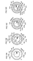
- FIG. 9 is a partially enlarged view of the vicinity of the magnetic pole forming portion of FIG. It is a flow figure which shows the manufacturing method of the rotor by 2nd Embodiment. It is a plan sectional view which shows the structure of the laminated core by the modification of 1st Embodiment. It is a plan sectional view which shows the structure of the laminated core by the modification of 2nd Embodiment.
- the "axial direction” means the direction along the rotation axis C of the rotor 1, and means the Z direction in the drawing. Further, the “diametrical direction” means the radial direction of the rotor 1 (R1 direction or R2 direction), and the “circumferential direction” means the circumferential direction of the rotor 1 (E1 direction or E2 direction).
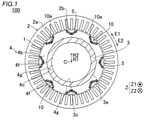
- the rotary electric machine 100 includes a rotor 1 and a stator 2. Further, the rotor 1 and the stator 2 are each formed in an annular shape. The rotor 1 is arranged so as to face the inside of the stator 2 in the radial direction. That is, in the first embodiment, the rotary electric machine 100 is configured as an inner rotor type rotary electric machine. Further, a shaft 3 is arranged inside the rotor 1 (rotor core 4) in the radial direction. The shaft 3 is connected to an engine, an axle, or the like via a rotational force transmitting member such as a gear.
- the rotary electric machine 100 is configured as a motor, a generator, or a motor / generator, and is configured to be mounted on a vehicle.
- the rotor 1 includes a rotor core 4.
- the rotor core 4 includes a laminated core 4b in which a plurality of electrical steel sheets 4a (see FIG. 3) are laminated and have magnet insertion holes 10a extending in the stacking direction of the electrical steel sheets 4a.
- the rotor 1 (rotor core 4) includes a permanent magnet 5. The permanent magnet 5 is inserted (arranged) into the magnet insertion hole 10a of the laminated core 4b.
- a plurality of magnet insertion holes 10a (16 in the first embodiment) are provided in the laminated core 4b. That is, the rotary electric machine 100 is configured as an embedded permanent magnet type motor (IPM motor: International Permanent Magnet Motor).
- IPM motor International Permanent Magnet Motor
- the laminated core 4b has a magnetic pole including a pair of magnet insertion holes 10a adjacent to each other in the circumferential direction and a bridge portion 10b (see FIG. 2) arranged between the magnet insertion holes 10a of the pair of magnet insertion holes 10a.
- a plurality of magnetic pole forming portions 10 to be formed are included.
- the bridge portion 10b is provided so as to connect the radial inner portion 4h of the laminated core 4b and the radial outer portion 4l of the laminated core 4b.
- Eight magnetic pole forming portions 10 are provided in the laminated core 4b at equal angular intervals along the circumferential direction when viewed from the rotation axis C direction. Further, the pair of magnet insertion holes 10a in the magnetic pole forming portion 10 are arranged in a V shape.
- the bridge portion 10b is provided so as to connect a portion radially outside the magnet insertion hole 10a and a portion radially inside the magnet insertion hole 10a in the laminated core 4b. There is.
- the bridge portion 10b is provided so as to extend in the radial direction.
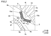
- the circumferential width W1 of the bridge portion 10b is smaller than the radial length L1 of the bridge portion 10b.
- the rotor core 4 is rotated around the rotation axis C.
- the rotor core 4 (laminated core 4b) includes a shaft insertion hole 4c provided in the central portion of the laminated core 4b when viewed from the axial direction of the laminated core 4b (viewed from the Z1 direction side).
- the shaft 3 is inserted into the shaft insertion hole 4c of the laminated core 4b.
- the rotational force of the shaft 3 is transmitted to the laminated core 4b, and the laminated core 4b is configured to rotate.
- the stator 2 includes a stator core 2a and a coil 2b wound (arranged) around the stator core 2a.
- the stator core 2a is arranged on the outer side in the radial direction of the rotor core 4.
- the stator core 2a is configured such that, for example, a plurality of electromagnetic steel sheets (silicon steel sheets) are laminated in the axial direction so that magnetic flux can pass through the stator core 2a.
- the coil 2b is connected to an external power supply unit and is configured to supply electric power (for example, three-phase alternating current electric power).
- the coil 2b is configured to generate a magnetic field by being supplied with electric power.
- the rotor 1 and the shaft 3 are configured to rotate with respect to the stator 2 as the engine or the like is driven, even when electric power is not supplied to the coil 2b.
- the coil 2b is arranged over the entire circumference of the stator core 2a.
- the permanent magnet 5 has a rectangular cross section orthogonal to the axial direction.
- the permanent magnet 5 is configured so that the magnetizing direction (magnetism direction) is the lateral direction.
- a resin material (not shown) for fixing the permanent magnet 5 arranged in the magnet insertion hole 10a is arranged.
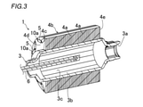
- the shaft 3 is formed in a cylindrical shape.
- the shaft 3 is provided with an insertion hole 3a into which an oil injection portion 6 described later is inserted.
- the shaft 3 is fixed to the laminated core 4b by hydroforming, which is expanded by pressurizing the liquid 800 (see FIG. 8) filled inside the shaft 3.
- the shaft 3 includes a fixed portion 3b fixed to the laminated core 4b.
- the fixed portion 3b is the entire portion of the shaft 3 inserted into the shaft insertion hole 4c of the laminated core 4b.
- the rotor 1 is provided with an oil injection unit 6 which is inserted into the inside of the shaft 3 through the insertion hole 3a and injects cooling oil inside the shaft 3.
- the shaft insertion hole 4c has a non-circular shape including a plurality of vertices 4f when viewed from the axial direction.
- the shaft insertion hole 4c has a regular polygonal shape when viewed from the axial direction.
- the shaft insertion hole 4c has a regular hexadecagonal shape when viewed from the axial direction.
- the shaft insertion hole 4c may have a regular polygon (for example, a regular hexagon) other than a regular hexadecagon when viewed from the axial direction.
- the outer peripheral surface 3e (inner peripheral surface 3c) of the shaft 3 expanded by hydroforming has a regular hexadecagonal shape along the shaft insertion hole 4c of the rotor core 4 when viewed from the axial direction.
- the laminated core 4b is configured so that the number of the vertices 4f and the sides 4g of the shaft insertion hole 4c is an integral multiple of the number of poles.
- the number of poles (the number of magnetic pole forming portions 10) is eight, and the number of vertices 4f and sides 4g of the shaft insertion hole 4c is 16. That is, the number of vertices 4f and sides 4g of the shaft insertion hole 4c is twice the number of poles.
- the apex 4f of the shaft insertion hole 4c is a portion corresponding to an intersection of adjacent sides 4g, and is not necessarily a pin angle but may have a constant curvature. Further, the side 4g does not necessarily have to be a straight line, and may have a constant curvature.
- the apex 4f of the shaft insertion hole 4c overlaps the bridge portion 10b (all eight bridge portions 10b) of the magnetic pole forming portion 10 in the circumferential direction when viewed from the axial direction. It is configured to be placed in position.
- the apex 4f that does not overlap with the bridge portion 10b in the circumferential direction is arranged at a position that overlaps with the central portion in the circumferential direction of the magnetic pole forming portions 10 adjacent to each other in the circumferential direction.
- the apex 4f arranged at a position overlapping the bridge portion 10b in the circumferential direction is provided so as to overlap with the vicinity of the center in the circumferential direction of the bridge portion 10b in the circumferential direction.
- the laminated core 4b is configured such that the magnet insertion hole 10a is arranged at a position where the magnet insertion hole 10a overlaps with the side 4g of the shaft insertion hole 4c in the circumferential direction when viewed from the axial direction.
- a radial inner portion 4h having a width W2 in the radial direction is formed between the magnet insertion hole 10a and the side 4g. Since the pair of magnet insertion holes 10a have a V-shape, the width W2 gradually decreases toward the apex 4f side arranged at a position overlapping the bridge portion 10b in the circumferential direction.
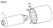
- step S1 a step of preparing the laminated core 4b and the shaft 3 is performed. Specifically, as shown in FIG. 5, a cylindrical shaft 3 and a laminated core 4b in which the shaft insertion hole 4c has a non-circular shape (regular hexadecagon) when viewed from the axial direction are prepared. At this point, the shaft 3 has a circular shape (see FIG. 7) when viewed from the axial direction.
- a non-circular shape regular hexadecagon
- the apex 4f of the shaft insertion hole 4c is arranged at a position where the apex 4f of the shaft insertion hole 4c overlaps the bridge portion 10b provided between the magnet insertion holes 10a adjacent to each other in the circumferential direction in the circumferential direction.
- the core forming step of forming the laminated core 4b is performed. Specifically, in the core forming step, when viewed from the axial direction, the apex 4f of the shaft insertion hole 4c is a magnet insertion hole 10a of a pair of magnet insertion holes 10a adjacent to each other in the circumferential direction in each of the plurality of magnetic pole forming portions 10.
- the laminated core 4b is provided between the laminated cores 4b so as to be arranged at a position overlapping with the bridge portion 10b that connects the radial outer portion 4l of the laminated core 4b and the radial inner portion 4h of the laminated core 4b. Is the process of forming.
- the core forming step performed in step S1 is an example of the "first core forming step" in the claims.
- step S2 an insertion step of inserting the shaft 3 into the shaft insertion hole 4c (see FIG. 6) is performed.
- the shaft 3 having a circular shape when viewed from the axial direction is inserted into the shaft insertion hole 4c having a regular polygonal (regular hexadecagonal) shape when viewed from the axial direction. This is the process of inserting.
- the apex 4f of the shaft insertion hole 4c is provided between the magnet insertion holes 10a adjacent to each other in the circumferential direction when viewed from the axial direction.
- This is a step of inserting the shaft 3 into the shaft insertion hole 4c of the laminated core 4b arranged at a position overlapping in the circumferential direction (see FIG. 2).
- the outer peripheral surface 3e of the shaft 3 and the inner peripheral surface 4i of the shaft insertion hole 4c are in a separated state.
- the distance between the outer peripheral surface 3e of the shaft 3 and the apex 4f of the shaft insertion hole 4c is the distance L2 when viewed from the axial direction, and the outer peripheral surface 3e of the shaft 3 and the shaft insertion hole 4c.
- the distance between the outer peripheral surface 3e of the shaft 3 and the apex 4f of all the shaft insertion holes 4c becomes equal at the distance L2, and the outer peripheral surface 3e of the shaft 3 and the sides 4g of all the shaft insertion holes 4c
- the shaft 3 is inserted (arranged) into the shaft insertion hole 4c so that the distances are equal at the distance L3.
- the distance L2 is the shortest distance between the outer peripheral surface 3e of the shaft 3 and the apex 4f of the shaft insertion hole 4c.
- the distance L3 is the shortest distance between the outer peripheral surface 3e of the shaft 3 and the side 4g of the shaft insertion hole 4c.
- the distance L2 and the distance L3 are examples of the "first distance" and the "second distance” in the claims, respectively.
- step S3 a fixing step of fixing the shaft 3 to the laminated core 4b is performed.
- the fixing step with the shaft 3 inserted in the shaft insertion hole 4c of the laminated core 4b, the outer peripheral surface 3e of the shaft 3 as viewed from the axial direction is formed on the inner circumference of the shaft insertion hole 4c by hydroforming.
- This is a step of fixing the shaft 3 to the laminated core 4b by deforming it into a non-circular shape (regular hexadecagonal shape) along the surface 4i (see FIG. 1).
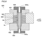
- the laminated core 4b and the shaft 3 are arranged (set) in the hydroforming molding machine 900.
- the hydroforming molding machine 900 includes an upper mold 901 that presses the laminated core 4b from the Z1 side, and a lower mold 902 that presses the laminated core 4b from the Z2 side. Further, the hydroforming molding machine 900 includes a regulation unit 903 that restricts the radial movement of the laminated core 4b from the outside in the radial direction.
- the hydroforming molding machine 900 includes an upper seal portion 904 that seals the end portion of the shaft 3 on the Z1 side and a lower seal portion 905 that seals the end portion of the shaft 3 on the Z2 side.
- the upper seal portion 904 and the lower seal portion 905 are provided with introduction paths 904a and 905a for introducing the liquid 800 inside the shaft 3, respectively.
- step S4 the permanent magnet 5 (see FIG. 1) is inserted into the magnet insertion hole 10a, and a resin material (not shown) is filled in the magnet insertion hole 10a to fix the permanent magnet 5.
- a resin material not shown
- the rotor 11 of the second embodiment unlike the first embodiment in which the apex 4f of the shaft insertion hole 4c and the bridge portion 10b are arranged so as to overlap each other in the circumferential direction, the side 14g of the shaft insertion hole 14c is the d-axis. It is placed at a position where it overlaps with the circumferential direction.
- the same configuration as that of the first embodiment is illustrated with the same reference numerals as those of the first embodiment, and the description thereof will be omitted.
- the rotary electric machine 200 includes a rotor 11 instead of the rotor 1 of the rotary electric machine 100 of the first embodiment.
- the rotor 11 includes a rotor core 14.
- the rotor core 14 includes a laminated core 14b having a magnet insertion hole 10a.
- the rotor core 14 (laminated core 14b) includes a shaft insertion hole 14c provided in the central portion of the laminated core 14b when viewed from the axial direction of the laminated core 14b (viewed from the Z1 direction side).
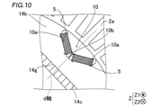
- the laminated core 14b is arranged at a position where the side 14g of the shaft insertion hole 14c overlaps with the d-axis of the laminated core 14b in the circumferential direction when viewed from the axial direction. It is configured to be.
- the d-axis means the direction of the magnetic flux created by the magnetic poles in the rotor core 14 (laminated core 14b). In the example shown in FIG. 10, since the magnetic flux passes through the bridge portion 10b, the d-axis is the direction from the rotation axis C toward the bridge portion 10b when viewed from the axial direction.
- each d-axis is formed at a position overlapping with the side 14g of the shaft insertion hole 14c in the circumferential direction.
- the apex 14f of the shaft insertion hole 14c is arranged so as to overlap the position between the magnetic pole forming portions 10 adjacent to each other in the circumferential direction in the circumferential direction.
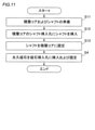
- step S11 a step of preparing the laminated core 14b and the shaft 3 is performed.
- step S11 a core forming step of forming the laminated core 14b is performed so that the side 14g of the shaft insertion hole 14c is arranged at a position overlapping the d-axis of the laminated core 14b in the circumferential direction when viewed from the axial direction. Will be done.
- the core forming step performed in step S11 is an example of the "second core forming step" in the claims.
- step S12 an insertion step of inserting the shaft 3 into the shaft insertion hole 14c is performed.
- the insertion step is performed in the shaft insertion hole 14c of the laminated core 14b arranged at a position where the side 14g of the shaft insertion hole 14c overlaps the d-axis of the laminated core 14b in the circumferential direction when viewed from the axial direction.
- step S13 a fixing step of fixing the shaft 3 to the laminated core 14b is performed.
- the fixing step with the shaft 3 inserted in the shaft insertion hole 14c of the laminated core 14b, the outer peripheral surface 3e of the shaft 3 is formed on the inner circumference of the shaft insertion hole 4c by hydroforming by hydroforming.
- This is a step of fixing the shaft 3 to the laminated core 14b by deforming it into a non-circular shape (regular hexadecagonal shape) along the surface 14i (see FIG. 1).
- the shaft (3) has a laminated core (3) that is expanded by hydroforming by pressurizing the liquid (800) filled inside the shaft (3). It is fixed to 4b, 14b). Further, the shaft insertion holes (4c, 14c) are provided in the central portion of the laminated core (4b, 14b) when viewed from the axial direction of the laminated core (4b, 14b), and a plurality of vertices (4f, 14f) are provided.
- the number of vertices (4f, 14f) and sides (4g, 14g) of the shaft insertion holes (4c, 14c) is an integral multiple of the number of poles, or the number of poles is the number of poles. It is configured to be a number divided by a fraction of the number of poles other than.
- the vertices (4f, 14f) and sides (4g, 14g) of the shaft insertion hole (4c, 14c) is an integral multiple of the number of poles
- the vertices (4f, 14f) are for each of the plurality of poles.
- the rotors (1, 11) it is possible to easily form the rotors (1, 11) so that the 14f) (sides (4g, 14g)) are evenly arranged. Further, when the number of vertices (4f, 14f) and sides (4g, 14g) is the number obtained by dividing the number of poles by the number of poles other than the number of poles, each of the above groups of poles is divided into groups of poles. On the other hand, it is possible to easily form the rotors (1, 11) so that the vertices (4f, 14f) (sides (4g, 14g)) are evenly arranged.
- the rotational displacement of the laminated cores (4b, 14b) with respect to the shaft (3) is more balancedly prevented for each of the plurality of poles or for each of the groups of poles of each divisor. can do.
- the method for manufacturing the rotor (1, 11) is a shaft insertion having a non-circular shape including a plurality of vertices (4f, 14f) when viewed from the axial direction.
- the distance between the vertices (4f, 14f) of the holes (4c, 14c) and the outer peripheral surface (3e) of the shaft (3) is the first distance (L2), and the outer peripheral surface (3e) of the shaft (3) and the shaft.
- the shaft (3) is inserted into the shaft insertion hole (4c, 14c) so that the distance from the side (4g, 14g) of the insertion hole (4c, 14c) is the second distance (L3) smaller than the first distance (L2).
- the inside of the shaft (3) is filled with the shaft (3) inserted into the shaft insertion holes (4c, 14c) of the laminated core (4b, 14b).
- the outer peripheral surface (3e) of the shaft (3) is changed to the inner peripheral surface (4i, 14c) of the shaft insertion hole (4c, 14c) when viewed from the axial direction.
- a fixing step of fixing the shaft (3) to the laminated cores (4b, 14b) by deforming the shaft (3) into a non-circular shape along the 14i) is provided.
- At least a part of the vertices (4f) of the shaft insertion holes (4c) are adjacent to each other in the circumferential direction when viewed from the axial direction.
- a first core forming step of forming a laminated core (4b) is provided so as to be arranged at a position overlapping in the circumferential direction with a bridge portion (10b) provided between the magnet insertion holes (10a).
- the outer peripheral surface (3e) of the shaft (3) first contacts the side (4 g) of the shaft insertion hole (4c) and then contacts the apex (4f) of the shaft insertion hole (4c). Inflate to do.
- the stress applied to the apex (4f) of the shaft insertion hole (4c) is smaller than the stress applied to the side (4g) of the shaft insertion hole (4c). Further, since the width (W1) in the circumferential direction of the bridge portion (10b) is relatively small, the mechanical strength of the bridge portion (10b) is relatively low. Therefore, the stress applied to the bridge portion (10b) having a relatively low mechanical strength can be reduced.
- the laminated core (4b) includes a plurality of magnetic pole forming portions (10) forming magnetic poles. Further, in the first core forming step, when viewed from the axial direction, at least a pair of apex (4f) of the shaft insertion holes (4c) are adjacent to each other in the circumferential direction in each of the plurality of magnetic pole forming portions (10). It is provided between the magnet insertion holes (10a) of the magnet insertion holes (10a) and connects the radial outer portion (4l) of the laminated core (4b) and the radial inner portion (4h) of the laminated core (4b).
- the stress of hydroforming applied to the apex (4f) is relatively small, so that the stress of hydroforming applied to the bridge portion (10b) provided in each of the plurality of magnetic pole forming portions (10) can be reduced.
- the side (14 g) of the shaft insertion hole (14c) is arranged at a position overlapping the d-axis of the laminated core (14b) in the circumferential direction when viewed from the axial direction.
- a second core forming step for forming the laminated core (14b) is further provided.
- the side (14 g) of the shaft insertion hole (14c) is arranged radially inside the apex (14f) of the shaft insertion hole (14c).
- the side (14 g) of the shaft insertion hole (14c) is arranged relatively inward in the radial direction, so that the q-axis adjacent to one side in the circumferential direction of the d-axis is located on the other side in the circumferential direction of the d-axis. It is possible to increase the width of the magnetic path through which the magnetic flux flowing in the q-axis adjacent to is passed. As a result, the magnetic flux can be easily flowed, so that it is possible to prevent the motor output from being reduced due to the decrease in the magnetic flux.
- the shaft insertion holes (4c, 14c) have an example of having a regular polygonal shape, but the present invention is not limited to this.
- the shaft insertion hole may have a polygonal shape that is not a regular polygon.
- the shaft insertion hole may have a shape that is not polygonal and has an apex.
- the number of vertices (4f, 14f) and sides (4g, 14g) of the shaft insertion holes (4c, 14c) is an integral multiple of the number of poles.
- the present invention is not limited to this.
- the number of vertices and sides of the shaft insertion hole may be a number obtained by dividing the number of poles by a divisor of the number of poles other than the number of poles (four in the first and second embodiments).
- the number of vertices (4f, 14f) and sides (4g, 14g) of the shaft insertion holes (4c, 14c) is twice the number of poles.
- the present invention is not limited to this.
- the number of vertices and sides of the shaft insertion hole may be equal to the number of poles.
- the apex 4f of the shaft insertion hole 4c is arranged at a position where it overlaps with all the bridge portions 10b in the circumferential direction is shown, but the present invention is not limited to this.
- the apex 4f of the shaft insertion hole 4c may be arranged at a position where it overlaps with a part of the eight bridge portions 10b in the circumferential direction.
- the magnetic pole forming portion 10 is composed of a pair of magnet insertion holes 10a and a bridge portion 10b adjacent to each other in the circumferential direction, but the present invention is limited to this. I can't.
- the magnetic pole forming portion 110 includes only one magnet insertion hole 110a extending in the circumferential direction.
- the bridge portion 110b is between the magnet insertion holes 110a adjacent to each other in the circumferential direction.
- the apex 4f of the shaft insertion hole 4c is arranged at a position overlapping with all the bridge portions 110b in the circumferential direction.
- the side 14g of the shaft insertion hole 14c is arranged at a position overlapping with the d-axis (direction from the rotation axis C toward the center of the circumferential direction of the magnet insertion hole 110a) in the circumferential direction.
- the magnetic pole forming portion 210 has a pair of magnet insertion holes 10a, a bridge portion 10b between the pair of magnet insertion holes 10a, and a pair of magnet insertion holes 10a in the radial direction. It includes a magnet insertion hole 210a extending in the circumferential direction on the outside. As shown in FIG. 12B, the apex 4f of the shaft insertion hole 4c is arranged at a position overlapping with all the bridge portions 10b in the circumferential direction. Further, as shown in FIG.
- the side 14g of the shaft insertion hole 14c is arranged at a position overlapping in the circumferential direction with the d-axis (direction from the rotation axis C toward the center of the bridge portion 10b and the magnet insertion hole 210a in the circumferential direction). ing.
- the magnetic pole forming portion 310 includes a pair of magnet insertion holes 310a adjacent to each other in the circumferential direction and a magnet insertion hole 311a extending in the circumferential direction on the radial outer side of the pair of magnet insertion holes 310a. And include.
- a flux barrier 310c is provided in the bridge portion 310b between the magnet insertion holes 310a.
- the apex 4f of the shaft insertion hole 4c is arranged at a position where it overlaps with all the bridge portions 310b (flux barrier 310c) in the circumferential direction. Further, as shown in FIG.
- the side 14g of the shaft insertion hole 14c is arranged at a position overlapping in the circumferential direction with the d-axis (direction from the rotation axis C toward the center of the bridge portion 310b and the magnet insertion hole 311a in the circumferential direction). ing.
- the magnetic pole forming portions 410 are provided so as to be adjacent to each other in the circumferential direction on the radial outer side of the pair of magnet insertion holes 310a, the bridge portion 310b, and the pair of magnet insertion holes 310a. It includes a pair of magnet insertion holes 410a to be formed. A bridge portion 410b is provided between the pair of magnet insertion holes 410a. As shown in FIG. 12D, the apex 4f of the shaft insertion hole 4c is arranged at a position where it overlaps with all the bridge portions 310b (bridge portions 410b) in the circumferential direction. Further, as shown in FIG. 13D, the side 14g of the shaft insertion hole 14c is arranged at a position overlapping with the d-axis (direction from the rotation axis C toward the bridge portion 310b and the bridge portion 410b) in the circumferential direction.
- the step of inserting the permanent magnet 5 into the magnet insertion hole 10a after hydroforming is shown, but the present invention is not limited to this. Hydroforming may be performed after the permanent magnet 5 is inserted into the magnet insertion hole 10a.
Landscapes
- Engineering & Computer Science (AREA)
- Power Engineering (AREA)
- Mechanical Engineering (AREA)
- Manufacturing & Machinery (AREA)
- Physics & Mathematics (AREA)
- Fluid Mechanics (AREA)
- Iron Core Of Rotating Electric Machines (AREA)
- Permanent Field Magnets Of Synchronous Machinery (AREA)
- Manufacture Of Motors, Generators (AREA)
Abstract
このロータの製造方法は、非円形形状を有するシャフト挿入孔の頂点とシャフトの外周面との距離が第1距離となるとともに、シャフトの外周面とシャフト挿入孔の辺との距離が第1距離よりも小さい第2距離となるように、シャフトをシャフト挿入孔に挿入する挿入工程と、ハイドロフォーミングによりシャフトを積層コアに固定する固定工程とを備える。
Description
本発明は、ロータの製造方法およびロータに関する。
従来、シャフトが挿入されるロータの製造方法およびロータが知られている。このようなロータの製造方法およびロータは、たとえば、特開2001-268858号公報に開示されている。
上記特開2001-268858号公報には、パイプ構造を有した中空形状の回転軸と、回転軸が挿入された積層鉄心とを備えるモータ用ロータが開示されている。回転軸は、積層鉄心の中央に設けられた貫通孔に挿入されている。また、回転軸には、ハイドロフォーミング法により形成された抜止部が設けられている。抜止部は、ハイドロフォーミング法により、回転軸が外径側に膨張することによって形成されている。また、抜止部は、積層鉄心を軸方向に挟み込むように設けられている。
また、積層鉄心は、キー溝が1つ設けられたケイ素鋼板が積層されることにより形成されている。これにより、ハイドロフォーミング法により回転軸が膨張することにより、キー溝に噛み合う凸部が形成される。凸部とキー溝とが噛み合うことにより、回転軸に対する積層鉄心の回転方向のずれが抑制される。
しかしながら、上記特開2001-268858号公報に記載のロータでは、積層鉄心の回転方向(周方向)において、キー溝が設けられる1箇所のみにより、回転軸に対する積層鉄心の回転方向のずれが抑制される。このため、キー溝が1箇所に設けられることにより、軸方向視においてシャフトの形状がアンバランスになるという不都合がある。このため、ロータの回転におけるバランスが悪化するという問題点がある。
この発明は、上記のような課題を解決するためになされたものであり、この発明の1つの目的は、ハイドロフォーミングによりシャフトを積層コアに固定する場合に、シャフトに対する積層コアの回転方向のずれを防止しながら、ロータの回転におけるバランスが悪化するのを防止することが可能なロータおよびロータの製造方法を提供することである。
上記目的を達成するために、この発明の第1の局面におけるロータの製造方法は、筒状のシャフトが挿入されるシャフト挿入孔と、永久磁石が挿入される磁石挿入孔とを含む積層コアを備えるロータの製造方法であって、積層コアの軸方向から見て、積層コアの中央部に設けられるとともに複数の頂点を含む非円形形状を有するシャフト挿入孔の頂点とシャフトの外周面との距離が第1距離となるとともに、シャフトの外周面とシャフト挿入孔の辺との距離が第1距離よりも小さい第2距離となるように、シャフトをシャフト挿入孔に挿入する挿入工程と、積層コアのシャフト挿入孔にシャフトが挿入された状態で、シャフトの内部に充填された液体が加圧されることによって膨張されるハイドロフォーミングにより、軸方向から見てシャフトの外周面をシャフト挿入孔の内周面に沿うように非円形形状に変形させることによって、シャフトを積層コアに固定する固定工程と、を備える。
この発明の第1の局面によるロータの製造方法では、上記のように、積層コアの軸方向から見て、複数の頂点を含む非円形形状を有するシャフト挿入孔の頂点とシャフトの外周面との距離が第1距離となるとともに、シャフトの外周面とシャフト挿入孔の辺との距離が第1距離よりも小さい第2距離となるように、シャフトをシャフト挿入孔に挿入する挿入工程と、ハイドロフォーミングにより、軸方向から見てシャフトの外周面をシャフト挿入孔の内周面に沿うように非円形形状に変形させることによって、シャフトを積層コアに固定する固定工程と、が行われる。これにより、複数の頂点の各々において、シャフトに対する積層コアの回転方向のずれが規制される。その結果、シャフト挿入孔の頂点が1つのみの場合に比べて、シャフトに対する積層コアの回転方向のずれをよりバランス良く防止することができる。これにより、シャフトに対する積層コアの回転方向のずれを防止しながら、ロータの回転におけるバランスが悪化するのを防止することが可能なロータの製造方法を提供することができる。
この発明の第2の局面におけるロータは、筒状のシャフトと、永久磁石と、シャフトが挿入されるシャフト挿入孔と、永久磁石が挿入される磁石挿入孔とを含む積層コアと、を備え、シャフトは、シャフトの内部に充填された液体が加圧されることによって膨張されるハイドロフォーミングにより積層コアに固定されており、シャフト挿入孔は、積層コアの軸方向から見て、積層コアの中央部に設けられるとともに、複数の頂点を含む非円形形状を有し、積層コアは、シャフト挿入孔の頂点および辺の数が、極数の整数倍、または、極数を極数以外の極数の約数で除した数になるように構成されている。
この発明の第2の局面によるロータでは、上記のように、シャフト挿入孔は、積層コアの軸方向から見て、複数の頂点を含む非円形形状を有する。これにより、複数の頂点の各々において、シャフトに対する積層コアの回転方向のずれが規制される。さらに、積層コアは、シャフト挿入孔の頂点および辺の数が、極数の整数倍、または、極数を極数以外の極数の約数で除した数になるように構成されている。これにより、シャフト挿入孔の頂点および辺の数が極数の整数倍である場合は、複数の極の各々に対して頂点(辺)が均等に配置されるようにロータを形成することを容易に行うことができる。また、頂点および辺の数が極数を極数以外の極数の約数で除した数である場合は、上記約数ごとの極のグループの各々に対して頂点(辺)が均等に配置されるようにロータを形成することを容易に行うことができる。その結果、複数の極の各々に対して、または、上記約数ごとの極のグループの各々に対して、シャフトに対する積層コアの回転方向のずれをよりバランス良く防止することができる。これにより、シャフトに対する積層コアの回転方向のずれを防止しながら、ロータの回転におけるバランスが悪化するのを防止することができる。
本発明によれば、シャフトに対する積層コアの回転方向のずれを防止しながら、ロータの回転におけるバランスが悪化するのを防止することができる。
以下、本発明の実施形態を図面に基づいて説明する。
[第1実施形態]
図1~図8を参照して、第1実施形態によるロータ1およびロータ1の製造方法について説明する。
図1~図8を参照して、第1実施形態によるロータ1およびロータ1の製造方法について説明する。
本願明細書では、「軸方向」とは、ロータ1の回転軸線Cに沿った方向を意味し、図中のZ方向を意味する。また、「径方向」とは、ロータ1の径方向(R1方向またはR2方向)を意味し、「周方向」は、ロータ1の周方向(E1方向またはE2方向)を意味する。
(ロータの構造)
まず、図1を参照して、第1実施形態のロータ1の構造について説明する。
まず、図1を参照して、第1実施形態のロータ1の構造について説明する。
図1に示すように、回転電機100は、ロータ1とステータ2とを備える。また、ロータ1およびステータ2は、それぞれ、円環状に形成されている。そして、ロータ1は、ステータ2の径方向内側に対向して配置されている。すなわち、第1実施形態では、回転電機100は、インナーロータ型の回転電機として構成されている。また、ロータ1(ロータコア4)の径方向内側には、シャフト3が配置されている。シャフト3は、ギア等の回転力伝達部材を介して、エンジンや車軸等に接続されている。たとえば、回転電機100は、モータ、ジェネレータ、または、モータ兼ジェネレータとして構成されており、車両に搭載されるように構成されている。
また、ロータ1は、ロータコア4を備える。ロータコア4は、複数の電磁鋼板4a(図3参照)が積層され、電磁鋼板4aの積層方向に延びる磁石挿入孔10aを有する積層コア4bを含む。また、ロータ1(ロータコア4)は、永久磁石5を含む。永久磁石5は、積層コア4bの磁石挿入孔10aに挿入(配置)されている。
磁石挿入孔10aは、積層コア4bに複数(第1実施形態では16個)設けられている。すなわち、回転電機100は、埋込永久磁石型モータ(IPMモータ:Interior Permanent Magnet Motor)として構成されている。
積層コア4bは、周方向に隣り合う一対の磁石挿入孔10aと、一対の磁石挿入孔10aの磁石挿入孔10a同士の間に配置されるブリッジ部10b(図2参照)とを含む、磁極を形成する複数の磁極形成部10を含む。ブリッジ部10bは、積層コア4bの径方向内側部分4hと、積層コア4bの径方向外側部分4lとを連結するように設けられている。磁極形成部10は、積層コア4bにおいて、回転軸線C方向から見て、周方向に沿って、等角度間隔に8つ設けられている。また、磁極形成部10における一対の磁石挿入孔10aは、V字状に配置されている。
図2に示すように、ブリッジ部10bは、積層コア4bにおいて、磁石挿入孔10aよりも径方向外側の部分と、磁石挿入孔10aよりも径方向内側の部分とを接続するように設けられている。ブリッジ部10bは、径方向に延びるように設けられている。ブリッジ部10bの周方向の幅W1は、ブリッジ部10bの径方向の長さL1よりも小さい。
図1に示すように、ロータコア4は、回転軸線C回りに回転される。また、ロータコア4(積層コア4b)は、積層コア4bの軸方向から見て(Z1方向側から見て)、積層コア4bの中央部に設けられるシャフト挿入孔4cを含む。シャフト3は、積層コア4bのシャフト挿入孔4cに挿入されている。シャフト3が回転することにより、積層コア4bにシャフト3の回転力が伝達され、積層コア4bが回転するように構成されている。
また、ステータ2は、ステータコア2aと、ステータコア2aに巻回(配置)されたコイル2bとを含む。ステータコア2aは、ロータコア4の径方向外側に配置されている。ステータコア2aは、たとえば、複数の電磁鋼板(珪素鋼板)が軸方向に積層されており、磁束を通過可能に構成されている。コイル2bは、外部の電源部に接続されており、電力(たとえば、3相交流の電力)が供給されるように構成されている。そして、コイル2bは、電力が供給されることにより、磁界を発生させるように構成されている。また、ロータ1およびシャフト3は、コイル2bに電力が供給されない場合でも、エンジン等の駆動に伴って、ステータ2に対して回転するように構成されている。なお、図1では、コイル2bの一部のみを図示しているが、コイル2bは、ステータコア2aの全周に亘って配置されている。
永久磁石5は、軸方向に直交する断面が長方形形状を有している。たとえば、永久磁石5は、磁化方向(着磁方向)が短手方向となるように構成されている。また、磁石挿入孔10aには、磁石挿入孔10aに配置されている永久磁石5を固定する図示しない樹脂材が配置されている。
また、図3に示すように、シャフト3は、筒状に形成されている。シャフト3には、後述するオイル射出部6が挿入される挿入孔3aが設けられている。
また、シャフト3は、シャフト3の内部に充填された液体800(図8参照)が加圧されることによって膨張されるハイドロフォーミングによって積層コア4bに固定されている。具体的には、シャフト3は、積層コア4bに固定される固定部分3bを含む。固定部分3bとは、シャフト3のうち、積層コア4bのシャフト挿入孔4cに挿入されている部分の全体である。
また、ロータ1は、挿入孔3aを介してシャフト3の内部に挿入され、シャフト3の内部において冷却用オイルを射出するオイル射出部6を備える。
ここで、第1実施形態では、図1に示すように、シャフト挿入孔4cは、軸方向から見て、複数の頂点4fを含む非円形形状を有する。具体的には、シャフト挿入孔4cは、軸方向から見て、正多角形形状を有する。詳細には、シャフト挿入孔4cは、軸方向から見て、正16角形形状を有する。なお、シャフト挿入孔4cは、軸方向から見て、正16角形以外の正多角形(たとえば正6角形)を有していてもよい。
これにより、ハイドロフォーミングにより膨張されたシャフト3の外周面3e(内周面3c)は、軸方向から見て、ロータコア4のシャフト挿入孔4cに沿うように正16角形形状を有している。
また、第1実施形態では、積層コア4bは、シャフト挿入孔4cの頂点4fおよび辺4gの数が、極数の整数倍になるように構成されている。具体的には、極数の数(磁極形成部10の数)は8つであり、シャフト挿入孔4cの頂点4fおよび辺4gの数は16である。すなわち、シャフト挿入孔4cの頂点4fおよび辺4gの数は、極数の2倍である。
なお、シャフト挿入孔4cの頂点4fとは、隣接する辺4g同士の交点に相当する部分であり、必ずしもピン角ではなく、一定の曲率を有していてもよい。また、辺4gとは、必ずしも直線である必要はなく、一定の曲率を有していてもよい。
また、第1実施形態では、積層コア4bは、軸方向から見て、シャフト挿入孔4cの頂点4fが、磁極形成部10のブリッジ部10b(8つ全てのブリッジ部10b)と周方向に重なる位置に配置されるように構成されている。ブリッジ部10bと周方向に重ならない頂点4fは、周方向に隣り合う磁極形成部10同士の周方向における中央部と、周方向に重なる位置に配置される。なお、ブリッジ部10bと周方向に重なる位置に配置される頂点4fは、ブリッジ部10bの周方向における中央近傍と周方向に重なるように設けられる。
また、積層コア4bは、軸方向から見て、磁石挿入孔10aが、周方向においてシャフト挿入孔4cの辺4gと重なる位置に配置されるように構成されている。磁石挿入孔10aと辺4gとの間には、径方向における幅が幅W2の径方向内側部分4hが形成されている。幅W2は、一対の磁石挿入孔10aがV字形状を有していることによって、ブリッジ部10bと周方向に重なる位置に配置される頂点4f側に向かって徐々に小さくなる。
(ロータの製造方法)
次に、図4~図8を参照して、ロータ1の製造方法について説明する。
次に、図4~図8を参照して、ロータ1の製造方法について説明する。
まず、図4に示すように、ステップS1において、積層コア4bおよびシャフト3を準備する工程が行われる。具体的には、図5に示すように、筒状のシャフト3と、シャフト挿入孔4cが軸方向から見て非円形形状(正16角形)を有する積層コア4bとが準備される。この時点では、シャフト3は、軸方向から見て円形形状(図7参照)を有する。
また、ステップS1では、軸方向から見て、シャフト挿入孔4cの頂点4fが、周方向に隣り合う磁石挿入孔10a同士の間に設けられたブリッジ部10bと周方向に重なる位置に配置されるように、積層コア4bを形成するコア形成工程が行われる。具体的には、コア形成工程は、軸方向から見て、シャフト挿入孔4cの頂点4fが、複数の磁極形成部10の各々において周方向に隣り合う一対の磁石挿入孔10aの磁石挿入孔10a同士の間に設けられ、積層コア4bの径方向外側部分4lと積層コア4bの径方向内側部分4hとを連結するブリッジ部10bと、周方向に重なる位置に配置されるように、積層コア4bを形成する工程である。なお、ステップS1で行われるコア形成工程は、請求の範囲の「第1コア形成工程」の一例である。
次に、図4に示すように、ステップS2において、シャフト挿入孔4cにシャフト3を挿入する(図6参照)挿入工程が行われる。具体的には、図7に示すように、挿入工程は、軸方向から見て正多角形(正16角形)形状を有するシャフト挿入孔4cに、軸方向から見て円形形状を有するシャフト3を挿入する工程である。
具体的には、第1実施形態では、挿入工程は、軸方向から見て、シャフト挿入孔4cの頂点4fが、周方向に隣り合う磁石挿入孔10a同士の間に設けられたブリッジ部10b(図2参照)と周方向に重なる位置に配置される積層コア4bのシャフト挿入孔4cに、シャフト3を挿入する工程である。この挿入工程の後(後述する固定工程の前)では、シャフト3の外周面3eと、シャフト挿入孔4cの内周面4iとは、離間した状態である。
具体的には、挿入工程は、軸方向から見て、シャフト3の外周面3eとシャフト挿入孔4cの頂点4fとの距離が距離L2となるとともに、シャフト3の外周面3eとシャフト挿入孔4cの辺4gとの距離がL2距離よりも小さい距離L3となるように、シャフト3をシャフト挿入孔4cに挿入する工程である。具体的には、シャフト3の外周面3eと全てのシャフト挿入孔4cの頂点4fとの距離が距離L2で等しくなるとともに、シャフト3の外周面3eと全てのシャフト挿入孔4cの辺4gとの距離が距離L3で等しくなるように、シャフト3はシャフト挿入孔4cに挿入(配置)される。なお、距離L2は、シャフト3の外周面3eとシャフト挿入孔4cの頂点4fとの最短距離である。また、距離L3は、シャフト3の外周面3eとシャフト挿入孔4cの辺4gとの最短距離である。なお、距離L2および距離L3は、それぞれ、請求の範囲の「第1距離」および「第2距離」の一例である。
次に、図4に示すように、ステップS3において、シャフト3を積層コア4bに固定する固定工程が行われる。具体的には、固定工程は、積層コア4bのシャフト挿入孔4cにシャフト3が挿入された状態で、ハイドロフォーミングにより、軸方向から見てシャフト3の外周面3eをシャフト挿入孔4cの内周面4iに沿うように非円形形状(正16角形形状)に変形させる(図1参照)ことによって、シャフト3を積層コア4bに固定する工程である。この際、シャフト3の外周面3eとシャフト挿入孔4cの辺4gとの距離L3が、シャフト3の外周面3eとシャフト挿入孔4cの頂点4fとの距離L2よりも小さいので、シャフト3の外周面3eとシャフト挿入孔4cの辺4gとが最初に接触した後、シャフト3の外周面3eとシャフト挿入孔4cの頂点4fとが接触するように、シャフト3が膨張する。
また、図8に示すように、ハイドロフォーミングを行う際、積層コア4bおよびシャフト3は、ハイドロフォーミング成形機900に配置(セット)される。ハイドロフォーミング成形機900は、積層コア4bをZ1側から押圧する上型901と、積層コア4bをZ2側から押圧する下型902とを含む。また、ハイドロフォーミング成形機900は、積層コア4bの径方向の移動を径方向外側から規制する規制部903を含む。
また、ハイドロフォーミング成形機900は、シャフト3のZ1側の端部をシールする上側シール部904と、シャフト3のZ2側の端部をシールする下側シール部905とを含む。上側シール部904および下側シール部905には、それぞれ、シャフト3の内部に液体800を導入するための導入路904aおよび905aが設けられている。
そして、図4に示すように、ステップS4において、永久磁石5(図1参照)を磁石挿入孔10aに挿入するとともに、図示しない樹脂材を磁石挿入孔10aに充填することにより永久磁石5を固定する工程が行われる。すなわち、ハイドロフォーミングは、磁石挿入孔10aに永久磁石5が挿入(配置)されていない状態で行われる。
[第2実施形態]
次に、図9~図11を参照して、第2実施形態によるロータ11およびロータ11の製造方法について説明する。第2実施形態のロータ11では、シャフト挿入孔4cの頂点4fとブリッジ部10bとが周方向において重なるように配置される上記第1実施形態とは異なり、シャフト挿入孔14cの辺14gがd軸と周方向において重なる位置に配置される。なお、上記第1実施形態と同様の構成は、第1実施形態と同じ符号を付して図示するとともに説明を省略する。
次に、図9~図11を参照して、第2実施形態によるロータ11およびロータ11の製造方法について説明する。第2実施形態のロータ11では、シャフト挿入孔4cの頂点4fとブリッジ部10bとが周方向において重なるように配置される上記第1実施形態とは異なり、シャフト挿入孔14cの辺14gがd軸と周方向において重なる位置に配置される。なお、上記第1実施形態と同様の構成は、第1実施形態と同じ符号を付して図示するとともに説明を省略する。
(ロータの構造)
まず、図9を参照して、第2実施形態のロータ11の構造について説明する。
まず、図9を参照して、第2実施形態のロータ11の構造について説明する。
図9に示すように、回転電機200は、上記第1実施形態の回転電機100のロータ1の代わりに、ロータ11を備える。
また、ロータ11は、ロータコア14を備える。ロータコア14は、磁石挿入孔10aを有する積層コア14bを含む。また、ロータコア14(積層コア14b)は、積層コア14bの軸方向から見て(Z1方向側から見て)、積層コア14bの中央部に設けられるシャフト挿入孔14cを含む。
ここで、第2実施形態では、図10に示すように、積層コア14bは、軸方向から見て、シャフト挿入孔14cの辺14gが、周方向において積層コア14bのd軸と重なる位置に配置されるように構成されている。ここで、d軸とは、ロータコア14(積層コア14b)において磁極が作る磁束の方向を意味する。図10に示す例では、磁束はブリッジ部10bを通過するので、d軸は、軸方向から見て、回転軸線Cからブリッジ部10bへ向かう方向である。
ロータコア14(積層コア14b)には、ブリッジ部10bが8つ設けられているので、それぞれのブリッジ部10bに対応するようにd軸は8つ存在する。そして、それぞれのd軸は、シャフト挿入孔14cの辺14gと周方向において重なる位置に形成される。なお、図9に示すように、シャフト挿入孔14cの頂点14fは、周方向に隣り合う磁極形成部10同士の間の位置と周方向に重なるように配置される。
(ロータの製造方法)
次に、図11を参照して、ロータ1の製造方法について説明する。
次に、図11を参照して、ロータ1の製造方法について説明する。
まず、図11に示すように、ステップS11において、積層コア14bおよびシャフト3を準備する工程が行われる。
また、ステップS11では、軸方向から見て、シャフト挿入孔14cの辺14gが、周方向において積層コア14bのd軸と重なる位置に配置されるように、積層コア14bを形成するコア形成工程が行われる。なお、ステップS11で行われるコア形成工程は、請求の範囲の「第2コア形成工程」の一例である。
次に、ステップS12において、シャフト挿入孔14cにシャフト3を挿入する挿入工程が行われる。第2実施形態では、挿入工程は、軸方向から見て、シャフト挿入孔14cの辺14gが、周方向において積層コア14bのd軸と重なる位置に配置される積層コア14bのシャフト挿入孔14cに、シャフト3を挿入する工程である。
次に、図11に示すように、ステップS13において、シャフト3を積層コア14bに固定する固定工程が行われる。具体的には、固定工程は、積層コア14bのシャフト挿入孔14cにシャフト3が挿入された状態で、ハイドロフォーミングにより、軸方向から見てシャフト3の外周面3eをシャフト挿入孔4cの内周面14iに沿うように非円形形状(正16角形形状)に変形させる(図1参照)ことによって、シャフト3を積層コア14bに固定する工程である。
なお、第2実施形態のその他の構成は、上記第1実施形態と同様である。
[第1および第2実施形態の効果]
第1および第2実施形態では、以下のような効果を得ることができる。
第1および第2実施形態では、以下のような効果を得ることができる。
(ロータの効果)
第1および第2実施形態では、上記のように、シャフト(3)は、シャフト(3)の内部に充填された液体(800)が加圧されることによって膨張されるハイドロフォーミングにより積層コア(4b、14b)に固定されている。また、シャフト挿入孔(4c、14c)は、積層コア(4b、14b)の軸方向から見て、積層コア(4b、14b)の中央部に設けられるとともに、複数の頂点(4f、14f)を含む非円形形状を有する。また、積層コア(4b、14b)は、シャフト挿入孔(4c、14c)の頂点(4f、14f)および辺(4g、14g)の数が、極数の整数倍、または、極数を極数以外の極数の約数で除した数になるように構成されている。これにより、シャフト挿入孔(4c、14c)の頂点(4f、14f)および辺(4g、14g)の数が極数の整数倍である場合は、複数の極の各々に対して頂点(4f、14f)(辺(4g、14g))が均等に配置されるようにロータ(1、11)を形成することを容易に行うことができる。また、頂点(4f、14f)および辺(4g、14g)の数が極数を極数以外の極数の約数で除した数である場合は、上記約数ごとの極のグループの各々に対して頂点(4f、14f)(辺(4g、14g))が均等に配置されるようにロータ(1、11)を形成することを容易に行うことができる。その結果、複数の極の各々に対して、または、上記約数ごとの極のグループの各々に対して、シャフト(3)に対する積層コア(4b、14b)の回転方向のずれをよりバランス良く防止することができる。これにより、シャフト(3)に対する積層コア(4b、14b)の回転方向のずれを防止しながら、ロータ(1、11)の回転におけるバランスが悪化するのを防止することができる。
第1および第2実施形態では、上記のように、シャフト(3)は、シャフト(3)の内部に充填された液体(800)が加圧されることによって膨張されるハイドロフォーミングにより積層コア(4b、14b)に固定されている。また、シャフト挿入孔(4c、14c)は、積層コア(4b、14b)の軸方向から見て、積層コア(4b、14b)の中央部に設けられるとともに、複数の頂点(4f、14f)を含む非円形形状を有する。また、積層コア(4b、14b)は、シャフト挿入孔(4c、14c)の頂点(4f、14f)および辺(4g、14g)の数が、極数の整数倍、または、極数を極数以外の極数の約数で除した数になるように構成されている。これにより、シャフト挿入孔(4c、14c)の頂点(4f、14f)および辺(4g、14g)の数が極数の整数倍である場合は、複数の極の各々に対して頂点(4f、14f)(辺(4g、14g))が均等に配置されるようにロータ(1、11)を形成することを容易に行うことができる。また、頂点(4f、14f)および辺(4g、14g)の数が極数を極数以外の極数の約数で除した数である場合は、上記約数ごとの極のグループの各々に対して頂点(4f、14f)(辺(4g、14g))が均等に配置されるようにロータ(1、11)を形成することを容易に行うことができる。その結果、複数の極の各々に対して、または、上記約数ごとの極のグループの各々に対して、シャフト(3)に対する積層コア(4b、14b)の回転方向のずれをよりバランス良く防止することができる。これにより、シャフト(3)に対する積層コア(4b、14b)の回転方向のずれを防止しながら、ロータ(1、11)の回転におけるバランスが悪化するのを防止することができる。
(ロータの製造方法の効果)
また、第1および第2実施形態では、上記のように、ロータ(1、11)の製造方法は、軸方向から見て、複数の頂点(4f、14f)を含む非円形形状を有するシャフト挿入孔(4c、14c)の頂点(4f、14f)とシャフト(3)の外周面(3e)との距離が第1距離(L2)となるとともに、シャフト(3)の外周面(3e)とシャフト挿入孔(4c、14c)の辺(4g、14g)との距離が第1距離(L2)よりも小さい第2距離(L3)となるように、シャフト(3)をシャフト挿入孔(4c、14c)に挿入する挿入工程を備える。また、ロータ(1、11)の製造方法は、積層コア(4b、14b)のシャフト挿入孔(4c、14c)にシャフト(3)が挿入された状態で、シャフト(3)の内部に充填された液体(800)が加圧されることによって膨張されるハイドロフォーミングにより、軸方向から見てシャフト(3)の外周面(3e)をシャフト挿入孔(4c、14c)の内周面(4i、14i)に沿うように非円形形状に変形させることによって、シャフト(3)を積層コア(4b、14b)に固定する固定工程を備える。これにより、複数の頂点(4f、14f)の各々において、シャフト(3)に対する積層コア(4b、14b)の回転方向のずれが規制される。その結果、シャフト挿入孔(4c、14c)の頂点(4f、14f)が1つのみの場合に比べて、シャフト(3)に対する積層コア(4b、14b)の回転方向のずれをよりバランス良く防止することができる。これにより、シャフト(3)に対する積層コア(4b、14b)の回転方向のずれを防止しながら、ロータ(1、11)の回転におけるバランスが悪化するのを防止することが可能なロータ(1、11)の製造方法を提供することができる。
また、第1および第2実施形態では、上記のように、ロータ(1、11)の製造方法は、軸方向から見て、複数の頂点(4f、14f)を含む非円形形状を有するシャフト挿入孔(4c、14c)の頂点(4f、14f)とシャフト(3)の外周面(3e)との距離が第1距離(L2)となるとともに、シャフト(3)の外周面(3e)とシャフト挿入孔(4c、14c)の辺(4g、14g)との距離が第1距離(L2)よりも小さい第2距離(L3)となるように、シャフト(3)をシャフト挿入孔(4c、14c)に挿入する挿入工程を備える。また、ロータ(1、11)の製造方法は、積層コア(4b、14b)のシャフト挿入孔(4c、14c)にシャフト(3)が挿入された状態で、シャフト(3)の内部に充填された液体(800)が加圧されることによって膨張されるハイドロフォーミングにより、軸方向から見てシャフト(3)の外周面(3e)をシャフト挿入孔(4c、14c)の内周面(4i、14i)に沿うように非円形形状に変形させることによって、シャフト(3)を積層コア(4b、14b)に固定する固定工程を備える。これにより、複数の頂点(4f、14f)の各々において、シャフト(3)に対する積層コア(4b、14b)の回転方向のずれが規制される。その結果、シャフト挿入孔(4c、14c)の頂点(4f、14f)が1つのみの場合に比べて、シャフト(3)に対する積層コア(4b、14b)の回転方向のずれをよりバランス良く防止することができる。これにより、シャフト(3)に対する積層コア(4b、14b)の回転方向のずれを防止しながら、ロータ(1、11)の回転におけるバランスが悪化するのを防止することが可能なロータ(1、11)の製造方法を提供することができる。
また、第1実施形態では、上記のように、ロータ(1)の製造方法は、軸方向から見て、少なくとも一部のシャフト挿入孔(4c)の頂点(4f)が、周方向に隣り合う磁石挿入孔(10a)同士の間に設けられたブリッジ部(10b)と周方向に重なる位置に配置されるように、積層コア(4b)を形成する第1コア形成工程を備える。ここで、ハイドロフォーミングにおいて、シャフト(3)の外周面(3e)は、最初にシャフト挿入孔(4c)の辺(4g)に接触した後に、シャフト挿入孔(4c)の頂点(4f)に接触するように膨張する。これにより、シャフト挿入孔(4c)の辺(4g)にかかる応力よりも、シャフト挿入孔(4c)の頂点(4f)にかかる応力の方が小さくなる。また、ブリッジ部(10b)は、周方向の幅(W1)が比較的小さいため、機械的強度が比較的低い。したがって、機械的強度が比較的低いブリッジ部(10b)にかかる応力を小さくすることができる。
また、第1実施形態では、上記のように、積層コア(4b)は、磁極を形成する磁極形成部(10)を複数含む。また、第1コア形成工程は、軸方向から見て、少なくとも一部のシャフト挿入孔(4c)の頂点(4f)が、複数の磁極形成部(10)の各々において周方向に隣り合う一対の磁石挿入孔(10a)の磁石挿入孔(10a)同士の間に設けられ、積層コア(4b)の径方向外側部分(4l)と積層コア(4b)の径方向内側部分(4h)とを連結するブリッジ部(10b)と、周方向に重なる位置に配置されるように、積層コア(4b)を形成する工程である。これにより、頂点(4f)にかかるハイドロフォーミングの応力は比較的小さいので、複数の磁極形成部(10)の各々に設けられるブリッジ部(10b)にかかるハイドロフォーミングによる応力を小さくすることができる。
また、第2実施形態では、上記のように、軸方向から見て、シャフト挿入孔(14c)の辺(14g)が、周方向において積層コア(14b)のd軸と重なる位置に配置されるように、積層コア(14b)を形成する第2コア形成工程をさらに備える。ここで、軸方向から見て、シャフト挿入孔(14c)の辺(14g)は、シャフト挿入孔(14c)の頂点(14f)よりも径方向内側に配置されている。これにより、シャフト挿入孔(14c)の辺(14g)が比較的径方向内側に配置されている分、d軸の周方向の一方側に隣り合うq軸から、d軸の周方向の他方側に隣り合うq軸に流れる磁束が通る磁路の幅を大きくすることができる。その結果、磁束を流れやすくすることができるので、磁束の低下に起因してモータ出力が低下するのを防止することができる。
[変形例]
なお、今回開示された実施形態は、すべての点で例示であって制限的なものではないと考えられるべきである。本発明の範囲は、上記した実施形態の説明ではなく請求の範囲によって示され、さらに請求の範囲と均等の意味および範囲内でのすべての変更(変形例)が含まれる。
なお、今回開示された実施形態は、すべての点で例示であって制限的なものではないと考えられるべきである。本発明の範囲は、上記した実施形態の説明ではなく請求の範囲によって示され、さらに請求の範囲と均等の意味および範囲内でのすべての変更(変形例)が含まれる。
たとえば、上記第1および第2実施形態では、シャフト挿入孔(4c、14c)は、正多角形形状を有する例を示したが、本発明はこれに限られない。たとえば、シャフト挿入孔は、正多角形でない多角形形状を有していてもよい。また、シャフト挿入孔は、多角形でない形状であるとともに頂点が設けられる形状を有していてもよい。
また、上記第1および第2実施形態では、シャフト挿入孔(4c、14c)の頂点(4f、14f)および辺(4g、14g)の数が、極数の整数倍である例を示したが、本発明はこれに限られない。シャフト挿入孔の頂点および辺の数が、極数を極数以外の極数の約数で除した数(第1および第2実施形態では4つ)であってもよい。
また、上記第1および第2実施形態では、シャフト挿入孔(4c、14c)の頂点(4f、14f)および辺(4g、14g)の数が、極数の2倍である例を示したが、本発明はこれに限られない。たとえば、シャフト挿入孔の頂点および辺の数が、極数と等しくてもよい。
また、上記第1実施形態では、シャフト挿入孔4cの頂点4fが、周方向において全てのブリッジ部10bと重なる位置に配置される例を示したが、本発明はこれに限られない。シャフト挿入孔4cの頂点4fが、8つのブリッジ部10bのうちの一部と周方向において重なる位置に配置されていてもよい。
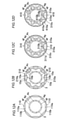
また、上記第1および第2実施形態では、磁極形成部10が、周方向に隣り合う一対の磁石挿入孔10aとブリッジ部10bとにより構成される例を示したが、本発明はこれに限られない。たとえば、図12Aおよび図13Aに示すように、磁極形成部110は、周方向に延びる1つの磁石挿入孔110aのみを含んでいる。この場合、周方向において隣り合う磁石挿入孔110a同士の間がブリッジ部110bとなる。図12Aに示すように、シャフト挿入孔4cの頂点4fは、全てのブリッジ部110bと周方向において重なる位置に配置される。また、図13Aに示すように、シャフト挿入孔14cの辺14gは、d軸(回転軸線Cから磁石挿入孔110aの周方向中央に向かう方向)と周方向において重なる位置に配置されている。
また、図12Bおよび図13Bに示すように、磁極形成部210は、一対の磁石挿入孔10aと、一対の磁石挿入孔10a同士の間のブリッジ部10bと、一対の磁石挿入孔10aの径方向外側において周方向に延びる磁石挿入孔210aとを含んでいる。図12Bに示すように、シャフト挿入孔4cの頂点4fは、全てのブリッジ部10bと周方向において重なる位置に配置される。また、図13Bに示すように、シャフト挿入孔14cの辺14gは、d軸(回転軸線Cからブリッジ部10bおよび磁石挿入孔210aの周方向中央に向かう方向)と周方向において重なる位置に配置されている。
また、図12Cおよび図13Cに示すように、磁極形成部310は、周方向に隣り合う一対の磁石挿入孔310aと、一対の磁石挿入孔310aの径方向外側において周方向に延びる磁石挿入孔311aとを含んでいる。磁石挿入孔310a同士の間のブリッジ部310bには、フラックスバリア310cが設けられている。図12Cに示すように、シャフト挿入孔4cの頂点4fは、全てのブリッジ部310b(フラックスバリア310c)と周方向において重なる位置に配置される。また、図13Cに示すように、シャフト挿入孔14cの辺14gは、d軸(回転軸線Cからブリッジ部310bおよび磁石挿入孔311aの周方向中央に向かう方向)と周方向において重なる位置に配置されている。
また、図12Dおよび図13Dに示すように、磁極形成部410は、一対の磁石挿入孔310aと、ブリッジ部310bと、一対の磁石挿入孔310aの径方向外側において周方向に隣り合うように設けられる一対の磁石挿入孔410aとを含んでいる。一対の磁石挿入孔410a同士の間にはブリッジ部410bが設けられている。図12Dに示すように、シャフト挿入孔4cの頂点4fは、全てのブリッジ部310b(ブリッジ部410b)と周方向において重なる位置に配置される。また、図13Dに示すように、シャフト挿入孔14cの辺14gは、d軸(回転軸線Cからブリッジ部310bおよびブリッジ部410bに向かう方向)と周方向において重なる位置に配置されている。
また、上記第1および第2実施形態では、ハイドロフォーミングを行った後に永久磁石5を磁石挿入孔10aに挿入する工程を行う例を示したが、本発明はこれに限られない。永久磁石5を磁石挿入孔10aに挿入した後にハイドロフォーミングを行ってもよい。
1、11 ロータ
3 シャフト
3e 外周面
4b、14b 積層コア
4c、14c シャフト挿入孔
4f、14f 頂点
4g、14g 辺
4h 径方向内側部分
4i、14i 内周面
4l 径方向外側部分
5 永久磁石
10、310、410 磁極形成部
10a、110a、210a、310a、311a、410a 磁石挿入孔
10b、110b、310b、410b ブリッジ部
800 液体
L2 距離(第1距離)
L3 距離(第2距離)
3 シャフト
3e 外周面
4b、14b 積層コア
4c、14c シャフト挿入孔
4f、14f 頂点
4g、14g 辺
4h 径方向内側部分
4i、14i 内周面
4l 径方向外側部分
5 永久磁石
10、310、410 磁極形成部
10a、110a、210a、310a、311a、410a 磁石挿入孔
10b、110b、310b、410b ブリッジ部
800 液体
L2 距離(第1距離)
L3 距離(第2距離)
Claims (5)
- 筒状のシャフトが挿入されるシャフト挿入孔と、永久磁石が挿入される磁石挿入孔とを含む積層コアを備えるロータの製造方法であって、
前記積層コアの軸方向から見て、前記積層コアの中央部に設けられるとともに複数の頂点を含む非円形形状を有する前記シャフト挿入孔の前記頂点と前記シャフトの外周面との距離が第1距離となるとともに、前記シャフトの前記外周面と前記シャフト挿入孔の辺との距離が前記第1距離よりも小さい第2距離となるように、前記シャフトを前記シャフト挿入孔に挿入する挿入工程と、
前記積層コアの前記シャフト挿入孔に前記シャフトが挿入された状態で、前記シャフトの内部に充填された液体が加圧されることによって膨張されるハイドロフォーミングにより、前記軸方向から見て前記シャフトの前記外周面を前記シャフト挿入孔の内周面に沿うように非円形形状に変形させることによって、前記シャフトを前記積層コアに固定する固定工程と、を備える、ロータの製造方法。 - 前記軸方向から見て、少なくとも一部の前記シャフト挿入孔の前記頂点が、周方向に隣り合う前記磁石挿入孔同士の間に設けられたブリッジ部と前記周方向に重なる位置に配置されるように、前記積層コアを形成する第1コア形成工程をさらに備える、請求項1に記載のロータの製造方法。
- 前記積層コアは、磁極を形成する磁極形成部を複数含み、
前記第1コア形成工程は、前記軸方向から見て、少なくとも一部の前記シャフト挿入孔の前記頂点が、前記複数の磁極形成部の各々において前記周方向に隣り合う一対の前記磁石挿入孔の前記磁石挿入孔同士の間に設けられ、前記積層コアの径方向外側部分と前記積層コアの径方向内側部分とを連結する前記ブリッジ部と、前記周方向に重なる位置に配置されるように、前記積層コアを形成する工程である、請求項2に記載のロータの製造方法。 - 前記軸方向から見て、前記シャフト挿入孔の辺が、周方向において前記積層コアのd軸と重なる位置に配置されるように、前記積層コアを形成する第2コア形成工程をさらに備える、請求項1に記載のロータの製造方法。
- 筒状のシャフトと、
永久磁石と、
前記シャフトが挿入されるシャフト挿入孔と、前記永久磁石が挿入される磁石挿入孔とを含む積層コアと、を備え、
前記シャフトは、前記シャフトの内部に充填された液体が加圧されることによって膨張されるハイドロフォーミングにより前記積層コアに固定されており、
前記シャフト挿入孔は、前記積層コアの軸方向から見て、前記積層コアの中央部に設けられるとともに、複数の頂点を含む非円形形状を有し、
前記積層コアは、前記シャフト挿入孔の前記頂点および辺の数が、極数の整数倍、または、極数を極数以外の極数の約数で除した数になるように構成されている、ロータ。
Priority Applications (4)
| Application Number | Priority Date | Filing Date | Title |
|---|---|---|---|
| JP2022536132A JP7452658B2 (ja) | 2020-07-16 | 2021-03-22 | ロータの製造方法およびロータ |
| US17/925,457 US20230188015A1 (en) | 2020-07-16 | 2021-03-22 | Method for manufacturing rotor and rotor |
| CN202180045536.3A CN115989623A (zh) | 2020-07-16 | 2021-03-22 | 转子的制造方法和转子 |
| EP21843279.7A EP4152576A4 (en) | 2020-07-16 | 2021-03-22 | ROTOR MANUFACTURING PROCESS AND ROTOR |
Applications Claiming Priority (2)
| Application Number | Priority Date | Filing Date | Title |
|---|---|---|---|
| JP2020121866 | 2020-07-16 | ||
| JP2020-121866 | 2020-07-16 |
Publications (1)
| Publication Number | Publication Date |
|---|---|
| WO2022014100A1 true WO2022014100A1 (ja) | 2022-01-20 |
Family
ID=79554675
Family Applications (1)
| Application Number | Title | Priority Date | Filing Date |
|---|---|---|---|
| PCT/JP2021/011728 Ceased WO2022014100A1 (ja) | 2020-07-16 | 2021-03-22 | ロータの製造方法およびロータ |
Country Status (5)
| Country | Link |
|---|---|
| US (1) | US20230188015A1 (ja) |
| EP (1) | EP4152576A4 (ja) |
| JP (1) | JP7452658B2 (ja) |
| CN (1) | CN115989623A (ja) |
| WO (1) | WO2022014100A1 (ja) |
Families Citing this family (1)
| Publication number | Priority date | Publication date | Assignee | Title |
|---|---|---|---|---|
| CN119973578B (zh) * | 2025-04-17 | 2025-07-25 | 东方电气集团东方电机有限公司 | 一种大尺寸薄壁筒成型方法 |
Citations (4)
| Publication number | Priority date | Publication date | Assignee | Title |
|---|---|---|---|---|
| JPS53149608A (en) * | 1978-05-18 | 1978-12-27 | Mitsubishi Electric Corp | Manufacture method of laminated iron core |
| JP2001268858A (ja) | 2000-03-17 | 2001-09-28 | Toyota Autom Loom Works Ltd | モータ用ロータ、電動圧縮機及びモータ用ロータの製造方法 |
| US20140097711A1 (en) * | 2012-10-05 | 2014-04-10 | Larry Kubes | One piece rotor hub/shaft for an electric machine and method |
| JP2019075877A (ja) * | 2017-10-13 | 2019-05-16 | トヨタ自動車株式会社 | 回転電機ロータの製造方法及び回転電機ロータ |
Family Cites Families (5)
| Publication number | Priority date | Publication date | Assignee | Title |
|---|---|---|---|---|
| DE10300148A1 (de) * | 2002-01-07 | 2003-08-28 | Arvinmeritor Technology Llc | Verfahren zur Herstellung einer Antriebswelle |
| JP5244721B2 (ja) * | 2009-07-07 | 2013-07-24 | トヨタ自動車株式会社 | 回転電機のロータ |
| KR101271950B1 (ko) * | 2011-12-26 | 2013-06-07 | 재단법인 포항산업과학연구원 | 중공형 모터축 및 이를 포함하는 모터장치 |
| DE102018122977B4 (de) * | 2018-09-19 | 2026-02-12 | Muhr Und Bender Kg | Wellenanordnung |
| DE102018218322A1 (de) * | 2018-10-26 | 2020-04-30 | Volkswagen Aktiengesellschaft | Verfahren und Werkzeug zur Herstellung eines Rotors für eine elektrische Maschine |
-
2021
- 2021-03-22 JP JP2022536132A patent/JP7452658B2/ja active Active
- 2021-03-22 CN CN202180045536.3A patent/CN115989623A/zh active Pending
- 2021-03-22 EP EP21843279.7A patent/EP4152576A4/en not_active Withdrawn
- 2021-03-22 WO PCT/JP2021/011728 patent/WO2022014100A1/ja not_active Ceased
- 2021-03-22 US US17/925,457 patent/US20230188015A1/en not_active Abandoned
Patent Citations (4)
| Publication number | Priority date | Publication date | Assignee | Title |
|---|---|---|---|---|
| JPS53149608A (en) * | 1978-05-18 | 1978-12-27 | Mitsubishi Electric Corp | Manufacture method of laminated iron core |
| JP2001268858A (ja) | 2000-03-17 | 2001-09-28 | Toyota Autom Loom Works Ltd | モータ用ロータ、電動圧縮機及びモータ用ロータの製造方法 |
| US20140097711A1 (en) * | 2012-10-05 | 2014-04-10 | Larry Kubes | One piece rotor hub/shaft for an electric machine and method |
| JP2019075877A (ja) * | 2017-10-13 | 2019-05-16 | トヨタ自動車株式会社 | 回転電機ロータの製造方法及び回転電機ロータ |
Non-Patent Citations (1)
| Title |
|---|
| See also references of EP4152576A4 |
Also Published As
| Publication number | Publication date |
|---|---|
| EP4152576A4 (en) | 2023-11-08 |
| CN115989623A (zh) | 2023-04-18 |
| US20230188015A1 (en) | 2023-06-15 |
| JP7452658B2 (ja) | 2024-03-19 |
| EP4152576A1 (en) | 2023-03-22 |
| JPWO2022014100A1 (ja) | 2022-01-20 |
Similar Documents
| Publication | Publication Date | Title |
|---|---|---|
| CN104937815B (zh) | 永磁体式旋转电机 | |
| JP6274475B2 (ja) | 回転子、回転電機および回転子の製造方法 | |
| US8878410B2 (en) | Rotor with reinforcing portions for an electric rotating machine | |
| JP7234333B2 (ja) | 2分節擬似ハルバッハモータの回転子 | |
| US12519353B2 (en) | Rotor core with plurality of permanent magnets and magnet holes with bridges between magnets/magnet holes | |
| CN103095088A (zh) | 旋转电机 | |
| WO2021060209A1 (ja) | 回転電機の回転子 | |
| WO2018131393A1 (ja) | 回転電機用ロータ | |
| US20230198324A1 (en) | Rotor for rotary electric machine | |
| JP2018198534A (ja) | 回転電機 | |
| US12519356B2 (en) | Rotor and rotating electric machine | |
| JP7452658B2 (ja) | ロータの製造方法およびロータ | |
| WO2019044206A1 (ja) | 回転電機 | |
| WO2023276680A1 (ja) | 回転電機 | |
| JP7528591B2 (ja) | ロータおよびロータの製造方法 | |
| US12573900B2 (en) | Rotor and rotating electric machine | |
| JP7718258B2 (ja) | ロータ及び回転電機 | |
| WO2024120543A1 (zh) | 电机转子和电机转子的制作方法 | |
| JP2014082836A (ja) | ロータと、それを備える回転電機 | |
| JP2022163299A (ja) | モータ | |
| US20250211042A1 (en) | Rotating electric machine core and rotating electric machine | |
| US20240186849A1 (en) | Rotor of rotary electric machine and method for manufacturing rotor | |
| JP4459886B2 (ja) | ステータおよびモータ | |
| JP2021078241A (ja) | ロータの製造方法およびロータ | |
| US20240097512A1 (en) | Rotor and rotating electric machine |
Legal Events
| Date | Code | Title | Description |
|---|---|---|---|
| 121 | Ep: the epo has been informed by wipo that ep was designated in this application |
Ref document number: 21843279 Country of ref document: EP Kind code of ref document: A1 |
|
| ENP | Entry into the national phase |
Ref document number: 2022536132 Country of ref document: JP Kind code of ref document: A |
|
| ENP | Entry into the national phase |
Ref document number: 2021843279 Country of ref document: EP Effective date: 20221213 |
|
| NENP | Non-entry into the national phase |
Ref country code: DE |