WO2022014243A1 - 水電解セルの電極触媒、水電解セル、及び水電解装置 - Google Patents
水電解セルの電極触媒、水電解セル、及び水電解装置 Download PDFInfo
- Publication number
- WO2022014243A1 WO2022014243A1 PCT/JP2021/022953 JP2021022953W WO2022014243A1 WO 2022014243 A1 WO2022014243 A1 WO 2022014243A1 JP 2021022953 W JP2021022953 W JP 2021022953W WO 2022014243 A1 WO2022014243 A1 WO 2022014243A1
- Authority
- WO
- WIPO (PCT)
- Prior art keywords
- water electrolysis
- electrolysis cell
- electrode catalyst
- catalyst
- anode
- Prior art date
- Legal status (The legal status is an assumption and is not a legal conclusion. Google has not performed a legal analysis and makes no representation as to the accuracy of the status listed.)
- Ceased
Links
Images



Classifications
-
- B—PERFORMING OPERATIONS; TRANSPORTING
- B01—PHYSICAL OR CHEMICAL PROCESSES OR APPARATUS IN GENERAL
- B01J—CHEMICAL OR PHYSICAL PROCESSES, e.g. CATALYSIS OR COLLOID CHEMISTRY; THEIR RELEVANT APPARATUS
- B01J23/00—Catalysts comprising metals or metal oxides or hydroxides, not provided for in group B01J21/00
- B01J23/38—Catalysts comprising metals or metal oxides or hydroxides, not provided for in group B01J21/00 of noble metals
- B01J23/40—Catalysts comprising metals or metal oxides or hydroxides, not provided for in group B01J21/00 of noble metals of the platinum group metals
- B01J23/46—Ruthenium, rhodium, osmium or iridium
-
- B—PERFORMING OPERATIONS; TRANSPORTING
- B01—PHYSICAL OR CHEMICAL PROCESSES OR APPARATUS IN GENERAL
- B01J—CHEMICAL OR PHYSICAL PROCESSES, e.g. CATALYSIS OR COLLOID CHEMISTRY; THEIR RELEVANT APPARATUS
- B01J23/00—Catalysts comprising metals or metal oxides or hydroxides, not provided for in group B01J21/00
- B01J23/70—Catalysts comprising metals or metal oxides or hydroxides, not provided for in group B01J21/00 of the iron group metals or copper
- B01J23/74—Iron group metals
- B01J23/75—Cobalt
-
- B—PERFORMING OPERATIONS; TRANSPORTING
- B01—PHYSICAL OR CHEMICAL PROCESSES OR APPARATUS IN GENERAL
- B01J—CHEMICAL OR PHYSICAL PROCESSES, e.g. CATALYSIS OR COLLOID CHEMISTRY; THEIR RELEVANT APPARATUS
- B01J35/00—Catalysts, in general, characterised by their form or physical properties
- B01J35/60—Catalysts, in general, characterised by their form or physical properties characterised by their surface properties or porosity
-
- C—CHEMISTRY; METALLURGY
- C01—INORGANIC CHEMISTRY
- C01B—NON-METALLIC ELEMENTS; COMPOUNDS THEREOF; METALLOIDS OR COMPOUNDS THEREOF NOT COVERED BY SUBCLASS C01C
- C01B3/00—Hydrogen; Gaseous mixtures containing hydrogen; Separation of hydrogen from mixtures containing it; Purification of hydrogen; Reversible storage of hydrogen
- C01B3/02—Production of hydrogen; Production of gaseous mixtures containing hydrogen
-
- C—CHEMISTRY; METALLURGY
- C25—ELECTROLYTIC OR ELECTROPHORETIC PROCESSES; APPARATUS THEREFOR
- C25B—ELECTROLYTIC OR ELECTROPHORETIC PROCESSES FOR THE PRODUCTION OF COMPOUNDS OR NON-METALS; APPARATUS THEREFOR
- C25B1/00—Electrolytic production of inorganic compounds or non-metals
- C25B1/01—Products
- C25B1/02—Hydrogen or oxygen
- C25B1/04—Hydrogen or oxygen by electrolysis of water
-
- C—CHEMISTRY; METALLURGY
- C25—ELECTROLYTIC OR ELECTROPHORETIC PROCESSES; APPARATUS THEREFOR
- C25B—ELECTROLYTIC OR ELECTROPHORETIC PROCESSES FOR THE PRODUCTION OF COMPOUNDS OR NON-METALS; APPARATUS THEREFOR
- C25B11/00—Electrodes; Manufacture thereof not otherwise provided for
- C25B11/04—Electrodes; Manufacture thereof not otherwise provided for characterised by the material
-
- C—CHEMISTRY; METALLURGY
- C25—ELECTROLYTIC OR ELECTROPHORETIC PROCESSES; APPARATUS THEREFOR
- C25B—ELECTROLYTIC OR ELECTROPHORETIC PROCESSES FOR THE PRODUCTION OF COMPOUNDS OR NON-METALS; APPARATUS THEREFOR
- C25B11/00—Electrodes; Manufacture thereof not otherwise provided for
- C25B11/04—Electrodes; Manufacture thereof not otherwise provided for characterised by the material
- C25B11/051—Electrodes formed of electrocatalysts on a substrate or carrier
- C25B11/054—Electrodes comprising electrocatalysts supported on a carrier
-
- C—CHEMISTRY; METALLURGY
- C25—ELECTROLYTIC OR ELECTROPHORETIC PROCESSES; APPARATUS THEREFOR
- C25B—ELECTROLYTIC OR ELECTROPHORETIC PROCESSES FOR THE PRODUCTION OF COMPOUNDS OR NON-METALS; APPARATUS THEREFOR
- C25B11/00—Electrodes; Manufacture thereof not otherwise provided for
- C25B11/04—Electrodes; Manufacture thereof not otherwise provided for characterised by the material
- C25B11/051—Electrodes formed of electrocatalysts on a substrate or carrier
- C25B11/073—Electrodes formed of electrocatalysts on a substrate or carrier characterised by the electrocatalyst material
-
- C—CHEMISTRY; METALLURGY
- C25—ELECTROLYTIC OR ELECTROPHORETIC PROCESSES; APPARATUS THEREFOR
- C25B—ELECTROLYTIC OR ELECTROPHORETIC PROCESSES FOR THE PRODUCTION OF COMPOUNDS OR NON-METALS; APPARATUS THEREFOR
- C25B11/00—Electrodes; Manufacture thereof not otherwise provided for
- C25B11/04—Electrodes; Manufacture thereof not otherwise provided for characterised by the material
- C25B11/051—Electrodes formed of electrocatalysts on a substrate or carrier
- C25B11/073—Electrodes formed of electrocatalysts on a substrate or carrier characterised by the electrocatalyst material
- C25B11/075—Electrodes formed of electrocatalysts on a substrate or carrier characterised by the electrocatalyst material consisting of a single catalytic element or catalytic compound
- C25B11/085—Organic compound
-
- C—CHEMISTRY; METALLURGY
- C25—ELECTROLYTIC OR ELECTROPHORETIC PROCESSES; APPARATUS THEREFOR
- C25B—ELECTROLYTIC OR ELECTROPHORETIC PROCESSES FOR THE PRODUCTION OF COMPOUNDS OR NON-METALS; APPARATUS THEREFOR
- C25B9/00—Cells or assemblies of cells; Constructional parts of cells; Assemblies of constructional parts, e.g. electrode-diaphragm assemblies; Process-related cell features
-
- Y—GENERAL TAGGING OF NEW TECHNOLOGICAL DEVELOPMENTS; GENERAL TAGGING OF CROSS-SECTIONAL TECHNOLOGIES SPANNING OVER SEVERAL SECTIONS OF THE IPC; TECHNICAL SUBJECTS COVERED BY FORMER USPC CROSS-REFERENCE ART COLLECTIONS [XRACs] AND DIGESTS
- Y02—TECHNOLOGIES OR APPLICATIONS FOR MITIGATION OR ADAPTATION AGAINST CLIMATE CHANGE
- Y02E—REDUCTION OF GREENHOUSE GAS [GHG] EMISSIONS, RELATED TO ENERGY GENERATION, TRANSMISSION OR DISTRIBUTION
- Y02E60/00—Enabling technologies; Technologies with a potential or indirect contribution to GHG emissions mitigation
- Y02E60/30—Hydrogen technology
- Y02E60/36—Hydrogen production from non-carbon containing sources, e.g. by water electrolysis
Definitions
- the present disclosure relates to an electrode catalyst of a water electrolysis cell, a water electrolysis cell, and a water electrolysis device.
- Patent Document 1 discloses a polymer having a Tröger basic skeleton.
- Patent Document 2 discloses a polymer having a spirobiindane skeleton.
- Patent Document 3 discloses a polymer film containing an imide group.
- Non-Patent Document 1 discloses a membrane containing Polymers of Intrinsic Microporosity (PIM).
- Non-Patent Document 2 discloses a porous polymer having a Tröger base.
- the present disclosure provides an electrode catalyst for a water electrolytic cell having a low overvoltage.
- One aspect of the disclosure is with the catalyst With a neutral intrinsic microporous polymer, Provided is an electrode catalyst for a water electrolysis cell.
- an electrode catalyst for a water electrolytic cell having a low overvoltage can be provided.
- FIG. 1 is a diagram schematically showing an electrode catalyst of the water electrolysis cell according to the first embodiment.
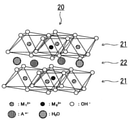
- FIG. 2 is a diagram schematically showing an example of the crystal structure of layered double hydride (LDH).
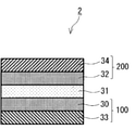
- FIG. 3 is a cross-sectional view schematically showing an example of the water electrolysis cell according to the second embodiment.
- FIG. 4 is a cross-sectional view schematically showing an example of the water electrolyzer according to the third embodiment.
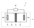
- FIG. 5 is a cross-sectional view schematically showing another example of the water electrolysis cell according to the fourth embodiment.
- FIG. 6 is a cross-sectional view schematically showing another example of the water electrolyzer according to the fifth embodiment.
- electrolysis of water can be used as a method for producing hydrogen from surplus electricity.
- the electrolysis of water is also called water electrolysis.
- a major component of a water electrolyzer includes a membrane electrode assembly (MEA) consisting of a gas diffusion layer, a catalyst, and an electrolyte membrane.
- MEA membrane electrode assembly
- an organic material may be used in order to improve the dispersibility of the catalyst material and / or to improve the binding force to the substrate such as an electrode. By using an organic material, the dispersibility of the catalyst material can be improved and the bonding force to the substrate can be improved.
- the electrical resistance of the organic material is large, and the organic material covers the active site on the surface of the catalyst, so that the overvoltage can increase when a voltage is applied. Therefore, it is important to provide an electrode catalyst capable of reducing the loss due to the overvoltage of the electrode even when an organic material is used. Therefore, the present inventors have made extensive studies on a material that can suppress the area covering the catalyst. As a result, it was newly found that the use of the intrinsic microporous polymer (PIM) is advantageous in reducing the overvoltage of the electrode catalyst of the water electrolysis cell.
- PIM intrinsic microporous polymer
- the present inventors have found the following novel electrode catalysts for water electrolysis cells.
- the electrode catalyst of the water electrolysis cell according to the first aspect of the present disclosure is With the catalyst It comprises a neutral intrinsic microporous polymer.
- an electrode catalyst of a water electrolytic cell having a low overvoltage can be provided.
- the intrinsic microporous polymer may have a Tröger basic skeleton.
- the intrinsic microporous polymer may have a spirobindan skeleton.
- the intrinsic microporous polymer may have a polyimide skeleton.
- the electrode catalyst of the water electrolysis cell can suppress an increase in overvoltage.
- the water electrolysis cell according to the fifth aspect of the present disclosure is With the anode, With the cathode An electrolyte membrane arranged between the anode and the cathode, Equipped with At least one selected from the group consisting of the anode and the cathode comprises an electrode catalyst according to any one of the first to fourth aspects.
- the water electrolysis cell can suppress an increase in overvoltage.
- the electrolyte membrane may include a proton exchange membrane.
- the electrolyte membrane may include an anion exchange membrane.
- the water electrolysis cell according to the eighth aspect of the present disclosure is The diaphragm that separates the first space and the second space, With the anode provided in the first space, With the cathode provided in the second space, Equipped with At least one selected from the group consisting of the anode and the cathode comprises an electrode catalyst according to any one of the first to fourth aspects.
- the water electrolysis cell can suppress an increase in overvoltage.
- the water electrolyzer according to the ninth aspect of the present disclosure is The water electrolysis cell according to any one of the fifth to eighth aspects, and A voltage applyer connected to the anode and the cathode and applying a voltage between the anode and the cathode. To prepare for.
- the water electrolyzer can suppress an increase in overvoltage.
- FIG. 1 is a diagram schematically showing an electrode catalyst of a water electrolysis cell according to the present embodiment.
- the electrode catalyst 1 according to the present embodiment includes a catalyst 10 and a neutral intrinsic microporous polymer (PIM) 11.
- PIM neutral intrinsic microporous polymer
- the PIM 11 is present on at least a portion of the surface of the catalyst 10. According to such a configuration, even if the PIM 11 is present on the surface of the catalyst 10, the area of the exposed surface of the catalyst 10 is unlikely to be small, and the decrease in the catalytic activity of the electrode catalyst 1 can be suppressed. Therefore, when a voltage is applied to the electrode catalyst 1, an increase in overvoltage can be suppressed. That is, the electrode catalyst 1 may have a low overvoltage.
- the intrinsic microporous polymer (PIM) 11 is typically an organic polymer having a particular molecular structure and inherent microporousness.
- PIM11 is neutral.
- neutral is meant that the molecule is free of anion and cation exchange groups.
- An example of an anion exchange group is a quaternary ammonium group.
- An example of a cation exchange group is a sulfonic acid ion group.
- PIM 11 may be present on at least a portion of the surface of catalyst 10.
- PIM 11 can also be present, for example, in the substrate on which the electrode catalyst 1 is formed.
- PIM 11 can also be present on the surface of the substrate. Since the electrode catalyst 1 contains the PIM 11, the bonding force between the substrate and the catalyst 10 can be improved when the electrode catalyst 1 is formed on the substrate. Thereby, the electrode catalyst 1 having high durability can be provided.
- the PIM 11 may play a role of dispersing the electrode catalysts 1 with each other.
- the inclusion of PIM 11 in the electrode catalyst 1 can prevent the electrode catalysts 1 from aggregating with each other.
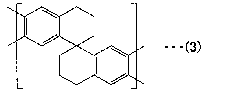
- the molecular structure of PIM11 is not limited to a specific molecular structure. Examples of its molecular structure are the Tröger basic skeleton, the spirobindan skeleton, and the polyimide skeleton.
- the Tröger basic skeleton has, for example, a bicyclic compound, and the bicyclic compound contains two bridgehead nitrogen atoms. Nitrogen atoms form a chiral center.
- the Tröger basic skeleton may further have an ethanoanthracene skeleton and a triptycene skeleton. Specifically, the Tröger basic skeleton has a molecular structure represented by the following general formula (1).
- L represents a linker.
- the linker L is not limited to a specific structure.
- the linker L includes, for example, an aromatic ring, a spirovinedan skeleton, an ethanoanthracene skeleton, and a triptycene skeleton.
- the spirobiindane skeleton has, for example, two indanes.
- the two indanes form a spiro compound bonded by a spiro atom center.
- the spiro compound means a bicyclic organic compound, and one of the atoms constituting the ring is shared with another ring. This atom is called a spiro atom.
- indane includes, for example, a benzene ring bonded to a five-membered ring containing a spiro atom or a benzene ring bonded to a six-membered ring containing a spiro atom.
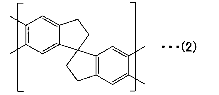
- the spirobindan skeleton has a molecular structure represented by the following general formula (2) or (3).
- the polyimide skeleton is formed, for example, by polycondensation of acid anhydride and diamine.
- the acid anhydride and diamine may further contain a spirovinedan skeleton, an ethanoanthracene skeleton, and a triptycene skeleton.
- the polyimide skeleton has, for example, a molecular structure represented by the following general formula (4).
- L represents a linker.
- the linker L is not limited to a specific structure.
- the linker L includes, for example, an aromatic ring, a spirovinedan skeleton, an ethanoanthracene skeleton, and a triptycene skeleton.
- Examples of PIM11 are an organic polymer having a tracer basic skeleton, an organic polymer having a spirobiindan skeleton, and an organic polymer having a polyimide skeleton.
- the specific molecular structure of PIM 11 may include at least one selected from the group consisting of Tröger's basic skeleton, spirobiindan skeleton, and polyimide skeleton. These skeletons may have inherent microporosity. In addition, these skeletons can be skeletons with high rigidity. By including these skeletons in the molecular structure, PIM11 may have the desired porosity. PIM11 may have these skeletons in the main chain or in the side chain.
- the PIM 11 may have a Tröger's base skeleton, a spirovinedan skeleton, and a polyimide skeleton, and may further have other substituents.
- substituents are halogen group, hydroxy group, alkyl group, alkoxy group, carboxy group, ester group, acyl group, amino group, nitro group, sulfo group, and aryl group.
- halogen groups are fluoro, chloro, and bromo groups.
- PIM11 may contain at least one selected from the group consisting of an organic polymer having a tracer basic skeleton, an organic polymer having a spirobindan skeleton, and an organic polymer having a polyimide skeleton.
- the average pore diameter of PIM11 is, for example, 4 nm or less.
- the average pore diameter of PIM11 can be measured by Brunauer-Emmett-Teller (BET) method, which is N 2 gas adsorption method.
- BET Brunauer-Emmett-Teller
- the average pore diameter of PIM11 can be measured, for example, as follows. A sample containing PIM11 is degassed under reduced pressure at 100 ° C. for 15 hours using a pore distribution measuring device VacPrep 061 manufactured by Shimadzu Corporation-Micromeritics. After that, the average pore diameter of PIM11 can be calculated by performing pore distribution analysis by the N 2 gas adsorption method using the automatic specific surface area measuring device Tristar II 3020 manufactured by Shimadzu Corporation-Micromeritics.
- the catalyst 10 is a material having activity in the anode or cathode of the water electrolysis cell against the production reaction of gases such as hydrogen and oxygen.
- Examples of catalyst 10 are metals and metal oxides.
- An example of a metal is Pt.
- Examples of metal oxides are layered double hydroxides (LDH) and IrO x .
- LDH contains, for example, two or more transition metals.
- the transition metal comprises, for example, at least two selected from the group consisting of V, Cr, Mn, Fe, Co, Ni, Cu, W, and Ru.
- LDH has, for example, a composition represented by the following composition formula (1).
- M 1 2+ is a divalent transition metal ion.
- M 2 3+ is a trivalent transition metal ion.
- An - is an anion between layers.
- x is a rational number satisfying the condition of 0 ⁇ x ⁇ 1.
- y is a number corresponding to the required amount of charge balance.
- n is an integer.
- m is an appropriate rational number.
- LDH may contain Ni and Fe.
- M 1 may be Ni and M 2 may be Fe. That is, the transition metal elements contained in LDH may be Ni and Fe. According to such a configuration, the electrode catalyst 1 may have higher catalytic activity.
- the ratio of the amount of substance of Fe to the total amount of substance of Ni and Fe contained in LDH may be 0.25 or more and 0.5 or less. According to such a configuration, the electrode catalyst 1 may have higher catalytic activity.
- LDH may contain a chelating agent.
- the chelating agent may be coordinated to the transition metal ion in LDH.
- the dispersion stability of LDH can be further improved.
- LDH contains a chelating agent, LDH having a small particle size can be synthesized. As a result, the surface area of LDH can be improved, so that the catalytic activity can be improved.
- the average particle size of LDH may be 100 nm or less, or 50 nm or less. Further, the average particle size of LDH may be 10 nm or less.
- the average particle size of LDH is the area of the two-dimensional distribution map when the particle size distribution of LDH obtained by the small-angle X-ray scattering method (SAXS) is represented by a two-dimensional distribution map showing the relationship between the particle size and the distribution. It is the value divided by the total number of particles.
- the distribution means a numerical value proportional to the total volume occupied by the number of particles of the particle size.
- the area of the two-dimensional distribution map is, for example, the product of the particle size and the number of particles corresponding to the particle size.
- the chelating agent is not limited to a specific chelating agent.
- the chelating agent is, for example, an organic compound coordinated to a transition metal in LDH.
- the chelating agent may be at least one selected from the bidentate organic ligand and the tridentate organic ligand.
- Examples of chelating agents are ⁇ -diketone, ⁇ -ketoester, and hydroxycarboxylic acids.
- Examples of ⁇ -diketones are acetylacetone (ACAC), trifluoroacetylacetone, hexafluoroacetylacetone, benzoylacetone, thenoyltrifluoroacetone, dipyrrobic methane, dibenzoylmethane, and ascorbic acid.
- ⁇ -ketoesters are methyl acetoacetic acid, ethyl acetoacetate, allyl acetoacetic acid, benzyl acetoacetic acid, acetoacetic acid-n-propyl, acetoacetic acid-iso-propyl, acetoacetic acid-n-butyl, acetoacetic acid-iso-butyl. , Acetoacetic acid-tert-butyl, acetoacetic acid-2-methoxyethyl, and methyl 3-oxopentanoate.
- hydroxycarboxylic acids and salts thereof are tartrate acid, citric acid, malic acid, gluconic acid, ferulic acid, lactic acid, glucuronic acid, and salts thereof.
- the chelating agent may contain at least one selected from the group consisting of acetylacetone and trisodium citrate.
- the chelating agent may be at least one selected from acetylacetone and trisodium citrate.
- An- is an interlayer ion.
- An- is an inorganic ion or an organic ion. Examples of inorganic ion, CO 3 2-, NO 3 - , Cl -, SO 4 2-, Br -, OH -, F -, I -, Si 2 O 5 2-, B 4 O 5 (OH) 4 2- and PO 4 3- . Examples of the organic ions, CH 3 (CH 2) n SO 4-, CH 3 (CH 2) n COO -, CH 3 (CH 2) n PO 4-, and CH 3 (CH 2) n NO 3- in be.
- An - is an anion inserted between layers of metal hydroxide with water molecules. The An - charge and ion magnitude are not limited to any particular value. LDH may contain one type of An- or may contain a plurality of types of An- .
- FIG. 2 is a diagram schematically showing an example of the crystal structure of LDH represented by the composition formula (1).
- LDH 20 has OH- ions at each vertex of an octahedron centered on M 1 2+ or M 2 3+.
- Metal hydroxides are represented by [M 1 2 + 1-x M 2 3+ x (OH) 2 ] x + .
- the metal hydroxide has a layered structure in which hydroxide octahedrons share a ridge and are connected in two dimensions. Anions and water molecules are located between the layers of metal hydroxide.
- the layer of metal hydroxide functions as a host layer 21, and anions and water molecules are inserted as a guest layer 22.
- the LDH 20 has a sheet-like structure in which a host layer 21 of a metal hydroxide and a guest layer 22 of anions and water molecules are alternately laminated.
- the LDH 20 has a structure in which a part of M 1 2+ contained in the layer of the metal hydroxide is replaced with M 2 3+. Therefore, the surface of the LDH 20 is usually positively charged.
- the electrode catalyst 1 may further contain a carrier. According to such a configuration, since the catalyst 10 is stably arranged by the carrier with respect to the catalyst 10, the catalytic activity of the electrode catalyst 1 is likely to be kept high.
- the carrier is typically conductive.
- the carrier is not limited to a particular material.
- Examples of carriers are transition metals and carbon materials.
- Examples of transition metals are V, Cr, Mn, Fe, Co, Ni, Cu, W, and Ru.
- Examples of carbon materials are acetylene black and ketchen black (KB).
- the shape of the carrier is not limited to a specific shape.
- the shape of the carrier may be in the form of foam or in the form of particles.
- the electrode catalyst 1 according to the present embodiment is used, for example, in a proton exchange membrane type water electrolyzer, an anion exchange membrane type water electrolyzer, or an alkaline diaphragm type water electrolyzer.
- the electrode catalyst 1 can be used for at least one selected from an anode and a cathode in the above-mentioned water electrolyzer.
- FIG. 3 is a cross-sectional view schematically showing an example of the water electrolysis cell according to the present embodiment.
- the water electrolysis cell 2 includes an electrolyte membrane 31, an anode 100, and a cathode 200.
- the electrolyte membrane 31 is arranged, for example, between the anode 100 and the cathode 200. At least one selected from the anode 100 and the cathode 200 includes the electrode catalyst 1 described in the first embodiment.
- the electrolyte membrane 31 may be an electrolyte membrane having ionic conductivity.
- the electrolyte membrane 31 is not limited to a specific type.
- the electrolyte membrane 31 may include a proton exchange membrane.
- the electrolyte membrane 31 may be a proton exchange membrane.
- the electrolyte membrane 31 may include an anion exchange membrane.
- the electrolyte membrane 31 may be an anion exchange membrane.
- the electrolyte membrane 31 is configured so that the oxygen gas generated at the anode 100 and the hydrogen gas generated at the cathode 200 are difficult to mix.
- the anode 100 includes, for example, the catalyst layer 30.
- the catalyst layer 30 may be provided on one main surface of the electrolyte membrane 31.
- the "main surface” means the surface having the largest area of the electrolyte membrane 31.
- the electrode catalyst contained in the catalyst layer 30 may be the electrode catalyst 1 of the first embodiment.
- the anode 100 may be further provided with a porous and conductive gas diffusion layer 33 on the catalyst layer 30.
- the cathode 200 includes, for example, a catalyst layer 32.
- the catalyst layer 32 may be provided on the other main surface of the electrolyte membrane 31. That is, the catalyst layer 32 may be provided on the main surface of the electrolyte membrane 31 on the side opposite to the main surface on which the catalyst layer 30 is provided.
- the catalyst metal that can be used for the catalyst layer 32 is not limited to a specific type.
- the electrode catalyst may be platinum or the electrode catalyst 1.
- the cathode 200 may be further provided with a porous and conductive gas diffusion layer 34 on top of the catalyst layer 32.
- the water electrolysis cell 2 can suppress an increase in overvoltage.
- FIG. 4 is a cross-sectional view schematically showing an example of the water electrolyzer according to the present embodiment.
- the water electrolyzer 3 includes a water electrolyzer cell 2 and a voltage adapter 40. Since the water electrolysis cell 2 is the same as the water electrolysis cell 2 of the second embodiment, the description thereof will be omitted.
- the voltage applyer 40 is connected to the anode 100 and the cathode 200 of the water electrolysis cell 2.
- the voltage applyer 40 is a device that applies a voltage to the anode 100 and the cathode 200 of the water electrolysis cell 2.
- the voltage applyer 40 increases the potential at the anode 100 and decreases the potential at the cathode 200.
- the voltage applyer 40 is not limited to a specific type as long as a voltage can be applied between the anode 100 and the cathode 200.
- the voltage applyer 40 may be a device that adjusts the voltage applied between the anode 100 and the cathode 200. Specifically, when the voltage applyer 40 is connected to a DC power source such as a battery, a solar cell, or a fuel cell, the voltage applyer 40 includes a DC / DC converter. When the voltage applyer 40 is connected to an AC power source such as a commercial power source, the voltage applyer 40 includes an AC / DC converter.
- the voltage adapter 40 adjusts the voltage applied between the anode 100 and the cathode 200 and the current flowing between the anode 100 and the cathode 200 so that the electric power supplied to the water electrolyzer 3 becomes a predetermined set value. It may be a power supply type power supply.
- the water electrolyzer 3 can suppress an increase in overvoltage.
- FIG. 5 is a cross-sectional view schematically showing another example of the water electrolysis cell according to the present embodiment.
- the water electrolysis cell according to the present embodiment is, for example, an alkaline water electrolysis cell 4 using an alkaline aqueous solution.
- an alkaline aqueous solution is used.
- the alkaline aqueous solution are a potassium hydroxide aqueous solution and a sodium hydroxide aqueous solution.
- the alkaline water electrolysis cell 4 includes an anode 300 and a cathode 400.
- the alkaline water electrolysis cell 4 further includes an electrolytic cell 70, a first space 50, and a second space 60.
- the anode 300 is provided in the first space 50.
- the cathode 400 is provided in the second space 60.
- the alkaline water electrolysis cell 4 has a diaphragm 41.
- the diaphragm 41 is provided inside the electrolytic cell 70, and separates the first space 50 and the second space 60.
- At least one selected from the anode 300 and the cathode 400 includes an electrode catalyst 1.
- the anode 300 may contain the electrode catalyst 1.
- the anode 300 may include, for example, a catalyst layer, and the catalyst layer may contain the electrode catalyst 1.
- the cathode 400 may contain the electrode catalyst 1.
- the cathode 400 may include, for example, a catalyst layer, and the catalyst layer may contain the electrode catalyst 1.
- the diaphragm 41 is, for example, a diaphragm for alkaline water electrolysis.
- the anode 300 may be arranged in contact with the diaphragm 41, or may have a gap between the anode 300 and the diaphragm 41.
- the cathode 400 may be arranged in contact with the diaphragm 41, or may have a gap between the cathode 400 and the diaphragm 41.
- the alkaline water electrolysis cell 4 electrolyzes an alkaline aqueous solution to produce hydrogen and oxygen.
- An aqueous solution containing a hydroxide of an alkali metal or an alkaline earth metal can be supplied to the first space 50 of the alkaline water electrolysis cell 4.
- An alkaline aqueous solution can be supplied to the second space 60 of the alkaline water electrolysis cell 4. Hydrogen and oxygen are produced by electrolyzing while discharging an alkaline aqueous solution having a predetermined concentration from the first space 50 and the second space 60.
- the alkaline water electrolysis cell 4 can suppress an increase in overvoltage.
- FIG. 6 is a cross-sectional view schematically showing another example of the water electrolyzer according to the present embodiment.
- the water electrolyzer according to the present embodiment is, for example, an alkaline water electrolyzer 5 using an alkaline aqueous solution.
- the alkaline water electrolyzer 5 includes an alkaline water electrolyzer cell 4 and a voltage adapter 40. Since the alkaline water electrolysis cell 4 is the same as the alkaline water electrolysis cell 4 of the fourth embodiment, the description thereof will be omitted.
- the voltage applyer 40 is connected to the anode 300 and the cathode 400 of the alkaline water electrolysis cell 4.
- the voltage applyer 40 is a device that applies a voltage to the anode 300 and the cathode 400 of the alkaline water electrolysis cell 4.
- the alkaline water electrolyzer 5 can suppress an increase in overvoltage.
- Example 1 Preparation of Ni-Fe LDH supported on Ni carrier
- a mixture containing Ni—Fe LDH and Ni particles was prepared as follows. First, a mixed solvent of water and ethanol (manufactured by Fujifilm Wako Pure Chemical Industries, Ltd., special grade reagent) was prepared. The volume ratio of water and ethanol was 2: 3. Nickel chloride hexahydrate (manufactured by Fuji Film Wako Junyaku Co., Ltd.) and iron chloride hexahydrate (manufactured by Fuji Film Wako Junyaku Co., Ltd.) are added to this mixed solvent, and the total concentration of Ni ions and Fe ions is 1.0 M.
- the solvent was dissolved so that the ratio of the amount of substance of Fe ion to the total amount of substance of Ni ion and Fe ion was 0.33.
- M means mol / dm 3 .
- acetylacetone (ACAC) was added as a chelating agent so as to have a substance amount of one-third of the total substance amount of Ni ion and Fe ion.
- the resulting solution was stirred for 30 minutes.
- Ni particles manufactured by US Research Nanomaterials, Inc., particle size: 40 nm
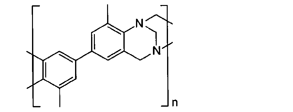
- PIM (1) according to Example 1 was prepared with reference to Non-Patent Document 2.
- An equal amount of 4,4'-diamino-3,3'-dimethylbiphenyl was dissolved in an equal amount of 5 mol of dimethoxymethane.
- the solution was cooled to 0 ° C.
- an equal amount of 120 mol of trifluoroacetic acid was added dropwise to this solution over 0.5 hours.
- the mixed solution was stirred at room temperature for 5 days.
- this mixed solution was added to a vigorously stirred aqueous solution of ammonium hydroxide, and the mixture was allowed to stand for 2 hours.
- the solid thus obtained was collected by filtration and washed with water, methanol and acetone in this order.
- PIM (1) is an organic polymer represented by the following structural formula.
- PIM (1) is an organic polymer having a Tröger basic skeleton.
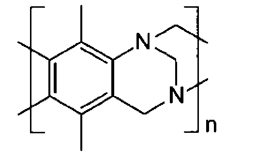
- Example 2 A sample for evaluating the catalytic activity according to Example 2 was obtained in the same manner as in Example 1 except that PIM (2) was used instead of PIM (1) as the organic binder.
- PIM (2) is an organic polymer represented by the following structural formula.
- PIM (2) is an organic polymer having a Tröger basic skeleton.
- Example 3 A sample for evaluating the catalytic activity according to Example 3 was obtained in the same manner as in Example 1 except that PIM (3) was used instead of PIM (1) as the organic binder.
- PIM (3) is an organic polymer represented by the following structural formula.
- PIM (3) is an organic polymer having a Tröger basic skeleton.
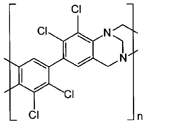
- Example 4 A sample for evaluating the catalytic activity according to Example 4 was obtained in the same manner as in Example 1 except that PIM (4) was used instead of PIM (1) as the organic binder.
- PIM (4) is an organic polymer represented by the following structural formula.
- PIM (4) is an organic polymer having a Tröger basic skeleton.
- Ni-Fe LDH was prepared as follows. First, a mixed solvent of water and ethanol (manufactured by Fujifilm Wako Pure Chemical Industries, Ltd., special grade reagent) was prepared. The volume ratio of water and ethanol was 2: 3. Nickel chloride hexahydrate (manufactured by Fuji Film Wako Junyaku Co., Ltd.) and iron chloride hexahydrate (manufactured by Fuji Film Wako Junyaku Co., Ltd.) are added to this mixed solvent, and the total concentration of Ni ions and Fe ions is 1.0 M.
- the solvent was dissolved so that the ratio of the amount of substance of Fe ion to the total amount of substance of Ni ion and Fe ion was 0.33.
- M means mol / dm 3 .
- acetylacetone (ACAC) was added as a chelating agent so as to have a substance amount of one-third of the total substance amount of Ni ion and Fe ion.
- the resulting solution was stirred for 30 minutes.
- propylene oxide (POX) was added as a pH increasing agent so as to be twice the amount of the substance of chloride ion in the solution, and the mixture was stirred for 1 minute. At this time, POX gradually captures hydrogen ions in the solution, so that the pH of the solution gradually rises.
- LDH of the target sample was collected.
- the above LDH preparation method is an example and is not limited to this example.
- the particle size distribution of Ni—Fe LDH dispersed in the solution was obtained according to the small-angle X-ray scattering method (SAXS) using a Smart Lab manufactured by Rigaku.
- SAXS small-angle X-ray scattering method
- the relationship between the obtained particle size and the distribution was represented by a two-dimensional distribution map, and the area of the two-dimensional distribution map was divided by the total number of particles to determine the average particle size of LDH.
- the average particle size of Ni—Fe LDH was 10 nm.
- Ketjen Black EC600JD manufactured by Lion Specialty Chemicals Co., Ltd. has a mass ratio of Ni-Fe LDH: Ketjen Black 2: 1 and a total mass of 8.5 mg.
- Ni-Fe LDH supported on a Ketjen black carrier Ni-Fe LDH supported on a Ketjen black carrier.
- Example 5 a sample for evaluating the catalytic activity according to Example 5 was obtained in the same manner as in Example 1 except that Ni-Fe LDH supported on the Ketjen black carrier was used.
- Example 6 Instead of the mixture of Ni-Fe LDH and Ni particles, IrO x SA100 manufactured by Tanaka Kikinzoku Co., Ltd. was used, and the mass ratio of IrO x and PIM (1) was 5: 1 and the total mass was 6 mg. A sample for evaluating the catalytic activity according to Example 6 was obtained in the same manner as in Example 1 except that the mixture was mixed with.
- Comparative Example 1 A sample for evaluating the catalytic activity according to Comparative Example 1 was obtained in the same manner as in Example 1 except that Sustainion manufactured by Dioxide Materials was used instead of PIM (1) as the organic binder.
- Comparative Example 2 is the same as in Example 1 except that FAA-3 manufactured by Fumatech was used instead of PIM (1) and 1.03 mL of chloroform was used as the organic binder. A sample for evaluation of catalytic activity was obtained.
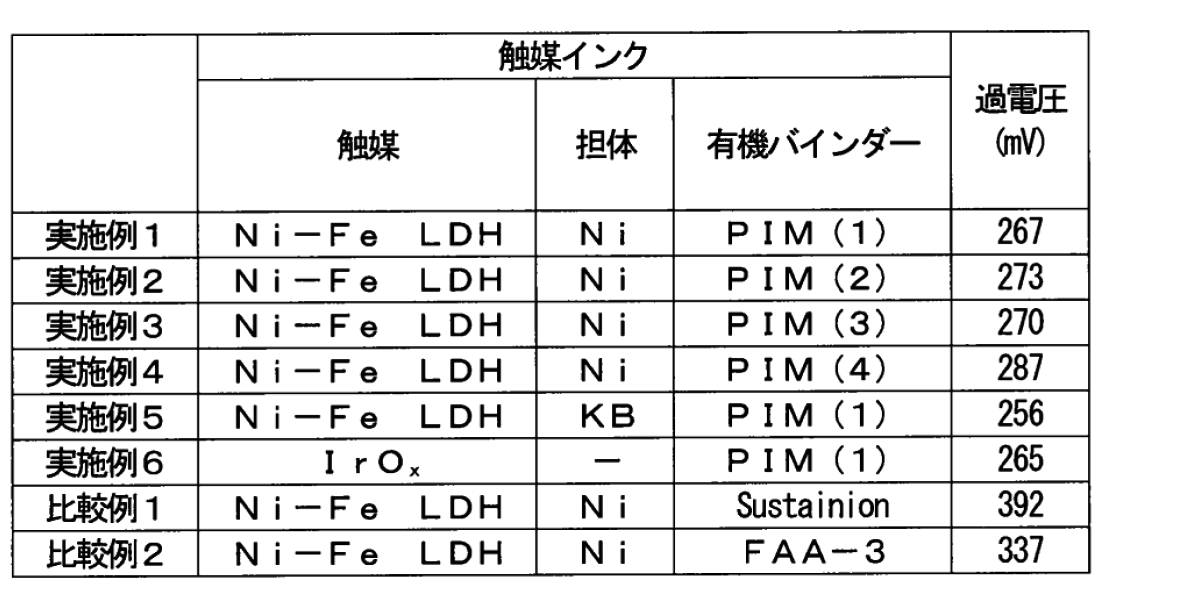
- Table 1 shows the measurement results of the overvoltage of the sample for evaluating the catalytic activity according to Examples 1 to 6 and Comparative Examples 1 and 2.
- Table 1 shows the overvoltage in the first cycle of the redox reaction.
- the catalyst inks according to Examples 1 to 6 had a low overvoltage in the redox cycle. As a result, in the catalyst inks according to Examples 1 to 6, the increase in overvoltage was suppressed. Since the intrinsic microporous polymer used as the organic binder in Examples 1 to 6 has porosity, the catalyst can be exposed from the intrinsic microporous polymer. As a result, it is considered that the increase in overvoltage was suppressed in the catalyst inks according to Examples 1 to 6. In addition, the catalytic ink according to Example 6 had a low overvoltage in the redox cycle. It was found that the catalytic ink has a low overvoltage even when IrO x , which is a conductive catalytic material, is used.
- the catalyst inks according to Comparative Examples 1 and 2 had a high overvoltage.
- no organic binder having porosity is used. Therefore, it is considered that the catalytic activity was lowered by coating the catalytic material with the organic binder.
- the electrode catalyst of the water electrolysis cell according to the present disclosure can be used in a water electrolysis device.
- Electrode catalyst Water electrolysis cell 3 Water electrolysis device 4 Alkaline water electrolysis cell 5 Alkaline water electrolysis device 10 Catalyst 11 Intrinsic microporous polymer (PIM) 20 LDH 21 Host layer 22 Guest layer 30, 32 Catalyst layer 31 Electrolyte film 33, 34 Gas diffusion layer 40 Voltage adapter 41 Diaphragm 50 First space 60 Second space 70 Electrolytic cell 100, 300 Anode 200, 400 Cathode
Landscapes
- Chemical & Material Sciences (AREA)
- Organic Chemistry (AREA)
- Engineering & Computer Science (AREA)
- Chemical Kinetics & Catalysis (AREA)
- Materials Engineering (AREA)
- Electrochemistry (AREA)
- Metallurgy (AREA)
- Inorganic Chemistry (AREA)
- Combustion & Propulsion (AREA)
- Electrolytic Production Of Non-Metals, Compounds, Apparatuses Therefor (AREA)
- Electrodes For Compound Or Non-Metal Manufacture (AREA)
Abstract
Description
触媒と、
中性の固有微多孔性ポリマーと、を備える、
水電解セルの電極触媒を提供する。
地球温暖化対策として、太陽光、及び風力などの再生可能エネルギーの利用が注目を浴びている。しかし、再生可能エネルギーによる発電では、余剰電力が無駄になるという問題が発生する。このため、再生可能エネルギーの利用効率は、必ずしも十分ではない。そこで、余剰電力から水素を製造して貯蔵する方法が検討されている。
本開示の第1態様に係る水電解セルの電極触媒は、
触媒と、
中性の固有微多孔性ポリマーと、を備える。
アノードと、
カソードと、
前記アノードと前記カソードとの間に配置された電解質膜と、
を備え、
前記アノード及び前記カソードからなる群から選ばれる少なくとも1つは、第1から第4態様のいずれか1つに係る電極触媒を含む。
第一空間と第二空間とを隔てる隔膜と、
前記第一空間に設けられたアノードと、
前記第二空間に設けられたカソードと、
を備え、
前記アノード及び前記カソードからなる群から選ばれる少なくとも1つは、第1から第4態様のいずれか1つに係る電極触媒を含む。
第5から第8態様のいずれか1つに係る水電解セルと、
前記アノード及び前記カソードに接続され、前記アノード及び前記カソードの間に電圧を印加する電圧印加器と、
を備える。
図1は、本実施形態に係る水電解セルの電極触媒を模式的に示す図である。本実施形態に係る電極触媒1は、触媒10と、中性の固有微多孔性ポリマー(PIM)11とを備えている。PIM11は、触媒10の表面の少なくとも一部に存在する。このような構成によれば、PIM11が触媒10の表面に存在していても触媒10の露出している表面の面積が小さくなりにくく、電極触媒1の触媒活性の低下が抑制されうる。このため、電極触媒1に電圧を印加した場合に、過電圧の増加が抑制されうる。つまり、電極触媒1は、低い過電圧を有しうる。
固有微多孔性ポリマー(PIM)11は、典型的には、特定の分子構造を有し、かつ固有の微多孔度を有する有機ポリマーである。


触媒10は、水電解セルのアノード又はカソードにおいて、水素及び酸素などのガスの生成反応に対して活性を有する材料である。触媒10の例は、金属及び金属酸化物である。金属の例は、Ptである。金属酸化物の例は、層状複水酸化物(LDH)及びIrOxである。
[M1 2+ 1-xM2 3+ x(OH)2][yAn-・mH2O] ・・・組成式(1)
電極触媒1は、担体をさらに含んでいてもよい。このような構成によれば、触媒10に対する担体によって触媒10が安定的に配置されるので、電極触媒1の触媒活性が高く保たれやすい。
図3は、本実施形態に係る水電解セルの一例を模式的に示す断面図である。
図4は、本実施形態に係る水電解装置の一例を模式的に示す断面図である。
図5は、本実施形態に係る水電解セルの別の一例を模式的に示す断面図である。
図6は、本実施形態に係る水電解装置の別の一例を模式的に示す断面図である。
(Ni担体に担持されたNi-Fe LDHの作製)
Ni-Fe LDH及びNi粒子を含む混合物を以下のようにして作製した。まず、水及びエタノール(富士フィルム和光純薬社製、試薬特級)の混合溶媒を作製した。水及びエタノールの体積比率は、2:3であった。この混合溶媒に、塩化ニッケル六水和物(富士フィルム和光純薬社製)及び塩化鉄六水和物(富士フィルム和光純薬社製)を、Niイオン及びFeイオンの合計濃度が1.0Mになるように、かつ、Niイオン及びFeイオンの総物質量に対するFeイオンの物質量の比率が0.33になるように溶解させた。なお、「M」は、mol/dm3を意味する。さらに、キレート剤としてアセチルアセトン(ACAC)を、Niイオン及びFeイオンの総物質量の3分の1の物質量になるように添加した。得られた溶液を、30分間撹拌した。この溶液に含まれているNiとFeが全て理想的に反応した場合に生成するNi-Fe LDHの質量と同一の質量のNi粒子(US Research Nanomaterials, Inc.製、粒径:40nm)を、この溶液に加えた。次に、Ni-Fe LDH及びNi粒子を含む溶液に、pH上昇剤としてプロピレンオキサイド(POX)を、溶液中の塩化物イオンの物質量の2倍量となるように添加した。得られた溶液を、1分間撹拌した。このとき、POXは、溶液中の水素イオンを徐々に捕捉するので、溶液のpHは徐々に上昇する。そのため、得られた溶液を3日間ほど静置した後、目的試料のNi-Fe LDH及びNi粒子の混合物を回収した。
実施例1に係るPIM(1)は、非特許文献2を参考にして作製した。4,4’-ジアミノ-3,3’-ジメチルビフェニル1mol等量をジメトキシメタン5mol等量に溶解させた。この溶液を0℃に冷却した。次に、この溶液に、トリフルオロ酢酸120mol等量を0.5時間かけて滴下した。この混合溶液を室温で5日間を撹拌した。次に、激しく撹拌した水酸化アンモニウム水溶液にこの混合溶液を加えて、2時間静置した。これにより得られた固体を濾過により集め、水、メタノール、アセトンの順で洗浄した。
Ni-Fe LDH及びNi粒子の混合物に対して、PIM(1)を、Ni-Fe LDH及びNi粒子の混合物とPIM(1)との質量比が20:1、かつ、総質量21mgとなるように混合した。得られた混合物に、クロロホルム(富士フィルム和光純薬社製、試薬特級)を1.05mL加え、触媒インク用液を調製した。触媒インク用液を超音波ホモジナイザーによって30分間微細処理することによって、実施例1に係る触媒インクを調製した。10μLの実施例1に係る触媒インクを回転ディスク電極に滴下して、室温にて乾燥させることによって、実施例1に係る触媒活性の評価用試料を得た。
有機バインダーとして、PIM(1)に代えて、PIM(2)を用いたことを除き、実施例1と同様にして、実施例2に係る触媒活性の評価用試料を得た。PIM(2)は、以下の構造式により表される有機高分子である。PIM(2)は、トレーガー塩基骨格を有する有機高分子である。
有機バインダーとして、PIM(1)に代えて、PIM(3)を用いたことを除き、実施例1と同様にして、実施例3に係る触媒活性の評価用試料を得た。PIM(3)は、以下の構造式により表される有機高分子である。PIM(3)は、トレーガー塩基骨格を有する有機高分子である。
有機バインダーとして、PIM(1)に代えて、PIM(4)を用いたことを除き、実施例1と同様にして、実施例4に係る触媒活性の評価用試料を得た。PIM(4)は、以下の構造式により表される有機高分子である。PIM(4)は、トレーガー塩基骨格を有する有機高分子である。

(ケッチェンブラック担体に担持されたNi-Fe LDHの作製)
Ni-Fe LDHを以下のようにして作製した。まず、水及びエタノール(富士フィルム和光純薬社製、試薬特級)の混合溶媒を作製した。水及びエタノールの体積比率は、2:3であった。この混合溶媒に、塩化ニッケル六水和物(富士フィルム和光純薬社製)及び塩化鉄六水和物(富士フィルム和光純薬社製)を、Niイオン及びFeイオンの合計濃度が1.0Mになるように、かつ、Niイオン及びFeイオンの総物質量に対するFeイオンの物質量の比率が0.33になるように溶解させた。なお、「M」は、mol/dm3を意味する。さらに、キレート剤としてアセチルアセトン(ACAC)を、Niイオン及びFeイオンの総物質量の3分の1の物質量になるように添加した。得られた溶液を、30分間撹拌した。その後、pH上昇剤としてプロピレンオキサイド(POX)を、溶液中の塩化物イオンの物質量の2倍量となるように添加し、1分間撹拌した。このとき、POXは、溶液中の水素イオンを徐々に捕捉するので、溶液のpHは徐々に上昇する。そこで、3日間ほど静置した後、目的試料のLDHを回収した。なお、以上のLDHの調製方法は、例示であって本例に限定されない。ここで、リガク社製のSmartLabを用いたX線小角散乱法(SAXS)に従って、溶液に分散しているNi-Fe LDHの粒度分布を得た。得られた粒径と分布との関係を2次元分布図で表し、2次元分布図の面積を総粒子数で割って、LDHの平均粒径を決定した。Ni-Fe LDHの平均粒径は10nmであった。
Ni-Fe LDH及びNi粒子の混合物に代えて、田中貴金属社製のIrOx SA100を用いたことと、IrOx及びPIM(1)の質量比が5:1、かつ、総質量6mgとなるように混合したこととを除き、実施例1と同様にして、実施例6に係る触媒活性の評価用試料を得た。
有機バインダーとして、PIM(1)に代えて、Dioxide Materials社製のSustainionを用いたことを除き、実施例1と同様にして、比較例1に係る触媒活性の評価用試料を得た。
有機バインダーとして、PIM(1)に代えて、Fumatech社製のFAA-3を用いたことと、クロロホルムを1.03mL使用したこととを除き、実施例1と同様にして、比較例2に係る触媒活性の評価用試料を得た。
各実施例及び各比較例に係る触媒活性の評価用試料の過電圧を測定した。測定には、Princeton Applied Research社製のポテンシオスタットVersaSTAT4及びPine Research社製の回転電極AFE3T050GCを用いた。回転ディスク電極(RDE)法によって、以下の測定条件で、水電解セルのアノード反応由来の電流を測定した。アノード反応は、酸素発生反応である。結果を表1に示す。
[測定条件]
・溶液:1M KOH溶液
・電位:1.0Vから1.65V(vs.可逆水素電極(RHE))
・電位掃引速度:10mV/sec
・電極回転速度:1500revolutions per minute(rpm)
2 水電解セル
3 水電解装置
4 アルカリ水電解セル
5 アルカリ水電解装置
10 触媒
11 固有微多孔性ポリマー(PIM)
20 LDH
21 ホスト層
22 ゲスト層
30,32 触媒層
31 電解質膜
33,34 ガス拡散層
40 電圧印加器
41 隔膜
50 第一空間
60 第二空間
70 電解槽
100,300 アノード
200,400 カソード
Claims (9)
- 触媒と、
中性の固有微多孔性ポリマーと、を備える、
水電解セルの電極触媒。 - 前記固有微多孔性ポリマーは、トレーガー塩基骨格を有する、
請求項1に記載の水電解セルの電極触媒。 - 前記固有微多孔性ポリマーは、スピロビインダン骨格を有する、
請求項1に記載の水電解セルの電極触媒。 - 前記固有微多孔性ポリマーは、ポリイミド骨格を有する、
請求項1に記載の水電解セルの電極触媒。 - アノードと、
カソードと、
前記アノードと前記カソードとの間に配置された電解質膜と、
を備え、
前記アノード及び前記カソードからなる群から選ばれる少なくとも1つは、請求項1から4のいずれか1項に記載の電極触媒を含む、
水電解セル。 - 前記電解質膜は、プロトン交換膜を含む、
請求項5に記載の水電解セル。 - 前記電解質膜は、アニオン交換膜を含む、
請求項5に記載の水電解セル。 - 第一空間と第二空間とを隔てる隔膜と、
前記第一空間に設けられたアノードと、
前記第二空間に設けられたカソードと、
を備え、
前記アノード及び前記カソードからなる群から選ばれる少なくとも1つは、請求項1から4のいずれか1項に記載の電極触媒を含む、
水電解セル。 - 請求項5から8のいずれか1項に記載の水電解セルと、
前記アノード及び前記カソードに接続され、前記アノード及び前記カソードの間に電圧を印加する電圧印加器と、
を備える、
水電解装置。
Priority Applications (4)
| Application Number | Priority Date | Filing Date | Title |
|---|---|---|---|
| EP21841344.1A EP4183900B1 (en) | 2020-07-17 | 2021-06-16 | Electrode catalyst for water electrolysis cells, water electrolysis cell, and water electrolysis device |
| JP2021549705A JP6979624B1 (ja) | 2020-07-17 | 2021-06-16 | 水電解セルの電極触媒、水電解セル、及び水電解装置 |
| CN202180061479.8A CN116157202B (zh) | 2020-07-17 | 2021-06-16 | 水电解单元的电极催化剂、水电解单元及水电解装置 |
| US18/150,685 US20230160082A1 (en) | 2020-07-17 | 2023-01-05 | Electrode catalyst for water electrolysis cell, water electrolysis cells, and water electrolysis devices |
Applications Claiming Priority (2)
| Application Number | Priority Date | Filing Date | Title |
|---|---|---|---|
| JP2020122911 | 2020-07-17 | ||
| JP2020-122911 | 2020-07-17 |
Related Child Applications (1)
| Application Number | Title | Priority Date | Filing Date |
|---|---|---|---|
| US18/150,685 Continuation US20230160082A1 (en) | 2020-07-17 | 2023-01-05 | Electrode catalyst for water electrolysis cell, water electrolysis cells, and water electrolysis devices |
Publications (1)
| Publication Number | Publication Date |
|---|---|
| WO2022014243A1 true WO2022014243A1 (ja) | 2022-01-20 |
Family
ID=79555420
Family Applications (1)
| Application Number | Title | Priority Date | Filing Date |
|---|---|---|---|
| PCT/JP2021/022953 Ceased WO2022014243A1 (ja) | 2020-07-17 | 2021-06-16 | 水電解セルの電極触媒、水電解セル、及び水電解装置 |
Country Status (1)
| Country | Link |
|---|---|
| WO (1) | WO2022014243A1 (ja) |
Citations (7)
| Publication number | Priority date | Publication date | Assignee | Title |
|---|---|---|---|---|
| WO2005012397A2 (en) | 2003-07-26 | 2005-02-10 | The University Of Manchester | Microporous polymer material |
| JP2012519061A (ja) * | 2009-02-27 | 2012-08-23 | エボニック オクセノ ゲゼルシャフト ミット ベシュレンクテル ハフツング | プロセス流から均一系触媒を富化する方法 |
| JP2014512251A (ja) * | 2011-02-08 | 2014-05-22 | アンスティチュ ナショナル ド ラ ルシェルシュ シアンティフィーク | 熱分解性多孔質担体を使用して製造される触媒 |
| US20140255636A1 (en) | 2013-03-06 | 2014-09-11 | Saudi Basic Industries Corporation | Polymeric Membranes |
| WO2017091357A1 (en) | 2015-11-24 | 2017-06-01 | Dow Global Technologies Llc | Troger's base polymers having intrinsic microporosity |
| US20200006796A1 (en) * | 2018-06-29 | 2020-01-02 | c/o FORM ENERGY INC. | Aqueous polysulfide-based electrochemical cell |
| JP2020502738A (ja) * | 2016-12-07 | 2020-01-23 | セピオン テクノロジーズ,インコーポレイティド | 微細構造化イオン伝導性複合体及びその使用 |
-
2021
- 2021-06-16 WO PCT/JP2021/022953 patent/WO2022014243A1/ja not_active Ceased
Patent Citations (7)
| Publication number | Priority date | Publication date | Assignee | Title |
|---|---|---|---|---|
| WO2005012397A2 (en) | 2003-07-26 | 2005-02-10 | The University Of Manchester | Microporous polymer material |
| JP2012519061A (ja) * | 2009-02-27 | 2012-08-23 | エボニック オクセノ ゲゼルシャフト ミット ベシュレンクテル ハフツング | プロセス流から均一系触媒を富化する方法 |
| JP2014512251A (ja) * | 2011-02-08 | 2014-05-22 | アンスティチュ ナショナル ド ラ ルシェルシュ シアンティフィーク | 熱分解性多孔質担体を使用して製造される触媒 |
| US20140255636A1 (en) | 2013-03-06 | 2014-09-11 | Saudi Basic Industries Corporation | Polymeric Membranes |
| WO2017091357A1 (en) | 2015-11-24 | 2017-06-01 | Dow Global Technologies Llc | Troger's base polymers having intrinsic microporosity |
| JP2020502738A (ja) * | 2016-12-07 | 2020-01-23 | セピオン テクノロジーズ,インコーポレイティド | 微細構造化イオン伝導性複合体及びその使用 |
| US20200006796A1 (en) * | 2018-06-29 | 2020-01-02 | c/o FORM ENERGY INC. | Aqueous polysulfide-based electrochemical cell |
Non-Patent Citations (2)
| Title |
|---|
| CANGHAI MA ET AL.: "Polymers of Intrinsic Microporosity (PIMs) Gas Separation Membranes: A mini Review", PROCEEDINGS OF THE NATURE RESEARCH SOCIETY, vol. 2, no. 02002, 2018, pages 1 - 19 |
| MARIOLINO CARTA ET AL.: "The synthesis of microporous polymers using Troger's base formation", POLYMER CHEMISTRY, vol. 5, 2014, pages 5267 - 5272, XP055770813, DOI: 10.1039/C4PY00609G |
Similar Documents
| Publication | Publication Date | Title |
|---|---|---|
| Wang et al. | Iridium‐based catalysts for solid polymer electrolyte electrocatalytic water splitting | |
| Wang et al. | Polymer-assisted approach to LaCo1-xNixO3 network nanostructures as bifunctional oxygen electrocatalysts | |
| Zheng et al. | Bimetallic metal–organic-framework/reduced graphene oxide composites as bifunctional electrocatalysts for rechargeable Zn–air batteries | |
| Yi et al. | Co-CoO-Co3O4/N-doped carbon derived from metal-organic framework: The addition of carbon black for boosting oxygen electrocatalysis and Zn-Air battery | |
| Zhu et al. | Monolithic-structured ternary hydroxides as freestanding bifunctional electrocatalysts for overall water splitting | |
| JP7029687B1 (ja) | アノード触媒、水電解セル用触媒、水電解セル、水電解装置、およびアノード触媒の製造方法 | |
| Fu et al. | Ni–Fe nanocubes embedded with Pt nanoparticles for hydrogen and oxygen evolution reactions | |
| Zhao et al. | Ni-doped CoFe2O4 hollow nanospheres as efficient bi-functional catalysts | |
| JP7018569B1 (ja) | 水電解セルの電極触媒、水電解セル、及び水電解装置 | |
| Choi et al. | Boosting eco-friendly hydrogen generation by urea-assisted water electrolysis using spinel M 2 GeO 4 (M= Fe, Co) as an active electrocatalyst | |
| Li et al. | Novel configuration of bifunctional air electrodes for rechargeable zinc–air batteries | |
| US20230160082A1 (en) | Electrode catalyst for water electrolysis cell, water electrolysis cells, and water electrolysis devices | |
| Chanda et al. | Electrochemical synthesis of Li-doped NiFeCo oxides for efficient catalysis of the oxygen evolution reaction in an alkaline environment | |
| Ma et al. | Nanosheet-structured NiCoO2/carbon nanotubes hybrid composite as a novel bifunctional oxygen electrocatalyst | |
| Varsha et al. | A ligand-specific bimetallic electrocatalyst for efficient oxygen evolution reaction at higher current density | |
| Kim et al. | Synthesis and electrochemical properties of nano-composite IrO2/TiO2 anode catalyst for SPE electrolysis cell | |
| Imani et al. | In situ synthesis of a novel organic-inorganic composite as a non-noble metal electrocatalyst for the oxygen evolution reaction | |
| Zhang et al. | Efficient alcohol electro-oxidation based on a 3D Ni (II)-MOF with centrosymmetric Ni6 cluster | |
| Xiao et al. | Enhanced performance of direct peroxide/peroxide fuel cell by using ultrafine Nickel Ferric Ferrocyanide nanoparticles as the cathode catalyst | |
| Shuai et al. | The influence of MOF modification on oxygen evolution and reduction reaction of Fe-doped GdBaCo2O5+ δ perovskite | |
| Xu et al. | Cu 2 O–reduced graphene oxide composite as a high-performance electrocatalyst for oxygen evolution reaction in alkaline media | |
| WO2022014243A1 (ja) | 水電解セルの電極触媒、水電解セル、及び水電解装置 | |
| Pai et al. | Platinum/vivianite bifunction catalysts for DMFC | |
| JP7033741B1 (ja) | 水電解セルの電極触媒、水電解セル、及び水電解装置 | |
| Skakri et al. | Facile synthesis of a Ni–Cu composite reinforced with a para-phenylenediamine layer for enhanced hydrogen evolution reaction |
Legal Events
| Date | Code | Title | Description |
|---|---|---|---|
| ENP | Entry into the national phase |
Ref document number: 2021549705 Country of ref document: JP Kind code of ref document: A |
|
| 121 | Ep: the epo has been informed by wipo that ep was designated in this application |
Ref document number: 21841344 Country of ref document: EP Kind code of ref document: A1 |
|
| NENP | Non-entry into the national phase |
Ref country code: DE |
|
| ENP | Entry into the national phase |
Ref document number: 2021841344 Country of ref document: EP Effective date: 20230217 |
|
| WWG | Wipo information: grant in national office |
Ref document number: 2021841344 Country of ref document: EP |