WO2022014349A1 - 回転コネクタ装置 - Google Patents
回転コネクタ装置 Download PDFInfo
- Publication number
- WO2022014349A1 WO2022014349A1 PCT/JP2021/025012 JP2021025012W WO2022014349A1 WO 2022014349 A1 WO2022014349 A1 WO 2022014349A1 JP 2021025012 W JP2021025012 W JP 2021025012W WO 2022014349 A1 WO2022014349 A1 WO 2022014349A1
- Authority
- WO
- WIPO (PCT)
- Prior art keywords
- case
- movable member
- rotation
- cable
- radial position
- Prior art date
- Legal status (The legal status is an assumption and is not a legal conclusion. Google has not performed a legal analysis and makes no representation as to the accuracy of the status listed.)
- Ceased
Links
Images


Classifications
-
- H—ELECTRICITY
- H01—ELECTRIC ELEMENTS
- H01R—ELECTRICALLY-CONDUCTIVE CONNECTIONS; STRUCTURAL ASSOCIATIONS OF A PLURALITY OF MUTUALLY-INSULATED ELECTRICAL CONNECTING ELEMENTS; COUPLING DEVICES; CURRENT COLLECTORS
- H01R35/00—Flexible or turnable line connectors, i.e. the rotation angle being limited
- H01R35/02—Flexible line connectors without frictional contact members
- H01R35/025—Flexible line connectors without frictional contact members having a flexible conductor wound around a rotation axis
-
- B—PERFORMING OPERATIONS; TRANSPORTING
- B60—VEHICLES IN GENERAL
- B60R—VEHICLES, VEHICLE FITTINGS, OR VEHICLE PARTS, NOT OTHERWISE PROVIDED FOR
- B60R16/00—Electric or fluid circuits specially adapted for vehicles and not otherwise provided for; Arrangement of elements of electric or fluid circuits specially adapted for vehicles and not otherwise provided for
- B60R16/02—Electric or fluid circuits specially adapted for vehicles and not otherwise provided for; Arrangement of elements of electric or fluid circuits specially adapted for vehicles and not otherwise provided for electric constitutive elements
- B60R16/023—Electric or fluid circuits specially adapted for vehicles and not otherwise provided for; Arrangement of elements of electric or fluid circuits specially adapted for vehicles and not otherwise provided for electric constitutive elements for transmission of signals between vehicle parts or subsystems
- B60R16/027—Electric or fluid circuits specially adapted for vehicles and not otherwise provided for; Arrangement of elements of electric or fluid circuits specially adapted for vehicles and not otherwise provided for electric constitutive elements for transmission of signals between vehicle parts or subsystems between relatively movable parts of the vehicle, e.g. between steering wheel and column
-
- H—ELECTRICITY
- H01—ELECTRIC ELEMENTS
- H01R—ELECTRICALLY-CONDUCTIVE CONNECTIONS; STRUCTURAL ASSOCIATIONS OF A PLURALITY OF MUTUALLY-INSULATED ELECTRICAL CONNECTING ELEMENTS; COUPLING DEVICES; CURRENT COLLECTORS
- H01R35/00—Flexible or turnable line connectors, i.e. the rotation angle being limited
- H01R35/04—Turnable line connectors with limited rotation angle with frictional contact members
-
- H—ELECTRICITY
- H02—GENERATION; CONVERSION OR DISTRIBUTION OF ELECTRIC POWER
- H02G—INSTALLATION OF ELECTRIC CABLES OR LINES, OR OF COMBINED OPTICAL AND ELECTRIC CABLES OR LINES
- H02G11/00—Arrangements of electric cables or lines between relatively-movable parts
- H02G11/02—Arrangements of electric cables or lines between relatively-movable parts using take-up reel or drum
Definitions
- the technology disclosed in this application relates to a rotary connector device.
- Patent Document 1 describes a rotary connector used for a vehicle.
- the technical problem disclosed in the present application is to suppress the malfunction of the stopper structure due to individual differences in products and dimensional errors.
- the rotary connector device includes a first case, a second case, an electric cable, and a stopper structure.
- the first case and the second case are provided so as to be able to rotate relative to each other around the rotation axis, and form a cable accommodating space provided so as to surround the rotation axis.
- the electric cable is provided in the cable accommodation space so as to be wound in the circumferential direction defined around the axis of rotation.
- the stopper structure is configured to limit the relative rotation of the first case and the second case to a predetermined rotation angle.
- the stopper structure includes a movable member, a rotation limiting portion, and a guide portion.
- the movable member can move in the radial direction orthogonal to the rotation axis between the first radial position and the second radial position with respect to the second case.
- the rotation limiting portion is provided in the first case, and can come into contact with the movable member in the circumferential direction so as to limit the relative rotation of the first case and the second case while the movable member is in the second radial position.
- the guide portion is provided in the first case and can come into contact with the movable member so as to guide the movable member toward the first radial position.
- the movable member comes into contact with the guide portion while the movable member is in a position other than the second radial position, the movable member is moved to the first radial position by the guide portion. You will be guided to. Therefore, due to the minute movement of the movable member with respect to the second case due to individual differences in products, dimensional errors, etc., the movable member comes into contact with the rotation limiting portion in an unintended state, and the relative rotation of the first case and the second case occurs. It can be suppressed from being restricted. That is, it suppresses malfunction of the stopper structure due to individual differences in products and dimensional errors.
- the rotation limiting portion is arranged on the radial outside of the guide portion.
- a larger rotational force can be received by the rotation limiting portion, and the strength of the stopper structure can be increased.
- the rotation limiting portion includes a stopper surface capable of contacting the movable member in the circumferential direction.
- the guide portion projects in the circumferential direction from the stopper surface.
- the movable member can be reliably guided toward the first radial position by the guide portion.
- the guide portion includes a guide surface that is inclined with respect to the circumferential direction when viewed along the rotation axis. ..
- the movable member can be more reliably guided toward the first radial position by the guide surface.
- the guide portion is in the state where the movable member is in the second radial position and the movable member is in the first radial position. It is configured to restrict movement towards.
- the contact state between the movable member and the rotation limiting portion can be stabilized in a state where the movable member is in contact with the rotation limiting portion at the second radial position.
- the movable member in the rotary connector device according to any one of the first to fifth features, is inserted at least partially in a state where the movable member is in contact with the rotation limiting portion. Includes a stopper groove.
- the contact state between the movable member and the rotation limiting portion can be more stabilized in a state where the movable member is in contact with the rotation limiting portion at the second radial position.
- the movable member has a stopper body rotatably connected to the second case around the stopper rotation axis and a stopper. Includes an axially projecting portion defined along the axis of rotation from the body and a rotation limiting portion and a circumferentially contactable projecting portion.
- the shape and position of the protruding portion are less likely to be affected by the shape and position of the stopper body, and the degree of freedom in designing the movable member is increased.
- the stopper main body is a cable contact surface capable of contacting the electric cable so as to receive a radial force from the electric cable according to the state of the electric cable. including.
- the movable member can be moved in the radial direction by using an electric cable, and the structure can be simplified.
- the protrusion is provided radially inside the cable contact surface when viewed along the rotation axis.
- the protrusion can be arranged outside the cable accommodation space.
- the protruding portion is radially separated from the rotation limiting portion in the state where the movable member is in the first radial position. It is placed in the same position.
- the movable member moves to the first radial position and the second radial position according to the state of the electric cable. It is possible.
- the movable member can be moved toward the first radial position and the second radial position by using an electric cable, and the structure can be simplified.
- the first case includes an inner peripheral surface that partially forms a cable accommodating space.
- the second case includes an outer peripheral surface provided radially inside the inner peripheral surface to partially form a cable accommodation space.
- the electric cable has a first winding portion wound along the inner peripheral surface of the first case, a second winding portion wound along the outer peripheral surface of the second case, and a first winding portion and a second winding portion. It includes an intermediate portion provided between them and connecting the first winding portion to the second winding portion.
- the electric cable is provided in the cable accommodating space so that the length of the second winding portion of the electric cable wound around the outer peripheral surface decreases when the second case rotates in the first rotation direction with respect to the first case. ..
- the electric cable when the second case rotates in the second rotation direction opposite to the first rotation direction with respect to the first case, the length of the second winding portion of the electric cable wound around the outer peripheral surface increases. , Installed in the cable accommodation space.
- the urging force of the electric cable for urging the movable member toward the first radial position becomes smaller.
- the urging force of the electric cable to urge the movable member toward the first radial position becomes large.
- the movable member can be moved toward the first radial position and the second radial position by utilizing the relative rotation of the first case and the second case, and the structure is simplified. It becomes possible to change.
- the first case is a stator configured to be fixed to the vehicle body.
- the second case is a rotator that can rotate about the axis of rotation with respect to the stator.
- the movable member is rotatably connected to the rotator around the stopper rotation axis.
- the rotation limiting portion is provided on the stator.
- a larger force can be received by the rotation limiting portion provided on the stator, and the strength of the stopper structure can be increased.
- the technology disclosed in the present application can provide a rotary connector device capable of limiting the rotation angle of the rotator with respect to the stator to a predetermined rotation angle by a simple structure.
- FIG. 1 is a perspective view of a rotary connector device according to an embodiment.
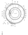
- FIG. 2 is a cross-sectional view of the rotary connector device in lines II-II of FIG.
- FIG. 3 is a perspective view of the stopper structure of the rotary connector device shown in FIG.
- FIG. 4 is an exploded perspective view of the rotary connector device shown in FIG.
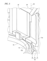
- FIG. 5 is a cross-sectional view of the stopper structure shown in FIG.
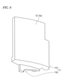
- FIG. 6 is a perspective view of a movable member having a stopper structure shown in FIG.
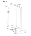
- FIG. 7 is a perspective view of a movable member having a stopper structure shown in FIG.
- FIG. 8 is a plan view of the stopper structure shown in FIG.
- FIG. 9 is a plan view of the stopper structure shown in FIG.
- FIG. 10 is an operation explanatory view of the stopper structure shown in FIG.
- FIG. 11 is an operation explanatory view of the stopper structure shown in FIG.
- the rotary connector device 1 includes a first case 10 and a second case 20.
- the first case 10 and the second case 20 are provided so as to be rotatable relative to each other around the rotation axis A1.
- the first case 10 is configured to be fixed to the vehicle body.
- the second case 20 is configured to rotate with the steering wheel. That is, the first case 10 is a stator configured to be fixed to the vehicle body.
- the second case 20 is a rotator that can rotate around the rotation axis A1 with respect to the stator. Therefore, the first case 10 may be referred to as a stator 10.
- the second case 20 may be referred to as a rotator 20.
- the first case 10 may be a rotator and the second case 20 may be a stator. That is, in the present application, the configuration provided in the stator 10 may be provided in the rotator 20, and the configuration provided in the rotator 20 may be provided in the stator 10.
- the rotary connector device 1 includes a first electric connector 30 and a second electric connector 40.
- the first electric connector 30 is attached to the first case 10.
- the first electric connector 30 projects from the first case 10 in the axial direction D1 defined along the rotation axis A1.
- the second electric connector 40 is attached to the second case 20.
- the first electric connector 30 is configured to be electrically connected to, for example, an electric device (for example, a control device and a battery) provided in the vehicle body.
- the second electric connector 40 is configured to be electrically connected to, for example, an electric circuit such as a switch of a steering wheel or an airbag device.
- the first case 10 and the second case 20 form a cable accommodating space 50 provided so as to surround the rotation axis A1.
- the cable accommodating space 50 is annular and extends in the circumferential direction D3 with respect to the rotation axis A1.
- the rotary connector device 1 includes an electric cable 60.
- the electric cable 60 is provided in the cable accommodating space 50 so as to be wound in the circumferential direction D3 defined around the rotation axis A1.
- the electric cable 60 is electrically connected to the first electric connector 30 and the second electric connector 40 (FIG. 1).
- the electric cable 60 is flexible and has a flat shape.
- the electric cable 60 may also be referred to as a flexible flat cable.
- the electric cable 60 includes a plurality of flat cables 61.
- the first case 10 includes an inner peripheral surface 10B that partially forms the cable accommodating space 50.
- the second case 20 includes an outer peripheral surface 20B provided inside the inner peripheral surface 10B in the radial direction and partially forming the cable accommodating space 50.
- the electric cable 60 includes a first winding portion 60A, a second winding portion 60B, and an intermediate portion 60C.
- the first winding portion 60A is wound along the inner peripheral surface 10B of the first case 10.
- the second winding portion 60B is wound along the outer peripheral surface 20B of the second case 20.
- the intermediate portion 60C is provided between the first winding portion 60A and the second winding portion 60B, and connects the first winding portion 60A to the second winding portion 60B.
- the first winding portion 60A is electrically connected to the first electric connector 30.
- the second winding portion 60B is electrically connected to the second electric connector 40 (FIG. 1).
- the intermediate portion 60C is bent between the first winding portion 60A and the second winding portion 60B.
- the intermediate portion 60C has, for example, a curved shape protruding in the first rotation direction D21.
- Each of the plurality of flat cables 61 includes a first winding portion 60A, a second winding portion 60B, and an intermediate portion 60C.
- the electric cable 60 is provided so that when the second case 20 rotates in the first rotation direction D21 with respect to the first case 10, the length of the second winding portion 60B of the electric cable 60 wound around the outer peripheral surface 20B decreases. It is provided in the cable accommodation space 50.
- the electric cable 60 when the second case 20 rotates in the second rotation direction D22 opposite to the first rotation direction D21 with respect to the first case 10, the second winding portion 60B of the electric cable 60 is wound around the outer peripheral surface 20B. It is provided in the cable accommodating space 50 so that the length of the cable is increased.
- the electric cable 60 has a length in which the first winding portion 60A of the electric cable 60 is wound around the inner peripheral surface 10B when the second case 20 rotates in the first rotation direction D21 with respect to the first case 10. It is provided in the cable accommodating space 50 so as to increase. In the electric cable 60, when the second case 20 rotates in the second rotation direction D22 with respect to the first case 10, the length of the first winding portion 60A of the electric cable 60 wound around the inner peripheral surface 10B decreases. , Provided in the cable accommodating space 50.
- the electric cable 60 may loosen and the state of the intermediate portion 60C of the electric cable 60 may be disrupted.
- the rotary connector device 1 includes a stopper structure 70 configured to limit the relative rotation of the first case 10 and the second case 20 to a predetermined rotation angle.
- the stopper structure 70 includes a movable member 71, a rotation limiting portion 72, and a guide portion 73.
- the movable member 71 is rotatably connected to the rotator 20 around the stopper rotation axis A2.
- the rotation limiting unit 72 is provided in the first case 10.
- the guide portion 73 is provided in the first case 10.
- the rotation limiting portion 72 is provided on the stator 10.
- the guide portion 73 is provided on the stator 10.
- the movable member 71 may be rotatably connected to the stator 10.
- the rotation limiting unit 72 may be provided on the rotator 20.
- the guide portion 73 may be provided in the rotator 20.
- the second case 20 includes the second case main body 21 and the connector support portion 22.
- the connector support portion 22 is a separate member from the second case main body 21, and is attached to the second case main body 21.
- the movable member 71 is rotatably connected to the connector support portion 22 around the stopper rotation axis A2.
- the stopper body 71A is rotatably connected to the connector support portion 22 around the stopper rotation axis A2.
- the stopper structure 70 includes a pivot pin 74.
- the pivot pin 74 connects the movable member 71 to the second case 20 so as to be rotatable around the stopper rotation axis A2.
- the connector support 22 may be integrally provided with the second case body 21 as a single (one-piece) member.
- the pivot pin 74 may be provided integrally with one of the second case 20 and the movable member 71 as a single member.
- the movable member 71 includes a stopper main body 71A and a protruding portion 71B.
- the stopper body 71A is rotatably connected to the second case 20 around the stopper rotation axis A2.
- the protruding portion 71B protrudes from the stopper main body 71A in the axial direction D1 defined along the rotation axis A1.
- the stopper rotation axis A2 is arranged parallel to the rotation axis A1. However, the stopper rotation axis A2 may be arranged non-parallel to the rotation axis A1.
- the movable member 71 is movable in the radial direction D4 orthogonal to the rotation axis A1 between the first radial position P11 and the second radial position P12 with respect to the second case 20.
- the movable member 71 can rotate about the stopper rotation axis A2 between the first radial position P11 and the second radial position P12 with respect to the second case 20.
- the second radial position P12 is arranged radially outside the first radial position P11. However, the second radial position P12 may be arranged radially inside the first radial position P11.
- the stopper body 71A includes the cable contact surface 75.
- the cable contact surface 75 can come into contact with the electric cable 60 so as to receive a radial force from the electric cable 60 depending on the state of the electric cable 60 (see, for example, FIG. 2).
- the cable contact surface 75 includes a first cable contact surface 75A and a second cable contact surface 75B.
- the second cable contact surface 75B is arranged on the back side of the first cable contact surface 75A.
- the second cable contact surface 75B is arranged radially inside the first cable contact surface 75A.
- the first cable contact surface 75A is configured to face radially outward with the movable member 71 at the first radial position P11.
- the second cable contact surface 75B is configured to face radially inward with the movable member 71 at the first radial position P11.
- the first cable contact surface 75A can come into contact with the electric cable 60 so as to receive a urging force radially inward from the electric cable 60.
- the second cable contact surface 75B can come into contact with the electric cable 60 so as to receive an urging force radially outward from the electric cable 60.
- the protrusion 71B is provided radially inside the cable contact surface 75 when viewed along the rotation axis A1.
- the protrusion 71B is provided radially inside the first cable contact surface 75A when viewed along the rotation axis A1.
- the protrusion 71B is provided radially inside the second cable contact surface 75B when viewed along the rotation axis A1.
- the protrusion 71B may be provided at the same radial position as the cable contact surface 75 when viewed along the rotation axis A1, or may be provided radially outside the cable contact surface 75.
- the rotation limiting portion 72 is circumferential with the movable member 71 so as to limit the relative rotation of the first case 10 and the second case 20 while the movable member 71 is in the second radial position P12. It is possible to contact D3.
- the protruding portion 71B can come into contact with the rotation limiting portion 72 in the circumferential direction D3.
- the rotation limiting portion 72 includes a stopper surface 72A that can come into contact with the movable member 71 in the circumferential direction D3.
- the stopper surface 72A is arranged so as to face the circumferential direction D3.
- the stopper surface 72A is arranged so as to face the second rotation direction D22.
- the protruding portion 71B can come into contact with the rotation limiting portion 72 and the circumferential direction D3.
- the radial position of the protruding portion 71B is substantially the same as the radial position of the rotation limiting portion 72.
- the protruding portion 71B is arranged at a position radially separated from the rotation limiting portion 72 with the movable member 71 at the first radial position P11. With the movable member 71 at the first radial position P11, the radial position of the protruding portion 71B is different from the radial position of the rotation limiting portion 72. In the present embodiment, with the movable member 71 at the first radial position P11, the protruding portion 71B is arranged radially inside the rotation limiting portion 72. However, with the movable member 71 at the first radial position P11, the protruding portion 71B may be arranged radially outside the rotation limiting portion 72.
- the first case 10 includes an annular groove 15.
- the protrusion 71B is arranged in the annular groove 15 with the movable member 71 at the first radial position P11. Therefore, with the movable member 71 in the first radial position P11, the second case 20 can rotate in the first rotation direction D21 and the second rotation direction D22 with respect to the first case 10.
- the protruding portion 71B of the movable member 71 becomes the stopper surface of the rotation limiting portion 72.
- the rotation of the second case 20 with respect to the first case 10 in the first rotation direction D21 is stopped.
- the stopper surface 72A faces the second rotation direction D22, the second case 20 rotates in the second rotation direction D22 with respect to the first case 10 in a state where the movable member 71 is urged outward in the radial direction.
- the rotation of the second case 20 with respect to the first case 10 in the second rotation direction D22 is not limited.
- the guide portion 73 is in contact with the movable member 71 so as to guide the movable member 71 toward the first radial position P11.
- the guide portion 73 sets the movable member 71 at the first radial position P11. It can come into contact with the movable member 71 so as to guide the direction. With the movable member 71 between the first radial position P11 and the intermediate position P13, the guide portion 73 can contact the movable member 71 so as to guide the movable member 71 toward the first radial position P11. Is.
- the rotation limiting portion 72 is arranged outside the guide portion 73 in the radial direction.
- the guide portion 73 projects from the stopper surface 72A in the circumferential direction D3.
- the guide portion 73 includes a guide surface 73A that is inclined with respect to the circumferential direction D3 when viewed along the rotation axis A1.
- the guide surface 73A is arranged so as to face inward in the radial direction.
- the guide portion 73 does not have to protrude from the stopper surface 72A in the circumferential direction D3.
- the guide surface 73A may be configured to extend radially inward from the stopper surface 72A.
- the guide surface 73A is a flat surface, but may be a curved surface.
- the guide portion 73 is configured to restrict the movable member 71 from moving toward the first radial position P11 while the movable member 71 is in the second radial position P12.
- the stopper structure 70 includes a stopper groove 72B defined by a rotation limiting portion 72 and a guide portion 73.
- the movable member 71 is inserted into the stopper groove 72B at least partially in a state where the movable member 71 is in contact with the rotation limiting portion 72.
- the protrusion 71B is partially inserted into the stopper groove 72B in a state where the protrusion 71B is in contact with the rotation limiting portion 72. If the guide portion 73 does not project from the stopper surface 72A in the circumferential direction D3, the stopper groove 72B may be omitted.
- the guide unit 73 includes the restriction surface 73B.
- the limiting surface 73B is arranged so as to face outward in the radial direction.
- the limiting surface 73B is provided on the back side of the guide surface 73A.
- the limiting surface 73B extends from the stopper surface 72A in the circumferential direction D3.
- the rotation limiting portion 72 includes an introduction surface 72C configured to introduce the protrusion 71B into the stopper surface 72A.
- the introduction surface 72C extends from the stopper surface 72A in the circumferential direction D3.
- the limiting surface 73B extends from the introduction surface 72C in the circumferential direction D3 and is arranged at a radial distance from the introduction surface 72C.
- the stopper groove 72B is formed by the stopper surface 72A, the introduction surface 72C, and the limiting surface 73B.
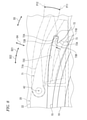
- FIG. 10 shows a state in which the second case 20 is in the neutral position P20 with respect to the first case 10.
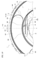
- FIG. 11 shows a state in which the second case 20 is rotated 360 degrees from the neutral position P20 to the first rotation direction D21 with respect to the first case 10.
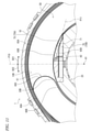
- FIG. 12 shows a state in which the second case 20 is rotated 720 degrees from the neutral position P20 to the first rotation direction D21 with respect to the first case 10.
- the electric cable 60 is composed of four flat cables 61, but FIGS. 10 to 12 simplify the electric cable 60.
- the second winding portion 60B of the electric cable 60 is wound around the outer peripheral surface 20B by about 2 to 3 turns. Therefore, the movable member 71 is urged inward in the radial direction by the electric cable 60. On the other hand, the movable member 71 is urged outward in the radial direction by the lead-out portion 60D of the electric cable 60, but the number of the second winding portions 60B arranged on the radial outer side of the movable member 71 is larger than the diameter of the movable member 71. It is larger than the number of out-licensing units 60D arranged inside the direction. Therefore, in a state where the second case 20 is in the neutral position P20 with respect to the first case 10, the movable member 71 is held at the first radial position P11 by the urging force of the electric cable 60.
- the movable member 71 can move to the first radial position P11 and the second radial position P12 according to the state of the electric cable 60.
- the urging force of the electric cable 60 for urging the movable member 71 toward the first radial position P11 becomes smaller.
- the urging force of the electric cable 60 to urge the movable member 71 toward the first radial position P11 becomes large.
- the second winding portion 60B of the electric cable 60 is wound around the outer peripheral surface 20B. Is reduced.
- the length of the second winding portion 60B wound around the outer peripheral surface 20B is reduced by the amount of the first electric cable 60. The length of the winding portion 60A wound around the inner peripheral surface 10B increases.
- the second case 20 when the second case 20 is rotated 360 degrees from the neutral position P20 to the first rotation direction D21 with respect to the first case 10, the second case 20 is wound around the outer peripheral surface 20B as compared with the neutral position P20.
- the number of 2 winding portions 60B is reduced.
- the urging force of the electric cable 60 inward in the radial direction weakens, and the movable member 71 unintentionally moves due to the minute movement of the movable member 71 with respect to the second case 20 due to individual differences in products, dimensional errors, and the like.
- the outer peripheral surface 20B is compared with the case where the second case 20 is rotated 360 degrees from the neutral position P20.
- the number of second winding portions 60B wound around is further reduced.
- the second case 20 rotates 720 degrees from the neutral position P20 to the first rotation direction D21 with respect to the first case 10
- the number of the second winding portions 60B wound around the outer peripheral surface 20B becomes zero.
- the movable member 71 is urged outward in the radial direction by the lead-out portion 60D of the electric cable 60.
- the movable member 71 when the movable member 71 is urged outward in the radial direction by the lead-out portion 60D of the electric cable 60 and the second case 20 is further rotated with respect to the first case 10, the movable member 71 is movable.
- the protruding portion 71B of the member 71 comes into contact with the stopper surface 72A of the rotation limiting portion 72, and the rotation of the second case 20 with respect to the first case 10 in the first rotation direction D21 is stopped.
- the rotation angle of the second case 20 with respect to the first case 10 in the first rotation direction D21 is limited to approximately 720 degrees by the stopper structure 70.
- the rotary connector device 1 includes a first case 10, a second case 20, an electric cable 60, and a stopper structure 70.
- the first case 10 and the second case 20 are provided so as to be relatively rotatable around the rotation axis A1 and form a cable accommodating space 50 provided so as to surround the rotation axis A1.
- the electric cable 60 is provided in the cable accommodating space 50 so as to be wound in the circumferential direction D3 defined around the rotation axis A1.
- the stopper structure 70 is configured to limit the relative rotation of the first case 10 and the second case 20 to a predetermined rotation angle.
- the stopper structure 70 includes a movable member 71, a rotation limiting portion 72, and a guide portion 73.
- the movable member 71 is movable in the radial direction orthogonal to the rotation axis A1 between the first radial position P11 and the second radial position P12 with respect to the second case 20.
- the rotation limiting portion 72 is provided in the first case 10, and is peripheral to the movable member 71 so as to limit the relative rotation of the first case 10 and the second case 20 in a state where the movable member 71 is in the second radial position P12. It is possible to contact the direction D3.
- the guide portion 73 is provided in the first case 10 and can come into contact with the movable member 71 so as to guide the movable member 71 toward the first radial position P11.
- the guide portion 73 causes the movable member 71 to move to the first radial position P11. Will be guided to. Therefore, due to the minute movement of the movable member 71 with respect to the second case 20 due to individual differences in products, dimensional errors, etc., the movable member 71 comes into contact with the rotation limiting portion 72 in an unintended state, and the first case 10 and the second case 10 and the second case 20 are brought into contact with each other. It is possible to suppress the limitation of the relative rotation of the case 20.
- the rotation limiting portion 72 is arranged outside the guide portion 73 in the radial direction. As a result, a larger rotational force can be received by the rotation limiting portion 72, and the strength of the stopper structure 70 can be increased.
- the rotation limiting portion 72 includes the movable member 71 and the stopper surface 72A that can come into contact with the circumferential direction D3.
- the guide portion 73 projects from the stopper surface 72A in the circumferential direction D3. Therefore, the guide portion 73 can reliably guide the movable member 71 toward the first radial position P11.
- the guide portion 73 includes a guide surface 73A that is inclined with respect to the circumferential direction D3 when viewed along the rotation axis A1. Therefore, the guide surface 73A can more reliably guide the movable member 71 toward the first radial position P11.
- the guide portion 73 is configured to restrict the movable member 71 from moving toward the first radial position P11 while the movable member 71 is in the second radial position P12. Therefore, for example, the contact state between the movable member 71 and the rotation limiting portion 72 can be stabilized in a state where the movable member 71 is in contact with the rotation limiting portion 72 at the second radial position P12.
- the stopper structure 70 includes a stopper groove 72B into which the movable member 71 is inserted at least partially while the movable member 71 is in contact with the rotation limiting portion 72. Therefore, for example, in a state where the movable member 71 is in contact with the rotation limiting portion 72 at the second radial position P12, the contact state between the movable member 71 and the rotation limiting portion 72 can be further stabilized.
- the movable member 71 projects from the stopper body 71A rotatably connected to the second case 20 around the stopper rotation axis A2 and the stopper body 71A in the axial direction D1 defined along the rotation axis A1 to limit rotation.
- the portion 72 includes a protruding portion 71B that can come into contact with the circumferential direction D3.
- the stopper main body 71A includes a cable contact surface 75 that can come into contact with the electric cable 60 so as to receive a radial force from the electric cable 60 according to the state of the electric cable 60.
- the movable member 71 can be moved in the radial direction by using the electric cable 60, and the structure can be simplified.
- the protrusion 71B is provided radially inside the cable contact surface 75 when viewed along the rotation axis A1. As a result, the protrusion 71B can be arranged outside the cable accommodating space 50. (10) The protruding portion 71B is arranged at a position radially separated from the rotation limiting portion 72 with the movable member 71 at the first radial position P11. Therefore, it is possible to reliably prevent the movable member 71 from unintentionally coming into contact with the rotation limiting portion 72. (11) The movable member 71 can move to the first radial position P11 and the second radial position P12 according to the state of the electric cable 60.
- the first case 10 includes an inner peripheral surface that partially forms the cable accommodating space 50.
- the second case 20 includes an outer peripheral surface provided on the radial inner side of the inner peripheral surface and partially forming the cable accommodating space 50.
- the electric cable 60 includes a first winding portion wound along the inner peripheral surface of the first case 10, a second winding portion wound along the outer peripheral surface of the second case 20, and a first winding portion and a second winding portion. It includes an intermediate portion provided between the portions and connecting the first winding portion to the second winding portion.
- the electric cable 60 accommodates the cable so that when the second case 20 rotates in the first rotation direction D21 with respect to the first case 10, the length of the second winding portion of the electric cable 60 wound around the outer peripheral surface decreases. It is provided in the space 50.
- the electric cable 60 when the second case 20 rotates in the second rotation direction D22 opposite to the first rotation direction D21 with respect to the first case 10, the second winding portion of the electric cable 60 is wound around the outer peripheral surface. It is provided in the cable accommodating space 50 so as to increase the length.
- the urging force of the electric cable 60 for urging the movable member 71 toward the first radial position P11 becomes smaller.
- the first case 10 is a stator configured to be fixed to the vehicle body.
- the second case 20 is a rotator that can rotate around the rotation axis A1 with respect to the stator 10.
- the movable member 71 is rotatably connected to the rotator around the stopper rotation axis A2.
- the rotation limiting portion 72 is provided on the stator 10. Therefore, the rotation limiting portion 72 provided on the stator 10 can receive a larger force and increase the strength of the stopper structure 70.
- ordinal numbers such as “first” and “second” are merely terms for identifying the composition and have no other meaning (for example, a specific order). For example, the existence of the “first element” does not imply that the “second element” exists, and the existence of the “second element” does not imply the existence of the “first element”. It does not imply that the "element” exists.
- the expression "at least one of A and B” in the present disclosure includes, for example, any of (1) A only, (2) B only, and (3) both A and B. ..
- the expression "at least one of A, B and C” is, for example, (1) A only, (2) B only, (3) C only, (4) A and B, (5) B and C, All of (6) A and C and (7) A, B and C are included.
- the expression "at least one of A and B" is not construed as "at least one of A and at least one of B".
- Rotating connector device 10 First case, stator 10B: Inner peripheral surface 15: Circular groove 20: Second case, rotator 20B: Outer peripheral surface 30: First electric connector 40: Second electric connector 50: Cable accommodation space 60: Electric cable 60A: First winding part 60B: Second winding part 60C: Intermediate part 60D: Leading part 70: Stopper structure 71 : Movable member 71A: Stopper body 71B: Protruding part 72: Rotation limiting part 72A: Stopper surface 72B: Stopper groove 72C: Introducing surface 73: Guide part 73A: Guide surface 73B: Limiting surface 75: Cable contact surface 75A: First cable Contact surface 75B: Second cable contact surface A1: Rotation axis A2: Stopper rotation axis D1: Axial direction D21: First rotation direction D22: Second rotation direction D3: Circumferential direction D4: Radial direction P11: First radial position P12 : 2nd radial position P13: Intermediate position
Landscapes
- Engineering & Computer Science (AREA)
- Mechanical Engineering (AREA)
- Electric Cable Arrangement Between Relatively Moving Parts (AREA)
- Chemical & Material Sciences (AREA)
- Combustion & Propulsion (AREA)
- Transportation (AREA)
- Steering Controls (AREA)
- Details Of Connecting Devices For Male And Female Coupling (AREA)
Abstract
Description
(1)回転コネクタ装置1は、第1ケース10、第2ケース20、電気ケーブル60、およびストッパ構造70を備える。第1ケース10および第2ケース20は、回転軸線A1回りに互いに相対回転可能に設けられ、回転軸線A1を取り囲むように設けられるケーブル収容空間50を形成する。電気ケーブル60は、回転軸線A1回りに定義される周方向D3に巻かれるようにケーブル収容空間50内に設けられる。ストッパ構造70は、第1ケース10および第2ケース20の相対回転を所定の回転角度に制限するように構成される。ストッパ構造70は、可動部材71、回転制限部72、および案内部73を含む。可動部材71は、第2ケース20に対して第1径方向位置P11および第2径方向位置P12の間を回転軸線A1に直交する径方向に移動可能である。回転制限部72は、第1ケース10に設けられ、可動部材71が第2径方向位置P12にある状態で第1ケース10および第2ケース20の相対回転を制限するように可動部材71と周方向D3に接触可能である。案内部73は、第1ケース10に設けられ、可動部材71を第1径方向位置P11の方へ案内するように可動部材71と接触可能である。
(2)回転制限部72は、案内部73の径方向外側に配置される。これにより、より大きな回転力を回転制限部72で受けることができ、ストッパ構造70の強度を高めることができる。
(3)回転制限部72は、可動部材71と周方向D3に接触可能なストッパ面72Aを含む。案内部73は、ストッパ面72Aから周方向D3に突出する。したがって、案内部73により可動部材71を第1径方向位置P11の方へ確実に案内できる。
(4)案内部73は、回転軸線A1に沿って見た場合に周方向D3に対して傾斜する案内面73Aを含む。したがって、案内面73Aにより可動部材71を第1径方向位置P11の方へより確実に案内できる。
(5)案内部73は、可動部材71が第2径方向位置P12にある状態で可動部材71が第1径方向位置P11の方へ移動するのを制限するように構成される。したがって、例えば、可動部材71が第2径方向位置P12において回転制限部72と接触する状態で、可動部材71と回転制限部72との接触状態を安定させることができる。
(6)ストッパ構造70は、可動部材71が回転制限部72と接触する状態で可動部材71が少なくとも部分的に挿入されるストッパ溝72Bを含む。したがって、例えば、可動部材71が第2径方向位置P12において回転制限部72と接触する状態で、可動部材71と回転制限部72との接触状態をより安定させることができる。
(7)可動部材71は、ストッパ回転軸線A2回りに回転可能に第2ケース20に連結されるストッパ本体71Aと、ストッパ本体71Aから回転軸線A1に沿って定義される軸方向D1に突出し回転制限部72と周方向D3に接触可能な突出部71Bと、を含む。これにより、突出部71Bの形状や位置がストッパ本体71Aの形状や位置などの影響を受けにくくなり、可動部材71の設計の自由度が高まる。
(8)ストッパ本体71Aは、電気ケーブル60の状態に応じて電気ケーブル60から径方向の力を受けるように電気ケーブル60と接触可能なケーブル接触面75を含む。これにより、電気ケーブル60を利用して可動部材71を径方向に動かすことができ、構造の簡素化が可能となる。
(9)突出部71Bは、回転軸線A1に沿って見た場合にケーブル接触面75よりも径方向内側に設けられる。これにより、突出部71Bをケーブル収容空間50の外側に配置することができる。
(10)突出部71Bは、可動部材71が第1径方向位置P11にある状態で回転制限部72と径方向に離れた位置に配置される。したがって、意図せず可動部材71が回転制限部72に接触するのを確実に抑制できる。
(11)可動部材71は、電気ケーブル60の状態に応じて第1径方向位置P11および第2径方向位置P12に移動可能である。これにより、電気ケーブル60を利用して可動部材71を第1径方向位置P11および第2径方向位置P12の方へ動かすことができ、構造の簡素化が可能となる。
(12)第1ケース10は、ケーブル収容空間50を部分的に形成する内周面を含む。第2ケース20は、内周面の径方向内側に設けられケーブル収容空間50を部分的に形成する外周面を含む。電気ケーブル60は、第1ケース10の内周面に沿って巻かれる第1巻き部と、第2ケース20の外周面に沿って巻かれる第2巻き部と、第1巻き部と第2巻き部との間に設けられ第1巻き部を第2巻き部に連結する中間部と、を含む。電気ケーブル60は、第2ケース20が第1ケース10に対して第1回転方向D21に回転すると電気ケーブル60の第2巻き部が外周面に巻かれている長さが減るように、ケーブル収容空間50内に設けられる。電気ケーブル60は、第2ケース20が第1ケース10に対して第1回転方向D21とは反対の第2回転方向D22に回転すると電気ケーブル60の第2巻き部が外周面に巻かれている長さが増えるように、ケーブル収容空間50内に設けられる。第2ケース20が第1ケース10に対して第1回転方向D21に回転すると、電気ケーブル60が可動部材71を第1径方向位置P11の方に付勢する付勢力が小さくなる。第2ケース20が第1ケース10に対して第2回転方向D22に回転すると、電気ケーブル60が可動部材71を第1径方向位置P11の方に付勢する付勢力が大きくなる。したがって、第1ケース10および第2ケース20の相対回転を利用して可動部材71を第1径方向位置P11および第2径方向位置P12の方へ動かすことができ、構造の簡素化が可能となる。
(13)第1ケース10は、車体に固定されるように構成されるステータである。第2ケース20は、ステータ10に対して回転軸線A1回りに回転可能なロテータである。可動部材71は、ストッパ回転軸線A2回りに回転可能にロテータに連結される。回転制限部72は、ステータ10に設けられる。したがって、ステータ10に設けられる回転制限部72により、より大きな力を受けることができ、ストッパ構造70の強度を高めることができる。
10 :第1ケース、ステータ(stator)
10B :内周面
15 :環状溝
20 :第2ケース、ロテータ(rotator)
20B :外周面
30 :第1電気コネクタ
40 :第2電気コネクタ
50 :ケーブル収容空間
60 :電気ケーブル
60A :第1巻き部
60B :第2巻き部
60C :中間部
60D :導出部
70 :ストッパ構造
71 :可動部材
71A :ストッパ本体
71B :突出部
72 :回転制限部
72A :ストッパ面
72B :ストッパ溝
72C :導入面
73 :案内部
73A :案内面
73B :制限面
75 :ケーブル接触面
75A :第1ケーブル接触面
75B :第2ケーブル接触面
A1 :回転軸線
A2 :ストッパ回転軸線
D1 :軸方向
D21 :第1回転方向
D22 :第2回転方向
D3 :周方向
D4 :径方向
P11 :第1径方向位置
P12 :第2径方向位置
P13 :中間位置
Claims (13)
- 回転軸線回りに互いに相対回転可能に設けられ、前記回転軸線を取り囲むように設けられるケーブル収容空間を形成する第1ケースおよび第2ケースと、
前記回転軸線回りに定義される周方向に巻かれるように前記ケーブル収容空間内に設けられる電気ケーブルと、
前記第1ケースおよび前記第2ケースの相対回転を所定の回転角度に制限するように構成されるストッパ構造と、を備え、
前記ストッパ構造は、
前記第2ケースに対して第1径方向位置および第2径方向位置の間を前記回転軸線に直交する径方向に移動可能な可動部材と、
前記第1ケースに設けられ、前記可動部材が前記第2径方向位置にある状態で前記第1ケースおよび前記第2ケースの相対回転を制限するように前記可動部材と前記周方向に接触可能な回転制限部と、
前記第1ケースに設けられ、前記可動部材を前記第1径方向位置の方へ案内するように前記可動部材と接触可能な案内部と、を含む、
回転コネクタ装置。 - 前記回転制限部は、前記案内部の径方向外側に配置される、
請求項1に記載の回転コネクタ装置。 - 前記回転制限部は、前記可動部材と前記周方向に接触可能なストッパ面を含み、
前記案内部は、前記ストッパ面から前記周方向に突出する、
請求項1または2に記載の回転コネクタ装置。 - 前記案内部は、前記回転軸線に沿って見た場合に前記周方向に対して傾斜する案内面を含む、
請求項1~3のいずれか1項に記載の回転コネクタ装置。 - 前記案内部は、前記可動部材が前記第2径方向位置にある状態で前記可動部材が前記第1径方向位置の方へ移動するのを制限するように構成される、
請求項1~4のいずれか1項に記載の回転コネクタ装置。 - 前記ストッパ構造は、前記可動部材が前記回転制限部と接触する状態で前記可動部材が少なくとも部分的に挿入されるストッパ溝を含む、
請求項1~5のいずれか1項に記載の回転コネクタ装置。 - 前記可動部材は、ストッパ回転軸線回りに回転可能に前記第2ケースに連結されるストッパ本体と、前記ストッパ本体から前記回転軸線に沿って定義される軸方向に突出し前記回転制限部と前記周方向に接触可能な突出部と、を含む、
請求項1~6のいずれか1項に記載の回転コネクタ装置。 - 前記ストッパ本体は、前記電気ケーブルの状態に応じて前記電気ケーブルから前記径方向の力を受けるように前記電気ケーブルと接触可能なケーブル接触面を含む、
請求項7に記載の回転コネクタ装置。 - 前記突出部は、前記回転軸線に沿って見た場合に前記ケーブル接触面よりも径方向内側に設けられる、
請求項8に記載の回転コネクタ装置。 - 前記突出部は、前記可動部材が前記第1径方向位置にある状態で前記回転制限部と径方向に離れた位置に配置される、
請求項1~9のいずれか1項に記載の回転コネクタ装置。 - 前記可動部材は、前記電気ケーブルの状態に応じて前記第1径方向位置および前記第2径方向位置に移動可能である、
請求項1~10のいずれか1項に記載の回転コネクタ装置。 - 前記第1ケースは、前記ケーブル収容空間を部分的に形成する内周面を含み、
前記第2ケースは、前記内周面の径方向内側に設けられ前記ケーブル収容空間を部分的に形成する外周面を含み、
前記電気ケーブルは、前記第1ケースの前記内周面に沿って巻かれる第1巻き部と、前記第2ケースの前記外周面に沿って巻かれる第2巻き部と、前記第1巻き部と前記第2巻き部との間に設けられ前記第1巻き部を前記第2巻き部に連結する中間部と、を含み、
前記電気ケーブルは、前記第2ケースが前記第1ケースに対して第1回転方向に回転すると前記電気ケーブルの前記第2巻き部が前記外周面に巻かれている長さが減るように、前記ケーブル収容空間内に設けられ、
前記電気ケーブルは、前記第2ケースが前記第1ケースに対して第1回転方向とは反対の第2回転方向に回転すると前記電気ケーブルの前記第2巻き部が前記外周面に巻かれている長さが増えるように、前記ケーブル収容空間内に設けられ、
前記第2ケースが前記第1ケースに対して前記第1回転方向に回転すると、前記電気ケーブルが前記可動部材を前記第1径方向位置の方に付勢する付勢力が小さくなり、
前記第2ケースが前記第1ケースに対して前記第2回転方向に回転すると、前記電気ケーブルが前記可動部材を前記第1径方向位置の方に付勢する前記付勢力が大きくなる、
請求項1~11のいずれか1項に記載の回転コネクタ装置。 - 前記第1ケースは、車体に固定されるように構成されるステータである、
前記第2ケースは、前記ステータに対して前記回転軸線回りに回転可能なロテータであり、
前記可動部材は、ストッパ回転軸線回りに回転可能に前記ロテータに連結され、
前記回転制限部は、前記ステータに設けられる、
請求項1~12のいずれか1項に記載の回転コネクタ装置。
Priority Applications (5)
| Application Number | Priority Date | Filing Date | Title |
|---|---|---|---|
| CN202180047328.7A CN115917891A (zh) | 2020-07-13 | 2021-07-01 | 旋转连接器装置 |
| EP21841656.8A EP4178049A4 (en) | 2020-07-13 | 2021-07-01 | Rotational connector device |
| KR1020237004596A KR102803691B1 (ko) | 2020-07-13 | 2021-07-01 | 회전 커넥터 장치 |
| JP2022536248A JP7654660B2 (ja) | 2020-07-13 | 2021-07-01 | 回転コネクタ装置 |
| US18/096,496 US12334695B2 (en) | 2020-07-13 | 2023-01-12 | Rotary connector device |
Applications Claiming Priority (2)
| Application Number | Priority Date | Filing Date | Title |
|---|---|---|---|
| JP2020120064 | 2020-07-13 | ||
| JP2020-120064 | 2020-07-13 |
Related Child Applications (1)
| Application Number | Title | Priority Date | Filing Date |
|---|---|---|---|
| US18/096,496 Continuation US12334695B2 (en) | 2020-07-13 | 2023-01-12 | Rotary connector device |
Publications (1)
| Publication Number | Publication Date |
|---|---|
| WO2022014349A1 true WO2022014349A1 (ja) | 2022-01-20 |
Family
ID=79554751
Family Applications (1)
| Application Number | Title | Priority Date | Filing Date |
|---|---|---|---|
| PCT/JP2021/025012 Ceased WO2022014349A1 (ja) | 2020-07-13 | 2021-07-01 | 回転コネクタ装置 |
Country Status (6)
| Country | Link |
|---|---|
| US (1) | US12334695B2 (ja) |
| EP (1) | EP4178049A4 (ja) |
| JP (1) | JP7654660B2 (ja) |
| KR (1) | KR102803691B1 (ja) |
| CN (1) | CN115917891A (ja) |
| WO (1) | WO2022014349A1 (ja) |
Cited By (1)
| Publication number | Priority date | Publication date | Assignee | Title |
|---|---|---|---|---|
| WO2024012466A1 (zh) * | 2022-07-12 | 2024-01-18 | 杭州巨星科技股份有限公司 | 一种疏通器 |
Families Citing this family (1)
| Publication number | Priority date | Publication date | Assignee | Title |
|---|---|---|---|---|
| KR20230035637A (ko) | 2020-07-15 | 2023-03-14 | 후루카와 덴키 고교 가부시키가이샤 | 회전 커넥터 장치 |
Citations (3)
| Publication number | Priority date | Publication date | Assignee | Title |
|---|---|---|---|---|
| JPH02139875U (ja) * | 1989-04-26 | 1990-11-22 | ||
| JP2002218639A (ja) | 2001-01-15 | 2002-08-02 | Furukawa Electric Co Ltd:The | 回転コネクタ |
| WO2014157233A1 (ja) * | 2013-03-27 | 2014-10-02 | アルプス電気株式会社 | 回転コネクタ |
Family Cites Families (8)
| Publication number | Priority date | Publication date | Assignee | Title |
|---|---|---|---|---|
| US1174942A (en) * | 1915-04-24 | 1916-03-07 | Graphite Lubricating Company | Antifriction-bearing and method of producing same. |
| JP2540938Y2 (ja) * | 1992-09-04 | 1997-07-09 | 古河電気工業株式会社 | 回転体と固定体間の伝送装置 |
| JP2002247746A (ja) * | 2001-02-15 | 2002-08-30 | Sumitomo Wiring Syst Ltd | ケーブルリール |
| JP3802370B2 (ja) * | 2001-05-08 | 2006-07-26 | アルプス電気株式会社 | 回転コネクタ |
| JP5076452B2 (ja) * | 2006-11-13 | 2012-11-21 | 富士通セミコンダクター株式会社 | 半導体装置の製造方法 |
| JP2009158169A (ja) * | 2007-12-25 | 2009-07-16 | Alps Electric Co Ltd | 回転コネクタ用リードブロックの製造方法 |
| JP5184716B2 (ja) * | 2010-11-19 | 2013-04-17 | 古河電気工業株式会社 | 回転コネクタ装置 |
| EP3783758B1 (en) * | 2018-05-28 | 2022-04-27 | Furukawa Electric Co., Ltd. | Rotary connector device and rotary body of rotary connector device |
-
2021
- 2021-07-01 JP JP2022536248A patent/JP7654660B2/ja active Active
- 2021-07-01 WO PCT/JP2021/025012 patent/WO2022014349A1/ja not_active Ceased
- 2021-07-01 CN CN202180047328.7A patent/CN115917891A/zh active Pending
- 2021-07-01 EP EP21841656.8A patent/EP4178049A4/en active Pending
- 2021-07-01 KR KR1020237004596A patent/KR102803691B1/ko active Active
-
2023
- 2023-01-12 US US18/096,496 patent/US12334695B2/en active Active
Patent Citations (3)
| Publication number | Priority date | Publication date | Assignee | Title |
|---|---|---|---|---|
| JPH02139875U (ja) * | 1989-04-26 | 1990-11-22 | ||
| JP2002218639A (ja) | 2001-01-15 | 2002-08-02 | Furukawa Electric Co Ltd:The | 回転コネクタ |
| WO2014157233A1 (ja) * | 2013-03-27 | 2014-10-02 | アルプス電気株式会社 | 回転コネクタ |
Non-Patent Citations (1)
| Title |
|---|
| See also references of EP4178049A4 |
Cited By (1)
| Publication number | Priority date | Publication date | Assignee | Title |
|---|---|---|---|---|
| WO2024012466A1 (zh) * | 2022-07-12 | 2024-01-18 | 杭州巨星科技股份有限公司 | 一种疏通器 |
Also Published As
| Publication number | Publication date |
|---|---|
| CN115917891A (zh) | 2023-04-04 |
| EP4178049A4 (en) | 2023-12-20 |
| KR20230029998A (ko) | 2023-03-03 |
| US20230170656A1 (en) | 2023-06-01 |
| EP4178049A1 (en) | 2023-05-10 |
| JP7654660B2 (ja) | 2025-04-01 |
| KR102803691B1 (ko) | 2025-05-09 |
| US12334695B2 (en) | 2025-06-17 |
| JPWO2022014349A1 (ja) | 2022-01-20 |
Similar Documents
| Publication | Publication Date | Title |
|---|---|---|
| JP6868610B2 (ja) | 回転コネクタ装置 | |
| EP1094570B1 (en) | Rotating connector | |
| EP2597734B1 (en) | Rotary connector device | |
| CN102823083B (zh) | 旋转连接器装置 | |
| WO2022014349A1 (ja) | 回転コネクタ装置 | |
| JP5871438B2 (ja) | 回転コネクタ | |
| CN103222129B (zh) | 旋转连接器装置 | |
| CN102823082A (zh) | 旋转连接器装置 | |
| JP5624972B2 (ja) | 回転コネクタ装置 | |
| CN111033667A (zh) | 限位开关 | |
| CN111033668B (zh) | 限位开关 | |
| US12470029B2 (en) | Rotary connector device | |
| JP7640356B2 (ja) | 回転コネクタ装置 | |
| JP7717573B2 (ja) | 回転コネクタ装置 | |
| JP7640368B2 (ja) | 回転コネクタ装置およびステアリング装置 | |
| JP7558895B2 (ja) | 回転コネクタ装置およびステアリング装置 | |
| KR102700909B1 (ko) | 회전 커넥터 장치 및 회전 커넥터 장치용 플랫 케이블 조립체 | |
| EP1806812B1 (en) | Rotary connector | |
| JP2024121621A (ja) | ワイヤーハーネス連結部材および回転コネクタ装置 | |
| WO2024204523A1 (ja) | 回転コネクタ装置 | |
| JP2019016497A (ja) | 回転コネクタ装置 | |
| CN111066111B (zh) | 限位开关 | |
| JP2025095779A (ja) | 回転コネクタ装置 | |
| KR20250065649A (ko) | 회전 커넥터 장치 및 차량 탑재 장치 | |
| KR20210083530A (ko) | 자동차의 조향장치 |
Legal Events
| Date | Code | Title | Description |
|---|---|---|---|
| 121 | Ep: the epo has been informed by wipo that ep was designated in this application |
Ref document number: 21841656 Country of ref document: EP Kind code of ref document: A1 |
|
| ENP | Entry into the national phase |
Ref document number: 2022536248 Country of ref document: JP Kind code of ref document: A |
|
| ENP | Entry into the national phase |
Ref document number: 2021841656 Country of ref document: EP Effective date: 20230201 |
|
| ENP | Entry into the national phase |
Ref document number: 20237004596 Country of ref document: KR Kind code of ref document: A |
|
| NENP | Non-entry into the national phase |
Ref country code: DE |