WO2022018814A1 - 車載アクチュエータ制御方法、及び車載アクチュエータ制御装置 - Google Patents
車載アクチュエータ制御方法、及び車載アクチュエータ制御装置 Download PDFInfo
- Publication number
- WO2022018814A1 WO2022018814A1 PCT/JP2020/028172 JP2020028172W WO2022018814A1 WO 2022018814 A1 WO2022018814 A1 WO 2022018814A1 JP 2020028172 W JP2020028172 W JP 2020028172W WO 2022018814 A1 WO2022018814 A1 WO 2022018814A1
- Authority
- WO
- WIPO (PCT)
- Prior art keywords
- vehicle
- state
- background noise
- value
- noise
- Prior art date
- Legal status (The legal status is an assumption and is not a legal conclusion. Google has not performed a legal analysis and makes no representation as to the accuracy of the status listed.)
- Ceased
Links
Images






Classifications
-
- B—PERFORMING OPERATIONS; TRANSPORTING
- B60—VEHICLES IN GENERAL
- B60W—CONJOINT CONTROL OF VEHICLE SUB-UNITS OF DIFFERENT TYPE OR DIFFERENT FUNCTION; CONTROL SYSTEMS SPECIALLY ADAPTED FOR HYBRID VEHICLES; ROAD VEHICLE DRIVE CONTROL SYSTEMS FOR PURPOSES NOT RELATED TO THE CONTROL OF A PARTICULAR SUB-UNIT
- B60W20/00—Control systems specially adapted for hybrid vehicles
- B60W20/10—Controlling the power contribution of each of the prime movers to meet required power demand
- B60W20/15—Control strategies specially adapted for achieving a particular effect
- B60W20/17—Control strategies specially adapted for achieving a particular effect for noise reduction
-
- B—PERFORMING OPERATIONS; TRANSPORTING
- B60—VEHICLES IN GENERAL
- B60W—CONJOINT CONTROL OF VEHICLE SUB-UNITS OF DIFFERENT TYPE OR DIFFERENT FUNCTION; CONTROL SYSTEMS SPECIALLY ADAPTED FOR HYBRID VEHICLES; ROAD VEHICLE DRIVE CONTROL SYSTEMS FOR PURPOSES NOT RELATED TO THE CONTROL OF A PARTICULAR SUB-UNIT
- B60W10/00—Conjoint control of vehicle sub-units of different type or different function
- B60W10/04—Conjoint control of vehicle sub-units of different type or different function including control of propulsion units
- B60W10/06—Conjoint control of vehicle sub-units of different type or different function including control of propulsion units including control of combustion engines
-
- B—PERFORMING OPERATIONS; TRANSPORTING
- B60—VEHICLES IN GENERAL
- B60W—CONJOINT CONTROL OF VEHICLE SUB-UNITS OF DIFFERENT TYPE OR DIFFERENT FUNCTION; CONTROL SYSTEMS SPECIALLY ADAPTED FOR HYBRID VEHICLES; ROAD VEHICLE DRIVE CONTROL SYSTEMS FOR PURPOSES NOT RELATED TO THE CONTROL OF A PARTICULAR SUB-UNIT
- B60W20/00—Control systems specially adapted for hybrid vehicles
- B60W20/40—Controlling the engagement or disengagement of prime movers, e.g. for transition between prime movers
-
- B—PERFORMING OPERATIONS; TRANSPORTING
- B60—VEHICLES IN GENERAL
- B60W—CONJOINT CONTROL OF VEHICLE SUB-UNITS OF DIFFERENT TYPE OR DIFFERENT FUNCTION; CONTROL SYSTEMS SPECIALLY ADAPTED FOR HYBRID VEHICLES; ROAD VEHICLE DRIVE CONTROL SYSTEMS FOR PURPOSES NOT RELATED TO THE CONTROL OF A PARTICULAR SUB-UNIT
- B60W40/00—Estimation or calculation of non-directly measurable driving parameters for road vehicle drive control systems not related to the control of a particular sub unit, e.g. by using mathematical models
- B60W40/02—Estimation or calculation of non-directly measurable driving parameters for road vehicle drive control systems not related to the control of a particular sub unit, e.g. by using mathematical models related to ambient conditions
- B60W40/06—Road conditions
-
- B—PERFORMING OPERATIONS; TRANSPORTING
- B60—VEHICLES IN GENERAL
- B60K—ARRANGEMENT OR MOUNTING OF PROPULSION UNITS OR OF TRANSMISSIONS IN VEHICLES; ARRANGEMENT OR MOUNTING OF PLURAL DIVERSE PRIME-MOVERS IN VEHICLES; AUXILIARY DRIVES FOR VEHICLES; INSTRUMENTATION OR DASHBOARDS FOR VEHICLES; ARRANGEMENTS IN CONNECTION WITH COOLING, AIR INTAKE, GAS EXHAUST OR FUEL SUPPLY OF PROPULSION UNITS IN VEHICLES
- B60K6/00—Arrangement or mounting of plural diverse prime-movers for mutual or common propulsion, e.g. hybrid propulsion systems comprising electric motors and internal combustion engines
- B60K6/20—Arrangement or mounting of plural diverse prime-movers for mutual or common propulsion, e.g. hybrid propulsion systems comprising electric motors and internal combustion engines the prime-movers consisting of electric motors and internal combustion engines, e.g. HEVs
- B60K6/42—Arrangement or mounting of plural diverse prime-movers for mutual or common propulsion, e.g. hybrid propulsion systems comprising electric motors and internal combustion engines the prime-movers consisting of electric motors and internal combustion engines, e.g. HEVs characterised by the architecture of the hybrid electric vehicle
- B60K6/46—Series type
-
- B—PERFORMING OPERATIONS; TRANSPORTING
- B60—VEHICLES IN GENERAL
- B60W—CONJOINT CONTROL OF VEHICLE SUB-UNITS OF DIFFERENT TYPE OR DIFFERENT FUNCTION; CONTROL SYSTEMS SPECIALLY ADAPTED FOR HYBRID VEHICLES; ROAD VEHICLE DRIVE CONTROL SYSTEMS FOR PURPOSES NOT RELATED TO THE CONTROL OF A PARTICULAR SUB-UNIT
- B60W50/00—Details of control systems for road vehicle drive control not related to the control of a particular sub-unit, e.g. process diagnostic or vehicle driver interfaces
- B60W2050/0001—Details of the control system
- B60W2050/0043—Signal treatments, identification of variables or parameters, parameter estimation or state estimation
- B60W2050/005—Sampling
-
- B—PERFORMING OPERATIONS; TRANSPORTING
- B60—VEHICLES IN GENERAL
- B60W—CONJOINT CONTROL OF VEHICLE SUB-UNITS OF DIFFERENT TYPE OR DIFFERENT FUNCTION; CONTROL SYSTEMS SPECIALLY ADAPTED FOR HYBRID VEHICLES; ROAD VEHICLE DRIVE CONTROL SYSTEMS FOR PURPOSES NOT RELATED TO THE CONTROL OF A PARTICULAR SUB-UNIT
- B60W2420/00—Indexing codes relating to the type of sensors based on the principle of their operation
- B60W2420/54—Audio sensitive means, e.g. ultrasound
-
- B—PERFORMING OPERATIONS; TRANSPORTING
- B60—VEHICLES IN GENERAL
- B60W—CONJOINT CONTROL OF VEHICLE SUB-UNITS OF DIFFERENT TYPE OR DIFFERENT FUNCTION; CONTROL SYSTEMS SPECIALLY ADAPTED FOR HYBRID VEHICLES; ROAD VEHICLE DRIVE CONTROL SYSTEMS FOR PURPOSES NOT RELATED TO THE CONTROL OF A PARTICULAR SUB-UNIT
- B60W2510/00—Input parameters relating to a particular sub-units
- B60W2510/18—Braking system
-
- B—PERFORMING OPERATIONS; TRANSPORTING
- B60—VEHICLES IN GENERAL
- B60W—CONJOINT CONTROL OF VEHICLE SUB-UNITS OF DIFFERENT TYPE OR DIFFERENT FUNCTION; CONTROL SYSTEMS SPECIALLY ADAPTED FOR HYBRID VEHICLES; ROAD VEHICLE DRIVE CONTROL SYSTEMS FOR PURPOSES NOT RELATED TO THE CONTROL OF A PARTICULAR SUB-UNIT
- B60W2520/00—Input parameters relating to overall vehicle dynamics
- B60W2520/10—Longitudinal speed
-
- B—PERFORMING OPERATIONS; TRANSPORTING
- B60—VEHICLES IN GENERAL
- B60W—CONJOINT CONTROL OF VEHICLE SUB-UNITS OF DIFFERENT TYPE OR DIFFERENT FUNCTION; CONTROL SYSTEMS SPECIALLY ADAPTED FOR HYBRID VEHICLES; ROAD VEHICLE DRIVE CONTROL SYSTEMS FOR PURPOSES NOT RELATED TO THE CONTROL OF A PARTICULAR SUB-UNIT
- B60W2520/00—Input parameters relating to overall vehicle dynamics
- B60W2520/10—Longitudinal speed
- B60W2520/105—Longitudinal acceleration
-
- B—PERFORMING OPERATIONS; TRANSPORTING
- B60—VEHICLES IN GENERAL
- B60W—CONJOINT CONTROL OF VEHICLE SUB-UNITS OF DIFFERENT TYPE OR DIFFERENT FUNCTION; CONTROL SYSTEMS SPECIALLY ADAPTED FOR HYBRID VEHICLES; ROAD VEHICLE DRIVE CONTROL SYSTEMS FOR PURPOSES NOT RELATED TO THE CONTROL OF A PARTICULAR SUB-UNIT
- B60W2520/00—Input parameters relating to overall vehicle dynamics
- B60W2520/26—Wheel slip
-
- B—PERFORMING OPERATIONS; TRANSPORTING
- B60—VEHICLES IN GENERAL
- B60W—CONJOINT CONTROL OF VEHICLE SUB-UNITS OF DIFFERENT TYPE OR DIFFERENT FUNCTION; CONTROL SYSTEMS SPECIALLY ADAPTED FOR HYBRID VEHICLES; ROAD VEHICLE DRIVE CONTROL SYSTEMS FOR PURPOSES NOT RELATED TO THE CONTROL OF A PARTICULAR SUB-UNIT
- B60W2520/00—Input parameters relating to overall vehicle dynamics
- B60W2520/28—Wheel speed
-
- B—PERFORMING OPERATIONS; TRANSPORTING
- B60—VEHICLES IN GENERAL
- B60W—CONJOINT CONTROL OF VEHICLE SUB-UNITS OF DIFFERENT TYPE OR DIFFERENT FUNCTION; CONTROL SYSTEMS SPECIALLY ADAPTED FOR HYBRID VEHICLES; ROAD VEHICLE DRIVE CONTROL SYSTEMS FOR PURPOSES NOT RELATED TO THE CONTROL OF A PARTICULAR SUB-UNIT
- B60W2540/00—Input parameters relating to occupants
- B60W2540/10—Accelerator pedal position
-
- B—PERFORMING OPERATIONS; TRANSPORTING
- B60—VEHICLES IN GENERAL
- B60W—CONJOINT CONTROL OF VEHICLE SUB-UNITS OF DIFFERENT TYPE OR DIFFERENT FUNCTION; CONTROL SYSTEMS SPECIALLY ADAPTED FOR HYBRID VEHICLES; ROAD VEHICLE DRIVE CONTROL SYSTEMS FOR PURPOSES NOT RELATED TO THE CONTROL OF A PARTICULAR SUB-UNIT
- B60W2540/00—Input parameters relating to occupants
- B60W2540/12—Brake pedal position
-
- B—PERFORMING OPERATIONS; TRANSPORTING
- B60—VEHICLES IN GENERAL
- B60W—CONJOINT CONTROL OF VEHICLE SUB-UNITS OF DIFFERENT TYPE OR DIFFERENT FUNCTION; CONTROL SYSTEMS SPECIALLY ADAPTED FOR HYBRID VEHICLES; ROAD VEHICLE DRIVE CONTROL SYSTEMS FOR PURPOSES NOT RELATED TO THE CONTROL OF A PARTICULAR SUB-UNIT
- B60W2540/00—Input parameters relating to occupants
- B60W2540/18—Steering angle
-
- B—PERFORMING OPERATIONS; TRANSPORTING
- B60—VEHICLES IN GENERAL
- B60W—CONJOINT CONTROL OF VEHICLE SUB-UNITS OF DIFFERENT TYPE OR DIFFERENT FUNCTION; CONTROL SYSTEMS SPECIALLY ADAPTED FOR HYBRID VEHICLES; ROAD VEHICLE DRIVE CONTROL SYSTEMS FOR PURPOSES NOT RELATED TO THE CONTROL OF A PARTICULAR SUB-UNIT
- B60W2552/00—Input parameters relating to infrastructure
- B60W2552/35—Road bumpiness, e.g. potholes
Definitions
- the present invention relates to an in-vehicle actuator control method and an in-vehicle actuator control device.
- JP2015-38516A proposes a road surface condition estimation method that estimates the road surface condition from the time-series waveform of the vibration of the running tire.
- the time-series waveform of the tire vibration used for estimating the existing road surface condition described in JP2015-38516A includes minute vibrations caused by disturbance factors acting on the wheels (mechanical brake operation, wheel slip, etc.). Will be. Due to this disturbance element, it becomes difficult to extract a waveform component that truly represents the road surface state from the time-series waveform, so that the estimation accuracy of the road surface state is lowered.
- the present inventors estimate the magnitude of so-called road noise (noise generated by collision or friction between the road surface and the tire) from the road surface condition, and use it as a noise source at the timing when the road noise becomes large.
- road noise noise generated by collision or friction between the road surface and the tire
- an object of the present invention is to more reliably prevent the occupant from being uncomfortable due to the noise caused by the operation of the actuator in the vehicle.
- the vehicle control method of the present invention is an in-vehicle actuator control method for controlling the operation of an in-vehicle actuator that is a noise source, and the magnitude of road noise is quantified from the angular acceleration of the wheels of the vehicle or a parameter correlating with the angular acceleration.
- the estimation state determination process for determining whether or not the road noise value estimation state is the appropriate estimation state, and the road noise value and the estimation state.
- the background noise state determination process for determining whether the vehicle is in a relatively high background noise state or a relatively small background noise condition, and the vehicle is mounted according to the determined vehicle background noise condition. Includes an output adjustment step of adjusting the output of the actuator.
- the background noise state determination step when it is determined that the estimated state is the appropriate estimated state, the background noise of the vehicle is high or low depending on the magnitude of the road noise value and the predetermined threshold value. Determine if it is in a background noise state. When it is determined that the estimated state is not the appropriate estimated state, it is determined that the background noise of the vehicle is the low background noise state regardless of the road noise value. Further, in the output adjusting step, when it is determined that the background noise of the vehicle is in the high background noise state, the output of the vehicle-mounted actuator is set so that the noise associated with the operation of the vehicle-mounted actuator becomes relatively large. On the other hand, when it is determined that the background noise of the vehicle is in a low background noise state, the output of the vehicle-mounted actuator is set so that the noise associated with the operation of the vehicle-mounted actuator is relatively small.
- FIG. 1 is a diagram illustrating a configuration of a series hybrid vehicle in which an in-vehicle actuator control method according to an embodiment of the present invention is executed.
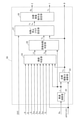
- FIG. 2 is a block diagram showing a function of a controller that executes a process according to an in-vehicle actuator control method.
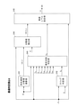
- FIG. 3 is a block diagram showing the function of the road surface determination unit.
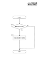
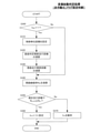
- FIG. 4A is a flowchart illustrating zero-point calibration of the front-rear G detection value in the slip determination process.
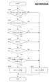
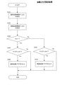
- FIG. 4B is a flowchart illustrating the setting of the slip flag in the slip determination process.
- FIG. 4C is a diagram illustrating the interrelationship between the front-rear G detection value, the front-rear G estimation value, and the vehicle slip.
- FIG. 4A is a flowchart illustrating zero-point calibration of the front-rear G detection value in the slip determination process.
- FIG. 4B is a flowchart illustrating the setting of the slip flag in the slip
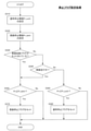
- FIG. 5 is a flowchart illustrating the estimation state determination process.
- FIG. 6A is a flowchart illustrating a process of setting the deactivation flag.
- FIG. 6B is a flowchart illustrating a process of clearing the deactivation flag.
- FIG. 7 is a flowchart illustrating the start flag setting process.
- FIG. 8 is a flowchart illustrating the stop flag setting process.
- FIG. 9 is a diagram showing an example of a map that determines a start threshold value and a stop threshold value.
- FIG. 10 is a diagram illustrating a control result according to the present embodiment.
- FIG. 1 is a block diagram illustrating a configuration common to a series hybrid vehicle (hereinafter, also simply referred to as “vehicle 100”) to which an in-vehicle actuator control method (particularly, an engine start / stop permission control method) according to the present embodiment is applied. Is.
- the vehicle 100 includes an engine (internal combustion engine) 1, a generator 2, a battery 3, an electric drive motor 4, a gear 5, an axle 6, wheels 7, and a controller 50.
- the vehicle-mounted actuator to be controlled includes the engine 1, the generator 2, and the drive motor 4.
- the engine 1 is mechanically connected to the generator 2 via a speed increaser (not shown), and the generator 2 is connected to the battery 3 so as to be able to transmit and receive power.
- the drive motor 4 is mechanically connected to the axle 6 via the gear 5, and the axle 6 is mechanically connected to the wheel 7.
- the driving force (or regenerative force) of the driving motor 4 is transmitted to the wheels 7 via the gear 5 and the axle 6. Therefore, the rotational speed of the wheels 7 (that is, acceleration or deceleration of the vehicle 100) is adjusted by the driving force (or regenerative force) of the driving motor 4.
- the amount of depression on the accelerator pedal mounted on the vehicle 100 is reduced.
- a regenerative brake that obtains braking force by regenerating the drive motor 4 according to the amount of decrease is mounted.
- the controller 50 is a computer programmed to supervise the control of the vehicle 100 including the processing related to the engine control method as the vehicle-mounted actuator control method according to the present embodiment. More specifically, the controller 50 has a hardware configuration including a central processing unit (CPU), a read-only memory (ROM), a random access memory (RAM), and an input / output interface (I / O interface), and a vehicle-mounted actuator control method. It is configured by providing a program for executing the processes constituting the above.
- the controller 50 may be realized by mounting the program on one computer hardware, or may be realized by distributing and mounting the program on a plurality of computer hardware. As a specific example, the function of the controller 50 can be realized by various computers such as a battery controller, a vehicle controller, and a motor controller mounted on the vehicle 100.
- the controller 50 executes the above engine control method by inputting various parameters received from various sensors (not shown) or other controllers. Specifically, the controller 50 has a detection value of the charge rate (SOC: State Of Charge) of the battery 3 (hereinafter, also referred to as “battery SOC”) and a detection value of the rotation speed of the wheels 7 (hereinafter, “wheel speed w”). (Also also referred to as), detection value of steering angle for steering mounted on vehicle 100 (hereinafter, also referred to as "steering angle ⁇ ”), detection of front-rear G (ratio of acceleration of vehicle 100 to forward or backward direction to gravity acceleration).
- SOC State Of Charge
- wheel speed w detection value of the rotation speed of the wheels 7
- VDC operation flag f vdc Vehicle Dynamics Control
- TCS Traffic Control System
- a flag indicating operation hereinafter, also referred to as “TCS operation flag f tcs "
- ABS Anti-lock Brake System
- ABS Anti-lock Brake System
- a flag indicating the effectiveness of communication (hereinafter, also referred to as “CAN effective flag f can "), and a flag indicating that the mechanical brake mounted on the vehicle 100 (operation on the brake pedal) is being performed (operation on the brake pedal).
- the "brake pedal operation flag f b "), the estimated value of the rotation speed of the drive motor 4 (hereinafter, also referred to as “motor rotation speed N m “), and the operation amount for the accelerator pedal mounted on the vehicle 100 (hereinafter, also referred to as “motor rotation speed N m”).
- motor rotation speed N m the operation amount for the accelerator pedal mounted on the vehicle 100
- the accelerator opening APO defines the magnitude of the output (mainly the electric power consumed by the traveling of the vehicle 100) required for the vehicle 100 (particularly the drive motor 4).
- the controller 50 executes power running control that demands a positive driving force from the drive motor 4 when the accelerator opening APO is equal to or more than a predetermined value, and when the accelerator opening APO is less than a predetermined value, the drive motor 4 is executed. Performs regenerative control that requires a negative driving force (ie, regenerative braking force).
- the output required for the vehicle 100 is a positive value
- the output required for the vehicle 100 is a negative value.
- the output (positive value or negative value) required for the vehicle 100 is referred to as "request output Pr".
- FIG. 2 is a block diagram illustrating the functions of the controller 50.
- the controller 50 includes a vehicle speed calculation unit 20, a target driving force calculation unit 22, a road surface determination unit 24, a sound vibration start determination unit 26, a start / stop flag setting unit 27, and a target power generation operating point.
- a setting unit 28 is provided.
- the vehicle speed calculation unit 20 calculates the vehicle speed v of the vehicle 100 based on the motor rotation speed N m.
- the vehicle speed calculation unit 20 outputs the calculated vehicle speed v to the target driving force calculation unit 22 and the road surface determination unit 24.
- the target driving force calculation unit 22 sets a target value of the driving force to the drive motor 4 based on the vehicle speed v from the vehicle speed calculation unit 20 and the accelerator opening APO (request output Pr) (hereinafter, “target motor torque T”). m ”) is calculated.
- the target driving force calculation unit 22 outputs the calculated target motor torque T m to the road surface determination unit 24 and the drive motor 4 (a motor inverter (not shown in more detail)).
- the road surface determination unit 24 has wheel speed w, steering angle ⁇ , front / rear G detection value, VDC operation flag f vdc , TCS operation flag f tcs , ABS operation flag f abs , CAN valid flag f can , brake pedal operation flag f b , And the road surface level Le is set based on the accelerator opening APO.
- the road surface level Le is a parameter that indexes the state of background noise of the vehicle 100 when the vehicle 100 is traveling.
- the road surface level Le is an estimated value obtained by quantifying the degree of road surface roughness calculated from the wheel speed w (more specifically, the angular acceleration A described later) (hereinafter, also referred to as “road noise value”), and It is set as an indexed parameter as to whether or not the estimated state of the road noise value is an appropriate estimated state. More specifically, the road surface level Le of the present embodiment is "0" corresponding to the case where the estimated state of the road noise value is not the appropriate estimated state, and "1" in which the magnitude of the road noise value is leveled at predetermined steps. It is composed of "4".
- the magnitude of the road surface level Le is used as an index for estimating whether the background noise of the vehicle 100 is relatively large or small. More specifically, when the road surface level Le is "0" to "2", the background noise state is estimated to be a low background noise state, and when the road surface level Le is "3" to "4", the background noise is estimated. Is presumed to be a high background noise condition.
- FIG. 3 is a block diagram showing the functions of the road surface determination unit 24.
- the road surface determination unit 24 includes an angular acceleration dispersion value calculation unit 241, a slip determination unit 242, an estimation state determination unit 243, a dispersion value correction unit 244, and a road surface level setting unit 245.
- the angular acceleration dispersion value calculation unit 241 calculates the dispersion value of the angular acceleration A of the wheel 7 (hereinafter, also referred to as “angular acceleration dispersion value var_A”) based on the wheel speed w. Specifically, the angular acceleration dispersion value calculation unit 241 obtains the angular acceleration A by calculating the first derivative of time with respect to the wheel speed w. Then, the angular acceleration dispersion value calculation unit 241 samples the angular acceleration A and sets the dispersion as the angular acceleration dispersion value var_A. Hereinafter, this dispersion value is also referred to as “angular acceleration dispersion value var_A”.
- the angular acceleration dispersion value var_A represents the variation of the angular acceleration A, which is a parameter that correlates with the roughness (road noise value) of the traveling road surface of the vehicle 100. Therefore, the angular acceleration dispersion value var_A can be used as an index for estimating the magnitude of the road noise value that determines the road surface level Le. Instead of the angular acceleration dispersion value var_A, an arbitrary statistic that correlates with the variation of the angular acceleration A such as the standard deviation and the root mean square may be calculated as an estimation index of the road noise value. Then, the angular acceleration dispersion value calculation unit 241 outputs the calculated angular acceleration dispersion value var_A to the dispersion value correction unit 244.
- the slip determination unit 242 executes the slip determination process by inputting the vehicle speed v and the front / rear G detection value from the vehicle speed calculation unit 20.
- the slip determination process is a slip flag f sl indicating that the vehicle 100 is slipping (or is predicted to occur) in a specific driving scene of the vehicle 100 (a low-speed running state immediately after starting from the time of stopping). It is a process to set.
- the slip determination process is executed as one of the elements for determining whether or not the estimated state of the road noise value is the appropriate estimated state.
- the slip determination process detects the occurrence of slip to the extent that the estimation accuracy of the road noise value based on the angular acceleration dispersion value var_A is lowered, although the vehicle 100 has not reached the slip accompanied by the operation of the TCS or VDC described above. It is executed from the viewpoint.
- FIGS. 4A and 4B are flowcharts for explaining the slip determination process.
- FIG. 4A shows the flow of processing related to the front-rear G input adjustment
- FIG. 4B shows the flow of processing related to the setting of the slip flag f sl.
- the processes according to FIGS. 4A and 4B can be executed in parallel with each other.
- step S110 the slip determination unit 242 determines whether or not the vehicle 100 is stopped. Specifically, the slip determination unit 242 counts the time during which the vehicle speed v becomes 0 or substantially 0, and when the time reaches a predetermined stop determination reference time, the vehicle 100 determines. Judge that the vehicle is stopped. When the slip determination unit 242 determines that the vehicle 100 is not stopped, the slip determination unit 242 ends this routine. On the other hand, when the slip determination unit 242 determines that the vehicle 100 is stopped, the process after step S120 is executed.
- step S120 the slip determination unit 242 executes 0-point calibration for the front-rear G detection value. That is, the slip determination unit 242 calculates a difference obtained by subtracting 0 from the front-rear G detection value acquired when the vehicle 100 is stopped and stores it in the storage area. Then, the slip determination unit 242 acquires a value obtained by subtracting the above difference from the detection value input from the G sensor (for example, strain gauge type or capacitance type) (not shown) at the subsequent control timing as the front-rear G detection value.
- the G sensor for example, strain gauge type or capacitance type
- step S130 the slip determination unit 242 determines whether or not the vehicle 100 is in a low-speed traveling state. Specifically, the slip determination unit 242 determines whether or not the vehicle speed v is equal to or less than a predetermined low speed determination threshold value.
- the slip determination unit 242 determines that the vehicle 100 is not in the low-speed traveling state
- the slip flag f sl is set to "0" and the present routine is terminated.
- the slip determination unit 242 executes the processes after step S140.
- step S140 the slip determination unit 242 calculates the front-rear G estimated value from the vehicle speed v. Specifically, the slip determination unit 242 calculates the acceleration a by time-differentiating the vehicle speed v, and calculates the front-rear G estimated value from the acceleration a.
- step S150 the slip determination unit 242 determines whether or not the difference between the front-rear G detection value calibrated by the value at the time of stopping and the front-rear G estimation value calculated from the vehicle speed v is larger than the predetermined reference value.
- the front-rear G estimated value estimated from the vehicle speed v (corresponding to the actual rotation speed of the wheel 7) actually acts on the vehicle 100 to the extent that it can be determined that the vehicle 100 is slipping. It is set to a suitable value from the viewpoint of whether or not it is separated from the front-rear G detection value based on the inertial force to be applied.
- FIG. 4C is a diagram illustrating the interrelationship between the front-rear G detection value, the front-rear G estimation value, and the slip of the vehicle 100.
- the horizontal axis shows the front-rear G estimated value ( corresponding to the time derivative value of the motor rotation speed N m )
- the vertical axis shows the front-rear G detection value.
- the broken line L1 and the solid line L2 represent the relationship between the front-rear G estimated value and the front-rear G detection value when slip does not occur and when slip occurs, respectively.
- the dotted line L3 represents a straight line in which the front-rear G estimated value and the front-rear G detection value are the same as each other.
- the slip determination unit 242 sets the slip flag f sl of the vehicle 100 to "1" when the determination result in step S150 is positive. On the other hand, the slip determination unit 242 sets the slip flag f sl of the vehicle 100 to "0" when the determination result in step S150 is negative.
- the slip determination unit 242 outputs the set slip flag f sl to the estimation state determination unit 243.
- the estimation state determination unit 243 has wheel speed w, vehicle speed v, target motor torque T m , brake pedal operation flag f b , accelerator opening APO, VDC operation flag f vdc , TCS operation flag f tcs , ABS operation flag f abs , With the CAN valid flag f can and the slip flag f sl as inputs, an estimation state determination process for determining whether or not the estimation state of the load noise value is an appropriate estimation state is executed.
- a proper estimation flag f op when the estimated state of the road noise value is proper estimated state is set to "1"
- the details of the estimation state determination process will be described.
- FIG. 5 is a flowchart illustrating the estimation state determination process.
- step S200 the estimation state determination unit 243 of the brake pedal operation flag f b , the accelerator off flag f ac , the VDC operation flag f vdc , the TCS operation flag f tcs , and the ABS operation flag f abs . It is determined whether or not all are set to "0".
- the accelerator off flag f ac is a flag set to "1" when it is determined that the accelerator pedal has not been operated (driving force required for the vehicle 100).
- the estimation state determination unit 243 sets the accelerator off flag f ac to "1" when the accelerator opening APO is equal to or less than a predetermined value, and when the accelerator opening APO exceeds the predetermined value. Set to "0".
- step S270 the appropriate estimation flag f op is set to "0", and this routine ends. That is, it corresponds to any of the cases where the operation on the brake pedal is detected, the operation on the accelerator pedal is not detected, the VDC is operating, the TCS is operating, and the ABS is operating. Then, since it is assumed that the calculated value of the angular acceleration A includes an error, it is determined that the estimated state of the road noise value is not appropriate.
- step S210 determines that all the flag values are "0" in the determination in step S200.
- step S210 the estimation state determination unit 243 determines whether or not the target motor torque T m is equal to or greater than the first torque threshold value T m_th1 and equal to or less than the second torque threshold value T m_th2. Then, if the result of the determination is negative, the estimation state determination unit 243 proceeds to step S270 , sets the appropriate estimation flag f op to “0”, and ends this routine. On the other hand, if the result of the determination is positive, the estimation state determination unit 243 executes the process of step S220.
- the first torque threshold value T m_th1 and the second torque threshold value T m_th2 are the lower limit value and the upper limit value of the target motor torque T m determined from the viewpoint of ensuring the estimation accuracy of the road noise value, respectively.
- the first torque threshold value T m_th1 and the second torque threshold value T m_th2 may be set to fixed values experimentally determined in advance, or may be set to variable values that change according to the running state of the vehicle 100 and the like. Is also good.
- the first torque threshold value T m_th1 and the second torque threshold value T m_th2 may be variable values according to the vehicle speed v. Further, for example, when the determination result of step S210 is negative at a certain control timing, a different first torque threshold value T m_th1 or second torque threshold value T m_th2 may be used for the determination at a later control timing. good. That is, predetermined hysteresis may be set for the first torque threshold value T m_th1 and the second torque threshold value T m_th2.
- step S220 the estimation state determination unit 243 determines whether or not the vehicle speed v is equal to or greater than the first vehicle speed threshold value v _th1 and equal to or less than the second vehicle speed threshold value v _th2. Then, if the result of the determination is negative, the estimation state determination unit 243 proceeds to step S270 , sets the appropriate estimation flag f op to “0”, and ends this routine. On the other hand, if the result of the determination is positive, the estimation state determination unit 243 executes the process of step S230.
- the first vehicle speed threshold value v _th1 and the second vehicle speed threshold value v _th2 are the lower limit value and the upper limit value of the vehicle speed v determined from the viewpoint of ensuring the estimation accuracy of the road noise value, respectively.
- the first vehicle speed threshold value v _th1 and the second vehicle speed threshold value v _th2 may be set to fixed values experimentally determined in advance, or may be set to variable values that change according to the running state of the vehicle 100 or the like. Is also good.
- predetermined hysteresis may be set for the first vehicle speed threshold value v _th1 and the second vehicle speed threshold value v _th2 in the same manner as in the first torque threshold value T m_th1 and the second torque threshold value T m_th2.
- step S230 the estimation state determination unit 243 determines whether or not the slip flag f sl set in the slip determination process is “0”. If the determination result is negative, the estimation state determination unit 243 proceeds to step S270 , sets the appropriate estimation flag f op to “0”, and ends this routine. That is, in this case, it is determined that there is a possibility that an error may be included in the calculated value of the angular acceleration A for estimating the road noise value due to the slip of the vehicle 100. On the other hand, when the estimation state determination unit 243 determines that the slip flag f sl is "0", the process of step S240 is executed.
- step S240 the estimation state determination unit 243 determines whether or not the CAN valid flag f can is “1”.
- the estimation state determination unit 243 determines that the CAN valid flag f can is not "1”
- it proceeds to step S270 , sets the appropriate estimation flag f op to "0", and ends this routine. That is, in this case, it is assumed that the input parameters such as the wheel speed w for calculating the angular acceleration A cannot be acquired normally, and it is judged that the estimation accuracy of the road noise value may decrease. ..
- the estimation state determination unit 243 determines that the CAN valid flag f can is "1"
- the process of step S250 is executed.
- step S250 the estimation state determination unit 243 determines whether or not the number of distributed samples is equal to or greater than a certain value. Specifically, the estimation state determination unit 243 is sufficient from the viewpoint of suitably calculating the above-mentioned angular acceleration dispersion value var_A from the timing at which it is detected that all the determination results in steps S200 to S250 are positive. It is determined whether or not a calculated value of a large number of angular accelerations A is obtained.
- step S270 the appropriate estimation flag f op is set to "0", and this routine is terminated. That is, in this case, the number of input data (more specifically, the number of wheel speeds w detected) for determining an appropriate angular acceleration dispersion value var_A from the viewpoint of ensuring the estimation accuracy of the road noise value is insufficient. It is determined and the appropriate estimation flag f op is set to "0".
- the process of step S260 is executed. In the determination in step S250, if the determination result is negative at a certain control timing, a delay is waited for a time until the number of distributed samples is secured (that is, until the determination result becomes affirmative). Processing may be adopted.
- step S260 the estimation state determination unit 243 sets the appropriate estimation flag f op to "1" and ends this routine. That is, in the present embodiment, when the determination results of steps S200 to S250 are all positive, it is determined that the estimation accuracy of the road noise value is secured to a certain level or higher, and the appropriate estimation flag f op is set to "1". Will be set to.
- the estimation state determination unit 243 outputs the set appropriate estimation flag f op to the road surface level setting unit 245.
- the dispersion value correction unit 244 corrects the angular acceleration dispersion value var_A by inputting the vehicle speed v, the steering angle ⁇ , and the angular acceleration dispersion value var_A. Specifically, the dispersion value correction unit 244 corrects the angular acceleration dispersion value var_A by using a table in which correction coefficients corresponding to the vehicle speed v and the steering angle ⁇ are determined. In particular, in the present embodiment, correction is performed so that the angular acceleration dispersion value var_A decreases as the vehicle speed v or the steering angle ⁇ increases.
- the wheel 7 slips slightly as compared with the case where the steering operation is not performed. Therefore, when the wheel 7 gets over the convex portion on an uneven road surface, the wheel 7 is used.
- the variance of the angular acceleration A tends to be larger than expected. Therefore, when the steering operation is performed, the angular acceleration dispersion value var_A is corrected to be reduced according to the magnitude of the vehicle speed v from the viewpoint of maintaining the estimation accuracy of the road noise value. Then, the dispersion value correction unit 244 outputs the corrected angular acceleration dispersion value var_A_c to the road surface level setting unit 245.
- the road surface level setting unit 245 sets the above-mentioned road surface level Le by inputting the angular acceleration dispersion value var_A_c and the appropriate estimation flag f op.
- the road surface level setting unit 245 sets the angular acceleration dispersion value var_A_c. Regardless, the road surface level Le is set to "0".
- the road surface level setting unit 245 has the road noise value (that is, the angular acceleration).
- the road surface level Le is set to "1" to "4" according to the magnitude of the dispersion value var_A_c). More specifically, the road surface level setting unit 245 sets three threshold values for the angular acceleration dispersion value var_A_c, and sets the road surface level Le as the road surface level Le within the range of the four angular acceleration dispersion values var_A_c defined by the three threshold values. 1 ”,“ 2 ”,“ 3 ”, and“ 4 ”are assigned, respectively. Then, the road surface level setting unit 245 outputs the set road surface level Le to the sound vibration start determination unit 26.
- the case where the road surface level Le is set to "0", "1", or “2" corresponds to a low background noise state, and the case where it is set to "3" or "4" may be set. Corresponds to a high background noise condition.
- the sound vibration start determination unit 26 the road surface level Le, as an input the proper estimation flag f op, and the vehicle speed v, in accordance with the magnitude of the road surface level Le, required output P r to start the engine 1 value (hereinafter, referred to as "initiation threshold P R_sth") or the value of the request output P r to stop the engine 1 (hereinafter, also referred to as “stop threshold value P R_eth”) control for regulating (hereinafter, "sound vibration start (Also referred to as "control”) Executes a sound vibration start determination process for determining whether or not to enable.
- the deactivation flag f no is set to "0" when the sound vibration start determination process should be executed, and set to "1" when the sound vibration start determination process should not be executed. Will be done.
- the initial value of the deactivation flag f no is set to either "0" or "1". It is assumed.
- FIG. 6A and 6B are flowcharts for explaining the sound vibration start determination process.
- FIG. 6A is a flowchart illustrating a determination (determination of setting the deactivation flag) for setting the deactivation flag f no to "1" in order to invalidate the operation of the sound vibration start control.
- FIG. 6B is a flowchart illustrating a determination (determination for clearing the deactivation flag) for clearing the deactivation flag f no set based on the process of FIG. 6A.
- step S300 the sound vibration start determination unit 26 determines whether or not the appropriate estimation flag f op is set to “1”. Then, when the sound vibration start determination unit 26 determines that the appropriateness estimation flag f op is "1", the process after step S310 is executed.
- step S310 the sound vibration start determination unit 26 sets the control unit distance d u .
- the control unit distance d u is a distance traveled by the vehicle 100 during a preset calculation period ⁇ t (for example, 10 ms). That is, the control unit distance d u is defined as a value obtained by multiplying the vehicle speed v by the calculation period ⁇ t, and is a variable amount according to the magnitude of the vehicle speed v.
- step S320 the sound vibration start determination unit 26 calculates the road surface determination integrated mileage D. Specifically, first, the sound vibration start determination unit 26 acquires the total mileage of the vehicle 100 from the start of the vehicle 100 (for example, the timing when the ignition switch is turned on) to the current control cycle. Then, the sound vibration start determination unit 26 travels at the time of proper estimation, which is the distance traveled by the vehicle 100 with the appropriate estimation flag f op set to "1" from the start of the vehicle 100 to the current control cycle. Calculate the distance. More specifically, the sound start determination unit 26 oscillation, by multiplying the proper estimation flag f op the control unit distance is the control number that is set to "1" d u, obtains the road-integrated travel distance D.
- step S330 the sound vibration start determination unit 26 calculates the rough road running integrated distance D ba. Specifically, in the sound vibration start determination unit 26, the appropriate estimation flag f op is set to "1" and the road surface level Le is set to "3" or "4" from the start of the vehicle 100 to the current control cycle. By multiplying the set number of controls by the control unit distance d u , the total distance traveled on rough roads D ba is obtained.
- step S340 the sound vibration start determination unit 26 calculates the rough road continuation rate R bc. Specifically, the sound vibration start determination unit 26 divides the rough road travel integrated distance D ba by the road surface determination integrated travel distance D to obtain the rough road continuation rate R bc .
- the sound vibration start determination unit 26 has a rough road continuation rate R bc equal to or higher than a predetermined rough road continuation rate threshold R bc_th in a state where the vehicle 100 has traveled over a predetermined specified mileage D _th. It is determined whether or not it has become. Specifically, the sound vibration start determination unit 26 calculates the specified mileage D _th by multiplying the predetermined number of controls by the control unit distance d u. Then, the sound vibration start determination unit 26 determines whether or not the rough road continuation rate R bc becomes equal to or greater than the rough road continuation rate threshold value R bc_th during the control cycle during traveling during the specified mileage D _ th.
- the rough road continuation rate threshold value R bc_th is whether the erroneous judgment continues in the judgment (judgment based on the road surface level Le) whether the traveling road of the vehicle 100 is a "bad road” or a "good road”. It is set to a suitable value from the viewpoint of determining whether or not it is.
- the rough road continuation rate threshold value R bc_th is set from the viewpoint of determining whether or not the operation time of the engine 1 becomes long and the fuel consumption is lowered when the operation of the sound vibration start control is enabled. More specifically, a state in which the erroneous determination that the vehicle 100 is traveling on a "rough road” is maintained for a certain period or more and the operation of the sound vibration start control is effective (the engine 1 is easy to start or difficult to stop). As the state) continues, it is assumed that the battery SOC rises and the engine 1 is frequently started and stopped. Therefore, the rough road continuation rate threshold value R bc_th is set to a suitable value from the viewpoint of suppressing such a situation.
- step S360 the deactivation flag f no. Is set to "1" to end this routine. That is, in this case, the sound vibration start control is invalidated.
- the sound vibration start determination unit 26 proceeds to step S370 and ends this routine while maintaining the deactivation flag f no.
- step S300 when the sound vibration start determination unit 26 determines that the appropriateness estimation flag f op is not "1" (determines that it is "0"), the process proceeds to the process of step S340. That is, when it is determined that the estimated state of the road noise value is not appropriate in this control cycle, the sound vibration start determination unit 26 calculates the road surface determination integrated mileage D in step S320 and the bad road in step S330. The rough road continuation rate R bc is calculated without executing the calculation of the total travel distance D ba.
- the distance related to the travel can be excluded from the calculation target of the road surface determination integrated mileage D, and the calculation is performed. It is possible to suppress a decrease in the accuracy of the rough road continuation rate R bc. More specifically, the distance in the state where the estimated state of the road noise value is not appropriate is added to the road surface determination integrated mileage D, so that the rough road continuation rate R bc is calculated lower than the expected value, resulting in an error. The phenomenon of switching between operation and non-operation of the sound vibration start control based on the determination is suppressed.
- the sound vibration start determination unit 26 resets the road surface determination integrated mileage D calculated in step S320 to 0 in the control cycle after the deactivation flag f no is switched from "1" to "0". It is preferable that it is configured to do so. As a result, in the scene where the vehicle 100 travels a relatively long distance from the start, the road surface determination integrated mileage D becomes a large value, and the evil obtained by dividing the rough road travel integrated distance D ba by the road surface determination integrated mileage D. It is suppressed that the rate of change of the road continuation rate R bc becomes small. As a result, the accuracy of erroneous determination based on the rough road continuation rate R bc can be further improved.
- step S380 the sound vibration start determination unit 26 determines whether or not the deactivation flag f no is set to “1”. Then, when the sound vibration start determination unit 26 determines that the deactivation flag f no is not "1" (determines that it is "0"), the sound vibration start determination unit 26 ends this routine. On the other hand, when the sound vibration start determination unit 26 determines that the deactivation flag f no is "1", the process after step S381 is executed.
- step S381 the sound vibration start determination unit 26 determines whether or not the good road continuation rate R gc is equal to or greater than the predetermined good road continuation rate threshold R gc_th while traveling over the specified mileage D _th. Specifically, the sound vibration start determination unit 26 calculates the specified mileage D _th by the same method as the process in step S350. Then, the sound vibration start determination unit 26 determines whether or not the good road continuation rate R gc becomes equal to or greater than the good road continuation rate threshold value R gc_th during the control cycle during traveling during the specified mileage D _th.
- the good road continuation rate R gc is a value obtained by dividing the good road travel integrated distance D gc by the road surface determination integrated travel distance D. Further, the integrated good road travel distance D gc can be calculated by multiplying the control number of times the road surface level Le is set to any of "0" to "2" by the control unit distance d u. The good road continuation rate R gc may be obtained by subtracting the bad road continuation rate R bc obtained in step S340 from 1 (corresponding to the total road surface determination integrated mileage D).
- the good road continuation rate threshold value R gc_th determines that the good road judgment based on the road surface level Le is continued to the extent that the deactivation flag f no can be cleared (that is, the bad road driving judgment based on the erroneous judgment is made. It is set to a suitable value from the viewpoint of (determining that it has not occurred).
- the good road continuation rate threshold value R gc_th is set by the deactivation flag f no from the viewpoint of suppressing the execution of the sound vibration start control based on the bad road judgment based on the above-mentioned erroneous judgment. Is set to a suitable value from the viewpoint of suppressing a situation in which the engine 1 does not operate even in a necessary scene.
- step S382 when the sound vibration start determination unit 26 determines that the good road continuation rate R gc is equal to or greater than the good road continuation rate threshold value R gc_th over the specified mileage D _th , the process proceeds to step S382 and the deactivation flag f no. Is set to "0" to end this routine. That is, in this case, the sound vibration start control is switched from the invalid state to the effective state. On the other hand, when the determination result is negative, the sound vibration start determination unit 26 proceeds to step S383 and ends this routine while maintaining the deactivation flag f no.
- the sound vibration start determination unit 26 outputs the set deactivation flag f no to the start / stop flag setting unit 27.
- the start / stop flag setting unit 27 receives the battery SOC, the deactivation flag f no , and the target motor torque T m as inputs, and the start flag f st for starting the engine 1 (normal start flag f ust and rough road start). Executes start / stop flag setting process (start flag setting process and stop flag setting process) to set the flag f bst) and the stop flag f en (normal stop flag f uen and bad road stop flag f ben) for stopping. do.
- FIG. 7 is a flowchart illustrating the start flag setting process.
- step S410 and step S420 the start / stop flag setting unit 27 sets the normal start threshold value P r_suth and the rough road start threshold value P r_sbth .
- the normal start threshold value Pr_suth defines a start timing determined from the viewpoint of operating the engine 1 at an operation point with as good an operation efficiency as possible (an operation point close to the optimum fuel consumption point) while maintaining the battery SOC in an appropriate range. It is set as the value of the request output Pr. Therefore, normal start threshold P R_suth of this embodiment, the required output P r, vehicle speed v, and is prepared in advance in the map in the form of a battery SOC as a variable.
- the rough road start threshold value P r_sbth defines the start timing, which is determined from the viewpoint of making it easier to start the engine 1 in the range where the battery SOC does not exceed the appropriate range, as compared with the case where the normal start threshold value P r_suth is set. It is set as the value of the request output Pr. That is, the rough road initiation threshold P R_sbth, is set to normal start threshold P R_suth following values, the required output P r, vehicle speed v, and is prepared in advance in the map in the form of a battery SOC as a variable.
- step S430 the start / stop flag setting unit 27 determines whether or not the deactivation flag f no is “1”. Then, when the start / stop flag setting unit 27 determines that the deactivation flag f no is “1” (when the sound vibration start control is invalid), the process proceeds to the process of step S440.
- step S440 the start / stop flag setting unit 27, the required output P r is equal to or normal start threshold P R_suth more.
- the start / stop flag setting unit 27, the required output P r is determines that it is normal start threshold P R_suth above, by setting the normal starting flag f ust the process is terminated as a start flag f st in step S460 ..
- step S430 determines in step S430 that the deactivation flag f no is “0” (when the sound vibration start control is enabled). the process proceeds to the process of step S450.
- step S450 the start / stop flag setting unit 27, the required output P r is equal to or rough road initiation threshold P R_sbth more.
- the start / stop flag setting unit 27, the required output P r is determined to be bad road initiation threshold P R_sbth above, the process sets the rough road start flag f bst as start flag f st in step S470 finish.
- the sound when vibration start control is valid starting when the required output P r is greater than or less rough road initiation threshold P R_sbth than normal triggering threshold P R_suth flag f st (Rough road start flag f bst) will be set.
- FIG. 8 is a flowchart illustrating the stop flag setting process.
- step S510 and step S520 the start / stop flag setting unit 27 sets the normal stop threshold value P r_euth and the rough road stop threshold value P r_ebth .
- the normal stop threshold P R_euth is set as the value of the request output P r which defines a stop timing which can sufficiently secure the battery SOC be stopped (stopping the power generation) of the engine 1.
- Normal stop threshold P R_euth the request output P r, vehicle speed v, and is prepared in advance in the map in the form of a battery SOC as a variable.
- rough road stop threshold value P R_ebth is set as the value of the request output P r which defines the stop timing to more difficult to stop the engine 1 within a range capable of maintaining the battery SOC in the appropriate range. That is, the rough road stop threshold value P R_ebth normally set to the following values stop threshold value P R_euth, required output P r, vehicle speed v, and is prepared in advance in the map in the form of a battery SOC as a variable.
- step S530 the start / stop flag setting unit 27 determines whether or not the bad road start flag f bst is set as the start flag f st. Then, when the start / stop flag setting unit 27 determines that the bad road start flag f bst is set, it shifts to the process of step S550, and when it determines that it is not set, it shifts to the process of step S540.
- step S540 the start / stop flag setting unit 27 determines whether or not the vehicle 100 is currently traveling on a rough road. Specifically, the start / stop flag setting unit 27 determines that the vehicle is traveling on a bad road when the road surface level Le set at the current control timing is "3" or higher, and travels on a good road otherwise. Judge as medium.
- the start / stop flag setting unit 27 shifts to the process of step S550 when it is determined that the vehicle 100 is currently traveling on a bad road, and shifts to the process of step S560 when it is determined that the vehicle 100 is traveling on a good road.
- step S550 the start / stop flag setting unit 27, the required output P r is equal to or less rough road stop threshold value P r_ebth.
- the start / stop flag setting unit 27, the required output P r is determined to be less rough road stop threshold value P R_ebth, sets the rough road stop flag f ben as stop flag f en (Step S570), the process To finish.
- the start / stop flag setting unit 27 determines that the required output P r is less with no bad road stop threshold value P R_ebth, the process ends without setting the stop flag f en.
- step S560 the start / stop flag setting unit 27, the required output P r is equal to or less than the normal stop threshold value P r_euth.
- the start / stop flag setting unit 27 ends the request output P r is determined to be equal to or less than the normal stop threshold value P R_euth, sets the normal stop flag f UEN as stop flag f en (Step S580), the process do.
- the start / stop flag setting unit 27, the required output P r is when determined not to be less than normal stop threshold P R_euth, the process ends without setting the stop flag f en.
- the bad road start flag f bst is set as the start flag f st (when the engine 1 starts at the bad road start threshold P r_sbth ), it is set as the stop flag f en.
- the bad road stop flag f ben is set (engine 1 stops at the bad road stop threshold P r_ebth).
- the normal start flag f ust is set as the start flag f st (when the engine 1 starts at the normal start threshold value Pr_suth )
- the traveling road surface at the time of stopping is "bad road” or "good road”.
- the bad road stop flag f ben or the normal stop flag f uen is set depending on whether or not.
- FIG. 9 shows an example of a map that defines the normal start threshold value P r_suth , the rough road start threshold value P r_sbth , the normal stop threshold value P r_euth , and the rough road stop threshold value P r_ebth.
- the rough road start threshold value P r_sbth is the rough road start threshold value P r_sbth and the rough road stop threshold value P in the low / medium vehicle speed region (the region where the vehicle speed v is equal to or less than the second vehicle speed threshold value v _th2).
- r_ebth is set to a value lower than the normal start threshold value P r_suth and the normal stop threshold value P r_euth.
- the rough road start threshold P r_sbth and the rough road stop threshold Pr_ebth are the normal start thresholds, focusing on the SOC intermediate region (the region where the battery SOC is difficult to deviate from the appropriate range even if the battery SOC changes) where changes in the battery SOC are likely to be tolerated.
- Set values lower than Pr_suth and the normal stop threshold P r_euth and set the rough road start threshold P r_sbth (bad road stop threshold P r_ebth ) and normal start threshold P r_suth (normal stop threshold P r_euth ) in other SOC regions. It is preferable to set the values to be substantially the same as each other. This suppresses the frequent start and stop of the engine 1 due to overcharging or overdischarging of the battery 3 due to the execution of the sound vibration start control, or the battery SOC moving in and out of the appropriate range. be able to.
- the rough road start threshold value P r_sbth and the normal start threshold value P r_suth are set so as to take smaller values as the battery SOC is lower. Further, the rough road stop threshold value P r_ebth and the normal stop threshold value P r_euth are set so as to take a larger value as the battery SOC is larger.
- the start / stop flag setting unit 27 outputs the set start flag f st and stop flag f en to the target power generation operating point setting unit 28.
- the target power generation operating point setting unit 28 sets the operating point of the engine 1 by inputting the start flag f st and the stop flag f en. Specifically, the target power generation operating point setting unit 28 has as much fuel consumption as possible within a range in which the battery SOC can be maintained within an appropriate range according to the start timing and stop timing of the engine 1 defined by the start flag f st and the stop flag f en.
- the target rotation speed N e and the target torque T e of the engine 1 are set so that the fuel consumption can be improved (close to the optimum fuel consumption point).
- the target power generation operating point setting unit 28 sets the set target rotation speed Ne and target torque T e of the engine 1 to the generator 2 (particularly, the inverter of the generator 2 (not shown)) and the engine 1 (particularly, not shown), respectively. Does not output to the engine control controller).
- FIG. 10 is a diagram illustrating a control result in which the control method according to the present embodiment is applied to a specific traveling scene of the vehicle 100.
- FIG. 10A shows a section in which the sound vibration start control is effective.
- FIG. 10B shows the change over time of the battery SOC.
- FIG. 10 (c) shows the required output P r, triggering threshold P R_sth, and the time course of stopping threshold P r_eth.
- the bad road start threshold P r_sbth and the normal start threshold P r_suth are shown by bold solid lines and bold dashed lines, respectively
- the bad road stop threshold P r_ebth and the normal stop threshold P r_euth are shown by fine solid lines and fine broken lines, respectively.
- the sound vibration start control is effective by continuing the state of traveling on the "good road” until the time t1 (Yes and step S382 in step S381 in FIG. 6B). Then, at time t1, the vehicle 100 starts traveling on the "rough road” and the sound vibration start control is started.
- step S450 the required output P r becomes rough road initiation threshold P R_sbth above, is set rough road start flag f bst, the engine 1 is started (Yes in step S450, and step S470). Along with this, power generation is started and the battery SOC starts to increase.
- step S360 the required output P r becomes less rough road stop threshold value P R_ebth in rough road running, is set rough road stop flag f ben, the engine 1 is stopped (Yes in step S540, Yes in step S550, and step S570 ). Along with this, power generation stops and the battery SOC begins to decrease.
- Mode 1 A configuration may be adopted in which the execution and non-execution of the slip determination process, the estimation state determination process, or the sound vibration start determination process is switched by a predetermined switch (ignition switch or the like) operated by the occupant of the vehicle 100 or the like.
- a predetermined switch ignition switch or the like
- the appropriate estimation flag f op is set to "0" in preference to the estimation state determination processing
- the deactivation flag f no is set to "1" in preference to the sound vibration start determination processing. You may. Thereby, the occupant of the vehicle 100 or the like can select a mode in which the engine 1 is started or a mode in which the engine 1 is not started, if desired.
- the vehicle-mounted actuator to which the control method of the present embodiment is applied is not limited to the engine 1. That is, if the device emits a certain operating noise (noise) that may make the occupant of the vehicle 100 feel uncomfortable when the road noise value is small, the control described in the above embodiment may be slightly modified. Can be applied. Examples of such an in-vehicle actuator include an air conditioner, a fan, a navigation system, an audio system, and the like. Further, as another in-vehicle actuator, for a running sound generator that generates a sound imitating the driving sound of the engine 1 in order to make a person around the running vehicle 100 recognize the existence of the vehicle 100. The control method of this embodiment may be applied.
- the road surface level Le which is an index of the magnitude of background noise of the vehicle 100
- the road surface level Le is not limited to the five stages of “0” to “4”. That is, it becomes an index of the magnitude of the background noise of the vehicle 100 based on the road noise value itself and the estimated state for the road noise value, and if it is possible to distinguish between the high background noise state and the low background noise state, any stage. It can be set to a number. Further, the index of the magnitude of the background noise of the vehicle 100 may be expressed by a parameter of a continuous amount.
- any other detection parameter that correlates with the magnitude of the road noise may be adopted instead of the angular acceleration A of the wheel 7.
- detection parameters include, for example, the angular acceleration of the tire, the running sound directly detected using a microphone, the G sensor detection value (correlated with the change in acceleration depending on the road surface condition), and the amount of fluctuation of the suspension. (Variations due to road surface conditions) and the like.
- Modification 5 Depending on the predetermined operation mode set in the vehicle 100, a configuration may be adopted in which the slip determination process, the estimated state determination process, the sound vibration start determination process, or the execution and non-execution of the engine start itself are switched. For example, when the operation of the engine 1 is restricted by the operation of a predetermined switch (when the manner mode is set), or when the vehicle 100 is started (when the power is turned on) and the state before the first start of the engine 1 is set.
- the deactivation flag f no may be set to "1" in preference to the sound vibration start determination process, or the operation of the engine 1 itself may be prohibited.
- an in-vehicle actuator control method for controlling the operation of an in-vehicle actuator that is a noise source.
- This in-vehicle actuator control method is a road noise value estimation step (angle acceleration dispersion value calculation unit 241 and dispersion value correction) for estimating a road noise value obtained by quantifying the magnitude of road noise from the angular acceleration A of the wheels 7 of the vehicle 100. Unit 244), the estimation state determination step (FIG. 5) for determining whether or not the estimation state of the road noise value is the appropriate estimation state, and the darkness of the vehicle 100 based on the road noise value and the estimation state.
- the background noise state determination step (road surface level setting unit 245) for determining the above, and the output adjustment step (FIGS. 7 and 8) for adjusting the output of the in-vehicle actuator (engine 1) according to the determined background noise condition of the vehicle 100. ) And, including.
- Step S300 is Yes, and steps S310 to S350. Further, in the background noise state determination step, when it is determined that the estimated state is not the appropriate estimated state (No in step S300), it is determined that the background noise of the vehicle 100 is the low background noise state regardless of the road noise value. (Step S360).
- the output adjusting step when it is determined that the background noise of the vehicle 100 is in a high background noise state, the noise associated with the operation of the in-vehicle actuator (noise associated with the operation of the engine 1) becomes relatively large.
- the output of the vehicle-mounted actuator is set to.
- the output of the vehicle-mounted actuator is set so that the noise associated with the operation of the vehicle-mounted actuator is relatively small.
- the output of the vehicle-mounted actuator is increased in a high background noise state in which it is difficult for the occupant of the vehicle 100 to recognize the noise caused by the operation of the vehicle-mounted actuator, while the output of the vehicle-mounted actuator is reduced in a low background noise state in which the noise is easily recognized. Control is realized.
- the estimation accuracy of the road noise value detection accuracy of the angular acceleration A
- an in-vehicle actuator control device that executes the above-mentioned in-vehicle actuator control method.
- the controller 50 executes the road noise value estimation unit (angular acceleration dispersion value calculation unit, dispersion value correction unit 244, and road surface level setting unit 245) that executes the road noise value estimation process, and the estimation state determination step.
- the estimation state determination step of the present embodiment when the mechanical brake of the vehicle 100 is operating, it is determined that the estimation state of the road noise value is not the proper estimation state (No in step S200 and step S270).
- the mechanical brake operation in which the frictional force acting on the wheel 7 becomes a disturbance factor with respect to the angular acceleration A for estimating the road noise value. You can set the time.
- the vehicle 100 of the present embodiment is equipped with a regenerative brake that adjusts the regenerative force of the drive motor 4 according to the amount of decrease in the accelerator opening APO to perform braking. Therefore, depending on the braking scene, it is assumed that the regenerative braking is executed more frequently than the mechanical braking.
- the estimation state determination step of the present embodiment when the wheel 7 is slipping, it is determined that the estimation state of the road noise value is not the proper estimation state (slip determination processing of FIGS. 4A and 4B). That is, as a specific scene for determining that the estimated state is not the proper estimated state, it is possible to set a slip time in which the vibration of the angular acceleration A due to the idling of the wheel 7 becomes a disturbance element.
- step S150 when the acceleration of the vehicle 100 (front and rear G estimated value) is larger than the predetermined acceleration (front and rear G detection value) determined from the viewpoint of determining the sudden deceleration or sudden acceleration of the vehicle 100. It is determined that the wheel 7 is slipping (Yes in step S150). That is, a logic is realized in which a scene in which a strong braking force or a driving force becomes a disturbance factor as compared with a normal deceleration or acceleration is determined as a scene in which there is a risk of slipping.
- the target motor torque T m of the drive motor 4, which is a traveling drive source mounted on the vehicle 100, is determined in place of or together with the acceleration of the vehicle 100 from the viewpoint of determining sudden deceleration or rapid acceleration of the vehicle 100.
- a configuration may be adopted in which it is determined that the wheel 7 is slipping when the driving force is larger than the driving force.
- the deceleration or acceleration will be relatively small even during sudden deceleration or sudden acceleration. That is, depending on the driving scene, it is assumed that the sudden deceleration or the sudden acceleration cannot be specified with high accuracy only from the deceleration or the acceleration.
- the target motor torque T m is set including the gradient of the traveling path, the increase / decrease due to sudden deceleration or sudden acceleration is preferably reflected even on the gradient path. Therefore, it is possible to more preferably specify the case where the vehicle 100 is slipping in a specific driving scene such as when traveling on a slope.
- the vehicle 100 is configured as a series hybrid vehicle for supplying electric power to the drive motor 4 for traveling from the battery 3 to charge the driving the generator 2 battery 3 in accordance with the required output P r
- the in-vehicle actuator is configured as an engine 1 that drives the generator 2.
- the required output for permitting starting of the engine 1 P r P r
- the start threshold value P r_sth which is the threshold value of, is set (FIGS. 7 and 9).
- a stop threshold value P r_eth which is a threshold value of the request output P r for permitting the stop of the engine 1, is set (FIGS. 8 and 9).
- the required output P r is the triggering threshold P R_sth or the starting of the engine 1, the required output P r to determine the stops when the following stop threshold value P R_eth engine 1.
- the starting threshold value Pr_sth is set to a relatively small first starting threshold value (bad road).
- the start threshold value P r_sbth is set (Yes in step S430 and step S440).
- the stop threshold value P r_eth is set to a relatively small first stop threshold value (bad road stop threshold value P r_ebth ) (Yes in step S540 and step S550).
- the start threshold value Pr_sth is set to a relatively large second start threshold value (normal start).
- the threshold value P r_suth is set (No in step S430 and step S450).
- the stop threshold value P r_eth is set to a relatively large second stop threshold value (normal stop threshold value P r_euth ) (No in step S540 and step S560).
- the engine 1 in the series hybrid vehicle 100 as an in-vehicle actuator by the control method described in the above embodiment, by changing the required output P r to start or stop the engine 1 as its output adjustment, vehicle The start timing and stop timing of the engine 1 can be adjusted so as not to give the occupant an unpleasant feeling due to noise when traveling 100.
- the engine control method and the engine control device which are one aspect of the vehicle-mounted actuator control method and the vehicle-mounted actuator control device, are provided.
- the engine control method of the present embodiment a series hybrid type in which the generator 2 is driven by the engine 1 to charge the battery 3 and power is supplied from the battery 3 to the driving drive motor 4 according to the required output Pr.
- the starting threshold P r_sth which is the threshold of the required output P r for starting the engine 1
- the background noise state determination process (road surface level setting unit 245), and the start / stop threshold value for setting the start threshold value Pr_sth according to the background noise state of the vehicle 100.
- the setting process (starting flag setting process) and the like are included.
- the start threshold value P r_sth is set to a relatively small first start threshold value (rough road start threshold value Pr_sbth).
- the start threshold value Pr_sth is set to a relatively large second start threshold value (normal start).
- the threshold value P r_suth is set (Yes in step S430 and step S460).
- the stop threshold value P r_eth is set to a relatively large second stop threshold value (normal stop threshold value Pr_euth). ) (No in step S540 and step S560).
- an engine control method (controller 50) that executes the above engine control method. That is, the controller 50 has a background noise state determination unit (road surface level setting unit 245) that executes the background noise state determination process and a start / stop threshold value setting unit (start / stop flag setting unit) that executes the start / stop threshold value setting process. It functions as 27).
- a background noise state determination unit road surface level setting unit 245
- a start / stop threshold value setting unit start / stop flag setting unit
- the rough road start threshold value P r_sbth and the normal start threshold value Pr_suth are set to smaller values as the charge rate (battery SOC) of the battery 3 is lower.
- the engine 1 can be started so that the battery SOC does not fall below the appropriate range in both the high background noise state and the low background noise state.
- step S350 and step S360 when the determination of the high background noise state based on the road noise value is continued (when the rough road continuation rate R bc becomes equal to or higher than the rough road continuation rate threshold R bc _th over the specified mileage D _th), the later In the control, it is determined that the background noise state of the vehicle 100 is a low background noise state regardless of the magnitude relationship between the road noise value and the above threshold (Yes in step S350 and step S360).
- the background noise state of the vehicle 100 is a high background noise state or a low background noise state based on the magnitude relationship between the road noise value calculated from the angular acceleration A and a predetermined threshold value. That is, a specific control logic for determining the background noise state of the vehicle 100 is realized. Then, if the state in which the road noise value is determined to be equal to or higher than the threshold value continues, the background noise state of the vehicle 100 is determined to be the low background noise state in the subsequent control.
- the judgment of the continuation of the high background noise state based on the road noise value is based on the ratio of the distance that the vehicle 100 travels on a rough road in a predetermined control period (specified mileage D _th ) (rough road continuation rate R bc ). Judgment is made based on whether or not the value (rough road continuation rate threshold R bc_th) or more is satisfied. As a result, it is possible to determine a suitable control period for determining a low background noise state regardless of the road noise value, assuming an actual driving scene of the vehicle 100.
- the continuation of the state in which the road noise value is determined to be equal to or higher than the above threshold value is based on whether or not the ratio of the rough road running time in the predetermined control period is equal to or higher than the reference value. You may adopt the structure to judge by.
- the engine control method of the present embodiment further includes an estimation state determination step (FIG. 5) for determining whether or not the estimation state of the road noise value is an appropriate estimation state. Then, in the background noise state determination step, the control timing determined that the estimated state is not the appropriate estimated state is excluded from the control period (No in step S300).
- FOG. 5 estimation state determination step for determining whether or not the estimation state of the road noise value is an appropriate estimation state. Then, in the background noise state determination step, the control timing determined that the estimated state is not the appropriate estimated state is excluded from the control period (No in step S300).
- the start threshold value Pr_sth and the stop threshold value Pr_eth are set so that the amount of power generation that keeps the battery SOC within an appropriate range is realized. That is, since the amount of power generation required for the amount of energy consumed when the vehicle 100 travels a certain mileage ( integral value of the required output Pr ) is determined, the operating time of the engine 1 corresponding to the amount of power generation is secured. There is a need to.
- the required power generation amount by setting both the start threshold value Pr_sth and the stop threshold value Pr_eth to be smaller than those in the low background noise state in the high background noise state.
- the operating time of the engine 1 can be suitably maintained. In other words, the frequency of the state in which the vehicle 100 is running without operating the engine 1 (EV running) can be maintained.
- the rough road stop threshold value P r_ebth and the normal stop threshold value P r_euth are set to larger values as the battery SOC is higher.
- the engine 1 can be stopped so that the battery SOC does not exceed the appropriate range in both the high background noise state and the low background noise state.
- the engine control method of this embodiment when the required output P r is the triggering threshold P R_sth or a start command of the engine 1 (start flag f st) engine startup determination step of producing (Fig. 7), the required output P It includes an engine stop determination step (FIG. 8) for generating a stop command (stop flag f en ) of the engine 1 when r is equal to or less than the stop threshold P r_eth.
- the engine start determining step if the background noise of the vehicle 100 is high background noise state (No in step S430), generates a rough road start flag f bst the required output P r becomes rough road initiation threshold P R_sbth more and (Yes in step S450, and step S470), in the case the background noise of the vehicle 100 is in a low background noise conditions (Yes in step S430), normal start flag when required output P r is the normal start threshold P R_suth more Generate f ust (Yes in step S440 and step S460).
- the engine stop determination step start / stop flag setting unit 27
- the required output P r is rough road stop threshold value P R_ebth
- the rough road stop flag f ben is generated (Yes in step S550 and step S570)
- the required output Pr is When it becomes equal to or less than the normal stop threshold P r_euth , the normal stop flag fuen is generated (Yes in step S460 and step S580).
- step S350 and step S360 when the state in which the background noise of the vehicle 100 is determined to be in the high background noise state continues (Yes in step S350 and step S360), the background noise of the vehicle 100 is disturbed in the later control.
- the required output P r to generate the the normal start threshold P R_suth more normal start flag f ust Yes in step S430, Yes in step S440, and step S460).
- the background noise of the vehicle 100 is determined to be in a high background noise state, the request is made regardless of the determination result of the background noise condition of the vehicle 100 in the later control.
- the output P r is less than the normal stop threshold value P R_euth typically it may be adopted to generate a stop flag f UEN.
- step S530 when the engine 1 becomes the required output P r is rough road triggering threshold P R_sbth above is started (Yes in step S530), the vehicle 100 dark stop command and the required output P r is less than the rough road stop threshold value P R_ebth regardless of the state of the noise (bad road stop flag f ben) to produce a (Yes and step of step S550 S570).
- step S530 when the required output P r is the engine 1 becomes normal start threshold P R_suth above is started (No in step S530), the required output P r is rough road stopped in accordance with the state of the background noise of the vehicle 100 When the threshold value P r_ebth or less or the normal stop threshold value P r_euth or less is reached, the stop flag f en is generated (step S540 to step S580).
- the high background noise state is irrespective of the background noise state when the engine is stopped.
- the engine 1 will be stopped based on the rough road stop threshold P r_ebth. Therefore, although the relatively small rough road start threshold P r_sbth (for rough roads) is applied when the engine 1 is started, the relatively large normal stop threshold P r_euth (for good roads) is applied when the engine 1 is stopped. By doing so, it is possible to suppress a situation in which the start and stop of the engine 1 are frequently repeated due to the start threshold value P r_sth and the stop threshold value P r_eth approaching each other.
- the engine 1 when the engine 1 is started based on the normal start threshold value Pr_suth set in a low background noise state (especially when driving on a good road), it is higher than the normal stop threshold value Pr_euth originally assumed at the time of stoppage. Even when a small rough road start threshold value P r_sbth is applied, the start threshold value P r_sth and the stop threshold value P r_eth are separated from each other by a certain degree. Therefore, the engine 1 can be stopped by applying the rough road stop threshold P r_ebth or less or the normal stop threshold P r_euth depending on the state of the background noise of the vehicle 100 at the time of stop.
Landscapes
- Engineering & Computer Science (AREA)
- Mechanical Engineering (AREA)
- Transportation (AREA)
- Chemical & Material Sciences (AREA)
- Combustion & Propulsion (AREA)
- Automation & Control Theory (AREA)
- Physics & Mathematics (AREA)
- Mathematical Physics (AREA)
- Control Of Driving Devices And Active Controlling Of Vehicle (AREA)
- Regulating Braking Force (AREA)
- Electric Propulsion And Braking For Vehicles (AREA)
- Hybrid Electric Vehicles (AREA)
- Vehicle Body Suspensions (AREA)
Abstract
Description
図1は、本実施形態に係る車載アクチュエータ制御方法(特にエンジン始動・停止許可制御方法)が適用されるシリーズハイブリッド車両(以下、単に「車両100」とも称する)に共通する構成を説明するブロック図である。
次に、上記実施形態で説明した制御方法に対する変形例について説明する。
スリップ判定処理、推定状態判定処理、又は音振始動判定処理の実行と非実行を、車両100の乗員等により操作される所定のスイッチ(イグニッションスイッチなど)で切り替える構成を採用しても良い。例えば、推定状態判定処理に優先して適正推定フラグfopを「0」に設定する構成、又は音振始動判定処理に優先して非作動化フラグfnoを「1」に設定する構成を採用しても良い。これにより、車両100の乗員等が希望に応じてエンジン1を始動させるモードと始動させないモードを選択することができる。
本実施形態の制御方法を適用する車載アクチュエータはエンジン1に限られない。すなわち、ロードノイズ値が小さいときに車両100の乗員が不快と感じる可能性がある程度の一定の動作音(騒音)を発する装置であれば、上記実施形態で説明した制御を若干の修正を加えつつ適用することができる。このような車載アクチュエータとしては、例えば、エアコン、ファン、ナビゲーションシステム、及びオーディオなどが挙げられる。また、他の車載アクチュエータとして、走行中の車両100の周囲にいる者に対して当該車両100の存在を認識させるためにエンジン1の駆動音を模した音を生成する走行音生成器に対して本実施形態の制御方法を適用しても良い。
本実施形態において車両100の暗騒音の大きさの指標となる路面レベルLeは「0」~「4」の5段階に限られない。すなわち、ロードノイズ値そのものと当該ロードノイズ値に対する推定状態に基づいた車両100の暗騒音の大きさの指標となり、高暗騒音状態と低暗騒音状態を切り分けることが可能であるならば任意の段階数に設定することが可能である。また、車両100の暗騒音の大きさの指標を連続量のパラメータで表現しても良い。
ロードノイズ値を演算するための検出パラメータとして車輪7の角加速度Aに代えて、又はこれとともにロードノイズの大きさに相関する他の任意の検出パラメータを採用しても良い。このような検出パラメータとしては、例えば、タイヤの角加速度、マイクなどを用いて直接的に検出された走行音、Gセンサ検出値(路面の状態による加速度の変化に相関)、及びサスペンションの変動量(路面状態による変動)などが挙げられる。
車両100に設定される所定の動作モードに応じて、スリップ判定処理、推定状態判定処理、音振始動判定処理、又はエンジン始動そのものの実行と非実行を切り替える構成を採用しても良い。例えば、所定のスイッチに対する操作によりエンジン1の作動が制限されている場合(マナーモード設定時)、又は車両100の起動時(電源オン時)であってエンジン1の初回始動前の状態には、音振始動判定処理に優先して非作動化フラグfnoを「1」に設定するか、エンジン1の作動そのものを禁止しても良い。
本実施形態によれば、騒音源となる車載アクチュエータの動作を制御する車載アクチュエータ制御方法が提供される。この車載アクチュエータ制御方法は、車両100の車輪7の角加速度Aからロードノイズの大きさを数値化したロードノイズ値を推定するロードノイズ値推定工程(角加速度分散値演算部241、及び分散値補正部244)と、ロードノイズ値の推定状態が適正となる適正推定状態であるか否かを判定する推定状態判定工程(図5)と、ロードノイズ値及び推定状態に基づいて、車両100の暗騒音が相対的に大きい高暗騒音状態(路面レベルLe=「3」~「4」)であるか相対的に小さい低暗騒音状態(路面レベルLe=「0」~「2」)であるかを判定する暗騒音状態判定工程(路面レベル設定部245)と、判定された車両100の暗騒音の状態に応じて車載アクチュエータ(エンジン1)の出力を調節する出力調節工程(図7及び図8)と、を含む。
本実施形態によれば、上記車載アクチュエータ制御方法及び車載アクチュエータ制御装置の一態様であるエンジン制御方法及びエンジン制御装置が提供される。
Claims (7)
- 騒音源となる車載アクチュエータの動作を制御する車載アクチュエータ制御方法であって、
車両の車輪の角加速度又はこれに相関するパラメータからロードノイズの大きさを数値化したロードノイズ値を推定するロードノイズ値推定工程と、
前記ロードノイズ値の推定状態が適正となる適正推定状態であるか否かを判定する推定状態判定工程と、
前記ロードノイズ値及び前記推定状態に基づいて、前記車両の暗騒音が相対的に大きい高暗騒音状態であるか相対的に小さい低暗騒音状態であるかを判定する暗騒音状態判定工程と、
判定された前記車両の暗騒音の状態に応じて前記車載アクチュエータの出力を調節する出力調節工程と、を含み、
前記暗騒音状態判定工程では、
前記推定状態が前記適正推定状態であると判断した場合には、前記ロードノイズ値と所定の閾値との大小に応じて前記車両の暗騒音が前記高暗騒音状態であるか前記低暗騒音状態であるかを判定し、
前記推定状態が前記適正推定状態では無いと判断した場合には、前記ロードノイズ値に関わらず前記車両の暗騒音が前記低暗騒音状態であると判断し、
前記出力調節工程では、
前記車両の暗騒音が前記高暗騒音状態であると判断した場合には、前記車載アクチュエータの動作に伴う騒音が相対的に大きくなるように該車載アクチュエータの出力を設定し、
前記車両の暗騒音が前記低暗騒音状態であると判断した場合には、前記車載アクチュエータの動作に伴う騒音が相対的に小さくなるように該車載アクチュエータの出力を設定する、
車載アクチュエータ制御方法。 - 請求項1に記載の車載アクチュエータ制御方法であって、
前記推定状態判定工程では、
前記車両の機械ブレーキが作動している場合に、前記ロードノイズ値の推定状態が前記適正推定状態ではないと判断する、
車載アクチュエータ制御方法。 - 請求項1又は2に記載の車載アクチュエータ制御方法であって、
前記推定状態判定工程では、
前記車輪がスリップしている場合に、前記ロードノイズ値の推定状態が前記適正推定状態ではないと判断する、
車載アクチュエータ制御方法。 - 請求項3に記載の車載アクチュエータ制御方法であって、
前記推定状態判定工程では、
前記車両の加速度が該車両の急減速又は急加速を判断する観点から定まる所定加速度よりも大きい場合に、前記車輪がスリップしていると判断する、
車載アクチュエータ制御方法。 - 請求項3に記載の車載アクチュエータ制御方法であって、
前記推定状態判定工程では
前記車両に搭載される走行駆動源の駆動力が該車両の急減速又は急加速を判断する観点から定まる所定駆動力よりも大きい場合に、前記車輪がスリップしていると判断する、
車載アクチュエータ制御方法。 - 請求項1~5の何れか1項に記載の車載アクチュエータ制御方法であって、
前記車両は、要求出力に応じて発電機を駆動してバッテリを充電し該バッテリから走行用の駆動モータに電力を供給するシリーズハイブリッド車両として構成され、前記車載アクチュエータは前記発電機を駆動するエンジンとして構成され、
前記出力調節工程では、
前記車両の暗騒音の状態に応じて、前記エンジンを始動させるための前記要求出力の閾値である始動閾値及び/又は前記エンジンを停止させるための前記要求出力の閾値である停止閾値を設定し、
前記要求出力が前記始動閾値以上となると前記エンジンの始動を判断し、
前記要求出力が前記停止閾値以下となると前記エンジンの停止を判断し、
前記車両の暗騒音が前記高暗騒音状態であると判断した場合には、前記始動閾値を相対的に小さい第1始動閾値に設定し、及び/又は前記停止閾値を相対的に小さい第1停止閾値に設定し、
前記車両の暗騒音が前記低暗騒音状態であると判断した場合には、前記始動閾値を相対的に大きい第2始動閾値に設定し、及び/又は前記停止閾値を相対的に大きい第2停止閾値に設定する、
車載アクチュエータ制御方法。 - 騒音源となる車載アクチュエータの動作を制御する車載アクチュエータ制御装置であって、
車両の車輪の角加速度又はこれに相関するパラメータからロードノイズの大きさを数値化したロードノイズ値を推定するロードノイズ値推定部と、
前記ロードノイズ値の推定状態が、基準を超える推定精度となる適正推定状態であるか否かを判定する推定状態判定部と、
前記ロードノイズ値及び前記推定状態に基づいて、前記車両の暗騒音が相対的に大きい高暗騒音状態であるか相対的に小さい低暗騒音状態であるかを判定する暗騒音状態判定部と、
判定された前記車両の暗騒音の状態に応じて前記車載アクチュエータの出力を調節する出力調節部と、を有し、
前記暗騒音状態判定部は、
前記推定状態が前記適正推定状態であると判断した場合には、前記ロードノイズ値と所定の閾値との大小に応じて前記車両の暗騒音が前記高暗騒音状態であるか前記低暗騒音状態であるかを判定し、
前記推定状態が前記適正推定状態では無いと判断した場合には、前記ロードノイズ値の大きさに関わらず前記車両の暗騒音が前記低暗騒音状態であると判断し、
前記出力調節部は、
前記車両の暗騒音が前記高暗騒音状態であると判断した場合には、前記車載アクチュエータの動作に伴う騒音が相対的に大きくなるように該車載アクチュエータの出力を設定し、
前記車両の暗騒音が前記低暗騒音状態であると判断した場合には、前記車載アクチュエータの動作に伴う騒音が相対的に小さくなるように該車載アクチュエータの出力を設定する、
車載アクチュエータ制御装置。
Priority Applications (7)
| Application Number | Priority Date | Filing Date | Title |
|---|---|---|---|
| MX2022000884A MX2022000884A (es) | 2020-07-20 | 2020-07-20 | Metodo de control de accionador en vehiculo y aparato de control de accionador en vehiculo. |
| US17/629,239 US11794719B2 (en) | 2020-07-20 | 2020-07-20 | In-vehicle actuator control method and in-vehicle actuator control apparatus |
| PCT/JP2020/028172 WO2022018814A1 (ja) | 2020-07-20 | 2020-07-20 | 車載アクチュエータ制御方法、及び車載アクチュエータ制御装置 |
| BR112022001744A BR112022001744A2 (pt) | 2020-07-20 | 2020-07-20 | Método de controle de atuador em veículo e aparelho de controle de atuador em veículo |
| CN202080054977.5A CN114258365B (zh) | 2020-07-20 | 2020-07-20 | 车载致动器控制方法以及车载致动器控制装置 |
| EP20945710.0A EP4183649B1 (en) | 2020-07-20 | 2020-07-20 | Method for controlling on-vehicle actuator and on-vehicle actuator control device |
| JP2022505273A JP7140300B2 (ja) | 2020-07-20 | 2020-07-20 | 車載アクチュエータ制御方法、及び車載アクチュエータ制御装置 |
Applications Claiming Priority (1)
| Application Number | Priority Date | Filing Date | Title |
|---|---|---|---|
| PCT/JP2020/028172 WO2022018814A1 (ja) | 2020-07-20 | 2020-07-20 | 車載アクチュエータ制御方法、及び車載アクチュエータ制御装置 |
Publications (1)
| Publication Number | Publication Date |
|---|---|
| WO2022018814A1 true WO2022018814A1 (ja) | 2022-01-27 |
Family
ID=79729134
Family Applications (1)
| Application Number | Title | Priority Date | Filing Date |
|---|---|---|---|
| PCT/JP2020/028172 Ceased WO2022018814A1 (ja) | 2020-07-20 | 2020-07-20 | 車載アクチュエータ制御方法、及び車載アクチュエータ制御装置 |
Country Status (7)
| Country | Link |
|---|---|
| US (1) | US11794719B2 (ja) |
| EP (1) | EP4183649B1 (ja) |
| JP (1) | JP7140300B2 (ja) |
| CN (1) | CN114258365B (ja) |
| BR (1) | BR112022001744A2 (ja) |
| MX (1) | MX2022000884A (ja) |
| WO (1) | WO2022018814A1 (ja) |
Families Citing this family (3)
| Publication number | Priority date | Publication date | Assignee | Title |
|---|---|---|---|---|
| KR102907201B1 (ko) * | 2020-08-25 | 2025-12-31 | 현대모비스 주식회사 | 듀얼모터가 장착된 차량의 구동력 제어 장치 및 그 제어방법 |
| CN116476802A (zh) * | 2023-05-18 | 2023-07-25 | 广州汽车集团股份有限公司 | 一种车辆的控制方法及装置、电子设备、存储介质 |
| CN119142317A (zh) * | 2024-06-12 | 2024-12-17 | 中国第一汽车股份有限公司 | 一种增程车型低速行驶时静音模式的控制系统及方法 |
Citations (3)
| Publication number | Priority date | Publication date | Assignee | Title |
|---|---|---|---|---|
| JPH08138187A (ja) * | 1994-11-02 | 1996-05-31 | Honda Motor Co Ltd | 路面状態検出装置 |
| JP2009269530A (ja) * | 2008-05-09 | 2009-11-19 | Kenwood Corp | 車両用ノイズ低減装置及び車両の走行ノイズ低減方法 |
| JP2015038516A (ja) | 2014-11-27 | 2015-02-26 | 株式会社ブリヂストン | 路面状態推定方法 |
Family Cites Families (13)
| Publication number | Priority date | Publication date | Assignee | Title |
|---|---|---|---|---|
| US5586028A (en) | 1993-12-07 | 1996-12-17 | Honda Giken Kogyo Kabushiki Kaisha | Road surface condition-detecting system and anti-lock brake system employing same |
| JP3767103B2 (ja) * | 1997-07-16 | 2006-04-19 | 日産自動車株式会社 | 電気自動車の制御装置 |
| JP4997949B2 (ja) * | 2006-12-08 | 2012-08-15 | トヨタ自動車株式会社 | 車両用駆動装置の制御装置 |
| JP5055990B2 (ja) | 2006-12-08 | 2012-10-24 | トヨタ自動車株式会社 | 車両用駆動装置の制御装置 |
| US8032281B2 (en) * | 2007-03-29 | 2011-10-04 | Ford Global Technologies | Vehicle control system with advanced tire monitoring |
| US8634994B2 (en) * | 2010-08-20 | 2014-01-21 | GM Global Technology Operations LLC | Methods and systems for vehicle control during braking of the vehicle |
| JP5854315B2 (ja) * | 2011-09-14 | 2016-02-09 | 日産自動車株式会社 | ハイブリッド車両の制御装置 |
| CN104169148B (zh) * | 2012-03-15 | 2017-03-08 | 日产自动车株式会社 | 混合动力车辆的控制装置 |
| JP6460065B2 (ja) * | 2016-08-25 | 2019-01-30 | トヨタ自動車株式会社 | ハイブリッド車両の制御装置 |
| US20180345979A1 (en) * | 2017-05-31 | 2018-12-06 | GM Global Technology Operations LLC | Road roughness classification |
| JP2019104462A (ja) | 2017-12-14 | 2019-06-27 | 本田技研工業株式会社 | 車両制御システム、車両制御方法、およびプログラム |
| JP7203534B2 (ja) * | 2018-08-22 | 2023-01-13 | 日産自動車株式会社 | ハイブリッド車両の制御方法およびハイブリッド車両の制御装置 |
| JP2019034736A (ja) | 2018-11-26 | 2019-03-07 | トヨタ自動車株式会社 | ハイブリッド車両の制御装置 |
-
2020
- 2020-07-20 WO PCT/JP2020/028172 patent/WO2022018814A1/ja not_active Ceased
- 2020-07-20 US US17/629,239 patent/US11794719B2/en active Active
- 2020-07-20 JP JP2022505273A patent/JP7140300B2/ja active Active
- 2020-07-20 EP EP20945710.0A patent/EP4183649B1/en active Active
- 2020-07-20 MX MX2022000884A patent/MX2022000884A/es unknown
- 2020-07-20 BR BR112022001744A patent/BR112022001744A2/pt not_active Application Discontinuation
- 2020-07-20 CN CN202080054977.5A patent/CN114258365B/zh active Active
Patent Citations (3)
| Publication number | Priority date | Publication date | Assignee | Title |
|---|---|---|---|---|
| JPH08138187A (ja) * | 1994-11-02 | 1996-05-31 | Honda Motor Co Ltd | 路面状態検出装置 |
| JP2009269530A (ja) * | 2008-05-09 | 2009-11-19 | Kenwood Corp | 車両用ノイズ低減装置及び車両の走行ノイズ低減方法 |
| JP2015038516A (ja) | 2014-11-27 | 2015-02-26 | 株式会社ブリヂストン | 路面状態推定方法 |
Non-Patent Citations (1)
| Title |
|---|
| See also references of EP4183649A4 |
Also Published As
| Publication number | Publication date |
|---|---|
| US11794719B2 (en) | 2023-10-24 |
| MX2022000884A (es) | 2022-02-11 |
| CN114258365A (zh) | 2022-03-29 |
| CN114258365B (zh) | 2023-08-04 |
| BR112022001744A2 (pt) | 2023-01-31 |
| EP4183649B1 (en) | 2024-11-06 |
| US20220266816A1 (en) | 2022-08-25 |
| EP4183649A4 (en) | 2023-11-15 |
| EP4183649A1 (en) | 2023-05-24 |
| JP7140300B2 (ja) | 2022-09-21 |
| JPWO2022018814A1 (ja) | 2022-01-27 |
Similar Documents
| Publication | Publication Date | Title |
|---|---|---|
| JP4931714B2 (ja) | 車速制御装置及び車速制御プログラム | |
| US11987151B2 (en) | Control system and method for controlling an electric motor | |
| US10023192B2 (en) | Vibration control device and vibration control system | |
| JP2016028913A (ja) | 車両の前後振動制御装置 | |
| WO2009096489A1 (ja) | オルタネータ制御装置 | |
| WO2022018814A1 (ja) | 車載アクチュエータ制御方法、及び車載アクチュエータ制御装置 | |
| CN111770863B (zh) | 车辆控制方法及设备 | |
| KR20230058241A (ko) | 전동화 차량의 회생 제동 제어 장치 및 방법 | |
| US20230407802A1 (en) | Method for controlling hybrid vehicle and hybrid vehicle | |
| CN114072318A (zh) | 车辆的控制方法以及车辆的控制装置 | |
| JP7447720B2 (ja) | エンジン制御方法、及びエンジン制御装置 | |
| CN103796891B (zh) | 车辆控制装置 | |
| JP4218487B2 (ja) | 内燃機関制御装置およびプログラム | |
| JP7172836B2 (ja) | 制動力制御装置 | |
| JP5724282B2 (ja) | 車体制振制御装置 | |
| JP7616404B2 (ja) | 駆動力制御方法及び駆動力制御装置 | |
| JP2001263148A (ja) | ハイブリッド車両の走行制御装置 | |
| JP4269901B2 (ja) | 車両挙動制御装置およびプログラム | |
| JP4905085B2 (ja) | 四輪駆動車の駆動力配分制御装置 | |
| JP3635961B2 (ja) | 車両用駆動力制御装置 | |
| CN100400332C (zh) | 车辆以及车辆的控制方法 | |
| JP2006176015A (ja) | 車両挙動制御装置及び車両挙動制御方法 | |
| JP2007203884A (ja) | 車両の定速走行制御システム | |
| JP7388304B2 (ja) | 車両の走行制御装置 | |
| JP5488223B2 (ja) | 車両の制御装置 |
Legal Events
| Date | Code | Title | Description |
|---|---|---|---|
| ENP | Entry into the national phase |
Ref document number: 2022505273 Country of ref document: JP Kind code of ref document: A |
|
| REG | Reference to national code |
Ref country code: BR Ref legal event code: B01A Ref document number: 112022001744 Country of ref document: BR |
|
| 121 | Ep: the epo has been informed by wipo that ep was designated in this application |
Ref document number: 20945710 Country of ref document: EP Kind code of ref document: A1 |
|
| ENP | Entry into the national phase |
Ref document number: 112022001744 Country of ref document: BR Kind code of ref document: A2 Effective date: 20220131 |
|
| NENP | Non-entry into the national phase |
Ref country code: DE |
|
| ENP | Entry into the national phase |
Ref document number: 2020945710 Country of ref document: EP Effective date: 20230220 |